-
Contents
-
Table of Contents
-
Troubleshooting
-
Bookmarks
Quick Links
Safety Manual
00809-0100-4310, Rev AA
May 2021
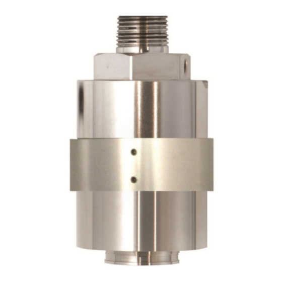
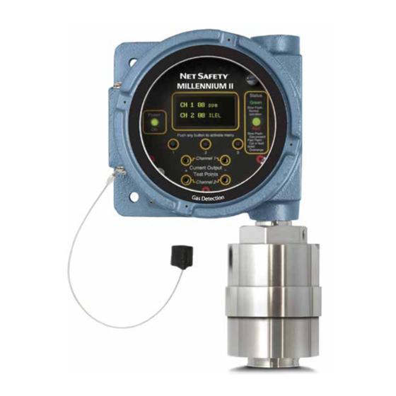
Millennium II SC310 Combustible Gas Sensor
Related Manuals for Emerson Net Safety Millennium II SC310
Summary of Contents for Emerson Net Safety Millennium II SC310
-
Page 1
Safety Manual 00809-0100-4310, Rev AA May 2021 Millennium II SC310 Combustible Gas Sensor… -
Page 2
Emerson does not assume any liability arising out of the application or any use of any product or circuit described herein;… -
Page 3
SHALL INCLUDE, BUT NOT BE LIMITED TO, LOSS OF ANTICIPATED PROFITS, REVENUE OR USE AND COSTS INCURRED INCLUDING WITHOUT LIMITATION FOR CAPITAL, FUEL AND POWER, AND CLAIMS OF BUYER’S CUSTOMERS. Contact information Emerson Toll Free + 866 347 3427 6021 Innovation Blvd. -
Page 5
This manual has been designed to ensure the sensor is set-up, operated and maintained properly. It outlines specific details of the Catalytic Bead sensor and addresses calibration procedures using the Millennium II Basic Transmitter and the Millennium II Transmitter. If you encounter any problems, see Troubleshooting or contact Emerson representative. Net Safety SC310… -
Page 6
Figure 1-1: Dimensional drawing for Sensor with Millennium II Series Transmitters Table 1-1: Millennium II Enclosure and Sensor Dimensions (A through H) in Inches (in) and Millimeters (mm) Millennium transmitter enclosure Transmitter and sensor (AL) Transmitter and sensor (SS) Emerson.com/Rosemount… -
Page 7
Safety Manual Introduction 00809-0100-4310 May 2021 Table 1-2: Millennium II Basic Enclosure (or Junction Box Enclosure) and Sensor Dimensions (A through J) in Inches (in) and Millimeters (mm) Millennium II basic and sensor Transmitter and sensor(AL) Transmitter and sensor(SS) Millennium II basic and sensor Transmitter and sensor (AL) -
Page 8
Introduction Safety Manual May 2021 00809-0100-4310 Emerson.com/Rosemount… -
Page 9: Locate Sensor
Safety Manual Plan 00809-0100-4310 May 2021 Plan Locate sensor Prior to the installation process, develop a plan. Although there are no absolute rules determining the quantity of detectors or location of a sensor, consider the following points when planning the installation. •…
-
Page 10
Calibration gas can then be applied from ground level. Emerson.com/Rosemount… -
Page 11
Safety Manual Plan 00809-0100-4310 May 2021 To compensate for the effect of distance when remotely calibrating, in separation configuration, decrease the tubing diameter or increase the calibration gas flow rate between the gas canister and sensor. On initial install, always confirm tubing run is not affecting calibration. -
Page 12
Plan Safety Manual May 2021 00809-0100-4310 Emerson.com/Rosemount… -
Page 13: Unpack And Inspect
Carefully remove all the components from the packaging and check them against the enclosed packing list. Inspect all components for any obvious damage such as broken or loose parts. If you find any components missing or damaged, notify your local Emerson representative or the factory immediately. Mount Ensure the transmitter and sensor are securely mounted as per local regulations.
-
Page 14
Sensors may also be mounted remotely from transmitters using certified junction boxes with designated terminals. Transmitter and junction box enclosures are shipped with one stopping plug fitted and tightened to a ¾-in. NPT conduit entry. Emerson.com/Rosemount… -
Page 15: Installation Checklist
Safety Manual Installation 00809-0100-4310 May 2021 3.3.2 Wire sensor WARNING Do not open enclosures in a classified area (Do not open when an explosive atmosphere may be present). Ensure the power to the transmitter is switched off before connecting sensor wires. Avoid touching electronic components, as they are susceptible to electrostatic discharge (ESD).
-
Page 16
Installation Safety Manual May 2021 00809-0100-4310 Emerson.com/Rosemount… -
Page 17: Operation
Safety Manual Operation 00809-0100-4310 May 2021 Operation Configuration settings All configuration settings are accessed through the Millennium II series transmitters. This is done by setting DIP switches on the Millennium II Basic Transmitter and by selecting menu options in the Millennium II Transmitter. Some configurations are done by the ®…
-
Page 18
May 2021 00809-0100-4310 disruption of its calibration. As an extra safety precaution, the system should be checked for accuracy after such over-range exposure and if necessary re-calibrated. The system will need to be reset to clear the latched output. Emerson.com/Rosemount… -
Page 19: Modbus Registers
Safety Manual Output 00809-0100-4310 May 2021 Output Alarm and fault outputs Sensor alarm and fault outputs are generated by the Millennium II series transmitters based on communication with sensors, however some output values, registers, etc, may vary depending on sensor type. The default alarm levels (point) for the sensor are: 20 percent for the low level and 40 percent for the high level.
-
Page 20
Output Safety Manual May 2021 00809-0100-4310 Emerson.com/Rosemount… -
Page 21: Calibration Procedure
Safety Manual Maintaining 00809-0100-4310 May 2021 Maintaining Calibration procedure There are specific steps to be followed when calibrating with the Millennium II Basic and the Millennium II Transmitters. These steps should be followed if accurate results are to be obtained. The calibration of Catalytic Bead sensors requires the presence of oxygen. An air balanced calibration gas should be used for calibration, otherwise these sensors will not calibrate properly.
-
Page 22
Millennium II Basic Transmitter manual calibration procedure below and/or Figure 6-1 before attempting calibration. Millennium II Basic Transmitter Normal Calibration Procedure Calibrations may be performed either by using the magnet (non – intrusive) or by using the push button (intrusive). Emerson.com/Rosemount… -
Page 23
Safety Manual Maintaining 00809-0100-4310 May 2021 Procedure 1. Confirm successful power up of Transmitter, (green blip/blink of status LED every second: no fault indicated). 2. Bypass any output alarms (recommended). 3. For analog model connect a standard current meter to the transmitter’s Test Jacks (not required but gives visual confirmation). -
Page 24
6-1: Calibration Flow chart for Millennium II Basic Transmitter on next page for additional reference. Figure 6-1: Calibration Flow Chart for Millennium II Basic Transmitter Note See the Millennium II Basic transmitter manual when locating calibration switch (push button) or magnetic switch. Emerson.com/Rosemount… -
Page 25
Safety Manual Maintaining 00809-0100-4310 May 2021 6.1.2 Calibrating with the Millennium II Transmitter The following procedures are specific to this controller and should be followed to ensure accurate calibration and detection of gases. The transmitter also offers some flexibility in the use of calibration gas. -
Page 26
7. Apply clean air when “Apply Clean Air” is displayed, then select “Z & Span” using (Menu button 1 or Reed Switch 1) for normal calibration. “Setting zero” will be displayed as the sensor is being zeroed. (Ensure no contaminant gases are present if ambient air is being used). Emerson.com/Rosemount… -
Page 27
Safety Manual Maintaining 00809-0100-4310 May 2021 8. Apply 50% calibration gas (or % Cal. gas value chosen in menu option) when prompted. Recommendation: Flow span gas at a rate of 0.5 liter per minute to the sensor for direct calibrations. If sensor is remotely mounted and long tubing run is used, increase gas flow rate (e.g. -
Page 28: Cross Sensitivity
Safety Manual May 2021 00809-0100-4310 Figure 6-2: Calibration Flow Chart for Millennium II Transmitter 6.1.3 Cross sensitivity The SC310 sensor will react to airborne materials that burn or explode in oxygen atmospheres, such as gaseous hydrocarbons. Certain compounds, including Halogen- Emerson.com/Rosemount…
-
Page 29: Replace Sensor
Safety Manual Maintaining 00809-0100-4310 May 2021 containing hydrocarbons, can reduce sensor response. In some instances this reduction in response is reversible and the sensor will operate normally when such a compound or gas is removed. Exposure to organic phosphates, esters and Silicon-containing compounds will «poison»…
-
Page 30: Troubleshooting
See for certified temperatures. Accessories Table 6-3: Available Spare Parts Description Part number Calibration cup/splash guard CCS-1 JB-MPD-A (aluminum) or JB-MPD-S (316 Separation kit stainless steel) Dust filter assembly DSC-1 Replacement cat bead sensor SC310-100 IP66/67 hydrophobic filter IPF-001 Emerson.com/Rosemount…
-
Page 31: How To Return Equipment
Safety Manual Maintaining 00809-0100-4310 May 2021 How to return equipment A Material Return Authorization number is required in order to return equipment. Please contact Rosemount at (866) 347-3427, before returning equipment or consult our Service Department to possibly avoid returning equipment. If you are required to return equipment, include the following information: •…
-
Page 32
Maintaining Safety Manual May 2021 00809-0100-4310 Emerson.com/Rosemount… -
Page 33: Electrostatic Sensitive Device (Esd)
Safety Manual Electrostatic sensitive device (ESD) 00809-0100-4310 May 2021 Electrostatic sensitive device (ESD) Definition: Electrostatic discharge (ESD) is the transfer, between bodies, of an electrostatic charge caused by direct contact or induced by an electrostatic field. The most common cause of ESD is physical contact. Touching an object can cause a discharge of electrostatic energy—ESD! If the charge is sufficient and occurs near electronic components, it can damage or destroy those components.
-
Page 34
Electrostatic sensitive device (ESD) Safety Manual May 2021 00809-0100-4310 Emerson.com/Rosemount… -
Page 35: Resistance Table
Safety Manual Resistance table 00809-0100-4310 May 2021 Resistance table AWG #20 AWG #18 AWG #16 AWG #14 Distance (Feet) 0.5 mm 0.8 mm 1.0 mm 2.0 mm 1.02 0.64 0.40 0.25 2.03 1.28 0.80 0.51 3.05 1.92 1.20 0.76 4.06 2.55 1.61 1.01…
-
Page 36
Resistance table Safety Manual May 2021 00809-0100-4310 Emerson.com/Rosemount… -
Page 37
Safety Manual Millennium II Catalytic Bead Sensor specifications 00809-0100-4310 May 2021 Millennium II Catalytic Bead Sensor specifications Sensor Specification Performance Power consumption (10.5 – 32 Vdc) < 1.5 W Voltage range 10.5 – 32 Vdc EN50270: 2006 (pending) FM63101/6320 (Radio Frequency Interference) T50 <… -
Page 38
1. Consult the manufacturer if dimensional information on the flameproof joints is necessary 2. The flying leads of the sensors shall be suitably protected against mechanical damage and terminated within a terminal or junction facility suitable for the conditions of use. Emerson.com/Rosemount… -
Page 39
Safety Manual 00809-0100-4310 May 2021 Net Safety SC310… -
Page 40
2021 Emerson. All rights reserved. The Emerson logo is a trademark and service mark of Emerson Electric Co. Net Safety is a mark of one of the Emerson family of companies. All other marks are the property of their respective…
На этой странице вы можете совершенно бесплатно скачать Инструкция по эксплуатации Emerson Millennium II Multi-Channel Transmitter M21.
У документа PDF Инструкция по эксплуатации 47 страниц, а его размер составляет 2.19 Mb.
Читать онлайн Пожарные газовые извещатели Emerson Millennium II Multi-Channel Transmitter M21 Инструкция по эксплуатации

Скачать файл PDF «Emerson Millennium II Multi-Channel Transmitter M21 Инструкция по эксплуатации» (2.19 Mb)
Популярность:
1010 просмотры
Подсчет страниц:
47 страницы
Тип файла:
Размер файла:
2.19 Mb
Прочие инструкции Emerson Пожарные газовые извещатели


Прочие инструкции Emerson


-
Contents
-
Table of Contents
-
Troubleshooting
-
Bookmarks
Quick Links
Reference Manual
Part Number: MAN-0076, rev. 09
Release: June 2016
Millennium II Multi-Channel Transmitter
Related Manuals for Emerson Net Safety Millennium II
Summary of Contents for Emerson Net Safety Millennium II
-
Page 1
Reference Manual Part Number: MAN-0076, rev. 09 Release: June 2016 Millennium II Multi-Channel Transmitter… -
Page 3
Important Instructions Net Safety Monitoring, Inc (Net Safety) designs, manufactures and tests products to function within specific conditions. Because these products are sophisticated technical instruments, it is important that the owner and operation personnel must strictly adhere both to the information printed on the product nameplate and to all instructions provided in this manual prior to installation, operation, and maintenance. -
Page 4
Net Safety and the Net Safety logo are registered trademarks of Net Safety Monitoring, Inc. The Emerson logo is a trademark and service mark of the Emerson Electric Company. Copyright © 2016 by Rosemount, Shakopee, MN. -
Page 5
Warranty 1. Limited Warranty. Subject to the limitations contained in Section 10 (Limitation of Remedy and Liability) herein, Seller warrants that (a) the licensed firmware embodied in the Goods will execute the programming instructions provided by Seller; (b) that the Goods manufactured by Seller will be free from defects in materials or workmanship under normal use and care;… -
Page 7: Table Of Contents
Reference Manual Table of Contents MAN-0076 Revision 09 June 2016 Contents Section 1 : Introduction …………..1 Models covered ………………….1 Service support ………………….1 Return of material………………….1 Product recycling/disposal ……………….. 1 Section 2 : Installation …………..2 Unpacking and inspection ……………….. 2 Dimensions ……………………
-
Page 8
Table of Contents Reference Manual June 2016 MAN-0076, Revision 09 4.14 Manual reset ………………….. 22 4.15 Self-test relay………………….22 4.16 Sensor upper limit (range) ………………23 4.17 Select gas type ………………….23 4.18 Calibration gas value………………..24 4.19 Serial number and firmware version …………….24 4.20 Exit …………………….. -
Page 9
Reference Manual Table of Contents MAN-0076 Revision 09 June 2016 11.3 FC Models ……………………43 11.3.1 North American ……………….. 43 11.3.2 IECEx (aluminum) ………………43 11.3.3 IECEx (stainless) ……………….. 43 Section 12 : Ordering information ……….44 12.1 M21 single channel transmitter ……………… 44 12.2 M22 dual channel transmitter ……………… -
Page 11: Section 1: Introduction
Modbus RTU digital. Service support Technical support for this product can be provided by contacting your local Emerson Process Management representative or by contacting the Technical Support department at +1 866 347 3427 (toll free) or Safety.CSC@Emerson.com.
-
Page 12: Section 2: Installation
Installation Reference Manual June 2016 MAN-0076, Revision 09 Section 2: Installation Unpacking and inspection Carefully remove all of the components from the packaging and verify them against the enclosed packing list. Inspect all components for any obvious damage such as broken or loose parts. If you find any components missing or damaged, notify your local Net Safety representative or the factory immediately.
-
Page 13: Faceplate Rotation
Reference Manual Installation MAN-0076, Revision 09 June 2016 Ensure the orientation allows proper wiring and adequate wire length inside the transmitter enclosure. When determining suitable enclosure orientation for specific applications, installers should observe all local regulations and guidelines for mounting enclosures. Figure 2-2 Different enclosure orientations 2.3.2 Faceplate rotation…
-
Page 14: Wiring
Installation Reference Manual June 2016 MAN-0076, Revision 09 Insert metal standoffs in the appropriate mounting holes Tighten metal standoffs with ¼” hex tool to secure electronics module Reconnect wiring Replace faceplate, then fit and hand tighten locking knobs to metal standoffs by turning clockwise Replace enclosure cover.
-
Page 15: Terminal Connection
Reference Manual Installation MAN-0076, Revision 09 June 2016 Wiring codes and regulations may vary. Wiring must comply with all applicable regulations relating to the installation of electrical equipment in a hazardous area and is the responsibility of the installer. If in doubt, consult a qualified official before wiring the system.
-
Page 16: Internal Ground Screw
Installation Reference Manual June 2016 MAN-0076, Revision 09 · Detection instruments · Customer connected equipment · Wiring Net Safety designs and manufactures its detection equipment under rigid quality control management systems and makes every effort to design for the harshest of industrial environments. The other components of the system –…
-
Page 17
Reference Manual Installation MAN-0076, Revision 09 June 2016 · The jacket and shielding of the cable should be stripped back to permit the seal to form around the individual wires. This will prevent air particles and water leakage through the inside of the shield and into the enclosure ·… -
Page 18: Remotely Mounted Sensors Jumper Configuration
Installation Reference Manual June 2016 MAN-0076, Revision 09 Always ensure that JP3 and JP4 jumpers are in the correct position depending on the current output configuration chosen 2.4.9 Remotely mounted sensors jumper configuration Sensor separation from the transmitter may extend up to 2000 feet (600 meters) in which case a junction box is required.
-
Page 19: Remote Reset
Reference Manual Installation MAN-0076, Revision 09 June 2016 Sensor Terminals Transmitter power terminals Sensor wires Transmitter sensor board terminal Transmitter terminal Function designation designation White +Vdc (from transmitter) Remote Reset SigA +Vdc (10.5-32Vdc) Power (+) Blue SigB Power (-) Black 4-20 (CH1) Channel #1 current loop output Green…
-
Page 20: Sensor Separation/Remote Mounting Of Sensor
Installation Reference Manual June 2016 MAN-0076, Revision 09 Figure 2-8 Remote reset wiring Sensor separation/remote mounting of sensor When it is necessary to mount the sensor remotely (separated from transmitter), by way of junction box and conduit, it is important that the installer follow the necessary requirements and guidelines relating to sensor separation and cable selection.
-
Page 21: Wiring Diagrams
Reference Manual Installation MAN-0076, Revision 09 June 2016 2.5.1 Wiring diagrams Wiring drawings show general ways in wiring the system for analog signal output. Consult qualified personnel on specific wiring requirements. Figure 2-10 Non-isolated terminal connection Installation…
-
Page 22: Installation Checklist
Installation Reference Manual June 2016 MAN-0076, Revision 09 Figure 2-11 Isolated terminal connection Installation checklist Review the following checklist prior to turning the power on to the transmitter after installation has been completed: □ Ensure that the transmitter and sensor are properly and firmly mounted. □…
-
Page 23: Section 3: Operation
Reference Manual Operation MAN-0076, Revision 09 June 2016 Section 3: Operation Transmitter and faceplate description Figure 3-1 Faceplate description 3.1.1 Display The Millennium II is equipped with an Organic LED (OLED) display. It allows the user to see the concentration of gas present for each individual channel and the various options offered. The display has a wide temperature rating and will operate well in lowly lit conditions.
-
Page 24: Current Loop Measurement (Test Jacks)
Operation Reference Manual June 2016 MAN-0076, Revision 09 3.1.3 Current loop measurement (test jacks) Do not open the transmitter, sensor, or junction box enclosure when in a classified area or when an explosive atmosphere may be present unless the power to the transmitter has been removed. For convenience, a pair of test jacks for each analog output is provided on the front face of the display module.
-
Page 25: Section 4: Programming
Reference Manual Programming MAN-0076, Revision 09 June 2016 Section 4: Programming Menu options The main menu provides access to various functional settings/options, as seen in the list below. Each menu option has a submenu, where configuration is completed. Calibrate Sensor Enable/Disable Channels Set Alarm Level Set Relay Option (available on relay models)
-
Page 26
Programming Reference Manual June 2016 MAN-0076, Revision 09 Figure 4-1 Programming flowchart Enter Main Menu? Calibrate Sensor? Select Display Selftest Relay? Language? Enable/Disable Modbus Setup Sensor Upper Limit Channels? (Range) Set Alarm Level? Setup Current Date? Select Gas Type Set Relay Option? Setup Current Time? Cal Gas Value Relay Assignment? -
Page 27: Calibrate Sensor
Reference Manual Programming MAN-0076, Revision 09 June 2016 Calibrate sensor This menu function allows the user to perform a calibration on the connected sensor. Refer to Section for the calibration procedure. Enable/Disable channels This option allows the Millennium II Transmitter channels to be enabled or disabled. The default value is channel 1 (CH1) enabled for single sensor models (model M21) while channel 2 (CH2) is permanently disabled.
-
Page 28: Set Relay Option
Programming Reference Manual June 2016 MAN-0076, Revision 09 Use switch 1 to increase the existing values representing previously set alarm levels/points and switch 2 to highlight and scroll across values. After setting desired alarm points, select “Exit” at each menu stage (sub menu and main menu). Apply test gas to confirm alarm level settings.
-
Page 29
Reference Manual Programming MAN-0076, Revision 09 June 2016 Prior to assigning relays, configure the alarm levels (points). See Section ‘4.2.4 Viewing and setting alarm levels (points)’, and then follow the steps and example below to configure the Alarm relays. Also see Table 3, Example and Table 4. -
Page 30: Alarm Mode Setting
Programming Reference Manual June 2016 MAN-0076, Revision 09 Alarm mode setting Only used on Oxygen (ST341) sensors This option is available for detecting oxygen levels. The user is allowed to set up two Alarm points/level (normal oxygen level is 20.9 %) under three available Alarm Modes. These Alarm Modes are: Above- Above, Below-Below and Below-Above.
-
Page 31: Setup Current Date
Reference Manual Programming MAN-0076, Revision 09 June 2016 Activate the enter key (switch 3) when the desired value is displayed. After setting the baud rate, exit this sub menu option using switch 3, and then activate the down arrow key (switch 2) to highlight ‘Parity Bit’. Activate switch 3, then activate the up key (switch 2), or the down key (switch 1) to choose a value.
-
Page 32: Manual Reset
Programming Reference Manual June 2016 MAN-0076, Revision 09 Activate the enter key (switch 3) to display the sub menu. The most recent event will be displayed. Select the up arrow key (switch 1) and the down arrow key (switch 2) to toggle through all past events.
-
Page 33: Sensor Upper Limit (Range)
Reference Manual Programming MAN-0076, Revision 09 June 2016 unwanted alarm activation. Enable external equipment once testing is completed. The Self-test relay option continuously turns relays on and off to ensure that they are functioning properly. The Fault Relay is tested first, automatically followed by tests on Relay 1, 2, and 3. After the relays have been tested, “Relay Test Complete”…
-
Page 34: Calibration Gas Value
Programming Reference Manual June 2016 MAN-0076, Revision 09 4.18 Calibration gas value This option allows the user to select the calibration gas value in the transmitter main menu. Although it is recommended that 50% span gas should be used for calibration, for some sensors, the transmitter will allow tolerance/flexibility in the calibration gas available;…
-
Page 35: Section 5: Calibration Procedure
Reference Manual Calibration procedure MAN-0076, Revision 09 June 2016 Section 5: Calibration procedure Full calibration procedure Prior to attempting calibration read and understand the calibration procedure below. Also see Figure for additional reference. The following calibration procedure should be followed to ensure an accurate correlation between the output signal and the gas concentration.
-
Page 36
Calibration procedure Reference Manual June 2016 MAN-0076, Revision 09 The “Zero” calibration option is selected if the sensor is only being zeroed (this not a complete calibration) It does not require the application of span gas, as only the sensor’s zero point is adjusted. Ensure that no contaminants are present, if the surrounding air is to be used for Zeroing. -
Page 37
Reference Manual Calibration procedure MAN-0076, Revision 09 June 2016 Figure 5-1 Calibration flowchart Enter Main Menu? Note: Calibration process is identical for Channel #2 Calibrate Sensor? Remove air canister (if used) — Zero calibration complete, full calibration continue to next block CH 1: Apply 50% span gas Calibrate Sensor #1 Note: Some sensor types can… -
Page 38: Status Conditions During Calibration
Calibration procedure Reference Manual June 2016 MAN-0076, Revision 09 Status conditions during calibration Condition Current output LED indication Relay outputs Green Fault Alarm Sensor is zeroing itself 3 mA Solid Normal state Normal state Sensor is waiting until it detects application 3.3 mA Very fast Normal state…
-
Page 39: Section 6: Monitoring And Outputs
Reference Manual Monitoring and outputs MAN-0076, Revision 09 June 2016 Section 6: Monitoring and outputs Analog 4-20mA A 4-20 mA current output is used to transmit the transmitter and sensor status and fault codes to other devices. This output can be wired for isolated or non-isolated operation. A 4.0 mA output indicates normal operation;…
-
Page 40: Relays (Optional)
Monitoring and outputs Reference Manual June 2016 MAN-0076, Revision 09 Figure 6-1 Analog/HART wiring Relays (Optional) Optional electromechanical relays have Form-C SPDT contacts rated 5 Amps at 30 VDC/ 250 VAC. There are four physical relays; one Fault and three Alarm relays. These relays have Normally Open and Normally Closed contacts at the output terminals.
-
Page 41: Rs-485 Modbus Rtu (Optional)
Reference Manual Monitoring and outputs MAN-0076, Revision 09 June 2016 The fault relay is normally energized when no fault conditions are present and is set up for non-latching. The operation of the fault relay is not configurable. The Millennium II transmitter provides various fault conditions to indicate that the transmitter or connected sensor(s) are not operating as expected.
-
Page 42: Modbus Registers
Monitoring and outputs Reference Manual June 2016 MAN-0076, Revision 09 6.4.1 Modbus registers Reg# Meaning Readable Writeable 40001 Concentration value as calculated by sensor (RTUsensor_out), Channel 1 40002 Sensor status (RTUsensor_stat), Channel 1 40003 Temperature of sensor element housing in Kelvin (RTU temperature), Channel 1 40004 RFU, Channel 1, always read as 0x0000 40005…
-
Page 43: Transmitter Output Operation
Reference Manual Monitoring and outputs MAN-0076, Revision 09 June 2016 Transmitter output operation The following table outlines the operation of the outputs of the Millennium II transmitter under different conditions. These outputs include the analog output, LED indications, and the relay outputs. For the outputs’…
-
Page 44: Fault Conditions
Monitoring and outputs Reference Manual June 2016 MAN-0076, Revision 09 The fault detection circuitry does not monitor the operation of external response equipment or external wiring to the transmitter. It is important that external equipment and wiring be checked periodically to ensure they are operational. Fault conditions Fault conditions will override any alarm conditions because the sensor may be unable to detect a gas exposure reliably, as such, the alarm relay will not provide an output.
-
Page 45: Sensor Fault Conditions
Reference Manual Monitoring and outputs MAN-0076, Revision 09 June 2016 6.7.2 Sensor fault conditions Fault conditions that the various Millennium II sensors detect are as follows: Fault condition SC310 SC311 ST322 ST332 ST340 ST320 ST330 ST341 ST360 Zero calibration failure Span calibration failure Low temperature High temperature…
-
Page 46: Section 7: Maintenance
Maintenance Reference Manual June 2016 MAN-0076, Revision 09 Section 7: Maintenance Periodic response check Net Safety Monitoring recommends that a bump test be performed every 90 days to ensure continued functionality and accuracy of the detection system. Full calibration is recommended when the sensor fails to meet acceptable accuracy standards.
-
Page 47: Spare Parts And Accessories
Reference Manual Maintenance MAN-0076, Revision 09 June 2016 Spare parts and accessories Description Part Number 3/4 NPT ATEX certified plug — Aluminum CP-AL-002 3/4 NPT ATEX certified plug — Stainless Steel CP-SS-001 Aluminum separation kit JB-MPD-A Stainless Steel separation kit JB-MPD-S Magnet assembly MAGNET-1…
-
Page 48
Maintenance Reference Manual June 2016 MAN-0076, Revision 09 Description Part Number 3″ Pipe Mounting kit — All Millennium II & ECO-SENSE Gas Detectors UN-MK-33 (stainless steel) Maintenance… -
Page 49: Section 8: Electrostatic Sensitive Device
Reference Manual Electrostatic sensitive device MAN-0076, Revision 09 June 2016 Section 8: Electrostatic sensitive device Definition: Electrostatic discharge (ESD) is the transfer, between bodies, of an electrostatic charge caused by direct contact or induced by an electrostatic field. The most common cause of ESD is physical contact. Touching an object can cause a discharge of electrostatic energy.
-
Page 50: Section 9: Wire Resistance Table
Wire resistance table Reference Manual June 2016 MAN-0076, Revision 09 Section 9: Wire resistance table Distance AWG #20 AWG #18 AWG #16 AWG #14 Feet (Meters) 0.5 mm 0.8 mm 1.0 mm 2.0 mm 100 (30.5) 1.02 0.64 0.40 0.25 200 (61) 2.03 1.28…
-
Page 51: Section 10: Specifications
Reference Manual Specifications MAN-0076, Revision 09 June 2016 Section 10: Specifications 10.1 Electrical 10.1.1 Operating voltage range 10.5 to 32 VDC 18 to 32 VDC (HART versions only) 10.1.2 Power consumption 2.4 W @ 24 VDC (average — varies by sensor types/quantities) 10.1.3 EMC compliance EN 50270:2006 per EMC directive 2004/108/EC…
-
Page 52: Weight
Specifications Reference Manual June 2016 MAN-0076, Revision 09 10.3.3 Weight Aluminum: 5.5 lbs (2.5 kg) Stainless Steel: 7.0 lbs (3.2 kg) 10.4 Warranty 3 years Specifications…
-
Page 53: Section 11: Certifications
Reference Manual Certifications MAN-0076, Revision 09 June 2016 Section 11: Certifications 11.1 North American Class I, Division 1, Groups BCD T5 Class I, Zone 1, AEX/Ex d IIB+H -50 °C ≤ Ta ≤ + 85 °C NEMA Type 4X/IP67 FM6320, ANSI/ISA 12.13.01, CSA 22.2 No. 152:2006 11.2 IECEx Ex d IIB+H…
-
Page 54: Section 12: Ordering Information
Ordering information Reference Manual June 2016 MAN-0076, Revision 09 Section 12: Ordering information 12.1 M21 single channel transmitter Model Description Millennium II Single Channel Transmitter Output Description Analog Output Analog and Digital RS485 Modbus RTU Protocol Outputs Analog and HART Protocol Outputs Analog, HART Protocol and Relay Outputs Analog and Relay Outputs Analog, Relay and Digital RS485 Modbus RTU Protocol Outputs…
-
Page 55: M22 Dual Channel Transmitter
Reference Manual Ordering information MAN-0076, Revision 09 June 2016 12.2 M22 dual channel transmitter Model Description Millennium II Dual Channel Transmitter Output Description Analog Output Analog and Digital RS485 Modbus RTU Protocol Outputs Analog and Relay Outputs Analog, Relay and Digital RS485 Modbus RTU Protocol Outputs Enclosure Description Aluminum…
-
Page 56
©2016 Emerson Process Management. All rights reserved. The Emerson logo is a trademark and service mark of Emerson Electric Co. Rosemount is a mark of one of the Emerson Process Management family of companies. All other marks are property of their respective owners.
Краткое содержание страницы № 1
MILLENNIUM II
Multi-Channel Transmitter
User Manual
Single or Dual Channel
P Pa ar rt Nu t Nu mber mbe: MAN r: MAN -00 -00 7676 Re Rev Apr v 05 l
December 07, 2012
2008
Краткое содержание страницы № 2
IMPORTANT INFORMATION This manual is for informational purposes only. Although every effort has been made to ensure the correctness of the information, technical inaccuracies may occur and periodic changes may be made without notice. Net Safety Monitoring Inc., assumes no responsibility for any errors contained within this manual. If the products or procedures are used for purposes other than as described in the manual, without receiving prior confirmation of validity or suitabilit
Краткое содержание страницы № 3
TABLE OF CONTENTS IMPORTANT INFORMATION …………………………………………………………………………………………………………………………………… 2 WARRANTY ……………………………………………………………………………………………………………………………………………………………….. 2 CONTACT INFORMATION …………………………………………………………………………..
Краткое содержание страницы № 4
4.2.8 Select Display Language ………………………………………………………………………………………………………………………………. 30 4.2.9 MODBUS Setup …………………………………………………………………………………………………………………………………………… 30 4.3.0 Setup Current Date ………………………………………………………………………………………………..
Краткое содержание страницы № 5
INTRODUCTION Building on the outstanding legacy of the Millennium Series, Net Safety’s latest innovation in this line of continuously evolving industrial transmitters and sensors, the Millennium II, pushes the boundaries of what you can expect from your detection system. Combined with state of the art “Smart” sensors, users will receive a detection system which is both versatile and reliable for fast, accurate and continuous monitoring of gases in extreme environments. THE PRODUCT TR
Краткое содержание страницы № 6
Enclosure Dimensions The Millennium II Transmitter enclosure is available in Aluminum (AL6061) and Stainless Steel (SS316). Dimensions are in inches and millimeters. Figure 1: Transmitter Enclosure Dimensional Drawing * M20, ½” NPT, & ½” BSP threads also available 6 MAN-0076 Rev 05 Millennium II December 07, 2012 Net Safety Monitoring Inc
Краткое содержание страницы № 7
SECTION 1: Installation 1.1 Unpack Carefully remove all components from the packaging and check them against the enclosed packing list. Inspect all components for obvious damage such as broken or loose parts. If you find any components missing or damaged, notify the representative or Net Safety Monitoring, immediately. 1.2 Mounting Ensure transmitter and sensor are securely mounted, taking into consideration all requirements. Sensors may be installed directly to transmitters or
Краткое содержание страницы № 8
1.2.2 Transmitter electronics module and Relay options The transmitter electronics module may be equipped with 4 electromechanical relays or 4 solid-state relays which are mounted to the main terminal board via plastic standoffs. Relay boards are field replaceable by simply unlocking the plastic standoffs with a small flat head screw driver. Remove relay board after unlocking standoffs, insert the replacement relay board, and then lock the plastic standoff with the screw driver. See F
Краткое содержание страницы № 9
1.2.3 Rotating electronics module relative to enclosure and conduit entries The electronics module consists of the relay board and faceplate (Display/CPU assembly) with main terminal board. To rotate the electronics module, follow these instructions: 1. Turn off power to transmitter and ensure area is de-classified. 2. Remove the enclosure cover. 3. Unscrew both the locking knobs and free from two metal standoffs. 4. Lift transmitter faceplate from enclosure. 5. Disconnect existi
Краткое содержание страницы № 10
SECTION 2: Wiring and installation 2.1 Field Installation Warning Wiring codes and regulations may vary. ATEX requires that supply connection wiring must be rated at least 5°C above the maximum ambient temperature of 85°C. Wiring must comply with all applicable regulations relating to the installation of electrical equipment in a hazardous area and is the responsibility of the installer. If in doubt, consult qualified personnel before wiring the system. Warning Do not open the tr
Краткое содержание страницы № 11
It is the responsibility of the installer to install conduit seals where necessary, and to design conduit runs to ensure that condensation does not accumulate and collect inside the enclosure. 2.1.2 Cable choice and guidelines Radio Frequency Interference (RFI) can be caused by nearby electrical devices (transformers, high voltage equipment) as well as handheld communications devices/radios, which when activated, may impede the proper functioning of the transmitter and sensor. Selecti
Краткое содержание страницы № 12
Armored Cable preparation procedure: 1. Prepare the armored instrument cable as illustrated in Figure 5 and follow all assembly and/or preparation instructions provided by the cable and/or cable gland manufacturer. 2. Install cable gland and reducer onto the cable. 3. Ensure four (4) inches of wire length is available for connecting to terminals inside the junction box. 4. Use a small flat head screw driver when connecting wires to connector terminals. See Figure 6. 5. Connect sensor w
Краткое содержание страницы № 13
Warning Before wiring, ensure that power to transmitter is switched off. When connecting cable wires, use a small screwdriver to gently press down and hold the spring connector open. Insert the appropriate wire into the open connector hole, releasing the screwdriver to secure the wire. See Figure 6. Figure 6: Connecting wires Warning Avoid touching electronic components, as they are susceptible to electrostatic discharge (ESD). Refer to Appendix A, “Electrostatic Sensitive De
Краткое содержание страницы № 14
2.1.4 Remotely mounted sensors jumper configuration Sensor separation from the transmitter may extend up to 2000 feet in which case a junction box is required. When mounting sensor remotely (separating sensor from transmitter), Jumpers JP1 and JP2 should be installed over the pins. Jumpers and pins are located on the main terminal board near the sensor terminals. JP1 is for channel 1 and JP2 is for channel 2. Refer to Figure 8. Figure 8: Separation Jumpers positions
Краткое содержание страницы № 15
2.1.5 Sensor and Transmitter terminals Warning Before wiring, ensure power to the unit is switched off. Connect the sensor wires to the sensor terminals of the transmitter and connect the transmitter’s power and output terminals to the wiring leading to the Power source/panel. Refer to the configuration tables below for sensor as well as transmitter power and output terminal designations. Table 1: Sensor and Transmitter Terminals Sensor Terminals Transmitter Power Terminals Senso
Краткое содержание страницы № 16
2.1.6 Remote Reset If the alarm relays are configured for latching operation it may be desirable to reset latched alarms from a remote location. In this case a normally open, momentary push-button switch may be connected across terminals RST and COM. Figure 10: Remote Reset wiring 2.1.7 Sensor Separation/ Remote mounting of sensor When necessary to mount sensor
Краткое содержание страницы № 17
2.1.8 Wiring drawings Wiring drawings show general ways in wiring the system for analog signal output. Consult qualified personnel on specific wiring requirements. Figure 12: Non-isolated terminal connection 17 MAN-0076 Rev 05 Millennium II December 07, 2012 Net Safety Monitoring Inc
Краткое содержание страницы № 18
Figure 13: Isolated terminal connection 18 MAN-0076 Rev 05 Millennium II December 07, 2012 Net Safety Monitoring Inc
Краткое содержание страницы № 19
2.1.9 Installation Checklist Prior to operation, it is important to do the following checks. Ensure transmitter and sensor are properly and firmly mounted. Ensure that the enclosure certified stopping plug is tightened to unused conduit entry/opening, to maintain ingress protection and flameproof type protection. Ensure transmitter and sensor are not being obstructed; transmitter and sensor are accessible and target gas is not inhibited from reaching sensor. Remove sens
Краткое содержание страницы № 20
SECTION 3: Transmitter and faceplate description 3.1 Transmitter Power Up After power is applied to the transmitter, a warm-up routine will begin, the duration of which depends on the sensor type. The display will indicate the sensor warming up and the Status LED will flash Slow Red and current output will be 3.0mA. After the warm-up period, the transmitter will enter normal operation and the screen will display: “Channel 1 00 %LEL (or PPM), Channel 2 00 %LEL (or PPM).” For dual
На этой странице вы можете совершенно бесплатно скачать Инструкция по эксплуатации Emerson Millennium II Multi-Channel Transmitter M21.
У документа PDF Инструкция по эксплуатации 47 страниц, а его размер составляет 2.19 Mb.
Читать онлайн Пожарные газовые извещатели Emerson Millennium II Multi-Channel Transmitter M21 Инструкция по эксплуатации
Скачать файл PDF «Emerson Millennium II Multi-Channel Transmitter M21 Инструкция по эксплуатации» (2.19 Mb)
Популярность:
999 просмотры
Подсчет страниц:
47 страницы
Тип файла:
Размер файла:
2.19 Mb
Прочие инструкции Emerson
Table of Contents for Emerson Net Safety Millennium II:
-
Reference Manual Installation MAN-0076, Revision 09 June 2016 Installation 5 Wiring codes and regulations may vary. Wiring must comply with all applicable regulations relating to the installation of electrical equipment in a hazardous area and is the responsibility of the installer. If in doubt, consult a qualified official before wiring the syst
-
Reference Manual Certifications MAN-0076, Revision 09 June 2016 Certifications 43 Section 11: Certifications 11.1 North American Class I, Division 1, Groups BCD T5 Class I, Zone 1, AEX/Ex d IIB+H 2 T5 -50 °C ≤ Ta ≤ + 85 °C NEMA Type 4X/IP67 FM6320, ANSI/ISA 12.13.01, CSA 22.2 No. 152:2006 11.2 IECEx Ex d IIB+H 2 T5 Gb IECEx DNV 12.0014 (Aluminum) IP66, controller only IECEx FMG 12.00
-
Reference Manual Installation MAN-0076, Revision 09 June 2016 Installation 3 Ensure the orientation allows proper wiring and adequate wire length inside the transmitter enclosure. When determining suitable enclosure orientation for specific applications, installers should observe all local regulations and guidelines for mounting enclosures. Figure 2-2 Different enclosure orientations 2.3.2 Faceplate rotation Before wiring or rotating electronics, ensure that
-
Reference Manual Ordering information MAN-0076, Revision 09 June 2016 Ordering information 45 12.2 M22 dual channel transmitter Model Description M22 Millennium II Dual Channel Transmitter Output Description A Analog Output AD Analog and Digital RS485 Modbus RTU Protocol Outputs AR Analog and Relay Outputs ARD Analog, Relay and Digital RS485 Modbus RTU Protocol Outputs Enclosure Descript
-
Warranty 1. Limited Warranty . Subject to the limitations contained in Section 10 (Limitation of Remedy and Liability) herein, Seller warrants that (a) the licensed firmware embodied in the Goods will execute the programming instructions provided by Seller; (b) that the Goods manufactured by Seller will be free from defects in materials or workmanship under normal use and care; and (c) Services will be performed by trained personnel using proper equipment and instrumentation for t
-
Reference Manual Installation MAN-0076, Revision 09 June 2016 Installation 7 · The jacket and shielding of the cable should be stripped back to permit the seal to form around the individual wires. This will prevent air particles and water leakage through the inside of the shield and into the enclosure · It is recommended that explosionproof drains and conduit breathers be used. In some applications, changes in temperature and barometric pressure can cause breathing which allows moist air
-
Monitoring and outputs Reference Manual June 2016 MAN-0076, Revision 09 32 Monitoring and outputs 6.4.1 Modbus registers Reg# Meaning Readable Writeable 40001 Concentration value as calculated by sensor (RTUsensor_out), Channel 1 X 40002 Sensor status (RTUsensor_stat), Channel 1 X 40003 Temperature of sensor element housing in Kelvin (RTU temperature), Channel 1 X 40004 RFU, Channel 1, always read as 0x0000 X 40005 RFU, Channel 1, always read
-
Maintenance Reference Manual June 2016 MAN-0076, Revision 09 36 Maintenance Section 7: Maintenance 7.1 Periodic response check Net Safety Monitoring recommends that a bump test be performed every 90 days to ensure continued functionality and accuracy of the detection system. Full calibration is recommended when the sensor fails to meet acceptable accuracy standards. This involves the application of calibration gas t
-
Reference Manual Programming MAN-0076, Revision 09 June 2016 Programming 21 9. Activate the enter key (switch 3) when the desired value is displayed. 10. After setting the baud rate, exit this sub menu option using switch 3, and then activate the down arrow key (switch 2) to highlight ‘Parity Bit’. 11. Activate switch 3, then activate the up key (switch 2), or the down key (switch 1) to choose a value. 12. Activate the exit key (switch 3) when the desired value i
-
Programming Reference Manual June 2016 MAN-0076, Revision 09 24 Programming 4.18 Calibration gas value This option allows the user to select the calibration gas value in the transmitter main menu. Although it is recommended that 50% span gas should be used for calibration, for some sensors, the transmitter will allow tolerance/flexibility in the calibration gas available; 10% to 60% span gas allowed
-
Installation Reference Manual June 2016 MAN-0076, Revision 09 12 Installation Figure 2-11 Isolated terminal connection 2.6 Installation checklist Review the following checklist prior to turning the power on to the transmitter after installation has been completed: □ Ensure that the transmitter and sensor are properly and firmly mounted. □ Ensure that stopping plugs are securely tightened on any unused conduit entri
-
Monitoring and outputs Reference Manual June 2016 MAN-0076, Revision 09 30 Monitoring and outputs Figure 6-1 Analog/HART wiring 6.3 Relays (Optional) Optional electromechanical relays have Form-C SPDT contacts rated 5 Amps at 30 VDC/ 250 VAC. There are four physical relays; one Fault and three Alarm relays. These relays have Normally Open and Normally Closed contacts at the output terminals. 6.3.1 Alarm relay(s) The Millennium II transmitt
-
Programming Reference Manual June 2016 MAN-0076, Revision 09 22 Programming 3. Activate the enter key (switch 3) to display the sub menu. The most recent event will be displayed. 4. Select the up arrow key (switch 1) and the down arrow key (switch 2) to toggle through all past events. 5. After viewing, select “Exit” at each menu stage (sub menu and main menu).
-
Programming Reference Manual June 2016 MAN-0076, Revision 09 16 Programming Figure 4-1 Programming flowchart Enter Main Menu? Calibrate Sensor? YES NO 1 Enable/Disable Channels? Set Alarm Level? Set Relay Option? Relay Assignment? Alarm Mode Setting 1 2 1 2 1 2 1 2 1 2 Select Display Language? Modbus Setup Setup Current
-
Programming Reference Manual June 2016 MAN-0076, Revision 09 20 Programming 4.8 Alarm mode setting Only used on Oxygen (ST341) sensors This option is available for detecting oxygen levels. The user is allowed to set up two Alarm points/level (normal oxygen level is 20.9 %) under three available Alarm Modes. These Alarm Modes are: Above- Above, Below-Below and Bel
Questions, Opinions and Exploitation Impressions:
You can ask a question, express your opinion or share our experience of Emerson Net Safety Millennium II device using right now.
Назначение
Датчики горючих и токсичных газов Millennium II, Millennium II Basic предназначены для измерений довзрывоопасных концентраций горючих газов, объемной доли оксида углерода, кислорода и сероводорода в воздухе рабочей зоны, а также сигнализации о достижении заданных пороговых значений и передачи измерительной информации внешним устройствам.
Описание
Датчики горючих и токсичных газов Millennium II, Millennium II Basic (далее — датчики) являются стационарными одно- или двухканальными приборами непрерывного действия.
Конструктивно датчики состоят из блока трансмиттера и подключаемого к нему блока сенсора (одного или двух). Сенсор может подключаться как непосредственно в оболочку трансмиттера, так и удаленно (до 600 м) в соединительную коробку. Информационный обмен между блоками сенсора и трансмиттера осуществляется в цифровой форме, интерфейс RS485.
Корпус трансмиттера выполнен из алюминия или нержавеющей стали и состоит из нижней части, винтовой крышки со смотровым окном и блока управления типа TX-M2a-b, расположенного внутри. Блок электроники имеет модульную структуру и может оснащаться дополнительными платами (HART, релейный выход и т.д.) Управление режимами работы датчика осуществляется механическими кнопками блока электроники (при снятой крышке, вне взрывоопасной зоны) или бесконтактно с помощью специального магнитного инструмента. Подключение сенсора и кабельных вводов осуществляется резьбовым соединением %» NPT (3X). Датчик выпускается в трех основных исполнениях:
1) Millennium II, обозначение M21-b-c-EM — одноканальный с OLED дисплеем;
2) Millennium II, обозначение M22-b-c-EM — двухканальный с OLED дисплеем;
3) Millennium II Basic, обозначение M2B-b-c-EM — одноканальный без дисплея..
Символы “b” в обозначении исполнения указывают на вид выходного сигнала датчика (A — аналоговый 4-20 мА, R — релейный, S — твердотельное реле, D — цифровой RS485 Modbus™ RTU, H — HART, и их комбинации), символ “c” — материал корпуса (A — алюминий марки 6061, S — нержавеющая сталь марки 316).
В состав датчика входят сенсоры, перечисленные в таблице 1.
Таблица 1
|
Обозначение сенсора |
Определяемый компонент |
Принцип измерений |
|
SC311x-100-ASSY-EM |
Горючие газы и пары горючих жид-костей (см. таблицу 4) |
Оптический недисперсионный инфракрасный (NDIR) |
|
SC310x-100-ASSY-EM |
Г орючие газы и пары горючих жид-костей (см. таблицу 5) |
Т ермокаталитический |
|
ST320x-y-ASSY-EM |
Сероводород (H2S) |
Электрохимический |
|
ST341x-y-ASSY-EM |
Кислород (O2) |
Электрохимический |
|
ST360x-y-ASSY-EM |
Оксид углерода (CO) |
Электрохимический |
|
Примечание — знак «x» в обозначении сенсора указывает на материал корпуса (A -алюминий марки 6061, S — нержавеющая сталь марки 316), знак «у» — на диапазон показаний. |
Датчики могут комплектоваться универсальным набором для установки в газоходы (UDM-001 и UDM-002).
Способ отбора пробы — диффузионный.
Датчики обеспечивают выходные сигналы (в зависимости от модификации):
— показания встроенного светодиодного дисплея (кроме M2B-b-c-EM);
— светодиодная индикация (для M2B-b-c-EM — норма / отказ / порог, для M21-b-c-EM и M22-b-c-EM
— питание / состояние);
— унифицированный аналоговый выходной токовый сигнал постоянного тока (4-20) мА (кроме M2B-R и M2B-D);
— цифровой RS485, протокол Modbus™ RTU (по заказу);
— 4 релейных выхода типа «сухой контакт» (по заказу);
— цифровой HART (по заказу).
Датчик обеспечивает выполнение следующих основных функций (в зависимости от модификации):
— непрерывное измерение содержания определяемых компонентов;
— формирование унифицированного выходного аналогового токового сигнала постоянного тока (4 — 20) мА;
— формирование выходного цифрового сигнала RS-485, протокол Modbus™ RTU;
— формирование релейных выходных сигналов;
— формирование цифрового сигнала HART.
Датчики выполнены во взрывозащищенном исполнении вид взрывозащиты «взрывонепроницаемая оболочка», маркировка взрывозащиты:
— трансмиттер M21-b-c-EM, M22-b-c-EM, M2B-b-c-EM 1Ex d IIB+H2 T5 Gb X
— блок управления TX-M2a-b 2Ex nA nC IIC T5 Gc X
— сенсор SC31xy-z-ASYY-EM 1Ex d IIB+H2 T5 Gb X
— сенсор ST3xxy-z-ASYY-EM 1Ex d IIB+H2 T5 Gb X
— коробка распределительная серии JB 1Ex d IIB+H2 T5 Gb X
Степень защиты от внешних воздействий по ГОСТ 14254-96 не ниже IP64.
Датчики могут применяться в качестве самостоятельных измерительных преобразователей, а также в составе измерительных систем утвержденного типа, допущенных к применению на территории РФ. Пломбирование датчиков изготовителем не предусмотрено. Внешний вид датчиков приведен на рисунках 1 — 4.
Программное обеспечение
Датчики имеют встроенное программное обеспечение (далее — ПО), разработанное изготовителем специально для решения задач измерения содержания определяемых компонентов (соответственно исполнению).
ПО датчиков обеспечивает следующие основные функции (в зависимости от модификации датчика):
— обработку и передачу измерительной информации от первичного измерительного преобразователя;
— формирование выходного аналогового сигнала (4 — 20) мА;
— формирование цифрового выходного сигнала RS485, HART;
— формирование релейных выходных сигналов;
— самодиагностику аппаратной части датчика;
— настройку нулевых показаний и чувствительности датчика.
ПО датчика реализует следующие расчетные алгоритмы:
1) вычисление значений содержания определяемого компонента по данным от первичного измерительного преобразователя;
2) вычисление значений выходного аналогового сигнала и цифрового HART;
3) сравнение текущих результатов измерений с заданными пороговыми уровнями срабатывания сигнализации;
4) непрерывную самодиагностику аппаратной части датчика.
ПО датчиков идентифицируется посредством отображения номера версии на дисплее по запросу через меню датчика (для M21-b-c-EM и M22-b-c-EM) или по наклейке на плате блока управления (для M2B-b-c-EM).
Идентификационные данные программного обеспечения приведены в таблицах 2 — 4.
Таблица 2 — Идентификационные данные ПО для модификации M21-b-c-EM
|
Идентификационные данные (признаки) |
Значение |
|||||
|
Идентификационное наименование ПО |
FRM-0120 (для M21-ARD-A/S-EM) |
FRM-0122 (для M21-AD-A/S-EM) |
FRM-0124 (для M21-AR-A/S-EM, M21-ARS-A/S-EM) |
FRM-0126 (для M21-A-A/S-EM) |
FRM-0138 (для M21-AH-A/S-EM) |
FRM-0139 (для M21-AHR-A/S) -EM |
|
Номер версии (идентификацион ный номер) ПО |
2.2 |
2.2 |
2.2 |
2.2 |
2.2 |
2.2 |
|
Цифровой идентиф икатор ПО |
b2a2f4cdc cde9a1234 3ea0a04d3 3082f |
f274cd53e e4755eb3d 18598537 daee36 |
000f849ce b8ee52f68 ea878058b 7cdea |
b97b75a9d cf9fd3061 031874e3d 73b3a |
c626a8621 b0fc7edc7 0d34a0d3a 197f5 |
a8653ed90 109456ade 4079c027c 385f2 |
|
Алгоритм получения цифрового идентификатора |
MD5 |
MD5 |
MD5 |
MD5 |
MD5 |
MD5 |
|
Примечание — номер версии П контрольных сумм, указанные (firmware) указанных версий. |
О должен быть не ниже указанного в таблице. Значения в таблице, относятся только к файлам встроенного ПО |
Таблица 3 — Идентификационные данные ПО для модификации M22-b-c-EM
|
Идентификационные данные (признаки) |
Значение |
|||
|
Идентификационное наименование ПО |
FRM-0117 (для M22-ARD-A/S- EM) |
FRM-0121 (для M22-AD-A/S- EM) |
FRM-0123 (для M22-AR-A/S-EM, M22-ARS-A/S) -EM |
FRM-0125 (для M22-A-A/S- EM) |
|
Номер версии (идентификацион ный номер) ПО |
2.2 |
2.2 |
2.2 |
2.2 |
|
Цифровой идентиф икатор ПО |
07442363d196c21 fb357aa7fa278495 d |
5da2c818ce14b2 947bef1918cdef 21be |
8301660268527c0 7d0817c28d3c45e 08 |
338d1585638ec ad9f4dcc01225 c1431e |
|
Алгоритм получения цифрового идентификатора |
MD5 |
MD5 |
MD5 |
MD5 |
|
Примечание — номер версии ПО должен быть не ниже указанного в таблице. Значения контрольных сумм, указанные в таблице, относятся только к файлам встроенного ПО (firmware) указанных версий. |
Таблица 4 — Идентификационные данные ПО для модификации M2B-b-c-EM
|
Идентификационные данные (признаки) |
Значение |
||
|
Идентификационное наименование ПО |
FRM-0141 (для M2B-AH-A/S-EM, M2B-AHR-A/S-EM) |
FRM-0142 (для M2B-D-A/S-EM) |
FRM-0143 (для M2B-R-A/S-EM) |
|
Номер версии (идентификационный номер) ПО |
1.0 |
1.0 |
1.0 |
|
Цифровой идентиф икатор ПО |
fe626425c866815382a5 f7d6760c5476 |
4604a9bc0bd9db66d57d c9fda9da22a7 |
2e0ccf7df2f8bf04e29e5 50d1c8e31e3 |
|
Алгоритм получения цифрового идентификатора |
MD5 |
MD5 |
MD5 |
|
Примечание — номер версии ПО должен быть не ниже указанного в таблице. Значения контрольных сумм, указанные в таблице, относятся только к файлам встроенного ПО (firmware) указанных версий. |
Влияние встроенного программного обеспечения учтено при нормировании метрологических характеристик датчиков.
Датчики имеют защиту встроенного программного обеспечения от преднамеренных или непреднамеренных изменений. Уровень защиты — «средний» по Р 50.2.077—2014.
Технические характеристики
Диапазоны измерений, пределы допускаемой основной погрешности для датчиков приведены в таблицах 5 — 7.
Таблица 5 — Датчики с оптическим сенсором типа SC311x-100-ASSY-EM
|
Определяемый компонент |
Диапазон показаний |
Диапазон измерений |
Пределы допускаемой основной погрешности 3) |
|||
|
% НКПР 2) |
Объемной доли, % |
|||||
|
абсолютной, % НКПР |
относи тельной, % |
приведённой, 1) % |
||||
|
метан (СН4) |
от 0 до 100 % НКПР |
от 0 до 50 включ. |
от 0 до 2,2 включ. |
±5 |
— |
— |
|
св. 50 до 100 |
св. 2,2 до 4,4 |
— |
±10 |
— |
||
|
метан (СН4) |
от 0 до 100 % (об. д.) |
от 0 до 50 включ. |
— |
— |
±5 |
|
|
св. 50 до 100 |
— |
±10 |
— |
|||
|
этан (C2H6) |
от 0 до 100 % НКПР |
от 0 до 50 включ. |
от 0 до 1,25 включ. |
±5 |
— |
— |
|
св. 50 до 100 |
св. 1,25 до 2,5 |
— |
±10 |
— |
||
|
пропан (СзН8) |
от 0 до 100 % НКПР |
от 0 до 50 включ. |
от 0 до 0,85 включ. |
±5 |
— |
— |
|
св. 50 до 100 |
св. 0,85 до 1,7 |
— |
±10 |
— |
||
|
у 1 т 0 £3 w л |
от 0 до 100 % НКПР |
от 0 до 50 включ. |
от 0 до 0,7 включ. |
±5 |
— |
— |
|
св. 50 до 100 |
св. 0,7 до 1,4 |
— |
±10 |
— |
||
|
изобутан (и-С4НШ) |
от 0 до 100 % НКПР |
от 0 до 50 включ. |
от 0 до 0,65 включ. |
±5 |
— |
— |
|
св. 50 до 100 |
св. 0,65 до 1,3 |
— |
±10 |
— |
||
|
пентан (С5Н12) |
от 0 до 100 % НКПР |
от 0 до 50 включ. |
от 0 до 0,7 включ. |
±5 |
— |
— |
|
св. 50 до 100 |
св. 0,7 до 1,4 |
— |
±10 |
— |
||
|
гексан (С6Н14) |
от 0 до 100 % НКПР |
от 0 до 50 включ. |
от 0 до 0,5 включ. |
±5 |
— |
— |
|
св. 50 до 100 |
св. 0,5 до 1,0 |
— |
±10 |
— |
||
|
этилен (С2Н4) |
от 0 до 100 % НКПР |
от 0 до 50 включ. |
от 0 до 1,15 включ. |
±5 |
— |
— |
|
св. 50 до 100 |
св. 1,15 до 2,3 |
— |
±10 |
— |
||
|
пропилен (С3Н6) |
от 0 до 100 % НКПР |
от 0 до 50 включ. |
от 0 до 1,0 включ. |
±5 |
— |
— |
|
св. 50 до 100 |
о д с, в.,0 с2 |
— |
±10 |
— |
||
|
бензол (С6Н6) |
от 0 до 100 % НКПР |
от 0 до 50 включ. |
от 0 до 0,6 включ. |
±5 |
— |
— |
|
св. 50 до 100 |
св. 0,6 до 1,2 |
— |
±10 |
— |
|
Определяемый компонент |
Диапазон показаний |
Диапазон измерений |
Пределы допускаемой основной погрешности 3) |
|||
|
% НКПР 2) |
Объемной доли, % |
|||||
|
абсолютной, % НКПР |
относи тельной, % |
приведённой, 1) % |
||||
|
оксид этилена (C2H4O) |
от 0 до 100 % НКПР |
от 0 до 50 включ. |
от 0 до 1,3 включ. |
±5 |
— |
— |
|
св. 50 до 100 |
о д со в.,6 с2 |
— |
±10 |
— |
||
|
изо-пентан O-C5H12) |
от 0 до 100 % НКПР |
от 0 до 50 включ. |
от 0 до 0,7 включ. |
±5 |
— |
— |
|
св. 50 до 100 |
св. 0,7 до 1,4 |
— |
±10 |
— |
||
|
Ацетон ((СНз)2СО) |
от 0 до 100 % НКПР |
от 0 до 50 |
от 0 до 1,25 |
±5 |
— |
— |
|
1,3-бутадиен (С4Н6) |
от 0 до 100 % НКПР |
от 0 до 50 включ. |
от 0 до 0,7 включ. |
±5 |
— |
— |
|
св. 50 до 100 |
св. 0,7 до 1,4 |
— |
±10 |
— |
||
|
диметило-вый эфир ((СНз)2О) |
от 0 до 100 % НКПР |
от 0 до 50 включ. |
от 0 до 1,35 включ. |
±5 |
— |
— |
|
св. 50 до 100 |
св. 1,35 до 2,7 |
— |
±10 |
— |
||
|
Сумма углеводородов СхНу (поверочный компонент -метан) |
от 0 до 100 % НКПР |
от 0 до 50 |
±5 |
|||
|
Сумма углеводородов СхНу (поверочный компонент -гексан) |
от 0 до 100 % НКПР |
от 0 до 50 |
±5 |
|||
|
Примечания: 1) Погрешность приведена к верхнему значению поддиапазона измерений. 2) Значения НКПР горючих газов и паров горючих жидкостей указаны в соответствии с ГОСТ 30852.19-2002. 3) Ввиду того, что датчики обладают чувствительностью к широкой номенклатуре органических веществ помимо указанных, пределы допускаемой основной погрешности датчиков нормированы только для смесей, содержащих только один горючий компонент. |
Таблица 6 — Датчики с термокаталитическим сенсором типа SC310x-100-ASSY-EM
|
Определяемый компонент 2) |
Диапазон измерений |
Пределы допускаемой основной абсолютной погрешности, % НКПР |
|
|
% НКПР 1) |
Объемной доли, % |
||
|
метан (СН4) |
от 0 до 50 |
от 0 до 2,2 |
±5 |
|
этан (С2Н6) |
от 0 до 50 |
от 0 до 1,25 |
±5 |
|
этилен (С2Н4) |
от 0 до 50 |
от 0 до 1,15 |
±5 |
|
пропан (С3Н8) |
от 0 до 50 |
от 0 до 0,85 |
±5 |
|
Определяемый компонент 2) |
Диапазон измерений |
Пределы допускаемой основной абсолютной погрешности, % НКПР |
|
|
% НКПР 1) |
Объемной доли, % |
||
|
н-бутан (С4Н10) |
от 0 до 50 |
от 0 до 0,7 |
±5 |
|
н-пентан (С5Н12) |
от 0 до 50 |
от 0 до 0,7 |
±5 |
|
гексан (С6Н14) |
от 0 до 50 |
от 0 до 0,5 |
±5 |
|
пропилен (С3Н6) |
от 0 до 50 |
от 0 до 1,0 |
±5 |
|
бензол (С6Н6) |
от 0 до 50 |
от 0 до 0,6 |
±5 |
|
водород (Н2) |
от 0 до 50 |
от 0 до 2,0 |
±5 |
|
метанол (СН3ОН) |
от 0 до 50 |
от 0 до 2,75 |
±5 |
|
этанол (С2Н5ОН) |
от 0 до 50 |
от 0 до 1,55 |
±5 |
|
толуол (С6Н5-СН3) |
от 0 до 50 |
от 0 до 0,55 |
±5 |
|
ацетилен (С2Н2) |
от 0 до 50 |
от 0 до 1,15 |
±5 |
|
изобутан (и-С4Н10) |
от 0 до 50 |
от 0 до 0,65 |
±5 |
|
изо-пентан (i-C5H12) |
от 0 до 50 |
от 0 до 0,7 |
±5 |
|
ацетон ((CH3)2CO) |
от 0 до 50 |
от 0 до 1,25 |
±5 |
|
1,3-бутадиен (C4H6) |
от 0 до 50 |
от 0 до 0,7 |
±5 |
|
диметиловый эфир((СНэ)2О) |
от 0 до 50 |
от 0 до 1,35 |
±5 |
|
винилхлорид (C2H3C1) |
от 0 до 50 |
от 0 до 1,8 |
±5 |
|
аммиак (NH3) |
от 0 до 50 |
от 0 до 7,5 |
±5 |
|
Сумма углеводородов СхНу (поверочный компонент — метан) |
от 0 до 50 |
±5 |
|
|
Сумма углеводородов СхНу (поверочный компонент — гексан) |
от 0 до 50 |
±5 |
|
|
Примечания: 1) Значения НКПР горючих газов и паров горючих жидкостей указаны в соответствии с ГОСТ 30852.19-2002. 2) Ввиду того, что датчики обладают чувствительностью к широкой номенклатуре органических и неорганических горючих веществ, пределы допускаемой основной погрешности нормированы только для смесей, содержащих только один горючий компонент. Диапазон показаний по всем определяемым компонентам от 0 до 100 % НКПР. |
Таблица 7 — Датчики с сенсорами на токсичные газы и кислород (ST3xxy-z-ASSY-
|
Определяемый компонент |
Диапазон показаний объемной доли |
Диапазон измерений объемной доли |
Пределы допускаемой основной погрешности |
Обозна чение сенсора |
||
|
Абсолют ной |
относи тельной, % |
приведённой, 2) % |
||||
|
сероводород (H2S) |
от 0 до 50 -1 млн |
от 0 до 10 млн-1 включ |
±2 млн-1 |
— |
||
|
св. 10 до 50 -1 млн |
— |
±20 |
— |
|||
|
сероводород (H2S) 1) |
от 0 до 100 -1 млн |
от 0 до 100 -1 млн |
±15 |
ST320x- 100- ASSY- EM |
||
|
кислород (O2) |
от 0 до 25 % |
от 0 до 25 % |
±1 % |
ST341x- 25-ASSY- EM |
||
|
оксид углерода (СО) 1) |
от 0 до 500 -1 млн |
от 0 до 100 млн-1 включ |
±15 млн-1 |
— |
ST360x- 1000- ASSY— EM |
|
|
Св. 100 до 500 млн-1 |
— |
±15 |
— |
|||
|
от 0 до 1000 млн-1 |
от 0 до 1000 -1 млн |
±10 |
||||
|
Примечание — 1) — используются для измерения объемной доли определяемого компонента при аварийных ситуациях. 2) погрешность приведена к верхнему значению поддиапазона измерений |
Таблица 8
|
Наименование параметра |
Значение |
|
Предел допускаемой вариации выходного сигнала датчика, в долях от предела допускаемой основной погрешности |
0,5 |
|
Предел допускаемого изменения показаний при непрерывной работе в течение 8 ч, в долях от предела допускаемой основной погрешности |
0,5 |
|
Пределы допускаемой дополнительной погрешности от изменения температуры окружающей среды на каждые 10 oC в диапазоне рабочих условий эксплуатации, в долях от предела допускаемой основной погрешности |
0,2 |
|
Пределы допускаемой дополнительной погрешности от влияния изменения относительной влажности окружающей среды в диапазоне от 60 до 0 % и от 60 до 99 %, в долях от предела допускаемой основной погрешности |
0,5 |
|
Пределы допускаемой дополнительной погрешности от влияния изменения атмосферного давления в пределах рабочих условий на каждые 3,3 кПа, в долях от предела допускаемой основной погрешности |
0,2 |
|
Время прогрева датчика, с, не более |
90 |
|
Электрическое питание датчиков осуществляется постоянным током напряжением, В — исполнение с аналоговым/HART выходом — прочие |
от 18 до 32 от 10,5 до 32,0 |
|
Потребляемая мощность, Вт, не более |
5 |
|
Средняя наработка на отказ для электрохимических и термокаталитических датчиков, ч |
40000 |
|
Средняя наработка на отказ для оптических датчиков, ч |
60000 |
Предел допускаемого времени установления выходного сигнала датчика Т0,9д в зависимости от сенсора приведен в таблице 9.
Таблица 9
|
Обозначение сенсора |
Определяемый компонент |
Предел допускаемого времени установления выходного сигнала датчика Т0,9д, с |
|
SC311x-100-ASSY-BM |
Г орючие газы и пары |
11 |
|
SC310x-100-ASSY-BM |
Г орючие газы и пары |
30 |
|
ST320x-100-ASSY-BM |
Сероводород (H2S) |
36 |
|
ST341x-25-ASSY-ЕМ |
Кислород (О2) |
30 |
|
ST360x-1000-ASSY- ЕМ |
Оксид углерода (CO) |
30 |
Габаритные размеры и масса элементов датчика указаны в таблице 10.
Таблица 10
|
Обозначение составной части датчика |
Г абаритные размеры (включая сенсор), мм, не бо лее |
Масса, кг, не более |
||
|
Ширина |
Высота |
Г лубина |
||
|
M21-b-A, M22-b-A-EM |
160 |
246 |
152 |
2,41) |
|
M21-b-S, M22-b-S-EM |
150 |
226 |
152 |
2,61) |
|
M2B-b-A-EM |
122 |
229 |
84 |
0,81) |
|
M2B-b-S-EM |
119 |
226 |
81 |
1,61) |
|
SC310A-100-ASSY- EM, SC311A-100-ASSY- EM, ST3xxA-y-ASSY- EM |
66 |
109 |
66 |
0,4 |
|
SC310S-100-ASSY- EM, SC311S-100-ASSY-EM ST3xxS-y-ASSY- EM |
66 |
109 |
66 |
1,4 |
|
Примечание — 1) Масса блока трансмиттеров указана без учета массы устанавливаемого блока сенсоров. |
Условия эксплуатации
Рабочие условия эксплуатации датчиков приведены в таблице 11.
|
Обозначение |
Диапазон температуры окружающей и анализируемой О/’ч сред, C |
Диапазон относительной влажности окружающей среды при температуре +35 oC, % |
Диапазон атмосферного давления, кПа |
|
Трансмиттер M2B-b-c-EM |
от -60 до +85 |
От 0 до 95 |
От 80 до 120 |
|
Трансмиттер M21-b-c-EM, Трансмиттер M22-b-c-EM |
от -60 до +85 |
От 0 до 99 |
|
|
SC311x-100-ASSY-EM |
от -60 до +85 |
От 0 до 99 |
|
|
SC310x-100-ASSY-EM |
от -60 до +85 |
От 0 до 99 |
|
|
ST341x-25-ASSY-EM |
от -40 до +85 |
От 5 до 99 |
|
|
ST320x-100-ASSY-EM |
от -40 до +85 |
От 5 до 99 |
|
|
ST360x-1000-ASSY- EM |
от -40 до +85 |
От 5 до 99 |
Знак утверждения типа
наносится на лицевую сторону корпуса датчика методом наклейки и на титульный лист Руководства по эксплуатации типографским методом.
Комплектность
Комплект поставки датчиков приведен в таблице 12.
Таблица 12
|
Наименование |
Количество |
|
Датчик горючих и токсичных газов Millennium II или Millennium IIBasic (сенсор по заказу) |
1 шт. |
|
Магнит для настройки датчика |
1 шт. |
|
Комплект универсальный для установки в газоходы (UDM-001 и UDM-002) |
По заказу |
|
Комплект запасных частей |
1 компл. |
|
Руководство по эксплуатации |
1 экз. |
|
Методика поверки МП-001-04/2017 |
1 экз. |
Поверка
осуществляется по документу МП-001-04/2017 «Датчики горючих и токсичных газов Millennium II, Millennium II Basic. Методика поверки», разработанному и утвержденному ООО «ПРОММАШ ТЕСТ» 12.04.2017 г.
Основные средства поверки:
— азот газообразный особой чистоты сорт 2 по ГОСТ 9293-74 в баллоне под давлением;
— стандартные образцы состава газовые смеси выпускаемые по ТУ 6-16-2956-92 в баллонах под давлением ГСО №№ 10256-2013, 10243-2013, 10263-2013, 10245-2013, 10332-2013, 10364-2013, 10334-2013, 10247-2013, 10249-2013, 10367-2013, 10383-2013, 10363-2013, 10385-2013, 103882013, 10384-2013, 10257-2013, 10244-2013, 10248-2013, 10263-2013, 10246-2013, 10365-2013, 9766-2011, 10250-2013, 10366-2013, 10325-2013, 10386-2013, 10333-2013, 10365-2013, 103852013, 10389-2013, 10384-2013, 10549-2014, 10327-2013, 10329-2013, 10253-2013, 10260-2013
— рабочий эталон 1-го разряда генератор газовых смесей ГГС-03-03 (регистрационный номер 65151-15) в комплекте со стандартными образцами газовых смесей в баллонах под давлением
M)
|
Определяемый компонент |
Диапазон показаний объемной доли |
Диапазон измерений объемной доли |
Пределы допускаемой основной погрешности |
Обозна чение сенсора |
||
|
Абсолют ной |
относи тельной, % |
приведённой, 2) % |
||||
|
сероводород (H2S) |
от 0 до 20 -1 млн |
от 0 до 10 млн-1 включ |
±2 млн-1 |
— |
ST320x- 100- ASSY- EM |
|
|
св. 10 до 20 -1 млн |
— |
±20 |
— |
Допускается применение аналогичных средств поверки, обеспечивающих определение метрологических характеристик поверяемых СИ с требуемой точностью.
Знак поверки наносится на свидетельство о поверке.
Сведения о методах измерений
приведены в эксплуатационной документации
Нормативные документы
ГОСТ Р 52350.29-1-2010 Взрывоопасные среды. Часть 29-1. Газоанализаторы. Общие технические требования и методы испытаний газоанализаторов горючих газов
ГОСТ 13320-81 Газоанализаторы промышленные автоматические. Общие технические условия
ГОСТ Р 52931-2008 Приборы контроля и регулирования технологических процессов. Общие технические условия
ГОСТ 8.578-2014 ГСИ Государственная поверочная схема для средств измерений содержания компонентов в газовых средах
Техническая документация изготовителя «Rosemount Inc.», США
Important Instructions
Net Safety Monitoring, Inc (Net Safety) designs, manufactures and tests products to function within
specific conditions. Because these products are sophisticated technical instruments, it is important
that the owner and operation personnel must strictly adhere both to the information printed on the
product nameplate and to all instructions provided in this manual prior to installation, operation, and
maintenance.
Installing, operating or maintaining a Net Safety Product improperly could lead to serious injury or
death from explosion or exposure to dangerous substances. Comply with all information on the
product, in this manual, and in any local and national codes that apply to the product. Do not allow
untrained personnel to work with this product. Use Net Safety parts and work procedures specified in
this manual.
 Loading…
![]()
MILLENNIUM II
Multi-Channel Transmitter
User Manual
Single or Dual Channel
PartNumber:MAN-000076— RevRevAprl05
December 07, 201208
IMPORTANT INFORMATION
This manual is for informational purposes only. Although every effort has been made to ensure the correctness of the information, technical inaccuracies may occur and periodic changes may be made without notice. Net Safety Monitoring Inc., assumes no responsibility for any errors contained within this manual.
If the products or procedures are used for purposes other than as described in the manual, without receiving prior confirmation of validity or suitability, Net Safety Monitoring Inc., does not guarantee the results and assumes no obligation or liability. No part of this manual may be copied, disseminated or distributed without the express written consent of Net Safety Monitoring Inc.
Net Safety Monitoring Inc., products are carefully designed and manufactured from high quality components and can be expected to provide many years of trouble free service. Each product is thoroughly tested, inspected and calibrated prior to shipment. Failures can occur which are beyond the control of the manufacturer. Failures can be minimized by adhering to the operating and maintenance instructions herein. Where the absolute greatest of reliability is required, redundancy should be designed into the system.
WARRANTY
Net Safety Monitoring Inc warrants its electronic assemblies against defective parts and workmanship for a period of 36 months from date of purchase. No other warranties or liability, expressed or implied, will be honored by Net Safety Monitoring Inc. Contact Net Safety Monitoring Inc. or an authorized representative for details.
We welcome your input at Net Safety Monitoring. If you have any comments please contact us at the phone/ address below or visit our web site and complete our on-line customer survey: www.net-safety.com/
If further language translation for this manual is required please contact:
CONTACT INFORMATION
|
Net Safety Monitoring Inc |
Direct: (403) 219-0688 |
|
Corporate Headquarters |
Facsimile: (403) 219-0694 |
|
2721 Hopewell Place NE |
E-mail: nsmsales@net-safety.com |
|
Calgary, AB Canada T1Y 7J7 |
Web-site: www.net-safety.com/ |
2
MAN-0076 Rev 05 Millennium II December 07, 2012
Net Safety Monitoring Inc
|
TABLE OF CONTENTS |
|
|
IMPORTANT INFORMATION …………………………………………………………………………………………………………………………………… |
2 |
|
WARRANTY……………………………………………………………………………………………………………………………………………………………….. |
2 |
|
CONTACT INFORMATION ……………………………………………………………………………………………………………………………………….. |
2 |
|
INTRODUCTION………………………………………………………………………………………………………………………………………………………… |
5 |
|
THE PRODUCT………………………………………………………………………………………………………………………………………………………… |
5 |
|
TRANSMITTER/CONTROLLER……………………………………………………………………………………………………………………………….. |
5 |
|
THE MANUAL…………………………………………………………………………………………………………………………………………………………. |
5 |
|
Special conditions of use: ……………………………………………………………………………………………………………………………………….. |
5 |
|
Housing Dimensions………………………………………………………………………………………………………………………………………………. |
6 |
|
SECTION 1: INSTALLATION……………………………………………………………………………………………………………………………………. |
7 |
|
1.1 UNPACK ………………………………………………………………………………………………………………………………………………………………. |
7 |
|
1.2 MOUNTING …………………………………………………………………………………………………………………………………………………………… |
7 |
|
1.2.1 Transmitter Orientation Option……………………………………………………………………………………………………………………….. |
7 |
|
1.2.2 Transmitter electronics module and Relay options …………………………………………………………………………………………….. |
8 |
|
1.2.3 Rotating electronics module relative to enclosure and conduit entries ………………………………………………………………….. |
9 |
|
SECTION 2: WIRING AND INSTALLATION ………………………………………………………………………………………………………….. |
10 |
|
2.1 FIELD INSTALLATION …………………………………………………………………………………………………………………………………………… |
10 |
|
Guidelines…………………………………………………………………………………………………………………………………………………………… |
10 |
|
2.1.1 Seals…………………………………………………………………………………………………………………………………………………………… |
10 |
|
Guidelines…………………………………………………………………………………………………………………………………………………………… |
10 |
|
2.1.2 Cable choice and guidelines ………………………………………………………………………………………………………………………….. |
11 |
|
2.1.3 Analog output, isolated supply, non-isolated supply and jumper configuration ……………………………………………………. |
13 |
|
2.1.4 Remotely mounted sensors jumper configuration ……………………………………………………………………………………………… |
14 |
|
2.1.5 Sensor and Transmitter terminals ………………………………………………………………………………………………………………….. |
15 |
|
2.1.6 Remote Reset ………………………………………………………………………………………………………………………………………………. |
16 |
|
2.1.7 Sensor Separation/ Remote mounting of sensor ……………………………………………………………………………………………….. |
16 |
|
2.1.8 Wiring drawings ………………………………………………………………………………………………………………………………………….. |
17 |
|
2.1.9 Installation Checklist ……………………………………………………………………………………………………………………………………. |
19 |
|
SECTION 3: TRANSMITTER AND FACEPLATE DESCRIPTION…………………………………………………………………………… |
20 |
|
3.1 TRANSMITTER POWER UP …………………………………………………………………………………………………………………………………….. |
20 |
|
3.2 DISPLAY …………………………………………………………………………………………………………………………………………………………….. |
20 |
|
3.3 STATUS LED ………………………………………………………………………………………………………………………………………………………. |
21 |
|
3.4 CURRENT LOOP MEASUREMENT (TEST JACKS) …………………………………………………………………………………………………………. |
21 |
|
3.5 MENU BUTTONS AND ACCESS ………………………………………………………………………………………………………………………………… |
21 |
|
3.5.1 Intrusive Access …………………………………………………………………………………………………………………………………………… |
21 |
|
3.5.2 Non-Intrusive Access/Magnetic Reed switch Access …………………………………………………………………………………………. |
21 |
|
SECTION 4: OPERATION ……………………………………………………………………………………………………………………………………….. |
22 |
|
4.1 MENU OPTIONS……………………………………………………………………………………………………………………………………………………. |
22 |
|
4.2 NAVIGATING MAIN MENU ……………………………………………………………………………………………………………………………………… |
22 |
|
4.2.1 Full calibration (Normal calibration) procedure ……………………………………………………………………………………………… |
24 |
|
4.2.2 (Cont’d) Zero calibration option ……………………………………………………………………………………………………………………. |
25 |
|
4.2.3 Enable / Disable channels …………………………………………………………………………………………………………………………….. |
27 |
|
4.2.4 Viewing and setting alarm levels (points)………………………………………………………………………………………………………… |
27 |
|
4.2.5 Setting Relay options ……………………………………………………………………………………………………………………………………. |
28 |
|
4.2.6 Relay Assignment…………………………………………………………………………………………………………………………………………. |
28 |
|
4.2.7 Relay Alarm Mode setting (for Oxygen sensors only) ……………………………………………………………………………………….. |
30 |
|
3 |
|
|
MAN-0076 Rev 05 Millennium II |
|
|
December 07, 2012 |
|
|
Net Safety Monitoring Inc |
|
4.2.8 Select Display Language ………………………………………………………………………………………………………………………………. |
30 |
|
4.2.9 MODBUS Setup…………………………………………………………………………………………………………………………………………… |
30 |
|
4.3.0 Setup Current Date………………………………………………………………………………………………………………………………………. |
31 |
|
4.3.1 Setup Current Time………………………………………………………………………………………………………………………………………. |
31 |
|
4.3.2 View Event Log……………………………………………………………………………………………………………………………………………. |
32 |
|
4.3.3 Manual Reset ………………………………………………………………………………………………………………………………………………. |
33 |
|
4.3.4 Self Test Relay …………………………………………………………………………………………………………………………………………….. |
33 |
|
4.3.5 Sensor Upper Limit (Range)………………………………………………………………………………………………………………………….. |
33 |
|
4.3.6 Select Gas Type …………………………………………………………………………………………………………………………………………… |
34 |
|
4.3.7 Calibration gas value …………………………………………………………………………………………………………………………………… |
34 |
|
4.3.8 Serial Number & Firmware Version ………………………………………………………………………………………………………………. |
34 |
|
SECTION 5: MONITORING AND OUTPUTS………………………………………………………………………………………………………….. |
35 |
|
5.1FAULT MONITORING……………………………………………………………………………………………………………………………………………… |
35 |
|
5.2 RELAYS ……………………………………………………………………………………………………………………………………………………………… |
35 |
|
5.3 ANALOG 4-20MA ………………………………………………………………………………………………………………………………………………… |
35 |
|
Sensor Status Registers, Transmitter Status LED, Current output and Meaning …………………………………………………………… |
36 |
|
5.4 RS-485 MODBUS RTU …………………………………………………………………………………………………………………………………………. |
37 |
|
5.5 HART COMMUNICATION ……………………………………………………………………………………………………………………………………… |
39 |
|
SECTION 6: MAINTAINING…………………………………………………………………………………………………………………………………… |
40 |
|
6.1 PERIODIC RESPONSE CHECK…………………………………………………………………………………………………………………………………… |
40 |
|
6.2 TROUBLESHOOTING……………………………………………………………………………………………………………………………………………… |
40 |
|
6.3 STORAGE ……………………………………………………………………………………………………………………………………………………………. |
41 |
|
6.4 SPARE PARTS /ACCESSORIES…………………………………………………………………………………………………………………………………. |
41 |
|
6.5 HOW TO RETURN EQUIPMENT ……………………………………………………………………………………………………………………………….. |
42 |
|
APPENDIX ………………………………………………………………………………………………………………………………………………………………… |
43 |
|
APPENDIX A: ELECTROSTATIC SENSITIVE DEVICE (ESD)………………………………………………………………………………… |
43 |
|
APPENDIX B: RESISTANCE TABLE ……………………………………………………………………………………………………………………….. |
44 |
|
APPENDIX C: MILLENNIUM II TRANSMITTER SPECIFICATIONS …………………………………………………………………….. |
45 |
4
MAN-0076 Rev 05 Millennium II December 07, 2012
Net Safety Monitoring Inc
INTRODUCTION
Building on the outstanding legacy of the Millennium Series, Net Safety’s latest innovation in this line of continuously evolving industrial transmitters and sensors, the Millennium II, pushes the boundaries of what you can expect from your detection system. Combined with state of the art “Smart” sensors, users will receive a detection system which is both versatile and reliable for fast, accurate and continuous monitoring of gases in extreme environments.
THE PRODUCT
TRANSMITTER/CONTROLLER
A Millennium II gas detection system is composed of a field mounted transmittercontroller and Millennium II series sensors which may be integrally mounted to the controller or remotely mounted as far as 2000 feet away.
The transmitter is certified for use in hazardous locations and is available as a single or dual sensor system. All operator controls including configuration and calibration can be accessed without opening the enclosure by using other communication devices and the attached magnet to actuate reed switches. If the area is non-hazardous and the enclosure (housing) is open then the operator may choose to use push-button switches and analog output test jacks on the face of the electronics module. Available outputs are: conventional 0.0 to 20mA analog, Analog/HART, electromechanical relays, solid-state relays or Modbus RTU digital.
A dual channel transmitter is available with «peak picking» functionality where there is only one analog output and this analog output follows the signal from the sensor that is responding to the highest gas concentration. This is useful in conserving analog input capacity on connected user equipment.
THE MANUAL
This manual has been designed to guide users through each procedure, ensuring that transmitters and sensors are configured, operated and maintained properly. Guidelines and warnings are included to ensure safe and proper functioning of the equipment. The manual gives the overall operational and functional features of transmitters with sensors and may not have sensor specific information. Refer to sensor manuals for information specific to each sensor including detailed calibration instructions. If you encounter any problems, see the troubleshooting section of this manual or contact factory.
Special conditions of use:
M2a-b-c, Millennium II Transmitter with enclosure:
1.In order to maintain the performance of the system, the sensor to which this instrument is connected shall also comply with the requirements of EN 61779-1 and EN 61779-4
TX-M2a-b, Millennium II Transmitter Electronics module only (w/o enclosure):
1.If the Millennium II Transmitter is installed as Category 3 equipment, then it shall be installed in an Enclosure which maintains an ingress protection rating of IP54 and meets the enclosure requirements of EN 60079-0.
2.In order to maintain the performance of the system, the sensor to which the instrument is connected shall also comply with requirements of EN 61779-1 and EN 61779-4
5
MAN-0076 Rev 05 Millennium II December 07, 2012
Net Safety Monitoring Inc
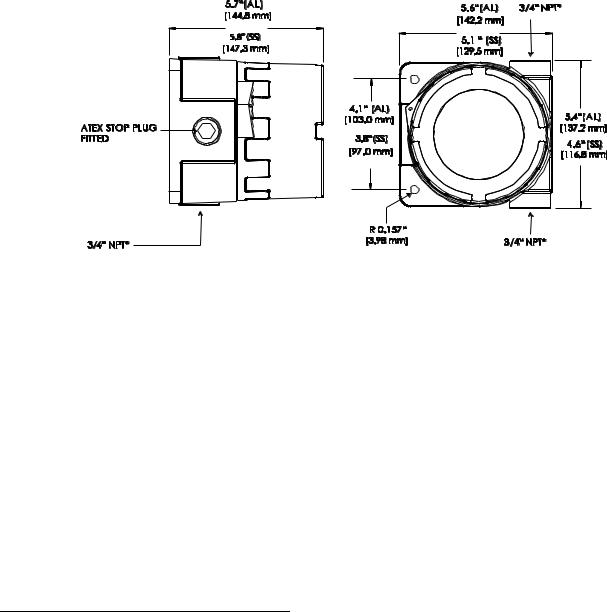
Enclosure Dimensions
The Millennium II Transmitter enclosure is available in Aluminum (AL6061) and Stainless Steel (SS316). Dimensions are in inches and millimeters.
Figure 1: Transmitter Enclosure Dimensional Drawing
* M20, ½” NPT, & ½” BSP threads also available
6
MAN-0076 Rev 05 Millennium II December 07, 2012
Net Safety Monitoring Inc
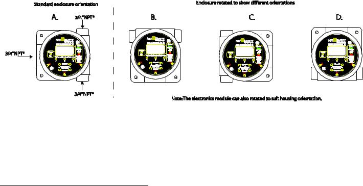
SECTION 1: Installation
1.1 Unpack
Carefully remove all components from the packaging and check them against the enclosed packing list. Inspect all components for obvious damage such as broken or loose parts. If you find any components missing or damaged, notify the representative or Net Safety Monitoring, immediately.
1.2 Mounting
Ensure transmitter and sensor are securely mounted, taking into consideration all requirements. Sensors may be installed directly to transmitters or remotely using a Certified Net Safety junction box. See Figure 11 when mounting sensor remotely.
1.2.1 Transmitter Orientation Option
Depending on the installation and mounting requirements, the transmitter enclosure (housing) may be mounted in different orientations as seen in Figure 2. To accommodate the different mounting orientations, the electronics module can be rotated inside the transmitter enclosure. See Section ‘1.2.3 Rotating electronics module relative to enclosure and conduit entries’ and Figure 4.
NOTE: Ensure the orientation allows proper wiring and adequate wire length inside the transmitter enclosure.
Figure 2: Different enclosure orientations
When determining suitable enclosure orientation for specific application, installers should observe all local regulations and guidelines for mounting enclosures.
* M20, ½” NPT, & ½” BSP threads also available
7
MAN-0076 Rev 05 Millennium II December 07, 2012
Net Safety Monitoring Inc

1.2.2 Transmitter electronics module and Relay options
The transmitter electronics module may be equipped with 4 electromechanical relays or 4 solid-state relays which are mounted to the main terminal board via plastic standoffs. Relay boards are field replaceable by simply unlocking the plastic standoffs with a small flat head screw driver. Remove relay board after unlocking standoffs, insert the replacement relay board, and then lock the plastic standoff with the screw driver. See Figure 3 for relay board description.
Warning  Before wiring or replacement of relay boards, ensure that the power to transmitter is switched off. Do not open the transmitter enclosure in a classified area.
Warning  Avoid touching electronic components, as they are susceptible to electrostatic discharge (ESD).
Refer to Appendix A, “Electrostatic Sensitive Device (ESD)”.
Figure 3: Board assembly diagram
8
MAN-0076 Rev 05 Millennium II December 07, 2012
Net Safety Monitoring Inc
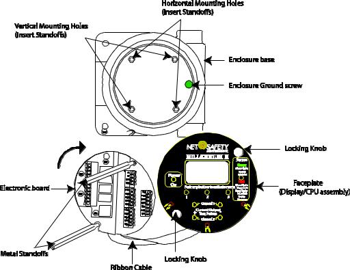
1.2.3 Rotating electronics module relative to enclosure and conduit entries
The electronics module consists of the relay board and faceplate (Display/CPU assembly) with main terminal board. To rotate the electronics module, follow these instructions:
1.Turn off power to transmitter and ensure area is de-classified.
2.Remove the enclosure cover.
3.Unscrew both the locking knobs and free from two metal standoffs.
4.Lift transmitter faceplate from enclosure.
5.Disconnect existing wiring.
6.Unscrew the two metal standoffs using a ¼”hex tool.
7.Carefully remove the electronics module.
8.Rotate the electronics module to desired position.
9.Align metal standoffs with the mounting holes of the electronics module and enclosure base.
10.Insert metal standoffs in the appropriate mounting holes.
11.Tighten metal standoffs with ¼” hex tool to secure electronics module.
12.Reconnect wiring.
13.Replace faceplate, then fit and hand tighten locking knobs to metal standoffs by turning clockwise.
14.Replace enclosure cover.
Warning  Before wiring or rotating electronics, ensure that the power to transmitter is switched off. Do not open the transmitter enclosure in a classified area.
Warning  Avoid touching electronic components, as they are susceptible to electrostatic discharge (ESD).
Refer to Appendix A, “Electrostatic Sensitive Device (ESD)”.
Figure 4: Rotating Electronics module
Note: To access enclosure grounding screw, remove the electronics module by following steps 1-7 above.
9
MAN-0076 Rev 05 Millennium II December 07, 2012
Net Safety Monitoring Inc
SECTION 2: Wiring and installation
2.1 Field Installation
Warning  Wiring codes and regulations may vary. ATEX requires that supply connection wiring must be rated at least 5°C above the maximum ambient temperature of 85°C. Wiring must comply with all applicable regulations relating to the installation of electrical equipment in a hazardous area and is the responsibility of the installer. If in doubt, consult qualified personnel before wiring the system.
Warning  Do not open the transmitter enclosure in a classified area (Do not open when an explosive atmosphere may be present).
Guidelines
The safety ground connection of the transmitter is a Green screw found in the enclosure. See Figure 4 for Ground screw location. Note: The electronics module has to be removed to access Ground screw. Follow steps 1-7 under Section ‘1.2.3 Rotating electronics module relative to enclosure and conduit entries’, when removing electronics module.
If the 4-20mA signal is not used, connect a jumper between the 4 – 20mA terminal and the Common terminal to allow analog current levels to be monitored at the Test Jacks on the faceplate.
The use of shielded cable is highly recommended for signal, input, output and power wires. Refer to Section ‘2.1.2 Cable choice and guidelines’ for recommended cable to help eliminate interference caused by extraneous electrical or electromagnetic ‘noise’. To meet IEC 61000-1 and IEC 61000-4 EMI requirements, follow the recommendations listed under Section ‘2.1.2 Cable choice and guidelines’.
In applications where wiring is installed in conduit, conduit must not be used for wiring to any other electrical equipment.
For effective communication, Net Safety limits sensor separation to 2000 feet using 16AWG wires.
Modbus RS-485 connection 2-wire mode, multipoint serial line available. Up to 247 addresses allowed.
When developing a RS-485 chain of devices, the last device in the chain requires an end of line termination resistor (120 Ohms).
Transmitter connector terminals accommodate wire from 14 to 20 AWG wires.
2.1.1 Seals
Warning  The use of conduit wiring seals is recommended to protect the system against water ingression, and equipment should be installed according to local electrical codes. Seals are especially recommended for installations that use high-pressure or steam cleaning devices in proximity to the transmitter and/or sensor. The cementing material used on the Millennium II sensors is suitable for an operating temperature range of
(-55°C to +85 °C).
Guidelines
It is recommended that explosion-proof drains and conduit breathers be used. In some applications, alternate changes in temperature and barometric pressure can cause ‘breathing’ which allows moist air to enter and circulate inside the conduit. Joints in the conduit system are seldom tight enough to prevent this ‘breathing’.
Threaded connections on the enclosure between the enclosure and conduit pipe need to be sealed with thread tape, such as Teflon tape, or something similar.
Hydrophobic filters (IPF-001) may be used to protect sensors from water.
10
MAN-0076 Rev 05 Millennium II December 07, 2012
Net Safety Monitoring Inc
It is the responsibility of the installer to install conduit seals where necessary, and to design conduit runs to ensure that condensation does not accumulate and collect inside the enclosure.
2.1.2 Cable choice and guidelines
Radio Frequency Interference (RFI) can be caused by nearby electrical devices (transformers, high voltage equipment) as well as handheld communications devices/radios, which when activated, may impede the proper functioning of the transmitter and sensor. Selecting the right instrumentation cable and making proper grounding connections within the junction box will reduce or eliminate interference. Visible symptoms of Radio Frequency Interference (RFI) include inconsistent, incorrect and erratic LEL and PPM readings.
Important Wiring Guidelines
Fire and gas detection instruments are an important part of a safety alarm and shutdown system. The system is composed of:
detection instruments
customer connected equipment
wiring
Net Safety designs and manufactures its detection equipment under rigid quality control management systems and makes every effort to design for the harshest of industrial environments. The other components of the system – the customer-connected equipment and wiring – are also important contributors to the overall quality and performance of the safety system.
It is important to implement wiring that ensures the reliability and integrity of the safety system. Field wiring practices and the choice of cable type specified vary from project to project. Poor practices and choices are often found to be the source of unwanted system disruptions. Radio Frequency Interference (RFI) and Electro-Magnetic Interference (EMI) are usually very powerful disruptive forces in industrial facilities and these forces act upon the system through the wiring.
Follow the wiring specifications and guidelines in this manual carefully. The cable used should be a very high quality instrument grade, certified for the application conditions, consisting of a rugged protective outer jacket, an overall electrical shield of fine braided copper or metallic foil, and internal pairs or triads of foil shielded copper wire of suitable gauge for the power conducted over the specified length.
The shields must be electrically continuous from the instrument junction box through other junction boxes and finally to the connected equipment. The shield must be connected to a suitable ground sink as specified in the instrument manual in order to protect the system from electrical disturbances.
Recommended cable and guidelines
The type of cable and shielding practices are especially important when sensor is separated from transmitter via junction box. Net Safety recommends using CSA armored instrumentation cable (ACIC 2PR 16AWG, 300V, ISOS, PVC) when rigid (steel) conduit is not used. See Figure 5. This cable should be used between the PLC/PANEL/DCS and the Millennium II Transmitter, as well as between the Millennium II Transmitter and junction box.
Additional notes:
In general, communication cables and power cables should not run in parallel for any significant length, and should not be carried in the same cable tray. Through inductance, high currents in power cables can induce significant ‘noise’ in communication cables running parallel alongside power cables.
See cable preparation procedure on next page.
11
MAN-0076 Rev 05 Millennium II December 07, 2012
Net Safety Monitoring Inc
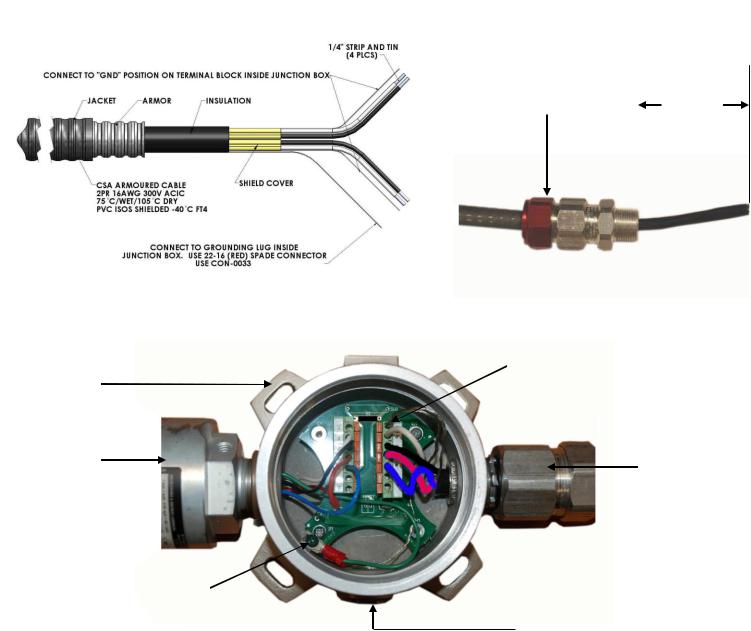
Armored Cable preparation procedure:
1.Prepare the armored instrument cable as illustrated in Figure 5 and follow all assembly and/or preparation instructions provided by the cable and/or cable gland manufacturer.
2.Install cable gland and reducer onto the cable.
3.Ensure four (4) inches of wire length is available for connecting to terminals inside the junction box.
4.Use a small flat head screw driver when connecting wires to connector terminals. See Figure 6.
5.Connect sensor wires to the appropriate terminals. See Figure 5C, Figure 9, Figure 12 and Figure 13.
Figure 5: Cable preparation
|
A: Drawing showing of cable without gland |
B. Picture of cable showing gland and insulation |
|
Hazloc cable gland |
4 Inches |
Net Safety
Junction Box
Millennium II
Sensor
Shield wire from flexible Armored cable and sensor ground wire (Green wire) connected to Earth grounding screw in junction box
C. Picture of cable wired to junction box and sensor
Shield wires from each twisted pair connected to “GND” (Earth Ground) on terminal block.
Cable gland &
Armored cable
¾” NPT stopping plug.
Note: If required, use cable glands which have been approved for hazardous locations.
12
MAN-0076 Rev 05 Millennium II December 07, 2012
Net Safety Monitoring Inc
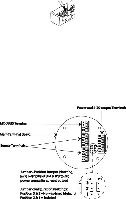
Warning  Before wiring, ensure that power to transmitter is switched off.
When connecting cable wires, use a small screwdriver to gently press down and hold the spring connector open. Insert the appropriate wire into the open connector hole, releasing the screwdriver to secure the wire. See Figure 6.
Figure 6: Connecting wires
Warning  Avoid touching electronic components, as they are susceptible to electrostatic discharge (ESD).
Refer to Appendix A, “Electrostatic Sensitive Device (ESD)”.
2.1.3 Analog output, isolated supply, non-isolated supply and jumper configuration
The analog output may be powered from the main instrument power supply or a separate, independent power supply in which case an isolated wiring configuration is necessary.
To set a Non-isolated or Isolated current output, simply move the Jumpers/shorting jacks (JP3 and JP4) to either the Non-isolated or Isolated current position. For Non-isolated current output, ensure pins 3 & 2 at JP3 & JP4 location on the main terminal board are jumpered (shorted). Factory standard models ship with jumpers at JP3 & JP4 in the Non-isolated current output position (default position).
For Isolated current output, pins 1 & 2 at JP3 & JP4 should be jumpered (shorted). Note that JP3 is for configuring channel 1 and JP4 is for configuring channel 2. Jumpers and pins are located next to the Power and 4- 20 output terminals on the main terminal board. See Figure 7, also Figure 12 & Figure 13 for reference.
Figure 7: NonIsolated and Isolated current jumpers
Warning  Always ensure that JP3 and JP4 jumpers are in the correct position depending on the current output configuration chosen.
13
MAN-0076 Rev 05 Millennium II December 07, 2012
Net Safety Monitoring Inc
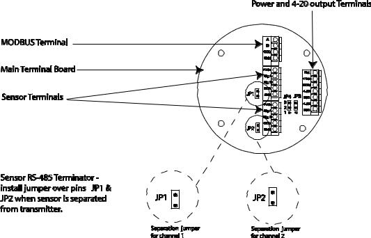
2.1.4 Remotely mounted sensors jumper configuration
Sensor separation from the transmitter may extend up to 2000 feet in which case a junction box is required.
When mounting sensor remotely (separating sensor from transmitter), Jumpers JP1 and JP2 should be installed over the pins. Jumpers and pins are located on the main terminal board near the sensor terminals. JP1 is for channel 1 and JP2 is for channel 2. Refer to Figure 8.
Figure 8: Separation Jumpers positions
Warning  When separating sensor and transmitter, install JP1 and JP2 over pins.
14
MAN-0076 Rev 05 Millennium II December 07, 2012
Net Safety Monitoring Inc

2.1.5 Sensor and Transmitter terminals
Warning  Before wiring, ensure power to the unit is switched off. Connect the sensor wires to the sensor terminals of the transmitter and connect the transmitter’s power and output terminals to the wiring leading to the Power source/panel. Refer to the configuration tables below for sensor as well as transmitter power and output terminal designations.
Table 1: Sensor and Transmitter Terminals
|
Sensor Terminals |
|||
|
Sensor |
Transmitter Sensor Board |
||
|
Wires |
Terminal designation |
||
|
White |
+Vdc(from transmitter) |
||
|
Red |
SigA |
||
|
Blue |
SigB |
||
|
Black |
Com |
||
|
Green |
Earth Ground |
Transmitter Power Terminals
|
Transmitter terminal |
Function |
|
designation |
|
|
RST |
Remote Reset |
|
+Vdc(10.5-32) |
Power(+) |
|
COM |
Power(-) |
|
4-20(CH1) |
Current loop output |
|
ISO(CH1) |
+Vdc isolated 4-20 power |
|
4-20(CH2) |
Current loop output |
|
ISO(CH2) |
+Vdc isolated 4-20 power |
Figure 9: Sensor wiring and terminal connections
15
MAN-0076 Rev 05 Millennium II December 07, 2012
Net Safety Monitoring Inc
Specifications:
|
Accompanying Data:
Emerson Net Safety Millennium II Transmitter PDF Reference Manual (Updated: Monday 26th of December 2022 01:51:54 AM)
Rating: 4.8 (rated by 11 users)
Compatible devices: Rosemount 8712EM, 6081-P, Rosemount 326L, Rosemount 3308A, Micro Motion 2500, Rosemount TCL, Rosemount 3051 CF Series, wirelessHART Rosemount Series.
Recommended Documentation:
Emerson Net Safety Millennium II: Text of Reference Manual
(Ocr-Read Version Summary of Contents, UPD: 26 December 2022)
-
8, Table of Contents Reference Manual June 2016 MAN-0076, Revision 09 Table of Contents II 4.14 Manual reset ………………………………………………………………………………………………… 22 4.15 Self-test relay……………………………………………………………………………………………….. 22 4.16 Sensor upper limi…
-
49, Reference Manual Electrostatic sensitive device MAN-0076, Revision 09 June 2016 Electrostatic sensitive device 39 Section 8: Electrostatic sensitive device Definition: Electrostatic discharge (ESD) is the transfer, between bodies, of an electrostatic charge caused by direct contact or induced by an electrostatic field. The most common cause of ESD is physical contact. Touchi…
-
41, Reference Manual Monitoring and outputs MAN-0076, Revision 09 June 2016 Monitoring and outputs 31 The fault relay is normally energized when no fault conditions are present and is set up for non-latching. The operation of the fault relay is not configurable. The Millennium II transmitter provides various fault conditions to indicate that the transmitter or connected sens…
-
15, Reference Manual Installation MAN-0076, Revision 09 June 2016 Installation 5 Wiring codes and regulations may vary. Wiring must comply with all applicable regulations relating to the installation of electrical equipment in a hazardous area and is the responsibility of the installer. If in doubt, consult a qualified official before wiring the sys…
-
39, Reference Manual Monitoring and outputs MAN-0076, Revision 09 June 2016 Monitoring and outputs 29 Section 6: Monitoring and outputs 6.1 Analog 4-20mA A 4-20 mA current output is used to transmit the transmitter and sensor status and fault codes to other devices. This output can be wired for isolated or non-isolated operation. A 4.0 mA output indicates …
-
40, Monitoring and outputs Reference Manual June 2016 MAN-0076, Revision 09 30 Monitoring and outputs Figure 6-1 Analog/HART wiring 6.3 Relays (Optional) Optional electromechanical relays have Form-C SPDT contacts rated 5 Amps at 30 VDC/ 250 VAC. There are four physical relays; one Fault and three Alarm relays. These relays have Normally Open and Norm…
-
38, Calibration procedure Reference Manual June 2016 MAN-0076, Revision 09 28 Calibration procedure 5.2 Status conditions during calibration Condition Current output LED indication Red Green Relay outputs Fault Alarm Sensor is zeroing itself 3 mA Off Solid Normal state Normal state Sensor is waiting until it detects application of calibration gas 3.3 …
-
35, Reference Manual Calibration procedure MAN-0076, Revision 09 June 2016 Calibration procedure 25 Section 5: Calibration procedure 5.1 Full calibration procedure Prior to attempting calibration read and understand the calibration procedure below. Also see Figure 5-1 for additional reference. The following calibration procedure should be followed to ensure an accur…
-
45, Reference Manual Monitoring and outputs MAN-0076, Revision 09 June 2016 Monitoring and outputs 35 6.7.2 Sensor fault conditions Fault conditions that the various Millennium II sensors detect are as follows: Fault condition SC310 SC311 ST322 ST332 ST340 ST320 ST330 ST341 ST360 Zero calibration failure P P P P P …
-
44, Monitoring and outputs Reference Manual June 2016 MAN-0076, Revision 09 34 Monitoring and outputs The fault detection circuitry does not monitor the operation of external response equipment or external wiring to the transmitter. It is important that external equipment and wiring be checked periodically to ensure they are operational. 6.7 Fault con…
-
51, Reference Manual Specifications MAN-0076, Revision 09 June 2016 Specifications 41 Section 10: Specifications 10.1 Electrical 10.1.1 Operating voltage range 10.5 to 32 VDC 18 to 32 VDC (HART versions only) 10.1.2 Power consumption 2.4 W @ 24 VDC (average — varies by sensor types/quantities) 10.1.3 EMC compliance EN 50270:2006 per EMC d…
-
55, Reference Manual Ordering information MAN-0076, Revision 09 June 2016 Ordering information 45 12.2 M22 dual channel transmitter Model Description M22 Millennium II Dual Channel Transmitter Output Description A Analog Output AD Analog and Digital RS485 Modbus RTU Protocol Outputs AR Analog and Relay Outputs ARD Analog, Relay and Digit…
Emerson Net Safety Millennium II: Recommended Instructions
MZ-5PA064B, PVB98STSS, WX427, HR-J231MS, SVC2340/10, 7535


-
MLP6DSM Transmitter(EFLRMLP6 — Mode 2 & EFLRMLP61 — Mode 1)Instruction Manual | Bedienungsanleitung | Manuel d’utilisation | Manuale di IstruzioniWARNING: Read the ENTIRE instruction manual to become familiar with the features of the product before operating. Failure to operate the product correctly can result in damage to the product, personal property and cause seriou …
MLP6DSM 2
-
Version 2.0 Jun ‟12 © Teradek, LLC 2012. All rights reserved. Page | 1 Setup Guide Contents Introduction…………………………………………………………………………………………………………………………………. 2 Connect and power your devices ……………………………………………………………… …
Bond 13
-
testo 6651 Ethernet · Humidity transmitterstesto 6600 · ProbesP2A software · Parameterizing, adjusting and analyzingsoftware Instruction manual Volume 1 en 1.888.610.7664 [email protected] …
6651 82
-
Sea Tel, Inc. 4030 Nelson Avenue Concord, CA 94520 Tel: (925) 798-7979 Fax: (925) 798-7986 Web: http://www.cobham.com/seatel Sea Tel Europe Unit 1, Orion Industrial Centre Wide Lane, Swaythling Southampton, UK S0 18 2HJ Tel: 44 (0)23 80 671155 Fax: 44 (0)23 80 671166 Web: http://www.cobham.com/seatel Sea Tel Inc is also doing business as Cobham SATCOM — Maritime Nove …
4012 GX KU-BAND 314
-
AOMWAY 1 RC Vision System Nexus V2 Full HD Digital Link User Manual V 1.0 Please read through this manual before use, thank you! www.aomway.com …
Nexus V2 9
-
Non-contact Radar (FMCW) Level Meter for solidsfor distance, level, volume and mass measurement of solidsOPTIWAVE 6300 COPTIWAVE 6300 COPTIWAVE 6300 COPTIWAVE 6300 CHandbookHandbookHandbookHandbook© KROHNE 04/2011 — 4000547003 — HB OPTIWAVE 6300 R03 en …
OPTIWAVE 6300 C 128
-
Three Button transmitter:G3T-A Programming InstructionsWARNINGMoving Door can cause serious injury or death.• Wall Console must be mounted in sight of door, at least 5 feet above fl oor and clear of moving door parts.• Keep people clear of opening while door is moving.• Do NOT allow children to play with the Remote or door opener.If safety reverse does not work properly: • Close …
G3T-A 2
-
QUICK START GUIDEGUIDE DE DÉMARRAGE RAPIDEGUÍA DE INICIO RÁPIDO NY-GS10020103020103For additional product information, please consult the manual at:Pour plus de renseignements sur le produit, consultez le manuel à:Para más información sobre el producto, consulte el manual en:NYRIUS.COM/SUPPORT4 3 2 1REMOTE ON A BIRTRANSMITTER4 3 2 1VIDEO INAUDIO INLEFT RIGHTDC 12VTRANS …
NY-GS10 2
-
Xantech XtraLink™ IP — Quick Start Guide The Xantech XtraLink™ IP is a fully functional stand-alone IP-to-serial remote access controller with internal web server. In addition, it functions as a remote expansion port for the XANTECH series of IP-based control systems. Featuring an RS-232/422/485 port, a POE ca …
XTRALINK IP 4
-
3.885.5275.200Ed. 1.1 IT — 2012© Copyright 2010E X P E R T I S E S O L U T I O N S S U S T A I N A B I L I T Y1. Safetyinformation2. Technicalinformation3. Commissioning4. Troubleshooting5. Maintenance6. SparepartsTorque Tube TB300Digital TransmittersInstallation and Maintenance InstructionsThe PED Directive 97/23/EC is repealed and replaced by the new PED Directive 2014/6 …
TB300 24
Additional Information:
Operating Impressions, Questions and Answers:
Назначение
Датчики горючих и токсичных газов Millennium II, Millennium II Basic предназначены для измерений довзрывоопасных концентраций горючих газов, объемной доли оксида углерода, кислорода и сероводорода в воздухе рабочей зоны, а также сигнализации о достижении заданных пороговых значений и передачи измерительной информации внешним устройствам.
Описание
Датчики горючих и токсичных газов Millennium II, Millennium II Basic (далее — датчики) являются стационарными одно- или двухканальными приборами непрерывного действия.
Конструктивно датчики состоят из блока трансмиттера и подключаемого к нему блока сенсора (одного или двух). Сенсор может подключаться как непосредственно в оболочку трансмиттера, так и удаленно (до 600 м) в соединительную коробку. Информационный обмен между блоками сенсора и трансмиттера осуществляется в цифровой форме, интерфейс RS485.
Корпус трансмиттера выполнен из алюминия или нержавеющей стали и состоит из нижней части, винтовой крышки со смотровым окном и блока управления типа TX-M2a-b, расположенного внутри. Блок электроники имеет модульную структуру и может оснащаться дополнительными платами (HART, релейный выход и т.д.) Управление режимами работы датчика осуществляется механическими кнопками блока электроники (при снятой крышке, вне взрывоопасной зоны) или бесконтактно с помощью специального магнитного инструмента. Подключение сенсора и кабельных вводов осуществляется резьбовым соединением %» NPT (3X). Датчик выпускается в трех основных исполнениях:
1) Millennium II, обозначение M21-b-c-EM — одноканальный с OLED дисплеем;
2) Millennium II, обозначение M22-b-c-EM — двухканальный с OLED дисплеем;
3) Millennium II Basic, обозначение M2B-b-c-EM — одноканальный без дисплея..
Символы “b” в обозначении исполнения указывают на вид выходного сигнала датчика (A — аналоговый 4-20 мА, R — релейный, S — твердотельное реле, D — цифровой RS485 Modbus™ RTU, H — HART, и их комбинации), символ “c” — материал корпуса (A — алюминий марки 6061, S — нержавеющая сталь марки 316).
В состав датчика входят сенсоры, перечисленные в таблице 1.
Таблица 1
|
Обозначение сенсора |
Определяемый компонент |
Принцип измерений |
|
SC311x-100-ASSY-EM |
Горючие газы и пары горючих жид-костей (см. таблицу 4) |
Оптический недисперсионный инфракрасный (NDIR) |
|
SC310x-100-ASSY-EM |
Г орючие газы и пары горючих жид-костей (см. таблицу 5) |
Т ермокаталитический |
|
ST320x-y-ASSY-EM |
Сероводород (H2S) |
Электрохимический |
|
ST341x-y-ASSY-EM |
Кислород (O2) |
Электрохимический |
|
ST360x-y-ASSY-EM |
Оксид углерода (CO) |
Электрохимический |
|
Примечание — знак «x» в обозначении сенсора указывает на материал корпуса (A -алюминий марки 6061, S — нержавеющая сталь марки 316), знак «у» — на диапазон показаний. |
Датчики могут комплектоваться универсальным набором для установки в газоходы (UDM-001 и UDM-002).
Способ отбора пробы — диффузионный.
Датчики обеспечивают выходные сигналы (в зависимости от модификации):
— показания встроенного светодиодного дисплея (кроме M2B-b-c-EM);
— светодиодная индикация (для M2B-b-c-EM — норма / отказ / порог, для M21-b-c-EM и M22-b-c-EM
— питание / состояние);
— унифицированный аналоговый выходной токовый сигнал постоянного тока (4-20) мА (кроме M2B-R и M2B-D);
— цифровой RS485, протокол Modbus™ RTU (по заказу);
— 4 релейных выхода типа «сухой контакт» (по заказу);
— цифровой HART (по заказу).
Датчик обеспечивает выполнение следующих основных функций (в зависимости от модификации):
— непрерывное измерение содержания определяемых компонентов;
— формирование унифицированного выходного аналогового токового сигнала постоянного тока (4 — 20) мА;
— формирование выходного цифрового сигнала RS-485, протокол Modbus™ RTU;
— формирование релейных выходных сигналов;
— формирование цифрового сигнала HART.
Датчики выполнены во взрывозащищенном исполнении вид взрывозащиты «взрывонепроницаемая оболочка», маркировка взрывозащиты:
— трансмиттер M21-b-c-EM, M22-b-c-EM, M2B-b-c-EM 1Ex d IIB+H2 T5 Gb X
— блок управления TX-M2a-b 2Ex nA nC IIC T5 Gc X
— сенсор SC31xy-z-ASYY-EM 1Ex d IIB+H2 T5 Gb X
— сенсор ST3xxy-z-ASYY-EM 1Ex d IIB+H2 T5 Gb X
— коробка распределительная серии JB 1Ex d IIB+H2 T5 Gb X
Степень защиты от внешних воздействий по ГОСТ 14254-96 не ниже IP64.
Датчики могут применяться в качестве самостоятельных измерительных преобразователей, а также в составе измерительных систем утвержденного типа, допущенных к применению на территории РФ. Пломбирование датчиков изготовителем не предусмотрено. Внешний вид датчиков приведен на рисунках 1 — 4.
Программное обеспечение
Датчики имеют встроенное программное обеспечение (далее — ПО), разработанное изготовителем специально для решения задач измерения содержания определяемых компонентов (соответственно исполнению).
ПО датчиков обеспечивает следующие основные функции (в зависимости от модификации датчика):
— обработку и передачу измерительной информации от первичного измерительного преобразователя;
— формирование выходного аналогового сигнала (4 — 20) мА;
— формирование цифрового выходного сигнала RS485, HART;
— формирование релейных выходных сигналов;
— самодиагностику аппаратной части датчика;
— настройку нулевых показаний и чувствительности датчика.
ПО датчика реализует следующие расчетные алгоритмы:
1) вычисление значений содержания определяемого компонента по данным от первичного измерительного преобразователя;
2) вычисление значений выходного аналогового сигнала и цифрового HART;
3) сравнение текущих результатов измерений с заданными пороговыми уровнями срабатывания сигнализации;
4) непрерывную самодиагностику аппаратной части датчика.
ПО датчиков идентифицируется посредством отображения номера версии на дисплее по запросу через меню датчика (для M21-b-c-EM и M22-b-c-EM) или по наклейке на плате блока управления (для M2B-b-c-EM).
Идентификационные данные программного обеспечения приведены в таблицах 2 — 4.
Таблица 2 — Идентификационные данные ПО для модификации M21-b-c-EM
|
Идентификационные данные (признаки) |
Значение |
|||||
|
Идентификационное наименование ПО |
FRM-0120 (для M21-ARD-A/S-EM) |
FRM-0122 (для M21-AD-A/S-EM) |
FRM-0124 (для M21-AR-A/S-EM, M21-ARS-A/S-EM) |
FRM-0126 (для M21-A-A/S-EM) |
FRM-0138 (для M21-AH-A/S-EM) |
FRM-0139 (для M21-AHR-A/S) -EM |
|
Номер версии (идентификацион ный номер) ПО |
2.2 |
2.2 |
2.2 |
2.2 |
2.2 |
2.2 |
|
Цифровой идентиф икатор ПО |
b2a2f4cdc cde9a1234 3ea0a04d3 3082f |
f274cd53e e4755eb3d 18598537 daee36 |
000f849ce b8ee52f68 ea878058b 7cdea |
b97b75a9d cf9fd3061 031874e3d 73b3a |
c626a8621 b0fc7edc7 0d34a0d3a 197f5 |
a8653ed90 109456ade 4079c027c 385f2 |
|
Алгоритм получения цифрового идентификатора |
MD5 |
MD5 |
MD5 |
MD5 |
MD5 |
MD5 |
|
Примечание — номер версии П контрольных сумм, указанные (firmware) указанных версий. |
О должен быть не ниже указанного в таблице. Значения в таблице, относятся только к файлам встроенного ПО |
Таблица 3 — Идентификационные данные ПО для модификации M22-b-c-EM
|
Идентификационные данные (признаки) |
Значение |
|||
|
Идентификационное наименование ПО |
FRM-0117 (для M22-ARD-A/S- EM) |
FRM-0121 (для M22-AD-A/S- EM) |
FRM-0123 (для M22-AR-A/S-EM, M22-ARS-A/S) -EM |
FRM-0125 (для M22-A-A/S- EM) |
|
Номер версии (идентификацион ный номер) ПО |
2.2 |
2.2 |
2.2 |
2.2 |
|
Цифровой идентиф икатор ПО |
07442363d196c21 fb357aa7fa278495 d |
5da2c818ce14b2 947bef1918cdef 21be |
8301660268527c0 7d0817c28d3c45e 08 |
338d1585638ec ad9f4dcc01225 c1431e |
|
Алгоритм получения цифрового идентификатора |
MD5 |
MD5 |
MD5 |
MD5 |
|
Примечание — номер версии ПО должен быть не ниже указанного в таблице. Значения контрольных сумм, указанные в таблице, относятся только к файлам встроенного ПО (firmware) указанных версий. |
Таблица 4 — Идентификационные данные ПО для модификации M2B-b-c-EM
|
Идентификационные данные (признаки) |
Значение |
||
|
Идентификационное наименование ПО |
FRM-0141 (для M2B-AH-A/S-EM, M2B-AHR-A/S-EM) |
FRM-0142 (для M2B-D-A/S-EM) |
FRM-0143 (для M2B-R-A/S-EM) |
|
Номер версии (идентификационный номер) ПО |
1.0 |
1.0 |
1.0 |
|
Цифровой идентиф икатор ПО |
fe626425c866815382a5 f7d6760c5476 |
4604a9bc0bd9db66d57d c9fda9da22a7 |
2e0ccf7df2f8bf04e29e5 50d1c8e31e3 |
|
Алгоритм получения цифрового идентификатора |
MD5 |
MD5 |
MD5 |
|
Примечание — номер версии ПО должен быть не ниже указанного в таблице. Значения контрольных сумм, указанные в таблице, относятся только к файлам встроенного ПО (firmware) указанных версий. |
Влияние встроенного программного обеспечения учтено при нормировании метрологических характеристик датчиков.
Датчики имеют защиту встроенного программного обеспечения от преднамеренных или непреднамеренных изменений. Уровень защиты — «средний» по Р 50.2.077—2014.
Технические характеристики
Диапазоны измерений, пределы допускаемой основной погрешности для датчиков приведены в таблицах 5 — 7.
Таблица 5 — Датчики с оптическим сенсором типа SC311x-100-ASSY-EM
|
Определяемый компонент |
Диапазон показаний |
Диапазон измерений |
Пределы допускаемой основной погрешности 3) |
|||
|
% НКПР 2) |
Объемной доли, % |
|||||
|
абсолютной, % НКПР |
относи тельной, % |
приведённой, 1) % |
||||
|
метан (СН4) |
от 0 до 100 % НКПР |
от 0 до 50 включ. |
от 0 до 2,2 включ. |
±5 |
— |
— |
|
св. 50 до 100 |
св. 2,2 до 4,4 |
— |
±10 |
— |
||
|
метан (СН4) |
от 0 до 100 % (об. д.) |
от 0 до 50 включ. |
— |
— |
±5 |
|
|
св. 50 до 100 |
— |
±10 |
— |
|||
|
этан (C2H6) |
от 0 до 100 % НКПР |
от 0 до 50 включ. |
от 0 до 1,25 включ. |
±5 |
— |
— |
|
св. 50 до 100 |
св. 1,25 до 2,5 |
— |
±10 |
— |
||
|
пропан (СзН8) |
от 0 до 100 % НКПР |
от 0 до 50 включ. |
от 0 до 0,85 включ. |
±5 |
— |
— |
|
св. 50 до 100 |
св. 0,85 до 1,7 |
— |
±10 |
— |
||
|
у 1 т 0 £3 w л |
от 0 до 100 % НКПР |
от 0 до 50 включ. |
от 0 до 0,7 включ. |
±5 |
— |
— |
|
св. 50 до 100 |
св. 0,7 до 1,4 |
— |
±10 |
— |
||
|
изобутан (и-С4НШ) |
от 0 до 100 % НКПР |
от 0 до 50 включ. |
от 0 до 0,65 включ. |
±5 |
— |
— |
|
св. 50 до 100 |
св. 0,65 до 1,3 |
— |
±10 |
— |
||
|
пентан (С5Н12) |
от 0 до 100 % НКПР |
от 0 до 50 включ. |
от 0 до 0,7 включ. |
±5 |
— |
— |
|
св. 50 до 100 |
св. 0,7 до 1,4 |
— |
±10 |
— |
||
|
гексан (С6Н14) |
от 0 до 100 % НКПР |
от 0 до 50 включ. |
от 0 до 0,5 включ. |
±5 |
— |
— |
|
св. 50 до 100 |
св. 0,5 до 1,0 |
— |
±10 |
— |
||
|
этилен (С2Н4) |
от 0 до 100 % НКПР |
от 0 до 50 включ. |
от 0 до 1,15 включ. |
±5 |
— |
— |
|
св. 50 до 100 |
св. 1,15 до 2,3 |
— |
±10 |
— |
||
|
пропилен (С3Н6) |
от 0 до 100 % НКПР |
от 0 до 50 включ. |
от 0 до 1,0 включ. |
±5 |
— |
— |
|
св. 50 до 100 |
о д с, в.,0 с2 |
— |
±10 |
— |
||
|
бензол (С6Н6) |
от 0 до 100 % НКПР |
от 0 до 50 включ. |
от 0 до 0,6 включ. |
±5 |
— |
— |
|
св. 50 до 100 |
св. 0,6 до 1,2 |
— |
±10 |
— |
|
Определяемый компонент |
Диапазон показаний |
Диапазон измерений |
Пределы допускаемой основной погрешности 3) |
|||
|
% НКПР 2) |
Объемной доли, % |
|||||
|
абсолютной, % НКПР |
относи тельной, % |
приведённой, 1) % |
||||
|
оксид этилена (C2H4O) |
от 0 до 100 % НКПР |
от 0 до 50 включ. |
от 0 до 1,3 включ. |
±5 |
— |
— |
|
св. 50 до 100 |
о д со в.,6 с2 |
— |
±10 |
— |
||
|
изо-пентан O-C5H12) |
от 0 до 100 % НКПР |
от 0 до 50 включ. |
от 0 до 0,7 включ. |
±5 |
— |
— |
|
св. 50 до 100 |
св. 0,7 до 1,4 |
— |
±10 |
— |
||
|
Ацетон ((СНз)2СО) |
от 0 до 100 % НКПР |
от 0 до 50 |
от 0 до 1,25 |
±5 |
— |
— |
|
1,3-бутадиен (С4Н6) |
от 0 до 100 % НКПР |
от 0 до 50 включ. |
от 0 до 0,7 включ. |
±5 |
— |
— |
|
св. 50 до 100 |
св. 0,7 до 1,4 |
— |
±10 |
— |
||
|
диметило-вый эфир ((СНз)2О) |
от 0 до 100 % НКПР |
от 0 до 50 включ. |
от 0 до 1,35 включ. |
±5 |
— |
— |
|
св. 50 до 100 |
св. 1,35 до 2,7 |
— |
±10 |
— |
||
|
Сумма углеводородов СхНу (поверочный компонент -метан) |
от 0 до 100 % НКПР |
от 0 до 50 |
±5 |
|||
|
Сумма углеводородов СхНу (поверочный компонент -гексан) |
от 0 до 100 % НКПР |
от 0 до 50 |
±5 |
|||
|
Примечания: 1) Погрешность приведена к верхнему значению поддиапазона измерений. 2) Значения НКПР горючих газов и паров горючих жидкостей указаны в соответствии с ГОСТ 30852.19-2002. 3) Ввиду того, что датчики обладают чувствительностью к широкой номенклатуре органических веществ помимо указанных, пределы допускаемой основной погрешности датчиков нормированы только для смесей, содержащих только один горючий компонент. |
Таблица 6 — Датчики с термокаталитическим сенсором типа SC310x-100-ASSY-EM
|
Определяемый компонент 2) |
Диапазон измерений |
Пределы допускаемой основной абсолютной погрешности, % НКПР |
|
|
% НКПР 1) |
Объемной доли, % |
||
|
метан (СН4) |
от 0 до 50 |
от 0 до 2,2 |
±5 |
|
этан (С2Н6) |
от 0 до 50 |
от 0 до 1,25 |
±5 |
|
этилен (С2Н4) |
от 0 до 50 |
от 0 до 1,15 |
±5 |
|
пропан (С3Н8) |
от 0 до 50 |
от 0 до 0,85 |
±5 |
|
Определяемый компонент 2) |
Диапазон измерений |
Пределы допускаемой основной абсолютной погрешности, % НКПР |
|
|
% НКПР 1) |
Объемной доли, % |
||
|
н-бутан (С4Н10) |
от 0 до 50 |
от 0 до 0,7 |
±5 |
|
н-пентан (С5Н12) |
от 0 до 50 |
от 0 до 0,7 |
±5 |
|
гексан (С6Н14) |
от 0 до 50 |
от 0 до 0,5 |
±5 |
|
пропилен (С3Н6) |
от 0 до 50 |
от 0 до 1,0 |
±5 |
|
бензол (С6Н6) |
от 0 до 50 |
от 0 до 0,6 |
±5 |
|
водород (Н2) |
от 0 до 50 |
от 0 до 2,0 |
±5 |
|
метанол (СН3ОН) |
от 0 до 50 |
от 0 до 2,75 |
±5 |
|
этанол (С2Н5ОН) |
от 0 до 50 |
от 0 до 1,55 |
±5 |
|
толуол (С6Н5-СН3) |
от 0 до 50 |
от 0 до 0,55 |
±5 |
|
ацетилен (С2Н2) |
от 0 до 50 |
от 0 до 1,15 |
±5 |
|
изобутан (и-С4Н10) |
от 0 до 50 |
от 0 до 0,65 |
±5 |
|
изо-пентан (i-C5H12) |
от 0 до 50 |
от 0 до 0,7 |
±5 |
|
ацетон ((CH3)2CO) |
от 0 до 50 |
от 0 до 1,25 |
±5 |
|
1,3-бутадиен (C4H6) |
от 0 до 50 |
от 0 до 0,7 |
±5 |
|
диметиловый эфир((СНэ)2О) |
от 0 до 50 |
от 0 до 1,35 |
±5 |
|
винилхлорид (C2H3C1) |
от 0 до 50 |
от 0 до 1,8 |
±5 |
|
аммиак (NH3) |
от 0 до 50 |
от 0 до 7,5 |
±5 |
|
Сумма углеводородов СхНу (поверочный компонент — метан) |
от 0 до 50 |
±5 |
|
|
Сумма углеводородов СхНу (поверочный компонент — гексан) |
от 0 до 50 |
±5 |
|
|
Примечания: 1) Значения НКПР горючих газов и паров горючих жидкостей указаны в соответствии с ГОСТ 30852.19-2002. 2) Ввиду того, что датчики обладают чувствительностью к широкой номенклатуре органических и неорганических горючих веществ, пределы допускаемой основной погрешности нормированы только для смесей, содержащих только один горючий компонент. Диапазон показаний по всем определяемым компонентам от 0 до 100 % НКПР. |
Таблица 7 — Датчики с сенсорами на токсичные газы и кислород (ST3xxy-z-ASSY-
|
Определяемый компонент |
Диапазон показаний объемной доли |
Диапазон измерений объемной доли |
Пределы допускаемой основной погрешности |
Обозна чение сенсора |
||
|
Абсолют ной |
относи тельной, % |
приведённой, 2) % |
||||
|
сероводород (H2S) |
от 0 до 50 -1 млн |
от 0 до 10 млн-1 включ |
±2 млн-1 |
— |
||
|
св. 10 до 50 -1 млн |
— |
±20 |
— |
|||
|
сероводород (H2S) 1) |
от 0 до 100 -1 млн |
от 0 до 100 -1 млн |
±15 |
ST320x- 100- ASSY- EM |
||
|
кислород (O2) |
от 0 до 25 % |
от 0 до 25 % |
±1 % |
ST341x- 25-ASSY- EM |
||
|
оксид углерода (СО) 1) |
от 0 до 500 -1 млн |
от 0 до 100 млн-1 включ |
±15 млн-1 |
— |
ST360x- 1000- ASSY— EM |
|
|
Св. 100 до 500 млн-1 |
— |
±15 |
— |
|||
|
от 0 до 1000 млн-1 |
от 0 до 1000 -1 млн |
±10 |
||||
|
Примечание — 1) — используются для измерения объемной доли определяемого компонента при аварийных ситуациях. 2) погрешность приведена к верхнему значению поддиапазона измерений |
Таблица 8
|
Наименование параметра |
Значение |
|
Предел допускаемой вариации выходного сигнала датчика, в долях от предела допускаемой основной погрешности |
0,5 |
|
Предел допускаемого изменения показаний при непрерывной работе в течение 8 ч, в долях от предела допускаемой основной погрешности |
0,5 |
|
Пределы допускаемой дополнительной погрешности от изменения температуры окружающей среды на каждые 10 oC в диапазоне рабочих условий эксплуатации, в долях от предела допускаемой основной погрешности |
0,2 |
|
Пределы допускаемой дополнительной погрешности от влияния изменения относительной влажности окружающей среды в диапазоне от 60 до 0 % и от 60 до 99 %, в долях от предела допускаемой основной погрешности |
0,5 |
|
Пределы допускаемой дополнительной погрешности от влияния изменения атмосферного давления в пределах рабочих условий на каждые 3,3 кПа, в долях от предела допускаемой основной погрешности |
0,2 |
|
Время прогрева датчика, с, не более |
90 |
|
Электрическое питание датчиков осуществляется постоянным током напряжением, В — исполнение с аналоговым/HART выходом — прочие |
от 18 до 32 от 10,5 до 32,0 |
|
Потребляемая мощность, Вт, не более |
5 |
|
Средняя наработка на отказ для электрохимических и термокаталитических датчиков, ч |
40000 |
|
Средняя наработка на отказ для оптических датчиков, ч |
60000 |
Предел допускаемого времени установления выходного сигнала датчика Т0,9д в зависимости от сенсора приведен в таблице 9.
Таблица 9
|
Обозначение сенсора |
Определяемый компонент |
Предел допускаемого времени установления выходного сигнала датчика Т0,9д, с |
|
SC311x-100-ASSY-BM |
Г орючие газы и пары |
11 |
|
SC310x-100-ASSY-BM |
Г орючие газы и пары |
30 |
|
ST320x-100-ASSY-BM |
Сероводород (H2S) |
36 |
|
ST341x-25-ASSY-ЕМ |
Кислород (О2) |
30 |
|
ST360x-1000-ASSY- ЕМ |
Оксид углерода (CO) |
30 |
Габаритные размеры и масса элементов датчика указаны в таблице 10.
Таблица 10
|
Обозначение составной части датчика |
Г абаритные размеры (включая сенсор), мм, не бо лее |
Масса, кг, не более |
||
|
Ширина |
Высота |
Г лубина |
||
|
M21-b-A, M22-b-A-EM |
160 |
246 |
152 |
2,41) |
|
M21-b-S, M22-b-S-EM |
150 |
226 |
152 |
2,61) |
|
M2B-b-A-EM |
122 |
229 |
84 |
0,81) |
|
M2B-b-S-EM |
119 |
226 |
81 |
1,61) |
|
SC310A-100-ASSY- EM, SC311A-100-ASSY- EM, ST3xxA-y-ASSY- EM |
66 |
109 |
66 |
0,4 |
|
SC310S-100-ASSY- EM, SC311S-100-ASSY-EM ST3xxS-y-ASSY- EM |
66 |
109 |
66 |
1,4 |
|
Примечание — 1) Масса блока трансмиттеров указана без учета массы устанавливаемого блока сенсоров. |
Условия эксплуатации
Рабочие условия эксплуатации датчиков приведены в таблице 11.
|
Обозначение |
Диапазон температуры окружающей и анализируемой О/’ч сред, C |
Диапазон относительной влажности окружающей среды при температуре +35 oC, % |
Диапазон атмосферного давления, кПа |
|
Трансмиттер M2B-b-c-EM |
от -60 до +85 |
От 0 до 95 |
От 80 до 120 |
|
Трансмиттер M21-b-c-EM, Трансмиттер M22-b-c-EM |
от -60 до +85 |
От 0 до 99 |
|
|
SC311x-100-ASSY-EM |
от -60 до +85 |
От 0 до 99 |
|
|
SC310x-100-ASSY-EM |
от -60 до +85 |
От 0 до 99 |
|
|
ST341x-25-ASSY-EM |
от -40 до +85 |
От 5 до 99 |
|
|
ST320x-100-ASSY-EM |
от -40 до +85 |
От 5 до 99 |
|
|
ST360x-1000-ASSY- EM |
от -40 до +85 |
От 5 до 99 |
Знак утверждения типа
наносится на лицевую сторону корпуса датчика методом наклейки и на титульный лист Руководства по эксплуатации типографским методом.
Комплектность
Комплект поставки датчиков приведен в таблице 12.
Таблица 12
|
Наименование |
Количество |
|
Датчик горючих и токсичных газов Millennium II или Millennium IIBasic (сенсор по заказу) |
1 шт. |
|
Магнит для настройки датчика |
1 шт. |
|
Комплект универсальный для установки в газоходы (UDM-001 и UDM-002) |
По заказу |
|
Комплект запасных частей |
1 компл. |
|
Руководство по эксплуатации |
1 экз. |
|
Методика поверки МП-001-04/2017 |
1 экз. |
Поверка
осуществляется по документу МП-001-04/2017 «Датчики горючих и токсичных газов Millennium II, Millennium II Basic. Методика поверки», разработанному и утвержденному ООО «ПРОММАШ ТЕСТ» 12.04.2017 г.
Основные средства поверки:
— азот газообразный особой чистоты сорт 2 по ГОСТ 9293-74 в баллоне под давлением;
— стандартные образцы состава газовые смеси выпускаемые по ТУ 6-16-2956-92 в баллонах под давлением ГСО №№ 10256-2013, 10243-2013, 10263-2013, 10245-2013, 10332-2013, 10364-2013, 10334-2013, 10247-2013, 10249-2013, 10367-2013, 10383-2013, 10363-2013, 10385-2013, 103882013, 10384-2013, 10257-2013, 10244-2013, 10248-2013, 10263-2013, 10246-2013, 10365-2013, 9766-2011, 10250-2013, 10366-2013, 10325-2013, 10386-2013, 10333-2013, 10365-2013, 103852013, 10389-2013, 10384-2013, 10549-2014, 10327-2013, 10329-2013, 10253-2013, 10260-2013
— рабочий эталон 1-го разряда генератор газовых смесей ГГС-03-03 (регистрационный номер 65151-15) в комплекте со стандартными образцами газовых смесей в баллонах под давлением
M)
|
Определяемый компонент |
Диапазон показаний объемной доли |
Диапазон измерений объемной доли |
Пределы допускаемой основной погрешности |
Обозна чение сенсора |
||
|
Абсолют ной |
относи тельной, % |
приведённой, 2) % |
||||
|
сероводород (H2S) |
от 0 до 20 -1 млн |
от 0 до 10 млн-1 включ |
±2 млн-1 |
— |
ST320x- 100- ASSY- EM |
|
|
св. 10 до 20 -1 млн |
— |
±20 |
— |
Допускается применение аналогичных средств поверки, обеспечивающих определение метрологических характеристик поверяемых СИ с требуемой точностью.
Знак поверки наносится на свидетельство о поверке.
Сведения о методах измерений
приведены в эксплуатационной документации
Нормативные документы
ГОСТ Р 52350.29-1-2010 Взрывоопасные среды. Часть 29-1. Газоанализаторы. Общие технические требования и методы испытаний газоанализаторов горючих газов
ГОСТ 13320-81 Газоанализаторы промышленные автоматические. Общие технические условия
ГОСТ Р 52931-2008 Приборы контроля и регулирования технологических процессов. Общие технические условия
ГОСТ 8.578-2014 ГСИ Государственная поверочная схема для средств измерений содержания компонентов в газовых средах
Техническая документация изготовителя «Rosemount Inc.», США
ОПИСАНИЕ ТИПА СРЕДСТВА ИЗМЕРЕНИЙ Датчики горючих и токсичных газов Millennium II, Millennium II Basic Назначение средства измерений
Датчики горючих и токсичных газов Millennium II, Millennium II Basic предназначены для измерения довзрывоопасных концентраций горючих газов, объемной доли оксида углерода, кислорода и сероводорода в воздухе рабочей зоны, а также сигнализации о достижении заданных пороговых значений и передачи измерительной информации внешним устройствам.
Описание
Датчики горючих и токсичных газов Millennium II, Millennium II Basic (далее — датчики) являются стационарными одно- или двухканальными приборами непрерывного действия.
Конструктивно датчики состоят из блока трансмиттера и подключаемого к нему блока сенсора (одного или двух). Сенсор может подключаться как непосредственно в оболочку трансмиттера, так и удаленно (до 600 м) в соединительную коробку. Информационный обмен между блоками сенсора и трансмиттера осуществляется в цифровой форме, интерфейс RS485.
Корпус трансмиттера выполнен из алюминия или нержавеющей стали и состоит из нижней части, винтовой крышки со смотровым окном и блока управления типа TX-M2a-b, расположенного внутри. Блок электроники имеет модульную структуру и может оснащаться дополнительными платами (HART, релейный выход и т.д.) Управление режимами работы датчика осуществляется механическими кнопками блока электроники (при снятой крышке, вне взрывоопасной зоны) или бесконтактно с помощью специального магнитного инструмента. Подключение сенсора и кабельных вводов осуществляется резьбовым соединением %» NPT (3X).
Датчик выпускается в трех основных исполнениях:
1) Millennium II, обозначение M21-b-c — одноканальный с OLED дисплеем;
2) Millennium II, обозначение M22-b-c — двухканальный с OLED дисплеем;
3) Millennium II Basic, обозначение M2B-b-c — одноканальный без дисплея..
Символы “b” в обозначении исполнения указывают на вид выходного сигнала датчика
(A — аналоговый 4-20 мА, R — релейный, S — твердотельное реле, D — цифровой RS485 Modbus™ RTU, H — HART, и их комбинации), символ “c” — материал корпуса (A — алюминий марки 6061, S — нержавеющая сталь марки 316).
В состав датчика входят сенсоры, перечисленные в таблице 1.
Таблица 1
|
Обозначение сенсора |
Определяемый компонент |
Принцип измерений |
|
SC311x-100-ASSY |
Горючие газы и пары горючих жидкостей (см. таблицу 4) |
Оптический недисперсионный инфракрасный (NDIR) |
|
SC310x-100-ASSY |
Горючие газы и пары горючих жидкостей (см. таблицу 5) |
Т ермокаталитический |
|
ST320x-y-ASSY |
Сероводород (H2S) |
Электрохимический |
|
ST341x-y-ASSY |
Кислород (O2) |
-//- |
|
ST360x-y-ASSY |
Оксид углерода (CO) |
-//- |
|
Примечание — знак «x» в обозначении сенсора указывает на материал корпуса (A — алюминий марки 6061, S — нержавеющая сталь марки 316), знак «у» — на диапазон показаний. |
Датчики могут комплектоваться универсальным набором для установки в газоходы (UDM-001 и UDM-002).
Способ отбора пробы — диффузионный.
Датчики обеспечивают выходные сигналы (в зависимости от модификации):
— показания встроенного светодиодного дисплея (кроме M2B-b-c);
— светодиодная индикация (для M2B-b-c — норма / отказ / порог, для M21-b-c и M22-b-c
— питание / состояние);
— унифицированный аналоговый выходной токовый сигнал постоянного тока (4-20) мА (кроме M2B-R и M2B-D);
— цифровой RS485, протокол Modbus™ RTU (по заказу);
— 4 релейных выхода типа «сухой контакт» (по заказу);
— цифровой HART (по заказу).
Датчик обеспечивает выполнение следующих основных функций (в зависимости от модификации):
— непрерывное измерение содержания определяемых компонентов;
— формирование унифицированного выходного аналогового токового сигнала постоянного тока (4 — 20) мА;
— формирование выходного цифрового сигнала RS-485, протокол Modbus™ RTU;
— формирование релейных выходных сигналов;
— формирование цифрового сигнала HART.
Датчики выполнены во взрывозащищенном исполнении вид взрывозащиты «взрывонепроницаемая оболочка», маркировка взрывозащиты:
— трансмиттер M21-b-c, M22-b-c, M2B-b-c 1Ex d TTB+H2 T5 Gb X
— блок управления TX-M2a-b 2Ex nA nC TTC T5 Gc X
— сенсор SC31xy-z-ASYY 1Ex d TTB+H2 T5 Gb X
— сенсор ST3xxy-z-ASYY 1Ex d TTB+H2 T5 Gb X
— коробка распределительная серии JB 1Ex d TTB+H2 T5 Gb X
— коннектор HART-порта типа HPT-001 1Ex d mb [ib] TTB+H2 T5 Gb X Степень защиты от внешних воздействий по ГОСТ 14254-96 не ниже TP64.
Датчики могут применяться в качестве самостоятельных измерительных преобразователей, а также в составе измерительных систем утвержденного типа, допущенных к применению на территории РФ.
Внешний вид датчиков приведен на рисунках 1 — 3.
Программное обеспечение
Датчики имеют встроенное программное обеспечение (далее — ПО), разработанное изготовителем специально для решения задач измерения содержания определяемых компонентов (соответственно исполнению).
ПО датчиков обеспечивает следующие основные функции (в зависимости от модификации датчика):
— обработку и передачу измерительной информации от первичного измерительного преобразователя;
— формирование выходного аналогового сигнала (4 — 20) мА;
— формирование цифрового выходного сигнала RS485, HART;
— формирование релейных выходных сигналов;
— самодиагностику аппаратной части датчика;
— настройку нулевых показаний и чувствительности датчика.
ПО датчика реализует следующие расчетные алгоритмы:
1) вычисление значений содержания определяемого компонента по данным от первичного измерительного преобразователя;
Лист № 4 Всего листов 10
2) вычисление значений выходного аналогового сигнала и цифрового HART;
3) сравнение текущих результатов измерений с заданными пороговыми уровнями срабатывания сигнализации;
4) непрерывную самодиагностику аппаратной части датчика.
ПО датчиков идентифицируется посредством отображения номера версии на дисплее по запросу через меню датчика (для M21-b-c и M22-b-c) или по наклейке на плате блока управления (для M2B-b-c).
Идентификационные данные программного обеспечения приведены в таблицах 2 — 4.
Таблица 2 — Идентификационные данные ПО для модификации M21-b-c
|
Идентификационные данные (признаки) |
Значение |
|||||
|
Идентификационное наименование ПО |
FRM-0120 (для M21-ARDA/S) |
FRM-0122 (для M21-AD- A/S) |
FRM-0124 (для M21-AR-A/S, M21- ARS A/S) |
FRM- 0126 (для M21-A- A/S) |
FRM- 0138 (для M21-AH-A/S) |
FRM-0139 (для M21-AHRA/S) |
|
Номер версии (идентификационный номер) ПО |
2.2 |
2.2 |
2.2 |
2.2 |
2.2 |
2.2 |
|
Цифровой идентификатор ПО |
b2a2f4cd ccde9a12 343ea0a0 4d33082f, алгоритм MD5 |
f274cd53 ee4755eb 3d185985 37daee36, алгоритм MD5 |
000f849c eb8ee52f 68ea8780 58b7cdea, алгоритм MD5 |
b97b75a9 dcf9fd306 1031874e 3d73b3a, алгоритм MD5 |
c626a862 1b0fc7ed c70d34a0 d3a197f5, алгоритм MD5 |
a8653ed9 0109456a de4079c0 27c385f2, алгоритм MD5 |
|
Другие идентификационные данные (если имеются) |
— |
— |
— |
— |
— |
— |
|
Примечание — номер версии ПО должен быть не ниже указанного в таблице. Значения контрольных сумм, указанные в таблице, относятся только к файлам встроенного ПО (firmware) указанных версий. |
Таблица 3 — Идентификационные данные ПО для модификации M22-b-c
|
Идентификационные данные (признаки) |
Значение |
|||
|
Идентификационное наименование ПО |
FRM-0117 (для M22-ARD-A/S) |
FRM-0121 (для M22-AD-A/S) |
FRM-0123 (для M22-AR-A/S, M22-ARS-A/S) |
FRM-0125 (для M22-A-A/S) |
|
Номер версии (идентификационный номер) ПО |
2.2 |
2.2 |
2.2 |
2.2 |
|
Цифровой идентификатор ПО |
07442363d196 c21fb357aa7fa 278495d, алгоритм MD5 |
5da2c818ce14b 2947bef1918cd ef21be, алгоритм MD5 |
830166026852 7c07d0817c28d 3c45e08, алгоритм MD5 |
338d1585638ec ad9f4dcc01225 c1431e, алгоритм MD5 |
|
Другие идентификационные |
— |
— |
— |
— |
|
Идентификационные данные (признаки) |
Значение |
|
данные (если имеются) |
|
|
Примечание — номер версии ПО должен быть не ниже указанного в таблице. Значения контрольных сумм, указанные в таблице, относятся только к файлам встроенного ПО (firmware) указанных версий. |
Таблица 4 — Идентификационные данные ПО для модификации M2B-b-c
|
Идентификационные данные (признаки) |
Значение |
||
|
Идентификационное наименование ПО |
FRM-0141 (для M2B-AH-A/S, M2B-AHR-A/S) |
FRM-0142 (для M2B-D-A/S) |
FRM-0143 (для M2B-R-A/S) |
|
Номер версии (идентификационный номер) ПО |
1.0 |
1.0 |
1.0 |
|
Цифровой идентификатор ПО |
fe626425c86681538 2a5f7d6760c5476, алгоритм MD5 |
4604a9bc0bd9db66d 57dc9fda9da22a7, алгоритм MD5 |
2e0ccf7df2f8bf04e29 e550d1c8e31e3, алгоритм MD5 |
|
Другие идентификационные данные (если имеются) |
— |
— |
— |
|
Примечание — номер версии ПО должен быть не ниже указанного в таблице. Значения контрольных сумм, указанные в таблице, относятся только к файлам встроенного ПО (firmware) указанных версий. |
Влияние встроенного программного обеспечения учтено при нормировании метрологических характеристик датчиков.
Датчики имеют защиту встроенного программного обеспечения от преднамеренных или непреднамеренных изменений. Уровень защиты — «средний» по Р 50.2.077—2014.
Технические характеристики
1) Диапазоны измерений, пределы допускаемой основной погрешности для датчиков приведены в таблицах 5 — 7.
Таблица 5 — Датчики с оптическим сенсором типа SC311x-100-ASSY
|
Опреде ляемый компонент |
Диапазон показаний |
Диапазон измерений |
Пределы допускаемой погрешности |
основной |
||
|
% НКПР |
Объемной доли, % |
абсолютной, % НКПР |
относи тельной, % |
приве дённой, % |
||
|
метан |
от 0 до 100 |
от 0 до 50 |
от 0 до 2,2 |
± 5 |
— |
— |
|
(СН4) |
% НКПР |
св. 50 до 100 |
св. 2,2 до 4,4 |
— |
± 10 |
|
|
метан |
от 0 до 100 |
— |
от 0 до 50 |
— |
— |
±5 |
|
(СН4) |
% (об.д.) |
св. 50 до 100 |
± 10 |
— |
||
|
этан |
от 0 до 100 |
от 0 до 50 |
от 0 до 1,25 |
± 5 |
— |
— |
|
(C2H6) |
% НКПР |
св. 50 до 100 |
св. 1,25 до 2,5 |
— |
± 10 |
|
|
пропан |
от 0 до 100 |
от 0 до 50 |
от 0 до 0,85 |
± 5 |
— |
— |
|
(С3Н8) |
% НКПР |
св. 50 до 100 |
св. 0,85 до 1,7 |
— |
± 10 |
|
|
н-бутан |
от 0 до 100 |
от 0 до 50 |
от 0 до 0,7 |
± 5 |
— |
— |
|
(С4Н10) |
% НКПР |
св. 50 до 100 |
св. 0,7 до 1,4 |
— |
± 10 |
|
Опреде ляемый |
Диапазон показаний |
Диапазон измерений |
Пределы допускаемой погрешности |
основной |
||
|
компонент |
% НКПР |
Объемной доли, |
абсолют- |
относи- |
приве- |
|
|
% |
ной, % НКПР |
тельной, % |
дённой, % |
|||
|
изобутан |
от 0 до 100 |
от 0 до 50 |
от 0 до 0,65 |
± 5 |
— |
— |
|
(и-С4Н10) |
% НКПР |
св. 50 до 100 |
св. 0,65 до 1,3 |
— |
± 10 |
|
|
пентан |
от 0 до 100 |
от 0 до 50 |
от 0 до 0,7 |
± 5 |
— |
— |
|
(С5Н12) |
% НКПР |
св. 50 до 100 |
св. 0,7 до 1,4 |
— |
± 10 |
|
|
гексан |
от 0 до 100 |
от 0 до 50 |
от 0 до 0,5 |
± 5 |
— |
— |
|
(С6Н14) |
% НКПР |
св. 50 до 100 |
св. 0,5 до 1,0 |
— |
± 10 |
|
|
этилен |
от 0 до 100 |
от 0 до 50 |
от 0 до 1,15 |
± 5 |
— |
— |
|
(С2Н4) |
% НКПР |
от 50 до 100 |
св. 1,15 до 2,3 |
— |
± 10 |
|
|
пропилен |
от 0 до 100 |
от 0 до 50 |
от 0 до 1,0 |
± 5 |
— |
— |
|
(С3Н6) |
% НКПР |
от 50 до 100 |
св. 1,0 до 2,0 |
— |
± 10 |
|
|
бензол |
от 0 до 100 |
от 0 до 50 |
от 0 до 0,6 |
± 5 |
— |
— |
|
(С6Н6) |
% НКПР |
св. 50 до 100 |
св. 0,6 до 1,2 |
— |
± 10 |
|
|
оксид эти- |
от 0 до 100 |
от 0 до 50 |
от 0 до 1,3 |
± 5 |
— |
— |
|
лена |
% НКПР |
св. 50 до 100 |
св. 1,3 до 2,6 |
— |
± 10 |
|
|
(C2H4O) |
||||||
|
изо-пентан |
от 0 до 100 |
от 0 до 50 |
от 0 до 0,7 |
± 5 |
— |
— |
|
(i-C5H12) |
% НКПР |
св. 50 до 100 |
св. 0,7 до 1,4 |
— |
± 10 |
|
|
ацетон |
от 0 до 100 |
от 0 до 50 |
от 0 до 1,25 |
± 5 |
— |
— |
|
((CH3)2CO) |
% НКПР |
|||||
|
1,3- бутадиен |
от 0 до 100 |
от 0 до 50 |
от 0 до 0,7 |
± 5 |
— |
— |
|
(C4H6) |
% НКПР |
св. 50 до 100 |
св. 0,7 до 1,4 |
— |
± 10 |
|
|
диметило- |
от 0 до 100 |
от 0 до 50 |
от 0 до 1,35 |
± 5 |
— |
— |
|
вый эфир |
% НКПР |
св. 50 до 100 |
св. 1,35 до 2,7 |
— |
± 10 |
|
|
((CHs)2O) |
||||||
|
Примечания: |
||||||
|
1) Значения НКПР горючих газов и паров горючих жидкостей указаны в соответствии с |
||||||
|
ГОСТ 30852.19-2002. |
||||||
|
2) Ввиду того, что датчики обладают чувствительностью к широкой номенклатуре |
||||||
|
органических веществ помимо указанных, пределы допускаемой основной погрешности |
||||||
|
датчиков нормированы только для смесей, |
содержащих только один горючий компонент. |
Таблица 6 — Датчики с термокаталитическим сенсором типа SC310x-100-ASSY
|
Определяемый компонент |
Диапазон измерений |
Пределы допускаемой основной абсолютной погрешности % НКПР |
|
|
% НКПР |
Объемной доли, % |
||
|
метан (СЩ) |
от 0 до 50 |
от 0 до 2,2 |
±5 |
|
этан (С2Н6) |
от 0 до 50 |
от 0 до 1,25 |
±5 |
|
этилен (С2Н4) |
от 0 до 50 |
от 0 до 1,15 |
±5 |
|
пропан (С3Н8) |
от 0 до 50 |
от 0 до 0,85 |
±5 |
|
н-бутан (С4Н10) |
от 0 до 50 |
от 0 до 0,7 |
±5 |
|
н-пентан (С5Н12) |
от 0 до 50 |
от 0 до 0,7 |
±5 |
|
гексан (С6Н14) |
от 0 до 50 |
от 0 до 0,5 |
±5 |
|
пропилен (С3Н6) |
от 0 до 50 |
от 0 до 1,0 |
±5 |
|
бензол (С6Н6) |
от 0 до 50 |
от 0 до 0,6 |
±5 |
|
водород (Н2) |
от 0 до 50 |
от 0 до 2,0 |
±5 |
|
Определяемый компонент |
Диапазон измерений |
Пределы допускаемой основной абсолютной погрешности % НКПР |
|
|
% НКПР |
Объемной доли, % |
||
|
метанол (СН3ОН) |
от 0 до 50 |
от 0 до 2,75 |
±5 |
|
этанол (С2Н5ОН) |
от 0 до 50 |
от 0 до 1,55 |
±5 |
|
толуол (С6Н5-СН3) |
от 0 до 50 |
от 0 до 0,55 |
±5 |
|
ацетилен (С2Н2) |
от 0 до 50 |
от 0 до 1,15 |
±5 |
|
изобутан (и-С4Н10) |
от 0 до 50 |
от 0 до 0,65 |
±5 |
|
изо-пентан (i-C5H12) |
от 0 до 50 |
от 0 до 0,7 |
±5 |
|
ацетон ((CH3)2CO) |
от 0 до 50 |
от 0 до 1,25 |
±5 |
|
1,3-бутадиен (C4H6) |
от 0 до 50 |
от 0 до 0,7 |
±5 |
|
диметиловый эфир((CHз)2O) |
от 0 до 50 |
от 0 до 1,35 |
±5 |
|
винилхлорид (C2H3Cl) |
от 0 до 50 |
от 0 до 1,8 |
±5 |
|
аммиак (NH3) |
от 0 до 50 |
от 0 до 7,5 |
±5 |
|
Примечания: 1) Диапазоны измерений, в которых нормированы пределы допускаемой основной погрешности, соответствуют диапазону измерений довзрывоопасных концентраций от 0 до 50 % НКПР. 2) Диапазон показаний по всем определяемым компонентам от 0 до 100 % НКПР. 3) Значения НКПР горючих газов и паров горючих жидкостей указаны в соответствии с ГОСТ 30852.19-2002. 4) Ввиду того, что датчики обладают чувствительностью к широкой номенклатуре органических и неорганических горючих веществ, пределы допускаемой основной погрешности нормированы только для смесей, содержащих только один горючий компонент. |
Таблица 7 — Датчики с сенсорами на токсичные газы и кислород (ST3xxy-z-ASSY)
|
Опреде ляемый компо нент |
Диапазон показаний объемной доли определяемого компонента |
Диапазон измерений объемной доли определяемого компонента |
Пределы допускаемой основной погрешности |
Обозна чение сенсора |
||
|
абсолютной, объемная доля |
относительной, % |
приведённой, % |
||||
|
серово дород (H2S) |
от 0 до 20 -1 млн |
от 0 до 10 -1 млн |
± 2 млн-1 |
— |
— |
ST320x- 100- ASSY |
|
св. 10 до 20 -1 млн |
— |
± 20 |
— |
|||
|
от 0 до 50 -1 млн |
от 0 до 10 -1 млн |
± 2 млн-1 |
— |
— |
||
|
св. 10 до 50 -1 млн |
± 20 |
|||||
|
сероводород (H2S) 1) |
от 0 до 100 -1 млн |
от 0 до 100 -1 млн |
— |
— |
± 15 |
-//- |
|
кислород (O2) |
от 0 до 25 % |
от 0 до 25 % |
± 1 % |
— |
— |
ST341x- 25- ASSY |
|
оксид углерода (СО) 1) |
от 0 до 500 -1 млн |
от 0 до 100 -1 млн |
± 15 млн-1 |
— |
— |
ST360x- 1000- ASSY |
|
Св. 100 до 500 млн-1 |
— |
± 15 |
|
Опреде ляемый компо нент |
Диапазон показаний объемной доли определяемого компонента |
Диапазон измерений объемной доли определяемого компонента |
Пределы допускаемой основной погрешности |
Обозна чение сенсора |
|
|
абсолютной, объемная доля |
относительной, % |
приведённой, % |
|||
|
от 0 до 1000 млн-1 |
от 0 до 1000 млн-1 |
— |
— |
± 10 |
-77- |
|
Примечание — 1) — используются для измерения объемной доли определяемого компонента при аварийных ситуациях. |
2) Предел допускаемой вариации выходного сигнала датчика, в долях от предела допускаемой основной погрешности
0,5
0,5
0,2
0,5
0,2
3) Предел допускаемого изменения показаний при непрерывной работе в течение 8 ч, в долях от предела допускаемой основной погрешности
4) Пределы допускаемой дополнительной погрешности от изменения температуры окружающей среды на каждые 10 oC в диапазоне рабочих условий эксплуатации, в долях от предела допускаемой основной погрешности
5) Пределы допускаемой дополнительной погрешности от влияния изменения относительной влажности окружающей среды
в диапазоне от 60 до 0 % и от 60 до 99 %, в долях от предела допускаемой основной погрешности
6) Пределы допускаемой дополнительной погрешности от влияния изменения атмосферного давления в пределах рабочих условий
на каждые 3,3 кПа, в долях от предела допускаемой основной погрешности
7) Предел допускаемого времени установления выходного сигнала датчика Т0,9д в зависимости от сенсора приведен в таблице 8.
 Время прогрева датчика, с, не более
9) Электрическое питание датчиков осуществляется постоянным током напряжением, В
— исполнение с аналоговым/HART выходом
— прочие
10) Потребляемая мощность, Вт, не более
11) Габаритные размеры и масса элементов датчика указаны в таблице 9. Таблица 9
Таблица 8
|
Обозначение сенсора |
Определяемый компонент |
Предел допускаемого времени установления выходного сигнала датчика Т0,9д, с |
|
SC311x-100-ASSY |
Горючие газы и пары |
11 |
|
SC310x-100-ASSY |
-//- |
30 |
|
ST320x-100-ASSY |
Сероводород (H2S) |
36 |
|
ST341x-25-ASSY |
Кислород (О2) |
30 |
|
ST360x-1000-ASSY |
Оксид углерода (CO) |
30 |
90
от 18 до 32 от 10,5 до 32 5
|
Обозначение составной части датчика |
Габаритные размеры (включая сенсор), мм, не более |
Масса, кг, не более |
||
|
Ширина |
Высота |
Г лубина |
||
|
M21-b-A, M22-b-A |
160 |
246 |
152 |
2,4* |
|
M21-b-S, M22-b-S |
150 |
226 |
152 |
2,6* |
|
Обозначение составной части датчика |
Габаритные размеры (включая сенсор), мм, не более |
Масса, кг, не более |
||
|
Ширина |
Высота |
Г лубина |
||
|
M2B-b-A |
122 |
229 |
84 |
* ,8 0, |
|
M2B-b-S |
119 |
226 |
81 |
1,6* |
|
SC310A-100-ASSY, SC311A-100-ASSY, ST3xxA-y-ASSY |
66 |
109 |
66 |
0,4 |
|
SC310S-100-ASSY, SC311S-100-ASSY ST3xxS-y-ASSY |
66 |
109 |
66 |
1,4 |
|
Примечание — * Масса блока трансмиттеров указана без учета массы устанавливаемого блока сенсоров. |
12) Средняя наработка на отказ, ч 40000
Рабочие условия эксплуатации датчиков приведены в таблице 10. Таблица 10
|
Обозначение |
Диапазон температуры окружающей и анализируе- »-» О/»ч мой сред, C |
Диапазон относительной влажности окружающей среды при температуре 35 oC, % |
Диапазон атмосферного давления, кПа |
|
Трансмиттер M2B-b-c |
от минус 55 до плюс 85 |
От 0 до 95 |
От 80 до 120 |
|
Трансмиттер M21-b-c, Трансмиттер M22-b-c |
от минус 55 до плюс 85 |
От 0 до 99 |
|
|
SC311x-100-ASSY |
от минус 40 до плюс 75 |
От 0 до 99 |
|
|
SC310x-100-ASSY |
от минус 40 до плюс 75 |
От 0 до 99 |
|
|
ST341x-25-ASSY |
от минус 20 до плюс 50 |
От 5 до 99 |
|
|
ST320x-100-ASSY |
от минус 40 до плюс 50 |
От 5 до 99 |
|
|
ST360x-1000-ASSY |
от минус 20 до плюс 50 |
От 5 до 99 |
Знак утверждения типа
наносится на лицевую сторону корпуса датчика методом наклейки и на титульный лист Руководства по эксплуатации типографским методом.
Комплектность
Комплект поставки датчиков приведен в таблице 11.
Таблица 11
|
Наименование |
Количество |
|
Датчик горючих и токсичных газов Millennium TT или Millennium TT Basic (сенсор по заказу) |
1 шт. |
|
Магнит для настройки датчика |
1 шт. |
|
Комплект универсальный для установки в газоходы (UDM-001 и UDM-002) |
По заказу |
|
Комплект запасных частей |
1 компл. |
|
Руководство по эксплуатации |
1 экз. |
|
Методика поверки МП-242-1889-2015 |
1 экз. |
Поверка
осуществляется по документу МП-242-1889-2015 «Датчики горючих и токсичных газов Millennium TT, Millennium TT Basic. Методика поверки», утвержденному ГЦИ СИ ФГУП «ВНИИМ им. Д.И. Менделеева» «13» января 2015 г.
Основные средства поверки:
— поверочный нулевой газ (ПНГ) — воздух марки Б по ТУ 6-21-5-85 в баллоне под давлением;
— азот газообразный особой чистоты сорт 2 по ГОСТ 9293-74 в баллоне под давлением;
— стандартные образцы состава газовые смеси, выпускаемые по ТУ 6-16-2956-92 в баллонах под давлением;
— рабочий эталон 1-го разряда генератор газовых смесей ГГС по ШДЕК.418313.900 ТУ в комплекте со стандартными образцами газовых смесей в баллонах под давлением, выпускаемыми по ТУ 6-16-2956-92 и ТУ 2114-014-20810646-2014;
— рабочий эталон 1-го разряда комплекс ГГП-1, диапазон воспроизводимых довзрывоопасных концентраций целевых компонентов от 5 до 50 % НКПР, пределы допускаемой относительной погрешности воспроизведения содержания определяемого компонента от ± 10 % до 5 %.
Сведения о методах измерений
Методика измерений приведена в документах «Millennium II. Руководство по эксплуатации» (MAN-076) и «Millennium II Basic. Руководство по эксплуатации» (MAN-082).
Нормативные и технические документы, устанавливающие требования к датчикам горючих и токсичных газов Millennium II, Millennium II Basic
1 ГОСТ 8.578-2008 ГСИ Государственная поверочная схема для средств измерений содержания компонентов в газовых средах.
2 ГОСТ Р 52350.29-1-2010 Взрывоопасные среды. Часть 29-1. Газоанализаторы. Общие технические требования и методы испытаний газоанализаторов горючих газов.
3 ГОСТ 13320-81 Газоанализаторы промышленные автоматические. Общие технические условия.
4 ГОСТ Р 52931-2008 Приборы контроля и регулирования технологических процессов. Общие технические условия.
5 Техническая документация изготовителя «Net Safety Monitoring Inc.», Канада.