-
Contents
-
Table of Contents
-
Troubleshooting
-
Bookmarks
Related Manuals for Mindray BeneHeart D3
Summary of Contents for Mindray BeneHeart D3
-
Page 1
BeneHeart D3/BeneHeart D2 Defibrillator/Monitor Operator’s Manual… -
Page 3
© Copyright 2017-2020 Shenzhen Mindray Bio-Medical Electronics Co., Ltd. All rights reserved. ■ Release time: 2020-09 ■ Revision: 9.0 Defibrillator/Monitor Operator’s Manual… -
Page 4
SHENZHEN MINDRAY BIO-MEDICAL ELECTRONICS CO., LTD. (hereinafter called Mindray) owns the intellectual property rights to this Mindray product and this manual. This manual may refer to information protected by copyrights or patents and does not convey any license under the patent rights of Mindray, nor the rights of others. -
Page 5
Mindray’s obligation or liability under this warranty does not include any transportation or other charges or liability for direct, indirect or consequential damages or delay resulting from the improper use or application of the product or the use of parts or accessories not approved by Mindray or repairs by people other than Mindray authorized personnel. -
Page 6
Preface Manual Purpose This manual contains the instructions necessary to operate the product safely and in accordance with its function and intended use. Observance of this manual is a prerequisite for proper product performance and correct operation and ensures patient and operator safety. This manual is based on the maximum configuration and therefore some contents may not apply to your product. -
Page 7: Table Of Contents
Contents 1 Safety ………………………………1 — 1 1.1 Safety Information ………………………………..1 — 1 1.1.1 Dangers …………………………………..1 — 1 1.1.2 Warnings ………………………………..1 — 1 1.1.3 Cautions ………………………………….1 — 2 1.1.4 Notes ………………………………….1 — 3 1.2 Equipment Symbols …………………………………1 — 3 2 The Basics …………………………….. 2 — 1 2.1 Equipment Introduction ………………………………2 — 1 2.2 Intended Use ………………………………….2 — 1 2.2.1 AED …………………………………..2 — 2…
-
Page 8
3.3.3 Changing Key Volume …………………………….3 — 5 3.3.4 Selecting High Contrast Display …………………………3 — 5 3.3.5 Adjusting Waveform Position …………………………3 — 6 3.4 Analog Output …………………………………..3 — 6 4 Alarms ………………………………4 — 1 4.1 Alarm Categories ………………………………..4 — 1 4.2 Alarm Levels ………………………………….4 — 1 4.3 Alarm Indicators ………………………………..4 — 2 4.3.1 Alarm Lamps …………………………………4 — 2 4.3.2 Audible Alarms ………………………………4 — 2… -
Page 9
5.6.7 Setting the ECG Filter …………………………….5 — 7 5.6.8 Switching On or Off the Notch Filter ……………………….5 — 7 5.6.9 Adjusting the QRS Volume …………………………..5 — 8 5.7 Arrhythmia Analysis ………………………………..5 — 8 5.7.1 Understanding the Arrhythmia Events ………………………..5 — 8 5.7.2 Switching Arrhythmia Analysis On and Off ……………………..5 — 9 5.7.3 Changing Arrhythmia Alarm Settings ……………………….5 — 9 5.7.4 Changing Arrhythmia Threshold Settings ……………………..5 — 10… -
Page 10
NIBP on the Same Limb …………………… 12 — 4 12.7.3 Sat-Seconds Alarm Management (for Nellcor SpO ) …………………. 12 — 4 12.7.4 Setting SpO Sensitivity (for Mindray SpO ) ……………………12 — 5 12.7.5 Setting SpO Sensitivity (for Masimo SpO ) …………………… -
Page 11
13 Monitoring NIBP …………………………..13 — 1 13.1 NIBP Introduction ……………………………….. 13 — 1 13.2 NIBP Safety Information …………………………….13 — 1 13.3 NIBP Measurement Limitations …………………………..13 — 2 13.4 Measurement Modes ………………………………13 — 2 13.5 NIBP Display ………………………………….. 13 — 2 13.6 NIBP Measurement Procedure ………………………….. -
Page 12
17.1 Reviewing Events ………………………………… 17 — 1 17.2 Reviewing Tabular Trends …………………………….17 — 1 17.3 Reviewing CPR Events ………………………………17 — 2 18 Data Management ……………………………18 — 1 18.1 Data Management Overview …………………………..18 — 1 18.2 Generating Patient Data …………………………….18 — 1 18.3 Editing Archived Patient Information ………………………… -
Page 13
21.6.1 General Setup Menu …………………………….. 21 — 2 21.6.2 Manual Defib Setup Menu ………………………….. 21 — 3 21.6.3 AED Setup Menu …………………………….21 — 4 21.6.4 Pacer Setup Menu …………………………….21 — 5 21.6.5 CPR Setup Menu …………………………….. 21 — 5 21.6.6 ECG Setup Menu ……………………………. -
Page 14
24.4.1 Recorder Check ……………………………… 24 — 5 24.4.2 ECG Cable Test ………………………………24 — 5 24.4.3 Manual Defibrillation Test ………………………….. 24 — 5 24.4.4 Pacing Test ………………………………. 24 — 6 24.5 Preventive Maintenance …………………………….24 — 7 24.5.1 Performing Tests in the Installation Mode ……………………. 24 — 7 24.5.2 Electrical Safety Tests …………………………… -
Page 15
B Mindray Shockable Rhythm Analysis Algorithm ………………….B — 1 B.1 Rhythm Recognition and Annotation Methodology ……………………B — 1 B.1.1 Database for Evaluation of Mindray Algorithm Performance ………………B — 1 B.1.2 Rhythm Categories …………………………….B — 1 B.2 Mindray Shockable Rhythm Analysis Algorithm Performance …………………. B — 2 C EMC and Radio Regulatory Compliance ……………………..C — 1… -
Page 16
This page intentionally left blank. Defibrillator/Monitor Operator’s Manual… -
Page 17: Safety
Safety Safety Information DANGER • Indicates an imminent hazard that, if not avoided, will result in death or serious injury. WARNING • Indicates a potential hazard or unsafe practice that, if not avoided, could result in death or serious injury. CAUTION •…
-
Page 18: Cautions
• Ensure that the equipment is supplied with continuous electric power during work. Sudden power failure leads to the loss of patient data. • Use and store the equipment in specified environmental condition. The equipment and accessories may not meet the performance specification due to aging, stored or used outside the specified temperature and humidity range.
-
Page 19: Notes
devices are a possible source of interference as they may emit higher levels of electromagnetic radiation. • Before connecting the equipment to the power line, check that the voltage and frequency ratings of the power line are the same as those indicated on the equipment’s label or in this manual. •…
-
Page 20
Symbol Description Symbol Description Menu Graphical record USB connector Input/output Gas inlet Gas outlet Humidity limitations Atmospheric pressure limitations Temperature limitations Non-ionizing electromagnetic radiation Stacking limit by number Keep dry This way up Fragile; handle with care Serial number Unlocking Authorised representative in the European General symbol for recovery/recyclable Community… -
Page 21: The Basics
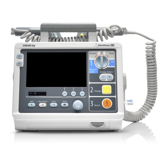
The Basics Equipment Introduction The BeneHeart D3/BeneHeart D2 Defibrillator/Monitor (hereinafter called the equipment) is a lightweight and portable defibrillator/monitor. It provides four operating modes: Monitor, Manual Defib, AED and Pacer. Monitor Mode ■ In the Monitor mode, the equipment is intended for monitoring, displaying, reviewing, storing and printing…
-
Page 22: Aed
2.2.1 The AED mode is to be used only on cardio arrest patients. The patients must be: ■ Unresponsive Not breathing or not breathing normally ■ 2.2.2 Manual Defibrillation Asynchronous defibrillation is the initial treatment for ventricular fibrillation and ventricular tachycardia in patients that are pulseless and unresponsive.
-
Page 23: Applied Parts
Applied Parts The applied parts of the equipment are: ECG electrodes and leadwires ■ ■ sensor ■ NIBP cuff sampling line/Nasal sampling cannula, airway adapter ■ ■ External defibrillation paddles Internal defibrillation paddles ■ ■ Multifunction electrode pads ■ CPR sensor Main Unit 2.4.1 Front View…
-
Page 24
Area 1 (3) (4) Alarm lamp The Alarm lamp flashes in different color and frequency to match the alarm level. Display screen AC power indicator ◆ Illuminated: the AC mains is connected. ◆ Off: the AC mains is not connected. Battery indicator ◆… -
Page 25
Area 2 Lead Select button Press this button to select the lead for the first ECG waveform. Gain select button Press this button to select the size of the first ECG waveform. Microphone It is used for voice recording in AED mode. NIBP button/Record button ◆… -
Page 26
Area 3 Mode Select knob Rotate this knob to select the operating mode or turn the equipment off. Energy Select button In the Manual Defib mode, press this button to select the energy level. Charge button Press this button to charge the defibrillator. Shock button Press this button to deliver a shock to the patient. -
Page 27: Left View
2.4.2 Left View (1) Recorder (2) ECG cable connector (3) Gas oulet (4) NIBP cuff connector (5) SpO sensor connector (6) CO sampling line connector Defibrillator/Monitor Operator’s Manual 2 — 7…
-
Page 28: Right View
2.4.3 Right View Therapy port It is used to connect the paddles cable or pads cable. 2.4.4 Rear View 2 — 8 Defibrillator/Monitor Operator’s Manual…
-
Page 29: External Paddles
Hook Battery Equipotential grounding terminal When the defibrillator/monitor and other devices are to be used together, their equipotential grounding terminals should be connected together to eliminate the potential difference between them. External power input It connects an AC power cord or a DC/AC adapter to run the equipment respectively on the external AC mains or DC power supply.
-
Page 30: Display Views
Display Views A typical screen in the Manual Defib Mode is shown below. (12) (11) (10) Patient Information area This area shows patient name, patient category, paced status, and current date and time. indicates that the patient has an implanted pacemaker. Alarm status symbols This area shows the alarm status.
-
Page 31
(11) Manual Defib information area This area shows the selected defibrillation energy, shock counter as well as prompts related to manual defibrillation. (12) Waveform area This area shows measurement waveforms. The waveform label is displayed at the upper left corner of the waveform. Defibrillator/Monitor Operator’s Manual 2 — 11… -
Page 32
This page intentionally left blank. 2 — 12 Defibrillator/Monitor Operator’s Manual… -
Page 33: Basic Operations And Settings
Basic Operations and Settings Equipment Installation WARNING • The equipment shall be installed by personnel authorized by the manufacturer. • The software copyright of the equipment is solely owned by the manufacturer. No organization or individual shall resort to juggling, copying, or exchanging it or to any other infringement on it in any form or by any means without due permission.
-
Page 34: Basic Operation
When the equipment is moved from one place to another, condensation may occur as a result of temperature or humidity difference. In this case, never start the system before the condensation disappears. NOTE • Make sure that the operating environment of the equipment meets the specific requirements. Otherwise unexpected consequences, e.g.
-
Page 35: Starting Monitoring Or Therapy
WARNING • Do not use the equipment for any monitoring or therapy procedure on a patient if you suspect it is not working properly, or if it is mechanically damaged. Contact your service personnel or Mindray. NOTE • Check that visual and auditory alarm signals are presented correctly when the equipment is powered on.
-
Page 36: Editing Current Patient Information
Rotate the Navigation knob to move the cursor on [Ok], and then press the Navigation knob to save the information inputted. ■ Changing settings Changing the ECG lead in the Monitor mode is taken as an example below: Rotate the Navigation knob to move the cursor on the ECG lead label Press the Navigation knob to highlight the selection Rotate the Navigation knob until you find the desired item, and then press the Navigation knob to confirm the selection.
-
Page 37: Changing General Settings
Changing General Settings 3.3.1 Setting the Date and Time Before putting the equipment into use for the first time, you should check and set the system date and time in accordance with your local time. To set the system time, you can choose any of the following ways: ■…
-
Page 38: Adjusting Waveform Position
■ In the AED mode Press the [High Contrast] soft key to enable the high contrast display. To disable the high contrast display, press the [Full Color] soft key. Once [High Contrast] is selected, the high contract display remains when you change the operating mode. However, the setting will not be saved if the equipment is turned off.
-
Page 39: Alarms
Alarms Alarms triggered by a vital sign that appears abnormal or by technical problems of the equipment, are indicated to you by visual and audible alarm indications. WARNING • A potential hazard exists if different alarm presets are used for the same or similar device in any single area, e.g.
-
Page 40: Alarm Indicators
Alarm Indicators When an alarm occurs, the equipment indicates it to you through visual or audible alarm indications. Alarm lamp ■ ■ Alarm tones ■ Alarm message Flashing numeric ■ NOTE • When multiple alarms of different levels occur simultaneously, the equipment will select the alarm of the highest level and give visual and audible alarm indications accordingly.
-
Page 41: Flashing Numerics
For technical alarms ■ ◆ High level alarms: ◆ Medium level alarms: yellow blue ◆ Low level alarms: 4.3.4 Flashing Numerics If an alarm triggered by an alarm limit violation occurs, the numeric of the measurement in alarm will flash every second, and corresponding alarm limit will also flash at the same frequency indicating the alarm limit is violated.
-
Page 42: Understanding The Alarm Setup Menu
WARNING • Do not rely exclusively on audible alarm system. Setting alarm volume to a low level may result in a hazard to the patient. Always keep the patient under close surveillance. Understanding the Alarm Setup Menu Press the Main Menu button on the front panel, and then select [Alarm Setup >>] to enter the [Alarm Setup] menu.
-
Page 43
Module Parameter Low alarm limit High alarm limit Auto alarm limits range Adult/pediatric Neonate Adult/pediatric Neonate (HR-30) or 90 HR×1.25 or 240 (HR + 40) or 200 Adult/pediatric: 35 to 240 HR×0.8 or 40 bpm (whichever bpm (whichever bpm whichever bpm whichever Neonate: 55 to 225 is greater) -
Page 44: Pausing Alarms
Pausing Alarms You can temporarily disable alarm indicators by pressing the Alarm Pause button on the front panel. When alarms are paused: ■ For physiological alarms, no alarm indication is shown. New physiological alarm will not be presented. The remaining alarm pause time is displayed in the physiological alarm area. ■…
-
Page 45: Latching Alarms
The parameter numeric and alarm limits still flash. ■ Technical alarms give different alarm indicators when the alarm system is reset: ■ For some technical alarms, including the NIBP-related alarms, a √ appears before the alarm message and the alarm reset symbol appears in the alarm symbol area.
-
Page 46: Actions When An Alarm Occurs
4.13 Actions When an Alarm Occurs When an alarm occurs, observe the following steps and take proper actions: Check the patient’s condition. Confirm the alarming parameter or alarm category. Identify the alarm source. Take proper action to eliminate the alarm condition. Make sure the alarm condition is corrected.
-
Page 47: Monitoring Ecg
Monitoring ECG ECG Introduction The electrocardiogram (ECG) measures the electrical activity of the heart and displays it as waveforms and numerics. The equipment enables ECG monitoring through 3-lead ECG sets, 5-lead ECG sets, external paddles and electrode pads. If both ECG sets and external paddles/electrode pads are connected, the configured ECG waveforms are displayed in the waveform area.
-
Page 48: Monitoring View
Monitoring View A typical screen in the Monitor mode is shown below. You can enter the Monitor mode by switching the Mode Select knob to Monitor. When operating in the Monitor mode, the equipment displays up to two ECG waveforms, the heart rate reading, other available parameter values and active alarm settings.
-
Page 49
5.4.2.2 ECG Electrode Placements 3-Lead Placement The following is a typical AHA electrode placement for a 3-lead ECG set: ■ RA placement: directly below the clavicle and near the right shoulder. ■ LA placement: directly below the clavicle and near the left shoulder. LL placement: on the left lower abdomen. -
Page 50: Ecg Measurement With Electrode Pads
WARNING • When using electrosurgical units (ESU), place ECG electrodes between the ESU and its grounding plate to prevent unwanted burns. Never entangle ESU cable and ECG cable together. • When using electrosurgical units (ESU), never place ECG electrodes near to the grounding plate of the ESU, as this can cause a lot of interference on the ECG signal.
-
Page 51: Ecg Measurement With External Paddles
5.4.4 ECG Measurement with External Paddles Connect the paddles cable with the equipment if not connected. Apply conductive gel to paddle electrodes. Remove the paddle set from the paddle tray by grasping the handles and pulling them straight up. Apply the external paddles to the patient by using anterior-lateral placement. ◆…
-
Page 52: Ecg Display
ECG Display The figure below shows the ECG monitoring view in 3-lead mode. It is for reference only. Your display may be configured to look slightly different. (1) ECG lead label (2) ECG waveform gain (3) ECG filter mode (4) Notch filter status (5) HR alarm limits (6) HR unit (7) PVCs values: it is shown only when arrhythmia analysis is switched on.
-
Page 53: Setting The Ecg Waveform Layout
The P-waves and T-waves should be less than 0.2mV. ■ 5.6.4 Setting the ECG Waveform Layout Select the ECG parameter area to enter the [ECG Setup] menu. Select [Cascade] and toggle between [On] and [Off]. 5.6.5 Changing ECG Waveform Size If the ECG waveform is too small or clipped, you change its size by using the Navigation knob.
-
Page 54: Adjusting The Qrs Volume
5.6.9 Adjusting the QRS Volume In the case that ECG alarm is switched on, or both ECG alarm and PR alarm are switched off, heartbeat tone is issued. To adjust the heartbeat volume: Select the ECG parameter area to enter the [ECG Setup] menu. Select [Others >>] →…
-
Page 55: Switching Arrhythmia Analysis On And Off
Arrhythmia event Description Category PVCs/min PVCs/min exceeds high limit Nonlethal arrhythmia PNP** No pace pulse detected for 1.75 x average R-to-R intervals following a QRS complex (for paced patients only). PNC** No QRS complex detected for 300 milliseconds following a pace pulse (for paced patients only).
-
Page 56: Changing Arrhythmia Threshold Settings
NOTE • The alarm level for asystole, ventricular fibrillation, ventricular tachycardia, ventricular bradycardia, extreme bradycardia, and extreme tachycardia alarms is always high and unchangeable. These alarms are always on. As long as the alarm condition occurs, corresponding alarm will be triggered whether arrhythmia analysis is switched on or off.
-
Page 57: Automatic Arrhythmia Relearn
5.7.6 Automatic Arrhythmia Relearn Arrhythmia relearning is initiated automatically whenever: ■ The ECG lead or lead label is changed The ECG lead is re-connected ■ ■ Patient category is changed The paced status is changed ■ ■ Arrhythmia analysis is switched on ■…
-
Page 58
Problem Corrective Actions Intermittent Signal 1. Check that cables are properly connected. 2. Check that electrodes are not detached or dry. Perform skin preparation again as described in 5.4 Preparing for ECG Monitoring and Measurement. 3. Check that the patient cable or leadwires are not damaged. Change them if necessary. -
Page 59: Aed
AED Introduction This chapter describes how to operate the equipment in the AED Mode. While operating in the AED Mode, the equipment analyzes the patient’s ECG waveforms and guides you through the defibrillation process. The equipment starts analyzing the patient’s heart rhythm immediately after entering the AED mode. When a shockable rhythm is detected, the equipment gives a prompt and automatically starts charging.
-
Page 60: Aed View
AED View A typical screen in the AED Mode is shown below. Operating mode AED prompt message ECG parameter and waveform area: This area displays HR numeric and one ECG waveform acquired from the electrode pads. Contact impedance indicator (configurable) It indicates the impedance between the patient and electrode pads.
-
Page 61: Shock Advised
Delivery of the shock is confirmed by the voice and screen prompt “Shock Delivered” and the shock counter on the display is updated to reflect the number of shocks given. When the configured [Shock Series] is greater than one, the equipment resumes analyzing the patient’s rhythm after the shock is delivered to see if the shock was successful.
-
Page 62: No Shock Advised (Nsa)
No Shock Advised (NSA) If a shockable rhythm is not detected, the equipment will tell you “No Shock Advised!”. If the [NSA Action] is set to [CPR] ■ The equipment enters the CPR status and you will see and hear “No Shock Advised! Paused, If Needed, Begin CPR.”…
-
Page 63: Aed Sound Recording
WARNING • The CPR metronome sounds do not indicate information regarding the patient’s condition. Because patient status can change in a short time, the patient should be assessed at all times. Do not perform CPR on a patient who is responsive or is breathing normally. NOTE •…
-
Page 64
This page intentionally left blank. 6 — 6 Defibrillator/Monitor Operator’s Manual… -
Page 65: Manual Defibrillation
Manual Defibrillation Manual Defibrillation Introduction This chapter explains how to prepare for and perform asynchronous defibrillation and synchronized cardioversion using electrode pads, external paddles and internal paddles. In the Manual Defib Mode, you must assess the ECG waveforms, decide if defibrillation or cardioversion is indicated, select appropriate energy setting, charge the equipment, and deliver the shock.
-
Page 66: Manual Defibrillation View
CAUTION • Use of Manual Defib mode may be password protected. Make sure the operator knows and remembers the password as defined in Configuration. Failure to enter correct password will prevent the delivery of manual defibrillation therapy. • Clear the conductive gel from the external paddles at the completion of the therapy to prevent the paddles from being corroded.
-
Page 67: Manual Defibrillation Procedure
Selected energy Shock counter Auxiliary parameter and/or waveform area: This area displays parameters from SpO , NIBP or CO You can define the auxiliary parameter by selecting [Manual Defib Setup] from the Configuration Main menu. Manual Defibrillation Procedure Remove clothing from the patient’s chest. Wipe moisture from the patient’s chest and, if necessary, clip or shave excessive chest hair.
-
Page 68
The current energy selection is shown in the defibrillation information area as shown below. You can also select the desired energy level by the adjusting the Energy Select buttons on the front panel or on external paddles if external paddles are used. Charge Press the Charge button on the front panel. -
Page 69: Using Pediatric Paddles
7.4.1 Using Pediatric Paddles The external paddles provide both adult paddle electrodes and pediatric paddle electrodes included inside. To use the pediatric paddles: Press the latch buttons on the external paddles. Pull forward the adult paddle electrodes to remove them. For details on the defibrillation procedures, refer to 7.4 Manual Defibrillation Procedure.
-
Page 70: Synchronized Cardioversion
Place the conductive surface of paddle electrodes against the patient’s right atrium and left ventricle, as shown in the figure below: Charge the defibrillator by pressing the Charge button on the front panel. Make sure no one is touching the patient or anything connected to the patient. Press the Shock button on the front panel.
-
Page 71: Performing Synchronized Cardioversion
CAUTION • Using internal paddles for synchronized cardioversion requires that the patient’s ECG be acquired through a standard ECG cable. The patient’s ECG acquired through the internal paddles may be unreliable for synchronized cardioversion due to excessive noise or artifact causing inappropriate R- wave detection.
-
Page 72: Remote Synchronized Cardioversion
Remote Synchronized Cardioversion The equipment can be configured to receive an ECG source from a remote patient monitor (such as a bedside patient monitor) to perform synchronized cardioversion. To do so, the remote patient monitor shall have a sync out connector and shall be connected to the multifunctional connector with a synchronous cable. To switch on remote synchronized cardioversion, set [Remote Sync] to [On] in the [Manual Defib Setup] menu through the Configuration Main menu.
-
Page 73: Contact Impedance Indicator
Contact Impedance Indicator The contact impedance indicator is used to indicate the impedance between the patient and electrode pads/ external paddles in the Manual Defib mode and AED mode, as shown below: The display of the contact impedance indicator is switched off by default. To switch it on, set [Contact Impedance Indicator] to [On] in the [Manual Defib Setup] menu through the Configuration Main menu.
-
Page 74
This page intentionally left blank. 7 — 10 Defibrillator/Monitor Operator’s Manual… -
Page 75: Cpr Feedback
Upload the latest one-hour data from the CPR sensor. For details, refer to 8.2.5 Uploading CPR Data. 8.2.1 Connecting the CPR Sensor Hold one end of the CPR sensor cable with the Mindray logo facing up, and plug it into the CPR sensor connector. Fasten the CPR sensor cable with the cable retainer.
-
Page 76: Using Cpr Filter
8.2.2 Using CPR Filter Performing CPR introduces CPR artifact into the ECG signal. You can enable the CPR filter to see a close approximation of the patient’s underlying ECG rhythm when performing CPR. To enable CPR filter: Press the Main Menu button on the front panel, and then select [Others >>] → [Configuration >>] → enter the required password.
-
Page 77: Viewing Cpr Feedback
8.2.3 Viewing CPR Feedback To view CPR feedback: Enter the CPR status by either of the following ways: ◆ In the Manual Defib mode, shake and compress the CPR sensor, or select the [CPR] softkey. ◆ In the AED mode, the system automatically enters the CPR status. From the filtered ECG displayed on the second waveform of the screen, switch the filter lead with the label “Filt..”…
-
Page 78: Uploading Cpr Data
◆ Select [Refresh] if there is power failure or CPR is interrupted within five minutes, and then select the desired CPR event. NOTE • A CPR event is automatically saved in the equipment when the interruption time exceeds five minutes. •…
-
Page 79: Noninvasive Pacing
Noninvasive Pacing Pacing Introduction In the Pacer mode, the patient’s ECG is monitored through ECG lead set and pace pulses are delivered through electrode pads. The electrode pads cannot be used to monitoring ECG rhythm and deliver pacing current at the same time.
-
Page 80: Pacing View
Pacing View A typical screen in the Pacer mode is shown below. Pacer mode Pacing prompt message ECG parameter and waveform area This area displays HR numeric and one ECG waveform acquired from the ECG Lead set, and pace pulse delivered from the electrode pads. Auxiliary parameter and/or waveform area: This area displays SpO and CO…
-
Page 81: Preparing For Pacing
Preparing for Pacing Connect the electrode pads with pads cable, and then plug the pads cable into the therapy port. Prepare the patient and apply the electrode pads to the patient. For details, refer to 5.4.1 Preparing the Patient Skin and 5.4.3 ECG Measurement with Electrode Pads. If pacing in demand mode, apply monitoring electrodes, and connect the ECG cable to the equipment.
-
Page 82: Fixed Mode Pacing
9.5.2 Fixed Mode Pacing To pace in fixed mode pacing: Switch the Mode Select knob to Pacer. Use the Navigation knob to select [Fixed Mode], then press the Navigation knob. If ECG electrodes are applied, press the Lead Select button on the front panel to select the desired lead. Use the Navigation knob to adjust the pacer rate, then press the Navigation knob in.
-
Page 83: Monitoring Resp
Monitoring Resp 10.1 Resp Introduction Impedance respiration is measured across the thorax. When the patient is breathing or ventilated, the volume of air changes in the lungs, resulting in impedance changes between the electrodes. Respiration rate (RR) is calculated from these impedance changes, and a respiration waveform appears on the equipment screen. Resp monitoring is intended for adult, pediatric and neonatal patients.
-
Page 84: Optimizing Lead Placement For Resp
NOTE • To optimize the respiration waveform, place the RA and LA electrodes horizontally when monitoring respiration with ECG Lead I; place the RA and LL electrodes diagonally when monitoring respiration with ECG Lead II. Lead I Lead II 10.4.1 Optimizing Lead Placement for Resp If you want to measure Resp and you are already measuring ECG, you may need to optimize the placement of the two electrodes between which Resp will be measured.
-
Page 85: Changing Resp Settings
10.4.2 Changing Resp Settings Select the Resp parameter area to enter the [Resp Setup] menu. Make the following settings: ◆ Select [Gain] and then choose an appropriate setting. The bigger the gain is, the larger the wave amplitude is. ◆ Select [Sweep] and then choose an appropriate setting.
-
Page 86
This page intentionally left blank. 10 — 4 Defibrillator/Monitor Operator’s Manual… -
Page 87: Monitoring Pr
Monitoring PR 11.1 PR Introduction The pulse numeric counts the arterial pulsations that result from the mechanical activity of the heart. You can display a pulse from SpO (1) PR alarm limits (2) PR unit (3) PR value NOTE • A functional tester or SpO simulator can be used to determine the pulse rate accuracy.
-
Page 88
This page intentionally left blank. 11 — 2 Defibrillator/Monitor Operator’s Manual… -
Page 89: Monitoring Spo
12.2 Identifying SpO Modules The equipment can be configured with any of the following SpO modules. Mindray SpO : the connector is blue without any no logo. ■ ■ Masimo SpO module: the connector is purple with a logo of Masimo SET.
-
Page 90: Spo2 Measurement Limitations
The SpO extension cable should be compatible with the SpO connectors. For example, you can only connect the Mindray SpO extension cable to the Mindray SpO connectors. • The SpO simulator can be used to verify the accuracy of the SpO sensor.
-
Page 91: Spo2 Display
■ Interfering substances: ◆ Intravascular dyes (such as indocyanine green, methylene blue, indigo carmine, etc.) ◆ Dyes in the measure site, such as nail polish. Environmental conditions: ■ ◆ Excessive ambient light ◆ Electrosurgery equipment. The pulse oximeter may be used during electrocautery, but this may affect the accuracy or availability of the parameters and measurements.
-
Page 92: Changing Spo
12.6 Monitoring Procedure Select an appropriate sensor according to the module type, patient category and weight. Clean the application site, e.g. removing colored nail polish from the application site. Apply the sensor to the patient. Select an appropriate extension cable according to the connector type and connect it with the equipment. Connect the sensor cable to the extension cable.
-
Page 93: Setting Spo Sensitivity (For Mindray Spo )
12.7.4 Setting SpO Sensitivity (for Mindray SpO The SpO value displayed on the screen is the average of data collected within a specific time. The shorter the averaging time is, the quicker the equipment responds to changes in the patient’s oxygen saturation level, but the measurement accuracy is relatively low.
-
Page 94: Displaying Pi (For Masimo Spo )
Signal quality indicator (SIQ) To display SpO SIQ, set [Display SIQ] to [On] from the [SpO2 Setup] menu. 12.7.9 Displaying PI (for Masimo SpO For Masimo SpO module, you can set whether to display PI in the SpO parameter area. To display PI, set [Display PI] to [On] from the [SpO2 Setup] menu.
-
Page 95: Nellcor Information
Problem Corrective Actions Do not see SpO parameter area or Check that the cable connections of SpO sensor and the extension cable waveform area on the screen are tight. Replace the SpO sensor or the extension cable if needed. Dashes “- -” display in place of numerics. 1.
-
Page 96: Masimo End-User License Agreement
Shenzhen Mindray grants to Purchaser a nonexclusive, nontransferable license, without right to sublicense, to use the copy of the incorporated software/firmware, and documentation in connection with Purchaser’s use of the Masimo Products for their labeled purpose. Shenzhen Mindray reserves all rights not expressly granted to Purchaser.
-
Page 97: Monitoring Nibp
Monitoring NIBP 13.1 NIBP Introduction Automatic non-invasive blood pressure monitoring uses the oscillometric method of measurement. It is intended for adult, pediatric and neonatal patients. To understand how this method works, we’ll compare it to the auscultative method. With auscultation, the clinician listens to the blood pressure and determines the systolic and diastolic pressures. The mean pressure can then be calculated with reference to these pressures as long as the arterial pressure curve is normal.
-
Page 98: Nibp Measurement Limitations
13.3 NIBP Measurement Limitations Measurements are impossible with heart rate extremes of less than 30 bpm or greater than 300 bpm, or if the patient is on a heart-lung machine. The measurement may be inaccurate or impossible in the following situations: If a regular arterial pressure pulse is hard to detect;…
-
Page 99: Nibp Measurement Procedure
13.6 NIBP Measurement Procedure 13.6.1 Preparing the Patient In normal use, perform NIBP measurement on a patient who is in the following position: ■ Comfortably seated Legs uncrossed ■ ■ Feet flat on the floor Back and arm supported ■ ■…
-
Page 100: Starting A Stat Measurement
WARNING • Continuous non-invasive blood pressure measurements may cause purpura, ischemia and neuropathy in the limb with the cuff. Inspect the application site regularly to ensure skin quality and inspect the extremity of the cuffed limb for normal color, warmth and sensitivity. If any abnormity occurs, move the cuff to another site or stop the blood pressure measurements immediately.
-
Page 101: Monitoring Co 2
Monitoring CO 14.1 Introduction monitoring is a continuous, non-invasive technique for determining the concentration of CO in the patient’s airway by measuring the absorption of infrared (IR) light of specific wavelengths. The CO has its own absorption characteristic and the amount of light passing the gas probe depends on the concentration of the measured CO .
-
Page 102: Co Display
14.4 Display The CO parameter and waveform areas provide FiCO measurement, EtCO measurement, awRR measurement, and a CO waveform. (1) CO waveform (2) CO alarm limits (3) End tidal CO value (EtCO ): the highest CO value measured during expiration. (4) Fraction of inspired CO (FiCO ): the lowest CO…
-
Page 103: Zeroing The Co Sensor
Connect the other end of the sampling line to the patient. ◆ For intubated patients requiring an airway adapter, install the airway adapter between the patient circuit and the ventilator Y-piece. (1) Sample line (2) Connect to the ventilator (3) Airway adapter (4) Connect to the patient ◆…
-
Page 104: Changing Co Settings
To manually start a zero calibration: Press the Main Menu button on the front panel, and then select [Others >>] → [Maintenance >>] → [Installation Mode >>] → enter the required password. Select [Maintain CO2] → [Zero]. Disconnecting the patient airway is not required when performing a zero calibration. NOTE •…
-
Page 105: Setting The Auto Standby Time
14.6.5 Setting the Auto Standby Time The equipment enters the standby mode automatically after the configured period of time if no breath is detected since the last detected breath. To set auto standby time: Select the CO parameter area to enter the [CO2 Setup] menu. Select [Others >>].
-
Page 106: Removing The Exhaust Gases From The System
To remove the sample gas to a scavenging system, connect an exhaust tube to the gas outlet connector of the module. 14.8 Calibration calibration should be performed by Mindray-qualified service personnel only once a year or when the readings go far beyond the range. For details, refer to the relevant service manual. CAUTION •…
-
Page 107: Marking Events
Marking Events During patient monitoring or therapy, some events may exert effects on the patient and as a result change related waveforms and parameter values. To help analyzing the waveforms or numerics at that time, you can mark these events. Before marking an event, you can define events A to F, for example, define event D as injecting Atropine.
-
Page 108
This page intentionally left blank. 15 — 2 Defibrillator/Monitor Operator’s Manual… -
Page 109: Freezing Waveforms
Freezing Waveforms During patient monitoring, the freeze feature allows you to freeze the currently displayed waveforms on the screen so that you can have a close examination of the patient’s status. Besides, you can select any frozen waveform for recording. Waveforms can be frozen only in the Monitor Mode. 16.1 Freezing Waveforms In the Monitor mode, press the [Freeze] soft key, then all waveforms on the screen stop refreshing or scrolling…
-
Page 110
This page intentionally left blank. 16 — 2 Defibrillator/Monitor Operator’s Manual… -
Page 111: Review
Review 17.1 Reviewing Events The equipment can automatically record and save patient events. To review events, press the Main Menu button in the Monitor mode, Manual Defib mode or Pacer mode, and then select [Review >>] → [Review Events >>]. The following figure shows the [Review Events] menu.
-
Page 112: Reviewing Cpr Events
17.3 Reviewing CPR Events If CPR is delivered by using the equipment connected with the CPR sensor, you can review CPR events on the equipment. For details, refer to 8.2.4 Reviewing CPR Events. 17 — 2 Defibrillator/Monitor Operator’s Manual…
-
Page 113: Data Management
Data Management 18.1 Data Management Overview The data management function is available in the Monitor mode, AED mode, Manual Defib mode and Pacer mode. It enables you to: Edit patient information ■ ■ Review patient events ■ Export patient data to USB memory 18.2 Generating Patient Data Archive ID is created automatically when the equipment is turned on.
-
Page 114
This page intentionally left blank. 18 — 2 Defibrillator/Monitor Operator’s Manual… -
Page 115: Recording
Recording 19.1 Using a Recorder The thermal recorder records patient information, measurement numerics and waveforms, reviewed data, auto test report, user test report and equipment configurations. Start/Stop key Press this key to start a recording or stop the current recording. Paper outlet Recorder door Indicator…
-
Page 116: Starting Recordings
◆ Event summary report ◆ Check report ◆ Configuration recording For details about alarm recording, refer to 4 Alarms. For details about task-related recordings, refer to respective sections of this manual. 19.3 Starting Recordings Recordings can be started manually or automatically. NOTE •…
-
Page 117: Setting The Recorder
19.5 Setting the Recorder 19.5.1 Selecting Waveforms for Recording Press the Main Menu button on the front panel and select [Others >>] → [Record Setup >>]. Select [Wave 1], [Wave 2] or [Wave 3], and then respectively set the desired waveforms. Selecting [Off] can switch off a waveform.
-
Page 118: Removing Paper Jam
CAUTION • Use only specified thermal paper. Otherwise, it may cause damage to the recorder’s print head, the recorder may be unable to print, or poor print quality may result. • Never pull the recorder paper with force when a recording is in process. Otherwise, it may cause damage to the recorder.
-
Page 119: Network Connection
Network Connection 20.1 Network Introduction The equipment supports the network function. The equipment can send real-time data to the CMS through wired and wireless networks or send HL7 messages. 20.2 General Network Settings 20.2.1 Selecting a Network Type Press the Main Menu button on the front panel, and select [Others >>] → [Configuration >>] → enter the required password.
-
Page 120: Connecting The Cms
20.3 Connecting the CMS The following information can be transmitted to the CMS: Patient information ■ ■ Equipment information ■ Configuration information Waveforms ■ ■ Monitoring parameters Alarms and prompt messages ■ ■ Time and date ■ Working mode Auto test report ■…
-
Page 121
◆ [Send Alarms]: if set to [On], alarms will be automatically sent to the specified HL7 server. Select [Return]. Defibrillator/Monitor Operator’s Manual 20 — 3… -
Page 122
This page intentionally left blank. 20 — 4 Defibrillator/Monitor Operator’s Manual… -
Page 123: Configuration Management
Configuration Management 21.1 Configuration Management Introduction The configuration management enables you to customize you equipment to best meet your needs. With this function, you can: View system configurations ■ ■ Change system configurations ■ Record system configurations Export configurations ■ ■…
-
Page 124: Exporting Configurations
21.4 Exporting Configurations Connect the USB flash memory to the equipment’s USB connector. Switch the Mode Select knob to Monitor, Manual Defib or Pacer. Press the Main Menu button on the front panel. Enter the Configuration Main menu by either of the following ways: ◆…
-
Page 125: Manual Defib Setup Menu
Menu Item Options/Range Default Description Language Sets the language for voice and text prompts. Date Format yyyy-mm-dd, mm-dd-yyyy, yyyy-mm-dd Sets the system date format. dd-mm-yyyy Time Format 12 h, 24 h 24 h Sets the system time format. System Time Year 2007 to 2099 2007…
-
Page 126: Aed Setup Menu
Menu Item Options/Range Default Description Charge Tone Vol High, Med, Low Sets the tone volume during the charge, and when the charge is completed. This setting is also effective in the AED mode. Contact Impedance Indicator On, Off Sets whether to display the contact impedance indicator.
-
Page 127: Pacer Setup Menu
Menu Item Options/Range Default Description Voice Volume High, Med, Low High Sets the volume level for voice prompts in the AED mode. Voice Prompt Interval Off, 30s, 60s, 90s, 120s, 150s, Sets the interval for voice 180s prompts in the AED mode. Voice Recording On, Off Sets whether to enable the…
-
Page 128
Menu Item Options/Range Default Description Lead Set 3-Lead, 5-Lead 3-Lead Sets the ECG lead type. This setting affects the default waveform position of the [Waveform Setup] menu. QRS Volume 0 to 10 This setting is linked with the [QRS Volume] setting in the [SpO2 Setup] menu ECG1 3-Lead: I, II, III… -
Page 129
Menu Item Options/Range Default Description ARR Alm Lev PVCs/min High, Med, Low R ON T VT>2 Couplet Vent Rhythm Bigeminy Trigeminy Tachy Brady Missed Beat A-Fib Multif. PVCs Nonsus. Vtac Pause Irr. Rhythm Asystole Delay 3 to 10 V-Tach Rate 100 to 200 V-Tach PVCs 3 to 99… -
Page 130: Resp Setup Menu
Mode 1 Sets the SpO tone mode Sat-Seconds 0s, 10s, 25s, 50s, 100s For Nellcor SpO module only. Sensitivity Mindray SpO High, Med, Low Different options are available to match the SpO module Masimo SpO High, Normal, APOD Normal used.
-
Page 131: Pr Setup Menu
21.6.9 PR Setup Menu Menu Item Options/Range Default Description PR Alarm On, Off PR Alm Lev High, Med, Low PR High (Low+2) to 300 Step: 1 bpm PR ranges are different for different modules. PR Low 15 to (High-2) QRS Volume 0 to 10 This setting is linked with the [QRS Volume] setting in the…
-
Page 132: Setup Menu
Menu Item Options/Range Default Description Dia High (Low+5) to 250 Step: 1 mmHg (Low+5) to 200 (Low+5) to 115 Dia Low 10 to (High-5) 21.6.11 CO Setup Menu Menu Item Options/Range Default Description Alarm On, Off Alm Lev High, Med Press.
-
Page 133: 21.6.12 Alarm Setup Menu
21.6.12 Alarm Setup Menu Menu Item Options/Range Default Description Alarm Pause Time 1, 2, 3, 5, 10, 15 min, 2 min Sets the alarm pause time. Permanent Audio Off Enabled, Disabled Disabled Sets whether the audible alarm tones are turned off. Alm Volume •…
-
Page 134: 21.6.14 Mark Event Setup Menu
21.6.14 Mark Event Setup Menu Menu Item Options/Range Default Description Event A Generic Generic Unchangeable Event B Adrenalin, Lidocaine, Adrenalin Event names that have been Atropine, Nitroglycerin, selected by previous events will Event C Lidocaine Morphine, Intubation, IV not be included in the options Access, Adenosine, of later events.
-
Page 135: 21.6.16 Data Management Setup Menu
Menu Item Options/Range Default Description Alm Rec On, Off Sets whether the parameter is automatically recorded when the related alarm is triggered. PVCs Resp SpO2 NIBP 21.6.16 Data Management Setup Menu Menu Item Options/Range Default Description Tabular Trends Interval 1 min, 2 min, 5 min, 10 min, 5 min Sets the interval that trends are 15 min, 30 min, 60 min…
-
Page 136: 21.6.19 Others Menu
Menu Item Options/Range Default Description Default Network Connection On, Off Sets whether the CMS is automatically connected after turned on. Restoring factory default configurations does not change this setting. Site Setup Select Site 1, 2 Sets the desired CMS. Restoring factory default Site Name 0 to 20 characters configurations does not change…
-
Page 137: Battery
Battery 22.1 Battery Introduction The equipment is designed to operate on battery power when external power supply is not available. The battery is charged whenever the equipment is connected to AC mains or the DC power supply through an external DC/AC adapter, regardless of whether or not the equipment is currently turned on. In case of power failure, the equipment will automatically run power from internal batteries.
-
Page 138: Installing The Battery
22.3 Installing the Battery To install the battery: Align a battery with the battery compartment. Insert the battery, and press until you hear it click into the place. To replace a battery, press the latch on the battery and push the battery to the right until you remove it. Insert a new battery into the battery compartment.
-
Page 139: Conditioning The Battery
22.5 Conditioning the Battery The performance of batteries deteriorates over time. To extend the battery service life, you are recommended to condition the batteries every three months. If the battery is not conditioned for a prolonged time, its charge indication may not be accurate and you may wrongly evaluate the remaining battery runtime.
-
Page 140: Recycling The Batteries
22.9 Recycling the Batteries A battery should be discarded if there are visual signs of damage, the battery fails, the battery aged alarm is presented, or the batteries has been used for more than two years. Properly dispose of batteries according to local regulations.
-
Page 141: Care And Cleaning
Care and Cleaning Use only the substances approved by the equipment manufacturer and methods listed in this chapter to clean or disinfect your equipment. Warranty does not cover damages caused by unapproved cleaning and disinfection substances or methods. We make no claims regarding the efficacy of the listed chemicals or methods as a means for controlling infection.
-
Page 142: Cleaning
23.2 Cleaning Your equipment should be cleaned on a regular basis. If there is heavy pollution or lots of dust and sand in your place, the equipment should be cleaned more frequently. Before cleaning the equipment, consult your hospital’s regulations for cleaning the equipment. Recommended cleaning agents are: ■…
-
Page 143: Maintenance
Maintenance 24.1 Maintenance Introduction The equipment must be maintained to be ready for immediate use. To ensure proper performance of the equipment, you should strictly perform the maintenance in this chapter. After the equipment has been used for 12 months, or whenever the equipment is repaired or upgraded, a thorough inspection should be performed to ensure the reliability.
-
Page 144: Auto Test
Maintenance Item Recommend Frequency Test Item User test Every week • Routine test: performs tests of the main control board, therapy module, monitor module, batteries, 1 J internal discharge, 50 J internal charge/external discharge • Energy delivery test: performs tests of 360 J internal charge/external discharge , optional 200 J internal discharge connected with the battery.
-
Page 145: User Test
24.3.2 User Test If the auto test fails, the user test must be performed to clear the faults. When turned on, the equipment automatically checks the time to Routine Test, Energy Delivery Test and Controls Test performed last time. The equipment can be configured to give a “User Test Due” message to remind performing the user test.
-
Page 146
24.3.2.2 Viewing the User Test Summaries The results of the user test are automatically saved as summaries. The equipment can store up to 300 historical test summaries which are listed in the sequence of time, with the latest on the top. Press the Main Menu button on the front panel, and then select [User Test >>]→… -
Page 147: Function Checks
The function checks enhance the auto test that helps the equipment to ensure the readiness. It is recommended to perform the function checks once a year. The function checks, except the recorder check, should be performed by Mindray-qualified service personnel only. 24.4.1 Recorder Check Switch the Mode Select knob to Monitor.
-
Page 148: Pacing Test
Energy Disarming Disconnect the equipment from the AC mains, and connect the equipment with fully charged battery. Switch the Mode Select knob to Manual Defib. Connect the electrode pads/external paddles to the equipment, and place the electrode pads/external paddles on the defibrillator/pacer analyzer. Set the analyzer to Energy Measurement mode, and check that the energy value is 0 or blank.
-
Page 149: Preventive Maintenance
200 mA±10mA. 24.5 Preventive Maintenance The preventive maintenance should be performed every year by Mindray-qualified service personnel only. The preventive tests includes tests performed in the installation mode, Resp test, SpO test, and electrical safety tests.
-
Page 150
This page intentionally left blank. 24 — 8 Defibrillator/Monitor Operator’s Manual… -
Page 151: Accessories
Accessories The accessory material that contacts the patients has undertaken the bio-compatibility test and is verified to be in compliance with ISO 10993-1. WARNING • WARNING Use accessories specified in this chapter. Using other accessories may cause damage to the equipment or not meet the claimed specifications.
-
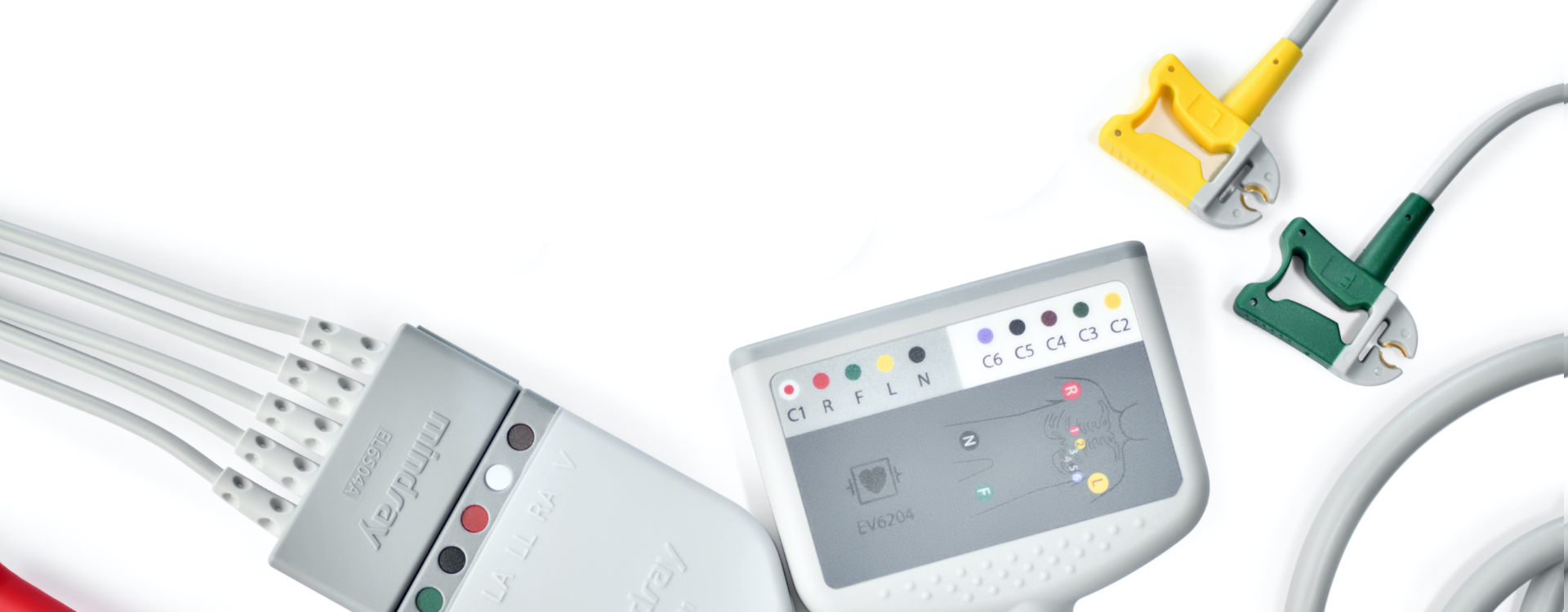
Page 152: Lead Sets
25.1.3 Lead Sets 3-Electrode Lead Sets Type Compatible with Model Applicable Remark patient Clip EL6302A Adult, pediatric 0010-30-42725 EL6304A 0010-30-42732 Long EL6306A Neonate 0010-30-42897 EL6308A Pediatric 0010-30-42899 EL6301A Adult, pediatric 0010-30-42726 EL6303A 0010-30-42731 Long EL6305A Neonate 0010-30-42896 EL6307A Pediatric 0010-30-42898 Snap EL6302B Adult, pediatric…
-
Page 153: Spo Accessories
25.2 Accessories 25.2.1 Extension Cables Module type Applicable patient Remark Mindray SpO module Adult, pediatric, neonate 0010-20-42710 Masimo SpO module 040-000332-00 8 pins, purple connector 0010-30-42738 7 pins, white connector Nellcor SpO module 0010-20-42712 25.2.2 Sensors Mindray SpO module Type…
-
Page 154: Nibp Accessories
Masimo SpO Module Type Model Applicable patient Remark Reusable FPS-1863 Adult (finger clip) 0010-10-42600 LNCS DC-I FPS-1864 Pediatric (finger clip) 0010-10-42634 LNCS-DCIP 2258 Adult, pediatric, 0010-10-43016 LNCS YI neonate Nellcor SpO Module Type Model Applicable patient Disposable MAX-A Adult (>30 kg) 0010-10-12202 MAX-P Pediatric (10 to 50 kg)
-
Page 155: Co Accessories
Type Model Applicable Applied site Limb Circumference Bladder patient (cm) Width (cm) Single CM1500A Neonate Upper arm 3.1 to 5.7 001B-30-70692 patient CM1500B 4.3 to 8 001B-30-70693 CM1500C 5.8 to 10.9 001B-30-70694 CM1500D 7.1 to 13.1 001B-30-70695 CM1501 Infant 10 to 19 001B-30-70697 CM1502 Pediatric…
-
Page 156: Therapy Accessories
Description Applicable patient Remark CapnoLine H Adult Disposable 0010-10-42575 O2Adult(008180) CapnoLine H Pediatric 0010-10-42576 O2Pediatric(008181) NIV-Line Adult(008174) Adult 0010-10-42577 NIV-LinePediatric(008175) Pediatric 0010-10-42578 25.5 Therapy Accessories Description Model Applicable patient Remark External paddles MR6601 Adult, pediatric Reusable 0651-30-77001 Multifunction MR60 Adult Disposable (5 sets/pack) 0651-30-77007 electrode pads…
-
Page 157
Description Model Conducting gel mount kit 115-007857-00 Charger Station kit (International) BatteryFeed 20 115-009187-00 Charger Station kit (US) 115-009188-00 Charger Station kit (Indian) 115-009189-00 Charger Station kit (EU) 115-009190-00 Charger Station kit (Brazilian) 115-009191-00 Charger Station kit (UK) 115-009192-00 Defibrillator/Monitor Operator’s Manual 25 — 7… -
Page 158
This page intentionally left blank. 25 — 8 Defibrillator/Monitor Operator’s Manual… -
Page 159: A Specifications
Specifications General Specifications A.1.1 Safety Specifications The equipment is classified, according to IEC 60601-1: Type of protection against electrical shock Class I, equipment energized from an external and internal electrical power source. If you suspect the integrity of the external protective earthing or the protective earthing wire, you should run the equipment on internal electrical power supply (battery).
-
Page 160: Interface Specifications
A.1.5 Interface Specifications USB connector Connects USB flash memory RJ45 connector Connects standard network cable. Multifunctional connector Connects a cable for analog output or a cable for synchronized cardioversion. A.1.6 Signal Outputs Specifications Multifunctional connector Standard Meets the requirements of EN60601-1 for short-circuit protection and leakage current ECG Analog Output (only ECG lead set) Bandwidth…
-
Page 161
Shocks: 1, 2, 3, configurable; Meeting AHA/ERC guidelines 2015 by default AED ECG analysis performance Refer to B Mindray Shockable Rhythm Analysis Algorithm. 360 J defibrillation waveform into impedance of 25Ω, 50Ω, 75Ω, 100Ω, 125Ω, 150Ω, 175Ω Time (ms) Defibrillator/Monitor Operator’s Manual… -
Page 162
Impedance 25Ω 50Ω 75Ω 100Ω 125Ω 150Ω 175Ω Accuracy Selected energy ±2J ±2J ±2J ±2J ±2J ±2J ±2J ±2J ±2J 10 J ±2J 15 J ±15% 20 J ±15% 30 J ±15% 50 J ±15% 70 J ±15% 100 J ±15% 150 J ±15%… -
Page 163: Cpr Compression Specifications
CPR Compression Specifications Compression depth Measurement range: 0.0 to 8.0 cm Effective range: 1.5 to 8.0 cm Accuracy (for effective range): ±0.5 cm or ±10%, whichever is greater Resolution: 0.1 cm Refreshing rate: ≥0.5Hz Compression rate Measurement range: 40 to 160 cpm (compressions per minute) Effective range: 40 to 160 cpm (compressions per minute) Accuracy: ±2 cpm (compression per minute) Resolution: 1 cpm…
-
Page 164
Common mode rejection Diagnostic mode: >90 dB Monitor mode: >105 dB Therapy mode: >105 dB 50/60Hz, Notch filter In Monitor and Therapy modes: notch filter turns on automatically In Diagnostic mode: notch filter is turned on manually ECG signal range ±8mV (peak-to-peak value) Calibration signal 1mV (peak-to-peak value) ±5%… -
Page 165: Ecg Specifications (From Defibrillation Electrodes)
Time to alarm for tachycardia Meets the requirements in Clause 201.7.9.2.9.101 b) 6) of IEC 60601-2-27. Waveform 4ah — range: <11 s 4a — range: <11 s 4ad — range: <11 s 4bh — range: <11 s 4b — range: <11 s 4bd — range: <11 s…
-
Page 166
Pace Pulse Pace pulse markers Pace pulses meeting the following conditions are labelled with a PACE marker: Amplitude: ±2 to ± 700 mV Width: 0.1 to 2 ms Rise time: 10 to 100 μs Pace pulse rejection When tested in accordance with the IEC 60601-2-27: 201.12.1.101.13, the heart rate meter rejects all pulses meeting the following conditions. -
Page 167: Resp Specifications
2200 to 4500Ω, using an ECG cable with 1 kΩ resistor Apnea alarm time 10 s, 15 s, 20 s, 25 s, 30 s, 35 s, 40 s A.5.4 Specifications Mindray SpO Module Standard Meet standards of ISO 80601-2-61 Measurement range…
-
Page 168: Pr Specifications
±2% (in adult/pediatric mode) 70 to 100%: ±3% (in neonate mode) 0% to 69%: Not specified Refreshing rate ≤2 s A.5.5 PR Specifications PR from Mindray SpO Module Measurement range 20 to 300 bpm Resolution 1 bpm Accuracy ±3 bpm Response time <20 s (PR value sudden changes from 25 to 240 bpm)
-
Page 169: Co Specifications
Auto mode repetition intervals 1, 2, 2.5, 3, 5, 10, 15, 20, 30, 60, 90, 120, 180, 240 or 480 min STAT mode cycle time 5 min Static pressure measurement range 0mmHg to 300mmHg Static pressure measurement accuracy ±3mmHg Maximum measurement time Adult, Pediatric: 180s Neonate:…
-
Page 170: Power Supply Specifications
Sample flowrate tolerance ±15% or ±15 ml/min, whichever is greater. Rise time Measured with a Oridion sampling line: ≤250 ms @ 50 ml/min (standard sampling line) or ≤280 ms @ 50 ml/min (extended sampling line) Response time Measured with a Oridion sampling line: ≤5 s @ 50 ml/min (standard sampling line) or ≤6.5 s @ 50 ml/min (extended sampling line) awRR measurement range 0 to 150 rpm…
-
Page 171
Battery LI24I001A charge Charged by the equipment Less than 2 hours to 90% and less than 3 hours to 100% time connected to the AC power with equipment power off; Less than 3.5 hours to 90% and less than 4.5 hours to 100% with equipment power on. -
Page 172: Recorder Specifications
Recorder Specifications Method High-resolution thermal dot array Number of waveforms 3 at maximum 6.25 mm/s, 12.5 mm/s, 25 mm/s, 50 mm/s. Error no more than ± 5% Paper speed Paper width 50 mm Grid lines The operator can choose to print grid lines or not Auto record Charge events, shock events, marked events, auto test report, parameter alarms, ARR alarms, if configured on…
-
Page 173: Wi-Fi Specifications
A.10 Wi-Fi Specifications Protocol IEEE 802.11a/b/g/n Modulation mode DSSS and OFDM Operating frequency IEEE 802.11b/g/n (at 2.4G): 2.4 GHz to 2.495 GHz IEEE 802.11a/n (at 5G): 5.15 GHz to 5.825 GHz Channel spacing IEEE 802.11b/g/n (at 2.4G): 5 MHz IEEE802.11a/n (at 5G): 20 MHz Wireless baud rate IEEE 802.11b: 1 Mbps to 11 Mbps IEEE 802.11g: 6 Mbps to 54 Mbps…
-
Page 174
• When the equipment and related products have differing environmental specifications, the effective range for the combined products is that range which is common to the specifications for all products. NOTE • The environmental specification of unspecified modules are the same as those of the main unit. Main Unit Item Temperature… -
Page 175: B Mindray Shockable Rhythm Analysis Algorithm
Database for Evaluation of Mindray Algorithm Performance The database for evaluation of Mindray algorithm performance includes international standard database and Mindray clinical database for evaluating the ECG data. The ECG data for evaluation is selected according to AHA recommendations with a 10-second wave length.
-
Page 176: Mindray Shockable Rhythm Analysis Algorithm Performance
Mindray Shockable Rhythm Analysis Algorithm Performance Test results on the performance of the equipment configured with Mindray shockable rhythm analysis algorithm meet IEC 60601-2-4 requirements and AHA recommendations Test results on IEC 60601-2-4 requirements are shown below. Rhythm category Requirement…
-
Page 177: C Emc And Radio Regulatory Compliance
EMC and Radio Regulatory Compliance The equipment meets the requirements of IEC 60601-1-2: 2014. WARNING • Use of accessories, transducers and cables other than those specified or provided by the manufacturer of this device could result in increased electromagnetic emissions or decreased electromagnetic immunity of this device and result in improper operation.
-
Page 178
If the device is operated within the electromagnetic environment listed in Table Guidance and Declaration — Electromagnetic Immunity, the equipment will remain safe and provide the following essential performance: HR accuracy, Resp accuracy, SpO accuracy, PR accuracy, NIBP accuracy, CO accuracy, Pacing rate accuracy, Pacing output accuracy, energy accuracy, CPR function, alarm, data stored, user’s interface function. -
Page 179
Guidance and Declaration — Electromagnetic Immunity The equipment is suitable for use in the electromagnetic environment specified below. The customer or the user of the equipment should assure that it is used in such an environment. Immunity test IEC 60601 Test level Compliance level Electromagnetic environment — guidance… -
Page 180: Radio Regulatory Compliance
Recommended Separation Distances between Portable and Mobile RF, Communications Equipment and This Equipment The equipment is intended for use in an electromagnetic environment in which radiated RF disturbance are controlled. The customer or the user of the equipment can help prevent electromagnetic interference by maintaining a minimum distance between portable and mobile RF communications equipment (transmitters) and the equipment as recommended below, according to the maximum output power of the communication equipment.
-
Page 181: D Defibrillator Shift Checklist
Defibrillator Shift Checklist Equipment Name: Serial Number: Department: Item Pass/ Corrective Actions/Remarks Fail Equipment Appearance ◆ Clean, no foreign substance, no crack Cables/Connectors ◆ Cables not frayed, connectors and pins not broken or loose ◆ Connectors engage securely Batteries ◆ Battery installed with at least 60% of battery capacity ◆…
-
Page 182
This page intentionally left blank. D — 2 Defibrillator/Monitor Operator’s Manual… -
Page 183: E Alarm Messages
Alarm Messages This chapter lists only the most important physiological and technical alarm messages. Some messages appearing on your equipment may not be included. In this chapter: ■ The “I” column indicates how indications of technological alarms are cleared after the Alarm Pause button or [Alarm Reset] soft key is pressed: “A”…
-
Page 184: Technical Alarm Messages
Measurement Alarm Message Cause and solution Irr. Rhythm Arrhythmia has occurred to the patient. Check the patient’s condition and the ECG connections. A-Fib The pacer appears abnormal. Check the pacer. Resp Resp Apnea The respiration signal was so weak that the equipment cannot perform respiration analysis.
-
Page 185
Measurement Alarm Message Cause and solution SpO2 SpO2 Sensor Off The SpO sensor has become detached from the patient or the module, or there is a fault with the SpO sensor, or SpO2 Sensor Fault an unspecified SpO sensor has been used. Check the sensor application site and the sensor type, and make SpO2 No Sensor sure the sensor is not damaged. -
Page 186
Measurement Alarm Message Cause and solution CO2 Sensor High Temp Check, stop using or replace the sensor. CO2 No Watertrap Check the watertrap connections. CO2 Zero Failed Check the CO connections. After the sensor’s temperature becomes stabilized, perform a zero calibration again. -
Page 187
Measurement Alarm Message Cause and solution Power board Power Board Selftest Err An error occurred to the system power supply. Restart the equipment. Power Board Volt Err Low Battery Change battery or connect the equipment to the AC power source to charge the batteries. No Battery Battery is not installed. -
Page 188
NOTE • In the “L” column “S” refers to special technological alarm. The special technological alarms cannot be paused or silenced, and the alarm volume is unchangeable. These alarms stops only when the alarm condition is eliminated. E — 6 Defibrillator/Monitor Operator’s Manual… -
Page 189: F Electrical Safety Inspection
Electrical Safety Inspection The following electrical safety tests are recommended as part of a comprehensive preventive maintenance program. They are a proven means of detecting abnormalities that, if undetected, could prove dangerous to either the patient or the operator. Additional tests may be required according to local regulations. All tests can be performed by using commercially available safety analyzer test equipment.
-
Page 190: Device Labeling
Device Labeling Check the labels provided by the manufacturer or the healthcare facilities are present and legible. Main unit label ■ ■ Integrated warning labels Protective Earth Resistance Plug the probes of the analyzer into the device’s protective earth terminal and protective earth terminal of the AC power cord.
-
Page 191: Mains On Applied Part Leakage
For BF applied parts ◆ 100μA in Normal Condition ◆ 500μA in Single Fault Condition Mains on Applied Part Leakage The Mains on Applied Part test applies a test voltage, which is 110% of the mains voltage, through a limiting resistance, to selected applied part terminals.
-
Page 192
This page intentionally left blank. F — 4 Defibrillator/Monitor Operator’s Manual… -
Page 193: G Symbols And Abbreviations
Symbols and Abbreviations Units μA microampere μV microvolt ampere ampere hour beat per minute bit per second ºC centigrade cubic centimeter centimeter decibel dyne second ºF fahrenheit gram gigahertz gutta hour hertz inch Joule kilo kilogram kilopascal litre pound meter Milliampere hour mega byte microgram…
-
Page 194: Symbols
millimeter mmHg millimeters of mercury millisecond millivolt milliwatt MΩ megaohm nanometer breaths per minute second volt volt ampere Ω watt Symbols – negative, minus percent per; divide; or plus equal to < less than > greater than ≤ less than or equal to ≥…
-
Page 195
ANSI American National Standard Institute aortic pressure arterial left foot augmented lead left arm augmented lead right arm augmented lead awRR airway respiratory rate brachial aterial pressure bispectral index blood pressure BPSK binary phase shift keying body surface area blood temperature BTPS body temperature and pressure, saturated C.I. -
Page 196
electroencephalogram electromagnetic compatibility electromyograph electromagnetic interference enflurane electrosurgical unit end-tidal EtCO end-tidal carbon dioxide end-tidal nitrous oxide ethylene oxide end-tidal oxygen femoral arterial pressure Federal Communication Commission Food and Drug Administration fraction of inspired FiCO fraction of inspired carbon oxygen fraction of inspired nitrous oxide fraction of inspired oxygen FPGA… -
Page 197
left arm left atrial pressure lateral liquid crystal display left cardiac work LCWI left cardiac work index light emitting diode left leg LVDS low voltage differential signal LVET left ventricular ejection time LVSW left ventricular stroke work LVSWI left ventricular stroke work index minimal alveolar concentration mean arterial pressure Medical Device Directive… -
Page 198
Pleth plethysmogram Pmean mean pressure pacer not captured pacer not paced Pplat plateau pressure pulse rate premature ventricular complex pulmonary vascular resistance PVRI pulmonary vascular resistance index right right arm random access memory right atrial pressure airway resistance record, recording Resp respiration reduced hemoglobin… -
Page 199
Temp temperature thoracic fluid content thoracic fluid index thin-film technology Toral oral temperature Trect rectal temperature expiratory tidal volume inspiratory tidal volume umbilical arterial pressure uninterruptible power supply universal serial bus umbilical venous pressure volts alternating current VEPT volume of electrically participating tissue velocity index work of breathing Defibrillator/Monitor Operator’s Manual… -
Page 200
This page intentionally left blank. G — 8 Defibrillator/Monitor Operator’s Manual… -
Page 201: H Device Tracking
Please fill the information in the next page, cut the table and fax it to +86 755 26582934. You can also email your information to service@mindray.com. Defibrillator/Monitor Operator’s Manual…
-
Page 202
This page intentionally left blank. H — 2 Defibrillator/Monitor Operator’s Manual… -
Page 205: I Declaration Of Conformity
Declaration of Conformity Defibrillator/Monitor Operator’s Manual I — 1…
-
Page 206
This page intentionally left blank. I — 2 Defibrillator/Monitor Operator’s Manual… -
Page 208
P/N: 046-010599-00(9.0)
- Способ управления: ручной, автоматический
- Импульс дефибрилляции: усеченный экспоненциальный бифазный
- Режим работы: асинхронная внешняя дефибрилляция
- Число разрядов: 100 (360 Дж)
- Каналы для измерения: ЭКГ
- Для взрослых, детей и новорожденных
- Регистрационное удостоверение
Арт. 6591
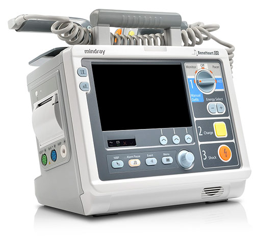
Дефибриллятор-монитор Mindray BeneHeart D3
- Описание
- Характеристики
- Комплектация
- Данные для транспортировки
- Документация
- Дефибриллятор-монитор Mindray BeneHeart D3 компактная и легкая конструкция «четыре в одном» объединяет функции мониторинга, ручной дефибрилляции, автоматической наружной дефибрилляции и кардиостимуляции
- Подходит для применения в медицинских учреждениях, а также для условий вне стационара
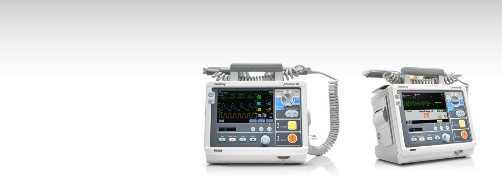
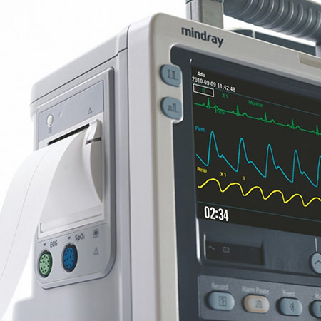
- Большой и яркий дисплей обеспечивает отображение 3 кривых и позволяет просматривать кривые ЭКГ
- Дефибрилляция, синхронизированная кардиоверсия и автоматическая наружная дефибрилляция используют бифазную технологию
- Возможность подачи разряда энергией до 360 Дж обеспечивает максимальную вероятность успешной дефибрилляции
- Мощная аккумуляторная батарея поддерживает длительный непрерывный мониторинг и подачу разрядов во время транспортировки пациента без использования внешних источников питания
Перед применением необходимо ознакомиться с инструкцией по применению (паспортом изделия) или получить консультацию специалиста
Способ управления
ручной, автоматический
Импульс дефибрилляции
усеченный экспоненциальный бифазный
Режим работы
асинхронная внешняя дефибрилляция
Уровни энергии, Дж
1–10, 15, 20, 30, 50, 70, 100, 150, 170, 200, 300, 360 — ручной режим, 100–360 — режим АНД
Число разрядов
100 (360 Дж) с интервалом в 1 мин
Разрешение, пиксели
800х480
Время от начала анализа до завершения набора энергии, не более, с
20
Электроды
взрослые/детские, многоразовые
Время заряда батареи, не более, ч
3 — при выключенном устройстве, 4,5 — при включенном
Работа от встроенной батареи, ч
2,5 — мониторинг, 100 разрядов по 360 Дж с интервалом в 1 мин — дефибрилляция
Электропитание от сети переменного тока, В/Гц
220/50
Электропитание от встроенной батареи, В
14,8
Электробезопасность
класс I, тип BF
Гарантия производителя, мес.
12
Дефибриллятор-монитор Mindray BeneHeart D3
Перед применением необходимо ознакомиться с инструкцией по применению (паспортом изделия) или получить консультацию специалиста
- Дефибриллятор-монитор — 1 шт.
- Кабель ЭКГ с электродами — 1 шт.
- Комплект электродов внешних (взрослые/детские) — 1 шт.
- Аккумулятор многоразовый — 1 шт.
- Гель 250 гр. — 1 шт.
- Рулонная бумага для термопринтера — 3 шт.
- Руководство по эксплуатации
Габариты в упаковке, м
0,550х0,410х0,375
Количество изделий в упаковке
1
Упаковка
картонная коробка
Дополнительная упаковка
требуется
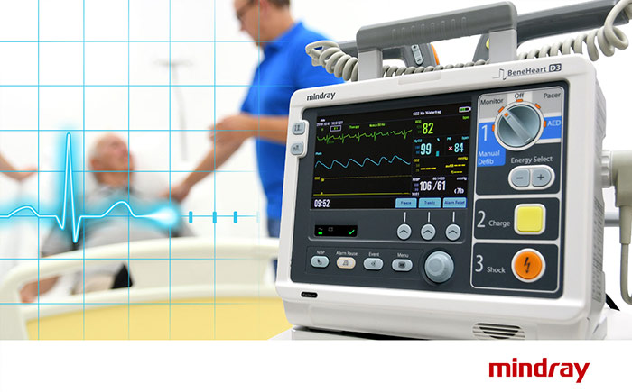
BeneHeart D3 — это компактный, надежный и легкий дефибриллятор со встроенными функциями мониторинга, ручной дефибрилляции, автоматической наружной дефибрилляции и кардиостимуляции. Этот профессиональный бифазный дефибриллятор-монитор подходит для использования в медицинских учреждениях во всем мире.
Характеристики
Быстрое проведение реанимационных мероприятий
· Включение питания за 2 секунды
· Зарядка до 200 Дж за 3 секунды
· Восстановление ЭКГ всего за 2,5 секунды
Технология 360 Дж BTe
В дефибрилляторах BeneHeart D3 используется двухфазная технология 360 Дж с автоматической компенсацией импеданса, что повышает шансы на спасение пациентов со сложными случаями дефибрилляции.
Простота в использовании
Следуя интуитивно понятным последовательным шагам (1) выбор уровня мощности; 2) заряд; 3) разряд), врач может проводить простую ручную дефибрилляцию, не отвлекаясь от пациента и не теряя драгоценное время.
Постоянная готовность в режиме ожидания
Благодаря ежедневной и еженедельной самодиагностике с автоматической загрузкой отчетов о результатах на центральную станцию дефибриллятор BeneHeart D3 может применяться для спасения жизни в любой момент. Надежный аккумулятор, выдерживающий 200 разрядов при 360 Дж и 6 часов непрерывного мониторинга, также гарантирует работоспособность устройства.
Эффективное ИТ-решение
Наше эффективное ИТ-решение позволяет управлять всей информацией с BeneHeart D3 и передавать ее в мощную систему централизованного мониторинга через WiFi 5G/2.4G. Совместимо с международным стандартным протоколом IHE HL7 и DHCP.
* Mindray предоставляет 2 варианта измерения SpO2: с помощью аппаратов Mindray, и Nellcor. Для получения информации о наличии измерителей SpO2 Masimo и Nellcor свяжитесь с местными торговыми представителями.
Комплектация
Профили конфигурации можно легко настроить и загрузить для различных клинических сценариев или эксплуатационных требований, включая значения по умолчанию, структуру экрана и конфигурацию системы.

На рынке медицинского оборудования с 2001 года
8-800-500-44-83
Адрес
105264, г. Москва, ул. 5-я Парковая, д. 46
Режим работы
Пн. – Пт.: с 9:00 до 18:00
Телефоны
Пн. – Пт.: с 9:00 до 18:00
Mindray BeneHeart D3 дефибриллятор-монитор
Запросить ТЗ
Высокое качество гарантировано!
Mindray BeneHeart D3 дефибриллятор-монитор
Запросить ТЗ
Высокое качество гарантировано!
Особенности модели
- Ручной и автоматический режим
- Функции дефибриллятора, кардиостимулятора и мониторинга
- Цветной дисплей 7”
- Объемная внутренняя память
- До 100 разрядов в 360 Дж
- Быстрый набор заряда – 200 Дж менее 5 сек
- Система голосовых и текстовых подсказок
- Защита от влаги, пыли и падений
- Аккумулятор на 2,5 ч
- Экспорт данных на ПК
Характеристики
Размеры
—
288 x 275 x 203 мм
Дисплей
—
TFT, 7”, 800 х 480
Память
—
хранение непрерывной кривой ЭКГ до 24 часов; запись речи в течение 180 мин; 1000 эпизодов для каждого пациента; профили 100 пациентов
Автономная работа
—
до 2,5 часов мониторинга
Все характеристики

Mindray BeneHeart D3 дефибриллятор-монитор
Запросить ТЗ
Высокое качество гарантировано!
- Описание
- Характеристики
- Комплектация
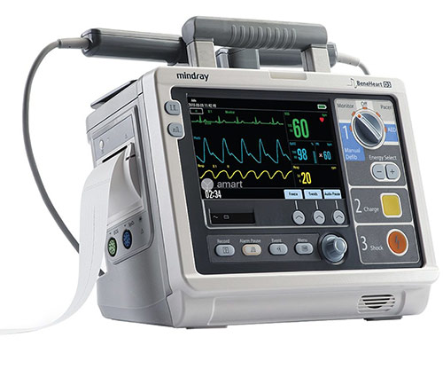
Mindray BeneHeart D3 – современный дефибриллятор-монитор, подходящий для работы как в стационаре, так и на выездах. Имеет ручной и автоматический режим, возможность измерения ЭКГ, сатурации и НИАД с выводом до 3-х кривых на дисплей 7”. Также устройство обладает функцией кардиостимуляции.
Оказание неотложной медицинской помощи облегчает продуманная система аудиовизуальных подсказок. Дефибриллятор набирает импульс в 200 Дж менее чем за 5 секунд и в 360 Дж менее чем за 8.
Автономная работа от аккумулятора рассчитана на 2,5 часа мониторинга, что позволяет оказывать помощь вне доступа к электросети. Интеллектуальная система электропитания автоматически определяет источник энергии. В сочетании с защитой от пыли и влаги аппарат подходит для работы даже в сложных условиях.
Функция записи речи до 180 минут позволяет анализировать действия специалистов. Также память BeneHeart D3 способна сохранять до 100 профилей пациента, 1000 событий и 24 часа ЭКГ. Данные электрокардиограммы удобно распечатать на встроенном термопринтере. Информацию с дефибриллятора возможно передать на ПК для просмотра, редактирования и печати.
- Основные преимущества:
- Ручной и автоматический режим;
- Функции дефибриллятора, кардиостимулятора и мониторинга;
- Возможность мониторинга ЭКГ, НИАД, SpO2;
- Объемная внутренняя память;
- Экспорт данных на ПК;
- Защита от влаги, пыли и падений;
- Автоматическое определение источника питания;
- Аккумулятор на 2,5 часа мониторинга;
- До 100 разрядов в 360 Дж;
- Быстрый набор заряда – 200 Дж менее 5 секунд;
- Цветной дисплей 7”;
- Система голосовых и текстовых подсказок;
- Взрослые электроды могут быть адаптированы в детские;
- Компактные размеры и небольшой вес;
- Заметный индикатор тревоги.
Характеристики
|
Размеры |
288 x 275 x 203 мм |
|
Вес |
4,7 кг |
|
Дисплей |
TFT, 7”, 800 х 480 |
|
Память |
хранение непрерывной кривой ЭКГ до 24 часов; запись речи в течение 180 мин; 1000 эпизодов для каждого пациента; профили 100 пациентов |
|
Страна бренда |
КНР |
|
Автономная работа |
до 2,5 часов мониторинга |
|
Электропитание от встроенной батареи |
14,8 В |
|
Электропитание от сети переменного тока |
220 В / 50 Гц |
|
Электропитание |
режим выбора источника питания производится автоматически |
|
Измерение параметров |
ЭКГ, НИАД, SpO2 |
|
Класс безопасности |
класс I, тип BF |
|
Термометрия |
встроенный терморегистратор, ширина ленты 50 мм, может использоваться для печати данных пациента и отчетов, включающих в себя 3 кривых |
|
Разряд |
100 (360 Дж), интервал 1 минута |
|
Среднее время набора энергии с новой батареей |
< 5 секунд (200 Дж), < 8 секунд (360 Дж) |
|
Программное обеспечение |
Программное обеспечение для управления данными: просмотр / редактирование / передача на ПК / печать |
|
Дополнительные функции и характеристики |
Беспроводное подключение: по протоколу 802.11 (для передачи данных), Электроды: внешние электроды, которые могут быть адаптированы как для взрослых пациентов, так и для детей |
|
Тип |
дефибриллятор |
|
Комплектация |
Дефибриллятор-монитор BeneHeart D3 с термопринтером 50 мм; Набор внешних электродов для дефибрилляции, взр/дет; Кабель ЭКГ с электродами; Литий-ионный аккумулятор, 14,8 В, 3000 мАч; Руководство пользователя на русском языке |