-
Contents
-
Table of Contents
-
Troubleshooting
-
Bookmarks
Quick Links
TRANSISTORIZED INVERTER
FR-E
500
INSTRUCTION MANUAL
HIGH PERFORMANCE
HIGH FUNCTION
FR-E520-0.1K to 7.5K-NA
FR-E540-0.4K to 7.5K-NA
FR-E510W-0.1K to 0.75K-NA
&
OUTLINE
INSTALLATION
AND WIRING
OPERATION/
CONTROL
PARAMETERS
PROTECTIVE
FUNCTIONS
SPECIFICATIONS
Chapter 1
Chapter 2
Chapter 3
Chapter 4
Chapter 5
Chapter 6
Related Manuals for Mitsubishi Electric FR-E500
Summary of Contents for Mitsubishi Electric FR-E500
-
Page 1: Instruction Manual
TRANSISTORIZED INVERTER FR-E INSTRUCTION MANUAL HIGH PERFORMANCE & HIGH FUNCTION FR-E520-0.1K to 7.5K-NA FR-E540-0.4K to 7.5K-NA OUTLINE Chapter 1 FR-E510W-0.1K to 0.75K-NA INSTALLATION Chapter 2 AND WIRING OPERATION/ Chapter 3 CONTROL Chapter 4 PARAMETERS PROTECTIVE Chapter 5 FUNCTIONS SPECIFICATIONS Chapter 6…
-
Page 2
Thank you for choosing the Mitsubishi Transistorized inverter. This instruction manual gives handling information and precautions for use of this equipment. Incorrect handling might cause an unexpected fault. Before using the inverter, please read this manual carefully to use the equipment to its optimum. Please forward this manual to the end user. -
Page 3: Safety Instructions
SAFETY INSTRUCTIONS 1. Electric Shock Prevention WARNING While power is on or when the inverter is running, do not open the front cover. You may get an electric shock. Do not run the inverter with the front cover removed. Otherwise, you may access the exposed high-voltage terminals or the charging part of the circuitry and get an electric shock.
-
Page 4
3. Injury Prevention CAUTION Apply only the voltage specified in the instruction manual to each terminal to prevent damage etc. Ensure that the cables are connected to the correct terminals. Otherwise, damage etc. may occur. Always make sure that polarity is correct to prevent damage etc. While power is on and for some time after power-off, do not touch the inverter or brake resistor as they are hot and you may get burnt. -
Page 5
( 2 ) Wiring CAUTION Do not fit capacitive equipment such as a power factor correction capacitor, radio noise filter or surge suppressor to the output of the inverter. The connection orientation of the output cables U, V, W to the motor will affect the direction of rotation of the motor. -
Page 6
CAUTION When a 400V class motor is inverter-driven, it should be insulation-enhanced or surge voltages suppressed. Surge voltages attributale to the wiring constants may occur at the motor terminals, deteriorating the insulation of the motor. When parameter clear or all clear is performed, each parameter returns to the factory setting. -
Page 7: Table Of Contents
CONTENTS 1 OUTLINE 1.1 Pre-Operation Information………………1 1.1.1 Precautions for operation………………1 1.2 Basic Configuration ………………..3 1.2.1 Basic configuration ………………..3 1.3 Structure……………………4 1.3.1 Appearance and structure ………………. 4 1.3.2 Removal and reinstallation of the front cover …………5 1.3.3 Removal and reinstallation of the wiring cover …………
-
Page 8
3 OPERATION/CONTROL 3.1 Pre-Operation Information………………49 3.1.1 Types of operation modes …………….. 49 3.1.2 Power on………………….51 3.2 About the Control Panel ………………. 52 3.2.1 Names and functions of the control panel (FR-PA02- )……..52 3.2.2 Control panel mode is changed by pressing the key …….. -
Page 9
4.2.8 Starting frequency (Pr. 13)…………….. 81 4.2.9 Load pattern selection (Pr. 14) …………….82 4.2.10 Jog operation (Pr. 15, Pr. 16) …………….83 4.2.11 Stall prevention (Pr. 22, Pr. 23, Pr. 66) …………84 4.2.12 Acceleration/deceleration pattern (Pr. 29) …………86 4.2.13 Regenerative brake duty (Pr. -
Page 10
4.2.41 User group selection (Pr. 160, Pr. 173 to Pr. 176)……… 143 4.2.42 Actual operation hour meter clear (Pr. 171)……….. 145 4.2.43 Input terminal function selection (Pr. 180 to Pr. 183)……..145 4.2.44 Output terminal function selection (Pr. 190 to Pr. 192)……..147 4.2.45 Cooling fan operation selection (Pr. -
Page 11
5.3.3 Periodic inspection………………. 175 5.3.4 Insulation resistance test using megger…………176 5.3.5 Pressure test………………..176 5.3.6 Daily and Periodic Inspection …………….177 5.3.7 Replacement of parts………………180 5.3.8 Measurement of main circuit voltages, currents and powers……185 6 SPECIFICATIONS 6.1 Standard Specifications ………………188 6.1.1 Model specifications ……………… -
Page 12
Chapter 1 1.2 Basic Configuration…………. 3 1.3 Structure …………..4 Chapter 2 <Abbreviations> y PU Control panel and parameter Chapter 3 unit (FR-PU04) y Inverter Mitsubishi transistorized inverter FR-E500 series y Pr. Chapter 4 Parameter number Chapter 5 Chapter 6… -
Page 13: Outline
1.1 Pre-Operation Information 1.1.1 Precautions for operation This manual is written for the FR-E500 series transistorized inverters. Incorrect handling may cause the inverter to operate incorrectly, causing its life to be reduced considerably, or at the worst, the inverter to be damaged. Handle the inverter properly in accordance with the information in each section as well as the precautions and instructions of this manual to use it correctly.
-
Page 14
OUTLINE ( 2 ) Preparation of instruments and parts required for operation Instruments and parts to be prepared depend on how the inverter is operated. Prepare equipment and parts as necessary. (Refer to page 49.) ( 3 ) Installation To operate the inverter with high performance for a long time, install the inverter in a proper place, in the correct direction, with proper clearances. -
Page 15: Basic Configuration
1.2 Basic Configuration OUTLINE 1.2 Basic Configuration 1.2.1 Basic configuration The following devices are required to operate the inverter. Proper peripheral devices must be selected and correct connections made to ensure proper operation. Incorrect system configuration and connections can cause the inverter to operate improperly, its life to be reduced considerably, and in the worst case, the inverter to be damaged.
-
Page 16: Structure
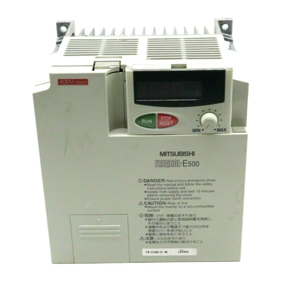
1.3 Structure OUTLINE 1.3 Structure 1.3.1 Appearance and structure (1) Front view (400V class) (100V class, 200V class) POWER lamp (yellow) Accessory cover ALARM lamp (red) Capacity plate Rating plate Front cover Wiring port cover for option (2) Without accessory cover and front cover (100V class, 200V class) (400V class) Inboard option…
-
Page 17: Removal And Reinstallation Of The
OUTLINE 1.3.2 Removal and reinstallation of the front cover z Removal (For the FR-E520-0.1K to 3.7K-NA, FR-E510W-0.1K to 0.75K-NA) The front cover is secured by catches in positions A and B as shown below. Push either A or B in the direction of arrows, and using the other end as a support, pull the front cover toward you to remove.
-
Page 18
OUTLINE (For the FR-E540-0.4K to 7.5K-NA) The front cover is fixed with catches in positions A, B and C. Push A and B in the directions of arrows at the same time and remove the cover using C as supporting points. z Reinstallation When reinstalling the front cover after wiring, fix the catches securely. -
Page 19: Removal And Reinstallation Of The Wiring Cover
OUTLINE 1.3.3 Removal and reinstallation of the wiring cover z Removal (For the FR-E520-0.1K to 7.5K-NA, FR-E510W-0.1K to 0.75K-NA) The wiring cover is fixed by catches in positions 1) and 2). Push either 1) or 2) in the direction of arrows and pull the wiring cover downward to remove.
-
Page 20: Removal And Reinstallation Of The Accessory Cover
OUTLINE 1.3.4 Removal and reinstallation of the accessory cover z Removal of the accessory cover Hold down the portion A indicated by the arrow and lift the right hand side using the portion B indicated by the arrow as a support, and pull out the accessory cover to the right.
-
Page 21: Reinstallation And Removal Of The Control Panel
OUTLINE 1.3.5 Reinstallation and removal of the control panel To ensure safety, reinstall and removal the optional control panel (FR-PA02- ) after switching power off. The charging area and control printed board are exposed on the rear surface of the control panel.
-
Page 22: Removal Of The Control Panel (Fr-Pa02- )
OUTLINE z Using the connection cable for operation 1) Fit the rear cover option FR-E5P to the back surface of the optional control panel. 2) Securely plug one end of the connection cable into the PU connector of the inverter and the other end into the adaptor of the FR-E5P option to connect it to the control panel.
-
Page 23: Exploded View
OUTLINE 1.3.7 Exploded view z FR-E520-0.1K to 7.5K-NA z FR-E510W-0.1K to 0.75K-NA Control panel (FR-PA02 Accessory cover Wiring cover Front cover z FR-E540-0.4K to 7.5K-NA Control panel (FR-PA02- Accessory Front cover cover Wiring port cover for option Wiring cover…
-
Page 24
C H A P T E R 2 CHAPTER 2 INSTALLATION AND INSTALLATIONAND WIRINNG WIRING This chapter gives information on the basic «installation and wiring» for use of this product. Always read the instructions in this chapter before using the equipment. -
Page 25: Installation And Wiring
2.1 Installation INSTALLATION AND WIRING 2 INSTALLATION AND WIRING 2.1 Installation 2.1.1 Instructions for installation For the FR-E520-0.1K to 0.75K-NA and FR-E510W-0.1K to 0.4K-NA, install the inverter with the accessory cover or control panel (FR-PA02- ) front cover open. <For the accessory cover> <For the control panel (FR-PA02 )>…
-
Page 26
10cm (3.94inch) temperatures Leave sufficient or more Cooling air clearances above Measurement and under the position inverter to ensure adequate ventilation. FR-E500 Cooling fan (1.97inch) 1cm (0.39inch) 1cm (0.39inch) (1.97inch) FR-E500 built in the or more* or more* Measurement position inverter (1.97inch) -
Page 27: Wiring
2.2 Wiring INSTALLATION AND WIRING 2.2 Wiring 2.2.1 Terminal connection diagram z 3-phase 200V power input z 3-phase 400V power input Motor 3-phase AC power supply Ground 24VDC power output and external transistor common Jumper Note 5 Remove this jumper when (+)P using the optional power-factor improving DC reactor.
-
Page 28
INSTALLATION AND WIRING z Single-phase 100V power input Motor R (L Power supply S (L Ground Note: 1. To ensure safety, connect the power input to the inverter via a magnetic contactor and earth leakage circuit breaker or no-fuse breaker, and use the magnetic contactor to switch power on-off. -
Page 29
INSTALLATION AND WIRING ( 2 ) Description of the control circuit terminals Terminal Type Symbol Description Name When the STF Forward Turn on the STF signal to start forward and STR signals rotation start rotation and turn it off to stop. are turned on simultaneously, the stop… -
Page 30
INSTALLATION AND WIRING Terminal Type Symbol Description Name Contact output indicating that the output has been stopped by the inverter protective function activated. 230VAC 0.3A, 30VDC A, B, C Alarm output 0.3A. Alarm: discontinuity across B-C (continuity across A-C), normal: continuity Output across B-C (discontinuity across A-C). -
Page 31: Wiring Of The Main Circuit
INSTALLATION AND WIRING 2.2.2 Wiring of the main circuit ( 1 ) Wiring instructions 1) It is recommended to use insulation-sleeved solderless terminals for power supply and motor wiring. 2) Power must not be applied to the output terminals (U, V, W) of the inverter. Otherwise the inverter will be damaged.
-
Page 32
INSTALLATION AND WIRING Overall wiring length (3.7K or more) 500m (1640.40 feet) maximum 300m (984.24 feet) 300m (984.24 feet) 300m (984.24 feet)+300m (984.24 feet)=600m (1968.48 feet) 6) Connect only the recommended optional brake resistor between the terminals P — PR (+ — PR). -
Page 33
INSTALLATION AND WIRING Notes on Grounding z Leakage currents flow in the inverter. To prevent an electric shock, the inverter and motor must be grounded. z Use the dedicated ground terminal to ground the inverter. (Do not use the screw in the case, chassis, etc.) For the earth connection avoid direct contact between aluminium and copper. -
Page 34
INSTALLATION AND WIRING ( 2 ) Terminal block layout FR-E520-0.1K-NA, 0.2K-NA, 0.4K-NA, FR-E520-1.5K-NA, 2.2K-NA, 3.7K-NA 0.75K-NA N/- P/+ P/+ PR Screw size (M4) Screw size (M4) Screw size (M3.5) Screw size (M4) Screw size (M3.5) FR-E520-5.5K-NA, 7.5K-NA Screw size (M5) Screw size (M5) FR-E540-0.4K to 7.5K-NA P/+ PR… -
Page 35
INSTALLATION AND WIRING ( 3 ) Cables, crimping terminals, etc. The following table lists the cables and crimping terminals used with the inputs (R (L S (L ), T (L )) and outputs (U, V, W) of the inverter and the torques for tightening the screws: 1) FR-E520-0.1K-NA to 7.5K-NA PVC insulated… -
Page 36: Wiring Of The Control Circuit
INSTALLATION AND WIRING ( 4 ) Connection of the power supply and motor z Three-phase power input Three-phase power supply 200V Three-phase power supply 400V Motor Ground Ground terminal No-fuse breaker Ground The power supply cables must be connected Connect the motor to U, V, W. In the above to R, S, T (L , L , L ).
-
Page 37
INSTALLATION AND WIRING ( 2 ) Terminal block layout In the control circuit of the inverter, the terminals are arranged as shown below: Terminal screw size: M2.5 (200V class, 100V class) Terminal layout of control circuit (400V class) *AM for the 400V class inverter. ( 3 ) Wiring method 1) For wiring the control circuit, use cables after stripping their sheaths. -
Page 38
INSTALLATION AND WIRING 1) Use tweezers etc. to remove the connector in the sink logic position and fit it in the source logic position. Do this position changing before switching power on. Note: 1. Make sure that the front cover has been installed securely. 2. -
Page 39
INSTALLATION AND WIRING • When using an external power supply for transistor output, use terminal PC as a common to prevent misoperation caused by leakage current. (Do not connect terminal SD of the inverter with terminal 0V of the external power supply. -
Page 40
INSTALLATION AND WIRING • When using an external power supply for transistor output, use terminal SD as a common to prevent misoperation caused by leakage current. Inverter AY-80 DC24V (SD) (5) How to use the STOP signal The following connection example shows how to self-hold the start signals (forward rotation, reverse rotation). -
Page 41: Connection To The Pu Connector
INSTALLATION AND WIRING 2.2.4 Connection to the PU connector ( 1 ) When connecting the control panel or parameter unit using a cable Use the option FR-CB2… or the following connector and commercially available cable: <Connection cable> y Connector : RJ45 connector Example: 5-554720-3, Nippon AMP y Cable : Cable conforming to EIA568 (e.g.
-
Page 42
Example: 5-554720-3, Nippon AMP Co., Ltd. 2. Cable : Cable conforming to EIA568 (such as 10BASE-T cable) Example: SGLPEV 0.5mm × 4P, Mitsubishi Cable Industries, Ltd. 3.*Commercially available converter examples Model: FA-T-RS40 Converter Industrial System Division Mitsubishi Electric Engineering Co., Ltd. -
Page 43
INSTALLATION AND WIRING <Wiring methods> 1) Wiring of one RS-485 computer and one inverter Computer Side Terminals Cable connection and signal direction Inverter PU connector Signal name Description 10 BASE-T Cable Receive data Receive data Send data Send data Request to send Request to send (Note 2) Clear to send… -
Page 44: Connection Of Stand-Alone Option Units
INSTALLATION AND WIRING 2.2.5 Connection of stand-alone option units The inverter accepts a variety of stand-alone option units as required. Incorrect connection will cause inverter damage or an accident. Connect and operate the option unit carefully in accordance with the corresponding option unit manual. ( 1 ) Connection of the dedicated external brake resistor (option) (Cannot be connected to 0.1K and 0.2K) Connect a brake resistor across terminals P (+) and PR.
-
Page 45
INSTALLATION AND WIRING ( 2 ) Connection of the BU brake unit (option) Connect the BU brake unit correctly Inverter Motor R (L as shown on the right. Incorrect S (L connection will damage the inverter. T (L Remove jumpers. P (+) N (-) Discharge resistor T (Note 3) -
Page 46
When connecting the high power factor converter (FR-HC) to suppress power harmonics, wire as shown below. Wrong connection will damage the high power factor converter and inverter. High power Inverter External box factor converter (FR-E500) (FR-HCB) (FR-HC) Resistor R (L Reactor 1 Reactor 2… -
Page 47: Design Information
INSTALLATION AND WIRING 2.2.6 Design information 1) Provide electrical and mechanical interlocks for MC1 and MC2 which are used for commercial power supply-inverter switch-over. When there is a commercial power supply-inverter switch-over circuit as shown below, the inverter will be damaged by leakage current from the power supply due to arcs generated at the time of switch-over or chattering caused by a sequence error.
-
Page 48: Other Wiring
2.3 Other Wiring INSTALLATION AND WIRING 2.3 Other Wiring 2.3.1 Power supply harmonics Power supply harmonics may be generated from the converter section of the inverter, affecting the power supply equipment, power capacitor, etc. Power supply harmonics are different in generation source, frequency band and transmission path from radio frequency (RF) noise and leakage currents.
-
Page 49: Japanese Harmonic Suppression Guideline
INSTALLATION AND WIRING 2.3.2 Japanese harmonic suppression guideline Harmonic currents flow from the inverter to a power receiving point via a power transformer. The harmonic suppression guideline was established to protect other consumers from these outgoing harmonic currents. 1) «Harmonic suppression guideline for household appliances and general-purpose products»…
-
Page 50
INSTALLATION AND WIRING 3) Measures against noises which are radiated by the inverter causing misoperation of peripheral devices. Inverter-generated noises are largely classified into those radiated by the cables connected to the inverter and inverter main circuit (I/O), those electromagnetically and electrostatically inducted to the signal cables of the peripheral devices close to the main circuit power supply, and those transmitted through the power supply cables. -
Page 51
INSTALLATION AND WIRING Noise Path Measures When devices which handle low-level signals and are susceptible to misoperation due to noise (such as instruments, receivers and sensors) are installed near the inverter and their signal cables are contained in the same panel as the inverter or are run near the inverter, the devices may be misoperated by air-propagated noise and the following measures must be taken: (1) Install easily affected devices as far away as possible from the… -
Page 52
INSTALLATION AND WIRING z Data line filter Noise entry can be prevented by providing a data line filter for the detector or other cable. z Data examples By using shielded cables as signal cables, By decreasing the carrier frequency, the induction noise can be reduced greatly (1/10 to noise terminal voltage* can be reduced. -
Page 53: Leakage Currents And Countermeasures
INSTALLATION AND WIRING 2.3.4 Leakage currents and countermeasures Due to the static capacitance existing in the inverter I/O wiring and motor, leakage currents flow through them. Since their values depend on the static capacitance, carrier frequency, etc., take the following measures. ( 1 ) To-ground leakage currents Leakage currents may flow not only into the inverter’s own line but also into the other lines through the ground cable, etc.
-
Page 54: Inverter-Driven 400V Class Motor
INSTALLATION AND WIRING z Countermeasures y Use the electronic overcurrent protection of the inverter. y Decrease the carrier frequency. Note that motor noise increases. Selection of Soft-PWM will make it unoffending. To ensure that the motor is protected against line-to-line leakage currents, it is recommended to use a temperature sensor to directly detect motor temperature.
-
Page 55: Peripheral Devices
INSTALLATION AND WIRING 2.3.6 Peripheral devices ( 1 ) Selection of peripheral devices Check the capacity of the motor to be used with the inverter you purchased. Appropriate peripheral devices must be selected according to the capacity. Refer to the following list and prepare appropriate peripheral devices: Power No-Fuse Breaker (NFB) or Earth Magnetic Contactor…
-
Page 56
INSTALLATION AND WIRING Note: 1. Select the type of the no-fuse breaker (NFB) in response to the power Power factor supply capacity. improving 2. The power supply cable size of the AC reactor range motor indicated assumes that its length is 20m (65.62 feet). 3. -
Page 57
INSTALLATION AND WIRING Inverter When the inverter is connected near a large- FR-BAL capacity power supply transformer (500kVA R (L or more, wiring length 10m (32.81 feet) Power S (L maximum) or there is power capacitor switch- supply T (L over, excessive peak currents may flow into P(+)P1 the power input circuit and damage the… -
Page 58
INSTALLATION AND WIRING <Example> × 5m × 70m 5.5mm 5.5mm (16.40 feet) (229.66 feet) NV Noise filter 3φ Inverter 200V 2.2kW (3HP) Ig1 Ign Note: 1. The earth leakage circuit breaker should be installed to the primary (power supply) side of the inverter. 2. -
Page 59: Instructions For Compliance With The Ul And Csa Standards
INSTALLATION AND WIRING 2.3.7 Instructions for compliance with the UL and CSA standards (Since we obtained the approval of the UL and CSA Standards from the UL, the products conforming to the Standards carry the US, Canada UL mark.) ( 1 ) Installation The above types of inverter have been approved as products for use in enclosure and approval tests were conducted under the following conditions.
-
Page 60: Instructions For Compliance With The European Standards
INSTALLATION AND WIRING 2.3.8 Instructions for compliance with the European standards (Only the 200V and 400V classes comply. The products conforming to the Low Voltage Directive carry the CE mark.) ( 1 ) EMC Directive 1) Our view of transistorized inverters for the EMC Directive A transistorized inverter does not function independently.
-
Page 61
INSTALLATION AND WIRING 3) Outline of instructions * In the 400V class inverters, the rated input voltage range is three-phase, 380V to 415V, 50Hz/60Hz. * Connect the equipment to the earth securely. Do not use an earth leakage circuit breaker as an electric shock protector without connecting the equipment to the earth. * Wire the earth terminal independently. -
Page 62: Operation/Control
CHAPTER 3 C H A P T E R 3 O P E R A T I O N OPERATION/CONTROL This chapter provides the basic «operation/control» for use of this product. Always read this chapter before using the equipment. 3.1 Pre-Operation Information ……..49 Chapter 1 3.2 About the Control Panel……….
-
Page 63: Pre-Operation Information
3.1 Pre-Operation Information 3 OPERATION/CONTROL 3.1 Pre-Operation Information 3.1.1 Types of operation modes The inverter can be operated in any of «PU operation mode», «external operation mode», «combined operation mode» and «communication operation mode». Prepare required instruments and parts according to the operation mode. For the way of changing the operation mode, refer to page 55.
-
Page 64
( 3 ) Combined operation mode 1 (Pr. 79 «operation mode selection» = 3) The start signal is an external signal. The frequency setting signal is set using the optional control panel or parameter unit. Preparation y Start signal….Switch, relay, etc. y Operation unit .. -
Page 65: Power On
3.1.2 Power on Before switching power on, check the following. z Installation check Make sure that the inverter is installed correctly in a correct place. (Refer to page 12.) z Wiring check Make sure that the main and control circuits are wired correctly. Make sure that the options and peripheral devices are selected and connected correctly.
-
Page 66: About The Control Panel
3.2 About the Control Panel 3.2 About the Control Panel With the optional control panel (FR-PA02 ), you can run the inverter, set the frequency, monitor the operation command display, set parameters, and display an error. 3.2.1 Names and functions of the control panel (FR-PA02 Cover opened Unit indication Display…
-
Page 67: Monitoring
3.2.2 Control panel mode is changed by pressing the MODE Monitoring mode Frequency setting Parameter setting mode mode (Note) MODE MODE MODE MODE MODE MODE STOP STOP STOP RESET RESET RESET Help mode Operating mode MODE MODE PU EXT MODE MODE STOP STOP…
-
Page 68: Parameter Setting Method
3.2.4 Frequency setting In the PU operation mode, set the frequency value used for operation performed under the operation command given by the key ( key). This mode is displayed only in PU operation. To frequency monitoring Frequency setting mode Set frequency changing Set frequency MODE…
-
Page 69
( 1 ) Example: To change the Pr. 79 «operation mode selection» setting from «2» (external operation mode) to «1» (PU operation mode) (For details of Pr. 79, refer to page 109.) Press the key, to choose the MODE parameter setting mode. Parameter setting mode Most significant Least significant… -
Page 70: Operation Mode
3.2.6 Operation mode The operation mode change method which is shown below is only allowed when Pr. 79 «operation mode selection» is «0». PU operation PU jog operation External operation MODE STOP RESET MODE MODE MODE To 3.2.7 Help mode Note: If the operation mode cannot be changed, refer to page 174.
-
Page 71
(1) Alarm history Four past alarms can be displayed with the key. («.» is appended to the most recent alarm.) When no alarm exists, E._ _0 is displayed. Most recent alarm When alarm occurs Frequency Current PU EXT Voltage Energization time PU EXT PU EXT (2) Alarm history clear… -
Page 72
(3) Parameter clear Initializes the parameter values to the factory settings. The calibration values are not initialized. (Parameter values are not cleared by setting «1» in Pr. 77 «parameter write disable selection») Flicker 1.5sec Cancel Note: 1. In the FR-E520-0.1K to 7.5K-NA and FR-E510W-0.1K to 0.75K-NA, Pr. 122 «communication check time interval»… -
Page 73: Operation
3.3 Operation 3.2 Operation 3.3.1 Pre-operation checks Before starting operation, check the following: z Safety Perform test operation after making sure that safety is ensured if the machine should become out of control. z Machine Make sure that the machine is free of damage. z Parameters Set the parameter values to match the operating machine (system) environment.
-
Page 74: External Operation Mode (Operation Using The External Frequency Setting Potentiometer And External Start Signal)
3.3.2 External operation mode (Operation using the external frequency setting potentiometer and external start signal) ( 1 ) Operation at 60Hz Operation command: Externally connected start signal. Frequency setting: Externally connected frequency setting potentiometer Step Description Image Power on → Operation mode check With the factory setting, the external operation mode is selected and the [EXT] indication is lit when power is switched on.
-
Page 75: Pu Operation Mode (Operation Using The Control Panel)
3.3.3 PU operation mode (Operation using the control panel) ( 1 ) Using the control panel (FR-PA02 ) for operation at 60Hz with digital frequency setting Operation command: key or key of the control panel (FR-PA02 Frequency setting: Related parameters: Pr. 79 «operation mode selection». By repeating step 2 below during motor run, speed can be varied.
-
Page 76: Combined Operation Mode 1 (Operation Using Both External Start Signal And Control Panel)
3.3.4 Combined operation mode 1 (Operation using both external start signal and control panel) When the start signal is provided externally (switch etc.) and the running frequency is set from the control panel (Pr. 79 = 3). The external frequency setting signal and PU’s forward rotation, reverse rotation and STOP keys are not accepted.
-
Page 77: Combined Operation Mode 2
3.3.5 Combined operation mode 2 When the running frequency is set from a potentiometer connected across terminals 2- 5 (frequency setting potentiometer) and the start signal is provided by the key or key of the control panel (FR-PA02 Operation command: key (or key) of the control panel (FR-PA02 Frequency setting: Externally connected frequency setting potentiometer…
-
Page 78
C H A P T E R 4 CHAPTER 4 P A R A M E T E R S PARAMETERS This chapter explains the «parameters» of this product. With the factory settings, the inverter is designed to perform simple variable-speed operation. Set necessary parameter values according to the load and operating specifications. -
Page 79: Parameters
4.1 Parameter List PARAMETERS 4 PARAMETERS 4.1 Parameter List 4.1.1 Parameter list Param- Minimum Custo- Func- Setting Factory Refer eter Name Setting tion Range Setting Number Increments Setting 6%/4% Torque boost (Note 1) 0 to 30% 0.1% (Note 11) Maximum frequency 0 to 120Hz 0.01H z (N ote 3) 120Hz Minimum frequency…
-
Page 80
PARAMETERS Param- Minimum Custo- Func- Setting Factory Refer eter Name Setting tion Range Setting Number Increments Setting Acceleration/deceleration 0, 1, 2 pattern Regenerative function 0, 1 selection 0 to 400Hz, 0.01Hz Frequency jump 1A 9999 9999 (Note 3) 0 to 400Hz, 0.01Hz Frequency jump 1B 9999… -
Page 81
PARAMETERS Param- Minimum Custo- Func- Setting Factory Refer eter Name Setting tion Range Setting Number Increments Setting Remote setting function 0, 1, 2 selection Shortest acceleration/ 0, 1, 2, deceleration mode 11, 12 0 to 500A, Reference current 0.01A 9999 9999 Reference current for 0 to 200%,… -
Page 82
PARAMETERS Param- Minimum Custo- Func- Setting Factory Refer eter Name Setting tion Range Setting Number Increments Setting Station number 0 to 31 Communication speed 48, 96, 192 0, 1 (data length Stop bit length/data length 10, 11 (data length 7) Parity check 0, 1, 2 presence/absence…
 -
Page 83
PARAMETERS Param- Minimum Custo- Func- Setting Factory Refer eter Name Setting tion Range Setting Number Increments Setting User group 1 registration 0 to 999 0 to User group 1 deletion 999,9999 User group 2 registration 0 to 999 0 to User group 2 deletion 999,9999 RL terminal function… -
Page 84
PARAMETERS Param- Minimum Custo- Func- Setting Factory Refer eter Name Setting tion Range Setting Number Increments Setting FM terminal calibration (Note 9) AM terminal calibration (Note 10) Frequency setting voltage 0 to 0 to 0.01Hz 0V 0Hz bias… -
Page 85: List Of Parameters Classified By Purpose Of Use
PARAMETERS 4.1.2 List of parameters classified by purpose of use Set the parameters according to the operating conditions. The following list indicates purpose of use and corresponding parameters. Parameter Numbers Purpose of Use Parameter numbers which must be set Operation mode selection Pr.
-
Page 86
PARAMETERS Parameter Numbers Purpose of Use Parameter numbers which must be set Frequency meter calibration Pr. 54, Pr. 55, Pr. 56, Pr. 158, Pr. 900, Pr. 901 Monitor display on control panel (FR- Pr. 54, Pr. 55, Pr. 56, Pr. 158, Pr. 900, Pr. 901 PA02- ) or parameter unit (FR-PU04) Display of speed, etc. -
Page 87: Parameters Recommended To Be Set By The User
PARAMETERS 4.1.3 Parameters recommended to be set by the user We recommend the following parameters to be set by the user. Set them according to the operation specifications, load, etc. Parameter Name Application Number Maximum frequency Used to set the maximum and minimum output frequencies.
-
Page 88: Parameter Function Details
4.2 Parameter Function Details PARAMETERS 4.2 Parameter Function Details 4.2.1 Torque boost (Pr. 0, Pr. 46) Related parameters Pr. 0 «torque boost» Pr. 3 «base frequency» Pr. 46 «second torque boost» Pr. 19 «base frequency voltage» Pr. 71 «applied motor» Pr.
-
Page 89: Output Frequency Range (Pr. 1, Pr. 2, Pr. 18)
PARAMETERS 4.2.2 Output frequency range (Pr. 1, Pr. 2, Pr. 18) Related parameters Pr. 1 «maximum frequency» Pr. 13 «starting frequency» Pr. 38 «frequency at 5V (10V) Pr. 2 «minimum frequency» input» Pr. 39 «frequency at 20m A input» Pr. 18 «high-speed maximum frequency» Pr.
-
Page 90: Base Frequency, Base Frequency Voltage (Pr. 3, Pr. 19, Pr. 47)
PARAMETERS 4.2.3 Base frequency, base frequency voltage (Pr. 3, Pr. 19, Pr. 47) Related parameters Pr. 3 «base frequency» Pr. 71 «applied motor» Pr. 80 «motor capacity» Pr. 19 «base frequency voltage» Pr. 83 «rated motor voltage» Pr. 180 to Pr. 183 (input terminal Pr.
-
Page 91: Multi-Speed Operation (Pr. 4, Pr. 5, Pr. 6, Pr. 24 To Pr. 27, Pr. 232 To Pr. 239)
PARAMETERS 4.2.4 Multi-speed operation (Pr. 4, Pr. 5, Pr. 6, Pr. 24 to Pr. 27, Pr. 232 to Pr. 239) Related parameters Pr. 4 «3-speed setting (high speed)» Pr. 1 «maximum frequency» Pr. 5 «3-speed setting (middle speed)» Pr. 2 «minimum frequency» Pr.
-
Page 92: Acceleration/Deceleration Time (Pr. 7, Pr. 8, Pr. 20, Pr. 21, Pr. 44, Pr. 45)
PARAMETERS Note: 1. The multi-speed settings override the main speeds (across terminals 2-5, 4-5). 2. The multi-speeds can also be set in the PU or external operation mode. 3. For 3-speed setting, if two or three speeds are simultaneously selected, priority is given to the frequency setting of the lower signal.
-
Page 93
PARAMETERS Pr.20 Running frequency Time Pr.7 Pr.8 Pr.44 Pr.45 Acceleration Deceleration <Setting> y Use Pr. 21 to set the acceleration/deceleration time and minimum setting increments: Set value «0» (factory setting) ..0 to 3600 seconds (m inim um setting increm ents: 0.1 second) Set value «1»……0 to 360 seconds (m inim um setting increm ents: 0.01 second) y Use Pr. -
Page 94: Electronic Overcurrent Protection (Pr. 9, Pr. 48)
PARAMETERS 4.2.6 Electronic overcurrent protection (Pr. 9, Pr. 48) Related parameter Pr. 9 «electronic overcurrent protection» Pr. 71 «applied motor» Pr. 180 to Pr. 183 Pr. 48 «second electronic overcurrent (input terminal function protection» selection) Set the current of the electronic overcurrent protection to protect the motor from overheat.
-
Page 95: Dc Dynamic Brake (Pr. 10 To Pr. 12)
PARAMETERS 4.2.7 DC dynamic brake (Pr. 10 to Pr. 12) Pr. 10 «DC injection brake operation frequency» Pr. 11 «DC injection brake operation time» Pr. 12 «DC injection brake voltage» By setting the DC injection brake voltage (torque), operation time and operation starting frequency, the stopping accuracy of positioning operation, etc.
-
Page 96: Starting Frequency (Pr. 13)
PARAMETERS 4.2.8 Starting frequency (Pr. 13) Related parameters Pr. 13 «starting frequency» Pr. 2 «minimum frequency» You can set the starting frequency between 0 and 60Hz. y Set the starting frequency at which the start signal is switched on. Parameter Factory Setting Output frequency…
-
Page 97: Load Pattern Selection (Pr. 14)
PARAMETERS 4.2.9 Load pattern selection (Pr. 14) Related parameter Pr. 14 «load pattern selection» Pr. 0 «torque boost» Pr. 46 «second torque boost» Pr. 80 «motor capacity» Pr. 180 to Pr. 183 (input terminal function selection) You can select the optimum output characteristic (V/F characteristic) for the application and load characteristics.
-
Page 98: Jog Operation (Pr. 15, Pr. 16)
PARAMETERS 4.2.10 Jog operation (Pr. 15, Pr. 16) Related parameters Pr. 15 «jog frequency» Pr. 20 «acceleration/deceleration reference frequency» Pr. 16 «jog acceleration/deceleration time» Pr. 21 «acceleration/deceleration tim e increm ents» Jog operation can be started and stopped by selecting the jog mode from the control panel and pressing and releasing the key ( key).
-
Page 99: Stall Prevention (Pr. 22, Pr. 23, Pr. 66)
PARAMETERS 4.2.11 Stall prevention (Pr. 22, Pr. 23, Pr. 66) Related parameters Pr. 22 «stall prevention operation level» Pr. 9 «electronic overcurrent protection» Pr. 48 «second electronic Pr. 23 «stall prevention operation level at overcurrent protection» double speed» Pr. 73 «0-5V/0-10V selection» Pr.
-
Page 100
PARAMETERS <Setting> y In Pr. 22, set the stall prevention operation level. Normally set it to 150% (factory setting). Set «0» in Pr. 22 to disable the stall prevention operation. y To reduce the stall prevention operation level in the high-frequency range, set the reduction starting frequency in Pr. -
Page 101: Acceleration/Deceleration Pattern (Pr. 29)
PARAMETERS 4.2.12 Acceleration/deceleration pattern (Pr. 29) Related parameters Pr. 29 «acceleration/deceleration pattern» Pr. 3 «base frequency» Pr. 7 «acceleration time» Pr. 8 «deceleration time» Pr. 20 «acceleration/deceleration reference frequency» Set the acceleration/deceleration pattern. Pr. 44 «second acceleration/deceleration time» Parameter Factory Setting Pr.
-
Page 102: Regenerative Brake Duty (Pr. 30, Pr. 70)
PARAMETERS 4.2.13 Regenerative brake duty (Pr. 30, Pr. 70) Pr. 30 «regenerative function selection» Pr. 70 «special regenerative brake duty» y When making frequent starts/stops, use the optional «brake resistor» to increase the regenerative brake duty. (more than 0.4K) Parameter Factory Setting Number…
-
Page 103: Frequency Jump (Pr. 31 To Pr. 36)
PARAMETERS 4.2.14 Frequency jump (Pr. 31 to Pr. 36) Pr. 31 «frequency jump 1A» Pr. 32 «frequency jump 1B» Pr. 33 «frequency jump 2A» Pr. 34 «frequency jump 2B» Pr. 35 «frequency jump 3A» Pr. 36 «frequency jump 3B» y When it is desired to avoid resonance attributable to the natural frequency of a mechanical system, these parameters allow resonant frequencies to be jumped.
-
Page 104: Speed Display (Pr. 37)
PARAMETERS 4.2.15 Speed display (Pr. 37) Related parameter Pr. 37 «speed display» Pr. 52 «control panel/PU main display data selection» The unit of the output frequency display of the control panel (FR-PA02- ) and PU (FR-PU04) can be changed from the frequency to the motor speed or machine speed. Parameter Factory Setting…
-
Page 105: Frequency At 5V (10V) Input (Pr. 38)
PARAMETERS 4.2.16 Frequency at 5V (10V) input (Pr. 38) Related parameters Pr. 38 «frequency at 5V (10V)» Pr. 73 «0 to 5V, 0 to 10V selection» Pr. 79 «operation m ode selection» Pr. 902 «frequency setting voltage bias» Pr. 903 «frequency setting voltage gain» y You can set the frequency Pr.38 provided when the…
-
Page 106: Up-To-Frequency Sensitivity (Pr. 41)
PARAMETERS 4.2.18 Up-to-frequency sensitivity (Pr. 41) Related parameters Pr. 41 «up-to-frequency sensitivity» Pr. 190 «RUN term inal function selection» Pr. 191 «FU term inal function selection» Pr. 192 «A, B, C output terminal function selection» The ON range of the up-to-frequency signal (SU) output when the output frequency reaches the running frequency can be adjusted between 0 and ±100% of the running frequency.
-
Page 107
PARAMETERS y You can also set the detection of the frequency used exclusively for reverse rotation. This function is effective for switching the timing of electromagnetic brake operation between forward rotation (rise) and reverse rotation (fall) during vertical lift operation etc. Parameter Factory Setting… -
Page 108: Monitor Display (Pr. 52, Pr. 54, Pr. 158)
PARAMETERS 4.2.20 Monitor display (Pr. 52, Pr. 54, Pr. 158) Related parameters Pr. 52 «control panel/PU main display Pr. 37 «speed display» data selection» Pr. 55 «frequency monitoring reference» Pr. 54 «FM terminal function selection» Pr. 56 «current monitoring reference» Pr.
-
Page 109
PARAMETERS When 100 is set in Pr. 52, the monitored values during stop and during operation differ as indicated below: Pr. 52 During During stop During operation operation/during stop Output Output frequency Set frequency Output frequency frequency Output current Output current Output voltage Output voltage Alarm display… -
Page 110: Monitoring Reference (Pr. 55, Pr. 56)
PARAMETERS 4.2.21 Monitoring reference (Pr. 55, Pr. 56) Related parameters Pr. 55 «frequency monitoring reference» Pr. 54 «FM terminal function selection» Pr. 56 «current monitoring reference» Pr. 158 «AM terminal function selection» Pr. 900 «FM terminal calibration» Set the frequency or current which is referenced Pr.
-
Page 111: Automatic Restart After Instantaneous Power Failure
PARAMETERS 4.2.22 Automatic restart after instantaneous power failure (Pr. 57, Pr. 58) Pr. 57 «coasting tim e for autom atic restart after instantaneous pow er failure» Pr. 58 «cushion tim e for autom atic restart after instantaneous pow er failure» y You can restart the inverter without stopping the motor (with the motor coasting) when power is restored after an instantaneous power failure.
-
Page 112: Remote Setting Function Selection (Pr. 59)
PARAMETERS 4.2.23 Remote setting function selection (Pr. 59) Related parameters Pr. 59 «remote setting function selection» Pr. 1 «maximum frequency» Pr. 7 «acceleration time» Pr. 8 «deceleration time» If the operator panel is located away from the Pr. 18 «high-speed maximum control box, you can use contact signals to frequency»…
-
Page 113: Shortest Acceleration/Deceleration Mode (Pr. 60 To Pr. 63)
PARAMETERS CAUTION W hen selecting this function, re-set the m axim um frequency according to the m achine. 4.2.24 Shortest acceleration/deceleration mode (Pr. 60 to Pr. 63) Pr. 60 «shortest acceleration/deceleration mode» Related parameters Pr. 7 «acceleration time» Pr. 61 «reference current» Pr.
-
Page 114
PARAMETERS <Setting> • Set the parameters when it is desired to improve the performance in the shortest acceleration/deceleration mode. ( 1 ) Pr. 61 «reference current setting» Setting Reference Current 9999 (factory setting) Referenced from rated inverter current 0 to 500A Referenced from setting (rated motor current) ( 2 ) Pr. -
Page 115: Retry Function (Pr. 65, Pr. 67 To Pr. 69)
PARAMETERS 4.2.25 Retry function (Pr. 65, Pr. 67 to Pr. 69) Pr. 65 «retry selection» Pr. 67 «number of retries at alarm occurrence» Pr. 68 «retry waiting time» Pr. 69 «retry count display erasure» When any protective function (major fault) is activated and the inverter stops its output, the inverter itself resets automatically and performs retries.
-
Page 116
PARAMETERS Use Pr. 67 to set the number of retries at alarm occurrence. Pr. 67 Setting Number of Retries Alarm Signal Output Retry is not made. 1 to 10 1 to 10 times Not output. 101 to 110 1 to 10 times Output. -
Page 117: Applied Motor (Pr. 71)
PARAMETERS 4.2.26 Applied motor (Pr. 71) Related parameters Pr. 71 «applied motor» Pr. 0 «torque boost» Pr. 12 «DC dynamic brake voltage» Pr. 19 «base frequency voltage» Pr. 80 «motor capacity» Pr. 96 «auto tuning setting/status» Set the motor used. y When using the Mitsubishi constant-torque motor, set «1»…
-
Page 118: Pwm Carrier Frequency (Pr. 72, Pr. 240)
PARAMETERS 4.2.27 PWM carrier frequency (Pr. 72, Pr. 240) Pr. 72 «PWM frequency selection» Pr. 240 «Soft-PWM setting» You can change the motor tone. y By parameter setting, you can select Soft-PWM control which changes the motor tone. y Soft-PWM control changes motor noise from a metallic tone into an unoffending complex tone.
-
Page 119: Voltage Input (Pr. 73)
PARAMETERS 4.2.28 Voltage input (Pr. 73) Related parameters Pr. 73 «0-5V/0-10V selection» Pr. 22 «stall prevention operation level» Pr. 38 «frequency at 5V (10V) input» y You can change the input (terminal 2) specifications in response to the frequency setting voltage signal. When entering 0 to 10VDC, always make this setting. Parameter Factory Setting…
-
Page 120: Input Filter Time Constant (Pr. 74)
PARAMETERS 4.2.29 Input filter time constant (Pr. 74) Pr. 74 «filter time constant» You can set the input section’s internal filter constant for an external voltage or current frequency setting signal. y Effective for eliminating noise in the frequency setting circuit. y Increase the filter time constant if steady operation cannot be performed due to noise.
-
Page 121
PARAMETERS <Setting> Pr. 75 PU Disconnection PU Stop Reset Selection Setting Detection Selection Reset input normally enabled. If the PU is disconnected, Pressing the Reset input enabled only when the operation will be continued. STOP RESET protective function is activated. decelerates the Reset input normally enabled. -
Page 122: Parameter Write Inhibit Selection (Pr. 77)
PARAMETERS Note: 1. By entering the reset signal (RES) during operation, the inverter shuts off output while it is reset, the data of the electronic overcurrent protection and regenerative brake duty are reset, and the motor coasts. 2. The PU disconnection detection function judges that the PU is disconnected when it is removed from the inverter for more than 1 second.
-
Page 123: Reverse Rotation Prevention Selection (Pr. 78)
PARAMETERS Note: 1. The parameters half-tone screened in the parameter list can be set at any time. 2. If Pr. 77 = «2», the values of Pr. 23, Pr. 66, Pr. 71, Pr. 79, Pr. 90, Pr. 96, Pr. 180 to Pr. 183 and Pr. 190 to Pr. 192 cannot be written during operation. Stop operation when changing their parameter settings.
-
Page 124: Operation Mode Selection (Pr. 79)
PARAMETERS 4.2.33 Operation mode selection (Pr. 79) Related parameters Pr. 79 «operation mode selection» Pr. 4 to Pr. 6, Pr. 24 to Pr. 27, Pr. 232 to Pr. 239 Used to select the operation mode of the inverter. «m ulti-speed operation» The inverter can be run from the control panel or Pr.
-
Page 125
PARAMETERS Note: Either «3» or «4» may be set to select the PU/external combined operation. These settings differ in starting method. ( 1 ) Switch-over mode During operation, you can change the current operation mode to another operation mode. Operation Mode Switching Control/Operating Status Switching External operation to PU… -
Page 126
PARAMETERS 2) Function MRS Signal Function/Operation Output stopped during external operation. Operation mode can be switched to PU operation mode. Parameter values can be rewritten in PU operation mode. PU operation allowed. Forcibly switched to external operation mode. External operation allowed. Switching to PU operation mode inhibited. -
Page 127: General-Purpose Magnetic Flux Vector Control Selection (Pr. 80)
PARAMETERS ( 3 ) Operation mode switching by external signal 1) Preparation Set «8» (switching to other than external operation mode) in Pr. 79. Use any of Pr. 180 to Pr. 183 (input terminal function selection) to set the terminal used for X16 signal input.
-
Page 128
PARAMETERS <Operating conditions> y The motor capacity is equal to or one rank lower than the inverter capacity. y The number of motor poles is any of 2, 4, and 6. (4 poles only for the constant- torque motor) y Single-motor operation (one motor for one inverter) is performed. y The wiring length between the inverter and motor is within 30m (98.42 feet). -
Page 129: Offline Auto Tuning Function (Pr. 82 To Pr. 84, Pr. 90, Pr. 96)
PARAMETERS 4.2.35 Offline auto tuning function (Pr. 82 to Pr. 84, Pr. 90, Pr. 96) Related parameters Pr. 82 «motor exciting current» Pr. 7 «acceleration time» Pr. 9 «electronic overcurrent Pr. 83 «rated motor voltage» protection» Pr. 71 «applied motor» Pr.
-
Page 130
PARAMETERS <Operating conditions> y The motor is connected. y The motor capacity is equal to or one rank lower than the inverter capacity. y Special motors such as high-slip motors and high-speed motors cannot be tuned. y The motor may move slightly. Therefore, fix the motor securely with a mechanical brake, or before tuning, make sure that there will be no problem in safety if the motor runs. -
Page 131
PARAMETERS „ Parameter details Parameter Setting Description Number 0 to 500A Set the rated motor current (A). 0, 100 Thermal characteristics suitable for standard motor Thermal characteristics suitable for Mitsubishi’s constant- 1, 101 torque motor 3, 103 Standard motor 13, 113 Constant-torque motor Select «offline auto tuning setting»… -
Page 132
PARAMETERS ( 3 ) Monitoring the offline tuning status When the parameter unit (FR-PU04) is used, the Pr. 96 value is displayed during tuning on the main monitor as shown below. When the control panel is used, the same value as on the PU is only displayed: y Control panel display (FR-PA02 (For inverter trip) 2. -
Page 133
PARAMETERS 4) Error display definitions Error Display Error Cause Remedy Inverter trip Make setting again. Increase Current limit (stall prevention) function was acceleration/deceleration time. activated. Set «1» in Pr. 156. Converter output voltage reached 75% of Check for fluctuation of power rated value. -
Page 134
PARAMETERS <Setting the motor constant as desired> z To set the motor constant without using the offline auto tuning data <Operating procedure> 1. Set «801» in Pr. 77. Only when the Pr. 80 setting is other than «9999», the parameter value of the motor constant (Pr. 90) can be displayed. Though the parameter values of other than the motor constant (Pr. -
Page 135: Computer Link Operation (Pr. 117 To Pr. 124)
PARAMETERS 4.2.36 Computer link operation (Pr. 117 to Pr. 124) Pr. 117 «station number» Pr. 118 «communication speed» Pr. 119 «stop bit length/data length» Pr. 120 «parity check presence/absence» Pr. 121 «number of communication retries» Pr. 122 «communication check time interval» Pr.
-
Page 136
PARAMETERS <Setting> Parameter Name Setting Description Number Station number specified for communication from the Station PU connector. 0 to 31 number Set the inverter station numbers when two or more inverters are connected to one personal computer. 4800 baud Communica- 9600 baud tion speed 19200 baud… -
Page 137
PARAMETERS *1. If a data error is detected and a retry must be made, execute retry operation with the user program. The inverter comes to an alarm stop if the number of consecutive retries exceeds the parameter setting. *2. On receipt of a data error occurrence, the inverter returns «reply data 3» to the computer again. -
Page 138
PARAMETERS Note: 1. The inverter station numbers may be set between H00 and H1F (stations 0 and 31) in hexadecimal. 2. *3 indicates the control code. 3. *4 indicates the CR or LF code. When data is transmitted from the computer to the inverter, codes CR (carriage return) and LF (line feed) are automatically set at the end of a data group on some computers. -
Page 139
PARAMETERS 2) Inverter station number Specify the station number of the inverter which communicates with the computer. 3) Instruction code Specify the processing request, e.g. operation, monitoring, given by the computer to the inverter. Hence, the inverter can be run and monitored in various ways by specifying the instruction code as appropriate. -
Page 140
PARAMETERS 7) Error code If any error is found in the data received by the inverter, its definition is sent back to the computer together with the NAK code. (Refer to page 129.) Note: 1. When the data from the computer has an error, the inverter will not accept that data. -
Page 141: Setting Items And Set Data
PARAMETERS <Setting items and set data> After completion of parameter settings, set the instruction codes and data then start communication from the computer to allow various types of operation control and monitoring. Number Instruction Item Description of Data Code Digits H0001: External operation Read Operation…
-
Page 142
PARAMETERS Number Instruction Item Description of Data Code Digits b0: Inverter running (RUN) b1: Forward rotation 0 0 0 0 0 0 b2: Reverse rotation (For example 1) Inverter status b3: Up to frequency (SU) 2 digits [Example 1] H02 … During forward b4: Overload (OL) monitor rotation… -
Page 143
PARAMETERS Number Instruction Item Description of Data Code Digits H00 to H6C and H80 to HEC parameter values are changed. Read H00: Pr. 0 to Pr. 96 values are accessible. Link H01: Pr. 117 to Pr. 158 and Pr. 900 to Pr. 905 parameter values are accessible. -
Page 144
PARAMETERS <Error Code List> The corresponding error code in the following list is displayed if an error is detected in any communication request data from the computer: Error Item Definition Inverter Operation Code number errors consecutively Computer NAK detected in communication request data error from the computer is greater than allowed number of retries. -
Page 145
PARAMETERS ( 5 ) Communication specifications for RS-485 communication Operation Mode Operation Communication Item Location Operation from PU External Operation Connector Run command (start) Enable Disable Enable Running frequency setting Enable (Combined operation mode) Computer user Monitoring Enable Enable program via Parameter write Enable (*3) Disable (*3) -
Page 146: Pid Control (Pr. 128 To Pr. 134)
PARAMETERS 4.2.37 PID control (Pr. 128 to Pr. 134) Related parameters Pr. 128 «PID action selection» Pr. 73 «0-5V/0-10V selection» Pr. 79 «operation mode selection» Pr. 129 «PID proportional band» Pr. 180 to Pr. 183 (input terminal function selection) Pr. 130 «PID integral time» Pr.
-
Page 147
PARAMETERS ( 2 ) PID action overview 1) PI action A combination of proportional control action (P) and integral control action (I) for providing a manipulated variable in response to deviation and changes with time. [Operation example for stepped changes of process value] Note: PI action is the sum of P and I Deviation Set point… -
Page 148
PARAMETERS 4) Reverse action Increases the manipulated variable (output frequency) if deviation X (set point — process value) is positive, and decreases the manipulated variable if deviation is negative. Deviation Process value [Heating] Cold → fi up X>0 Set point X <0 Hot →… -
Page 149
PARAMETERS ( 3 ) Wiring example y Pr. 190 = 14 y Pr. 191 = 15 y Pr. 192 = 16 Inverter Pump Motor R (L Power supply S (L T (L Forward rotation Reverse rotation For 2-wire For 3-wire type type (Note 2) -
Page 150
PARAMETERS ( 4 ) I/O signals Signal Terminal Used Function Description Set point input Enter the set point for PID control. Enter the 4 to 20mADC process value signal Process value input from the detector. Output to indicate that the process value Upper limit output signal exceeded the upper limit value. -
Page 151
PARAMETERS ( 5 ) Parameter setting Parameter Setting Name Description Number No PID action action For heating, pressure control, etc. PID reverse action selection For cooling, etc. PID forward action If the proportional band is narrow (parameter setting is small), the manipulated variable varies greatly with a slight change of the process value. -
Page 152
PARAMETERS ( 7 ) Calibration example (A detector of 4mA at 0°C (32°F) and 20mA at 50°C (122°F) is used to adjust the room temperature to 25°C (77°F) under PID control. The set point is given to across inverter terminals 2-5 (0-5V).) START Determine the set point. -
Page 153
PARAMETERS <Set point input calibration> 1. Apply the input voltage of 0% set point setting (e.g. 0V) to across terminals 2-5. 2. Make calibration using Pr. 902. At this time, enter the frequency which should be output by the inverter at the deviation of 0% (e.g. 0Hz). 3. -
Page 154: Output Current Detection Function (Pr. 150, Pr.151)
PARAMETERS 4.2.38 Output current detection function (Pr. 150, Pr.151) Related parameters Pr. 150 «output current detection level» Pr. 190 to Pr. 192 (output terminal function Pr. 151 «output current detection time» selection) y If the output current remains higher than the Pr. 150 setting during inverter operation for longer than the time set in Pr.
-
Page 155: Zero Current Detection (Pr. 152, Pr.153)
PARAMETERS 4.2.39 Zero current detection (Pr. 152, Pr.153) Related parameters Pr. 152 «zero current detection level» Pr. 190 to Pr. 192 (output terminal function selection) Pr. 153 «zero current detection time» When the inverter’s output current falls to «0», torque will not be generated. This may cause a gravity drop when the inverter is used in vertical lift application.
-
Page 156: Stall Prevention Function And Current Limit Function (Pr. 156)
PARAMETERS CAUTION The zero current detection level setting should not be too high, and the zero current detection time setting should not be too long. Otherwise, the detection signal may not be output when torque is not generated at a low output current.
-
Page 157
PARAMETERS <Setting> Refer to the following tables and set the parameter as required. Stall Prevention Stall Prevention Signal Signal Operation Voltage Operation Voltage Output Output : Activated : Activated : Not activated : Not activated Fast-Response Fast-Response Operation Operation Pr. 156 Current Limit Pr. -
Page 158: User Group Selection (Pr. 160, Pr. 173 To Pr. 176)
PARAMETERS 4.2.41 User group selection (Pr. 160, Pr. 173 to Pr. 176) Pr. 160 «user group read selection» Pr. 173 «user group 1 registration» Pr. 174 «user group 1 deletion» Pr. 175 «user group 2 registration» Pr. 176 «user group 2 deletion» Among all parameters, a total of 32 parameters can be registered to two different user groups.
-
Page 159
PARAMETERS ( 3 ) Set the required value in Pr. 160 to make the user group or groups valid or invalid. Pr. 160 Setting Description Previous parameters read User group 1’s parameters read User group 2’s parameters read User group 1 and 2 parameters read Note: 1. -
Page 160: Actual Operation Hour Meter Clear (Pr. 171)
PARAMETERS 4.2.42 Actual operation hour meter clear (Pr. 171) Pr. 171 «actual operation hour meter Related parameter clear» Pr. 52 «Control panel/PU main display data selection» You can clear the actual operation hour of the monitoring function. Parameter Factory Setting Number Setting Range…
-
Page 161
PARAMETERS <Setting> Refer to the following list and set the parameters. Signal Related Setting Function Name Parameters Pr. 4 to Pr. 6 Pr. 59 = 0 Low-speed operation command Pr. 24 to Pr. 27 Pr. 232 to Pr. 239 Pr. 59 = 1, 2 * Remote setting (setting clear) Pr. -
Page 162: Output Terminal Function Selection (Pr. 190 To Pr. 192)
PARAMETERS 4.2.44 Output terminal function selection (Pr. 190 to Pr. 192) Pr. 190 «RUN terminal function selection» Pr. 191 «FU terminal function selection» Pr. 192 «ABC terminal function selection» You can change the functions of the open collector and contact output terminals. Parameter Terminal Factory…
-
Page 163: Cooling Fan Operation Selection (Pr. 244)
PARAMETERS Pr. 232 to Pr. 239 Î Refer to Pr. 4. Pr. 240 Î Refer to Pr. 72. 4.2.45 Cooling fan operation selection (Pr. 244) Pr. 244 «cooling fan operation selection» You can control the operation of the cooling fan built in the inverter (whether there is a cooling fan or not depends on the models.
-
Page 164: Slip Compensation (Pr. 245 To Pr. 247)
PARAMETERS 4.2.46 Slip compensation (Pr. 245 to Pr. 247) Pr. 245 «rated slip» Pr. 246 «slip compensation time constant» Pr. 247 «constant-output region slip compensation selection» The inverter output current may be used to assume motor slip to keep the motor speed constant.
-
Page 165: Ground Fault Detection At Start (Pr. 249)
PARAMETERS 4.2.47 Ground fault detection at start (Pr. 249) (400V class does not have this function) Pr. 249 «ground fault detection at start» You can select whether ground fault detection at start is made or not. Ground fault detection is made only immediately after the start signal is input to the inverter. If a ground fault occurs during operation, the protective function is not activated.
-
Page 166: Stop Selection (Pr. 250)
PARAMETERS 4.2.48 Stop selection (Pr. 250) Related parameters Pr. 250 «stop selection» Pr. 7 «acceleration time» Pr. 8 «deceleration time» Pr. 44 «second acceleration/ deceleration time» Pr. 45 «second deceleration time» Used to select the stopping method (deceleration to a stop or coasting) when the start signal (STF/STR) switches off.
-
Page 167
PARAMETERS When the Pr. 250 value is 8888, the functions of terminals STF and STR change as shown below: STF = start signal, STR = rotation direction signal Inverter Operating Status Stop Forward rotation Reverse rotation When the Pr. 250 value is any of 1000 to 1100 seconds, the functions of terminals STF and STR are the same as when the Pr. -
Page 168: Meter (Frequency Meter) Calibration (Pr. 900) (200V Class, 100V Class)
PARAMETERS 4.2.49 Meter (frequency meter) calibration (Pr. 900) (200V class, 100V class) Related parameters Pr. 900 «FM terminal calibration» Pr. 54 «FM terminal function selection» Pr. 55 «frequency monitoring reference» Pr. 56 «current monitoring reference» z By using the control panel or parameter unit, you can calibrate a meter connected to terminal FM to full scale deflection.
-
Page 169
PARAMETERS <Operation procedure> y When using the control panel (FR-PA02- 1) Select the PU operation mode. 2) Set the running frequency. 3) Press the key. 4) Read Pr. 900 «FM terminal calibration». 5) Press the key to run the inverter. (Motor need not be connected.) 6) Hold down the key to adjust the meter pointer to a required position. -
Page 170: Meter (Frequency Meter) Calibration (Pr. 901) (400V Class)
PARAMETERS 4.2.50 Meter (frequency meter) calibration (Pr. 901) (400V class) Related parameters Pr. 901 «AM terminal calibration» Pr. 55 «frequency monitoring reference» Pr. 56 «current monitoring reference» Pr. 158 «AM terminal function selection» z By using the control panel or parameter unit, you can calibrate a meter connected to terminal AM to full scale deflection.
-
Page 171
PARAMETERS <Operation procedure> y When using the control panel (FR-PA02- 1) Select the PU operation mode. 2) Set the running frequency. 3) Press the key. 4) Read Pr. 901 «AM terminal calibration». 5) Press the key to run the inverter. (Motor need not be connected.) 6) Hold down the key to adjust the meter pointer to a required position. -
Page 172: Biases And Gains Of The Frequency Setting Voltage (Current)
PARAMETERS 4.2.51 Biases and gains of the frequency setting voltage (current) (Pr. 902 to Pr. 905) Related parameters Pr. 902 «frequency setting voltage bias» Pr. 38 «frequency at 5V (10V) input» Pr. 903 «frequency setting voltage gain» Pr. 39 «frequency at 20mA input»…
-
Page 173: Adjustment Procedure
PARAMETERS Pr. 903 «frequency setting voltage gain» (Pr.902, Pr. 904, Pr. 905 can also be adjusted similarly.) <Adjustment procedure> When using an external frequency setting signal to set the frequency. (1)Power-on (monitoring mode) Hz RUN MODE STOP RESET (2)Choose the PU operation mode. 1) Using the key, make sure that the PU operation mode has been selected.
-
Page 174
PARAMETERS 2) Set «1» (PU operation mode) in Pr. 79 «operation mode selection». Example:To change the external operation mode (Pr. 79=2) to the PU operation mode (Pr. 79=1) Using the key, MODE choose the «parameter setting mode» as in 1). Parameter setting mode Most significant Least significant… -
Page 175
PARAMETERS (3)Read Pr. 903 and show the current setting of the gain frequency. (Pr. 902, Pr. 904 and Pr. 905 can also be adjusted similarly.) Parameter setting mode Using the key, choose the «parameter setting mode» as in (2)-1). MODE MODE STOP RESET… -
Page 176
PARAMETERS 1) When not adjusting the gain voltage → go to (5) 2) When adjusting any point by applying a voltage → go to (6) 3) When adjusting any point without applying a voltage → go to (7) (5)How to adjust the gain frequency only without the voltage being adjusted Monitoring the analog Press the key once to display… -
Page 177
PARAMETERS (8)Press the key to shift to the next parameter. (9)Re-set Pr. 79 «operation mode» according to the operation mode to be used. Note: 1. If the Pr. 903 or Pr. 905 (gain adjustment) value is changed, the Pr. 20 value does not change. -
Page 178
C H A P T E R 5 CHAPTER 5 PROTECTIVE PROTECTIVE FUNCTIONS FUNCTIONS This chapter explains the «protective functions» of this product. Always read the instructions before using the equipment. 5.1 Errors (Alarms) …………163 5.2 Troubleshooting …………172 Chapter 1 5.3 Precautions for Maintenance and Inspection .. -
Page 179: Protective Functions
5.1 Errors (Alarms) PROTECTIVE FUNCTIONS 5 PROTECTIVE FUNCTIONS 5.1 Errors (Alarms) If any fault has occurred in the inverter, the corresponding protective function is activated to bring the inverter to an alarm stop and automatically give the corresponding error (alarm) indication on the optional control panel or the panel display.
-
Page 180
PROTECTIVE FUNCTIONS Operation Panel Indication E. OC3 FR-PU04 OC During Dec Overcurrent shut-off during deceleration Name When the inverter output current reaches or exceeds approximately 200% of the rated current during deceleration Description (other than acceleration or constant speed), the protective circuit is activated to stop the inverter output. -
Page 181
PROTECTIVE FUNCTIONS Operation Panel Indication FR-PU04 E. OV3 OV During Dec Regenerative overvoltage shut-off during deceleration or stop Name If regenerative energy causes the inverter’s internal main circuit DC voltage to reach or exceed the specified value, the Description protective circuit is activated to stop the inverter output. It may also be activated by a surge voltage generated in the power supply system. -
Page 182
PROTECTIVE FUNCTIONS Operation Panel Indication E. FIN FR-PU04 H/Sink O/Temp Fin overheat Name If the cooling fin overheats, the overheat sensor is actuated Description to stop the inverter output. • Check for too high ambient temperature. Check point • Check for cooling fin clogging. Corrective action Set the ambient temperature to within the specifications. -
Page 183
PROTECTIVE FUNCTIONS Operation Panel Indication FR-PU04 E. OLT Stll Prev STP Stall prevention Name The running frequency has fallen to 0 by stall prevention Description activated. (OL while stall prevention is being activated.) Check point Check the motor for use under overload. Corrective action Reduce the load weight. -
Page 184
PROTECTIVE FUNCTIONS Operation Panel Indication E. RET FR-PU04 Retry No Over Retry count exceeded Name If operation cannot be resumed properly within the number of Description retries set, this function stops the inverter output. Check point Find the cause of alarm occurrence. Eliminate the cause of the error preceding this error Corrective action indication. -
Page 185
PROTECTIVE FUNCTIONS (3) Warnings Operation Panel Indication FR-PU04 OL (Stll Prev STP) Name Stall prevention (overcurrent) During If a current of more than 150% (Note 4) of acceleration the rated inverter current flows in the motor, this function stops the increase in frequency until overload… -
Page 186
PROTECTIVE FUNCTIONS Operation Panel Indication FR-PU04 PU stop Name STOP A stop made by pressing the key of the PU has been RESET Description set in Pr. 75 «PU stop selection». STOP Check for a stop made by pressing the key of the RESET Check point… -
Page 187: To Know The Operating Status At The Occurrence Of Alarm
PROTECTIVE FUNCTIONS 5.1.2 To know the operating status at the occurrence of alarm When any alarm has occurred, the display automatically switches to the indication of the corresponding protective function (error). By pressing the key at this point MODE without resetting the inverter, the display shows the output frequency. In this way, it is possible to know the running frequency at the occurrence of the alarm.
-
Page 188: Troubleshooting
5.2 Troubleshooting PROTECTIVE FUNCTIONS 5.2 Troubleshooting POINT: Check the corresponding areas. If the cause is still unknown, it is recommended to initialize the parameters (return to factory settings), re-set the required parameter values, and check again. 5.2.1 Motor remains stopped 1) Check the main circuit y Check that a proper power supply voltage is applied (control panel display is provided).
-
Page 189: Speed Greatly Differs From The Setting
PROTECTIVE FUNCTIONS 5.2.3 Speed greatly differs from the setting y Check that the frequency setting signal is correct. (Measure the input signal level.) y Check that the following parameter settings are correct (Pr. 1, Pr. 2, Pr. 38, Pr. 39, Pr. 245, Pr. 902 to Pr. 905, Pr. 19). y Check that the input signal lines are not affected by external noise.
-
Page 190: Operation Mode Is Not Changed Properly
PROTECTIVE FUNCTIONS 5.2.8 Operation mode is not changed properly If the operation mode does not change correctly, check the following: 1. External input signal …Check that the STF or STR signal is off. When it is on, the operation mode cannot be changed. 2.
-
Page 191: Precautions For Maintenance And Inspection
5.3 Precautions for Maintenance and Inspection PROTECTIVE FUNCTIONS 5.3 Precautions for Maintenance and Inspection The transistorized inverter is a static unit mainly consisting of semiconductor devices. Daily inspection must be performed to prevent any fault from occurring due to adverse influence by the operating environment, such as temperature, humidity, dust, dirt and vibration, changes in the parts with time, service life, and other factors.
-
Page 192: Insulation Resistance Test Using Megger
PROTECTIVE FUNCTIONS 5.3.4 Insulation resistance test using megger 1) Before performing the insulation resistance test using a megger on the external circuit, disconnect the cables from all terminals of the inverter so that the test voltage is not applied to the inverter. 2) For the continuity test of the control circuit, use a meter (high resistance range) and do not use the megger or buzzer.
-
Page 193: Daily And Periodic Inspection
PROTECTIVE FUNCTIONS 5.3.6 Daily and Periodic Inspection Interval Periodic* Inspection Description Method Criterion Instrum ent Item Ambient temperature: -10°C to +50°C Check ambient (14°F to 122°F), Therm om eter, Surrounding temperature, humidity, Refer to page 12. non-freezing. hygrom eter, environment Ambient recorder dust, dirt, etc.
-
Page 194
PROTECTIVE FUNCTIONS Interval Periodic* Inspection Description Method Criterion Instrum ent Item (1) Check for chatter (1) Auditory check. (1) No fault. during operation. (2) Check for rough (2) Visual check. (2) No fault. Relay surface on contacts. (1) Check balance of (1) Measure voltage (1) Phase-to- output voltages… -
Page 195
PROTECTIVE FUNCTIONS z Checking the inverter and converter modules <Preparation> (1)Disconnect the external power supply cables (R, S, T (L )) and motor cables (U, V, W). (2)Prepare a meter. (Use 100Ω range.) <Checking method> Change the polarity of the meter alternately at the inverter terminals R (L ), S (L T (L ), U, V, W, P (+) and N (−), and check for continuity. -
Page 196: Replacement Of Parts
PROTECTIVE FUNCTIONS 5.3.7 Replacement of parts The inverter consists of many electronic parts such as semiconductor devices. The following parts may deteriorate with age because of their structural or physical characteristics, leading to reduced performance or failure of the inverter. For preventive maintenance, the parts must be changed periodically.
-
Page 197
PROTECTIVE FUNCTIONS (For the FR-E540-1.5K to 7.5K-NA) 1) Remove the front cover (Refer to page 5.). 2) Unplug the fan connector. The cooling fan is connected to the cooling fan connector beside the main circuit terminal block of the inverter. Unplug the connector. -
Page 198
PROTECTIVE FUNCTIONS z Reinstallation (For the FR-E520-0.75K to 7.5K-NA) 1) After confirming the orientation of the fan, reinstall the fan to the cover so that the arrow on the left of «AIR FLOW» faces in AIR FLOW the opposite direction of the fan cover. Note: If the air flow is set in the wrong direction, the inverter life can be shorter. -
Page 199
PROTECTIVE FUNCTIONS (For the FR-E540-1.5K to 7.5K-NA) 1) After confirming the orientation of the fan, reinstall the fan to the ↑AIR FLOW cover so that the arrow on the left of «AIR FLOW» faces in the opposite direction of the fan cover. Note: If the air flow is set in the wrong direction, the inverter life can be shorter. -
Page 200
PROTECTIVE FUNCTIONS ( 2 ) Smoothing capacitors A large-capacity aluminum electrolytic capacitor is used for smoothing the DC in the main circuit, and an aluminum electrolytic capacitor is also used for stabilizing the control power in the control circuit. Their characteristics are adversely affected by ripple current, etc. When the inverter is operated in an ordinary, air-conditioned environment, change the capacitors about every 5 years. -
Page 201: Measurement Of Main Circuit Voltages, Currents And Powers
PROTECTIVE FUNCTIONS 5.3.8 Measurement of main circuit voltages, currents and powers z Measurement of voltages and currents Since the voltages and currents on the inverter power supply and output sides include harmonics, accurate measurement depends on the instruments used and circuits measured.
-
Page 202
PROTECTIVE FUNCTIONS Measuring Points and Instruments Measuring Remarks Item Measuring Point Instrument (Reference Measured Value) Power supply Is the commercial power supply Across R-S (L ), S-T (L Moving-iron type AC voltage within permissible variation of AC ) and T-R (L voltmeter (V1) voltage (refer to page 188). -
Page 203
PROTECTIVE FUNCTIONS Note: 1. Use FFT to measure the output voltage accurately. It can not be measured accurately with a meter or general instrumentation. 2. When the carrier frequency exceeds 5kHz, do not use the instrument because overcurrent losses occurring in the metallic parts inside the instrument will increase and may lead to burnout. -
Page 204
C H A P T E R 6 CHAPTER 6 S P E C I F I C A T I O N S SPECIFICATIONS This chapter provides the «specifications» of this product. Always read the instructions before using the equipment 6.1 Standard Specifications ………. -
Page 205: Specifications
6.1 Standard Specifications SPECIFICATIONS 6 SPECIFICATIONS 6.1 Standard Specifications 6.1.1 Model specifications (1) 3-phase 200V power supply Type FR-E520- 0.1K 0.2K 0.4K 0.75K 1.5K 2.2K 3.7K 5.5K 7.5K 0.75 Applicable motor capacity (Note 1) Rated capacity (kVA) (Note 2) 12.6 17.5 Rated current (A) (Note 6)
-
Page 206
SPECIFICATIONS (2) 3-phase 400V power supply Type FR-E540- 0.4K 0.75K 1.5K 2.2K 3.7K 5.5K 7.5K 0.75 Applicable motor capacity (Note 1) Rated capacity (kVA) (Note 2) 13.0 Rated current (A) (Note 6) (1.4) (2.2) (3.8) (5.4) (8.7) 150% 60 seconds 200% 0.5 seconds Overload capacity (Note 3) (inverse-time characteristics) -
Page 207
SPECIFICATIONS (3) Single-phase 100V power supply Type FR-E510W- K-NA 0.1K 0.2K 0.4K 0.75K 0.75 Applicable motor capacity (Note 1) Rated capacity (kVA) (Note 2) Rated output current (A) (Note 7) (0.8) (1.4) (2.5) (4.1) 150% 60 seconds 200% 0.5 seconds (inverse-time Overload capacity (Note 3) characteristics) -
Page 208: Common Specifications
SPECIFICATIONS 6.1.2 Common specifications Soft-PWM control/high carrier frequency PWM control can be selected. Control system V/F control or general-purpose magnetic flux vector control can be selected. Output frequency range 0.2 to 400Hz (starting frequency variable between 0 and 60Hz) Across terminals 2-5: 1/500 of maximum set frequency (5VDC input), Analog input Frequency 1/1000 (10VDC, 4-20mADC input)
-
Page 209
SPECIFICATIONS Maximum/minimum frequency setting, frequency jump operation, external thermal relay input selection, automatic restart operation after Operation functions instantaneous power failure, forward/reverse rotation prevention, slip compensation, operation mode selection, offline auto tuning function, PID control, computer link operation (RS-485) 2 open collector output signals can be selected from inverter running, up to frequency, frequency detection, overload alarm, zero current Operating status detection, output current detection, PID upper limit, PID lower limit, PID… -
Page 210: Outline Drawings
SPECIFICATIONS 6.1.3 Outline drawings (1) 200V class, 100V class z FR-E520-0.1K-NA, 0.2K-NA, 0.4K-NA, 0.75K-NA z FR-E510W-0.1K-NA, 0.2K-NA, 0.4K-NA φ5 hole 5 (0.20) 4 (0.16) 55 (2.17) 6 (0.24) 56 (2.20) 6 (0.24) (0.43) 68 (2.68) Capacity FR-E520-0.1K-NA 76 (2.99) 10 (0.39) 55 (2.17) FR-E520-0.2K-NA 76 (2.99)
-
Page 211
SPECIFICATIONS z FR-E520-1.5K-NA, 2.2K-NA z FR-E510W-0.75K-NA 2-φ5 hole 8 (0.31) 5 (0.20) 29 (1.14) 11 (0.43) 68 (2.68) (0.43) 6 (0.24) 6 (0.24) 96 (3.78) 108 (4.25) Wiring holes Inverter Model FR-E520-1.5K-NA, 131 (5.16) 65 (2.56) 55 (2.17) 2.2K-NA Cooling FR-E510W-0.75K-NA 155 (6.10) 59 (2.32) 85 (3.35) -
Page 212
SPECIFICATIONS z FR-E520-3.7K-NA 2-φ5 hole 5 (0.20) 5 (0.20) 82.5 19.5 (0.77) (3.25) 68 (2.68) 11 (0.43) 55 (2.17) 72 (2.83) 55.5 (2.19) 114.5 (4.51) 138 (5.43) 158 (6.22) 6 (0.24) 6 (0.24) 170 (6.69) Wiring holes Cooling fan×2 (Unit: mm (inches)) -
Page 213
SPECIFICATIONS z FR-E520-5.5K-NA, 7.5K-NA 2-φ6 hole 6 (0.24) 96 (3.78) 68 (2.68) (0.63) 11 (0.43) 57.5 10 (0.39) (2.26) 8 (0.31) 164 (6.46) 8 (0.31) 112.5 (4.43) 180 (7.09) 170 (6.69) Wiring holes Cooling fan (Unit: mm (inches)) -
Page 214
SPECIFICATIONS (2) 400V class z FR-E540-0.4K, 0.75K, 1.5K, 2.2K, 3.7K-NA 2-φ5 hole 11 (0.43) 61 (2.40) 5 (0.20) 6 (0.24) 128 (5.04) 6 (0.24) 140 (5.51) Inverter Type FR-E540-0.4K, 116 (4.57) 44 (1.73) 0.75K-NA FR-E540-1.5K 136 (5.35) 64 (2.52) to 3.7K-NA Note: There is no cooling fan in the Cooling fan ×… -
Page 215
SPECIFICATIONS z FR-E540-5.5K, 7.5K-NA 2-φ5 hole 64 (2.52) 73 (2.87) (0.43) (0.20) 148 (5.83) 208 (8.19) 6 (0.24) (0.24) 220 (8.66) Cooling fan × 2 (Unit: mm (inches)) -
Page 216: Appendix
APPENDIX A P P E N D I X This chapter provides «supplementary information» for use of this product. Always read the instructions before using the equipment. Appendix 1 Data Code List ……… 199 APPENDIX…
-
Page 217: Appendix 1 Data Code List
APPENDIX 1 Data Code List APPENDIX Appendix 1 Data Code List Link Parameter Extension Data Code Func- Parameter Name Setting tion Number Read Write (Data Code 7F/FF) Torque boost Maximum frequency Minimum frequency Base frequency Multi-speed setting (high speed) Multi-speed setting (middle speed) Multi-speed setting (low speed) Acceleration time Deceleration time…
-
Page 218
Link Parameter Extension Data Code Func- Parameter Name Setting tion Number Read Write (Data Code 7F/FF) Up-to-frequency sensitivity Output frequency detection Output frequency detection for reverse rotation Second acceleration/deceleration time Second deceleration time Second torque boost Second V/F (base frequency) Second electronic overcurrent protection Control panel/PU main display… -
Page 219
Link Parameter Extension Data Code Func- Parameter Name Setting tion Number Read Write (Data Code 7F/FF) Motor capacity Motor exciting current Rated motor voltage Rated motor frequency Motor constant (R1) Auto-tuning setting/status Station number Communication speed Stop bit length/data length Parity check presence/absence Number of communication retries Communication check time… -
Page 220
Link Parameter Extension Data Code Func- Parameter Name Setting tion Number Read Write (Data Code 7F/FF) RL terminal function selection RM terminal function selection RH terminal function selection MRS terminal function selection RUN terminal function selection FU terminal function selection A, B, C terminal function selection Multi-speed setting (speed Multi-speed setting (speed 9) -
Page 221
REVISIONS *The manual number is given on the bottom left of the back cover. Print Date *Manual Number Revision Jul., 1998 IB(NA)-66866-A First edition Additions Mar., 1999 IB(NA)-66866-B • Three-phase 400V power input specifications May., 1999 IB(NA)-66866-C Additions • Single-phase 100V power input specifications…
 Stop bit length/data length 10, 11 (data length 7) Parity check 0, 1, 2 presence/absence…
 |
|
|||||||||||||
| pea.ru » Частотные преобразователи купить в Москве по самым низким ценам » Преобразователи частоты Mitsubishi Electric » Mitsubishi FR-E500, FR-E540 Преобразователи частоты купить по лучшей цене
Оригинальный частотный преобразователь Mitsubishi FR-E 500 имеет прекрасные технические характеристиками, которые позволяют ему занимать лидирующие позиции на современном рынке аналогичного оборудования. Данная модель частотника Mitsubishi подключается к однофазной и трехфазной системе сетей с выходной мощностью, которая составляет от 0,4 до 2,2 кВт для одной фазы и от 0,4 до 7,5 кВт для трехфазной сети. Такие технические показатели модели характеризуются:
Особенности частотных преобразователей Mitsubishi Electric FR-E 500Основными преимуществами оригинальных частотных преобразователей Mitsubishi Electric являются:
Наиболее широко частотный преобразователь Mitsubishi FR-E 500, цена которого является минимальной на сегодняшний день в нашей компании, используется для подключения разнообразных прядильных машин, специальных вязальных аппаратов, ткацкого оборудования, транспортеров, насосов, различных вентиляторов, специальных приводов ворот и дверей и другого оборудования. Основные технические характеристики
Масса и габариты
Дополнительная информация, консультации, ценыМы предложим эффективное и экономичное решение. Воспользуйтесь опытом наших технических специалистов — заполните форму справа, или позвоните. Частотно-регулируемые привода, устройства плавного пуска Mitsubishi Electric, Control Techniques и другие.
|
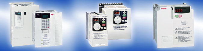
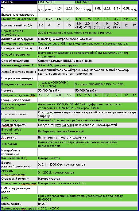
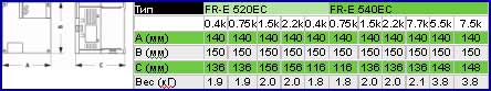
-
Mitsubishi FR — S500 — page 1
FR — S 500 T RANS I S T O RI Z E D I NV E RT E R IN S T R U C T IO N M A N U A L (D e ta i l e d ) Ch a p t e r 3 Ch a p t e r 2 Ch a p t e r 4 F UNCT I O NS Ch a p t e r 1 W I RI NG F UNCT I O NS SPEC I F I C AT I O N S PR O T EC TI VE HE A D O F F I CE: M I T SUB I S HI D ENK I B L DG M A RUNO UCHI T O K Y O 1 0 0 — 8 3 1 0 P r i nt ed i n J apan …
-
Mitsubishi FR — S500 — page 2
A-1 Thank you for choosing this Mitsubishi Transistorized inverter. This instruction manual (detailed) provides instructions for advanced use of the FR-S500 series inverters. Incorrect handling might cause an unexpected fault. Before using the inverter, always read this instruction manual and the instruction manual (basic) [IB-0600026] packed with …
-
Mitsubishi FR — S500 — page 3
A-2 2. Fire Prevention CA UTION Mount the inverter to incombustible material. M ounting it to or near co mbustible material can cause a fire. If the inverter has become faulty, switch off the inverter power. A continuous flow of large current could cause a fire. Do not connect a resis tor directly to the DC terminals P( + ), N( − ). This could ca …
-
Mitsubishi FR — S500 — page 4
A-3 (2) W iring CA UTION Do not fit capacitive equipment such as power factor correction capacitor, radio noise filter or surge suppressor to the output of the inverter. The connection orientation of the output cable s U, V, W to the m otor will affect the direction of rotation of the motor. (3) Trial run CA UTION Check all parameters, and ensur e …
-
Mitsubishi FR — S500 — page 5
A-4 (6) Maintenance, inspection and parts replacement CA UTION Do not carry out a megger (insulation resist ance) test on the c ontrol circuit of the inverter. (7) Disposing of the inverter CA UTION Treat as industrial waste. (8) General i nstructions Many of the diagrams and drawings in this instruction manual show the inverter without a cover, or …
-
Mitsubishi FR — S500 — page 6
I CONTENTS 1. WIRING 1 1.1 Japanese Version …………………………………………………………………………. 2 1.1.1 Term inal c onn ection diagram ………………………………………………………….. 2 1.1.2 Layou t and wir ing of m ain circu it term inals ……………………………………….. 3 1.2 N …
-
Mitsubishi FR — S500 — page 7
II 1.8.3 Curr ent i nput s elec tion «AU si gnal «: Set ting «4» ……………………………….. 38 1.8.4 Start self -hol ding s electi on (ST OP s ignal) : S etting «5»……………………… 38 1.8.5 Out put sh ut-of f (MR S signa l): Sett ing «6» ………………………………………… …
-
Mitsubishi FR — S500 — page 8
III 2.6.2 Set ting dial function selectio n ………………………………………………… 83 2.6. 3 Mo nitor ing r efere nce …………………………………………………….. 84 2.7 Restart Opera tion Param eters ……………………………………………………… 84 2.7. 1 Res tart s etti ng ………………. …
-
Mitsubishi FR — S500 — page 9
IV 3. PROTECTIVE FUNCTIONS 136 3.1 Errors (Alarms) ………………………………………………………………………….137 3.1.1 Error ( alarm ) defi nitio ns ……………………………………………………………….. 13 7 3.1.2 To know the ope rating st atu s at the oc curren ce of alarm (Onl y when FR-P U04 is use …
-
Mitsubishi FR — S500 — page 10
1 1 This chap ter explains th e basic «w iring» for use o f this product. Al ways read the instructions be f ore use . For description of «installation», refer to the instruction manual (basic ). 1.1 Japanese Ve rsion ………………………………………………2 1.2 No rth A merica V ersion ……………………… …
-
Mitsubishi FR — S500 — page 11
2 1 .1 Japanese Ver sion 1 .1.1 Ter minal connection diagram FR-S520-0.1K to 3.7K (-R) (-C) FR-S540-0.4K to 3.7K (-R) Power f actor impr oving DC reactor (FR- BEL: Opt ion) PC Extern al transistor comm on 24VDC pow er supply Contac t input c ommon ( source) STF STR RH RM RL SD Forward rotation s ta rt Reverse rotation sta rt Middle High Low Frequen …
-
Mitsubishi FR — S500 — page 12
3 1 CAU TION To prevent a malfunct ion due t o noise, k eep the si gnal cables more than 10c m (3.94inc hes) away from t he po wer cabl es. FR-S520S-0.1K to 1.5K (-R) (-C) FR-S510W -0.1K to 0.75K (-R) Powe r su pply NFB R S Motor IM Earth ( Ground ) U V W MC REMARKS • To ensure safety, connect the po wer input to the inverter v ia a ma gnetic con …
-
Mitsubishi FR — S500 — page 13
4 1 .2 North America Ver sion 1 .2.1 Ter minal connection diagram FR-S520-0.1K to 3.7K-NA FR-S540-0.4K to 3.7K-NA (R) Powe r factor im proving DC reactor (FR-BEL: Optio n) 3- ph ase AC power sup ply NFB R S T PC External transistor common 24VDC p ower su pply Conta ct inpu t comm on (source ) STF SD Forward rota tion start Reverse rotati on start M …
-
Mitsubishi FR — S500 — page 14
5 1 NOTE To prevent a malfunction due to noise, keep the signal cables more than 10cm (3.94inches) away from the power cables. FR-S510W -0.1K to 0.75K-NA Power supp l y NFB R S Motor IM Earth ( Ground ) U V W MC REMARKS • To ensure safety, connect the power input to the inverter via a magnetic contactor and earth leakage circuit break er or no-fu …
-
Mitsubishi FR — S500 — page 15
6 <When single-p hase power input is pro vided for three-phase p ower input inverter (NA version o nly)> Reduce the output current. FR-S520- K-NA inverter 0.1 0.2 0 .4 0.75 1.5 2.2 3 .7 Rated output current (A) 0.4 0.8 1. 5 2.5 4.0 5.0 7. 0 Power supply capacit y (kVA) 0.4 0.8 1. 5 2.5 4.5 5.5 9. 0 AC input current (A ) 1.1 2.4 4. 5 6.4 11.2 …
-
Mitsubishi FR — S500 — page 16
7 1 1 .3 European Version 1 .3.1 Ter minal connection diagram FR-S540-0.4K to 3.7K-EC(R) Power factor improving DC reactor (FR-BEL: Option) Frequency setting signals (Analog) 10 ( +5V ) 2 2 3 1 4 to 20mADC (+) 4 (4 to 20 m A DC ) Frequency setting pote nti omet er 1/2W 1k (*3) SE Runn ing Jum per : R emove this jumper when FR-BEL is connected. Moto …
-
Mitsubishi FR — S500 — page 17
8 FR-S520S-0.2K to 1.5K-EC (R) Power supply NFB L 1 N Motor IM Eart h (Ground) U V W MC REMARKS • To ensure safety, connect the power input to the inverter via a magnetic contactor and earth leakage ci rcuit breaker or no-fuse break er, and use the magnetic contactor to switch power on-off . • The output is three-phase 200V. NOTE • To prevent …
-
Mitsubishi FR — S500 — page 18
9 1 1 .4 De scr i pti o n of I/ O T e r min a l Spec ifi c ati ons 1 .4.1 Main circuit Symbol Termi nal Name Descript i on R, S, T * <L 1 , L 2 , L 3 > AC power input Connect t o the commer ci al power s uppl y. U, V, W Invert er output Connect a three- phas e squir rel-c age motor. N<-> DC voltage common DC volta g e common t erminal. …
-
Mitsubishi FR — S500 — page 19
10 Symbol Terminal Name Descript i on Input si gnal s 5 Frequenc y setti ng i nput common Common termi nal for t he frequenc y settin g si g nals (ter mi nals 2, 4) and i ndicat or connect ion (ter minal AM). Isol at ed from t er minals SD and SE. Do not earth. A B C Alarm output Change-o ver cont act out put indic at ing that t he out put has be e …
-
Mitsubishi FR — S500 — page 20
11 1 1 .5 How to Use the Main Circuit Te rminals 1 .5.1 Cabl es, wiring lengths, crimping ter minals, etc. The following selection example assumes the wiring length of 20m (65.62feet). 1) FR-S520-0.1K to 3.7K (-R) (-C) FR-S520-0.1K to 3.7K-NA Cables PVC Insu lated Cables Crimpi ng Termin als mm 2 AWG mm 2 Applic able Invert er Model Termin al Screw …
-
Mitsubishi FR — S500 — page 21
12 W ir ing length 100m (328.08feet) maximum. (50m (164.04f eet) maximum for the FR-S540-0.4K.) CAU TION • W hen the wiring length of the 0.1K or 0.2K is 30m (98.43feet) or more, use the carrier frequency to 1kHz. • Use the carrier frequency of 1kHz when the wiring length of the FR-S540-0.4K, 0.75K is 30m (98.43feet) or more. • The wiring len …
-
Mitsubishi FR — S500 — page 22
13 1 1 .5.3 P eripheral dev ices (1) Selection of peripheral devices Check the capacity of the motor applicable to the inverter you purchased. Appropriate peripheral devices must be selected according to the capacity. Refer to the following list and prepare appropriate peripheral devices: 1) FR-S520-0.1K to 3.7K (-R) (-C) FR-S520-0.1K to 3.7K-NA Ca …
-
Mitsubishi FR — S500 — page 23
14 3) FR-S520S-0.1K to 1.5K (-R) FR-S520S-0.2K to 1.5K-EC (R) Cables (mm 2 ) (*2) Motor Output (kW (HP)) Invert er Model Rated curr ent of Circuit Breaker (Refer to page 15) (*1) Magnetic Contactor (MC) (Refer to page 17) Power Factor Improvi ng AC Reactor (Refer to page 18) (*3) Power Factor Improvi ng DC Reactor (Refer to page 18) (*3) R, S <L …
-
Mitsubishi FR — S500 — page 24
15 1 1 .5.4 Leakag e cur rent and i nstal lati on of eart h leakag e ci r cui t br eaker Due to static capacitances existing in the inverter I/O wiring and motor, leakage currents fl ow through them. Since their values depend on the static capacitances, carrier frequency, etc., take the following counter measures. (1) To-ground leakage currents Lea …
-
Mitsubishi FR — S500 — page 25
16 (3) Selecting the rated sensitivity current f or the earth leakage circuit breaker W hen u sing the earth leak age circuit breaker with the inverter circuit, select its rated sensitivity current as follows, independently of the PWM carrier frequency: Progressive Super Series (Type SP, CF, SF, CP) Rated sensitivity current: I ∆ n ≥ 10 × (lg1 …
-
Mitsubishi FR — S500 — page 26
17 1 1 .5.5 Pow er-off and magn etic contactor (M C) CAU TION Do not use the inverter power supply side magnetic contactor to s tart or stop the inverter. As shown on the right, always use the start signal (ON or OFF ac ross terminals STF or STR-SD) to make a start or stop. (Refer to page 28) Powe r supply NFB F OFF ON MC MC RA R<L 1 > S< …
-
Mitsubishi FR — S500 — page 27
18 1. 5.6 Regardi ng the i nstall ati on of the power factor impr ov i ng reactor W hen the inverter is installed near a large-capac ity power transformer (500kVA or more at the wiring length of 10m (32.81feet) or less ) or the power capacitor is to be switched, an excessive peak cur rent will flow in the power supply input cir c uit, damaging the …
-
Mitsubishi FR — S500 — page 28
19 1 Noise reduction examples Inverter FR- BIF Sens or Use 4-c ore cabl e for m oto r power cable and use one cable as e art h cable. Power supply for sensor Use twisted pair shielded cable. Inverter powe r su ppl y Control powe r su ppl y Do not earth shield but connect it to signal common cable. Sepa rat e in v ert e r an d po we r line more than …
-
Mitsubishi FR — S500 — page 29
20 1 .5.9 Reg ardi ng pow er har moni cs The inverter may generate power har monics from its converter circuit to affect the power generator, power capacitor etc. Power har monics are different from noise and leakage currents in sourc e, frequency band and transmission path. Take the following counter measure suppression tec hniques. The following …
-
Mitsubishi FR — S500 — page 30
21 1 2) «Harmonic suppression guideline for specific consumers» This guideline sets forth the maximum values of harmonic currents outgoing from a high-voltage or specially high-voltage consumer who will insta ll, add or renew harmonic generating equipment. If any of the maximum values is exceeded, this guideline requires that consumer to …
-
Mitsubishi FR — S500 — page 31
22 Table 2 Conversion Factors for FR-S500 Series Class Circuit Type Conversio n Factor (K i ) W ithout reac tor K31 = 3. 4 W ith reactor (AC si de) K32 = 1.8 W ith reactor (DC si de) K33 = 1.8 3 3-phase br idge (Capaci tor- smoot hed) Wit h reac tors ( A C, DC si des) K34 = 1.4 Table 3 Equivalent Ca pacity Limits Received Pow er Volt age Referenc e …
-
Mitsubishi FR — S500 — page 32
23 1 Table 5 Rated Capacities an d Outgoing Harmoni c Currents for In ver ter Drive Rated Curre nt [A ] Fundamen tal Wave Cu rrent Con verted from 6 .6kV (No react or, 100 % oper at ion rati o) Applied Motor (kW) 4 00V 6.6kV Equi vale nt of Fundam ent al Wave Cur rent (mA) Rated Capac ity (kVA) 5 th 7th 11th 13th 17th 19th 23rd 25th 0.4 0 . 81 49 0 …
-
Mitsubishi FR — S500 — page 33
24 1 .6 How to U se the Control Cir cuit Terminals 1 .6.1 Ter minal block lay out In the control circuit of the inverter, the terminals are arranged as shown below: Terminal screw size : M2 10 2 5 4 RL RM RH FM Terminal ar r angeme nt of control circuit <AM> Japanese version NA, EC v ersion Terminal sc rew size : M3 A RUN STR PC SE SD SD STF …
-
Mitsubishi FR — S500 — page 34
25 1 1 .6.3 Cha nging the c ontrol logic The input signals are set to sink logic for the Japanese and NA version, and to source logic for the EC version. To change the control logic, the connector under the setting dial must be moved to the other position. Change the connector position using tweezers, a pair of long- nose pliers etc. Change the con …
-
Mitsubishi FR — S500 — page 35
26 1) Sink logic type In this logic, a signal switches on when a current flows out of the corresponding signal input terminal. Terminal SD is common to the contact input signals. Terminal SE is com mon to the open collector output signals. AX40 SE RUN 24VDC STR STF SD R 1 9 R R R A curren t flows out of the corres pondi ng signal RUN Inverter Curre …
-
Mitsubishi FR — S500 — page 36
27 1 2) Source logic type In this logic, a signal switches on when a current flows into the corresponding signal input terminal. Terminal PC is common to the contact input signals. For the open collector output signals, terminal SE is a positive external power supply terminal. STF STR PC AX80 24VDC RUN SE 1 9 R R R R A current flo ws out of the cor …
-
Mitsubishi FR — S500 — page 37
28 1 .7 Input Terminals 1 .7.1 Run (sta rt ) and sto p (STF , ST R, ST OP) To start and stop the motor, f irst switch on the input power supply of the inverter (switch on the magnetic contactor, if any, in the input circuit during preparation for operation), then start the motor with the forward or reverse rotation start s i gnal. (1) Two-wire type …
-
Mitsubishi FR — S500 — page 38
29 1 (2) Three-wire ty pe connect i on (STF, STR, STOP) A three-wire type connection is shown on the right. Assign the start self-holding signal (STOP) to any of the input terminals. To make a reverse rotation start, set Pr. 63 to «- — -» ( fact or y settin g) . 1) Short the signal S TOP-SD to enable the start self-holding f unction. In t …
-
Mitsubishi FR — S500 — page 39
30 DC inje c tio n brake operation tim e P r. 11 Output f requency Start ing freq uency Pr.13 (*1) 0.5Hz ON DC injection brake operat ion freq uency Pr. 10 3Hz 0.5s DC injecti on brake o perati on time P r. 11 0.5Hz 0.5 s ON 0.5Hz ON 3Hz Coasted to a stop Tim e DC injection brake not o perated DC injectio n brake disabled DC injectio n b r ake enab …
-
Mitsubishi FR — S500 — page 40
31 1 1 .7.2 Con nection of freq uency setting potentiometer and output frequency meter (10, 2, 5, 4, AU) The analog frequency setting input signals that may be entered are voltage and current signals. For the relationships between the frequency setting input voltages (currents) and output frequencies, refer to the following diagram. The frequency s …
-
Mitsubishi FR — S500 — page 41
32 (2) Cu rrent inpu t (4, 5 , A U) To automatically perform operation under constant press ure or temperature control using a fan, pump etc., enter the controller output signal of 4 to 20mADC across terminals 4-5. Terminals AU-SD must be shorted to use the 4 to 20mADC signal for operation. (Assign the signal AU using any of Pr. 60 to Pr. 63.) W he …
-
Mitsubishi FR — S500 — page 42
33 1 Multi-Speed Setti ng Termina l Input Speed RE X- SD* RH- SD RM- SD RL- SD Param eter Set Freq uenc y Range Re mark s Speed 1 (high speed) OF F ON OFF OFF Pr. 4 0 to 120Hz ——————— Speed 2 (middl e speed) OF F OFF ON OFF Pr. 5 0 to 120Hz ——————— Speed 3 (low speed) OF F OFF OFF ON Pr. 6 0 to 120Hz ——————? …
-
Mitsubishi FR — S500 — page 43
34 1 .7.4 Indi cator connectio n and adjustm ent (1) Japanese version (FM) The output frequency, etc. of the inverter can be indicated by a DC a mmeter of 1mA full-scale deflection and maximum 300 Ω internal resistance or a commercially available digital indi c ator which is connected across terminals FM-SD. The indicator can be calibrated f rom …
-
Mitsubishi FR — S500 — page 44
35 1 Outpu t wave form of te rminal F M The output signal of terminal FM has a pulse waveform as shown in the table below and the number of its pulses is proportional to the inverter output frequency. The output voltage (average voltage) is also proportional to the output f requency. Terminal FM Output Voltage Specifications Output wav ef or m Cali …
-
Mitsubishi FR — S500 — page 45
36 Digital indicator Since the digital indicator counts and displays the num ber of pulses, adjust it from the operation panel or parameter unit. The inverter output, at which the referenc e pulses of 1440 pulse s /s are output, can be set in Pr. 55 when frequency monitoring is used as reference, or in Pr. 56 when current monitoring is used as refe …
-
Mitsubishi FR — S500 — page 46
37 1 1 .7.5 Co ntrol circuit common te rminals (SD, 5, SE) Terminals SD, 5, and SE are all comm on te rminals (0V) for I/O signals and are isolated from each other. Terminal SD is a common terminal for the contact input terminals (STF, STR, RH, RM, RL) and frequency output signal (FM). Terminal 5 is a common terminal for the frequency setting analo …
-
Mitsubishi FR — S500 — page 47
38 1 .8 How to U se the Input Signa ls (Assigned Terminals RL, RM, RH, STR) Pr. 60 «RL terminal functi on selection» Pr. 61 «RM terminal function selection» Pr. 62 «RH terminal function selecti on» These terminals can be changed in function by setting Pr. 60 to Pr. 63. Pr. 63 «STR terminal functio n selection» …
-
Mitsubishi FR — S500 — page 48
39 1 1 .8.5 Outpu t shut-off (MR S signal): Setting «6» Short the output stop terminal MRS-SD during inverter output to cause the inverter to immediately stop the output. Open terminals M RS-SD to resume operation in about 10ms. Terminal MRS may be used as described below: (1) To stop the mot or by mechanical brake (e.g. electromagnet ic …
-
Mitsubishi FR — S500 — page 49
40 1 .8.7 Jog o peration (JOG si gnal): Setting «9» (1) Jog operation using ex t ernal si gnals Jog operation can be started/stopped by shorting the jog mode select ter minal JOG- SD and shorting/opening the start signal te rminal STF or STR-SD. The jog frequenc y and jog acceleration/decelera tion time are set in Pr . 15 (factor y settin …
-
Mitsubishi FR — S500 — page 50
41 1 1 .8.9 PID c ontrol vali d terminal: Se tting «14» To exercise PID c ontrol, turn on the X14 signal. W hen this signal is off, ordinary inverter operation is performed. For more information, refer to page 101. ♦ ♦ ♦ ♦ Related parameters ♦ ♦ ♦ ♦ Pr. 88 «PI D ac tion s election», Pr . 89 «PID pr opor tion …
-
Mitsubishi FR — S500 — page 51
42 (2) RS-485 communication Use the RS-485 connector to perf orm communication operation f rom a personal computer etc. By connecting the RS-485 connector to a computer such as a personal c omputer, Factory Automation unit (HMI etc.) or other co mputer, by the communication cable, you can operate/monitor the inverter and read/write the parameter va …
-
Mitsubishi FR — S500 — page 52
43 1 Use the connectors, c ables and converter which are available on the market. Introduced products (as of June, 2000) *1. Connector: RJ45 connector Example: 5-554720-3, Tyco Electronics Corporation *2. Cable : Cable conforming to EIA568 (such as 10BASE-T cable) Example: SGLPEV 0.5mm × 4P (Twisted pair c able, 4 pairs), Mitsubishi Cable Industri …
-
Mitsubishi FR — S500 — page 53
44 1 .10 Design In formation 1) Provide electrical and mechanical interlocks for MC1 and MC2 which are used for commercial power supply-inverter switch-over. W hen there is a comm ercial power s upply-inverter switch-over circuit as shown below, the inverter will be dam aged by leakage current from the power supply due to arcs generated at the time …
-
Mitsubishi FR — S500 — page 54
45 2 Chapt er 1 Chapt er 2 Chapt er 3 Chapt er 4 This chapter explains the «functions» for use of this product. For simple variable-speed operation of the inverter, the factory settings of the parameters may be used as they are. Set the neces sary parameters to meet the load and operational specifications. Refer to the instruction manual …
-
Mitsubishi FR — S500 — page 55
46 2 .1 Function (Pa rameter) List Param eter I ndic a- tion Name Setti ng Range Minim um Setti ng Incr eme nts Fact ory Setti ng <EC version> Refer To: Cus- tomer Setti ng 0 Torque boos t 0 t o 15% 0.1% 6%/5%/ 4% (Note 1) 58 1 Maximum frequ ency 0 to 120H z 0.1Hz 60Hz <50Hz> 59 2 Minimum fr equency 0 to 120Hz 0. 1Hz 0Hz 59 3 Base fr eq …
-
Mitsubishi FR — S500 — page 56
47 2 Func — tion Pa- rame- ter Indi ca- tion Name Setting Ra nge Mini mum Setti ng Incr eme nts Fact or y Setti n g <EC versi on> Refer To: Cus- tomer Setti n g 15 Jog freq uency 0 to 120 Hz 0 .1Hz 5Hz 67 16 Jog accele ration/ decel erat io n time 0 to 999s 0.1s 0.5 s 67 17 RUN ke y rotation direc ti on selection 0: For war d rot ati on, 1: R …
-
Mitsubishi FR — S500 — page 57
48 Func — tion Pa- rame- ter Indi ca- tion Name Setting Ra nge Mini mum Setti ng Incr eme nts Fact ory Setti ng <EC versi on> Refer To: Cus- tomer Setti ng 29 Accelera ti on/ decel erat io n patt ern 0: Linear a cceleration/ decel erat io n, 1: S-patter n acceler ation/ decel eratio n A , 2: S-patter n acceler ation/ decel eratio n B 10 7 1 3 …
-
Mitsubishi FR — S500 — page 58
49 2 Func — tion Pa- rame- ter Indi ca- tion Name Setting Ra nge Mini mum Setti ng Incr eme nts Fact or y Setti n g <EC versi on> Refer To: Cus- tomer Setti n g 48 Outp ut cur rent detec ti on le vel 0 to 200% 1% 150% 80 49 Outp ut cur rent detec ti on sign al del ay time 0 to 10 s 0.1s 0s 80 50 Zero c urr ent detec ti on le vel 0 to 200% 1% …
-
Mitsubishi FR — S500 — page 59
50 Func — tion Pa- rame- ter Indi ca- tion Name Setting Ra nge Mini mum Setti ng Incr eme nts Fact ory Setti ng Ref er To: Cus- tomer Setti ng 60 RL ter min al funct io n selection 10 8 8 61 RM ter minal funct io n selection 11 8 8 62 RH ter minal funct io n selection 12 8 8 63 STR ter mi nal funct io n selection 0: RL, 1: RM, 2: RH, 3: RT, 4: AU, …
-
Mitsubishi FR — S500 — page 60
51 2 Func — tion Pa- rame- ter Indi ca- tion Name Setting Ra nge Mini mum Setti ng Incr eme nts Fact or y Setti n g Refer To: Cus- tomer Setti n g 74 Input filter time const ant 0: 2-s te p movi ng aver age pr ocess ing 1 to 8: Exp onenti al av erag e valu e of 2n at t he setting o f n 11 9 4 75 * Reset selection/PU stop selection 0: Res et n orm a …
-
Mitsubishi FR — S500 — page 61
52 Func — tion Pa- rame- ter Indi ca- tion Name Setting Ra nge Mini mum Setti ng Incr eme nts Fact ory Setti ng Ref er To: Cus- tomer Setti ng 84 * Multi-speed setting (speed 12) 0 to 120Hz , — — — 0.1Hz — — — 61 85 * Multi-speed setting (speed 13) 0 to 120Hz , — — — 0.1Hz — — — 61 86 * Multi-speed setting (speed 14) 0 to 120Hz , — — — 0.1Hz — — — …
-
Mitsubishi FR — S500 — page 62
53 2 Func — tion Cali bra- tion param e- ters Indi ca- tion Name Setting Range Minim um Setti ng Incr e- ments Fact ory Settin g Refer To: Cus- tomer Settin g <Japa- nese> 900 FM t ermi nal calibration C1 <NA, EC> 901 AM t ermina l calibration 111 C2 (9 02) Frequency setting volt age bi as frequency 0 to 60H z 0.1H …
-
Mitsubishi FR — S500 — page 63
54 Func — tion Com- muni- cati on Param e- ter Indi ca- tion Name Setting Range Minim um Setti ng Incr e- ments Fact ory Setting <NA, E C version> Refer To: Cus- tomer Setting n5 (3 35) Numb er of commun ication retries 0 to 10, — — — 1 1 118 n6 (3 36) Comm unic ati on check time interval 0 to 999s, — — — 0.1 s 0s <- — — > 118 n7 (3 37) …
-
Mitsubishi FR — S500 — page 64
55 2 Func — tion Com- muni- cati on Param e- ter Indi ca- tion Name Setting Range Minim um Setti ng Incr e- ments Fact ory Setting Refer To: Cus- tomer Setting n16 (992) * PU ma in display screen dat a selectio n 0: Selec table between output frequenc y and output curr ent 100: (during stop): Set frequency, output current (during operation): Out pu …
-
Mitsubishi FR — S500 — page 65
56 2 .2 List o f Parameters Classified by Purpose o f Use Set the parameters according to the operating conditions. The following list indicates purpose of use and corresponding parameters. Para meter Num bers Purpose of Us e Parameter number s which must be s et Use of exte nded func t ion paramet ers Pr. 30 Operati on mo de selec t ion Pr. 53 , P …
-
Mitsubishi FR — S500 — page 66
57 2 Para meter Num bers Purpose of Us e Parameter number s which must be s et Frequenc y meter c al ibrati on Pr . 54, Pr . 55, Pr. 56, Calibrat ion paramet er C1 Displ ay of monitor on c ontrol panel or parameter uni t (FR- PU04) Pr. 52, Communic ation paramet er n16 Related to monitor ing Displ ay of speed, et c Pr. 37, Pr. 52 Functi on write pr …
-
Mitsubishi FR — S500 — page 67
58 2 .3 Explanation of Functions (Parameter s) 2 .3.1 T orq ue boos t Increase this value for use when the inverter-to-motor distance is long or motor torque is insufficient in the low speed range (stall prevention is activated). Motor torque in the low-frequency range can be adjusted to the load to increase the starting motor torque. Pr. 0 Pr. 46 …
-
Mitsubishi FR — S500 — page 68
59 2 2 .3.2 Max imum and minim um freq uency You can clamp the upper and lower limits of the output frequency. Outpu t f requency (Hz) Pr.1 Pr.2 Set frequen cy 5,10 V (20mA) 0 (4mA) Parameter Name Factor y Setting <EC version > Setting Range 1 Ma ximum f requenc y 60Hz <50Hz> 0 to 120H z 2 Mini mum frequenc y 0Hz 0 to 120Hz <Setting& …
-
Mitsubishi FR — S500 — page 69
60 Param eter Na me Fa ctor y Setting <EC version> Setti ng Range Re mark s 3 Base fr equency 60Hz <50Hz> 0 to 120H z 19 Base fr equency voltage — — — <888> 0 to 500V, 888, — — -*1 888: 95% of p ower suppl y volt age* 2 — — — : Same as power supply voltage* 3 Setting i s enabled wh en Pr. 30 = «1». 47 Second V/F ( …
-
Mitsubishi FR — S500 — page 70
61 2 2 .3.4 Mul ti -spe ed operation to to Used to switch between the predetermined running speeds. Any speed can be selected by merely switching on/off the corresponding contact signals (RH, RM, RL, REX signals ). By using these functions with Pr. 1 «maximum frequency» and Pr. 2 «minimum frequency», up to 17 speeds can be s et. …
-
Mitsubishi FR — S500 — page 71
62 CAU TION 1. The mult i -speed s ettings overri de the main speeds (acr oss ter minals 2- 5, 4-5, set t ing dial) . W hen the multi-s peed s etti ngs and setti ng di al are us ed i n the combi ned o perati on mo de (Pr. 79=3), the mul ti-s peed s etti ngs have pr ecedenc e. 2. The mult i -speeds can als o be s et in the PU or ext ernal op eration …
-
Mitsubishi FR — S500 — page 72
63 2 <Setting> Use Pr. 7 and Pr. 44 to set the acceleration time required to reach the frequency set in Pr. 20 from 0Hz. Use Pr. 8 and Pr. 45 to set the deceleration time required to reach 0Hz from the frequency set in Pr. 20. Pr. 44 and Pr. 45 are valid when the RT signal is on. (*) Set «- — -» in P r. 45 to mak e the d ecelera tio …
-
Mitsubishi FR — S500 — page 73
64 2 .3.6 Elec tronic overcur rent protec tion Set the current of the electronic overcurrent protec tion to protect the motor from overheat. This feature provides the optimum protective characteristics, including reduced motor cooling capability , at low speed. Parameter Name Factory Setting Sett ing Range 9 Elec tronic thermal O/ L r elay R at ed …
-
Mitsubishi FR — S500 — page 74
65 2 Param eter Na me Fa ctor y Setting S etting Range Re mark s 10 DC inject i on brake operati on f requenc y 3Hz 0 to 120Hz 11 DC inject i on brake operati on t ime 0.5s 0 to 10s 12 DC injecti on brake vol t age 6% 0 to 15% Setti ng i s enabled wh en Pr. 30 = «1». (W hen Pr . 11 is set to «0s» or Pr . 12 is set t o «0%&q …
-
Mitsubishi FR — S500 — page 75
66 2 .3.9 Load pattern sel ection You can select the optimum output characteristic (V/F characterist ic) f or the application and load characteristics. Forward rotatio n Reverse rotatio n For co nstant-tor que loads (e.g. conveyor , cart) 100% Output voltage Base fr equency Outpu t frequenc y (Hz) Pr.14= 0 For varia ble-torque loads (Fan, pump ) 10 …
-
Mitsubishi FR — S500 — page 76
67 2 2 .3.10 J og frequency To perform jog operation in the external operation mode, choose the jog operation function in input terminal function selection, turn on the jog signal, and use the start signal (STF, STR) to make a start or stop. For the type having the RS-485 communication function, you can choose the jog operation mode from the parame …
-
Mitsubishi FR — S500 — page 77
68 2 .3.12 Stall preventi on function and c urrent limi t function You can make settings to disable stall prevention caused by overcurrent and to disable the fast-response current limit (which limits the current to prevent the inverter from resulting in an overcurrent trip if an ex c essive current occurs due to sudden load variation or ON-OFF, etc …
-
Mitsubishi FR — S500 — page 78
69 2 CAU TION • * W hen «Operation not c ontinued for OL signal output» is s elected, the «OL T» alarm code (stopped b y stall prevention) is dis played and operation s topped. (Alarm stop display » «) • If the load is heavy, the lift is predetermined, or the acceleration/deceleration time is short, the stall preve …
-
Mitsubishi FR — S500 — page 79
70 120Hz Pr.22 Pr.28 Pr.23 Stall prevention operation level (%) Outpu t frequency (Hz ) Reduction ratio compensation factor (%) =»- — -» Pr.23 When Setting exa m ple (Pr.22=150%, Pr.23=100% , Pr. 28=60Hz) 150 90 75 0 60 80100120 112.5 Stall p revention operatio n level (%) Output frequency (Hz ) <Setting> Generally, set 150% (factor …
-
Mitsubishi FR — S500 — page 80
71 2 2 .3.14 Acceleration/decel er ation pattern Set the acceleration/deceleration pattern. Output frequenc y (Hz) fb Time [S-shape d acceler ati on/ decel er ati on A ] Set value 1 f1 f2 Output frequenc y (Hz) [S-shaped acceler ation/dec elerati on B] Set value 2 Time Set value 0 Time Output frequenc y (Hz) [Linear acceler ation/de celerat ion] Pa …
-
Mitsubishi FR — S500 — page 81
72 2 .3.15 Extended functio n display sel ection Used to display the extended function parameters. Refer to page 46 for the ex tended function parameter list. Refer to the instruction manual (basic) f or the parameter setting method. Param eter Na me Fa ctor y Setting Setting Range Re mark s 30 Extended f uncti on displa y selection 00 , 1 0: W ith …
-
Mitsubishi FR — S500 — page 82
73 2 2 .3.17 Speed display You can change the output frequency indication of the operation panel and parameter unit (FR-PU04) to the motor s peed or machine speed. Param eter Na me Fa ctor y Setting Setting Range Re mark s 37 Speed dis pl ay 0 0, 0. 1 t o 999 0: Output frequenc y Setting i s enabled when Pr. 30 = «1». <Setting> To d …
-
Mitsubishi FR — S500 — page 83
74 2 .3.18 Biases and gains o f the freque ncy setting v oltage (current) to You can set the magnitude (slope) of the output frequency as desired in relation to the external frequency setting signal (0 to 5V, 0 to 10V or 4 to 20mA DC). The «bias» and «gain» functions are used to adjust the relationship between the input signal e …
-
Mitsubishi FR — S500 — page 84
75 2 <Setting> (1) How to change the highest frequency (2) Adjusting the deviation of the highest frequency from the Pr. 38 (Pr. 39) setting. (2)-1) Make adjustment with a voltage applied directly across terminals 2-5 (with a current flowing across terminals 4-5) (2)-2) Make adjustment at any point without a voltage applied across terminals 2 …
-
Mitsubishi FR — S500 — page 85
76 Changing example Changing the calibration parameter C4 «frequency setting voltage gain» value POINT The calibration parameter C4 is an extended function para meter. Pr. 30 must be set to «1 «. (2) Adjusting a deviation of the highest frequency from the Pr . 38 (Pr. 39) setting. (2)-1) Making adjustment with a voltage applied …
-
Mitsubishi FR — S500 — page 86
77 2 (2)-2) Making adjustment at any point with a voltage not applied across terminals 2-5 ( w it h a current not flowing across terminals 4-5) Confirm the RUN indication and oper ation mode indication. The inverter must be at a stop. The inverter must be in the PU operation mode. (Press the key) SET SET MODE Curre nt operat ion Ana log vol tage an …
-
Mitsubishi FR — S500 — page 87
78 2 .3.19 Start-time groun d fault detec tion selectio n You can choose whether to make ground fault detection valid or invalid at a start. Ground fault detection is executed only right after the start signal is input to the inverter. Param eter Na me Fact ory Setting <EC version> Setting Range Re mark s 40 Start — time ground fault det ecti …
-
Mitsubishi FR — S500 — page 88
79 2 2 .4.2 Outpu t frequency detecti on The outp ut frequ ency det ection signal ( FU) is output when th e output fr equenc y reaches or exceeds the settin g. This fu nction can be us ed for el ectro magnetic brake o peration, o pen sign al, etc. You can also set t he detectio n of the freq uency used exclusi vely for reve rse r otation . Forw ard …
-
Mitsubishi FR — S500 — page 89
80 2 .5 Curren t Detection Functio n Parameters 2 .5.1 Outpu t current detecti on functions If the output remains higher than the Pr. 48 setting during inverter operation for longer than the time set in Pr. 49, the output current detection signal (Y12) is output from the inverter’s open collector output terminal. Output c urrent Time Output c …
-
Mitsubishi FR — S500 — page 90
81 2 2 .5.2 Zero c urrent detecti on W hen the inverter’s output current falls to «0», torque will not be generated. This may cause a gravity drop when the inverter is used in vertical lift application. ON Start sign al OF F Pr.50 Pr.51 detection time OFF OFF 100ms ON ON Pr.51 detection time Pr.50 «zero curre nt detection level& …
-
Mitsubishi FR — S500 — page 91
82 2 .6 Disp lay Function Param eters 2 .6.1 Moni tor display You can choose t he display of the opera tion panel «monitor/f requency setting screen». For the Pr. 54 function, the Japanes e version has the FM terminal feature, and the NA and EC versions have the AM terminal feature. Parameter Name Factor y Settin g Settin g Range Remarks …
-
Mitsubishi FR — S500 — page 92
83 2 2 .6.2 S etting dial functi on selection You can use the dial like a potentiometer to perform operation. Parameter Name Factory Settin g Setting Range Remarks 53 Frequenc y sett i ng operati on s elect ion 00 , 1 0: Sett i ng dial frequenc y sett i ng mode 1: Sett i ng dial potenti ometer mode Setting is enabled wh en Pr. 30 = «1» Us …
-
Mitsubishi FR — S500 — page 93
84 2 .6.3 Moni toring r eference Set the f requency or current which is re fe re n ced w h en the output fr equenc y or output c urrent is selec ted for the FM (A M) terminal . • The Japanese version has the FM terminal feature, and the NA and EC versions have the AM terminal feature. 1440 p ulses/ s (termina l FM) Output freque ncy Pr.55 1440 pu …
-
Mitsubishi FR — S500 — page 94
85 2 <Setting> Refer to the following table and set the parameters: Parameter Set ting Descript ion 0.1K to 1.5K Coast ing time of 0.5s 0 2.2K, 3.7K Coast ing time of 1.0s Generall y, this s etting wil l pose no pro blems. 0.1 to 5s W aiting time f or inverter -tr iggered res tart af ter power is rest ored from an i nstant aneous power f ailu …
-
Mitsubishi FR — S500 — page 95
86 2 .8 Additional Function Parameter s 2 .8.1 Re mote setting f unction selectio n If the ope rator panel is loc ated awa y from th e cont rol box, you can use contact signals t o perf orm continuous variable -speed operation, without us ing anal og signals. Decelerat ion(RM) Clear( RL) Accelera tion(RH) Forw ard rotat i on (STF) Output frequ ency …
-
Mitsubishi FR — S500 — page 96
87 2 <Setting> Oper ation Pr. 59 Set t ing Remote setting fu nction Frequen c y setting st orage functi on ( E 2 PROM) 0N o — — 1Y e s Y e s 2Y e s N o Use Pr. 59 to select whether the remote setting function is used or not and whether the frequency setting storage function* in the remote setting mode is used or not. W hen «rem ote s …
-
Mitsubishi FR — S500 — page 97
88 CAU TION • The frequency can be varied by RH (acceleration) and RM (deceleration) between 0 and the maximum frequency (Pr. 1 setting). • W hen the acceleration or deceleration signal switches on, the set frequency varies according to the slope set in Pr. 44 «second acceleration/deceleration time» or Pr. 45 «second deceleration …
-
Mitsubishi FR — S500 — page 98
89 2 <Setting> Refer to the following table and set the parameters: Settin g Si gnal Name Functions Related Parameter s Pr. 59 = «0» Low-s peed operat ion command Pr. 4 to Pr. 6, Pr. 24 to Pr. 27, Pr. 80 to Pr. 87 0R L Pr. 59 = «1», «2» (*1 ) Rem ote setting (set ting c lear) Pr. 59 Pr. 59 = «0» Mi ddle …
-
Mitsubishi FR — S500 — page 99
90 2 .9.2 Outpu t terminal function selecti on You can change the functions of the open collector and c ontact output terminals. Param eter Na me Fa ctor y Setting S etting Range Re mark s 64 RUN terminal funct ion selectio n 0 65 A, B, C termi nal funct ion selectio n 99 0, 1, 3, 4, 11 to 16, 98, 99 Sett ing is enabl ed when Pr. 30 = «1» …
-
Mitsubishi FR — S500 — page 100
91 2 2 .10 Operatio n Selection Function Parame ters 2 .10.1 Re try function W hen any protectiv e f unction (maj or f ault) is activated and the inverter stops its output, the inverter itself resets automatically and performs retries. You can select whether retry is made or not, alarms reset f or retry, number of retries made, and waiting time. Pa …
-
Mitsubishi FR — S500 — page 101
92 CAU TION • The cumulative number in Pr. 69 is incremented by «1» when retry operation is regarded as successf ul, i.e. when norm al operation is c ontinued without the protective function (major fault) activated during a period four times longer than the time set in Pr. 68. • If the pr otective function (majo r fault) is activated …
-
Mitsubishi FR — S500 — page 102
93 2 2 .10.3 Applied motor Set the motor used. POINT W hen u sing the Mitsubis hi constant-torque m oto r, set «1» in Pr. 71 for either V/F control or automatic torque boost control. The electronic overcurrent protection is set to the thermal characteris tic of the constant-torque motor. W hen y ou s elected the Mitsubishi constant-torque …
-
Mitsubishi FR — S500 — page 103
94 2 .10.5 I np ut filter time constan t You can set the input section’s built-in filter constant for an external voltage or current frequency setting signal. Effective for eliminating noise in the frequency setting circuit. Parameter Name Fact or y Setting Set ting Range Remar ks 74 Input f i lter ti me const ant 1 0 to 8 Setti ng i s enabled …
-
Mitsubishi FR — S500 — page 104
95 2 (1) Ho w to mak e a res tart afte r a stop by th e STOP RESET key input from the operation panel (Restarting method w ith shown) 1) After completion of deceleration to a stop, switch off the STF or STR signal. 2) Press the PU EXT key to show PU . …….. ( canc eled) 3) Press the PU EXT key to retu rn to EXT . 4) Switch on the STF or STR sign …
-
Mitsubishi FR — S500 — page 105
96 CAUTION Do not reset the inverter with the start signal on. Otherwise, the m oto r will start instantly a fter resetting, leading to potentially hazardous conditions. 2 .10.7 Co oling fan op eration selecti on You can control the operation of the cooling fan built in the inverter (whether there is a cooling fan or not depends on the model.). Par …
-
Mitsubishi FR — S500 — page 106
97 2 2 .10.8 Parameter w rite inhibit sel ection You can select between write-enable and disable for parameters. This func tion is used to prevent parameter values from being rewritten by incorrect operation. Param eter Na me Fact or y Setting S etting Range Re mark s 77 Parameter writ e di sable selectio n 0 0 , 1 , 2 Setting is enab led when Pr. …
-
Mitsubishi FR — S500 — page 107
98 2 .10.9 Rev erse rotati on preventio n selection This function can prevent any reverse rotation fault res ulting f rom the incorrect input of the start signal. POINT Used for a machine which runs only in one direction, e.g. fan, pump. (The setting of this function is valid for the combined, PU, external and communication operations.) Parameter N …
-
Mitsubishi FR — S500 — page 108
99 2 <Setting> In the following table, operation using the control panel or parameter unit is abbreviated to PU operation. LED In dicat ion * RUN PU EXT Pr. 7 9 Setting F unction RUN PU EXT 0 At power- on, the inver ter is put in t he exter nal operati on mo de. The op eration mod e can be changed bet ween the P U and ext er nal oper ation mo …
-
Mitsubishi FR — S500 — page 109
100 (1) PU operation in t erl ock PU operation interlock forces the operation mode to be changed to the external operation mode when the MRS signal switches off. This function prevents the inverter from being inoperative by the external command if the mode is accidentally le ft unswitched from the PU operation mode. 1) Preparation Set «7» …
-
Mitsubishi FR — S500 — page 110
101 2 REMARKS If the MRS signal is on, the operation mode cannot be switched to the PU operation mode when the start signal (STF, STR) is on. *1. The operation mode switches to the external operation mode independently of whether the start signal (STF, STR) is on or of f. Therefore, the motor is run in the external operation mode when the MRS signa …
-
Mitsubishi FR — S500 — page 111
102 Param eter Na me Fact ory Setti ng Setti ng Range Re mark s 88 PID act i on selectio n 20 20, 21 89 PID propor t ional band 100% 0.1 t o 999 %, — — — 90 PID i nt egral ti me 1s 0. 1 to 999s, — — — 91 PID upper l imit — — — 0 to 100%, — — — 92 PID lower limit — — — 0 to 100% , — — — 93 PID act i on set point f or PU operati on 0% 0 to 100% 94 PI …
-
Mitsubishi FR — S500 — page 112
103 2 2) PD action A combination of proportional control action (P) and differential control action (D) for providing a manipulated variable in response to deviation speed to improve the transient characteristic. REMARKS PD action is the sum of P and D actions. [Oper ation example for pro port ional chang es of pro cess value] Deviatio n Set point …
-
Mitsubishi FR — S500 — page 113
104 5) Forward action Increases the manipulated variable (output frequency) if deviation X = (set point — process value) is negative, and decreases the manipulated variable if deviation is positive. Set point X>0 X<0 Feedback si gnal (Pro cess val ue) + — [Coolin g] Too co ld down Hot up Set poi nt Process va lue Deviation Relationships betwe …
-
Mitsubishi FR — S500 — page 114
105 2 (4) I/O sign a ls Signa l Termina l Use d Function Descript ion X14 Dependi ng on Pr. 60 to Pr. 63 PID c ontrol selectio n Tur n on X1 4 to exer cise PI D control. 2 2 Set point input Enter t he s et point f or PID contr ol. Input 44 Proces s value input Enter t he 4 to 20mADC proc es s value signal f rom the det ec tor. FU P Upper limi t out …
-
Mitsubishi FR — S500 — page 115
106 Param eter Numb er Name Setti ng De scripti on 0.1 to 999s Time required f or the i ntegral ( I) acti on to provide t he same manipul ated variabl e as that for t he proporti onal (P) ac tion. As the integr al time dec r eases, the s et poi nt is reac hed earlier but hunti n g occ ur s more eas ily. 90 PID integr al time — — — No integr al cont …
-
Mitsubishi FR — S500 — page 116
107 2 (7) Ca libratio n example (A detector of 4mA at 0°C (32° F) and 20 mA at 50°C (122°F) is used to ad just the room temperature to 25°C (77°F) under PID control. The s et point is given t o across inve rter terminals 2-5 (0-5V ).) START Is the process value st eady? Adjust par amet ers. END Yes No Set the room t emperature t o 25 ° C (77 …
-
Mitsubishi FR — S500 — page 117
108 <Set point input calibration> 1. Apply the input voltage of 0% set point setting (e.g. 0V) across terminals 2-5. 2. Make calibration using the calibration parameters C2, C3. At this time, enter in C2 the frequency which should be output by the inverter at the deviation of 0% (e.g. 0Hz). ( W hen using the FR-PU04, make calibration with Pr. …
-
Mitsubishi FR — S500 — page 118
109 2 2 .11 Auxiliary Function Parameter s 2 .11.1 Slip compensat ion The inverter output current ma y be used to assume motor slip to keep the motor speed constant. Param eter Na me Fa ctor y Setting Setting Range Re mark s 95 Rated mo tor slip — — — 0 to 50%, — — — 96 Slip compens ation ti me const ant 0.5s 0.01 to 10s 97 Const ant- outp ut r egi …
-
Mitsubishi FR — S500 — page 119
110 <Operating conditions> The number of motor poles should be any of 2, 4 and 6 poles . Single-motor operation (One motor for one inverter) The wiring length from inverter to motor should be within 30m (98.42feet). <Setting> Parameter Set ting Description — — — Or di nary V/F c ont rol and t or que boost (Pr. 0, Pr . 46) ar e val id. 9 …
-
Mitsubishi FR — S500 — page 120
111 2 2 .11.3 Mo tor primary resistance Generally this parameter need not be set. At the factory setting of «- — -«, the standard motor constant of the motor capacity set in Pr. 98 (including that of the constant-torque motor) is us ed. Parameter Name Factor y Settin g Setting Range Remarks 99 Motor pr i mary resi stance — — — 0 to 50 Ω …
-
Mitsubishi FR — S500 — page 121
112 Changing example Def lecting the meter (analog indicator ) to full-scale (1 mA) at the preset frequ ency of 60H z (for frequenc y setting, ref er to the instruction manual (b asic).) POINT The calibration parameters «C1» can be made to be ready by setting «1» (extended function parameter valid) in Pr. 30 «extended func …
-
Mitsubishi FR — S500 — page 122
113 2 REMARKS • Depending on the set value, it may take so me for the needle t o move. • If «1» is set in Pr. 30 «extended function dis play selection», the calibra tion parameter C1 «FM ter minal calibration» can also be set in t he external oper ation mode. • C1 is factory-set to 1mA full-scale or 1440 pulses/s …
-
Mitsubishi FR — S500 — page 123
114 Changing example Defl ecting the meter (analog indicator) to full-scale (5V) at the preset frequency of 60Hz (for frequency setting, refer to the instruction manual (basic).) POINT The calibration parameters «C1» can be made to be ready b y setting «1» (extended function parameter valid) in Pr. 30 «extended func tion di …
-
Mitsubishi FR — S500 — page 124
115 2 POINT By se tti ng the Pr . 5 4 «AM termin al function selection» v alue, preset Pr. 5 5 «frequency monitoring ref erence» or Pr. 56 «current monitoring refere nce» to the running frequency or cu rrent value a t which the output s ignal is 5V. At 5V, the meter gen erally deflec ts to full-scale. ♦ ♦ ♦ ♦ R …
-
Mitsubishi FR — S500 — page 125
116 2 .14 Communication Parameters (Only for the type having the RS-485 communication function) You can perform communication operation from the RS-485 connector of the inverter through RS-485. (1) O perational functions 1) Operation mode switching [Operation mode switching method] Computer link operati on Switchin g by com puter program External o …
-
Mitsubishi FR — S500 — page 126
117 2 2) Operation mode-based func tions Operat ion Mode Operati on Location Item PU operat i on Ext ernal operation Computer link operation Run co mmand (start) Enab led Enabled (Com bin ed oper ati on mode) Dis abl ed Running frequency setting Enab led Enabled (Com bin ed oper ati on mode) Dis abl ed Monitoring Enab l ed E nabled Enabled Param et …
-
Mitsubishi FR — S500 — page 127
118 2 .14.1 Co m muni cati on setti ngs to , Communication-related parameters Param eter Na me Fact ory Setting <NA, EC version> Setting Range Re mark s Refle ction Timing n1 (331) Co mmunic ati on stat ion n umber 0 0 to 31 A ft er r es et n2 (332) Co mmunic ati on speed 192 48, 96, 192 After rese t n3 (333) Stop b it leng th 1 0, 1, 10, 11 …
-
Mitsubishi FR — S500 — page 128
119 2 REMARKS • For computer link operation, set 65520 (HFFF0) as the value «888» and 65 535 (HFFFF) as the value «- — -«. • Ref er to page 41 for handling the RS-485 connector. • Ref er to the «parameter data code list» (page 177) for the data c odes of the parameters. <Setting> To make communication betwe …
-
Mitsubishi FR — S500 — page 129
120 <Computer program mi ng> (1) Communication protocol Data communication between the computer and inverter is performed using the following procedure: Data read Data writ e 1) 5) 4) 3) 2) *1 *2 Com puter (Dat a flow) Inver ter Com puter (Dat a flow) Inver ter Time REMARKS *1. If a data error is detected and a retry must be made, exec ute re …
-
Mitsubishi FR — S500 — page 130
121 2 REMARKS * 1. Setting any of «0.1» to «999» in Pr. 37 «speed display» and «1» in data code «HFF» sets the data fo rmat to A» or E» (6-digit data). Also, the output frequency turns to a speed display, which is valid in 0.01r/min increments. (The third decimal place is invalid.) If the …
-
Mitsubishi FR — S500 — page 131
122 4) Send data from computer to inverter during data read *3 ACK *4 Number of charact ers Inver ter stat ion number 1234 For m a t G Forma t H [No da ta er ror detect ed] [Data err or detecte d] Number of charact ers *3 NAK *4 Inver ter stat ion number 1234 (May be omitt ed) REMARKS • The inverter station numbers may be set between H00 and H1 F …
-
Mitsubishi FR — S500 — page 132
123 2 5) W aiting time Specify the waiting time between the receipt of data at the inverter from the computer and the transmission of reply data. Set the waiting time in accordance with the response time of the computer between 0 and 150ms in 10ms increments (e.g. 1 = 10ms, 2 = 20ms). Computer Invert er Invert er Computer Invert er dat a processing …
-
Mitsubishi FR — S500 — page 133
124 7) Sum check code The sum check code is 2-digit ASCII (hexadecimal) representing the lower 1 byte (8 bits) of the sum (binary) derived from the checked ASCII data. E N Q 1 0 1E1 0 7A D F 4 H05 H30 H31 H31 H45 H31 H30 H37 H41 H44 H46 H34 S T X 0 117 0 30 H02 H30 H31 H37 H31 H37 H30 H03 H33 H30 E T X 7 Sum check code Sum check code Binary code (E …
-
Mitsubishi FR — S500 — page 134
125 2 CAUTION When the inverter’s permissible communication time interval is not set, interlocks are provided to disable operation to prevent hazardous conditions. Always set the communication check time interv al bef ore starting operation. Data communication is not started automatically but is m ade only once when the computer provides a com …
-
Mitsubishi FR — S500 — page 135
126 <Setting items and set data> After c omple tion of par ameter s ettings , set the ins truc tion cod es and data then st art comm unicat ion from the comp uter to al low var ious types of operat ion cont rol and mo nitor ing. No. Item Inst ru ctio n Code Description Numb er of Dat a Digit s (Data code FF = 1) Read H7B H0000: Communi c atio …
-
Mitsubishi FR — S500 — page 136
127 2 No. Item Inst ru ctio n Code Description Numb er of Dat a Digit s (Data code FF = 1) 4 Invert er st at us monitor H7A b7 000000 0 1 b0 [For example 1] [Example 1] H02 … Dur ing fo r wa rd r ot at i o n [Example 2] H80 … Stop due to a la r m b0: Inv ert er runni ng (RUN)* b1: Forward rota tion b2: Reverse ro tation b3: Up to fr equency (SU …
-
Mitsubishi FR — S500 — page 137
128 No. Item Inst ru ctio n Code Description Number of Dat a Digit s Read H7F 11 Link parameter expa nsion setting Wr ite HF F H00 to H6C and H8 0 to HEC paramet er values are change d. H00: Pr. 0 t o Pr. 99 ar e acc essibl e. H01: Communi cati on parameter n13 ( Pr. 145 ) and cali bration par ameters C1 to C7 ( Pr. 900 t o Pr. 905) are acc ess ibl …
-
Mitsubishi FR — S500 — page 138
129 2 (5) Operation at alarm occur r ence Operati on Mode Fault Locat i on Descrip t ion Communicat ion Operati on ( RS-485 connect or ) External O p erati on Invert er operati on Stop Stop Invert er fault Co mmunic ati on RS-48 5 connecto r Conti nued Conti nued Invert er operati on Stop/conti nue d (*3) Continu ed Communicat i on error (Communic …
-
Mitsubishi FR — S500 — page 139
130 2 .14.2 O peration and speed comm and write Used to make valid the operation and speed commands from the computer or external terminals. Param eter Na me Fact or y Setting S etting Range Re mark s n8 (3 38) Op erat ion comma nd writ e 00 , 1 n9 (3 39) Speed command write 00 , 1 Setting is enab led when Pr. 30 = «1» The parameter numbe …
-
Mitsubishi FR — S500 — page 140
131 2 n8 (Pr. 338 ) «opera tion comm and writ e» 0: Comp uter 0: Comp uter 1: Exter nal 1: Exter nal Operat io n location sele ctio n n9 (Pr . 33 9) » speed comm and writ e» 0: Comp uter 1: Exter nal 0: Comp uter 1: Exter nal Remar ks Remote setting (RH , RM, RL) Computer E xter nal Co mput er Exter nal RH, RM, RL, REX selection …
-
Mitsubishi FR — S500 — page 141
132 <Setting> n10 Settin g Pr . 79 Operat i on Mode Mode at Power-On or at Power Restorat ion after I nstantaneous P ower Failur e 0 PU or e xternal op er ation Placed in t he extern al operation mo de. 1 PU operat ion Plac ed in the PU op er ation mode. 2 E xter nal oper at ion Pl aced in t he e xternal oper ation mo de. 3 Exte rnal/PU co mb …
-
Mitsubishi FR — S500 — page 142
133 2 2 .15 Parameter Unit (FR-PU04) Setting W hen the optional parameter unit (FR-PU04) is connected to the RS-485 connec tor of the inverte r, you can make the environment s etting of the p arameter unit. CAU TION W hen the param eter unit (FR -PU04) is used, operation from the operation panel is not accepted. (The stop key ( STOP RESET key) is v …
-
Mitsubishi FR — S500 — page 143
134 2 .15.3 PU contrast adjustment By setting the communication parameter n15 «PU contrast adjustment», you can adjust the LCD contact of the parameter unit (FR-PU04). W hen using the FR- PU04, adjust the numerical value to any brightness with the / keys and define that brightness with the WRITE key of the parameter unit. Parameter Name F …
-
Mitsubishi FR — S500 — page 144
135 2 2 .15.5 PU disconnection detection/PU setti ng lock You can choose the connector disconnection detection function of the parameter unit (FR-PU04) and the operation write of the paramete r unit (FR-PU04). PU disconnection detection : This f unction detects that the param eter unit (FR-PU04) has been disc onnected from the inverter for longer t …
-
Mitsubishi FR — S500 — page 145
136 3 This chapter explains the «protective functions» of this product. Always read the instructions before using the equipment. 3.1 Er rors (Alarms) …………………………………………… 13 7 3.2 Troubleshootin g ………………………………………….. 146 3.3 Precautions for Mai ntenance and Inspection……. 14 …
-
Mitsubishi FR — S500 — page 146
137 3 .1 Errors (Alarm s) If any fault has occurred in the inverter, the corresponding protec tive f unction is activated to bring the inverter to an alarm stop and automatically give the corresponding error (alarm) indic ation on the PU display. If your fault does not correspond to any of the following errors or if you have any other problem, plea …
-
Mitsubishi FR — S500 — page 147
138 3 Operat io n Panel I ndi catio n O C2 FR-PU04 Stedy Spd OC Name Over curr ent cut- off duri ng c onstant speed Descrip tion W hen the inverter output c ur rent r eaches or exceeds approxim ately 20 0% of the r ated inv er ter c urrent dur i ng const ant- speed oper ation, t he protec tive c i rcuit is acti vat ed to st op the invert er output. …
-
Mitsubishi FR — S500 — page 148
139 Operat io n Panel I ndi catio n O V 3 FR-PU04 OV Dur ing Dec Name Rege nerati ve o vervol tage cut- off dur i ng deceler at ion or s top Descrip tion W hen the main ci rcuit DC voltage i n the inver ter r ises to or above the speci fied value due t o excess ive regener ative ener gy duri ng deceler ation or stop, t he protec tive c ircuit is ac …
-
Mitsubishi FR — S500 — page 149
140 3 Operat io n Panel I ndi catio n G F FR-PU04 Ground Faul t Name St art- t ime output si de ground f aul t overc ur rent pr ot ecti on Descrip tion This f unction st ops the i nverter out put if a gr ound fault over curr ent flows due to a ground fa ult whi c h occ urr ed in the inver ter’ s output (load) s ide. Made val i d when Pr. 40 &q …
-
Mitsubishi FR — S500 — page 150
141 Operat io n Panel I ndi catio n P UE FR-PU04 PU Leave Out Name PU di sconnec ted (*3) Descrip tion Stops t he inverter output if communic ation betwee n inver ter and PU is sus pende d, e. g. i f t he PU is dis c onnec ted wi th «1» s et i n the communic ation paramet er n17 «PU disconnec tion detecti on/PU setting lock». Ch …
-
Mitsubishi FR — S500 — page 151
142 3 (3) Warn in g s Operat io n Panel I ndi catio n O L FR-PU04 OL Name St all prevent ion (over curr ent) During accele ration If a current of more than 150% ( * 4) of the rated invert er cur rent flows in the motor , this func tion stops the incr ease in fr equency unti l the overl oad curr ent reduc es to pr event the inver ter from resul ting …
-
Mitsubishi FR — S500 — page 152
143 Operat io n Panel I ndi catio n PS FR-PU04 PS Name PU s top (Stopped wi th PU STOP key) Descrip tion Pr. 75 «r eset selec tion/PU st op selec tion» had been s et and a st op was made by pres sing t he STOP RESET key of the operati on panel or parameter unit (FR-PU04) during oper atio n in the exter nal operati on mo de. Check poi nt C …
-
Mitsubishi FR — S500 — page 153
144 3 Operat io n Panel I ndi catio n E r 2 FR-PU04 In PU/EXT M ode OPER ATOR ERR Name W rite- while-runni ng error/ mode desi gnation err or Descrip tion Writ e was perfor med during oper ation. An attempt was made t o change th e Pr. 79 set ting to t he operati on mo de where t he operat ion comman d has been inp ut. Writ e was perfor m ed in the …
-
Mitsubishi FR — S500 — page 154
145 3 .1.2 To k now the oper ating status at th e occurrence o f alarm (Only when FR -PU04 is used) W hen any alarm has occurred, the dis play automatically s witc hes to the indication o f the corresponding protective f unc tion (error). By pressing the MON key at this point without resetting the inverter, the display shows the output frequency. I …
-
Mitsubishi FR — S500 — page 155
146 3 3 .2 Troubleshoo ting POINTS Check the corresponding areas. If the c ause is still unknown, it is rec omm ended to initialize the param ete rs (return to factory settings), re-s et the required parameter values, and check again. 3 .2.1 Mo tor remain s stoppe d 1) Check the main circuit Check that a proper power supply voltage is applied (oper …
-
Mitsubishi FR — S500 — page 156
147 3 .2.2 Motor r otates in opposite direction Check that the phase sequenc e of output terminals U, V and W is correct. Check that the start si gnals (forward rotation, reverse rotation) are connected properly. Check the setting of Pr. 17 «RUN key rotation direction selection». 3 .2.3 Spee d greatly dif fers from the s etting Check that …
-
Mitsubishi FR — S500 — page 157
148 3 3 .2.8 Oper ation mod e is not chang ed properly If the operation mode does not change correctly, check the following: 1. External input signal ……… Check that the STF or STR signal is off. W hen it is on, the operation mode cannot be changed. 2. Parameter setting …………. Chec k the Pr. 79 setting. W hen the Pr. 79 «operation …
-
Mitsubishi FR — S500 — page 158
149 3 .3 Precaution s for Maintenan ce and Inspection The inverter is a static unit mainly consisting of semiconductor devices. Daily inspection must be performed to prevent any f ault from occurring due to adverse influence of the operating environment, such as temperature, humidity, dust, dirt and vibration, changes in the parts with time, servic …
-
Mitsubishi FR — S500 — page 159
150 3 3 .3.4 Insulatio n resistance test using megger 1) Before performing the insulation resistance test using a megger on the external circuit, disconnect the cables from all terminals of the inverter so that the test voltage is not applied to the inverter. 2) For the continuity test of the control circ uit, use a meter (high resistance range) an …
-
Mitsubishi FR — S500 — page 160
151 Inter val Periodic* Are a o f Inspecti on Inspecti on Item Descripti on Daily 1 year 2 years Method Criter ion Instr ument General General (1) Ch e ck w ith megger (across main cir cuit termi nals and gro und termina l). (2) Ch e ck fo r loose s crews and bol ts. (3) Ch e ck fo r overh eat on each part . (4) Cle an . (1) Di sc onnect all c able …
-
Mitsubishi FR — S500 — page 161
152 3 Inter val Periodic* Are a o f Inspecti on Inspecti on Item Descripti on Daily 1 year 2 years Method Criter ion Instr ument Control circ ui t Protec tive cir cuit Operati on check (1) Ch eck balance of output voltages acros s phases wi th inve rter operate d indepe ndentl y . (2) Pe rform sequence protec tive operati on test to m ake sure t he …
-
Mitsubishi FR — S500 — page 162
153 Checking the inverter and conv erter modules <Preparation> (1) Disconnect the external power s upply cables (R, S, T) and motor cables (U, V, W). (2) Prepare a meter. (Use 100 Ω range.) <Checking method> Change the polarity of the meter alternately at the inverter terminals R, S, T, U, V, W, P and N, and check for c ontinuity. CAU …
-
Mitsubishi FR — S500 — page 163
154 3 3 .3.7 Repl acement of parts The inverter consists of many electronic parts such as semiconductor devices. The following parts may deteriorate with age because of their structural or physical characteristics, leading to reduced perf ormance and/or failure of the inverter. For preventive maintenance, the parts must be changed periodically. Par …
-
Mitsubishi FR — S500 — page 164
155 Removal 1) Remove the front cover and wiring cover. (Refer to the instruction manual (basic).) 2) Unplug the fan connector. The cooling f an is connected with the cooling fan connector on the side of the inverter terminal block. Unplug the connector to disconnect the inverter and cooling fan. 3) Remove the cooling fan cover. Remove the cover by …
-
Mitsubishi FR — S500 — page 165
156 3 (2) Smoothing capacitors A large-capacity aluminum electrolytic capacitor is used for smoothing the DC in the main circuit, and an aluminum electrolytic capacitor is also used for stabilizing the control power in the control circ uit. Their characteristics are adversely aff ected by ripple current, etc. W hen the inverter is operated in an or …
-
Mitsubishi FR — S500 — page 166
157 3 .3.8 Meas urement of mai n circuit v oltages, currents a nd powers Measurement of voltages and currents Since the voltages and currents on the inverter power supply and output sides include harmonics, accurate measurement depends on the instruments used and circuits measured. W hen inst ruments f or commercial frequency are used for measureme …
-
Mitsubishi FR — S500 — page 167
158 3 Measuring Points and Instru ments Item Measuri ng Point Measuring Instru ment Remarks (Refer ence Measure d Val ue) Power suppl y voltage (V1) Across R- S, S-T and T-R Moving-iron t ype AC vo ltmeter Is the c ommer cial power supply within per missibl e variati on of AC voltage (Refer to page 161) Power suppl y side curr ent (I1) R, S and T l …
-
Mitsubishi FR — S500 — page 168
159 Item Measuri ng Point Measuring Instru ment Remarks (Refer ence Measure d Val ue) Frequenc y sett i ng power suppl y Across 1 0 (+)-5 5VD C «5» is common. Acros s FM (+)-SD Approxim ately 5VDC at maximum frequ ency (wit hout frequenc y meter) 8VD C T1 T2 Pulse wi dt h T1: Adjusted wi th C1 Pulse cycle T2: Set with Pr. 55 (Pr ,56) SD i …
-
Mitsubishi FR — S500 — page 169
160 4 This chapter provides the «specifications» of this product. Always read the instructions before using the equipment 4.1 Sp ecifica tion Li st ………………………………………….. 161 4.2 Outl ine dra w ings ………………………………………….. 167 4. SPECIFI- CATIONS Chapt er 1 Chapt er 2 Chapt er 3 Chapt …
-
Mitsubishi FR — S500 — page 170
161 4 .1 S pec if ic ati o n List 4 .1.1 Ratings (1) 3-phase 200V po w er supply Japanese version FR-S520-0.1K to 3.7K (-R) (-C) NA version FR-S520-0.1K to 3.7K-NA Type FR- S52 0- K(-R ) (-C) 0.1 0.2 0.4 0.75 1.5 2.2 3.7 kW 0.1 0.2 0.4 0.75 1.5 2.2 3.7 Applic abl e motor c apac ity (*1) HP 1/8 1/4 1/2 1 2 3 5 Rated capac ity ( k VA) (*2) 0.3 0. 5 1 …
-
Mitsubishi FR — S500 — page 171
162 4 (2) 3-phase 400V po w er supply Japanese version FR-S540-0.4K to 3.7K (-R) NA version FR-S540-0.4K to 3.7K-NA (R) EC version FR-S540-0.4K to 3.7K-EC (R) Type FR- S54 0- K(-R) 0. 4 0.75 1.5 2. 2 3.7 kW 0.4 0.75 1.5 2.2 3.7 Applic abl e motor c apac ity (*1) H P 1 / 2 1235 Rated capac ity ( k VA) (*2) 0.9 1.6 2.7 3.7 5.9 Rated cur rent ( A) 1.1 …
-
Mitsubishi FR — S500 — page 172
163 (3) Single-phase 200V po w er supply Japanese version FR-S520S-0.1K to 1.5K (-R) EC version FR-S520S-0.2K to 1.5K-EC (R) Type FR- S52 0S- K(-R) 0.1 0. 2 0.4 0.75 1.5 kW 0.1 0.2 0 .4 0.75 1.5 Applic abl e motor c apac ity (*1) HP 1/8 1/ 4 1/2 1 2 Rated capac ity ( k VA) (*2) 0.3 0.5 1.0 1.6 2.8 Rated cur rent ( A) 0.8 1.4 2.5 4.1 7.0 Overload c …
-
Mitsubishi FR — S500 — page 173
164 4 (4) Single-phase 100V po w er supply Japanese version FR-S510W -0.1K to 0.75K (-R) NA version FR-S510W -0.1K to 0.75K-NA Type FR- S51 0W- K(-R) 0.1 0.2 0.4 0.75 kW 0.1 0. 2 0. 4 0. 75 Applic abl e motor c apac ity (*1) HP 1/8 1/4 1/ 2 1 Rated capac ity ( k VA) (*2) 0. 3 0.5 1. 0 1.6 Rated cur rent ( A) 0.8 1. 4 2. 5 4.1 Overload c apaci t y ( …
-
Mitsubishi FR — S500 — page 174
165 4 .1.2 Co mmon speci f ica tions Control met hod Select able betw een S oft- PWM cont rol and high c arri er frequenc y PW M cont rol, V/F c ontrol or aut omatic t orque boost c ontrol s electabl e. Output f r equency r ange 0.5 t o 120H z (s t arting fr equency var iable bet w een 0 and 60Hz) Frequenc y sett ing resol ution 5VDC input: 1/ 500 …
-
Mitsubishi FR — S500 — page 175
166 4 Operati on f uncti ons Maximum and mini mum freque nc y sett i ng, frequenc y jump operati on, exter nal thermal relay input selec t ion, automat ic rest art aft er instant aneo us power f ailur e, forwar d/revers e rotat i on prevent i on, sl i p compensat ion, operat ion mode selec tion, PI D control, computer li nk operat i on (RS-485) (*3 …
-
Mitsubishi FR — S500 — page 176
167 4 .2 Outline Drawings (Remarks) For the dimensions of the type having RS-485 communication function and the totally enclosed structure type, refer to those of the standard type inverter of the same capacity. φ 5 hole 68 (2.68) 6 (0.24) 56 (2. 2 0) 6 (0.24) 5 (0.20) 128 (5.04) 5 (0.20) 118 (4. 65) -+ 5 (0.20) 18.5 (0.73) D1 4 (0.1 6 ) D2 D Capa …
-
Mitsubishi FR — S500 — page 177
168 4 Capacity 1.5K, 2.2K 3.7K 170 (6.69) 108 (4.25) W 158 (6.22) 96 (3.78) W1 142.5 (5.61) 135.5 (5.33) D 72 (2.83) 65 (2.56) D1 52 (2.05) 52 (2.05) D2 5 (0.20) 8 (0.31) D3 18.5 (0.73) D D2 D1 D 3 5 (0 .20) 118 (4.65) 5 (0.20) W W1 128 (5.04) 5 (0.20) -+ 6 (0.24) 6 (0.24) Cooling fan×1 φ 5 hole FR-S510 W-0.75K(-NA) Capacity 1.5K 108 (4.25) W 96 …
-
Mitsubishi FR — S500 — page 178
169 Parameter unit (FR -PU04) <Outline drawing> <Panel cut dimension drawing> 40 (1.57) 23.75 (0.93) 11.75 (0.4 6) 81.5 ( 3. 21) 1.25 (0 .05) 1.5 ( 0. 06) 17 (0 .67) 16.5 (0 .65) 1.5 (0.06) 125 ( 4.92) 72 (2.83) 15 (0 .59) 10.5 (0.4 1) 18.5 ( 0. 73) 40 (1.57) 80 (3 .15) 48 (1.89) 5-M3 hole 24 (0.9 7) 13 (0 .51) 20 (0 .79) 21.5 ( 0. 85) …
-
Mitsubishi FR — S500 — page 179
170 5.1 Se lectin g Instru ctions ……………………………………. 171 5.2 Pe riphera l Sele cting In structi ons …………………….. 171 5.3 Ope ra ting Inst ructions …………………………………… 173 5.4 Inv erter-driven 400V cl ass motor ……………………. 175 5. INSTRUCTIONS …
-
Mitsubishi FR — S500 — page 180
171 5 .1 Selec t ing Instruction s (1) Inverter capacity sel ect i on W hen a spec ial m otor is run or multiple motors are run in parallel by one inv ert er, choose the inverter capacity so that the sum of the rated motor currents (at 50Hz) will be not more than the rated output current of the inverter . (2) Mo tor star ting to rque The starting a …
-
Mitsubishi FR — S500 — page 181
172 (2) Handling of primary side magnetic contactor When the external terminal is used (terminal STF or STR is used) f or operation, provide a primary side MC to prevent accidents due to an automatic restart at power restoration after a power f ailure, such as an instantaneous power failure, and to ensure safety in maintenance work. Do not use this …
-
Mitsubishi FR — S500 — page 182
173 (8) Cable thickness and w iring distance If the inverter-to-motor wiring distance is long, the motor torque will decrease due to a voltage drop in the main circuit cables especially a t low frequency output. Use thick cables for wiring to make a voltage drop less than 2%. (A selection example for the wiring distance of 20m (65.62feet) is given …
-
Mitsubishi FR — S500 — page 183
174 (3) Ins tallatio n Avoid hostile environment where oil m ist, f luff, dust etc. are floating, and install the inverter in a clean place or put it within an enclosed box where floating bodies will not enter. When placing the inverter inside a box, determine the cooling system and box dimensions so that the ambient tem perature of the inverter wi …
-
Mitsubishi FR — S500 — page 184
175 5 .4 Inverter-driv en 400V clas s motor In the PW M type inv erter, a s urge voltage attributable to wiring constants is generated at the motor terminals. Especially for a 400V class motor, the surge voltage may deteriorate the insulation. When the 400V class motor is driven by the inverter, consider the following measures: # Measures It is rec …
-
Mitsubishi FR — S500 — page 185
176 APPENDIX 1 PARAMETER DATA C O DE LIST ….. 177 APPENDIX …
-
Mitsubishi FR — S500 — page 186
177 APPENDIX 1 PARAMETER DATA CODE LIST Data Code Func- tion Parameter Number Name Read Writ e Computer Link Data Settin g Increment s * Link Parameter Extensio n Settin g (Data Code 7F/FF) 0 Tor que boos t 00 80 0.1% 0 1 M a ximum frequ enc y 01 81 0.01Hz 0 2 M i nimum fr equenc y 02 82 0. 01Hz 0 3 Bas e frequenc y 03 83 0.01Hz 0 4 Multi — speed s …
-
Mitsubishi FR — S500 — page 187
178 Data Code Func- tion Parameter Number Name Read Writ e Computer Link Data Settin g Increment s * Link Parameter Extensio n Settin g (Data Code 7F/FF) 23 Stall pr evention o per ation level c ompens ation f ac tor at double s peed 17 97 0.1% 0 24 Multi — speed set ting (speed 4) 18 98 0.01Hz 0 25 Multi — speed set ting (speed 5) 19 99 0.01Hz 0 2 …
-
Mitsubishi FR — S500 — page 188
179 Data Code Func- tion Parameter Number Name Read Writ e Computer Link Data Settin g Increment s * Link Parameter Extensio n Settin g (Data Code 7F/FF) 48 Output c urrent det ecti on leve l 30 B0 0.1% 0 49 Output c urrent det ecti on signal del ay time 31 B1 0.1s 0 50 Zero cur rent det ec tion leve l 32 B2 0.1% 0 Current detecti on 51 Zero cur re …
-
Mitsubishi FR — S500 — page 189
180 Data Code Func- tion Parameter Number Name Read Writ e Computer Link Data Settin g Increment s * Link Parameter Extensio n Settin g (Data Code 7F/FF) 72 P WM fr equency s electi on 48 C8 1 0 73 0-5V/0-10V s el ection 49 C9 1 0 74 Input fil ter time c onstant 4A CA 1 0 75 Rese t selection/P U stop selectio n 4B CB 1 0 76 Cooling f an o perati on …
-
Mitsubishi FR — S500 — page 190
181 Data Code Func- tion Parameter Number Name Read Writ e Computer Link Data Settin g Increment s * Link Parameter Extensio n Settin g (Data Code 7F/FF) C1 (900 (901)) FM (AM) term inal calibra tion 5C DC 1 C2 (902) Freque ncy set t ing voltage bi as fr equenc y 5E DE 0. 01Hz 1 (6C/E C=0) C3 (902) Freque ncy set t ing voltage bi as 5E DE 0.1% …
-
Mitsubishi FR — S500 — page 191
REVISIO NS *The manual number is given on the bottom left of the back cover. Print Dat e *Manual Number Revision Mar, 2000 IB( NA)-060002 7-A Fir s t edition Jun., 2000 I B(NA)- 0600027-B Addi tion Single- ph ase 100 V pow er input speci ficati ons Mar., 2001 IB(NA)-060002 7-C Addition 3-phase 40 0V power i nput spec i fic at ions …