- Manuals
- Brands
- Mitsubishi Electric Manuals
- Inverter
- FR-E540
Manuals and User Guides for Mitsubishi Electric FR-E540. We have 3 Mitsubishi Electric FR-E540 manuals available for free PDF download: Instruction Manual
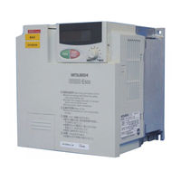
Mitsubishi Electric FR-E540 Instruction Manual (248 pages)
Transistorized Inverter
Brand: Mitsubishi Electric
|
Category: Inverter
|
Size: 3.25 MB
Table of Contents
-
Instruction Manual
1
-
Fire Prevention
3
-
Safety Instructions
3
-
Table of Contents
7
-
Chapter 1 Outline
11
-
Pre-Operation Information
12
-
Precautions for Operation
12
-
-
Basic Configuration
14
-
Structure
15
-
Appearance and Structure
15
-
Removal and Reinstallation of the Front Cover
16
-
Removal and Reinstallation of the Wiring Cover
18
-
Removal and Reinstallation of the Operation Panel
19
-
Removal of the Operation Panel Front Cover
20
-
Exploded View
21
-
-
-
Chapter 2 Installation and Wiring
23
-
Installation
24
-
Instructions for Installation
24
-
-
Wiring
26
-
Terminal Connection Diagram
26
-
Wiring of the Main Circuit
30
-
Wiring of the Control Circuit
35
-
Connection to the PU Connector
39
-
Connection of Stand-Alone Option Units
43
-
Design Information
47
-
-
Other Wiring
48
-
Power Supply Harmonics
48
-
Harmonic Suppression Guideline
49
-
Inverter-Generated Noise and Reduction Techniques
52
-
Leakage Currents and Countermeasures
56
-
Inverter-Driven 400V Class Motor
57
-
Peripheral Devices
58
-
Power Factor Improving Reactor
60
-
Power off and Magnetic Contactor (MC)
63
-
Instructions for UL, Cul
64
-
Instructions for Compliance with the European Directive
65
-
-
-
Chapter 3 Operation/Control
67
-
Pre-Operation Information
68
-
3.1.1 Types of Operation Modes
68
-
3.1.2 Power on
70
-
-
About the Operation Panel
71
-
Names and Functions of the Operation Panel
71
-
Monitor Display Is Changed by Pressing the [MODE] Key
72
-
Monitoring
72
-
Frequency Setting
73
-
Parameter Setting Method
73
-
Operation Mode
76
-
Help Mode
76
-
-
Operation
78
-
Pre-Operation Checks
78
-
PU Operation Mode (Operation Using the Operation Panel)
79
-
External Operation Mode (Operation Using the External Frequency Setting Potentiometer and External Start Signal)
81
-
Combined Operation Mode 1 (Operation Using both External Start Signal and Operation Panel)
82
-
Combined Operation Mode 2
83
-
-
-
Chapter 4 Parameters
85
-
Parameter List
86
-
List of Parameters Classified by Purpose of Use
92
-
Parameters Recommended to be Set by the User
94
-
-
Parameter Function Details
95
-
Torque Boost (Pr. 0, Pr. 46)
95
-
Output Frequency Range (Pr. 1, Pr. 2, Pr. 18)
96
-
Base Frequency, Base Frequency Voltage (Pr. 3, Pr. 19, Pr. 47)
97
-
Multi-Speed Operation (Pr. 4 to Pr. 6, Pr. 24 to Pr. 27, Pr. 232 to Pr. 239)
98
-
Acceleration/Deceleration Time (Pr. 7, Pr. 8, Pr. 20, Pr. 21, Pr. 44, Pr. 45)
99
-
Electronic Thermal Relay Function (Pr. 9, Pr. 48)
101
-
DC Injection Brake (Pr. 10 to Pr. 12)
102
-
Starting Frequency (Pr. 13)
103
-
Load Pattern Selection (Pr. 14)
104
-
Jog Operation (Pr. 15, Pr. 16)
105
-
Stall Prevention and Current Restriction (Pr. 22, Pr. 23, Pr. 66, Pr. 156)
106
-
Acceleration/Deceleration Pattern (Pr. 29)
109
-
Regenerative Brake Duty (Pr. 30, Pr. 70)
110
-
Frequency Jump (Pr. 31 to Pr. 36)
111
-
Speed Display (Pr. 37)
112
-
Frequency at 5V (10V) Input (Pr. 38)
113
-
Frequency at 20Ma Input (Pr. 39)
113
-
Up-To-Frequency Sensitivity (Pr. 41)
114
-
Output Frequency Detection (Pr. 42, Pr. 43)
114
-
Monitor Display (Pr. 52, Pr. 54)
115
-
Monitoring Reference (Pr. 55, Pr. 56)
117
-
Automatic Restart after Instantaneous Power Failure (Pr. 57, Pr. 58)
118
-
Remote Setting Function Selection (Pr. 59)
120
-
Shortest Acceleration/Deceleration Mode (Pr. 60 to Pr. 63)
123
-
Retry Function (Pr. 65, Pr. 67 to Pr. 69)
125
-
Applied Motor (Pr. 71)
127
-
PWM Carrier Frequency and Long Wiring Mode (Pr. 72, Pr. 240)
128
-
Voltage Input (Pr. 73)
130
-
Input Filter Time Constant (Pr. 74)
130
-
Reset Selection/Disconnected PU Detection/Pu Stop Selection (Pr. 75)
131
-
Parameter Write Disable Selection (Pr. 77)
133
-
Reverse Rotation Prevention Selection (Pr. 78)
134
-
Operation Mode Selection (Pr. 79)
134
-
General-Purpose Magnetic Flux Vector Control Selection (Pr. 80)
138
-
Offline Auto Tuning Function (Pr. 82 to Pr. 84, Pr. 90, Pr. 96)
139
-
Computer Link Operation (Pr. 117 to Pr. 124, Pr. 342)
145
-
Communication Specification
151
-
Setting Items and Set Data
153
-
-
PID Control (Pr. 128 to Pr. 134)
158
-
Frequency Setting Command Selection (Pr. 146)
166
-
Output Current Detection Function (Pr. 150, Pr. 151)
167
-
Zero Current Detection (Pr. 152, Pr. 153)
168
-
User Group Selection (Pr. 160, Pr. 173 to Pr. 176)
169
-
Actual Operation Hour Meter Clear (Pr. 171)
171
-
Input Terminal Function Selection (Pr. 180 to Pr. 183)
171
-
Output Terminal Function Selection (Pr. 190 to Pr. 192)
173
-
Cooling Fan Operation Selection (Pr. 244)
174
-
Slip Compensation (Pr. 245 to Pr. 247)
175
-
Earth (Ground) Fault Detection at Start (Pr. 249) (400V Class Does Not Have this Function)
176
-
Stop Selection (Pr. 250)
177
-
Output Phase Failure Protection Selection (Pr. 251)
178
-
Capacitor Life Alarm (Pr. 503, Pr. 504) (no Function for the 400V Class)
179
-
Meter (Frequency Meter) Calibration (Pr. 900)
180
-
Biases and Gains of the Frequency Setting Voltage (Current) and Built-In Frequency Setting Potentiometer (Pr. 902 to Pr. 905, Pr. 922, Pr. 923)
182
-
Adjustment Procedure
183
-
-
-
Chapter 5 Protective Functions
195
-
Errors (Alarms)
196
-
Error (Alarm) Definitions
196
-
To Know the Operating Status at the Occurrence of Alarm
205
-
Correspondence between Digital and Actual Characters
205
-
Resetting the Inverter
205
-
-
Troubleshooting
206
-
5.2.1 Motor Remains Stopped
206
-
5.2.2 Motor Rotates in Opposite Direction
206
-
5.2.3 Speed Greatly Differs from the Setting
207
-
5.2.4 Acceleration/Deceleration Is Not Smooth
207
-
5.2.5 Motor Current Is Large
207
-
5.2.6 Speed Does Not Increase
207
-
5.2.7 Speed Varies During Operation
207
-
5.2.8 Operation Mode Is Not Changed Properly
208
-
5.2.9 Operation Panel Display Is Not Operating
208
-
5.2.10 POWER Lamp Is Not Lit
208
-
5.2.11 Parameter Write Cannot be Performed
208
-
-
-
Chapter 6 Maintenance/Inspection
210
-
Precautions for Maintenance and Inspection
210
-
Check Items
210
-
Periodic Inspection
210
-
Insulation Resistance Test Using Megger
211
-
Pressure Test
211
-
Daily and Periodic Inspection
212
-
Replacement of Parts
215
-
Measurement of Main Circuit Voltages, Currents and Powers
220
-
-
-
Chapter 7 Specifications
223
-
Standard Specifications
224
-
Model Specifications
224
-
Common Specifications
228
-
Outline Drawings
230
-
-
APPENDIX 1 Instruction Code List
237
-
Appendix
237
-
APPENDIX 1 Instruction Code List
238
-
APPENDIX 2 When Using the Communication Option. (400V Class Only)
242
-
Advertisement
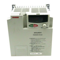
Mitsubishi Electric FR-E540 Instruction Manual (221 pages)
FR-E500 Series TRANSISTORIZED INVERTER
Brand: Mitsubishi Electric
|
Category: Inverter
|
Size: 3.5 MB
Table of Contents
-
Instruction Manual
1
-
Fire Prevention
3
-
Safety Instructions
3
-
Table of Contents
7
-
1 Outline
13
-
Pre-Operation Information
13
-
Precautions for Operation
13
-
-
Basic Configuration
15
-
Structure
16
-
Appearance and Structure
16
-
Removal and Reinstallation of the
17
-
Removal and Reinstallation of the Wiring Cover
19
-
Removal and Reinstallation of the Accessory Cover
20
-
Reinstallation and Removal of the Control Panel
21
-
Removal of the Control Panel (FR-PA02- )
22
-
Front Cover
22
-
Exploded View
23
-
-
-
2 Installation and Wiring
25
-
Installation
25
-
Instructions for Installation
25
-
-
Wiring
27
-
Terminal Connection Diagram
27
-
Wiring of the Main Circuit
31
-
Wiring of the Control Circuit
36
-
Connection to the PU Connector
41
-
Connection of Stand-Alone Option Units
44
-
Design Information
47
-
-
Other Wiring
48
-
Power Supply Harmonics
48
-
Japanese Harmonic Suppression Guideline
49
-
Inverter-Generated Noise and Reduction Techniques
49
-
Leakage Currents and Countermeasures
53
-
Inverter-Driven 400V Class Motor
54
-
Peripheral Devices
55
-
Instructions for Compliance with the UL and CSA Standards
59
-
Instructions for Compliance with the European Standards
60
-
-
-
3 Operation/Control
62
-
Pre-Operation Information
63
-
Types of Operation Modes
63
-
Power on
65
-
-
About the Control Panel
66
-
Names and Functions of the Control Panel (FR-PA02- )
66
-
MODE Key
66
-
Monitoring
67
-
Frequency Setting
67
-
Parameter Setting Method
68
-
Operation Mode
70
-
Help Mode
70
-
-
Operation
73
-
Pre-Operation Checks
73
-
External Operation Mode (Operation Using the External Frequency Setting Potentiometer and External Start Signal)
74
-
PU Operation Mode (Operation Using the Control Panel)
75
-
Combined Operation Mode 1 (Operation Using both External Start Signal and Control Panel)
76
-
Combined Operation Mode 2
77
-
-
-
4 Parameters
79
-
Parameter List
79
-
List of Parameters Classified by Purpose of Use
85
-
Parameters Recommended to be Set by the User
87
-
-
Parameter Function Details
88
-
Torque Boost (Pr. 0, Pr. 46)
88
-
Output Frequency Range (Pr. 1, Pr. 2, Pr. 18)
89
-
Base Frequency, Base Frequency Voltage (Pr. 3, Pr. 19, Pr. 47)
90
-
Multi-Speed Operation (Pr. 4, Pr. 5, Pr. 6, Pr. 24 to Pr. 27, Pr. 232 to Pr. 239)
91
-
Acceleration/Deceleration Time (Pr. 7, Pr. 8, Pr. 20, Pr. 21, Pr. 44, Pr. 45)
92
-
Electronic Overcurrent Protection (Pr. 9, Pr. 48)
94
-
DC Dynamic Brake (Pr. 10 to Pr. 12)
95
-
-
Starting Frequency (Pr. 13)
96
-
Load Pattern Selection (Pr. 14)
97
-
Jog Operation (Pr. 15, Pr. 16)
98
-
Stall Prevention (Pr. 22, Pr. 23, Pr. 66)
99
-
Acceleration/Deceleration Pattern (Pr. 29)
101
-
Regenerative Brake Duty (Pr. 30, Pr. 70)
102
-
Frequency Jump (Pr. 31 to Pr. 36)
103
-
Speed Display (Pr. 37)
104
-
Frequency at 5V (10V) Input (Pr. 38)
105
-
Frequency at 20Ma Input (Pr. 39)
105
-
Up-To-Frequency Sensitivity (Pr. 41)
106
-
Output Frequency Detection (Pr. 42, Pr. 43)
106
-
Monitor Display (Pr. 52, Pr. 54, Pr. 158)
108
-
Monitoring Reference (Pr. 55, Pr. 56)
110
-
Automatic Restart after Instantaneous Power Failure
111
-
Remote Setting Function Selection (Pr. 59)
112
-
Shortest Acceleration/Deceleration Mode (Pr. 60 to Pr. 63)
113
-
Retry Function (Pr. 65, Pr. 67 to Pr. 69)
115
-
Applied Motor (Pr. 71)
117
-
PWM Carrier Frequency (Pr. 72, Pr. 240)
118
-
Voltage Input (Pr. 73)
119
-
Input Filter Time Constant (Pr. 74)
120
-
Reset Selection/Pu Disconnection Detection/Pu Stop Selection (Pr. 75)
120
-
Selection (Pr)
120
-
Parameter Write Inhibit Selection (Pr. 77)
122
-
Reverse Rotation Prevention Selection (Pr. 78)
123
-
Operation Mode Selection (Pr. 79)
124
-
General-Purpose Magnetic Flux Vector Control Selection (Pr. 80)
127
-
Offline Auto Tuning Function (Pr. 82 to Pr. 84, Pr. 90, Pr. 96)
129
-
Computer Link Operation (Pr. 117 to Pr. 124)
135
-
Setting Items and Set Data
141
-
PID Control (Pr. 128 to Pr. 134)
146
-
Output Current Detection Function (Pr. 150, Pr.151)
154
-
Zero Current Detection (Pr. 152, Pr.153)
155
-
Stall Prevention Function and Current Limit Function (Pr. 156)
156
-
User Group Selection (Pr. 160, Pr. 173 to Pr. 176)
158
-
Actual Operation Hour Meter Clear (Pr. 171)
160
-
Input Terminal Function Selection (Pr. 180 to Pr. 183)
160
-
Output Terminal Function Selection (Pr. 190 to Pr. 192)
162
-
Cooling Fan Operation Selection (Pr. 244)
163
-
Slip Compensation (Pr. 245 to Pr. 247)
164
-
Ground Fault Detection at Start (Pr. 249)
165
-
(400V Class Does Not Have this Function)
165
-
Stop Selection (Pr. 250)
166
-
Meter (Frequency Meter) Calibration (Pr. 900) (200V Class, 100V Class)
168
-
Meter (Frequency Meter) Calibration (Pr. 901) (400V Class)
170
-
Biases and Gains of the Frequency Setting Voltage (Current)
172
-
(Pr. 902 to Pr. 905)
172
-
Adjustment Procedure
173
-
-
-
5 Protective Functions
179
-
Errors (Alarms)
179
-
Error (Alarm) Definitions
179
-
To Know the Operating Status at the Occurrence of Alarm
187
-
Correspondence between Digital and Actual Characters
187
-
Resetting the Inverter
187
-
-
Troubleshooting
188
-
Motor Remains Stopped
188
-
Motor Rotates in Opposite Direction
188
-
Speed Greatly Differs from the Setting
189
-
Acceleration/Deceleration Is Not Smooth
189
-
Motor Current Is Large
189
-
Speed Does Not Increase
189
-
Speed Varies During Operation
189
-
Operation Mode Is Not Changed Properly
190
-
Control Panel Display Is Not Operating
190
-
POWER Lamp Is Not Lit
190
-
Parameter Write Cannot be Performed
190
-
-
Precautions for Maintenance and Inspection
191
-
Check Items
191
-
Periodic Inspection
191
-
Insulation Resistance Test Using Megger
192
-
Pressure Test
192
-
Daily and Periodic Inspection
193
-
Replacement of Parts
196
-
Measurement of Main Circuit Voltages, Currents and Powers
201
-
-
-
6 Specifications
205
-
Standard Specifications
205
-
Model Specifications
205
-
Common Specifications
208
-
Outline Drawings
210
-
-
-
Appendix
216
-
Appendix 1 Data Code List
217
Mitsubishi Electric FR-E540 Instruction Manual (202 pages)
Large Capacity Inverter
Brand: Mitsubishi Electric
|
Category: Inverter
|
Size: 4.14 MB
Table of Contents
-
Table of Contents
2
-
Outline
7
-
Pre-Operation Information
8
-
Precautions for Operation
8
-
Basic Configuration
10
-
Structure
11
-
Appearance and Structure
11
-
Removal and Reinstallation of the
12
-
Removal and Reinstallation of the Wiring Cover
13
-
Removal and Reinstallation of the Accessory Cover
14
-
Reinstallation and Removal of the Control Panel
15
-
Removal of the Operation Panel (FR-PA02- )
17
-
Front Cover
17
-
Exploded View
17
-
Installation and Wiring
19
-
Installation
19
-
Instructions for Installation
19
-
Wiring
21
-
Terminal Connection Diagram (When Source Logic Is Selected)
21
-
Wiring of the Main Circuit
25
-
Wiring of the Control Circuit
30
-
Connection to the PU Connector
34
-
Connection of Stand-Alone Option Units
37
-
Design Information
39
-
Other Wiring
40
-
Power Supply Harmonics
40
-
Japanese Harmonic Suppression Guideline
41
-
Inverter-Generated Noise and Reduction Techniques
41
-
Leakage Currents and Countermeasures
45
-
Inverter-Driven 400V Class Motor
46
-
Peripheral Devices
47
-
Instructions for Compliance with the UL and CSA Standards
50
-
Instructions for Compliance with the European Standards
51
-
Operaton
55
-
Pre-Operation Information
55
-
Types of Operation Modes
55
-
Power on
57
-
About the Control Panel
58
-
Names and Functions of the Control Panel (FR-PA02- )
58
-
Control Panel Mode Is Changed by Pressing the
59
-
MODE Key
59
-
Monitoring Mode
59
-
Frequency Setting Mode
60
-
Parameter Setting Mode
60
-
Operation Mode
62
-
Help Mode
62
-
Operation
64
-
Pre-Operation Checks
64
-
External Operation Mode (Operation Using the External Frequency Setting Potentiometer and External Start Signal)
65
-
PU Operation Mode (Operation Using the Control Panel)
66
-
Combined Operation Mode 1 (Operation Using both External Signal and Control Panel)
67
-
Combined Operation Mode 2
67
-
Parameters
70
-
Parameter List
70
-
List of Parameters Classified by Purpose of Use
76
-
Parameters Recommended to be Set by the User
78
-
Parameter Function Details
79
-
Torque Boost (Pr. 0, Pr. 46)
79
-
Output Frequency Range (Pr. 1, Pr. 2, Pr. 18)
80
-
Base Frequency, Base Frequency Voltage (Pr. 3, Pr. 19, Pr. 47)
81
-
Multi-Speed Operation
82
-
(Pr. 4, Pr. 5, Pr. 6, Pr. 24 to Pr. 27, Pr. 232 to Pr. 239)
82
-
Acceleration/Deceleration Time (Pr. 7, Pr. 8, Pr. 20, Pr. 21, Pr. 44, Pr. 45)
83
-
Electronic Overcurrent Protection (Pr. 9, Pr. 48)
85
-
DC Dynamic Brake (Pr. 10 to Pr. 12)
86
-
Starting Frequency (Pr. 13)
87
-
Load Pattern Selection (Pr. 14)
88
-
Jog Operation (Pr. 15, Pr. 16)
89
-
Stall Prevention (Pr. 22, Pr. 23, Pr. 66)
90
-
Acceleration/Deceleration Pattern (Pr. 29)
92
-
Regenerative Brake Duty (Pr. 30, Pr. 70)
93
-
Frequency Jump (Pr. 31 to Pr. 36)
94
-
Speed Display (Pr. 37)
95
-
Frequency at 5V (10V) Input (Pr. 38)
96
-
Frequency at 20Ma Input (Pr. 39)
96
-
Up-To-Frequency Sensitivity (Pr. 41)
97
-
Output Frequency Detection (Pr. 42, Pr. 43)
98
-
Monitor Display (Pr. 52, Pr. 158)
99
-
Monitoring Reference (Pr. 55, Pr. 56)
101
-
Automatic Restart after Instantaneous Power Failure (Pr. 57, Pr. 58)
102
-
Remote Setting Function Selection (Pr. 59)
103
-
Shortest Acceleration/Deceleration Mode (Pr. 60 to Pr. 63)
104
-
Retry Function (Pr. 65, Pr. 67 to Pr. 69)
106
-
Applied Motor (Pr. 71)
108
-
PWM Carrier Frequency (Pr. 72, Pr. 240)
109
-
Voltage Input (Pr. 73)
110
-
Input Filter Time Constant (Pr. 74)
111
-
Reset Selection/Pu Disconnection Detection/Pu Stop Selection (Pr. 75)
111
-
Parameter Write Inhibit Selection (Pr. 77)
113
-
Reverse Rotation Prevention Selection (Pr. 78)
114
-
Operation Mode Selection (Pr. 79)
115
-
General-Purpose Magnetic Flux Vector Control Selection (Pr. 80)
119
-
Offline Auto Tuning Function (Pr. 82 to Pr. 84, Pr. 90, Pr. 96)
120
-
Computer Link Operation (Pr. 117 to Pr. 124)
126
-
PID Control (Pr. 128 to Pr. 134)
137
-
Output Current Detection Function (Pr. 150, Pr. 151)
145
-
Zero Current Detection (Pr. 152, Pr. 153)
146
-
Stall Prevention Function and Current Limit Function (Pr. 156)
147
-
User Group Selection (Pr. 160, Pr. 173 to Pr. 176)
150
-
Actual Operation Hour Meter Clear (Pr. 171)
152
-
Input Terminal Function Selection (Pr. 180 to Pr. 183)
152
-
Output Terminal Function Selection (Pr. 190 to Pr. 192)
154
-
Cooling Fan Operation Selection (Pr. 244)
155
-
Slip Compensation (Pr. 245 to Pr. 247)
156
-
Stop Selection (Pr. 250)
157
-
Meter (Frequency Meter) Calibration (Pr. 901)
159
-
Biases and Gains of the Frequency Setting Voltage (Current)
161
-
(Pr. 902 to Pr. 905)
161
-
Protective Functions
168
-
Errors (Alarms)
168
-
Error (Alarm) Definitions
168
-
To Know the Operating Status at the Occurrence of Alarm
176
-
Correspondence between Digital and Actual Characters
176
-
Resetting the Inverter
176
-
Troubleshooting
177
-
Motor Remains Stopped
177
-
Motor Rotates in Opposite Direction
177
-
Speed Greatly Differs from the Setting
178
-
Acceleration/Deceleration Is Not Smooth
178
-
Motor Current Is Large
178
-
Speed Does Not Increase
178
-
Speed Varies During Operation
178
-
Operation Mode Is Not Changed Properly
179
-
Control Panel Display Is Not Operating
179
-
POWER Lamp Is Not Lit
179
-
Parameter Write Cannot be Performed
179
-
Precautions for Maintenance and Inspection
180
-
Check Items
180
-
Periodic Inspection
180
-
Insulation Resistance Test Using Megger
181
-
Pressure Test
181
-
Replacement of Parts
185
-
Measurement of Main Circuit Voltages, Currents and Powers
189
-
Specifications
191
-
Standard Specifications
192
-
Model Specifications
192
-
Common Specifications
194
-
Outline Drawings
196
-
Appendix
198
-
Appendix 1 Data Code List
199
Advertisement
Advertisement
Related Products
-
Mitsubishi Electric FR-E540-0.4K
-
Mitsubishi Electric FR-E540-0.75K
-
Mitsubishi Electric FR-E540-2.2K
-
Mitsubishi Electric FR-E540-3.7K
-
Mitsubishi Electric FR-E540-5.5K
-
Mitsubishi Electric FR-E540-7.5K
-
Mitsubishi Electric FR-E540-0.4K-EC
-
Mitsubishi Electric FR-E540-0.75K-EC
-
Mitsubishi Electric FR-E540-1.5K-EC
-
Mitsubishi Electric FR-E540-2.2K-EC
Mitsubishi Electric Categories
![]()
Air Conditioner
Controller
![]()
Projector
Inverter
Heat Pump
More Mitsubishi Electric Manuals
Преобразователи частоты Mitsubishi Electric компактной серии FR-E500
Благодаря великолепным возможностям и функциональному набору, преобразователи частоты Mitsubishi Electric FR-E500 (до 7,5 кВт) получили очень широкое распространение практически во всех отраслях промышленности. Преобразователи имеют автоматическое адаптивное векторное управление, которое позволяет сохранить момент на низких оборотах двигателя.
Встроенный интерфейс RS-485 позволяет включить в сеть до 32 преобразователей.
Поддерживаются сети: Profibus/DP, DeviceNet and CC-Link.
Наша компания успешно применяет этот тип преобразователей для управления двигателями тянущего механизма, а также других, где требуется постоянство скорости или обеспечение высокого момента на низких скоростях.
Применение преобразователей FR-E500
-
Насосы и вентиляторы
-
Упаковочные и дозирующие машины
-
Обрабатывающи станки
-
Конвейеры и транспортеры
-
Текстильные станки
-
Мешалки
-
Эскалаторы
-
Лебедки
-
Экструдеры
Отличительные особенности
-
Диапазон выходных частот: 0,2 — 400 Гц
-
Векторное управление с автоматической настройкой на двигатель
-
15 программируемых установок скорости
-
Перегрузка по току 150 % в течение 1 мин
-
Встроенный ПИД-регулятор
-
Встроенный тормозной транзистор
-
Встроенный интерфейс RS485
Не знаете как определиться? Ознакомьтесь подробнее в нашей статье частотный преобразователь и как правильно его выбрать!
002 — Allen Bradley PowerFlex4 Руководство пользователя (94)_rus.pdf 1.19 MB
Руководство пользователя на русском языке 94 страницы.
003 — ALTIVAR 18 Инструкция (31)_rus.pdf 453.74 KB
Инструкция к частотным преобразователям «ALTIVAR 18 » на русском языке 31 страница.
003 — ALTIVAR 18 Руководство (127)_eng.pdf 804.83 KB
Руководство по эксплуатации ALTIVAR 18 на английском языке 127 страниц.
003 — ALTIVAR 28 — Руководство по эксплуатации (48)_rus 860.81 KB
Руководство по эксплуатации для частотного преобразователя «Altivar 28». На русском языке 48 страниц.
003 — ALTIVAR 31 — Руководство по программированию (77)_rus.pdf 1.82 MB
Инструкция по программированию инвертора Altivar 31. На русском языке 77 страниц.
003 — ALTIVAR 31- Руководство по эксплуатации (17)_rus.pdf 689.52 KB
Руководство по эксплуатации и схема подключения для инверторов Altivar 31. На русском языке 17 страниц.
003 — ALTIVAR 312 Руководство по программированию (120)_rus 2.4 MB
Руководство по программированию частотного преобразователя ALTIVAR 312. а русском языке 120 страниц.
003 — ALTIVAR 58 — каталог и тамже размеры и вес (97)_rus 1.95 MB
Каталог. Там можна найти размеры и вес частотника. Всего 97 страниц на русском языке.
003 — ALTIVAR58 — руководство по программированию (59)_rus 1.93 MB
Руководство по программированию частотника ALTIVAR 58. На русском языке 59 страниц.
004 — Danfoss VLT 2800 Manua(120)_rus.pdf 3.1 MB
Руководство к частотному преобразователю Danfoss VLT 2800. На русском языке 120 страниц.
004 — DANFOSS VLT5000 (223)_rus 8.17 MB
Инструкция на русском языке
004 — Инструкция по эксплуатации_FC300(98)_rus .pdf 3.31 MB
Инструкция по эксплуатации к частотному преобразователю DANFOOS FC300. На русском языке 98 страниц.
004 — Руководство для проэктирования_FC300 (196)_rus.pdf 3.33 MB
Руководство для проэктирования к частному преобразователю DANFOOS FC300. На русском языке 196 страниц.
004 — Руководство по программированию_FC300(219)_rus.pdf 4.52 MB
Руководство по программированию к частотному преобразователю DANFOOS FC300. На русском языке 219 страниц.
006 — FUJI AF300 E11 Manual (146)_engl 2.01 MB
Инструкция к частотному преобразователю FUJI AF300 E11 на английском языке 146 страниц (отдельно есть перевод параметров на русском языке)
006 — FUJI AF300E$ (Instruction book GEI_100211G) (134)_engl 1.02 MB
Инструкция к частотному преобразователю FUJI AF-300E$ GE на английском языке 134 страницы. Отдельно на русском языке есть таблица праметров для программирования преобразователя.
006 — FUJI FRENIC FRN-G11S (188)_rus 3.67 MB
Инструкция на русском языке 188 страниц к частотнику FUJI FRN-G11S
006 — FUJI FRENIC 5000G9S_P9S Инструкция (128)_engl 16.21 MB
Инструкция к частотному преобразователю FUJI FRENIC 5000G9S_P9S. На английском языке 128 страниц
006 — FUJI FRENIC 5000P9S (101)_немец 2.21 MB
Инструкция к частотнику FUJI FRENIC 5000P9S на немецком языке — 101 страница.
007 — HITACHI L100 Manual (163)_engl 3.38 MB
HITACHI L100 Instruction Manual на английском языке 163 страницы.
007 — HITACHI L100 Инструкция (76)_rus 1.02 MB
Инструкция к частотному преобразователю HITACHI L100 на русском языке 76 страниц.
007 — HITACHI L200 Инструкция (276)_rus 6.5 MB
Инструкция к частотному преобразователю HITACHI L200 на русском языке 276 страниц.
007 — HITACHI L200 Руководство по эксплуатации (124)_rus 2.23 MB
HITACHI L200 Руководство по эксплуатации 124 страницы на Русском языке.
007 — HITACHI J300 — Инструкция по эксплуатации (109)_rus 1.39 MB
Инструкция по эксплуатации к частотному преобразователю HITAGHI J300 на русском языке 109 страниц.
007 — HITACHI L100 Инструкция (76)_rus 1.02 MB
Инструкция для частотного преобразователя HITACHI L100 на русском языке 76 страниц.
007 — Hitachi L300P Руководство (103)_rus.pdf 2.4 MB
Инструкция к частотному преобразователю HITACHI L300P на русском языке.
007 — HITACHI SJ100 Instruction manual (213)_engl 5.02 MB
Инструкция к частотному преобразователю HITACHI SJ100 на английском языке 213 страниц.
007 — HITACHI SJ300 Manual (130)_rus 2.15 MB
Инструкция к частотному преобразователю Hitachi SJ300 на русском языке.
007 — HITCHI J300 Instruction Manual (130)_engl 693.04 KB
Инструкция к частотному преобразователю HITCHI J300 на английском языке 130 страниц.
009 — LENZE SMD инструкция по эксплуатации (24)_rus 1.29 MB
Инструкция на русском языке 24 страницы.
011 — Magnetek GPD 505 Manual (151)_eng 2.03 MB
Инструкция к частотному преобразователю Magnetek GPD 505 на английском языке 151 страница.
011 — Magnetek GPD205 Техническое реководство (88)_eng.pdf 905.9 KB
Техническое руководство по частотным преобразователям Magnetek GPD205. Файл на английском языке из 88 страниц.
012 — MITSUBISHI FR_A240 Инструкция (124)_eng.pdf 8.41 MB
Инструкция к частотному преобразователю Mitsubishi FR-A240E на английском языке 128странец. При необходимости могу сделать таблицу настроек параметров на русском.
012 — MITSUBISHI FR-A044 — Инструкция (167)_eng.pdf 9.28 MB
Инструкция к частотным преобразователям серии MITSUBISHI FR-A044, на английском языке 167 страниц.
012 — MITSUBISHI FR-A044 Руководство (167)_eng.pdf 9.28 MB
Инструкция на частотные преобразователи MITSUBISHI FR-A044. На английском языке 167 страниц.
012 — MITSUBISHI FR-A500 Инструкция (186)_rus.pdf 2.56 MB
Инструкция на русском языке из 186 страниц
012 — MITSUBISHI FR-E500 Инструкция (194)_rus.pdf 2.8 MB
Инструкция на русском языке, 194 страницы.
012 — MITSUBISHI FR-E520 ( E540 ) Руководство по эксплуатации (278)_rus.pdf 4.5 MB
Руководство по эксплуатации частотных преобразователей Mitsubishi FR-E520 (E540). На русском языке 278 страниц.
012 — MITSUBISHI FR-E700 Руководство по установке (28)_rus.pdf 1.2 MB
Руководство по установке к частотному преобразователю MITSUBISHI FR E740. На русском языке 28 страниц.
012 — Mitsubishi FR-E700_Руководство (310)_eng.pdf 17.87 MB
Инструкция к частотным преобразователям Mitsubishi FR-E700. Файл на английском языке из 310 страниц.
012 — MITSUBISHI FR-F700 руководство по установке(24)_rus 1.09 MB
Руководство по установке частотного преобразователя MITSUBISHI FR-F700. На русском языке 24 страницы.
012 — MITSUBISHI FR-F740 руководство по эксплуатации(506)_rus 13.83 MB
Руководство по эксплуатации частотного преобразователя MITSUBISHI FR-F740 . На русском языке 506 страниц.
012 — MITSUBISHI FR-S500 (E500)(F700)(A700) — Руководство для начинающего (108)_rus.pdf 2.71 MB
Руководство для начинаючего. На русском языке 108 страниц.
012 — Mitsubishi FR-S500 Руководство по эксплуатации (84)_rus.pdf 1.72 MB
Руководство по эксплуатации частотных преобразователей Mitsubishi FR-S500. Файл на русском языке, 84 страницы.
015 — IDM G5+SERIES Руководство пользователя_engl.pdf 1.75 MB
Руководство пользователя на английском языке.
015 — OMRON 3G3JV SYSDRIVE_Руководство пользователя (161)_rus.pdf 2.08 MB
Руководство пользователя на частотные преобразователи OMRON 3G3JV. Текст на русском языке 161 страница.
015 — OMRON F7 Быстрый старт (146p) (169)_rus.pdf 5.29 MB
015 — OMRON F7 Quick start(146p) (169)_rus.pdf
015 — OMRON F7 Руководство по эксплуатации (367)_rus.pdf 9.68 MB
Руководство по експлуатации на русском языке (367 страниц).
015 — OMRON V7 Руководство пользователя (247)_rus.pdf 5.32 MB
Руководство пользователя по Инверторам OMRON V7 на русском языке 247страниц.
015 — OMRON VS Mini J7 Руководство пользователя (176)_rus.pdf 3.1 MB
Руководство пользователя на русскоя языке 176 страниц.
016 — SAFTRONICS FP5_GP5 Руководство (101)_eng.pdf 5.23 MB
Руководство по эксплуатации на английском языке 101 страница. (Дополнительно имеется таблица настройки параметров на русском языке).
016 — Saftronics FP5- GP5 Техническое руководство (108)_eng.pdf 1.31 MB
Техническое руководство на английском языке 108 страниц.
016 — Saftronics PC7 Руководство (225)_eng.pdf 2.19 MB
Руководство к частотному преобразователю SAFTRONICS PC7. На английском языке 225 страниц. На русском языке можно почитать инструкцию от частотного преобразователя OMRON V7. Эти частотники очень похожи друг на друга.
017 — Combivert F4C Руководство по программированию (278)_rus 8.16 MB
Siemens Combivert KEB F4C — Руководство по программированию на русском языке 278 страниц.
017 — MIKROMASTER MM440 Руководство по эксплуатации(140)_rus 5.85 MB
Руководство по эксплуатации к частотному преобразователю Siemens MM440 на русском языке 140 страниц.
017 — MM440_Описание параметров (169)_rus 2.04 MB
Описание параметров к частотному преобразователю Siemens Micromaster MM440. На русском языке 169 страниц.
017 — SIEMENS MM420 — Руководство по эксплуатации (130)_rus 6.87 MB
Руководство по эксплуатации к частотному преобразователю SIEMENS MM420. На русском языке 130 страниц.
017 — Siemens SED2 Руководство (81)_rus 2.1 MB
Инструкция к частотному преобразователю Siemens SED2 81 страница на Русском языке.
019 — TOSHIBA G3 (134)_eng.pdf 1.64 MB
Инструкция к частотному преобразователю «Toshiba G3» на английском языке.
019 — Toshiba Tosvert VF-S11 Инструкция (258)_rus 3.79 MB
Toshiba Tosvert VF-S11 Инструкция 258 страниц на русском языке
019 — TOSHIBA VF-S9 (198)_engl 4 MB
TOSHIBA VF-S9 инструкция на английском языке 198 страниц.
020 -COMMANDER SK — Расширенное руководство пользователя (202)_rus.PDF 5.68 MB
Расширенное руководство пользователя, на русском языке 202 страницы.
020 — Commder_SE Руководство пользователя (86)_rus 1.19 MB
Руководство пользователя к частотному преобразователю CONTROL TECHNIQUES COMANDER SE на русском языке 86 страниц.
020 — Commder_SE Руководство пользователя (86)_rus 1.19 MB
Инструкция к частотному преобразователю COMANDER SE фирмы CONTROL TECHNIQUES. На русском языке 86 страниц.
022 — Yaskawa P7 Руководство пользователя (252)_eng.pdf 3.85 MB
Руководство пользователя на частотные преобразователи Yaskawa P7. Состоит из 252 страниц на английском языке
022 — Yaskawa VS-606 V7 Краткая инструкция (23)_rus .pdf 3.66 MB
Краткая инструкция на русском языке к частотным преобразователям Yaskawa VS-606 V7.
022 — YASKAWA F7 Руководство по эксплуатации (374)_rus.pdf 6.95 MB
Руководство по эксплуатации YASKAWA F7 на русском языке 374 страницы.
022 — Yaskawa GPD315 V7 Руководство (162)_eng.pdf 2.13 MB
Руководство на частотные преобразователи «Yaskawa GPD315 V7». На английском языке 162 страницы.
022 — Yaskawa GPD506_P5 Техническое руководство (168)_eng 3.68 MB
Техническое руководство к частотным преобразователям серии GPD506/P5 фирм Yaskawa и Magnetek (168 страниц на английском языке)
022 — Yaskawa J7 Техническое руководство (96)_eng 3.21 MB
Техническое руководство к инверторам серии J7. На английском языке 96 страниц.
022 — Yaskawa V7 and V74X Drives Техническое руководство (155)_eng.pdf 2.45 MB
Руководство по експлуатации к частотным преобразователям Yaskawa V7, на английском языке 155страниц. Очень похожая на нее, Инструкция к частному преобразователю OMRON V7 (на русском языке), отличается только некоторыми параметрами. Инструкция на OMRON находится в вкладке «ИНСТРУКЦИИИ ПОЧАСТОТНИКАМ».
022 — Yaskawa V7 and V74X Инструкция (64)_eng.pdf 3.44 MB
Инструкция на частотные преобразователи серии Yaskawa V7 and V74X. На английском языке 64 страницы.
022 — Yaskawa V7 and V74X Руководство (158)_eng.pdf 2.23 MB
Инструкция к частотным преобразователям Yaskawa V7, на английском языке 158страниц. Очень похожая на нее, Инструкция к частному преобразователю OMRON V7 (на русском языке), отличается только некоторыми параметрами.
022 — YASKAWA V7 Инструкция по быстрому запуску (29)_rus.pdf 3.57 MB
Руководство по быстрому запуску частотных преобразователей » YASKAWA V7 «, на русском языке 29 страниц.
022 — Yaskawa VS Mini J7 Инструкция (117)_eng.pdf 2.06 MB
Инструкция на частотные преобразователи » Yaskawa VS Mini J7 «. Состоит из 117страниц на англйском языке
022 — Yaskawa VS Mini Руководство (77)_eng.pdf 2.95 MB
Руководство по эксплуатации частотных преобразователей Yaskawa VS Mini. Файдл на английском языке 77 страниц.
022 — Yaskawa VS mini, J7 and V7 Инструкция (76)_eng.pdf 2.64 MB
Инструкция на частотные преобразователи Yaskawa VS mini, J7 and V7. На английском языке 76 страниц.
022 — Yaskawa VS-606 V7 Инструкция (174)_eng.pdf 1.75 MB
Инструкция на частотные преобразователи Yaskawa VS-606 V7. На английском языке 174 страницы.
022 — Yaskawa VS-606-V7 Руководство (166)_eng.pdf 3.96 MB
Руководство по експлуатации к частотным преобразователям Yaskawa VS, на английском языке 166страниц. Очень похожая на нее, Инструкция к частному преобразователю OMRON VS (на русском языке), отличается только некоторыми параметрами. Инструкция на OMRON находится в вкладке «ИНСТРУКЦИИИ ПОЧАСТОТНИКАМ».
023 — NORDAC SK 700E Руководство по эксплуатации (120)_rus 14.63 MB
Руководство по эксплуатации к частотному преобразователю NORDAC SK 700E на русскоя языке 120 страниц.
028 — INVT CHE100_manual (125)_engl 1.86 MB
Инструкция к частотному преобразователю INVT CHE100 125 страниц на Английском языке.
028 — INVT CHE100_manual (125)_engl 1.86 MB
Инструкция на английском языке 125 страниц.
028 — INVT CHF100 (42)_rus 1.48 MB
Краткая инструкция к частотному преобразователю INVT CHF100 на Русском языке.
030 — Drivecon XT Series Instruktion Manual (120)_engl 2.76 MB
Drivecon XT Series. Инструкция на английском языке 120 страниц. На русском языке имеется много инструкций для частотника VACON, это тоже самое.
030 — Drivecon XT Service Manual (59)_engl 2.12 MB
Drivecon XT. Service Manual (59)_engl.
030 — VACON — Преобразователи чачтоты серии NXP-C (108)_rus 3.63 MB
Преобразователи чачтоты VACON серии NXP/C. На русском языке 108 страниц.
030 — VACON NX Руководство по прикладным программам (266)_rus 3.55 MB
VACON NX. Руководство по прикладным программам на русском языке 266 страниц.
800 — EFECTOR500 PN-2224 — датчик давления 10атм (4)_rus 100.77 KB
EFECTOR500 PN-2224 — датчик давления
800 — EFECTOR500 PN-2224 — Инструкция по эксплуатации (20)_rus.PDF 367.92 KB
Инструкция по эксплуатации к датчику давления (регулятору давления) EFECTOR500 PN-2224. На русском языке 20 страниц.
801 — XMLG_каталог датчиков 710.74 KB
Характеристики датчиков серии XMLG
997 — Файл настроек частотника FR-E540 616 B
Файл с параметрами для частотника Mitsubishi FR-E540. Открывается программой «VFD Setup 3.11 «. Частотник настроен для работы в амплитудно-частотном режиме от сети 380В. Тепловая защита двигателя отключена. Режим управления терминальный (т.е. от внешних выключателей и потенциометра). Максимальная частота 50Гц. Время разгона/торможения 5 сек.
998 — Как подключить частотник FR-E540 к порту RS485 881.12 KB
Как подключить частотник FR-E540 к порту RS485
999 — Что такое частотник и зачем он нужен.mht 203.19 KB
Эта статья для людей, чья специальность не предполагает глубоких знаний в области электропривода, но в силу обстоятельств которые вынуждены с ним столкнуться. Здесь можно будет найти некоторые ответы на вопросы что такое частотник и как устроен электродвигатель.