Mitsubishi i-MiEV: Руководства по эксплуатации
Материал из MMC Manuals
Перейти к навигации
Перейти к поиску
Руководства по эксплуатации Mitsubishi i-MiEV. Брошюры, каталоги, спецификации, карты технического обслуживания.
↑ Mitsubishi i-MiEV
![]()
| Язык/Language: | Русский • English |
|---|
Брошюры, каталоги, спецификации
- Каталог Mitsubishi i-MiEV MY 2017 (спецификация для Европы), eng., pdf, 8,25 МБ
- Каталог Mitsubishi i-MiEV MY 2017/5 (спецификация для Европы), eng., pdf, 7,79 МБ
- Каталог оригинальных аксессуаров для Mitsubishi i-MiEV MY 2013, рус., pdf, 1,54 МБ
Руководства по эксплуатации
- Краткое руководство Mitsubishi i-MiEV (Россия), рус., pdf, 328 кБ
- Краткое руководство Mitsubishi i-MiEV MY 2012 (North America), eng., pdf, 5,19 МБ
- Краткое руководство Mitsubishi i-MiEV MY 2015 (North America), eng., pdf, 2,49 МБ
- Листовка Mitsubishi i-MiEV MY 2013, eng., pdf, 1,84 МБ
- Руководство по эксплуатации Mitsubishi i-MiEV MY 2012 (Europe), eng., pdf, 12,1 МБ
- Руководство по эксплуатации Mitsubishi i-MiEV MY 2012.5 (Europe), eng., pdf, 14,1 МБ
- Руководство по эксплуатации Mitsubishi i-MiEV MY 2013 (Europe), eng., pdf, 12,9 МБ
- Руководство по эксплуатации Mitsubishi i-MiEV MY 2012 (North America), eng., pdf, 12,5 МБ
- Руководство по эксплуатации Mitsubishi i-MiEV MY 2015 (North America), eng., pdf, 26,8 МБ
- Руководство по эксплуатации Mitsubishi i-MiEV MY 2016 (North America), eng., pdf, 7,82 МБ
- Руководство по эксплуатации Mitsubishi i-MiEV MY 2017 (North America), eng., pdf, 7,95 МБ
- Manuals
- Brands
- Mitsubishi MOTORS Manuals
- Automobile
- i-MiEV
- Owner’s manual
-
Contents
-
Table of Contents
-
Bookmarks
Related Manuals for Mitsubishi MOTORS i-MiEV
Summary of Contents for Mitsubishi MOTORS i-MiEV
-
Page 1
OWNER’S MANUAL -M EV — ENGLISH — OHAE12E5… -
Page 2
Repairs to your vehicle: RHD: Right-Hand Drive Vehicles in the warranty period: All warranty repairs must be carried out by a MITSUBISHI MOTORS Au- thorized Service Point. Vehicles outside the warranty period: Where the vehicle is repaired is at the discretion of the owner. -
Page 3
Table of contents Overview General information Charging Locking and unlocking Seat and seat belts Instruments and controls Starting and driving For pleasant driving For emergencies Vehicle care and Maintenance Specifications OHAE12E5… -
Page 4
Overview Instruments and Controls (Driver’s area) E00100106409 1. Instruments p. 4-02 2. Windscreen wiper and washer switch p. 4-16 Rear window wiper and washer switch p. 4-17 3. Electric motor switch p. 5-07 4. Supplemental restraint system — airbag (for driver’s seat) p. 3-20 Horn switch p. -
Page 5: Table Of Contents
Overview 1. Combination headlamps and dipper switch p. 4-11 Turn-signal lever p. 4-14 Front fog lamp switch* p. 4-15 Rear fog lamp switch p. 4-16 2. Windscreen wiper and washer switch p. 4-16 Rear window wiper and washer switch p. 4-17 3.
-
Page 6
Overview Instruments and Controls (Instrument panel) E00100106412 1. Centre ventilators p. 6-02 2. Digital clock* p. 6-31 Audio* p. 6-10 3. Hazard warning flasher switch p. 4-15 4. Supplemental restraint system — airbag (for front passen- ger) p. 3-20 5. Side ventilators p. 6-02 6. -
Page 7
Overview 1. Secret box p. 6-39 2. Supplemental restraint system — airbag (for front passen- ger) p. 3-20 3. Digital clock* p. 6-31 Audio* p. 6-10 4. Hazard warning flasher switch p. 4-15 5. Air conditioning p. 6-04 6. Centre ventilators p. 6-02 7. -
Page 8
Overview Interior E00100204536 1. Head restraints p. 3-07 2. Supplemental restraint system — curtain airbag p. 3-27 3. Assist grip p. 6-41 4. Room lamp (rear) p. 6-38, 8-24 5. Seat belts p. 3-08 6. Sun visor p. 6-35 Vanity mirror p. 6-35 Card holder p. -
Page 9
Overview 1. Inside rear-view mirror p. 5-05 2. Map & room lamps (front) p. 6-37, 8-24 3. Sun visor p. 6-35 Vanity mirror p. 6-35 Card holder p. 6-36 4. Seat belts p. 3-08 5. Room lamp (rear) p. 6-38, 8-24 6. -
Page 10
Overview Electric motor unit room E00100800013 1. On board charger/DC-DC converter p. 8-06 2. Inverter p. 8-06 3. Brake electric vacuum pump OHAE12E5… -
Page 11
Overview Outside (Front) E00100504887 1. Bonnet p. 8-07 2. Windscreen wipers p. 4-16 3. Antenna p. 6-30 4. Outside rear-view mirror p. 5-05 5. Electric window control p. 2-09 6. Quick charging lid p. 1-11 7. Traction battery p. 8-06 8. -
Page 12
Overview Outside (Rear) E00100504702 1. Tailgate p. 2-08 2. Rear window wiper p. 4-17 3. Rear spoiler 4. High-mounted stop lamp p. 8-24, 8-34 5. Reversing lamps p. 8-24, 8-33 6. Stop lamps/Tail lamps p. 4-14, 8-24, 8-33 7. Turn-signal lamps/Hazard warning lamps p. 4-14, 4-15, 8-24, 8-33 8. -
Page 13
General information Familiarizing yourself with i-MiEV……….02 Installation of accessories…………..03 Modification/alterations to the electrical systems……04 Genuine parts……………….04 Disposal information for used batteries………..05 Cautions and actions to deal with intense heat……..06 Cautions and actions to deal with intense cold……..08 OHAE12E5… -
Page 14: Familiarizing Yourself With I-Miev
Always pay special attention to pedes- E00202600016 trians. WARNING This section describes features that the i-MiEV has Even if the Acoustic Vehicle Alerting Sys- as an electric vehicle and gives precautions that tem (AVAS) sounds, pedestrians may not A sealed lithium ion high voltage battery you should observe.
-
Page 15: Installation Of Accessories
We recommend to do regular charging from ket, it is not possible, not only for MITSUBISHI 2 bars or less to charge completely at least MOTORS, but also for a MITSUBISHI MOTORS once in 3 months. Authorized Service Point, to check whether the at-…
-
Page 16: Modification/Alterations To The Electrical Systems
“general operators permit” (an ap- electrical systems E00200500499 praisal for the part) or through the execution of the MITSUBISHI MOTORS has gone to great lengths E00200400414 part in an officially approved manner of construc- to bring you a superbly crafted automobile offering…
-
Page 17: Disposal Information For Used Batteries
Directives 2006/66/EC. MITSUBISHI MOTORS col- lects traction batteries. If you scrap your vehicle, please con- sult a MITSUBISHI MOTORS Authorized Service Point. By disposing of these batteries correctly, you will help to save valuable resources and prevent…
-
Page 18: Cautions And Actions To Deal With Intense Heat
General information Cautions and actions to deal with intense heat E00203000033 When the vehicle is driven in a high ambient temperature, its air-conditioner performance can be insufficient. Also, using the air conditioner can reduce the vehicle’s cruising range. When the ambient temperature is approximately 40 °C or higher, the phenomena described below may occur. Please take the described corrective action. Approx.
-
Page 19
General information NOTE *: Refer to “Power down warning lamp” on page 4-11. Illumination of the power down warning lamp does not indicate a malfunction. OHAE12E5… -
Page 20: Cautions And Actions To Deal With Intense Cold
General information Cautions and actions to deal with intense cold E00203100047 When the vehicle is driven in a low ambient temperature, its heater performance can be insufficient. Also, using the heater can reduce the vehicle’s cruising range. When the ambient temperature is approximately -15 °C or lower, the phenomena described below may occur. Please take the described corrective action. Approx.
-
Page 21
General information Approx. ambient Phenomena Corrective action temperature Keep driving if you can drive the Motor output is restricted, and the power down warning lamp* same speed as surrounding vehi- may come on. cles. If you cannot drive the same <Reference: When the traction battery temperature is -25 °C or speed as surrounding vehicles, stop lower and the traction battery’s remaining power is 50 %, the driv-… -
Page 22
General information NOTE : Refer to “Power down warning lamp” on page 4-11. Illumination of the power down warning lamp does not indicate a malfunction. : Refer to “Ready indicator” on page 4-09. OHAE12E5… -
Page 23
Charging Battery………………1-02 Basic knowledge for charging…………1-02 EV charging cable…………….1-04 Regular charging (charging method with rated AC 220-240 V outlet)…………..1-06 Quick charging (charging method with quick charger)….1-11 MiEV Remote System*…………..1-13 OHAE12E5… -
Page 24: Battery
MITSUBISHI MOTORS, and that is con- CAUTION nected to a dedicated branch circuit. If the circuit is shared, and another electri- Do not attempt to perform a jump start…
-
Page 25
Charging • Do not repeat charging near the full charge level. The quick charging gives priority when the regular charging and the quick charging are performed at the same time. At this time, the regular charging will be stop- ped. The progress of the battery capacity loss de- pends on the vehicle usage and the environ- ment. -
Page 26: Ev Charging Cable
If the breaker has tripped, the circuit may not be suitable for use with EV charging cable. You should have a licensed electrician inspect and repair the electrical circuit. If the break- er is not tripped, stop using the EV charging cable and contact a MITSUBISHI MOTORS Authorized Service Point.
-
Page 27
• Do not put the cable close to a heating please contact a MITSUBISHI MOTORS unit including heater. While charging, it must be prevented be- Authorized Service Point. • Do not drop the regular charge con-… -
Page 28: Regular Charging (Charging Method With Rated Ac 220-240 V Outlet)
Charging 3. Wipe all moisture off and dry in a shaded, Regular charging (charging WARNING well-ventilated area. method with rated AC 220-240 V Before charging, make sure that there is outlet) no foreign matter such as dust at the reg- WARNING E08300900038 ular charge port and the regular charge…
-
Page 29
Charging 3. Pull the regular charging opener (A) at the WARNING CAUTION bottom left/right of the instrument panel to open the regular charging lid (B) at the right While it is normal for the connector and Do not perform charging from other pow- rear side of the vehicle. -
Page 30
CAUTION MITSUBISHI MOTORS, and that is con- Italy 250 V/10 A nected to a dedicated branch circuit. If Do not leave for a long time with the in- the circuit is shared, and another electri- ner lid opened. -
Page 31
Charging 6. Remove the cap (F) on the regular charge con- CAUTION nector (G) and make sure that there is no for- eign matter such as dust at the end of the reg- Do not clasp the top of regular charge con- ular charge connector and the regular charge nector. -
Page 32
Charging NOTE CAUTION Make sure that the inner lid is completely closed. After charging, be sure to disconnect the If the regular charging lid is forcibly closed plug from the outlet. without completely closing the inner lid, the If the plug is left connected to the outlet, hinge on the inner lid may be broken. -
Page 33: Quick Charging (Charging Method With Quick Charger)
“LOCK” position. Keep your hands away from the cooling Be sure to use the quick charger compati- fan during charging. ble with i-MiEV. Use of a non-compatible quick charger NOTE may cause fire or malfunction. If the charge connector is not easily connec-…
-
Page 34
(F) on charge. Contact a MITSUBISHI MOTORS the instrument cluster. Authorized Service Point. 7. Charging is complete when the charging indi- If the charge port is frozen, melt the ice us- cator turns off. -
Page 35: Miev Remote System
Charging MiEV Remote System* NOTE CAUTION If the electric motor switch is turned to the E08301800018 The MiEV Remote System has the following three “START” position with the quick charge con- As the quick charge connector is heavier functions. nector connected to the quick charge port, in comparison to the regular charge con- Timer Charging the electric motor unit cannot be started.
-
Page 36
Charging Melody and buzzer from the MiEV Remote WARNING CAUTION can be turned on or off. Refer to “To turn on/off melody and buzzer” Individuals who use implantable pace- Never disassemble or modify the MiEV on page 1-24. makers or implantable cardiovascular-de- Remote. -
Page 37
When you need additional MiEV Remotes, has been detected. Refer to “Actions to be tak- please contact your MITSUBISHI MOTORS en when the system does not operate correct- Authorized Service Point. Up to four MiEV ly”… -
Page 38
Charging 6- Time set by ON timer or OFF timer is shown. EV charging cable (regular charger): Connec- 7- When the Remote Climate Control is set, the display lights up. COOL: Pre-Cooling Mode WARNING HEAT: Pre-Heating Mode : Pre-Defroster Mode Improper charging can result in fire, prop- A/C OFF: Remote Climate Control OFF erty damage, and serious injury or death. -
Page 39
Charging Example of Timer Charging E08302100018 1. Setting of ON Timer = 2h, OFF Timer = 8h 2. When Charging timers are set up, initially 4h for ON-Timer and 8h for OFF-Timer are displayed. Charging Waiting OFF-Timer initial ON Timer = 2h OFF Timer = 8h ON-Timer … -
Page 40
Charging The remaining time can be changed within To turn the MiEV Remote ON/OFF the range from 0 to 19.5 hours in half hour in- E08302200019 1. Extend the antenna (A) and press the power/ crements. communication switch (B) for 1 second or more to turn the MiEV Remote on. -
Page 41
Charging If a communication error occurs or the MiEV go off, and the vehicle will be prepared for To start the charging immediately after the ON Remote System is not functioning properly, the timer charging. timer has been set the buzzer will sound. Refer to “Display of E08302400011 1. -
Page 42
Charging NOTE The time set last time for the OFF timer will To set OFF Timer be displayed and blink. The melodies can be turned off. Refer to “To E08302500012 The OFF timer can be set during the regular charg- turn on/off melody and buzzer”… -
Page 43
Charging for timer charging in accordance with the ON/ Display of MiEV Remote during communicating NOTE OFF setting. with vehicle If the timer charging is cancelled during charg- E08302600013 ing, the charging will continue until the trac- It communicates with the vehicle when the power tion battery is fully charged. -
Page 44
Charging NOTE Remote Climate Control The Remote Climate Control is operated by If the manual charging switch (H) is pressed, electric power supplied through the EV charg- E08302800015 ing cable (regular charger). symbol of MiEV Remote will blink. Under the following conditions, the effect of The Remote Climate Control is also stopped. -
Page 45
Charging NOTE WARNING The melodies can be turned off. Refer to “To turn on/off melody and buzzer” on page Improper charging can result in fire, prop- 1-24. erty damage, and serious injury or death. If a communication error occurs or the MiEV Carefully read and follow instructions in Remote System is not functioning properly, “Basic knowledge for charging”… -
Page 46
Charging Replacement of batteries for the To turn on/off melody and buzzer E08303100015 MiEV Remote 1. Turn on the MiEV Remote. Refer to “To E08303300017 turn the MiEV Remote ON/OFF” on page 1-18. CAUTION To turn off the sounds, press the UP switch (C) while pressing MODE switch (E). -
Page 47
OFF” on page 1-18. NOTE Replace both batteries with new ones at the same time. If you prefer, you can have the batteries re- placed by a MITSUBISHI MOTORS Author- ized Service Point. 4. Remove the old batteries. 1-25 OHAE12E5… -
Page 48
Take the following actions when the system does not operate correctly. If the system still does not operate correctly after the action(s) have been taken, a system component may not be working properly. Please consult a MITSUBISHI MOTORS Authorized Service Point to check it. -
Page 49
Charging Phenomena Cause Remedy Blinks after about 10 seconds. Out of effective communication range Move to the location where the system around the vehicle.(e.g. too far away reaches the effective communication from the vehicle, or radio signal is in- range. terfered) The electric motor switch is at the posi- Turn the electric motor switch to the… -
Page 50
Charging Phenomena Cause Remedy Timer charging is not possible. After the power/communication switch Regular charge connector is not inser- Lock the regular charge connector se- is pressed, the following symbol blinks ted or not locked completely. curely. for several seconds. A household electrical outlet, to which Turn on the household electrical outlet ERROR symbol… -
Page 51
Charging Phenomena Cause Remedy Timed charging is impossible. Charging is preset, but the specified The timer is cancelled or the preset Check whether another person has op- charging level is not satisfied. time is changed by using another erated his or her MiEV Remote. The charging level is not expec- MiEV Remote. -
Page 52
Charging Phenomena Cause Remedy The Remote Climate Control cannot be After the power/communication switch The regular charge connector is not in- Lock the regular charge connector se- activated. is pressed, the following symbol blinks serted or it is not locked completely. curely. -
Page 53
Charging Phenomena Cause Remedy The Remote Climate Control cannot be After the power/communication switch Any of the doors or liftgate is open. Close all the doors and liftgate. activated. is pressed, the following symbol blinks The selector lever is at the position oth- Set the selector lever to the “P”… -
Page 54
Charging Cleaning the MiEV Remote E08303700011 1. Gently wipe with gauze or another soft cloth soaked with a 3 % aqueous solution of neu- tral detergent. 2. Wipe off all the detergent with a soft cloth dipped in fresh water and thoroughly wrung out. -
Page 55
Locking and unlocking Keys………………..2-02 Electronic immobilizer (Anti-theft starting system)…..2-02 Keyless entry system…………..2-03 Doors………………..2-05 Central door locks……………..2-06 “Child-protection” rear doors…………2-07 Tailgate………………2-08 Electric window control…………..2-09 OHAE12E5… -
Page 56: Keys
Locking and unlocking Keys The key is a precision electronic device with Electronic immobilizer (Anti- a built-in signal transmitter. Please observe E00300102399 theft starting system) the following in order to prevent malfunction- Two keys are provided. The key fits all locks. E00300201928 ing.
-
Page 57: Keyless Entry System
If you lose one of them, order a key from E00300302434 er vehicles) (Type C) your MITSUBISHI MOTORS Authorized Press the remote control switch, and all doors and Service Point as soon as possible. the tailgate will be locked or unlocked as desired.
-
Page 58
For further information, please contact trol switch. It is possible to modify functions as follows: your MITSUBISHI MOTORS Author- For further information, please contact your ized Service Point. MITSUBISHI MOTORS Authorized Service If you replace the battery yourself, refer Point. -
Page 59: Doors
NOTE You may purchase a replacement battery at 5. Remove the old battery. an electric appliance store. A MITSUBISHI MOTORS Authorized Serv- ice Point can replace the battery for you if you prefer. CAUTION When the remote control switch case is…
-
Page 60: Central Door Locks
Locking and unlocking To lock or unlock from inside the vehi- To lock without using the key Central door locks E00300801852 NOTE Each of the doors can be locked or unlocked independently by using the inside lock knob. Repeated continuous operation between lock and unlock could activate the central door locking systems built-in protection circuit and prevent the system from operating.
-
Page 61: Child-Protection» Rear Doors
“P” position with the electric motor switch in the “ON” posi- tion. If you wish to change the setting such that the doors and the tailgate are unlocked, contact your MITSUBISHI MOTORS Au- thorized Service Point. 1- Lock 2- Unlock…
-
Page 62: Tailgate
Locking and unlocking Tailgate To close Pull the tailgate grip (A) downward as illustrated. E00301401161 Gently push the upper gate from the outside with enough force so that it is completely closed. Al- WARNING ways ensure the tailgate is securely closed. When opening and closing the tailgate, make sure that there are no people near- by and be careful not to hit your head or…
-
Page 63: Electric Window Control
Locking and unlocking Electric window control Press the switch down for opening the door win- Driver’s switch (RHD) dow, and pull up the switch for closing. E00302200550 The electric windows can only be operated with the electric motor switch in the “ON” position. WARNING Before operating the electric window con- trol, make sure that nothing can get trap-…
-
Page 64
Locking and unlocking To unlock, press it once again. 1- Lock 2- Unlock WARNING A child may tamper with the switch at the risk of its hands or head being trap- ped in the window. When driving with a child in the vehicle, please press the win- dow lock switch to disable the passen- ger’s switches. -
Page 65
Seat and seat belts Seat………………..3-02 Seat adjustment…………….3-03 Front seat………………3-03 Rear seat*………………3-05 Head restraints…………….3-07 Seat belts………………3-08 Pregnant women restraint………….3-10 Seat belt pretensioner system and force limiter system….3-11 Child restraint…………….3-11 Seat belt inspection……………3-20 Supplemental restraint system (SRS) — airbag……3-20 OHAE12E5… -
Page 66: Seat
Seat and seat belts Seat E00400101960 1-Front seat To adjust forward or backward ® p. 3-03 To recline the seatback ® p. 3-04 To adjust seat height (driver’s seat only) ® p. 3-04 Heated seat ® p. 3-04 2-Rear seat* To recline the seatback ®…
-
Page 67: Seat Adjustment
Seat and seat belts Seat adjustment Front seat CAUTION E00400300633 E00400400197 To adjust forward or backward Adjust the driver’s seat so that you are comfortable Make sure the seat is adjusted by an and that you can reach the pedals, steering wheel, E00400500794 adult or with adult supervision for cor- Pull the seat adjusting lever and adjust the seat for-…
-
Page 68
Seat and seat belts To recline the seatback To adjust seat height (driver’s seat on- Heated seat E00400601008 E00401101071 In order to recline the seatback, lean forward slight- The heated seat can be operated with the electric E00400701054 ly, pull the seatback lock lever up, and then lean motor switch in the “ON”… -
Page 69: Rear Seat
Seat and seat belts Rear seat* CAUTION E00401300425 receive minor burns (red skin, heat blis- ters, etc.): WARNING • Elderly or ill people • People with sensitive skin When a person sits in the rear seat, pull • Excessively tired people up the head restraint to a height at which •…
-
Page 70
Seat and seat belts Folding the seatbacks forward 2. Pushing the seat cushion as far back as possi- To replace ble, press the hooks (A) on the underside of 1. Raise the seatback until it locks securely into E00401600330 Larger objects can be loaded into the vehicle if a the seat cushion into the right and left stop- place. -
Page 71: Head Restraints
Seat and seat belts Head restraints To raise the head restraint, move it upward. To low- Installation er the restraint, move it downward while pushing Confirm that they are facing the correct direction, E00403301497 the height adjusting knob (A) in the direction of the and then insert them into the seatback while press- arrow.
-
Page 72: Seat Belts
Seat and seat belts Seat belts WARNING E00404800636 To protect you and your passengers in the event of No modifications or additions should be an accident, it is most important that the seat belts made by the user which will either pre- be worn correctly while driving.
-
Page 73
Seat and seat belts Seat belt warning NOTE WARNING You can check if the belt locks by pulling it E00413000025 Driver’s and front passenger’s seat belt reminder/ forward quickly. The seat belts must not be twisted when warning lamp worn. E00414800020 To fasten The driver’s and front passenger’s seat belt warn-… -
Page 74: Pregnant Women Restraint
Seat and seat belts Pregnant women restraint NOTE NOTE For the front passenger seat, the warning func- The warning lamps come on even if no one E00405600077 tion works only while a person is sitting on is sitting on the rear seat. the seat.
-
Page 75: Seat Belt Pretensioner System And Force Limiter System
If you need to scrap the vehicle, please con- E00405700166 type of child restraint system should always be sult a MITSUBISHI MOTORS Author- The driver’s seat and front passenger’s seat each used according to the size of the child. This is re- ized Service Point.
-
Page 76
Seat and seat belts Caution for installing the child re- Use rearward facing child restraints in the rear seat Infants and small children or turn off the front passenger’s airbag ON-OFF straint on vehicles with a front passen- E00406600999 When transporting infants and small children in switch. -
Page 77
Seat and seat belts • To the lower anchorage in the rear seat NOTE ONLY if the child restraint has ISOFIX Before purchasing a child restraint system, mountings (See page 3-18). try installing it in the rear seat to make sure •… -
Page 78
Seat and seat belts Suitability for various ISOFIX positions E00411400373 Vehicle ISOFIX positions Mass group Size class Fixture Rear (Left side/Right side) Carrycot ISO/L1 ISO/L2 — Up to 10 kg ISO/R1 (0-9 months) — Up to 13 kg ISO/R1 , IL* (0-2 years) ISO/R2 ISO/R3… -
Page 79
IUF- Suitable for ISOFIX forward child restraints systems of universal category approved for use in the mass group. IL- Suitable for particular ISOFIX child restraint systems given in the following list (MITSUBISHI MOTORS genuine parts). X- ISOFIX position not suitable for ISOFIX child restraint systems in this mass group. -
Page 80
Definition of characters to be inserted in the table above: U- Suitable for “universal” category restraints approved for use in this mass group. L- Suitable for particular child restraints in the following list (MITSUBISHI MOTORS genuine parts). X- Seat position not suitable for children in this mass group. -
Page 81
: To be available in 2012 NOTE There is no applicable MITSUBISHI MOTORS Genuine Parts to the Mass Group “0-Up to 10 kg”. MITSUBISHI MOTORS Europe B.V. reserves the right to changes without any prior announcement. For further information, please contact a MITSUBISHI MOTORS Authorized Service Point. -
Page 82
Seat and seat belts Installing a child restraint system to It is not necessary to retain the child restraint sys- Tether anchorage locations tem using the vehicle’s seat belts. There are 2 child restraint anchorage points located the lower anchorage (ISOFIX child re- on the luggage compartment floor. -
Page 83
Seat and seat belts 5. Open the tether anchorage cover (E), and Installing a child restraint system to a then latch the tether strap hook (F) of the 3-point type seat belt (with emergency child restraint system to the tether anchorage locking mechanism)* bracket (G) and tighten the top tether strap E00408700675… -
Page 84: Seat Belt Inspection
Seat and seat belts Seat belt inspection Supplemental restraint system WARNING E00406300576 (SRS) — airbag Check the belts for cuts, worn or frayed web- For some types of child restraint, the lock- E00407202026 bing and for cracked or deformed metallic ing clip (A) should be used to help avoid The information for SRS airbags includes impor- parts.
-
Page 85
Seat and seat belts How the Supplemental Restraint Sys- 4- Front passenger’s airbag ON-OFF switch WARNING tem works IT IS VERY IMPORTANT TO BE PROP- E00407301600 The SRS includes the following components: ERLY SEATED. A driver or front passenger too close to the steering wheel or instrument panel during airbag deployment can be killed or seriously injured. -
Page 86
Seat and seat belts Use rearward facing child restraints in the rear seat WARNING WARNING or turn off the front passenger’s airbag ON-OFF switch. (Refer to “To turn an airbag off” on page Infants and small children should never Older children should be seated in the 3-23) be unrestrained, stand up against the in- rear seat, properly wearing the seat belt,… -
Page 87
Seat and seat belts Front passenger’s airbag ON-OFF Front passenger’s airbag OFF indica- WARNING switch tion lamp Do not fit any accessory that makes the in- E00410100272 E00410200316 The front passenger’s airbag ON-OFF switch can The front passenger’s airbag OFF indication lamp dication lamp impossible to see, and do be used to disable the front passenger’s airbag. -
Page 88
ON-OFF switch is turned OFF, do not fit a child restraint system to the front passenger seat. We recommend you to have the system inspected by a MITSUBISHI MOTORS Authorized Service Point. • If the indication lamp remains on when the front passenger’s airbag ON-… -
Page 89
Seat and seat belts Deployment of front airbags Because frontal collisions can easily move you out Examples of some typical conditions are shown in of position, it is important to always properly wear the illustration. E00407501660 your seat belts. Your seat belts will help keep you a The front airbags ARE DESIGNED TO DEPLOY safe distance from the steering wheel and instru- when…… -
Page 90
Seat and seat belts Examples of some typical conditions are shown in The front airbags ARE NOT DESIGNED TO DE- WARNING the illustration. PLOY when… The front airbags are not designed to deploy in con- Do not attach anything to the steering ditions where they cannot typically provide protec- wheel’s padded cover, such as badges or tion to the occupant. -
Page 91
Seat and seat belts The label shown here is attached to the seatbacks Deployment of side airbags and cur- WARNING with a side airbag. tain airbags Right after the airbag inflation, several E00407701457 airbag system components will be hot. Do The side airbags and curtain airbags ARE DE- not touch these components. -
Page 92
Seat and seat belts 3- Collision with a utility pole, tree or other nar- The side airbags and curtain airbags MAY NOT The side airbags and curtain airbags ARE NOT row object DEPLOY when… DESIGNED TO DEPLOY when… With certain types of side collisions, the vehicle’s The side airbags and curtain airbags are not de- body structure is designed to absorb the shock to signed to deploy in conditions where they cannot… -
Page 93
We recommend work around and on the side airbags and curtain airbags system WARNING to be done by a MITSUBISHI MOTORS Authorized Service Point. Do not allow any rear seat occupant to hold onto the seatback of either front… -
Page 94
SRS to be performed by a MITSUBISHI MITSUBISHI MOTORS Authorized Service MOTORS Authorized Service Point. Point to safely dismantle the airbag system. Improper work on the SRS components… -
Page 95
Instruments and controls Instruments……………….4-02 Indication and warning lamps…………4-08 Indication lamps…………….4-09 Warning lamps…………….4-09 Combination headlamps and dipper switch……..4-11 Headlamp levelling switch…………4-13 Turn-signal lever…………….4-14 Hazard warning flasher switch………….4-15 Fog lamp switch…………….4-15 Wiper and washer switch…………..4-16 Rear window demister switch…………4-18 Horn switch……………….4-19 OHAE12E5… -
Page 96: Instruments
Instruments and controls Instruments Speedometer 2. Keep the reset button pressed for two sec- onds or longer to change the display unit E00500201050 E00500101251 When the electric motor switch is in the “ON” posi- from MPH to km/h or from km/h to MPH. tion, the speedometer indicates the vehicle speed in kilometers per hour (km/h) (Type 1) or miles per hour (MPH) (Type 2).
-
Page 97
Instruments and controls Energy usage indicator Odometer/Tripmeter/Meter illumina- To change the display E00530700015 E00529600014 tion control/Service reminder/Cruis- The display is changed every time the reset button The consumption power of the electric motor unit ing range indicator (A) is pressed lightly (less than 1 second). and the air conditioning, and charged power of elec- E00500601214 tric energy generated from the regenerative brake… -
Page 98
For further information, we recommend you next 12-monthly (20,000 km / 12,500 miles) inspec- time, Tripmeter can be used to measure the dis- to consult a MITSUBISHI MOTORS Author- tion. tance from an intermediate location. ized Service Point. When the next inspection is nearly due, the display At this time, a spanner mark is shown for a shows “——”. -
Page 99
For further information, we recommend you 2. Give the reset button (D) a long push (at to consult a MITSUBISHI MOTORS Author- least two seconds) to make the spanner mark ized Service Point. (A) start flashing. (If you do not touch the re-… -
Page 100
Instruments and controls If you press and hold the button for longer Energy level gauge Daytime dipper button (meter illumination control) than about 1 second, the brightness automati- E00529700028 E00530000018 Each time you press the daytime dipper button (2), The energy level gauge indicates the remaining pow- cally scrolls through its different levels, and the brightness of the instruments changes. -
Page 101
Instruments and controls If the energy level gauge shows 2 bars while Low energy warning indicator the traction battery is being charged, the warn- E00530300011 ing indicator flashes. If the energy level gauge shows 1 bar while the traction battery is being charged, the warning indicator and the graduation flash alternately. -
Page 102: Indication And Warning Lamps
Instruments and controls Indication and warning lamps E00501502220 1- Low energy warning indicator ® p. 4-07 12- Auxiliary battery charge warning lamp ® p. 4-10 2. Selector lever position indicator ® p. 5-10 13- Electric power steering system (EPS) warning lamp ® p. 5-17 3- High-beam indication lamp ®…
-
Page 103: Indication Lamps
Instruments and controls Indication lamps Position lamp indication lamp Warning lamps E00508900102 E00501600012 E00502400017 This lamp illuminates with the lamp Turn-signal indication lamps/ Brake warning lamp (brake switch at “ ” or “ ” position Hazard warning indication warning buzzer) lamps E00502502490 Ready indicator…
-
Page 104
Instruments and controls Auxiliary battery charge warn- NOTE CAUTION Depressing the brake pedal repeat- ing lamp edly may turn on the brake warn- The vehicle should be brought E00502701219 This warning lamp will illuminate when ing lamp and brake warning buz- to a halt in the following man- there is a fault with the charging system zer. -
Page 105: Combination Headlamps And Dipper Switch
When it rains, or when the vehicle has been MITSUBISHI MOTORS Author- washed, the inside of the lens sometimes be- ized Service Point. NOTE comes foggy, but this does not indicate a func- When the driver’s door is open,…
-
Page 106
It is possible to disable the lamp auto-cutout E00532700396 trol can be adjusted. For further information, If the key is turned to the “LOCK” or function. For further information, we recom- please contact your MITSUBISHI MOTORS “ACC” position or removed from the electric mend consult MITSUBISHI Authorized Service Point. -
Page 107: Headlamp Levelling Switch
Instruments and controls Daytime running lamp* If you turn the lamps off with the headlamps Headlamp levelling switch set to high-beam, the headlamps are automat- E00530600014 E00506400839 The daytime running lamps come on when the ically returned to their low-beam setting The angle of the headlamp beam varies depending ready indicator illuminates and the lamp switch is when the lamp switch is next turned to the…
-
Page 108: Turn-Signal Lever
Instruments and controls Turn-signal lever NOTE :Full luggage loading When adjusting the beam position, first put E00506501459 Switch position 0- Driver only the dial in the “0” position (the highest beam position). Switch position 1- Driver + Full luggage loading Except for vehicles with only the front seats Vehi-…
-
Page 109: Hazard Warning Flasher Switch
Instruments and controls • Flashing of the turn-signal lamps when Hazard warning flasher switch Fog lamp switch the lever is operated with the electric mo- E00506600958 E00506700034 tor switch in the “ACC” position Front fog lamp switch* Use the hazard warning flasher switch when the ve- •…
-
Page 110: Rear Fog Lamp Switch
Instruments and controls Rear fog lamp switch Wiper and washer switch NOTE The rear fog lamp is automatically turned off E00508400569 E00507101667 The rear fog lamp can be operated when the head- when the headlamps or front fog lamps (if so lamps or front fog lamps (if so equipped) turn on.
-
Page 111: Rear Window Wiper And Washer Switch
1- Fast 2- Slow NOTE The speed-sensitive-operation function of the windscreen wipers can be deactivated. For further information, we recommend you to consult a MITSUBISHI MOTORS Author- ized Service Point. 4-17 OHAE12E5…
-
Page 112: Rear Window Demister Switch
Instruments and controls Precautions to observe when using wip- Rear window demister switch — The wiper operates continuously for several seconds then operates ers and washers E00507901216 The rear window demister switch can be operated intermittently at intervals of about E00507600131 If the moving wipers become blocked by ice when the ready indicator illuminates.
-
Page 113: Switch
Instruments and controls If your vehicle is equipped with heated mir- Horn switch rors, when the rear window demister switch E00508000318 is pressed, the outside rear-view mirrors are Press the steering wheel on or around the “ ” mark. defogged or defrosted. Refer to “Heated mir- ror”…
-
Page 114
OHAE12E5… -
Page 115
Starting and driving Economical driving……………5-02 Driving, alcohol and drugs…………5-02 Safe driving techniques…………..5-03 Parking brake…………….5-03 Parking………………5-04 Inside rear-view mirror…………..5-05 Outside rear-view mirrors………….5-05 Electric motor switch…………..5-07 Steering wheel lock…………..5-08 Starting the electric motor unit………….5-08 Transmission……………..5-09 Driving the vehicle……………5-11 Inspection and maintenance following rough road oper- ation………………5-12 Acoustic Vehicle Alerting System (AVAS)………5-12 Braking………………5-14… -
Page 116: Economical Driving
Starting and driving Economical driving Air conditioning Driving, alcohol and drugs Too much cooling/heating can affect the cruising E00600101092 E00600200070 For economical driving, there are some technical re- Driving after drinking alcohol is one of the most fre- range, so maintain an appropriate temperature to ex- quirements that have to be met.
-
Page 117: Safe Driving Techniques
Starting and driving Safe driving techniques Carrying children in the vehicle Parking brake Never leave your vehicle unattended with the E00600300635 E00600501647 Driving safety and protection against injury cannot To park the vehicle, first bring it to a complete key and children inside the vehicle. Children be fully ensured.
-
Page 118: Parking
Starting and driving Parking NOTE CAUTION Apply sufficient force to the parking brake E00600601534 To park the vehicle, fully engage the parking lever to hold the vehicle stationary after the If the brake warning lamp does not extin- brake, and then move the selector lever to the “P” foot brake is released.
-
Page 119: Inside Rear-View Mirror
Starting and driving Parking with the electric motor unit Inside rear-view mirror Outside rear-view mirrors running E00600800672 E00600900628 To adjust the mirror position Adjust the rear-view mirror only after making any Never leave the electric motor unit running while seat adjustments so you have a clear view to the E00601000655 you take a short sleep/rest.
-
Page 120
Starting and driving 1. Place the lever (A) to the same side as the mir- CAUTION CAUTION ror you wish to adjust. Do not drive the vehicle with the mirror It is possible to retract and extend the mir- folded in. rors by hand. -
Page 121: Electric Motor Switch
Starting and driving Heated mirror* Electric motor switch NOTE Your vehicle is equipped with an electronic E00601200514 E00629400013 To demist or defrost the outside rear-view mirrors, immobilizer. press the rear window demister switch. To start the electric motor unit, the ID code The indication lamp (A) will illuminate while the which the transponder inside the key sends demister is on.
-
Page 122: Steering Wheel Lock
Starting and driving Steering wheel lock Starting the electric motor unit CAUTION E00601500692 E00629300012 If the ready indicator goes out while driv- To lock ing, the brake servomechanism will cease CAUTION Remove the key at the “LOCK” position. to function and braking efficiency will de- Turn the steering wheel until it is locked.
-
Page 123: Transmission
Starting and driving 5. Press the brake pedal with your right foot. Transmission WARNING Turn the electric motor switch fully, keep it E00603200677 in the “START” position for one to two sec- Selector lever operation Always depress the brake pedal when onds, and slowly return it to its original posi- E00603301037 shifting the selector lever into the other…
-
Page 124
Starting and driving Selector lever position indicator CAUTION WARNING E00603400028 When the electric motor switch is turned to the Never move the selector lever to the “N” If the selector lever position indicator “ON” position, the position of the selector lever is blinks while you are driving, it is likely (NEUTRAL) position while driving. -
Page 125: Driving The Vehicle
Starting and driving Driving the vehicle WARNING CAUTION E00629700016 Operation of the transmission Avoid sudden regenerative braking when Never hold the vehicle stationary while in E00629800020 driving on wet or icy roads. Using sudden transmission on a hill with the accelera- regenerative braking under these condi- tor, always apply the parking brake and/ tions could cause the vehicle to skid, re-…
-
Page 126: Inspection And Maintenance Following Rough Road Operation
Starting and driving Inspection and maintenance Acoustic Vehicle Alerting System Under normal conditions, the indication lamp (A) il- luminates when the electric motor switch is turned following rough road operation (AVAS) to the “ON” position and goes off a few seconds later. E00606700383 E00631600012 After operating the vehicle in rough road condi-…
-
Page 127
It is not abnormal if the indication lamp (A) goes off. If the indication lamp (A) blinks again, have the vehicle inspec- ted by a MITSUBISHI MOTORS Author- ized Service Point as soon as possible. AVAS OFF switch E00631700013 If the electric motor switch is turned on, the AVAS is automatically turned on. -
Page 128: Braking
Starting and driving Braking WARNING WARNING E00607001830 All the parts of the brake system are critical to safe- If the power assist is lost or if either Do not leave any objects near the brake ty. We recommend you to have the vehicle brake hydraulic system stops working pedal or let a floor mat slide under it;…
-
Page 129: Brake Assist System
Starting and driving Brake assist system When the brake assist system is in use, you Anti-lock brake system (ABS) may feel as if the depressed brake pedal is E00627000174 E00607101394 soft, the pedal moves in small motions in con- The brake assist system is a device assisting drivers The anti-lock brake system (ABS) helps prevent junction with the sound of the ABS opera- who cannot depress the brake pedal firmly when it…
-
Page 130
• The warning lamp comes on while driv- is charged, have the vehicle inspected at a ABS warning lamp MITSUBISHI MOTORS Authorized Service E00607201207 Point. If the warning lamp illuminates while… -
Page 131: Electric Power Steering System (Eps)
Starting and driving After driving on icy roads Electric power steering system NOTE During repeated full-lock turning of the steer- E00618800176 (EPS) After driving on snowy or icy roads, remove any ing wheel (for example, while you are ma- snow and ice which may have be left around the E00629200138 noeuvring the vehicle into a parking space), The electric power steering system (EPS) uses an…
-
Page 132: Active Stability Control (Asc)
Starting and driving Active stability control (ASC) NOTE Type 2 An operation noise may be emitted from the E00616700429 The Active Stability Control (ASC) takes overall bonnet room in the following situations. The control of the anti-lock brake system, traction con- sound is associated with checking the opera- trol function and stability control function to help tions of the ASC.
-
Page 133
Starting and driving Stability control function NOTE When the ASC is deactivated, the indication lamp will turn on. To reactivate the ASC, momen- When moving out of mud, sand or fresh E00619100088 The stability control function is designed to help tarily press the “ASC OFF”… -
Page 134: Cargo Loads
Starting and driving If the indication lamp illuminates Towing Cargo loads while driving E00624400089 E00609901413 E00631100017 Cargo load precautions If an abnormal condition occurs in the system, the CAUTION indication lamp and indication lamp will turn When towing the vehicle with only the CAUTION front wheels raised off the ground, do not place the electric motor switch in the…
-
Page 135: Trailer Towing
Starting and driving Trailer towing NOTE CAUTION We recommend you to use a genuine E00610000244 MITSUBISHI roof carrier. Before driving and after travelling a short distance, always check the load to Roof carrier precautions make sure it is securely fastened to the roof carrier.
-
Page 136
OHAE12E5… -
Page 137
For pleasant driving Remote Climate Control……………6-02 Ventilators………………6-02 Air conditioning…………….6-04 Important operation tips for the air conditioning……6-09 Air purifier………………6-10 LW/MW/FM electronic tuning radio with CD player*….6-10 To play tracks from USB device*……….6-20 Error codes………………6-26 Error codes (iPod)……………..6-27 Error codes (USB memory device)……….6-28 Handling of compact discs…………6-29 Antenna………………6-30 Digital clock*…………….6-31… -
Page 138: Remote Climate Control
For pleasant driving Remote Climate Control Ventilators Air flow and direction adjustments E00700200879 E00735400022 E00700100911 You can run the air conditioning in advance of us- Centre ventilators ing the vehicle. Move the knob (A) and ventilator to adjust. For details, refer to “Remote Climate Control” on page 1-22.
-
Page 139
For pleasant driving NOTE Foot/demister position CAUTION The cool air from the ventilators may appear Air flows to the leg area, the windscreen and the door windows. as a mist. This is due to moist air being sud- When using the mode selection dial be- denly cooled by the air conditioning. -
Page 140: Air Conditioning
For pleasant driving Air conditioning Control panel E00700600567 E00700500478 The air conditioning can only be used when the ready indicator is illuminated. NOTE If the energy level gauge is at 0 bars or the power down warning lamp illuminates, the vehicle interior may not be cooled/heated even though the dial or switch is operated.
-
Page 141
For pleasant driving When the temperature control dial is set to Temperature control dial CAUTION the “C” position, the air selection changes au- E00700900401 Turn the temperature control dial clockwise or anti- tomatically to the recirculation position and Normally, use the outside position to keep clockwise. -
Page 142
For pleasant driving 4. Select the desired blower speed. MAX switch NOTE E00765300017 When the blower speed selection dial or tem- When the blower speed selection dial is not OFF perature control dial is operated with the indi- and the MAX switch is pressed, the indication cation lamp illuminated, the indication lamp lamp (A) illuminates and cooling/heating perform- goes out and the selected function overrides… -
Page 143
For pleasant driving 2. Set the air selection switch (A) to the outside Cooling CAUTION position. E00701900714 3. Turn the temperature control dial clockwise If the outside air is dusty or otherwise con- or anticlockwise between the middle (•) posi- taminated, or if high-cooling perform- tion and “H”… -
Page 144
For pleasant driving Quick cooling Demisting of the windscreen and door windows For quick demisting E00765400018 E00702100830 CAUTION For safety, make sure you have a clear view through all the windows. Use the mode selection dial (“ ” or “ ”) to re- move frost or mist from the windscreen or door win- dows. -
Page 145: Important Operation Tips For The Air Conditioning
For pleasant driving Important operation tips for the Use of any other refrigerant or lubricant will cause Introduction of outside air severe damage which will result in the need to re- E00702200424 air conditioning To introduce air into the vehicle during hot weath- place your vehicle’s entire air conditioning system.
-
Page 146: Air Purifier
For pleasant driving Air purifier LW/MW/FM electronic tuning Volume and tone control panel E00708601153 E00708400561 radio with CD player* An air filter has been incorporated into the air con- E00708502250 ditioning so that pollen and dust are cleaned from The audio system can be used when the electric mo- the air.
-
Page 147
For pleasant driving NOTE NOTE Adjusting operation Adjust The volume control mode will shut off auto- Adjust level Keep the FADER setting in the middle posi- mode matically if another mode is selected, or if no tion. Since no rear speakers are connected, ad- adjustment is made within about 2 seconds. -
Page 148
For pleasant driving Radio control panel and display 2. Press the MEMORY button either To tune the radio E00709100640 until it beeps. E00708901231 The sound will be momentarily interrupted Automatic tuning while the frequency is being entered into the After pressing the SEEK button, a receivable sta- memory. -
Page 149
For pleasant driving RDS uses PI (program identification) signal and Regional programming and regional networks are NOTE AF (alternative frequency) list transmitted in addi- organized differently depending on the country or If you press the RADIO button for 2 seconds tion to the normal FM broadcasting programs, and area (they may be changed according to the hour, or longer while tuning in the FM1 or FM2… -
Page 150
For pleasant driving 3. INFO (Information) 2. Press the SEEK button to select a language. NOTE 4. SPORT If the SEEK button is pressed for more than 5. EDUCATE (Education) 1 second, the radio will try to find out anoth- 6. -
Page 151
For pleasant driving 2. If the radio detects traffic information on ei- Emergency broadcasts Function setup mode ther the station currently selected or another E00721700255 E00722500452 It is possible to change the following functions: station, the display will show “TRAF INF” for 5 seconds followed by a 2-second indica- tion of the frequency. -
Page 152
For pleasant driving The setting will be shown on the display. CD control panel and display To listen to a CD E00709501218 E00709602304 To set a disc 1. Press the POWER button until it beeps to turn the audio system ON and OFF. The sys- tem turns on in the last mode used. -
Page 153
For pleasant driving To listen to a music CD To listen to an MP3 CD NOTE This CD player allows you to play MP3 (MPEG Au- While listening to a disc on which CD-DA dio Layer-3) files recorded on CD-ROMs, CD-Rs (CD-Digital Audio) and MP3 files have both (recordable CDs), and CD-RWs (rewritable CDs) been recorded, you can switch between read-… -
Page 154
For pleasant driving NOTE File selection CAUTION Pressing the TRACK button once during In the order the song will cause the CD player to restart Attempting to play a file not in the MP3 playback from the beginning of the song. format which has a “.mp3”… -
Page 155
For pleasant driving 2. Press the SEEK Repeat tracks in the same folder (MP3 CDs only) NOTE button repeatedly to select the mode. Select the F-REPEAT mode. Refer to “To select With a disc that contains both CD-DA and the playing mode” on page 6-18. MP3 files, the repeat mode causes only files The F-RPT indicator will come on and all tracks in of the same format (CD-DA only or MP3… -
Page 156: To Play Tracks From Usb Device
For pleasant driving 1. Press the DISP button for 2 seconds or lon- To play tracks from USB device* iPod control panel and display ger to switch to the ID3 tag information. E00756200241 E00756100211 “TAG” will appear on the display. You can connect your iPod or USB memory device 2.
-
Page 157
For pleasant driving To play from an iPod Fast-reverse NOTE To fast-reverse the current track, press the TRACK If no operation is performed for 10 seconds E00756300385 1. Press the POWER button to turn on the au- button. While the button is pressed, the track or more or other button is operated after the dio system. -
Page 158
For pleasant driving 4. Press the MENU button until you hear a USB control panel and display To switch the display beep. The selected mode will operate. E00757100117 E00758100244 The display changes as follows every time the DISP button is pressed during playback. NOTE Album title →… -
Page 159
For pleasant driving To play from a USB memory device Folder selection order/file playback order (exam- NOTE ple) If a file protected by copyrights is played, the E00762500379 1. Press the POWER button to turn on the au- The folder and file hierarchy in the USB memory file will be skipped. -
Page 160
For pleasant driving 2. Press the SEEK Repeat tracks in the same folder button repeatedly to Press the button to start this button select the mode. Select the F-REPEAT mode. Refer to “To select mode or cancel the selection. the playing mode” on page 6-24. SELECT knob : Turn the knob to show the fold- The F-RPT indicator will come on and all tracks in… -
Page 161
For pleasant driving NOTE Press and hold the DISP button again until you hear a beep, and the tag information dis- play returns to the folder title display. Up to 11 characters are shown in the display at once. If the title is cut off in the middle, press the PAGE button. -
Page 162: Error Codes (Ipod)
Allow radio to cool by waiting about 30 mi- HEAT ERROR Inside of audio system is hot. Internal protection against high temperatures. nutes. Consult a MITSUBISHI MOTORS Author- ERROR DC DC offset output voltage Foreign material is inside the radio or amplifier. ized Service Point.
-
Page 163
Connect a supported iPod. Remove the iPod. USB BUS PWR (Blink) An overcurrent or other power-supply error has occurred. Have the vehicle inspected at a MITSUBISHI MOTORS Authorized Service Point. If the iPod indicator illuminates, the iPod cannot be authen- Reconnect the iPod. -
Page 164: Error Codes (Usb Memory Device)
Remove the USB memory device. USB BUS PWR (Blink) An overcurrent or other power-supply error has occurred. Have the vehicle inspected at a MITSUBISHI MOTORS Authorized Service Point. Have the vehicle inspected at a MITSUBISHI MOTORS U LSI ERROR (Blink) Internal device errors Authorized Service Point.
-
Page 165: Handling Of Compact Discs
For pleasant driving Handling of compact discs When storing compact discs, always store them in their separate cases. Never place com- E00723000441 pact discs in direct sunlight, or in any place Use only the type of compact discs that have where the temperature or humidity is high.
-
Page 166: Antenna
For pleasant driving The unit may not successfully play back a Antenna NOTE CD-R/RW that was made by the combina- Be sure to remove the roof antenna in the fol- E00710500673 tion of writing software, a CD recorder When listening to the radio, fully raise the antenna lowing cases: (CD-R/RW drive) and a disc if they are in- •…
-
Page 167: Digital Clock
For pleasant driving Digital clock* During automatic tuning in the radio mode, the automatic tuning will stop and the clock E00711800527 mode will be displayed when the button To display the clock is pressed. In addition, the radio will return to the previous station before automatic tun- Press the button to switch the clock mode.
-
Page 168
For pleasant driving Automatic mode Manual mode NOTE Reset the time after the auxiliary battery ter- The automatic adjustment mode can set the local The manual mode is also available in case the auto- time automatically by using the signal from local matic mode shows the incorrect time when the ad- minals are disconnected and reconnected. -
Page 169: Link System
For pleasant driving Link System* USB input terminal* 3. Connect a commercially available USB con- nector cable (C) to the USB memory device E00764500139 E00761900015 (B). The Link System takes overall control of the devi- You can connect your USB memory device or ces connected via the USB input terminal allowing iPod* to play music files stored in the USB memo- the connected devices to be operated by using the…
-
Page 170
For pleasant driving 2. Open the USB input terminal cover (A). 4. Connect the Dock connector (C) to the USB WARNING input terminal (D). Place the USB memory device and the USB connector cable so as not to inter- fere with driving. NOTE Do not connect the USB memory device to the USB input terminal directly. -
Page 171: Sun Visors
For pleasant driving Do not connect to the USB input terminal Sun visors Model name Condition any device (hard disk, card reader, memory E00711201209 Storage capacity of 256 reader, etc.) other than the connectable devi- USB memory device Mbytes or more ces specified in the previous section.
-
Page 172: Accessory Socket
For pleasant driving Card holder Accessory socket CAUTION E00732000232 E00711601388 Cards can be slipped into the holder (A) on the To use a plug-in type accessory, open the lid, and Long use of the electric appliance when back of the sun visor. insert the plug in the accessory socket.
-
Page 173: Interior Lamps
15 seconds it goes off. The time until the lamp goes off (delayed off) can be adjusted. For details, please con- sult a MITSUBISHI MOTORS Authorized 1- Room lamp (rear) Service Point. 2- Map & room lamps (front) The auto cut-out function can be deactivated.
-
Page 174
15 seconds it goes off. The time until the lamp goes off (delayed off) can be adjusted. For details, please con- 1- (ON) sult a MITSUBISHI MOTORS Authorized The lamp illuminates regardless of whether Service Point. the doors and tailgate are open or closed. -
Page 175: Storage Spaces
For pleasant driving Storage spaces Glove box E00726200242 E00713101752 To open, pull the lever (A). CAUTION Never leave lighters, cans of carbonated drink, and spectacles in the cabin when parking the vehicle in hot sunshine. The cabin will become extremely hot, so light- ers and other flammable items may catch fire and unopened drink cans (including soft drink or beer cans) may rupture.
-
Page 176: Cup Holder
For pleasant driving Cup holder RHD vehicles Type 2 Tip the cup holder towards you to use it. E00714500974 Type 1 The cup holder is located in front of the floor console. CAUTION Do not drink beverages while driving. This is distracting and could cause an ac- cident.
-
Page 177: Assist Grips
For pleasant driving Assist grips E00732800272 The assist grips (located above the doors on the headliner) are not designed to support body weight. They are intended for use only while seated in the vehicle. CAUTION Do not use the assist grips when getting in- to or out of the vehicle.
-
Page 178
OHAE12E5… -
Page 179
For emergencies If the vehicle breaks down…………7-02 Emergency starting……………7-02 Tyre repair kit…………….7-04 Towing………………7-10 Operation under adverse driving conditions………7-12 OHAE12E5… -
Page 180: If The Vehicle Breaks Down
Leave the vehicle and contact the instruction below. Incorrect proce- Perform step 5 on both vehicles before- a MITSUBISHI MOTORS Authorized dures could result in a fire or explosion hand. Service Point or another specialist and or damage to the vehicles.
-
Page 181
For emergencies Connect one end of the other jumper cable to 9. Check that the ready indicator illuminates. WARNING the negative (-) terminal of the booster bat- tery, and the other end to the designated loca- [When the ready indicator illuminates] When connecting the jumper cables, do tion of the vehicle with the discharged bat- Stop the engine of another vehicle, discon-… -
Page 182: Tyre Repair Kit
2- Tyre repair set If charging cannot be performed, consult a luminate. Refer to “Anti-lock brake system 3- Tyre sealant bottle MITSUBISHI MOTORS Authorized Service (ABS)” on page 5-15. 4- Filler hose Point. 5- Extension hose 16.
-
Page 183
For emergencies To remove How to use the tyre repair kit 1. Remove the rear seat cushion. Refer to “Rear E00802200379 seat cushion” on page 3-06. 2. Remove the screws (A), and remove the cov- CAUTION er (B). The tyre sealant can cause health damage if swallowed. -
Page 184
For emergencies Use the tyre sealant only at ambient tempera- CAUTION tures of -30 °C to + 60 °C. Effect an emergency repair without pulling If you shake the bottle after screwing on out the object (nail, screw, etc.) that is stuck the hose, sealant may spray out of the hose. -
Page 185
For emergencies 11. Holding the sealant bottle upside-down, Fit the valve insert (J) into the valve (H), and squeeze it again and again to inject all of the screw the valve insert securely into place us- sealant into the tyre. ing the valve remover (I). -
Page 186
If you overinflate the tyre, release air by Please contact a MITSUBISHI MOTORS Au- loosening the hose’s end fitting. (Refer to thorized Service Point or another specialist “Tyre inflation pressures”… -
Page 187
MITSUBISHI MOTORS Authorized tact a MITSUBISHI MOTORS Authorized Service Point or another specialist. Service Point or another specialist. 19. After driving for 10 minutes or 5 km 20. Affix the speed restriction sticker (R) to the (3 miles), check the tyre pressure using the three-diamond mark on the steering wheel. -
Page 188: Towing
MITSUBISHI MOTORS Authorized Service If you need to tow your vehicle, we recommend Point or another specialist. Note that a proper that you contact a MITSUBISHI MOTORS Author- repair is impossible following an emergency ized Service Point or a commercial tow truck service.
-
Page 189
For emergencies Towing the vehicle by a tow truck Using a wire rope or metal chain can result Towing with front wheels raised off the ground in damage to the vehicle body. It is best to (Type C) use a non-metallic rope. If you use a wire Release the parking brake. -
Page 190: Operation Under Adverse Driving Conditions
This may make it more difficult to stop the When towing or being towed down a long MITSUBISHI MOTORS Authorized Service vehicle with normal braking operations. For slope, the brakes may overheat reducing Point.
-
Page 191
For emergencies CAUTION The impact on tyres and/or wheels when driving on a bumpy or rutted road can damage the tyre and/or wheel. The vehicle’s body, bumper, muffler and other parts may be damaged if the vehi- cle is: • driven over a step (for example, at the entrance or exit of a parking lot);… -
Page 192
OHAE12E5… -
Page 193
Vehicle care and Maintenance Vehicle care precautions……………8-02 Cleaning the interior of your vehicle……….8-02 Cleaning the exterior of your vehicle………..8-03 Service precautions……………8-06 Bonnet……………….8-07 Coolant/Hot water heater fluid………….8-09 Washer fluid……………..8-11 Brake fluid………………8-11 Auxiliary battery…………….8-12 Tyres…………………8-14 Wiper blades……………..8-17 General maintenance…………..8-19 For cold and snowy weather…………8-20 Fusible links………………8-20 Fuses…………………8-20 Replacement of lamp bulbs…………8-23… -
Page 194: Vehicle Care Precautions
Vehicle care and Maintenance Vehicle care precautions Cleaning the interior of your NOTE Do not use cleaners, conditioners, and protec- E08400100015 vehicle In order to maintain the value of your vehicle, it is tants containing silicons or wax. E08400200016 necessary to perform regular maintenance using the Such products, when applied to the instru- After cleaning the interior of your vehicle with wa- proper procedures.
-
Page 195: Cleaning The Exterior Of Your Vehicle
Vehicle care and Maintenance Cleaning the exterior of your NOTE WARNING If genuine leather is wet with water or is wash- vehicle ed in water, wipe off water as quickly as pos- Do not wash the vehicle while charging E08400600010 sible with a dry, soft cloth.
-
Page 196
Vehicle care and Maintenance During cold weather WARNING CAUTION Salt and other chemicals spread on the roads in some areas in winter can have a harmful effect on vehicle. They may cause heat distortion Do not use petrol or paint thinners to re- the vehicle body. -
Page 197
Vehicle care and Maintenance Wiper blades CAUTION CAUTION E08401500016 Use a soft cloth and glass cleaner to remove grease, Do not use a scrubbing brush or other Do not use a brush or other hard imple- dead insects, etc., from the wiper blades. Replace hard tools as they may damage the plastic ment on the wheels. -
Page 198: Service Precautions
“LOCK” MOTORS Authorized Service Point for vehicle at a MITSUBISHI MOTORS Au- position to be safe while you work in the any necessary maintenance. thorized Service Point or another special- bonnet room.
-
Page 199: Bonnet
Vehicle care and Maintenance Bonnet WARNING E08402000018 Be extremely cautious when working To open around the auxiliary battery. It contains 1. Pull the release lever towards you to unlock poisonous and corrosive sulphuric acid. the bonnet. Improper handling of components and materials used in the vehicle can endan- ger your personal safety.
-
Page 200
Vehicle care and Maintenance 3. Make sure the bonnet is securely locked by CAUTION softly lifting the centre of the bonnet. Be careful that hands or fingers are not trapped when closing the bonnet. Before driving, make sure that the bon- net is securely locked. -
Page 201: Coolant/Hot Water Heater Fluid
Vehicle care and Maintenance NOTE Coolant/Hot water heater fluid While the motor is cold, the coolant level A heat insulating material is attached to the must always be between the “FULL” and E08402100019 luggage floor carpet. To remove the luggage “LOW”…
-
Page 202
Vehicle care and Maintenance To add coolant Because of the necessity of this anti-corrosion The concentration should be checked before the agent, the coolant must not be replaced with plain start of cold weather and anti-freeze added to the The cooling system is a closed system and normal- water even in summer. -
Page 203: Washer Fluid
Vehicle care and Maintenance Washer fluid Brake fluid The brake fluid in the master cylinder should be checked when doing other work under the bonnet. E08402200010 E08406100017 The brake system should also be checked for leak- Check if the fluid level is between the “FULL” and age at the same time.
-
Page 204: Auxiliary Battery
Vehicle care and Maintenance Auxiliary battery Checking auxiliary battery electrolyte To install 1. Install the auxiliary battery upper cover (B) level E08402300011 onto the auxiliary battery, and then push the The condition of the auxiliary battery is very impor- E08402500013 plastic nut (A) in the direction shown by the tant to keep the vehicle’s electrical system working properly.
-
Page 205
Vehicle care and Maintenance During cold weather CAUTION E08402600014 The capacity of the auxiliary battery is reduced at Keep it out of reach of children. low temperatures. This is an inevitable result of its When replacing the auxiliary battery, re- chemical and physical properties. -
Page 206: Tyres
It is necessary to adjust the electronic control- led unit when the auxiliary battery is re- moved for a long period of time. Consult a MITSUBISHI MOTORS Author- ized Service Point. 8-14 OHAE12E5…
-
Page 207
Vehicle care and Maintenance Tyre inflation pressures E08402900033 Tyre size Front Rear 145/65R15 2.5 bar (36 psi) [250 kPa] — 175/55R15 — 2.5 bar (36 psi) [250 kPa] Check the tyre inflation pressure of all the tyres while they are cold; if insufficient or excessive, adjust to the specified value. After the tyre inflation pressure has been adjusted, check the tyres for damage and air leaks. -
Page 208
Vehicle care and Maintenance Wheel condition Tyre rotation CAUTION E08403000015 E08403200017 Because the front and rear tyres and wheels are not Always use tyres of the same size, same the same size, front and rear tyre rotation is not pos- type, and same brand, and which have no sible. -
Page 209: Wiper Blades
Al- If flange nuts are used on your vehicle, After driving around 100-300 metres, ways contact your MITSUBISHI MOTORS change to tapered nuts when steel wheels are stop and retighten the chains. Authorized Service Point when replacing the used.
-
Page 210
Vehicle care and Maintenance tion by the arrow (C) on the hook. Pull the 3. Attach the retainers (D) to a new wiper 5. Push the wiper blade until the hook (B) en- wiper blade to remove it. blade. Refer to the illustration to ensure that gages securely with the stopper (A). -
Page 211: General Maintenance
Vehicle care and Maintenance 4. Firmly insert the retainer (C) into the groove General maintenance (D) in the wiper blade. E08403600011 Refer to the illustration to ensure that the re- tainers are correctly aligned as you insert Coolant and oil leakage them into the groove.
-
Page 212: For Cold And Snowy Weather
Spare fuses are not provided. Please pur- WARNING cone grease. chase it from a MITSUBISHI MOTORS Au- thorized Service Point or other locations. Fusible links must not be replaced by any Additional equipment other device.
-
Page 213
Vehicle care and Maintenance Bonnet room Passenger compartment fuse location table Sym- Capaci- Electrical system In the bonnet room, the fuse block is located as E08404200014 ties shown in the illustration. Press the tab (A) and re- Control unit 7.5 A move the cover. -
Page 214
Vehicle care and Maintenance The table above shows the main equipment Identification of fuse Sym- Electrical system Capaci- corresponding to each fuse. E08404400016 Capacity Colour Front fog lamps 15 A Bonnet room fuse location table 7.5 A Brown E08404300015 Water pump (Electric 15 A motor unit) 10 A… -
Page 215: Replacement Of Lamp Bulbs
Vehicle care and Maintenance Replacement of lamp bulbs CAUTION E08404600018 Before replacing a bulb, ensure the lamp is off. Do If the newly inserted fuse blows again af- not touch the glass part of the new bulb with your ter a short time, we recommend you to bare fingers;…
-
Page 216
NOTE The stop and tail lamps use LEDs rather than bulbs. For repair and replacement, we recommend you to contact a MITSUBISHI MOTORS Au- thorized Service Point. 1- Headlamps, low beam: 55 W (H11) Inside 2- Headlamps, high-beam: 60 W (HB3) -
Page 217
Vehicle care and Maintenance 3. Insert a straight blade (or minus) screwdriver 5. Insert a straight blade (or minus) screwdriver with a cloth over its tip at the edge of the to remove the 2 clips holding down the bump- work hole cover (D) on the deck garnish (E) and pry gently to remove the cover. -
Page 218
Vehicle care and Maintenance NOTE 9. As shown in the illustration, shift the entire To install When disconnecting the joint, be careful not headlamp unit upward and then unlatch the The mounting brackets on the headlamps are en- to damage surrounding parts. tab (I) on the upper part of the headlamp to graved with the numbers . -
Page 219
Vehicle care and Maintenance 2. Make sure that the tip (F) of the mounting 4. Firmly tighten the headlamp mounting bolts bracket is hooked on the body edge (G). in the following order: 3. Make sure that the pin (H) is inside the hole 5. -
Page 220
Vehicle care and Maintenance Headlamps (low beam) E08405100010 1. Turn the cap (A) anticlockwise to remove it. 6. Firmly insert the connector (J). 7. Firmly install the cover (L) on the deck gar- nish. 2. Turn the socket (B) anticlockwise to remove NOTE When inserting the connector for the left head- lamp, do not forget to hook the headlamp wir-… -
Page 221
Vehicle care and Maintenance 3. While pulling up the tab (C), pull out the 2. While holding down the tab (B), pull out the bulb (D). bulb (C). Headlamps (high-beam) E08405200011 1. Turn the socket (A) anticlockwise to remove 4. To install the bulb, perform the removal 3. -
Page 222
Vehicle care and Maintenance 2. Pull the bulb out of the socket. 2. Pull the bulb out of the socket. Position lamps E08405300012 1. Turn the socket (A) anticlockwise to remove 3. To install the bulb, perform the removal 3. To install the bulb, perform the removal steps in reverse. -
Page 223
Vehicle care and Maintenance 2. Remove the socket and bulb assemblies by turning it anticlockwise. *: Front of the vehicle C- Front fog lamp D- Daytime running lamp Front fog lamps* / Daytime running lamps* 3. Pull the bulb out of the socket. 4. -
Page 224
Vehicle care and Maintenance Rear fog lamp 3. Pull the bulb out of the socket. CAUTION E08405700016 1. When removing the lamp unit (A), push it to- Handle the halogen lamp bulb with care. wards the left side of the vehicle body. The gas inside a halogen lamp bulb is high- ly pressurized, so dropping, knocking, or scratching a halogen lamp bulb can cause… -
Page 225
For repair and replacement, we recommend you to contact a MITSUBISHI MOTORS Au- thorized Service Point. 5. Pull the bulb out of the socket. 4. Turn the socket anticlockwise to remove it. -
Page 226
Vehicle care and Maintenance High-mounted stop lamp 3. Pull the bulb out of the socket. Licence plate lamps E08406000016 E08405900018 1. Remove the mounting screws (A) and re- 1. When removing the lamp unit (A), push it to- move the lamp unit. wards the left side of the vehicle body. -
Page 227
Vehicle care and Maintenance 3. Pull the bulb out of the socket. 4. To install the bulb, perform the removal steps in reverse. NOTE When installing the lamp, insert tab (C) first then align and insert tab (D). 8-35 OHAE12E5… -
Page 228
OHAE12E5… -
Page 229
Specifications Vehicle labeling…………….9-02 Vehicle dimensions……………9-03 Electric motor specifications…………9-04 Low voltage electrical system…………9-04 Tyres and wheels…………….9-05 Electric energy consumption…………9-06 Refill capacities…………….9-07 OHAE12E5… -
Page 230: Vehicle Labeling
Specifications Vehicle labeling The plate shows model code, engine model, trans- Electric motor number mission model and body colour code, etc. Please The electric motor number is stamped on the flange E01100102899 use this number when ordering replacement parts. of the electric motor frame as shown in the illustra- Vehicle identification number tions.
-
Page 231: Vehicle Dimensions
Specifications Vehicle dimensions E01100202669 Front track 1,310 mm Overall width 1,475 mm Front overhang 500 mm Wheel base 2,550 mm Rear overhang 425 mm Overall length 3,475 mm Ground clearance (unladen) 150 mm Overall height (unladen) 1,610 mm Rear track 1,270 mm Body 4.75 m…
-
Page 232: Electric Motor Specifications
Specifications Electric motor specifications Low voltage electrical system E01100602458 E01100802232 Electric motor model Y4F1 Voltage 12 V Maximum output 49 kW/2,500 to Auxiliary bat- Type (JIS) 34B19L (S) (ECE net) 8,000 r/min tery Capacity (5HR) 27Ah Maximum torque 180 Nm/0 to 2,000 r/min Maximum 30 minutes power…
-
Page 233: Tyres And Wheels
Specifications Tyres and wheels E01100902884 Item Front Rear Tyre 145/65R15 72S 175/55R15 77S Wheel Size 15x4J 15x5J Offset 35 mm NOTE Contact your MITSUBISHI MOTORS Authorized Service Point for details on the combination used on your vehicle. 9-05 OHAE12E5…
-
Page 234: Electric Energy Consumption
Specifications Electric energy consumption E01101800017 Item Combined 135 Wh/km Electric energy consumption [NEDC] 150 km (93 miles) Electric range (Cruising range) [NEDC] : NEDC stands for New European Driving Cycle. The values of electric energy consumption and electric range are based on ECE R101. These values vary depending on driving style, road and traffic conditions, ambient temperature, use of air conditioners and so forth.
-
Page 235: Refill Capacities
Specifications Refill capacities E01101304049 Bonnet room Electric motor unit room (under the floor of the luggage area) 9-07 OHAE12E5…
-
Page 236
Specifications Item Quantity Lubricants Washer fluid 1.9 litres — Brake fluid As required Brake fluid DOT 3 or DOT 4 Hot water heater fluid 1.9 litres [includes 0.4 litre in the re- serve tank] 1.7 litres [includes 0.4 litre in the re- DIA QUEEN SUPER LONG LIFE COOLANT PREMIUM serve tank] or equivalent… -
Page 237
Alphabetical index Fluid 8-11,9-07 Dimensions 9-03 Parking brake 5-03 Dipper (High/Low beam change) 4-13 Warning lamp 4-09 Door ajar warning lamp 4-10 Bulb capacity 8-23 Doors Accessory (Installation) 03 Central door locks 2-06 Accessory socket 6-36 Child-protection 2-07 Active stability control (ASC) 5-18 Lock and unlock 2-05 Additional equipment 8-20 Driving the vehicle 5-11… -
Page 238
Replacement 8-34 Fuel Link System 6-33 Modification/alterations to the electrical sys- Low voltage electrical system 9-04 tems 04 i-MiEV 02 Lubricants 9-07 Fuses 8-20 Cruising range 03 LW/MW/FM electronic tuning radio with CD play- Fusible links 8-20 Main features 02… -
Page 239
Alphabetical index Replacement 8-30,8-33 Bulb capacity 8-24 Rear window demister switch 4-18 Replacement 8-30,8-33 Rear-view mirror Snow tyres 8-16 Inside 5-05 Specifications 9-02 Parking 5-04 Outside 5-05 Speedometer 4-02 Parking brake 5-03 Refill capacities 9-07 Starting the electric motor unit 5-08 Position lamps Regenerative braking 02 Steering wheel lock 5-08… -
Page 240
Alphabetical index Tyre chains 8-17 Tyre repair kit 7-04 Tyre rotation 8-16 USB input terminal 6-33 How to connect an iPod 6-34 USB input terminal device How to connect a USB memory device 6-33 Vanity mirror 6-35 Vehicle care precautions 8-02 Vehicle dimensions 9-03 Vehicle identification number 9-02 Vehicle information code plate 9-02… -
Page 241
OHAE12E5… -
Page 242
OHAE12E5… -
Page 243
OHAE12E5… -
Page 244
OHAE12E5… -
Page 245
OHAE12E5… -
Page 246
OHAE12E5… -
Page 247
OHAE12E5… -
Page 248
OHAE12E5… -
Page 249
OHAE12E5… -
Page 250
OHAE12E5…
РУКОВОДСТВО ПО ЭКСПЛУАТАЦИИ i-MiEV В путь Настоящее краткое руководство по эксплуатации представляет собой описание основных рекомендаций и указаний по эксплуатации электромобиля Mitsubishi i-MiEV. Для получения подробной и полной информации об автомобиле, рекомендуется ознакомиться с Руководством
2. Панель приборов Указатель использования энергии Указатель запаса хода Указывает на примерное расстояние, которое можно преодолеть. Значение рассчитывается по показателям предыдущего движения. Указывает на потребление электроэнергии или процесс зарядки за счет рекуперативного торможения. • Зона
4. Выключение силового агрегата При выходе из автомобиля отключайте электропитание. Не забудьте выключить силовой агрегат, так как для электромобиля не характерен звук работы двигателя внутреннего сгорания. Установив рычаг селектора в положение Р и удерживая педаль тормоза нажатой, включите
ТЯГОВАЯ АККУМУЛЯТОРНАЯ БАТАРЕЯ Основные функции тяговой аккумуляторной батареи: питание силового агрегата (электродвигателя), системы кондиционирования и отопления. ВСПОМОГАТЕЛЬНАЯ АККУМУЛЯТОРНАЯ БАТАРЕЯ Основные функции вспомогательной аккумуляторной батареи: запуск силового агрегата, питание фар,
Движение в режиме Eco Режим вождения, при котором стрелка указателя использования энергии находится в зоне Eco, позволяет увеличить запас хода. Если стрелка находится в зоне Charge, это указывает на зарядку тяговой аккумуляторной батареи. 8. Использование возможности экономичного вождения в режиме
2. Потяните за рычаг открывания крышки разъема (A), расположенный внизу, слева от водительского сиденья, для того, чтобы открыть крышку разъема быстрой зарядки (В), находящуюся на левой стороне автомобиля, сзади. 3. Для того, чтобы открыть внутреннюю крышку (D), нажмите на фиксатор (С). 4.
Сборник мультимедийных руководств на английском языке по техническому обслуживанию и ремонту автомобиля Mitsubishi i-MiEV 2011-2012 годов выпуска
- Автор: —
- Издательство: Mitsubishi Motors Corp.
- Год издания: —
- Страниц: —
- Формат: —
- Размер: 651,1 Mb
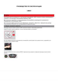
Краткое руководство по эксплуатации Mitsubishi i-MiEV.
- Автор: —
- Издательство: —
- Год издания: —
- Страниц: 6
- Формат: PDF
- Размер: 329 Kb


Introduction
N09200100934
Thank you for buying a Mitsubishi i-MiEV powered by MiEV
(Mitsubishi innovative Electric Vehicle) technology.
We are confident you will enjoy your vehicle. It has been engi-
neered for optimum performance, durability and comfort. By
thoroughly reading this Owner’s Manual, you will gain an
understanding of the many features that are included in the i-
MiEV. The Owner’s Manual contains descriptions and illustra-
tions that will assist in the operation and maintenance of your
vehicle.
A Certified i-MiEV Dealer will be happy to assist you with any
further questions you may have regarding the operation of your
vehicle.
Please note that this manual applies to all i-MiEV models and
explains all features including options. Some features
explained in this manual may not be installed on your vehicle.
Please leave this Owner’s Manual in the vehicle at the time of
resale. The next owner will appreciate having access to the
information contained here.
This manual includes instructions for standard and optional
equipment available at the time of printing. Mitsubishi Motors
Corporation reserves the right to make changes in design and
specifications and to make additions or improvements in its
product without assuming any obligation to install these on
previously manufactured products.
Throughout this manual the words WAR NING and CAUTION
appear.
These are reminders to be especially careful. Failure to follow the
instructions could result in personal injury or damage to your
vehicle.
WARN ING
!
Indicates a strong possibility of severe personal injury or
death if instructions are not followed.
CAUTION
!
Points out hazards or unsafe practices that could cause minor
personal injury or damage to your vehicle.
You will see another important symbol:
NOTE Gives helpful information.
WARN ING
!
●
Certain fluids contained in vehicles and certain
products of component wear contain or emit chemi-
cals known to the State of California to cause cancer
and birth defects or other reproductive harm.
©2011 Mitsubishi Motors Corporation Printed in Japan
12TQ-MiEV(NAS)_Cover2.fm 1 ページ 2011年7月26日 火曜日 午前7時47分