-
Contents
-
Table of Contents
-
Troubleshooting
-
Bookmarks
Quick Links
User Guide
MCTC-PES-E1
Programmable Electronic System
User Guide
A02
Data code 19010187
Related Manuals for Inovance Monarch MCTC-PEC-E1
Summary of Contents for Inovance Monarch MCTC-PEC-E1
-
Page 1
User Guide MCTC-PES-E1 Programmable Electronic System User Guide Data code 19010187… -
Page 2: Preface
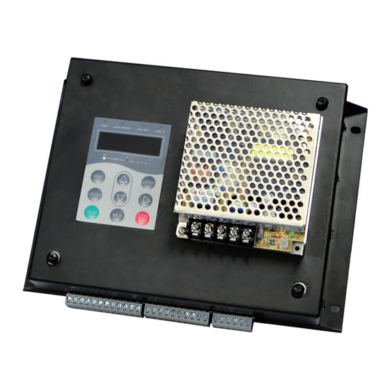
Preface Preface Thank you for purchasing the MCTC-PES-E1 system. MCTC-PES-E1, independently developed and produced by Suzhou Monarch Control Technology Co., Ltd., is a programmable electronic system in safety related applications for escalators and moving walkways (PESSRAE). The MCTC-PES-E1 adopts dual-CPU control and provides multiple security monitoring protections for escalators and moving walkways.
-
Page 3: Table Of Contents
Contents Contents Preface ……………………….1 Safety Instructions ……………………..4 Safety Disclaimer ……………………4 Safety Levels and Definitions ………………..4 ……………………4 Safety Instructions ……………………..8 Service life Chapter 1 Product Information ………………….9 1.1 Introduction ……………………..9 1.2 System Components ………………….9 1.3 System Functions ……………………10 1.3.1 Working States ………………….
-
Page 4
Contents 3.2 Basic Operations ……………………30 Chapter 4 Functional Parameters ………………..31 4.1 Parameter Description ………………….31 ………………..31 Group F0: Basic Parameters ………………..34 Group F1: State Parameters ………………..37 Group F2: Fault Information ………………..39 Group FF: Factory Parameters Group FP: Management Parameters ………………. -
Page 5: Safety Instructions
Safety Instructions Safety Instructions Safety Disclaimer 1) Read and comply with the safety instructions during installation, operation, and mainte- nance on the equipment. 2) To ensure the safety of humans and the products, follow the marks on the products and all the safety instructions in this document.
-
Page 6
Safety Instructions Storage and Transportation Caution ◆ Store this equipment based on the storage and transportation requirements on humidity and temperature. ◆ Avoid transporting the equipment in environment such as water splashing, rain, direct sun- light, high voltage, strong magnetic field, and strong vibration. ◆… -
Page 7
Safety Instructions Wiring Danger ◆ Do not allow non-professionals to perform product installation, wiring, maintenance, inspec- tion or parts replacement. ◆ Never perform wiring at power-on. Failure to comply may result in electric shock. ◆ Cut off all power supplies before wiring. Wait at least 10 minutes after power-off so that re- sidual voltage can discharge safely. -
Page 8
Safety Instructions Warning ◆ Prevent metal or other objects from falling into the device during operation, failure to com- ply may result in equipment damage. ◆ Never use contactors to start or stop the equipment. Failure to comply may result in dam- age to the equipment! Maintenance Danger… -
Page 9: Service Life
Safety Instructions Service life The service life of the MCTC-PES-E1 is 15 years. To ensure normal use and security, you need to replace the product that has been used for approximately 10 years (calculated from delivery) or return them to Monarch for repair and maintenance.
-
Page 10: Chapter 1 Product Information
Chapter 1 Product Information Chapter 1 Product Information 1.1 Introduction The MCTC-PES-E1 is designed to provide multiple security monitoring protections for escalators and moving walkways. It adopts dual-CPU control and judges the signals related to the escalator or moving walkway simultaneously. Once detecting a fault, the two CPUs instruct the safety relays to act and output the fault signal.
-
Page 11: System Functions
Chapter 1 Product Information Table 1-1Models of switching-mode power supply Component Quantity Adapted Model Remarks The switching- mode power Switching- ECU EPR-35-24 Schneider Mean Well supply of mode power EPR-35-24 ABL2REM24015H LRS-35-24 MCTC- supply (35W,DC24V) (35W,DC24V) (35W,DC24V) PES-E1 is provided by Monarch.
-
Page 12: Working States
Chapter 1 Product Information 1.3.1 Working States Table 1-3 States of the MCTC-PES-E1 State Description The system is powered on and then starts to run properly. In the startup Startup process, the system completes self-check and all relays are in the OFF state. You can modify parameters and reset faults using the external operation panel.
-
Page 13: Security Measures After Security Functions Enabled
Chapter 1 Product Information 1.3.3 Security Measures After Security Functions Enabled The following table describes the security measures after the security functions become enabled. Table 1-5 Security measures after the security functions enabled Power off Security Manual Description of Security Function the Supply of Circuit Open Reset…
-
Page 14: Chapter 2 Installation And Wiring
Chapter 2 Installation and Wiring Chapter 2 Installation and Wiring 2.1 Mechanical Installation 2.1.1 Installation environment requirements The MCTC-PES-E1 system is installed in the main control cabinet of the machine room of the escalator or moving walkway. Keep the installation room clean, well ventilated and dust &…
-
Page 15: Installation Instructions
Chapter 2 Installation and Wiring 201.0 101.0 88.0 RJ45 Φ6.0 Figure 2-2 Physical appearance of the control board (Unit:mm) 2.1.3 Installation Instructions To install the MCTC-PES-E1 system, do as follows: 1) Process the installation side in the main control cabinet. For the processing dimensions, refer to Figure 2-1.
-
Page 16
Chapter 2 Installation and Wiring Table 2-1 Technical data of Schneider sensors Brand Schneider Escalator/Moving Step loss detection Sensor Handrail speed sensor walkway speed sensor sensor XS2 18BLNAL2C XS2 12BLNAL2C XS2 30BLNAL2C Model XS2 18BLPAL2C XS2 12BLPAL2C XS2 30BLPAL2C Diameter 18mm 12mm 30mm… -
Page 17: Installing The Speed Sensor And Running Direction Sensor For Escalator/Moving Walkway
Chapter 2 Installation and Wiring Brand OMRON Brown (BN): Brown (BN): Brown (BN): positive Brown (BN): positive positive positive Definition of Blue (BU): Blue (BU): negative Blue (BU): negative Blue (BU): negative Cables negative Black (BK): output Black (BK): output Black (BK): output Black (BK): output signal…
-
Page 18: Installing The Handrail Speed Sensor
Chapter 2 Installation and Wiring 2 Detection Principle 1) Overspeed protection function By measuring the speed of the driving chain sprocket through sensor A and sensor B, MCTC-PES-E1 system judges whether the running speed of the escalator/moving walkway exceeds the allowable speed. If yes, MCTC-PES-E1 system will perform overspeed protection.
-
Page 19: Installing The Step/Pallet Loss Sensor
Chapter 2 Installation and Wiring 2 Detection Principle Sensor 3/4 is used to measure the left/right handrail speed. The tachometer wheel is driven by the handrail to rotate and its linear speed is basically consistent with the handrail speed. An inductive part is set on the tachometer wheel to mount sensor 3/4 on a fixed mechanical structure with the sensing face toward the inductive part.
-
Page 20
Chapter 2 Installation and Wiring Sensor Step Sensor 5/6 signal Figure 2-6 Installation position of the step/pallet loss sensor for escalator 2 Detection Principle Each sensor (5/6) is installed in the return/driving station in the top/bottom machine room, respectively to detect step loss. Based on signals of speed sensor A/B for the motor, the system calculates the number of pulses of sensor A/B between two adjacent pulses of sensor 5/6 to judge whether step/pallet loss occurs. -
Page 21
Chapter 2 Installation and Wiring Pallet Sensor Beam X Beam Y Sensor 5/6 signal Figure 2-7 Installation position of the step/pallet loss sensor for moving walkway ◆ The sensor must be installed within the sections where the bottom steps/ pallets moves horizontally, as shown in the following figure. The upper sensor must be installed between A and A’ and the lower sensor must be NOTE installed between B and B’. -
Page 22: Wiring
DC+/DC- supply switching-mode power complies with the supply. EN60950 standard. It communicates with Inovance NICE2000 Modbus integrated escalator The shielded twisted MOD+/MOD- communication controller. When a safety cable is suggested. fault occurs, the NICE2000…
-
Page 23
Chapter 2 Installation and Wiring Terminal Terminal Type Function Description Remark Symbol Name It is connected to the input terminal 24V of the control The switching- External +24 V system when X1 to X4 are mode power supply E24V power supply connected with corresponding complies with the signals of the control system in… -
Page 24
Chapter 2 Installation and Wiring Terminal Terminal Type Function Description Remark Symbol Name Escalator They are used for input of speed escalator speed detection pulses detection The MCTC-PES-E1 detects the phase A signal overspeed fault based on the frequency or cycle of two pulses, Escalator and detects the unintentional speed… -
Page 25
Chapter 2 Installation and Wiring Terminal Terminal Type Function Description Remark Symbol Name BIT0 It outputs the current fault code using the 8421 code and can BIT1 Fault binary be connected to the external code BIT2 A common relay is LED display. -
Page 26: Wiring Of The Mctc-Pes-E1
Chapter 2 Installation and Wiring 2.3.2 Wiring of the MCTC-PES-E1 The following figure shows wiring of the MCTC-PES-E1 system. Power supply to service brake 24V+ E24V 24V- X1 NO inspection sinal Insp. X2 NC inspection signal lnsp. up X3 System up signal Serivce brake Insp.
-
Page 27: Connecting The Floor Plate Switches
Chapter 2 Installation and Wiring The precautions on electrical wiring are as follows: 1) All input signals are low level active. 2) E24V is connected to the 24 V power supply of the escalator control system. DC+/DC- is connected to the switching-mode power supply of the MCTC-PES-E1. The X1 to X4 terminals are connected to the 24 V power supply of the escalator control system and cannot use the power supply of the MCTC-PES-E1.
-
Page 28: Connecting Brake Detection Switches In Dual-Motor Application
Chapter 2 Installation and Wiring As shown in Figure 2-10, the two switches in the top machine room must be connected to the two switches in the bottom machine room in series. The two signals are respectively connected to X10 and X11. Thus, if any floor plate is removed, both signals have a change. 2.3.4 Connecting Brake Detection Switches in Dual-Motor Application In the application of dual motors and dual brakes, to satisfy China’s GB standard, obey the following instructions:…
-
Page 29: Chapter 3 Operation Panel
Chapter 3 Operation Panel Chapter 3 Operation Panel 3.1 LED Operation Panel The MCTC-PES-E1 system has a keypad with an LED display. You can use the keypad to modify the parameters, monitor operation status and check fault information. See the following figure for details.
-
Page 30: Indicators
Chapter 3 Operation Panel Button Name Function Reserved Function Reserved MF.K Reserved Function Reserved QUICK 3.1.2 Indicators In the following table, indicates that the indicator is on; indicates that the indica- tor is off; indicates that the indicator blinks. Table3-1 Panel indicator description Indicator Status Description Frequency unit Hz…
-
Page 31: Basic Operations
Chapter 3 Operation Panel 3.2 Basic Operations The operation panel uses the 3-level menu structure for the operations such as parameter settings. 3-level menus: ■ Level-1: parameter group ■ Level-2: parameter ■ Level-3: parameter settings After entering a level of menu, if a bit blinks, you can press the , and buttons to set the parameter.
-
Page 32: Chapter 4 Functional Parameters
Chapter 4 Functional Parameters Chapter 4 Functional Parameters 4.1 Parameter Description The content in each column of the parameter table is described as follows: Parameter Name Setting Range Factory Setting Unit Operation Operation attribute Number Full name Valid range of Factory setting Unit of the of the functional…
-
Page 33
Chapter 4 Functional Parameters Parameter Name Setting Range Factory Setting Unit Operation Maximum braking- F0-04 0.20–1.69 ★ to-stop distance The upper limit and lower limit of this parameter are controlled by F0-01 (Nominal speed). If the system detects that the braking-to-stop distance exceeds 1.2 times of the setting of F0-04, the system reports the braking-to-stop over-distance fault. -
Page 34
Chapter 4 Functional Parameters Parameter Name Setting Range Factory Setting Unit Operation Auxiliary function F0-08 0–65535 ★ selection The auxiliary functions of the system are described in the following table. Table 4-2 Auxiliary functions indicated by bits of F0-08 Description 0: Escalator running not available when the auxiliary brake is applied 1: Escalator running available only in the upward direction when the auxiliary brake is applied… -
Page 35: Group F1: State Parameters
Chapter 4 Functional Parameters Group F1: State Parameters Parameter Name Setting Range Factory Setting Unit Operation Phase A escalator F1-00 ● speed Phase B escalator F1-01 ● speed They indicate the escalator speed respectively, detected by sensor A and sensor B. Parameter Name Setting Range…
-
Page 36
Chapter 4 Functional Parameters It indicates the detected braking-to-stop distance after stop. Parameter Name Setting Range Factory Setting Unit Operation Pulse time interval of F1-06 ● left handrail Pulse time interval of F1-07 ● right handrail They indicate the actually detected cycles of left and right handrail signals (no display during inspection). -
Page 37
Chapter 4 Functional Parameters If OP is shorted to DC+, input terminals X15 to X20 are low level active. If OP is shorted to DC-, X15 to X20 are high level active. The other input terminals are low level active and become ON when they are shorted to 0V. -
Page 38: Group F2: Fault Information
Chapter 4 Functional Parameters ◆ This parameter records only the faults that need manual reset. After the fault is reset manually, the fault record is cleared. NOTE Parameter Name Setting Range Factory Setting Unit Operation F1-18 Err Flag ● It indicates the faults that have occurred. Besides the faults that need manual reset, it records the faults that can be reset at power failure.
-
Page 39
Chapter 4 Functional Parameters F2-01 1st fault sub-code ● F2-02 2nd fault code ● F2-03 2nd fault Sub-code ● F2-04 3rd fault code ● F2-05 3rd fault sub-code ● F2-06 4th fault code ● F2-07 4th fault sub-code ● F2-08 Latest fault code ●… -
Page 40: Group Ff: Factory Parameters
Chapter 4 Functional Parameters Input state 2 at latest F2-20 ● fault Output state at latest F2-21 ● fault Phase A escalator F2-22 ● speed at latest fault Phase B escalator F2-23 ● speed at latest fault Detected running F2-24 direction at latest ●…
-
Page 41: Examples Of Commissioning Applications
Chapter 4 Functional Parameters 4.2 Examples of Commissioning Applications Here gives some commissioning application examples, in which the rated speed is set as the actual running speed. 1) Suppose that escalator is used in the application. The rated speed of the escalator is 0.5 m/s, the radius of the driving chain sprocket is 0.3 m and the number of teeth of the driving chain sprocket is 72.
-
Page 42
Chapter 4 Functional Parameters Set parameters in group F0 as follows: Parameter Name Setting Range Setting Handrail pulse time interval at F0-05 0.01–5.00 0.63 nominal speed Upper limit of phase A/B pulses for F0-06 step signals Lower limit of phase A/B pulses for F0-07 0 to F0-06 step signals… -
Page 43: Chapter 5 Troubleshooting
Chapter 5 Troubleshooting Chapter 5 Troubleshooting 5.1 Fault Description The MCTC-PES-E1 system provides a total of 16 pieces of fault information and protective functions. It monitors various input signals, running conditions and external feedback information in real time. After a fault occurs, the system implements the protection function, and displays the fault code.
-
Page 44
Chapter 5 Troubleshooting Fault Fault Name Description Code Floor plate Err11 The floor plate switch signal is active in normal state. switch fault 1: There are A/B pulses in the stop state. 2: There is no A/B pulse within 4s after startup. 3: The number of A/B pulses for up step signals is smaller than the setting of F0-07. -
Page 45: System Prompt Faults
Chapter 5 Troubleshooting 5.2 System Prompt Faults This section describes the system prompts and protection levels related to the faults occurring on the safety functions protected by the system. Table 5-2 System prompt for the faults of the MCTC-PES-E1 Fault Code Fault Name System Prompt Overspeed of 1.2 times…
-
Page 46: Revision History
Revision History Revision History Date Revision Change Description V0.0 First issue. 2013-11 ◆ Added Omron sensors and access cover switches. ◆ Added information on F0-08 Bit6, Bit7, Bit9, Bit10, and Bit11. 2018-04 ◆ Modified information on F1-04 and F1-18. ◆ Added safety information for step/pallet detection sensors.
-
Page 47: Warranty Agreement
Warranty Agreement Warranty Agreement 1) Inovance provides an 18-month free warranty to the equipment itself from the date of manufacturing for the failure or damage under normal use conditions. 2) Within the warranty period, maintenance will be charged for the damage caused by the following reasons: a.
-
Page 48
//www.inovance.com Shenzhen Inovance Technology Co., Ltd. Add.: Building E, Hongwei Industry Park, Liuxian Road, Baocheng No. 70 Zone, Bao’an District, Shenzhen Tel: +86-755-2979 9595 Fax: +86-755-2961 9897 Service Hotline: 400-777-1260 http: //www.inovance.com Copyright Shenzhen Inovance Technology Co., Ltd.
Chapter 1 Product Information
Table 1-1Models of switching-mode power supply
Component Quantity
Switching-
mode power
supply
Table 1-2 Models of sensors and detection switches
Accessory
Escalator/Moving
walkway speed
sensor
Handrail speed
sensor
Step loss
detection sensor
Detection Switch
Motor brake
detection switch
Auxiliary brake
detection switch
Floor plate
detection switch
The MCTC-PES-E1 is designed to ensure safe running of escalator and moving walkway
according to the security grading defined in the newest escalator security standard
GB16899-2011. It has the following security functions:
■ Overspeed protection
■ Unintentional reversal protection
■ Handrail speed deviation protection
■ Service brake and auxiliary brake monitoring protection
■ Step or pallet loss protection
■ Braking-to-stop distance detection and alarm
■ Floor plate state monitoring
—
—
10
ECU EPR-35-24
1
EPR-35-24
(35W,DC24V)
Quantity
Sensor
Schneider
2
XS2 18BLNAL2C
2
XS2 12BLNAL2C
2
XS2 30BLNAL2C
Schmersal
TS236-02Z
2
TS236-11Z
TS236-02Z
1
TS236-11Z
TS236-02Z
4
TS236-11Z
Adapted Model
Schneider
ABL2REM24015H
(35W,DC24V)
Recommended Model
OMRON
E2B-M18KN16-WP-C1-
MNK
E2B-M12KN08-WP-C1-
MNK
E2B-M30KN20-WP-C1-
MNK、E2B-M30LN30-
WP-C1-MNK
OMRON
D4N-4132
D4NA-4131
D4N-4132
D4N-4132
D4N-2B64-E1
D4NA-412G
Remarks
The switching-
mode power
Mean Well
supply of
LRS-35-24
MCTC-
(35W,DC24V)
PES-E1 is
provided by
Monarch.
Remarks
Specify the required
sensor models in
your order. Monarch
will deliver them
(except NBN40-L2-
E0-V1) together with
the MCTC-PES-E1.
Both low-level and
high-level signals
are supported.
Customer option
MCTC-PES-E1 PESSRAE User Manual
Preface
Preface
Thank you for purchasing the MCTC-PES-E1 system.
MCTC-PES-E1, independently developed and produced by Suzhou Monarch Control
Technology Co., Ltd., is a programmable electronic system in safety related applications for
escalators and moving walkways (PESSRAE).
The MCTC-PES-E1 adopts dual-CPU control and provides multiple security monitoring
protections for escalators and moving walkways. The system satisfies the GB/16899-2011
Safety Rules for the Construction and Installation of Escalators and Moving Walks.
This manual describes the correct use of the MCTC-PES-E1 system. System installation,
commissioning and maintenance must be performed only by qualified personnel with related
experience.
It introduces the construction, features, security prompts, design & installation, operation &
maintenance, and faults & solutions of the MCTC-PES-E1 system. Read and understand
the manual before use, and keep it properly for future reference.
Notes
• The drawings in the manual are sometimes shown without covers or protective guards.
Remember to install the covers or protective guards as specified first, and then perform
operations in accordance with the instructions.
• The drawings in the manual are shown for description only and may not match the product
you purchased.
• The instructions are subject to change, without notice, due to product upgrade, specification
modification as well as efforts to increase the accuracy and convenience of the manual.
• Contact our agents or customer service center if you have some questions during the use.
-1-
Contents
Preface ...................................................................................................................1
Chapter 1 Safety Information and Precautions.......................................................4
1.1 Safety Precautions����������������������������������������������������������������������������������������������������������� 4
1.2 General Precautions��������������������������������������������������������������������������������������������������������� 5
Chapter 2 Product Information ...............................................................................8
2.1 Introduction����������������������������������������������������������������������������������������������������������������������� 8
2.2 System Components and Functions�������������������������������������������������������������������������������� 8
Chapter 3 Mechanical and Electrical Installation ..................................................14
3.1 Mechanical Installation��������������������������������������������������������������������������������������������������� 14
3.2 Installation of Sensors���������������������������������������������������������������������������������������������������� 16
3.3 Electrical Installation������������������������������������������������������������������������������������������������������� 22
Chapter 4 System Operation and Commissioning ...............................................30
4.1 Operation Panel������������������������������������������������������������������������������������������������������������� 30
4.2 Viewing and Modifying Function Codes������������������������������������������������������������������������� 31
4.3 Function Code Description and Applications������������������������������������������������������������������ 32
Group F0: Basic Parameters������������������������������������������������������������������������������������������������ 32
Group F1: State Parameters������������������������������������������������������������������������������������������������ 35
Group F2: Fault Information������������������������������������������������������������������������������������������������� 38
Group FF: Factory Parameters�������������������������������������������������������������������������������������������� 39
Group FP: Management Parameters����������������������������������������������������������������������������������� 39
4.4 Examples of Commissioning Applications���������������������������������������������������������������������� 39
Chapter 5 Troubleshooting ...................................................................................42
1
Safety Information and Precautions
Safety Information and Precautions
MCTC-PES-E1 PESSRAE User Manual
Chapter 1 Safety Information and Precautions
1.1 Safety Precautions
Use Stage
Safety
Grade
Precautions
• Do not install the equipment if you find water seepage,
component missing or damage upon unpacking.
DANGER
During
installation
• Do not install the equipment if the packing list does not conform
to the product you received.
• Install the equipment on incombustible objects such as metal,
and keep it away from combustible materials. Failure to comply
may result in a fire.
• Do not loosen the fixed screws of the components.
• Handle the equipment with care during transportation to prevent
damage to the equipment.
WARNING
• Do not use the equipment with damaged or missing components.
Failure to comply will result in personal injury.
• Do not touch the components with your hands. Failure to comply will
result in static electricity damage.
• Install the equipment in places free of vibration and direct sunlight.
• Wiring must be performed only by qualified personnel under
instructions described in this manual. Failure to comply may
result in unexpected accidents.
DANGER
At wiring
WARNING
• Ensure that the power supply is cut off before wiring. Failure to
comply may result in electric shock.
• Before wiring, cut off the power supply of the escalator or
moving walkway using reliable insulation device. Do not
guarantee safety of engineers by depending on the stop, startup
or input signal of the equipment because these signals cannot
insulate hazardous voltage.
• Pay attention to the marks of the wiring terminals and ensure
correct wiring. Failure to comply will result in damage to the
controller.
• Use a shielded twisted pair (STP) cable with twist pitch of 20−30
mm for communication, and ensure that the shield is reliably
grounded.
-4-
MCTC-PES-E1 PESSRAE User Manual
Use Stage
Safety Information and Precautions
Safety
Grade
Precautions
• Perform wiring of all peripheral devices under the instructions
of the manual and ensure correct wiring according to the circuit
diagram in the manual. Failure to comply will result in accidents.
DANGER
During
operation
• Do not touch the system or surrounding circuits. Failure to comply
will result in electric shock.
• Do not touch any I/O terminal of the system. Failure to comply may
result in electric shock.
• Non-qualified personnel are prohibited to perform signal detection
during operation. Failure to comply may result in personal injury or
damage to the equipment.
• The equipment has high voltage input. The hazardous voltage may
result in severe electric shock or even death. Please keep cautious
DANGER
when you use or get close to the system that has been connected
to the power supply.
WARNING
• Ensure correct wiring of input and output terminals before
use for the first time, check whether short circuit exists in the
peripheral circuits connected to the MCTC-PES-E1, and check
whether the wiring is secure. Failure to comply will result in
damage to the MCTC-PES-E1.
• Do not change the default settings of the MCTC-PES-E1.
Failure to comply may result in damage to the system.
• Do not repair or maintain the MCTC-PES-E1 at power-on.
Failure to comply will result in electric shock.
During
maintenance
• Repair or maintenance of the MCTC-PES-E1 may be performed
only by qualified personnel. Failure to comply will result in
personal injury or damage to the equipment.
DANGER
• Set and check the parameters again after the MCTC-PES-E1 is
replaced.
• All the pluggable components must be plugged or removed only
after power-off.
1.2 General Precautions
1)
Service life
The service life of the MCTC-PES-E1 is 15 years. To ensure normal use and security, you
need to replace the product that has been used for approximately 10 years (calculated from
delivery) or return them to Monarch for repair and maintenance.
2)
Statement on selection of parts
The power supply switches and sensors required by the MCTC-PES-E1 system have been
certified by related institutions and must be selected according to the listed models in the
manual. Monarch will assume no risk or responsibility if you use the models that are not
recommended in the manual.
-5-
Safety Information and Precautions
3)
MCTC-PES-E1 PESSRAE User Manual
Installation environment requirements
The MCTC-PES-E1 system is installed in the machine room of the escalator or moving
walkway. The installation environment must satisfy the requirements described in Table 1-2.
Monarch will assume no risk or responsibility if a fault occurs in the system because the
installation environment requirements are not satisfied.
Table 1-2 Installation environment requirements
Item
Requirements
Ambient temperature
-20°C to +65°C
Humidity
Less than 95% RH, without condensing
Mounting location
Free from conducting materials, corrosive gas, combustible gas,
metal powder, oil dirt and dust
IP00 (no IP level requirement on board)
IP level
IP5X (with housing)
Note: The MCTC-PES-E1 system has the housing that satisfies IP5X.
If you purchase the board only, install the board in the control cabinet
or other housing satisfying IP5X.
-6-
2
Product Information
Product Information
MCTC-PES-E1 PESSRAE User Manual
Chapter 2 Product Information
2.1 Introduction
The MCTC-PES-E1 is designed to provide multiple security monitoring protections for
escalators and moving walkways. It adopts dual-CPU control and judges the signals related
to the escalator or moving walkway simultaneously. Once detecting a fault, the two CPUs
instruct the safety relays to act and output the fault signal.
Furthermore, the two CPUs monitor each other. If one CPU breaks down or is damaged,
the other instructs the safety circuits to act immediately and output the corresponding
fault signal. The MCTC-PES-E1 has an LED operation panel, on which you can perform
operations such as parameter modification and working status monitoring.
The following figure shows the physical appearance of the MCTC-PES-E1.
Figure 2-1 Physical appearance of the MCTC-PES-E1 (a control board fixed inside the black
housing)
2.2 System Components and Functions
2.2.1 System Configuration
The MCTC-PES-E1 is configured with a control board, a protective guard, and a switchingmode power supply (the models are introduced in Table 2-1).
Table 2-1Models of switching-mode power supply
Component Quantity
Switchingmode power
supply
Adapted Model
The switchingmode power
ECU EPR-35-24
supply of
ABL2REM24015H NES-35-24
(35 W, 24 VDC)
MCTC-PES-E1
(35 W, 24 VDC)
(35 W, 24 VDC) is provided by
Monarch.
Schneider
1
Remarks
-8-
Mean Well
MCTC-PES-E1 PESSRAE User Manual
Product Information
Note
The switching-mode power supply provides power supply only to the components of the MCTCPES-E1 (including the control board and the connected sensors and detection switches). It is
prohibited to provide power supply to any other devices.
When installing the MCTC-PES-E1, six sensors and seven detection switches are required.
The sensor models are designated and sold by Monarch, while the detection switches are
decided by the customer. The recommended models of the sensors and detection switches
are introduced in Table 2-2.
Monarch will assume no risk or responsibility if the customer uses the models that are not
recommended in the manual.
Table 2-2 Models of sensors and detection switches
Accessory
Quantity
Recommended Model
Sensor
Schneider
Escalator/Moving
walkway speed
sensor
2
Handrail speed
sensor
2
Step loss
detection sensor
2
Specify the required
sensor models in
your order. Monarch
will deliver them
XS2 12BLNAL2C NBN4-12GM50-E0-MO (except NBN40-L2E0-V1) together with
NBN15-30GM50-E0-MO the MCTC-PES-E1.
XS2 30BLNAL2C
NBN40-L2-E0-V1
XS2 18BLNAL2C NBN8-18GM50-E0-MO
Detection Switch
Schmersal
Motor brake
detection switch
2
Auxiliary brake
detection switch
1
Floor plate
detection switch
4
Remarks
P+F
OMRON
TS236-02Z
D4N-4132
TS236-11Z
D4NA-4131
TS236-02Z
TS236-11Z
D4N-4132
TS236-02Z
D4N-4132
TS236-11Z
D4N-2B64-E1
Customer option
2.2.2 System Functions
The MCTC-PES-E1 is designed to ensure safe running of escalator and moving walkway
according to the security grading defined in the newest escalator security standard
GB16899-2011. It has the following security functions:
1)
Overspeed protection
2)
Unintentional reversal protection
3)
Handrail speed deviation protection
4)
Service brake and auxiliary brake monitoring protection
5)
Step or pallet loss protection
6)
Braking-to-stop distance detection and alarm
7)
Floor plate state monitoring
-9-
Product Information
MCTC-PES-E1 PESSRAE User Manual
■■ Working States
The following table describes the states of the MCTC-PES-E1.
Table 2-3 States of the MCTC-PES-E1
State
Description
Startup
The system is powered on and then starts to run properly. In the startup
process, the system completes self-check and all relays are in the OFF state.
Setting
You can modify parameters and reset faults using the external operation panel.
This mode is active only when the system is in the stop state. When the system
is running, you can change nothing using the operation panel.
Stop
The system is not powered on and all relays are in the OFF state.
Fault
The system itself has abnormality, such as self-check failure. In such state, all
relays are cut off. You need to power on the system again.
Normal
All functions are normal during running.
Inspection
The system enters the inspection state after the inspection signal becomes
active. In such state, the step loss detection function, motor braking detection
function and handrail speed detection function are disabled, while the other
functions are available.
Manual
reset
The system enters the manual reset state after the manual reset signal
becomes active. In such state, all securitiy functions are disabled and all relay
outputs are in the OFF state.
■■ Description of Security Functions
The following table describes the security functions provided by the MCTC-PES-E1.
Table 2-4 Description of security functions
No.
Security Function
Description
1
Over-speed protection 1
Check the speed and acts before the speed exceeds
1.2 times of nominal speed.
2
Over-speed protection 2
Check the speed and act before the speed exceeds
1.4 times of nominal speed.
3
Unintentional reversal
protection
Check the unintentional reversal running.
4
Brake monitoring protection
Check the action of the auxiliary brake.
5
Step or pallet loss protection
Check whether the step or pallet is lost.
6
Brake monitoring protection
Check whether the main brake is released.
7
Handrail speed deviation
protection
Check the deviation between the handrail speed and
the actual step or pallet speed. If the speed deviation
is greater than -15% and continues for 15s, the system
performs protection.
8
Braking-to-stop distance
detection and alarm
Check the braking-to-stop distance. If the distance
exceeds 1.2 times of the allowable maximum value,
the system performs protection.
9
Floor plate detection switch
Check whether the floor plate is opened or removed.
- 10 -
MCTC-PES-E1 PESSRAE User Manual
Product Information
■■ Security Measures After Security Functions Enabled
The following table describes the security measures after the security functions become
enabled.
Table 2-5 Security measures after the security functions enabled
No.
Description of Security Function
Security
Circuit Open
Power off
the Supply of
Auxiliary Brake
Manual
Reset
1
Check the speed and acts before the speed
exceeds 1.2 times of nominal speed.
Yes
No
Yes
2
Check the speed and acts before the speed
exceeds 1.4 times of nominal speed.
Yes
Yes
Yes
3
Check the unintentional reversal running.
Yes
Yes
Yes
4
Check the action of the auxiliary brake.
Yes
No
No
5
Check whether the step or pallet is lost.
Yes
No
Yes
6
Check whether the main brake is released.
Yes
No
Yes
7
Check the deviation between the handrail
speed and the actual step or pallet speed.
If the speed deviation is greater than -15%
and the duration exceeds 15s, it performs
protection.
Yes
No
No
8
Check the braking-to-stop distance. If the
distance exceeds 1.2 times of the allowable
maximum value, it performs protection.
Yes
No
Yes
9
Check whether the floor plate is opened/
removed.
Yes (see
the "Note"
below.)
No
No
Note
The security circuit of the escalator or moving walkway is cut off after the floor plate is opened or
removed. After the system enters the inspection state, the fault is reset automatically.
- 11 -
Product Information
MCTC-PES-E1 PESSRAE User Manual
- 12 -
3
Mechanical and Electrical Installation
Mechanical and Electrical Installation
MCTC-PES-E1 PESSRAE User Manual
Chapter 3 Mechanical and Electrical Installation
3.1 Mechanical Installation
3.1.1 Installation Dimensions
The following figure shows the dimensions of the MCTC-PES-E1 system.
Figure 3-1 Dimensions of the MCTC-PES-E1 system
Unit: mm
Switching-mode
power supply
187.0
150.0
MCTC-PES-E1
4-5.5
4-8.0
245.0
42.8
260.0
78.8
Only the control board (without the protective guard) is required in some applications. The
following figures show the physical appearance and installation dimensions of the control
board.
Figure 3-2 Physical appearance of the control board
Figure 3-3 Installation dimensions of the control board
- 14 -
MCTC-PES-E1 PESSRAE User Manual
Mechanical and Electrical Installation
201.0
7.0
101.0
CN1
RJ45
178.0
148.0
CN5
162.0
6.0
88.0
CN3
CN4
J3
Unit: mm
Φ6.0
3.1.2 Installation Method and Precautions
To install the MCTC-PES-E1 system, do as follows:
1. Process the installation side in the main control cabinet. For the processing dimensions,
refer to Figure 3-1.
2. Mount the MCTC-PES-E1 on the installation side and fix it with screws.
If only the control board (without the protective guard) is required, do as follows:
1. Process the installation side in the main control cabinet. For the processing dimensions,
refer to Figure 3-3.
2. Mount the control board on the installation side and fix it with screws.
Observe the following precautions during installation:
1)
The switching-mode power supply has been fixed on the protective guard of the MCTCPES-E1 system upon delivery.
2)
The screws for fixing the protective guard are not delivered together with the MCTCPES-E1 and you need to prepare them yourself. When selecting screws, consider the
plate thickness of the installation side, the thickness of the protective guard and the
dimension of the hole in Figure 3-1.
3)
The MCTC-PES-E1 system is installed in the main control cabinet of the machine room
of the escalator or moving walkway. Keep the installation room clean, well ventilated
and dust & moisture proofing. Especially when only the control board without the
protective guard is installed, take other dust & moisture proofing measures.
- 15 -
Mechanical and Electrical Installation
MCTC-PES-E1 PESSRAE User Manual
3.2 Installation of Sensors
3.2.1 Technical Data of Sensors
The following table describes the technical data of the sensors.
Table 3-1 Technical data of Schneider sensors
Brand
Schneider
Sensor
Escalator/Moving
walkway speed sensor
Handrail speed sensor
Step loss detection
sensor
Model
XS2 18BLNAL2C
XS2 12BLNAL2C
XS2 30BLNAL2C
Diameter
18 mm
12 mm
30 mm
Sensing
Distance
≤ 8 mm
≤ 4 mm
≤ 15 mm
Length
50.6 mm
41.3 mm
50.6 mm
Power
Supply (DC)
12–24 V
12–24 V
12–24 V
Output
NPN
NPN
NPN
Brown (BN): positive
Brown (BN): positive
Blue (BU): negative
Blue (BU): negative
Black (BK): output signal
Black (BK): output signal
Black (BK): output
signal
a = 50.6 mm
a = 50.6 mm
a = 50.6 mm
b = 40.4 mm
b = 34.1 mm
b = 35.4 mm
Definition of
Cables
Brown (BN): positive
Blue (BU): negative
Appearance
Dimension
b
a
- 16 -
MCTC-PES-E1 PESSRAE User Manual
Mechanical and Electrical Installation
Table 3-2 Technical data of the P+F sensors
Brand
P+F
Sensor
Escalator/
Handrail speed
Moving walkway
Step loss detection sensor
sensor
speed sensor
Model
NBN8-18GM50E0-MO
NBN4-12GM50- NBN15E0-MO
30GM50-E0-MO
NBN40-L2-E0-V1
Diameter
18 mm
12 mm
30 mm
Square (see the
dimension)
Sensing
Distance
≤ 8 mm
≤ 4 mm
≤ 15 mm
≤ 40 mm
Length
50 mm
50 mm
50 mm
See the dimension.
Power
10–30 V
Supply (DC)
10–30 V
10–30 V
10–30 V
Output
NPN
NPN
NPN
NPN
Brown (BN):
positive
Brown (BN):
positive
Brown (BN):
positive
Brown (BN): positive
Blue (BU):
negative
Blue (BU):
negative
Blue (BU):
negative
Black (BK): output signal
Black (BK):
output signal
Black (BK):
output signal
Black (BK):
output signal
Definition of
Cables
Blue (BU): negative
Do not connect the white
cable.
Appearance
M12 x 1
LED
36
LED
20
50
5
47
50
17
24
30
40
18
40
4
47
50
4
Dimension
M30 x 1.5
5
10
M18 x 1
LED
46
5.5
60
Φ5.5
Note
• All the sensor models except NBN40-L2-E0-V1 are obtainable in Monarch.
• The principle on selecting step or pallet loss sensor is as follow:
––
For iron step or pallet, select XS2 30BLNAL2C or NBN15-30GM50-E0-MO.
––
For aluminum step or pallet, it is suggested to select NBN40-L2-E0-V1 (P+F), whose
detection distance is long and signal is reliable.
- 17 -
Mechanical and Electrical Installation
MCTC-PES-E1 PESSRAE User Manual
3.2.2 Installing the Speed Sensor and Running Direction Sensor for Escalator/Moving
Walkway
■■ Installation
1)
Align the center of the sensing face of one sensor with the center of one tooth on the
driving chain sprocket and align the sensing edge of the other sensor with the center of
the neighboring tooth on the driving chain sprocket, as shown in the following figure.
2)
Installation distance 3 mm ≤ LA = LB ≤ 8 mm
The following figure shows the installation of the escalator/moving walkway speed sensor
and running direction sensor.
Figure 3-4 Installation of the escalator/moving walkway speed sensor and running direction
sensor
R
Speed measured
by the driving chain
sprocket
LB
Sensor B
Sensor A
LA
Sensor A signal
Sensor B signal
■■ Detection Principle
1)
Overspeed protection function
By measuring the speed of the driving chain sprocket through sensor A and sensor B,
the MCTC-PES-E1 system judges whether the running speed of the escalator/moving
walkway exceeds the allowable speed. If yes, the MCTC-PES-E1 system will perform
overspeed protection.
When the driving chain sprocket rotates, every time a sensor detects a tooth, the
sensor sends a pulse. The MCTC-PES-E1 system calculates the running speed of the
escalator/moving walkway based on the time interval of detected pulses.
Sensor A and sensor B are redundant speed measuring channels for each other. By
setting a certain pulse cycle or frequency threshold, 1.2 times or 1.4 times overspeed
can be detected.
2)
Unintentional reversal protection
By fixing the relative positions of the two sensors correctly, make the phase of sensor A
in advance of the phase of sensor B and ensure that the two sensors have overlapping
pulse part. In this case, the MCTC-PES-E1 system detects the logic sequence of the
two sensors and judges the actual running direction of the escalator/moving walkway
through the logic sequence, preventing reversal running.
- 18 -
MCTC-PES-E1 PESSRAE User Manual
Mechanical and Electrical Installation
3.2.3 Installing the Handrail Speed Sensor
■■ Installation
1)
Align the sensor with the inductive part on the tachometer wheel.
If the tachometer wheel is made of plastic, use a ferric device as the inductive part.
If the tachometer wheel is ferric, drill a hole as the inductive part in the wheel. The
section size of the inductive part should be approximate to that of the sensing face of
the sensor.
2)
Installation distance: 1 mm ≤ L3 = L4 ≤ 4 mm
The following figure shows the installation position of the handrail speed sensor.
Figure 3-5 Installation position of the handrail speed sensor
Tachometer
wheel
Inductive part
Sensor 3/4
Handrail
L3/4
Sensor 3/4
Sensor 3/4 signal
■■ Detection Principle
Sensor 3/4 is used to measure the left/right handrail speed. The tachometer wheel is driven
by the handrail to rotate and its linear speed is basically consistent with the handrail speed.
An inductive part is set on the tachometer wheel to mount sensor 3/4 on a fixed mechanical
structure with the sensing face toward the inductive part.
When the tachometer wheel follows the handrail to rotate, sensor 3/4 outputs pulses, as
shown in Figure 3-5. A pulse is output every time the tachometer wheel rotates a revolution.
With the pulses and radius of the wheel, the system can measure the rotational speed of
the tachometer wheel. Then the system calculates the handrail speed and compares it
with the escalator/moving walkway speed. If the handrail speed is lower than 85% of the
corresponding escalator/moving walkway speed and the handrail underspeed continues
for 15s, the system cuts off the power supply to the safety circuit of the escalator/moving
walkway to stop the running, implementing protection.
- 19 -
Mechanical and Electrical Installation
MCTC-PES-E1 PESSRAE User Manual
3.2.4 Installing the Step/Pallet Loss Sensor
1)
Installation
For aluminum step or pallet, it is suggested to select NBN40-L2-E0-V1 (P+F), whose
detection distance is long and signal is reliable. Each step/pallet loss sensor is required
for the top and bottom machine rooms respectively. Install the sensor with the sensing
face toward the step beam to be detected.
2)
Installation distance: 5 mm ≤ L5 = L6 ≤ 15 mm
The following figure shows the installation position of sensor (5/6) for the escalator.
Figure 3-6 Installation position of the step/pallet loss sensor for escalator
Step
L5/L6
Step beam to
be detected
Sensor
Sensor 5/6 signal
3)
Step
5/6
L5/L6
Step/Pallet loss
sensor 5/6
Detection Principle
Each sensor (5/6) is installed in the return/driving station in the top/bottom machine
room, respectively to detect step loss. Based on signals of speed sensor A/B for the
motor, the system calculates the number of pulses of sensor A/B between two adjacent
pulses of sensor 5/6 to judge whether step/pallet loss occurs.
When a step passes, sensor 5/6 receives the signal and outputs a pulse. Set the time
interval between two adjacent pulses of sensor 5/6 as T and the pulse counting of
sensor A/B within T as X. In the case of no step loss, the X value is within a certain
threshold regardless of the escalator speed. If X exceeds the threshold, the system
judges that step loss occurs. Then the escalator stops running immediately and enters
the safety state.
- 20 -
MCTC-PES-E1 PESSRAE User Manual
Mechanical and Electrical Installation
Note
If the detection principle is not suitable to the use habit of escalator manufacturers, step loss
can be monitored by using sensor 5/6 to detect the step auxiliary wheel. The prerequisite is
to ensure that the auxiliary wheel is lost while the step gets lost in any way.
To detect whether a pallet of the moving walkway is lost, install sensor 5/6 in the
machine room, as shown in the following figure.
Figure 3-7 Installation position of the step/pallet loss sensor for moving walkway
Pallet
Sensor
5/6
Beam X
Beam Y
Sensor 5/6 signal
WARNING
Besides the MCTC-PES-E1 and the six sensors, you need to prepare the following two devices:
• Relay at front end of signal X1 on the MCTC-PES-E1 board
• Switch for manual fault reset
- 21 -
Mechanical and Electrical Installation
MCTC-PES-E1 PESSRAE User Manual
3.3 Electrical Installation
3.3.1 Description of System Terminals
The following figure shows the layout of the system terminals.
Figure 3-8 Layout of the system terminals
M4
Y4
M3
Y3
Reserved
Reserved
M2
Y2
M1
Y1
BM
BM
BIT4
BIT2
BIT1
BIT0
CN5
CN4
MCTC-PES-E1
control board
CN2
CN3
X20
OP
DC+
MOD+
MODDC-
E24V
X1
X2
X3
X4
Reserved
X5
X6
X7
X8
X9
X10
CN1
X11
Reserved
Reserved
X14
Reserved
X15
X16
X17
X18
X19
J11
The following table describes the terminals of the MCTC-PES-E1.
Table 3-3 Description of terminals of the MCTC-PES-E1
Power/Communication
terminal (CN3)
Type
Terminal
Symbol
Terminal Name
DC+/DC-
24 V power
supply
The + 24 VDC power is
provided by specialized
switching-mode power
supply.
The switchingmode power supply
complies with the
EN60950 standard.
Modbus
communication
It communicates with
Inovance NICE2000
integrated escalator
controller. When a safety
fault occurs, the NICE2000
displays the fault code.
The shielded twisted
cable is suggested.
MOD+/MOD-
Function Description
- 22 -
Remark
MCTC-PES-E1 PESSRAE User Manual
Digital input terminal (CN1/2)
Type
Terminal
Symbol
Mechanical and Electrical Installation
Terminal Name
Function Description
E24V
External +24 V
power supply
It is connected to the input
terminal 24V of the control
system when X1 to X4 are
connected with corresponding
signals of the control system in
parallel.
X1
Normally open
(NO) inspection
signal
X2
Normally
closed (NC)
inspection
signal
X3
Up signal
It receives the up signal of the
control system and is edgetriggered.
X4
Down signal
It receives the down signal of
the control system and is edgetriggered.
X5
Service brake
signal
It is connected to the auxiliary
contact of the service brake.
X6
Service
brake action
detection 1
It is connected to the action
switch of the service brake.
X7
Service
brake action
detection 2
It is used in the dual-motor
application. It is shorted with X6
in the single-motor application.
X8
Auxiliary brake
signal
It is connected to the auxiliary
contact of the auxiliary brake.
X9
Auxiliary
brake action
detection
It is connected to the action
switch of the auxiliary brake.
X10
Floor plate
switch 1
It is connected to the floor plate
switch. This signal must be
active during normal running
and can be inactive during
inspection.
X11
Floor plate
switch 2
It has the same function as the
X10.
X12
Reserved
X13
Reserved
Manual reset
signal
The switchingmode power supply
complies with the
EN60950 standard.
They are connected to
the inspection signal input
terminals of the control system.
When X1/ X2 becomes ON, the
related functions of the MCTCPES-E1 are disabled according
to GB standard.
It is used for manual fault reset.
X14
Remark
The input becomes active after
the terminal keeps ON for more
than 2s and then keeps OFF
for more than 2s.
- 23 -
1) Optical coupling
isolation, low level
input active
2) Input impedance:
3.3 kΩ
3) Input voltage
range: 0–30 V
Mechanical and Electrical Installation
Digital input terminal (CN1/2)
Type
Terminal
Symbol
Terminal Name
Function Description
X15
Escalator
speed
detection
phase A signal
X16
Escalator
speed
detection
phase B signal
They are used for input of
escalator speed detection pulses
The MCTC-PES-E1 detects the
overspeed fault based on the
frequency or cycle of two pulses,
and detects the unintentional
reversal fault based on the pulse
phase.
X17
Up step loss
detection
It detects the A/B pulses. If the
pulse counting exceeds the
threshold, the MCTC-PES-E1
judges that it is step loss.
X18
Down step loss
detection
It uses the same detection mode
as X17.
X19
Left handrail
speed
detection
X20
Right handrail
speed
detection
If the MCTC-PES-E1 detects
that the handrail speed is 15%
lower than the actual speed of
the step, pallet or step chain
and the duration exceeds 15s, it
reports the handrail underspeed
fault.
OP
X15 to X20
polarity
selection
Y1/M1
Relay output terminal (CN4)
MCTC-PES-E1 PESSRAE User Manual
Fault output
When X15 to X20 are connected
to sensors of low level active,
OP is shorted to DC+. When
X15 to X20 are connected to
sensors of high level active, OP
is shorted to DC-.
It becomes OFF when a fault
occurs. It is connected to the
system safety circuit with Y1/M1.
Y3/M3
It becomes OFF when 1.4 times
overspeed or unintentional
reversal running occurs. It is
connected with Y4/M4 to control
the auxiliary brake.
Y4/M4
1) Optical coupling
isolation, low level
input active
2) Input impedance:
3.3 kΩ
3) Input voltage
range: 0–30 V
Shorting OP and
DC+/DC- is effective
for X15 to X20 only.
It becomes OFF when a fault
occurs. It is connected to the
system safety circuit with Y2/M2.
Y2/M2
Aulixiary brake
output
Remark
It becomes OFF when 1.4 times
overspeed or unintentional
reversal running occurs. It is
connected with Y3/M3 to control
the auxiliary brake.
- 24 -
Rated voltage: 250
VAC
Rated current: 6 A
MCTC-PES-E1 PESSRAE User Manual
Interface for
operation
panel (J11)
Power/
Communication
terminal (CN3)
Type
Terminal
Symbol
Terminal Name
BIT0
BIT1
BIT2
Fault binary
code
BIT3
BM
RJ45
Mechanical and Electrical Installation
Function Description
It outputs the current fault code
using the 8421 code and can
be connected to the external
LED display.
Common
terminal
It supports both common anode
LED display and common
cathode LED display.
Interface for
the operation
panel
It is connected to the operation
panel for modify ing parameters
or viewing the status.
Remark
A common relay is
used.
-
Note
• If there is no auxiliary brake in the system, short X8 and X9 to DC-.
• If the floor plate switches in the system have the compulsory break-off function, the related
function of this system can be disabled. In this case, short X10 and X11 to DC-.
3.3.3 Wiring of the MCTC-PES-E1
The following figure shows wiring of the MCTC-PES-E1 system.
- 25 -
Mechanical and Electrical Installation
MCTC-PES-E1 PESSRAE User Manual
Figure 3-9 Wiring of the MCTC-PES-E1 system
24V+
X1 NO inspection sinal
Insp.
X2 NC inspection signal
Insp. up
X3 System up signal
X4 System down signal
Top MC
X8 Auxiliary brake signal
X9 Auxiliary brake detection
X10 Floor plate switch 1
Top MC
Bottom MC
Switch 1
Switch 2
0V
0V
Auxiliary brake
X7 Service brake detection2
Switch 2
Bottom
MC
Chain
wheel
Switch 1
X6 Service brake detection1
1
2
3
X5 Service brake signal
Motor
4
Insp. down
COM
COM
Output of fault display (8421 code)
E24V
24V-
MCTC-PES-E1
Serivce brake
Control system for
escalator
Contactor
Power supply to service brake
X11 Floor plate switch 2
0V
Reserved
Manual reset switch
Contactor
X14 Manual reset signal
Reserved
Y1
X15 Escalator speed detection phase A
M1
X16 Escalator speed detection phase B
Y2
X17 Up step loss detection
M2
X18 Down step loss detection
Reserved
X19 Left handrail speed detection
Reserved
Y1/M1/Y2/M2 connected to the
safety circuit in series
Reserved
Y3
DC+
detection
Y3/M3/Y4/M4 M3
controlling the
auxiliary brake Y4
M4
MOD+
MOD-
Right handrail speed detection sensor
Left handrail speed detection sensor
Down step loss detection sensor
Up step loss detection sensor
Escalator speed phase B detection sensor
Escalator speed phase A detection sensor
Power supply to
auxiliary brake
DC-
Insp. = Inspection
MC = machine room
- 26 -
Y3/ M3/ Y4/M4 connected to the control
circuit of the auxiliary brake
24V
OP
0V
Switching-mode
power supply
X20 Right handrail speed
MCTC-PES-E1 PESSRAE User Manual
Mechanical and Electrical Installation
The precautions on electrical wiring are as follows:
1)
All input signals are low level active.
2)
E24V is connected to the 24 V power supply of the escalator control system. DC+/DCis connected to the switching-mode power supply of the MCTC-PES-E1. The X1 to X4
terminals are connected to the 24 V power supply of the escalator control system and
cannot use the power supply of the MCTC-PES-E1.
3)
X1, X3 to X9 and X14 are NO signals by default, while X2, X10 and X11 are NC signals
by default. The NO/NC feature of X1 to X5, X8 and X14 cannot be modified.
4)
Because X1 is NO and X2 is NC, you need to install an NC relay before X1. The wiring
method is shown in Figure 3-8. If X1 and X2 open or close simultaneously, the MCTCPES-E1 reports a fault.
WARNING
The inspection signal connecting to the relay before X1 and that connecting to X2 must
be obtained separately from the inspection switch and cannot share one cable.
If there is no auxiliary brake, short X8 and X9 to 0V. If the service brake uses an
inspection switch, short X6 to X7.
5)
If the floor plate switches have the compulsory break-off function, the function of X10
and X11 can be disabled. In this case, X10 and X11 must be active, which can be
implemented by shorting them or modifying their NO/NC feature.
6)
OP is active only for X15 to X20. For low-level active signals (NPN output), short OP to
24V. Otherwise, short OP to 0V.
3.3.3 Connecting the Floor Plate Switches
The system can detect opening or removal of the floor plate. If the floor plate detection
function is enabled, a total of four floor plate switches are required. The top machine room
and bottom machine room respectively need to install two detection switches. The following
figure shows connection between the four detection switches and the system.
Figure 3-10 Connection of the four floor plate switches
Floor plate
switch 1 in top
machine room
Floor plate switch
1 in bottom
machine room
X10
X11
Switching-mode power
supply specialized for
PESSRAE
Floor plate
switch 2 in top
machine room
PESSRAE
Floor plate switch
2 in bottom
machine room
DC 24V+
DC+
DC-
0V
As shown in Figure 3-10, the two switches in the top machine room must be connected to
the two switches in the bottom machine room in series. The two signals are respectively
connected to X10 and X11. Thus, if any floor plate is removed, both signals have a change.
- 27 -
Mechanical and Electrical Installation
MCTC-PES-E1 PESSRAE User Manual
3.3.4 Connecting Brake Detection Switches in Dual-Motor Application
In the application of dual motors and dual brakes, to satisfy China’s GB standard, obey the
following instructions:
1)
Each of the dual motors has a service brake. The two brakes can be controlled by the
same contactor. The contactor is connected to the NO auxiliary contact of the service
brake signal X5
2)
The two auxiliary brakes can also be controlled by a contactor. The contactor is
connected to the NO auxiliary contact of the auxiliary brake signal X8.
3)
When the service brake is applied, its action switches must be in the OFF state and
be connected according to Figure 3-11.That is, the two action switches of the brake for
motor A are connected in series and used as the input of X6. The two action switches
of the brake for motor B are connected in series and used as the input of X7.
4)
When the auxiliary brake is applied, its action switches must be in the OFF state and be
connected according to Figure 3-11.That is, the two action switches of auxiliary brake A
and auxiliary brake B are connected in series and used as the input of X9.
Figure 3-11 Connecting brake detection switches in the dual-motor application
Service brake signal
Switching-mode power
supply specialized for
PESSRAE
DC 24V+
Brake switch 2
of motor A
Brake switch 1
of motor A
Brake switch 2
of motor B
Brake switch 1
of motor B
Auxiliary brake signal
Action switch of
auxiliary brake A
Action switch of
auxiliary brake B
X5
X6
X7
X8
X9
DC+
DC-
0V
- 28 -
PESSRAE
4
System Operation and Commissioning
System Operation and Commissioning
MCTC-PES-E1 PESSRAE User Manual
Chapter 4 System Operation and Commissioning
4.1 Operation Panel
The MCTC-PES-E1 system has a built-in LED operation panel on it. You can modify the
parameters, monitor the working status and view the fault information by operating the
operation panel, as shown in the following figure.
Figure 4-1 Diagram of the operation panel
Indicator
reserved
RUN
LOCAL/REMOT
FED/REV
TUNE/TC
Data
display
Indicator
reserved
Hz
Programming
key
Reserved
RPM
A
V
%
Increment key
PRG
ENTER
Confirm key
Shift key
QUICK
Decrement key
Reserved
RUN
STOP
MF.K
Stop/Reset key
RES
Reserved
4.1.1 Description of Keys on the Operation Panel
Table 4-1 Description of keys on the operation panel
Key
Name
PRG
Programming
Enter or exit Level I menu.
Confirm
Enter the menu interfaces level by level, and confirm the
parameter setting.
Increment
Increase data or function code.
Decrement
Decrease data or function code.
ENTER
Function
- 30 -
MCTC-PES-E1 PESSRAE User Manual
Key
System Operation and Commissioning
Name
Function
Shift
Select the digit to be modified when modifying parameters.
Reserved
Reserved
Stop/Reset
Perform the reset operation when the system is in the fault state.
MF.K
Reserved
Reserved
QUICK
Reserved
Reserved
RUN
STOP
RES
4.2 Viewing and Modifying Function Codes
The operation panel of the MCTC-PES-E1 adopts three-level menu.
The three-level menu consists of function code group (Level I), function code (Level II), and
function code setting value (level III), as shown in the following figure.
Figure 4-2 Operation procedure on the operation panel
Status parameter
(default display)
0.90
If there is a blinking digit , press
/ / to modify the digit .
Level-I menu
(Select the function
code group)
F0
PRG
Level-II menu
(Select the
function code)
Level-III menu
(Set the value of
the function code)
PRG
PRG
ENTER
F0-03
PRG
Not to save
the setting
F0-04
ENTER
105
ENTER
ENTER
Next function
code
To save
the setting
You can return to Level II menu from Level III menu by pressing
PRG
or
ENTER
. The
differences are as follows:
•
After you press
ENTER
, the system saves the parameter setting first, and then goes
back to Level II menu and shifts to the next function code.
•
After you press
PRG
, the system does not save the parameter setting, but directly
returns to Level II menu and remains at the current function code.
- 31 -
System Operation and Commissioning
MCTC-PES-E1 PESSRAE User Manual
Here is an example of changing the value of F0-01 from 0.40 m/s to 0.80 m/s.
Figure 4-3 Example of changing the parameter value
PRG
0.40
F0
ENTER
F0-00
F0-01
0.80
0.40
ENTER
PRG
F0
PRG
F0-02
ENTER
0.40
In Level III menu, if the parameter has no blinking digit, it means that the parameter cannot
be modified. This may be because:
•
Such a function code is only readable, such as, actually detected parameter and running
record parameter.
•
Such a function code cannot be modified in the running state and can be changed only
at stop.
4.3 Function Code Description and Applications
The symbols in the function code tables are described as follows:
"★": The parameter can be viewed but cannot be modified when the system is in the
running state. It can be modified when the system is in the stop state.
"●": The parameter is the actually measured value and cannot be modified.
In commissioning, you only need to adjust the parameters in group F0. Group F1 contains
state parameters, group F2 contains fault parameters, FF contains factory parameters and
group FP contains the specialized application parameters.
Group F0: Basic Parameters
Function Code
F0-00
Parameter Name
System type
Setting Range
Default
Unit
Property
0
-
★
0: Escalator
1: Moving walkway
It is used to set the system type and defines the upper limit of nominal speed (F0-01).
Function Code
Parameter Name
Setting Range
Default
Unit
Property
F0-01
Nominal speed
0.30–0.90
0.50
m/s
★
It indicates the nominal speed when the escalator/moving walkway is in the no-load state.
Function Code
Parameter Name
Setting Range
Default
Unit
Property
F0-02
Radius of driving chain sprocket
0.30–0.90
0.33
m
★
It indicates the radius of the driving chain sprocket. The linear speed of the driving chain
sprocket calculated based on the radius is the step running speed.
- 32 -
MCTC-PES-E1 PESSRAE User Manual
System Operation and Commissioning
Function Code
Parameter Name
Setting Range
Default
Unit
Property
F0-03
PPR of driving chain sprocket
1–200
65
-
★
It is used to set the pulses per revolution (PPR) of the driving chain sprocket, namely, the
number of teeth of the driving chain sprocket.
Function Code
Parameter Name
Setting Range
Default
Unit
Property
F0-04
Maximum braking-to-stop distance
0.20–1.69
0.5
m
★
The upper limit and lower limit of this parameter are controlled by F0-01 (Nominal speed). If
the system detects that the braking-to-stop distance exceeds 1.2 times of the setting of F004, the system reports the braking-to-stop over-distance fault.
Function Code
Parameter Name
Setting Range
Default
Unit
Property
F0-05
Handrail pulse time
interval at nominal speed
0.01–5.00
0.68
s
★
It is used to set the time interval between handrail pulses at nominal speed. The system
detects whether the handrail speed is consistent with the escalator speed based on the
nominal speed, the setting of F0-05 and the actually detected escalator speed.
For example, the nominal speed is 0.5 m/s and F0-05 is set to 0.10s. When the actually
detected escalator speed is 0.4 m/s, the time interval between handrail signals should
be 0.5 x 0.1/0.4 = 0.125s. If the actually detected time interval between handrail signals
is longer than 0.125s, it indicates that the handrail is slow. If the detected handrail speed
remains 15% slower than the escalator speed for 15s, the system reports the related fault.
Function Code
Parameter Name
Setting Range
Default
Unit
Property
F0-06
Upper limit of phase A/B pulses
between two step signals
-
0
-
★
It is used to set the upper limit of phase A/B pulses between two step signals. For every step
the escalator turns, the number of teeth of the driving chain sprocket counted by the sensor
is fixed.
After you set F0-06 to 0 first, the system automatically calculates the number of phase A/B
pulses between two step signals and saves it. Then you can set the upper limit of phase A/B
pulses between two step signals according to the following principle:
If the automatic calculation value is A, it is suggested to set 2 times value 2 x A limitation for
F0-06.
Function Code
Parameter Name
Setting Range
Default
Unit
Property
F0-07
Lower limit of phase A/B pulses
between two step signals
0 to F0-06
0
-
★
- 33 -
System Operation and Commissioning
MCTC-PES-E1 PESSRAE User Manual
It is used to set the lower limit of phase A/B pulses between two step signals and should be
a litter smaller than the automatic calculation value of the system.
•
For the escalator, it is mainly used to filter the incorrect signal that may arise (for
example, interference) between two adjacent step signals.
•
For the moving walkway, the value of F0-07 should be larger than the number of phase
A/B pulses between the detected beams of two adjacent pallets (for example, beams X
and Y in Figure 3-7). Otherwise, the system will report fault Err12.
Function Code
Parameter Name
Setting Range
Default
Unit
Property
F0-08
Auxiliary function selection
0–65535
0
-
★
The auxiliary functions of the system are described in the following table.
Table 4-2 Auxiliary functions indicated by bits of F0-08
Bit
Description
0: Escalator running not available when the auxiliary brake is applied
1: Escalator running available only in the upward direction when the auxiliary brake is
applied
Bit0
For some escalators, the auxiliary brake has the braking effect only in the downward
direction and can be released only after the escalator runs upward for a certain
distance. In this case, set Bit0 to 1. The running in the upward direction can last
only10s each time. If the running times out, the MCTC-PES-E1 disconnects outputs,
forces the escalator to stop running and reports fault Err10. After the fault is reset, the
escalator can run upward for 10s again.
0: Auxiliary brake available
Bit1
Bit2
Bit3
Bit4
Bit5
Bit6
Bit7
1: Auxiliary brake unavailable
Not all escalators must install the auxiliary brake. If Bit1 is set to 1, the MCTC-PES-E1
disconnects only Y3 and Y4 (the two relays stop the output).
0: Step loss not detected during inspection
1: Step loss detected during inspection
0: Handrail underspeed not detected during inspection
1: Handrail underspeed detected during inspection
0: Brake not detected during inspection
1: Brake detected during inspection
0: Detection of handrail speed pulse frequency too high enabled
1: Detection of handrail speed pulse frequency too high disabled
Reserved
0: Feedback signal detected after brake release
1: Feedback signal not detected after brake release
Note
The signals input by X10 and X11 are not detected in the system inspection state.
- 34 -
MCTC-PES-E1 PESSRAE User Manual
System Operation and Commissioning
Group F1: State Parameters
Function Code
Parameter Name
Setting Range
Default
Unit
Property
F1-00
Phase A escalator speed
-
0
m/s
●
F1-01
Phase B escalator speed
-
0
m/s
●
They indicate the escalator speed respectively, detected by sensor A and sensor B.
Function Code
Parameter Name
Setting Range
Default
Unit
Property
F1-02
Number of phase A pulses/
cycles for escalator speed
-
0
-
●
F1-03
Number of phase B pulses/
cycles for escalator speed
-
0
-
●
If the number of phase A/B pulses per second at nominal speed (F0-01) is equal to or larger
than 30, F1-02 and F1-03 display the actually detected number of phase A/B pulses. If their
value is smaller than 30, the phase A/B cycles is displayed by a 3-digit decimal in the unit of
second.
Function Code
Parameter Name
Setting Range
Default
Unit
Property
F1-04
Current running direction
-
0
-
●
It displays the escalator speed signal state. The 5-digit display is abcde from left to right.
Display
Description
0 indicates that the direction is not given.
a
1 indicates that the startup command in upward direction is given.
2 indicates that the startup command in downward direction is given.
0 indicates that the feedback signal is abnormal.
b
1 indicates that the feedback running direction is upward.
2 indicates that the feedback running direction is downward.
c, d
e
Reserved
It represents the orthogonality. 0 indicates the worst, and 9 indicates the best.
Ensure the value above 5 by adjusting the position of the two speed sensors.
The parameter has three normal values: 00000, 21001 and 10110.
Function Code
Parameter Name
Setting Range
Default
Unit
Property
F1-05
Braking-to-stop
distance after stop
-
0
m
●
It indicates the detected braking-to-stop distance after stop.
Function Code
Parameter Name
Setting Range
Default
Unit
Property
F1-06
Pulse time interval of left handrail
-
0
s
●
F1-07
Pulse time interval of right handrail
-
0
s
●
- 35 -
System Operation and Commissioning
MCTC-PES-E1 PESSRAE User Manual
They indicate the actually detected cycles of left and right handrail signals (no display during
inspection).
Function Code
Parameter Name
Setting Range
Default
Unit
Property
F1-08
Number of phase A pulses
between two up step signals
-
0
-
●
F1-09
Number of phase B pulses
between two up step signals
-
0
-
●
F1-10
Number of phase A pulses
between two down step signals
-
0
-
●
F1-11
Number of phase B pulses
between down step signals
-
0
-
●
They indicate the actually detected number of phase A/B pulses between two step signals
(no display during inspection).
Function Code
Setting Range
Default
Unit
Property
F1-12
States of I/O terminals
Parameter Name
-
0
-
●
F1-13
States of I/O terminal functions
-
0
-
●
F1-12 indicates the states of the I/O terminals. F1-13 indicates the states of the I/O terminal
functions.
The states are displayed by the following 5-digit LEDs.
Figure 4-4 LED indicating the states of the I/O terminals and their functions
X1
X6
X2
X7
X8
X9
X3
X4
X10 X11
X5
X12 X13
X16
X17
X18
X19
Y1 Y1F
Y2 Y2F
Y3 Y3F
Y4 Y4F
LED 1
LED 2
LED 3
LED 4
X14 X15
X20
LED 5
If OP is shorted to DC+, input terminals X15 to X20 are low level active. If OP is shorted
to DC-, X15 to X20 are high level active. The other input terminals are low level active and
become ON when they are shorted to 0V.
The function of a terminal indicated by an LED segment in the preceding figure may be valid
when this segment is ON or OFF. Whether this function is valid at segment ON or OFF is
decided by the NO/NC feature of the terminal. Y1F to Y4F are detection signals and indicate
the action state of the detected relays Y1 to Y4. In normal state, Y1F to Y4F are ON or FF
with Y1 to Y4 simultaneously.
Function Code
F1-14
Parameter Name
Setting Range
Default
Unit
Property
-
0
-
●
Number of pulses per
second at nominal speed
It indicates the number of phase A/B pulses per second at nominal speed, which is
calculated based on parameters in group F0.
- 36 -
MCTC-PES-E1 PESSRAE User Manual
System Operation and Commissioning
Function Code
Parameter Name
Setting Range
Default
Unit
Property
F1-15
Number of pulses for 1.2 times
of braking-to-stop distance
-
0
-
●
It indicates the number of phase A/B pulses for 1.2 times of braking-to-stop distance, which
is calculated based on parameters in group F0.
Function Code
F1-16
Parameter Name
Setting Range
Default
Unit
Property
-
0
-
●
Number of pulses between
two adjacent step signals
It indicates the number of phase A/B pulses between two adjacent step signals, which is
calculated based on parameters in group F0 and the escalator step of 40 cm wide.
Function Code
Parameter Name
Setting Range
Default
Unit
Property
F1-17
ER-00
-
0
-
●
It indicates the faults that have occurred and need to be reset manually. Each fault is
allocated with a bit. The corresponding relationship is as follows:
Bit0: Err01; Bit1: Err02; ……Bit15: Err16
After the system reports the fault, the corresponding bit will become valid and is saved in
F1-17 after being converted to a decimal number.
Note
This parameter records only the faults that need manual reset. After the fault is reset manually, the
fault record is cleared.
Function Code
Parameter Name
Setting Range
Default
Unit
Property
F1-18
Err Flag
-
0
-
●
It indicates the faults that have occurred. Besides the faults that need manual reset, it
records the faults that can be reset at power failure.
Function Code
Parameter Name
Setting Range
Default
Unit
Property
F1-19
Current MCTC-PES-E1 state
-
0
-
●
The unit’s digit indicates the auxiliary chip state, and the ten’s digit indicates the main chip
state. On normal condition, the main chip and auxiliary chip are in the same state. The chips
have a total of four states, indicated by 3, 4, 5 and 6, whose meaning is as follows:
•
3: MCTC-PES-E1 faulty
•
4: MCTC-PES-E1 in normal working state
•
5: Inspection state
•
6: fault reset state
- 37 -
System Operation and Commissioning
MCTC-PES-E1 PESSRAE User Manual
Group F2: Fault Information
Function Code
Parameter Name
Setting Range
Default
Unit
Property
F2-00
1st fault code
-
-
-
●
F2-01
1st fault sub-code
-
-
-
●
F2-02
2nd fault code
-
-
-
●
F2-03
2nd fault Sub-code
-
-
-
●
F2-04
3rd fault code
-
-
-
●
F2-05
3rd fault sub-code
-
-
-
●
F2-06
4th fault code
-
-
-
●
F2-07
4th fault sub-code
-
-
-
●
F2-08
Latest fault code
-
-
-
●
F2-09
latest fault sub-code
-
-
-
●
F2-10
Nominal speed at latest fault
-
-
-
●
F2-11
Radius of driving chain sprocket
at latest fault
-
-
-
●
F2-12
PPR of driving chain sprocket
latest fault
-
-
-
●
F2-13
Maximum braking-to-stop
distance at latest fault
-
-
-
●
F2-14
Handrail pulse time interval at
nominal speed at latest fault
-
-
-
●
F2-15
Upper limit of phase A/B pulses
for step signals at nominal speed
at latest fault
-
-
-
●
F2-16
Lower limit of phase A/B pulses
for step signals at nominal speed
at latest fault
-
-
-
●
F2-17
Function selection at latest fault
-
-
-
●
F2-18
MCTC-PES-E1state at latest fault
-
-
-
●
F2-19
Input state 1 at latest fault
-
-
-
●
F2-20
Input state 2 at latest fault
-
-
-
●
F2-21
Output state at latest fault
-
-
-
●
F2-22
Phase A escalator speed at latest
fault
-
-
-
●
F2-23
Phase B escalator speed at latest
fault
-
-
-
●
F2-24
Detected running direction at
latest fault
-
-
-
●
F2-25
Left handrail pulse time interval
at latest fault
-
-
-
●
F2-26
Right handrail pulse time interval
at latest fault
-
-
-
●
- 38 -
MCTC-PES-E1 PESSRAE User Manual
•
System Operation and Commissioning
F2-19 records the state of input terminals X1 to X16 when the latest fault occurs. Each
terminal is allocated with a bit. The corresponding relationship is as follows:
Bit0: X1; Bit1: X2; …… Bit15: X16
•
F2-20 records the state of input terminals X17 to X20 when the latest fault occurs. Each
terminal is allocated with a bit. The corresponding relationship is as follows:
Bit0: X17 Bit1: X18; Bit2: X19; Bit3: X20
•
F2-21 records the state of relays Y1 and Y3. Each relay is allocated with a bit. The
corresponding relationship is as follows:
Bit0: Y1; Bit1: Y1F; Bit2: Y3; Bit3: Y3F
•
F2-22 and F2-23 record the phase A/B escalator speed when the latest fault occurs. The
actual record is phase A/B pulse cycle (unit: 10 ms) or the number of phase A/B pulses
a second. They can be determined based on F2-10, F2-11 and F2-12.
Group FF: Factory Parameters
Group FP: Management Parameters
Function Code
Parameter Name
Setting Range
Default
Unit
Property
FP-00
User password
0–6553
0
-
★
FP-01
Software version
0–6553
-
-
●
FP-02
Reserved
-
-
-
●
4.4 Examples of Commissioning Applications
Here gives some commissioning application examples, in which the rated speed is set as
the actual running speed.
1)
Suppose that escalator is used in the application. The rated speed of the escalator is
0.5 m/s, the radius of the driving chain sprocket is 0.3 m and the number of teeth of the
driving chain sprocket is 72. Set parameters in group F0 as follows:
Function Code
Parameter Name
Setting Range
0: Escalator
Setting
F0-00
System type
F0-01
Nominal speed
0.30–0.90
0.50
F0-02
Radius of driving chain
sprocket
0.30–0.90
0.30
F0-03
PPR of driving chain
sprocket
1–200
72
F0-04
Maximum braking-to-stop
distance
1–200
Set according to
China's standard
1: Moving walkway
- 39 -
0
System Operation and Commissioning
2)
MCTC-PES-E1 PESSRAE User Manual
Generally, the step is 0.4 m wide. Set the radius of the handrail tachometer wheel to
0.05 m and there is only one inductive device on it. The following data can be obtained.
•
F0-05: 0.63
Firstly calculate the perimeter of the handrail tachometer wheel: 0.05 x 2 x π ≈ 0.314.
Then calculate the value of F0-05: 0.314/F0-01 = 0.63.
•
F0-06: 15.27
Firstly calculate the perimeter of the driving chain sprocket: 0.3 x 2 x π ≈ 1.885. Then
calculate the value of F0-06: 0.4/1.885 x 72 = 15.27. Because F0-06 must be set a little
larger than the calculation value (the automatic calculation value is integer 16), you can
set F0-06 to any value in the range of 18 to 32.
•
F0-07
You can set F0-07 to any value in the range of 0 to 14.
Note that the deviation between the setting of F0-06 and F0-07 and the automatic
calculation result 16 must be a little large, at least by 2. For example, set F0-06 to 18
and F0-07 to 14.
Set parameters in group F0 as follows:
Function Code
3)
Parameter Name
Setting Range
Setting
0.01–5.00
0.63
F0-05
Handrail pulse time interval at
nominal speed
F0-06
Upper limit of phase A/B pulses for
step signals
-
18
F0-07
Lower limit of phase A/B pulses for
step signals
0 to F0-06
14
If the escalator does not have an auxiliary brake, set F0-08 to 2.
Function Code
Parameter Name
Setting Range
Setting
F0-08
Auxiliary function selection
0–65535
2
- 40 -
5
Troubleshooting
Troubleshooting
MCTC-PES-E1 PESSRAE User Manual
Chapter 5 Troubleshooting
The MCTC-PES-E1 system provides a total of 16 pieces of fault information and protective
functions. It monitors various input signals, running conditions and external feedback
information in real time. After a fault occurs, the system implements the protection function,
and displays the fault code.
You can first determine the fault type, analyze the causes, and perform troubleshooting
according to the following tables.
Table 5-1 Description of the faults of the MCTC-PES-E1
Fault Code
Fault Name
ERR1
Overspeed of
1.2 times
ERR2
Overspeed of
1.4 times
ERR3
Unintentional
reversal
ERR4
Over-braking
distance
ERR5
Left handrail
underspeed
Description
The running speed exceeds 1.2 times of the nominal speed during
normal running.
If this fault occurs during commissioning, check whether the setting
of parameters in group F0 is improper.
The running speed exceeds 1.4 times of the nominal speed during
normal running.
If this fault occurs during commissioning, check whether the setting
of parameters in group F0 is improper.
Unintentional reversal occurs during the escalator running.
If this fault occurs during commissioning, check whether the
escalator speed detection signals (X15, X16) are reversed.
The braking-to-stop distance exceeds the requirement.
If this fault occurs during commissioning, check whether the setting
of parameters in group F0 is improper.
The left handrail speed is low.
The setting of parameters in group F0 is improper.
The sensor signal is abnormal.
The right handrail speed is low.
ERR6
Right handrail
underspeed
ERR7
Up step loss
ERR8
Down step loss Check whether F0-06 is set to a value smaller than the actual value.
ERR9
Service brake
release fault
The setting of parameters in group F0 is improper.
The sensor signal is abnormal.
Check whether F0-06 is set to a value smaller than the actual value.
The working brake signal is abnormal.
The mechanical switch feedback is inactive after braking.
The auxiliary brake switch is active at startup.
ERR10
The auxiliary brake is not released at startup.
Auxiliary brake
The running in the upward direction exceeds 10s when the auxiliary
action fault
brake switch is active.
The auxiliary brake switch is active during running.
The auxiliary brake contactor is disconnected during running.
- 42 -
MCTC-PES-E1 PESSRAE User Manual
Fault Code
ERR11
Troubleshooting
Fault Name
Floor plate
switch fault
Description
The floor plate switch signal is active in normal state.
1: There are A/B pulses in the stop state.
2: There is no A/B pulse within 4s after startup.
3: The number of A/B pulses for up step signals is smaller than the
setting of F0-07.
ERR12
External signal 4: The number of A/B pulses for down step signals is smaller than
the setting of F0-07.
abnormal
5: The left handrail pulse signals are very quick.
6: The right handrail pulse signals are very quick.
7: The two inspection signals are inconsistent.
8: The upward and downward signals are active simultaneously.
ERR13
1–4: The relay feedback is wrong.
MCTEPES-E1 board 5: The EEPROM initialization fails.
hardware fault 6: RAM check is wrong after power-on.
ERR14
EEPROM data
wrong
The main and auxiliary chips are inconsistent in the following
aspects:
1: Software versions of the main and auxiliary MCUs
2: States of the two chips
3: Signal state of terminals X1 to X4
4: Signal state of terminals X17 to X20
5: Output
ERR15
Main and
auxiliary
data check
abnormal
or MCU
communication
abnormal
6: Phase A escalator speed
7: Phase B escalator speed
9: Braking-to-stop distances detected by the main and auxiliary
MCUs
8: The orthogonality of A and B pulses is not good and there is jump.
10: The left handrail signal is instable.
11: The right handrail signal is instable.
12, 13: The up step signal is instable.
14, 15: The down step signal is instable.
101–103: The communication between the main and the auxiliary
chips is wrong.
104: Communication between the main and auxiliary chips fails at
power-on.
ERR16
Parameter
abnormal
101: The calculated number of pulses for 1.2 times of maximum
braking-to-stop distance is wrong.
102: The calculated number of A/B pulses for step signals is wrong.
103. The calculated number of pulses a second is wrong.
- 43 -
Troubleshooting
MCTC-PES-E1 PESSRAE User Manual
Note
The number in the right column indicates the fault sub-code.
Table 5-2 System prompt for the faults of the MCTC-PES-E1
Fault Code
Fault Name
System Prompt
ERR1
Overspeed of 1.2 times
The LED blinks.
ERR2
Overspeed of 1.4 times
ERR3
Unintentional reversal
The fault code output terminals (designated in
Figure 3-9) output the fault code.
ERR4
Over-braking distance
ERR7/8
ERR9
Up/Down step loss
Service brake release fault
ERR5/6
Left/Right handrail
underspeed
ERR10
Auxiliary brake action fault
ERR12/13/14/15
Signal abnormal or MCTCPES-E1 faulty
ERR11
Floor plate switch fault
If the operation panel is connected, it displays
the fault code.
The faults still exist after the system is powered
on again.
The system prompts are the same as above,
but the faults are reset after the system is repowered on.
The system prompts are the same as above,
but the faults are reset after the system is
powered on again.
- 44 -
Warranty Agreement
1. The warranty period of the product is 18 months (refer to the barcode on the
equipment). During the warranty period, if the product fails or is damaged under the
condition of normal use by following the instructions, Monarch will be responsible for
free maintenance.
2. Within the warranty period, maintenance will be charged for the damages caused by the
following reasons:
a. Improper use or repair/modification without prior permission
b. Fire, flood, abnormal voltage, other disasters and secondary disaster
c. Hardware damage caused by dropping or transportation after procurement
d. Improper operation
e. Damage out of the equipment (for example, external device)
3. If there is any failure or damage to the product, please correctly fill out the Product
Warranty Card in detail.
4. The maintenance fee is charged according to the latest Maintenance Price List of
Monarch.
5. The Product Warranty Card is not re-issued. Please keep the card and present it to the
maintenance personnel when asking for maintenance.
6. If there is any problem during the service, contact Monarch's agent or Monarch directly.
7. This agreement shall be interpreted by Suzhou MONARCH Control Technology Co., Ltd.
Service Department, Suzhou MONARCH Control Technology Co., Ltd.
Address: 16, Youciang Rd, Wangshan Industrial Park, Wuzhong Economic Development
Zone, Suzhou, China P.C.: 215104
Website: http://www.szmctc.cn
Product Warranty Card
Add. of unit:
Customer
information
Name of unit:
Contact person:
P.C.:
Tel.:
Product model:
Product
information
Body barcode (Attach here):
Name of agent:
(Maintenance time and content):
Failure
information
Maintenance personnel:
|
Detail Specifications: 1555/1555468-monarch_mctcpece1.pdf file (05 Jan 2023) |
Accompanying Data:
Inovance Monarch MCTC-PEC-E1 Control Systems PDF Operation & User’s Manual (Updated: Thursday 5th of January 2023 03:54:20 PM)
Rating: 4.1 (rated by 21 users)
Compatible devices: Monarch NICE Series, in.xm, WINDINGFEEDER, PC 1110, Glencoe DCS3000, SC100, Monarch H100 Series, RCB11.
Recommended Documentation:
Text Version of Operation & User’s Manual
(Ocr-Read Summary of Contents, UPD: 05 January 2023)
Recommended Instructions:
CS250, Luxury Body Dryer, i310, TX-21ET1M


-
Artisan Technology Group is your source for quality new and certied-used/pre-owned equipment• FAST SHIPPING AND DELIVERY• TENS OF THOUSANDS OF IN-STOCK ITEMS• EQUIPMENT DEMOS• HUNDREDS OF MANUFACTURERS SUPPORTED• LEASING/MONTHLY RENTALS• ITAR CERTIFIED SECURE ASSET SOLUTIONSSERVICE CENTER REPAIRSExperienced engineers and technicians on staff at our full-servic …
infi 90 100
-
EC400 / EC450 series Power Control System EC450 Issue 1 Page 1 of 13 12th June 2011 1 Introduction This section of the handbook will guide you through the operation of the electrical system. Further technical details are contained in section 3 or in the supporting dealer technical manual available from www.sargentltd.co.uk For the safe operation of all electrical eq …
EC400 Series 13
-
Save these instructionsConservez précieusement ces instructionsDiese Anleitung aufbewahrenConservare le presenti istruzioniGuarde estas instruçõesΦυλάξτε αυτές τις οδηγιεςGuarde estas instruccionesСохраните эту инструкциюЗбережіть ці інструкціїWireless Remote Control System Operating InstructionsSystème de télécommande � …
CZ-RWST3 202
-
ComfortLink™ Trane XL850 Smart Control User GuideThe XL850 is an easy-to-use, programmable control with a color touch-screen. When connected with Nexia™ smart home, you can control your home’s heating and cooling system and up to 230 separate Z-Wave devices from a smart phone, PC or tablet from virtually anywhere.This guide will help you congure and connect your …
ComfortLink II XL 850 32
Additional Information:
Popular Right Now:
Operating Impressions, Questions and Answers:
| Автор | Сообщение | ||
|---|---|---|---|
|
Заголовок сообщения: Re: Документация по эскалаторам и травалаторам
|
|||
|
Помогите пожалуйста эскалатор Schindler 9300. Можно ли найти принципиальную эл. схему работы тормозного соленоида. Из строя вышли уже 3 штуки и все по одному принципу. Начинает срабатывать медленно (с задержкой), а потом и совсем отрубается. Вскрыли, все детали вроде исправны, наблюдается в одном месте нагрев. Как быть? |
||
| Вернуться к началу |
|
||
|
Alex1807 |
Заголовок сообщения: Re: Документация по эскалаторам и травалаторам
|
|
|
Врядли найдёте.Только,если сами нарисуете |
| Вернуться к началу |
|
|
Mikl |
Заголовок сообщения: Re: Документация по эскалаторам и травалаторам
|
||
|
Подскажите пожалуйста коды ошибок эскалатора Taishan |
||
| Вернуться к началу |
|
||
|
Alex1807 |
Заголовок сообщения: Re: Документация по эскалаторам и травалаторам
|
|
|
Фото контроллера или шкафа. |
| Вернуться к началу |
|
|
Mikl |
Заголовок сообщения: Re: Документация по эскалаторам и травалаторам
|
||
|
TAISHAN EcoMall-4000-800-12 Контролёр: Aonarch MCTC-PES-E1, на нем ошибка err003 |
||
| Вернуться к началу |
|
||
|
Mikl |
Заголовок сообщения: Re: Документация по эскалаторам и травалаторам
|
||
|
|||
| Вернуться к началу |
|
||
|
Alex1807 |
Заголовок сообщения: Re: Документация по эскалаторам и травалаторам
|
|
|
Error 003 Unintentional reversal occurs during the escalator running.If this fault occurs during commissioning, check whether the escalator speed detection signals (X15, X16) are reversed. |
| Вернуться к началу |
|
|
Mikl |
Заголовок сообщения: Re: Документация по эскалаторам и травалаторам
|
||
|
|||
| Вернуться к началу |
|
||
|
Alex1807 |
Заголовок сообщения: Re: Документация по эскалаторам и травалаторам
|
|
|
Ну,тогда паспорт.Ну и схему в руки и вперёд. |
| Вернуться к началу |
|
|
Mikl |
Заголовок сообщения: Re: Документация по эскалаторам и травалаторам
|
||
|
Ясно, спасибо. А на Частотник не подскажите как ошибку сбросить |
||
| Вернуться к началу |
|
||
|
Alex1807 |
Заголовок сообщения: Re: Документация по эскалаторам и травалаторам
|
|
|
Одного названия Monarch не достаточно |
| Вернуться к началу |
|
|
Анатолий1976 |
Заголовок сообщения: Re: Документация по эскалаторам и травалаторам
|
||
|
нужны схемы, настройки, коды ошибок на эскалатор CANNY |
||
| Вернуться к началу |
|
||
|
Alex1807 |
Заголовок сообщения: Re: Документация по эскалаторам и травалаторам
|
|
|
Ну,во-первых, здравствуйте. |
| Вернуться к началу |
|
|
Анатолий1976 |
Заголовок сообщения: Re: Документация по эскалаторам и травалаторам
|
||
|
Приветствую всех. Нужны схемы, настройки, коды ошибок на эскалатор CANNY. |
||
| Вернуться к началу |
|
||