-
Contents
-
Table of Contents
-
Troubleshooting
-
Bookmarks
Quick Links
Manufactured by Mortara Instrument, Inc., Milwaukee, Wisconsin U.S.A.
CAUTION: Federal law restricts this device to sale by or on the order of a physician.
ELI 150 Rx
12-LEAD RESTING ELECTROCARDIOGRAPH
USER MANUAL
REF 9515-167-51-ENG REV C1
Related Manuals for Mortara ELI 150 Rx
Summary of Contents for Mortara ELI 150 Rx
-
Page 1
REF 9515-167-51-ENG REV C1 ELI 150 Rx 12-LEAD RESTING ELECTROCARDIOGRAPH USER MANUAL Manufactured by Mortara Instrument, Inc., Milwaukee, Wisconsin U.S.A. CAUTION: Federal law restricts this device to sale by or on the order of a physician. -
Page 2
Mortara Instrument, Inc. Mortara is a registered trademark of Mortara Instrument, Inc. E-Scribe, ELI, and VERITAS are trademarks of Mortara Instrument, Inc. Cisco ®… -
Page 3
E-mail: sales@mortara.com Mortara Instrument Germany European Union Kaninenberghöhe 50 Representative 45136 Essen Germany Mortara Rangoni Europe, Srl Tel: +49.201.18 55 69 70 (European Headquarters) Fax: +49.201.18 55 69 77 Via Cimarosa 103/105 40033 Casalecchio di Reno (BO) Mortara Instrument Netherlands… -
Page 4
Failure to do so may cause undue failure and possible health hazards. Equipment Identification Mortara Instrument, Inc. equipment is identified by a serial and reference number on the back of the device. Care should be taken so that these numbers are not defaced. -
Page 5
Mortara or an authorized distributor or representative of Mortara, and (ii) all risk of loss in transit. It is expressly agreed that the liability of Mortara is limited and that Mortara does not function as an insurer. A purchaser of a Product/s, by its acceptance and purchase thereof, acknowledges and agrees that Mortara is not liable for loss, harm, or damage due directly or indirectly to an occurrence or consequence therefrom relating to the Product/s. -
Page 6
UL 60601-1, IEC 60601-1, and IEC 60601-2-25. Only use parts and accessories supplied with the device and available through Mortara Instrument, Inc. • Patient cables intended for use with the device include series resistance (9 Kohm minimum) in each lead for defibrillation protection. -
Page 7
User Safety Information (Continued) • To avoid potential for spread of disease or infection, single-use disposable components (e.g., electrodes) must not be reused. To maintain safety and effectiveness, electrodes must not be used beyond their expiration date. • To ensure the safety of both the patient and the device, 1.5 meters (5’) of open area should surround the patient. -
Page 8
• The rechargeable internal battery is a sealed lead-acid type and it is totally maintenance free. If the battery appears to become defective, refer to Mortara Instrument Service Department. • Do not pull or stretch patient cables as this could result in mechanical and/or electrical failures. Patient cables should be stored after forming them into a loose loop. -
Page 9
User Safety Information (Continued) Note(s) • Excessive patient movement could interfere with the operation of the device. • Proper patient preparation is important to proper application of ECG electrodes and operation of the device. • There is no known safety hazard if other equipment, such as pacemakers or other stimulators, is used simultaneously with the device;… -
Page 10
RF sources may interfere with the transmission generated by the device. Mortara Instrument has tested the coexistence of the device with other devices that can interfere such as devices using WLAN, Bluetooth radio, and/or cell phones. Although the current technology allows a very successful rate of transmission, it’s possible that in some rare occurrences, the system may not perform at its… -
Page 11
User Safety Information (Continued) • The following table lists the frequency allocated for each channel used by the WLAN option. Channel Center Frequency Frequency Spread 2412 MHz 2399.5 MHz — 2424.5 MHz 2417 MHz 2404.5 MHz — 2429.5 MHz 2422 MHz 2409.5 MHz — 2434.5 MHz 2427 MHz 2414.5 MHz — 2439.5 MHz… -
Page 12
User Safety Information (Continued) -
Page 13
EQUIPMENT SYMBOLS AND MARKINGS Symbol Delineation Attention, consult accompanying documents Alternating current Protective earth Fuse Telephone line (modem) Network (LAN) Defibrillator-proof type CF applied part Output/Transmit Input ON/OFF (power) Stop (of action) -
Page 14
Equipment Symbols and Markings (Continued) Shift key (to enter uppercase text) Space key Enter key (accept data/return) Initiate printing of 12-lead ECG Initiate printing of continuous rhythm strip Do not dispose as unsorted municipal waste. Per EC Directive 2002/96, requires separate handling for waste disposal according to national requirements Antenna Indicates compliance to applicable EEC directives… -
Page 15
GENERAL CARE Precautions • Turn off the device before inspecting or cleaning. • Do not immerse the device in water. • Do not use organic solvents, ammonia-based solutions, or abrasive cleaning agents which may damage equipment surfaces. Inspection Inspect your equipment daily prior to operation. If you notice anything that requires repair, contact an authorized service person to make the repairs. -
Page 16
General Care (Continued) Sterilization EtO sterilization is not recommended but may be required for cables and lead wires. Frequent sterilization will reduce the useful life of cables and lead wires. If required, sterilize with ethylene oxide gas (EtO) at a maximum temperature of 50°C/122°F. -
Page 17
ELECTROMAGNETIC COMPATIBILITY (EMC) Electromagnetic compatibility with surrounding devices should be assessed when using the device. An electronic device can either generate or receive electromagnetic interference. Testing for electromagnetic compatibility (EMC) has been performed on the device according to the international standard for EMC for medical devices (IEC 60601-1-2). -
Page 18
ELECTROMAGNETIC COMPATIBILITY (EMC) (Continued) Table X-1 Guidance and Manufacturer’s Declaration: Electromagnetic Emissions The equipment is intended for use in the electromagnetic environment specified in the table below. The customer or the user of the equipment should ensure that it is used in such an environment. Emissions Test Compliance Electromagnetic Environment: Guidance… -
Page 19
ELECTROMAGNETIC COMPATIBILITY (EMC) (Continued) Table X-3 Guidance and Manufacturer’s Declaration: Electromagnetic Immunity The equipment is intended for use in the electromagnetic environment specified in the table below. The customer or the user of the equipment should ensure that it is used in such an environment. Emissions Test IEC 60601 Test Level Compliance Level… -
Page 20
ELECTROMAGNETIC COMPATIBILITY (EMC) (Continued) Table X-4 Recommended Separation Distances Between Portable and Mobile RF Communications Equipment and the Equipment The equipment is intended for use in the electromagnetic environment in which radiated RF disturbances are controlled. The customer or the user of the equipment can help to prevent electromagnetic interference by maintaining a minimum distance between portable and mobile RF communications equipment (transmitters) and the equipment as recommended in the table below, according to the maximum output power of the communications equipment. -
Page 21: Table Of Contents
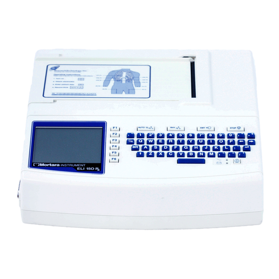
Figure 1-5, ELI 150 Rx Display and Keyboard ……. . .
-
Page 22
Table of Contents (Continued) SYSTEM SETTINGS SECTION 4 Section Purpose …………….. . 23 Accessing Configuration Menus . -
Page 23: Introduction Section
Indications for Use The ELI 150 Rx is indicated for use in a clinical setting by qualified medical professionals only for recording ECG data of patients. • The device is indicated for use to acquire, analyze, display, and print ECG data for consideration by physicians.
-
Page 24: System Description
SECTION 1 System Description The ELI 150 Rx is a 12-lead diagnostic electrocardiograph capable of acquiring, viewing, transmitting, printing, and storing ECG data. The device is optionally equipped with Mortara Instrument’s VERITAS™ resting ECG interpretation algorithm with age and gender specific criteria. If this option is enabled (see Section 4) the VERITAS algorithm can provide an over-reading physician with a silent second opinion through diagnostic statements output on the ECG report.
-
Page 25
SECTION 1 ELI 150 Rx, Left Side Figure 1-2 ELI 150 Rx, Rear Figure 1-3… -
Page 26
SECTION 1 ELI 150 Rx, Base Figure 1-4… -
Page 27: Automatic Feature Keys
SECTION 1 ELI 150 Rx, Display and Keyboard Figure 1-5 Automatic Feature Keys Automatic feature keys are used as a one-touch operation for: ECG Acquisition Rhythm Printing Transmitting Stop…
-
Page 28: Display Overview
• Heart Rate (HR): When a patient is connected to the ELI 150 Rx, his/her HR is displayed in real time. The HR is the average ventricular rate measured over an average of the patient’s last five beats.
-
Page 29: Eli 150 Rx Specifications
SECTION 1 ELI 150 Rx Specifications Feature Specifications Instrument Type 12-lead electrocardiograph Input Channels Simultaneous acquisition of all 12 leads Standard Leads Acquired I, II, III, aVR, aVL, aVF, V1, V2, V3, V4, V5, V6 Waveform Display Backlit, 1/4 VGA LCD…
-
Page 30: Accessories
SECTION 1 Accessories Part Number Description 9100-028-01 ELI 150 Rx 4.25” x 5.5” thermal paper, cued Z-fold, full grid 9293-032-50 ELI standard patient cable, 12-lead, banana – AHA 9293-032-51 ELI standard patient cable, 12-lead, banana – IEC 9293-033-50 ELI standard patient cable, 12-lead, snap – AHA 9293-033-51 ELI standard patient cable, 12-lead, snap –…
-
Page 31: Equipment Preparation Section
EQUIPMENT PREPARATION SECTION 2 Section Purpose This section is intended to provide the user with information about: • Connecting the patient cable. • Loading paper. • Applying power. • Setting time, date, and LCD contrast. Connecting the Patient Cable Figure 2-1 Connect patient cable to the side connector…
-
Page 32: Loading Paper
š Slide writer cover to the right until the cover latches in a locked position. You will hear a sharp click when the door is properly latched. WARNING: Risk of injury to fingers in writer paper door or platen drive mechanisms. NOTE: For proper performance of thermal writer, be certain to use Mortara recommended thermal paper.
-
Page 33: Applying Power
Applying Power ‚ Plug the power cord into an AC wall outlet and into the back of the ELI 150 Rx. (Reference Figure 1-3.) Device powers on automatically and cannot be turned off when AC is connected (device is in Standby mode).
-
Page 34
SECTION 2… -
Page 35: Record An Ecg Section
RECORD AN ECG SECTION 3 Section Purpose This section is intended to provide the user with information about: • Patient preparation. • Patient hookup. • Patient demographic entry. • Acquiring, printing, and storing an ECG. • Acquiring rhythm strips. • Optional bar code scanner. Patient Preparation Before attaching the electrodes, assure the patient fully understands the procedure and what to expect.
-
Page 36: Patient Hookup
SECTION 3 Patient Hookup Correct electrode placement is important for acquiring a successful ECG. A good minimum-impedance pathway will provide superior noise-free waveforms. Good quality silver-silver chloride (Ag/AgCl) electrodes should be used. TIP: Electrodes should be stored in an air-tight container. Electrodes will dry out if not stored properly which will cause loss of adhesion and conductivity.
-
Page 37
SECTION 3 For accurate V-lead placement and monitoring, it is important to locate the 4th intercostal space. The 4th intercostal space is determined by first locating the 1st intercostal space. Because patients vary with respect to body shape, it is difficult to palpate the 1st intercostal space with accuracy. Thus, locate the 2nd intercostal space by first palpating the little bony prominence called the Angle of Lewis, where the body of the sternum joins the manubrium. -
Page 38: Patient Hookup Summary Table
SECTION 3 Patient Hookup Summary Table AAMI Lead IEC Lead Electrode Position Right side of the sternum in the 4th intercostal space. Left side of the sternum in the 4th intercostal space. Midway between V2/C2 and V4/C4. Left midclavicular line in the 5th intercostal space.
-
Page 39: Patient Demographic Entry
The patient demographic labels available are determined by the ID format selected in the configuration settings. In addition to short, standard, or long patient ID formats, the ELI 150 Rx also supports a custom ID format. The custom format, designed in an ELI LINK or E-Scribe™ Rx data management system, can be downloaded to the ELI 150 Rx.
-
Page 40: Ecg Acquisition, Printing, Storage
ECG is free from artifact (noise) due to patient activity. If workflow permits patient demographic entry prior to acquisition, connect the patient to the ELI 150 Rx and enter the patient identification information as explained in Patient Demographics. After you complete the last data entry field, select F6 (Done) to return to the real-time ECG view.
-
Page 41: Printing
ECG view. Storage The ELI 150 Rx manages storage in one of two ways – automatically or manually. When the auto-save configuration option is enabled, ECGs are automatically saved to the directory upon acquisition and printing. When the auto-save configuration option is disabled, the user is prompted to save the ECG after acquisition.
-
Page 42: Acquiring Rhythm Strips
See Section 4 for instructions to configure rhythm leads. Begin routine rhythm strips by connecting the patient to the ELI 150 Rx and entering the patient identification information. After the last data entry field from the ID menu is completed, select F6 (Done) to return to the real-time ECG view.
-
Page 43: Optional Bar Code Scanner
Mortara’s optional bar code scanner is purchased separately. By connecting the bar code scanner to the ELI 150 Rx’s RS-232 (serial port), all aspects of acquiring an ECG are automated for speed and accuracy of alphanumeric entry, functions, and feature processes.
-
Page 44
SECTION 3… -
Page 45: System Settings Section
SYSTEM SETTINGS SECTION 4 Section Purpose This section is intended to provide the user with information about: • Accessing configuration menus. • Summary of configuration options. • Detailed descriptions of configuration settings. Accessing Configuration Menus The configuration pages define all operational conditions that do not change on a daily or patient-to-patient basis.
-
Page 46: Summary Of Configuration Menus
SECTION 4 The following chart summarizes the configuration parameters and the available options for each field. Summary of Configuration Menus CONFIGURATION PARAMETER DEFINITION Software Version The software version of the unit Cart Number User defined (4 digits; 0 to 9999) Site Number User defined (4 digits;…
-
Page 47
SECTION 4 Summary of Configuration Menus (continued) CONFIGURATION PARAMETER DEFINITION 6 Rhythm Lead 4 V1-V6, I, II, III, aVR, aVL, aVF 6 Rhythm Lead 5 V1-V6, I, II, III, aVR, aVL, aVF 6 Rhythm Lead 6 V1-V6, I, II, III, aVR, aVL, aVF Plot Format Channels printed: 3, 3+1, 3+3;… -
Page 48: Configuration
Site Number (Second and Third site as well) The ELI 150 Rx allows for the configuration of up to three site numbers in order to manage multiple studies. A site is defined as a location from where an ECG is transmitted. In a research environment, it is recommended that site numbers designate the investigator’s site for ECG records stored in an E-Scribe Rx data management…
-
Page 49
SECTION 4 Language There are several languages available on the electrocardiograph. CAUTION: Function labels are immediately translated upon selecting a new language and exiting the configuration screen. If an unknown language is visible, use the following steps to revert to the language of your country: 1. -
Page 50: Configuration
AC Filter The ELI 150 Rx removes 60 Hz or 50 Hz interference. The setting you select depends on the line frequency in your country. Always use the 60 Hz setting in the U.S. If AC interference is present, check to see that the proper AC filter is selected.
-
Page 51
ECG. Using the example above, the acquisition date will print as 16-Jul-2003. Interpretation Option The ELI 150 Rx automatically analyzes ECGs and prints the optional interpretation on the ECG printout. This setting allows you to select or suppress the “interpretive” text on the ECG report. -
Page 52: Configuration
Defines whether or not a newly acquired ECG will be automatically saved to the directory once it is acquired and printed. If the auto-save configuration option is set to No and the record is printed, the ELI 150 Rx will prompt you to “Save ECG?” F1 (SAVE) will store the ECG in the directory.
-
Page 53: Configuration
SECTION 4 Auto-Print ECG Defines whether or not the ELI 150 Rx will automatically print the ECG after acquisition. If the selected configuration option is set to No, a manual printout is possible. Baud Rate Determines the serial port’s data transmission rate in bits per second (bps). Set the baud rate to 9600, 19200, 38400, 57600, or 115200 bps for direct data transmission between the ELI 150 Rx and another Mortara electrocardiograph;…
-
Page 54: Configuration
SECTION 4 Configuration Page 5 Plot Format Defines the default for one of the available plot formats in either standard or Cabrera presentation. Please note that regardless of the plot format selected, 10 seconds of 12 leads are always stored. The ECG plot options are: Format Option ECG Data…
-
Page 55: Configuration
Enter the port number used by the host server. SSID Service Set Identifier (SSID) is the name of the wireless network. All ELI 150 Rx electrocardiographs that will transmit to the same network must have the same SSID name. This field is case sensitive.
-
Page 56: Configuration
Enter the 128-bit WEP key ID value (26 digits in 13 sets of two digits). WLAN MAC Shows the MAC address of the ELI 150 Rx wireless module for configuring access points. WPA-PSK WPA (Wi-Fi Protected Access) PSK (Pre-Shared Key) security allows for implementation of the “personal mode”…
-
Page 57: Configuration
Enter technician password. Worklist Management The ELI 150 Rx can download and process ECG order lists from the E-Scribe Rx or another compatible information management system which identifies the ECGs (or ECG orders) needed for particular patients. Implementation of an order-based workflow can significantly reduce demographic data entry errors at the electrocardiograph.
-
Page 58
SECTION 4… -
Page 59: Section Purpose
• ECG directory and directory maintenance. • Print configuration. The ELI 150 Rx offers several special functions available through the application menu. Select F6 (More) from the real-time ECG view and the application menu is displayed. The following chart summarizes the application functions available.
-
Page 60: Print Configuration
(with an “X” in the appropriate column). F6 (Exit) to return to the ECG directory. Print Configuration In order to verify the ELI 150 Rx’s configuration settings, a printout of the device’s configuration is possible from the application menu by selecting 2 (Print Configuration). The configuration printout captures every configuration setting: the software version, the cart number of the device, and the date and time that the configuration printout occurred.
-
Page 61: Connectivity And Ecg Transmission
NOTE: Telephone transmission is available with GSM/GPRS mobile or internal modem only. NOTE: In order to properly connect to telephone lines, the ELI 150 Rx internal modem needs to be set on the proper country code. This is an internal setting and should not be confused with International calling codes.
-
Page 62: Direct Connection (Rs-232)
Modem Transmission For a modem transmission, set the XMT media to modem. Connect the ELI 150 Rx to a standard telephone jack with the provided phone line cable. Plug the cable into the telephone jack located on the back of the electrocardiograph and the other end into a telephone wall jack.
-
Page 63: External Modem Country Code List
APPENDIX A EXTERNAL MODEM COUNTRY CODE LIST: Country Code Country Code Afghanistan(AF) Chile(CL) Albania(AL) China(CN) Algeria(DZ) Christmas Island(CX) American Samoa(AS) Cocos (Keeling) Islands(CC) Andorra(AD) Colombia(CO) Angola(AO) Comoros(KM) Anguilla(AI) Congo(CG) Antarctica(AQ) Cook Islands(CK) Antigua and Barbuda(AG) Costa Rica(CR) Argentina(AR) Cote D’Ivoire(CI) Armenia(AM) Croatia(HR) Aruba(AW)
-
Page 64
APPENDIX A Country Code Country Code Greenland(GL) Mali(ML) Grenada(GD) Malta(MT) Guadeloupe(GP) Marshall Islands(MH) Guam(GU) Martinique(MQ) Guatemala(GT) Mauritania(MR) Guinea(GN) Mauritius(MU) Guinea-Bissau(GW) Mayotte(YT) Guyana(GY) Mexico(MX) Haiti(HT) Micronesia(Federated States of)(FM) Heard and Mc Donald Islands(HM) Moldova-Republic of(MD) Honduras(HN) Monaco(MC) Hong Kong(HK) Mongolia(MN) Hungary(HU) Montserrat(MS) Iceland(IS) Morocco(MA) -
Page 65
APPENDIX A Country Code Country Code Rwanda(RW) Thailand(TH) St. Helena(SH) Togo(TG) Saint Kitts and Nevis(KN) Tokelau(TK) Saint Lucia(LC) Tonga(TO) St. Pierre and Miquelon(PM) Trinidad and Tobago(TT) Saint Vincent and the Grenadines(VC) Tunisia(TN) Samoa(WS) Turkey(TR) San Marino(SM) Turkmenistan(TM) Sao Tome and Principe(ST) Turks and Caicos Islands(TC) Saudi Arabia(SA) Tuvalu(TV) -
Page 66: Wlan Transmission
NOTE: The range for the WEP key is 0-3. If the range on your access point is 1-4, then 0 at the ELI 150 Rx maps to 1 on the access point; 1 maps to 2 on the access point, etc.
-
Page 67: Lan Transmission
LAN Transmission For a LAN transmission, connect the ethernet cable to the LAN connection at the rear of the ELI 150 Rx and set the XMT media to LAN in the configuration. It is necessary that the IT Manager of your facility set the ELI 150 Rx LAN configuration values.
-
Page 68: Sim Card Installation
SIM Card Installation Power off the ELI 150 Rx. Open the writer cover and remove the pack of thermal paper. There is a small access panel on the floor of the writer tray. Remove the screw and lift off the access panel.
-
Page 69: Orders Download
Rx system. The technician at the electrocardiograph selects the desired order code (e.g., a code specific to a department or floor) and the patients belonging to the order list. Once downloaded to the ELI 150 Rx, the ECG list for the selected order code is stored in the device as the order list (similar to the ECG directory). As with ECG data transmission, you can use any of the connectivity options to download the order list.
-
Page 70: Custom Id Download
Custom ID formats are uniquely defined by your facility’s needs. This customized ECG header information is designed in an ELI LINK or E-Scribe Rx system and downloaded to the ELI 150 Rx. Up to three custom ID formats can be downloaded.
-
Page 71: Maintenance And Troubleshooting
MAINTENANCE AND TROUBLESHOOTING APPENDIX B System Troubleshooting Chart LCD Message Problem Correction BATTERY LOW – Unable to acquire ECG Charge the battery with AC power. CHARGE UNIT or unable to print. LEAD FAULT, NO Lead fail or noisy ECG data. Correct faulty lead or noise.
-
Page 72
A link to the access point could Ensure the IP address is correct. If problem ACCESS POINT not be established. persists, contact Mortara Technical Service. CAN’T CONNECT TO A link to the access point was Ensure the IP address is correct. If problem… -
Page 73: Test Operation
The sealed lead-acid battery will provide optimum life when the unit is fully charged after each use. The ELI 150 Rx will charge a depleted battery to 90% of its capacity in approximately 8 hours or less. To recharge a battery from its lowest level, 30 hours of recharging without operation will be necessary.
-
Page 74
APPENDIX B… -
Page 75: Glossary
GLOSSARY GLOSSARY TERM DEFINITION AAMI ECG lead names and identifying colors recommended by the Association for the Advancement of Medical Instrumentation. AC filter The configurable filter which screens out ECG artifact caused by power line interference. Artifact ECG waveform distortion that may diminish the quality of the ECG signal and may be caused by electrical interference, poor electrodes, poor patient prep, or poor connection.
-
Page 76
GLOSSARY TERM DEFINITION Order Term for a physicians request for a 12-lead electrocardiogram. Power saving mode Term used for the electrocardiograph turning itself into a standby mode. The factory default is 10 minutes without operation or any ECG signal being detected. Precordial leads See Chest Leads.
Электрокардиограф ELI 150c – это медицинский прибор экспертного класса, который отвечает передовым стандартам качества. Он позволяет регистрировать 12 каналов ЭКГ. В устройстве есть встроенный алгоритм интерпретации ЭКГ VERITAS AnalysisAlgorithm – его разработали на основе информации из медицинских клиник и центров за 20 лет.
В электрокардиографе есть встроенный термопринтер, поэтому в комплекте к прибору идёт упаковка термобумаги. Также к прибору в наборе идут многоразовые хлорсеребряные электроды – 6 грудных и 4 для конечностей.
Просматривать кардиограмму можно с помощью цветного жидкокристаллического дисплея с подсветкой, его размер – 320*240. Также есть буквенно-цифровая клавиатура для ввода данных о пациенте.
На электрокардиографе Mortara ELI 150c можно хранить до 100 записей ЭКГ, однако опционально можно установить более мощный накопитель с объёмом памяти до 200 записей ЭКГ. Конечно же, есть возможность их передачи на другой носитель, в частности на персональный компьютер.
В приборе для качественной работы установлено несколько фильтров:
- сетевых помех;
- нижних частот
- центральный фильтр изолинии.
Подключать к питанию прибор можно либо кабелем от сети, либо с помощью внутреннего аккумулятора.
Сравнение кардиографов ELI:
| ELI 150c | ELI 250c | ELI 10 | |
| Кол-во каналов ЭКГ | 12 | 12 | 12 |
| Мобильная тележка | опция | опция | опция |
| Дисплей | цветной | цветной | моно |
| VERITAS AnalysisAlgorithm | + | + | + |
| Встроенная клавиатура QWERTY | + | + | + |
| Встроенный накопитель (до 60 записей ЭКГ) | + | + | + |
| Встроенный накопитель (до 150 записей ЭКГ) | опция | опция | опция |
| Возможность обмена данными с ПК | + | + | + |
| Возможность печати на полноразмерную бумагу (8.5″x11″ или A4) | — | + | -/+ |
| Набор стандартных аксессуаров | + | + | + |
Комплект поставки электрокардиографа ELI 150c с цифровым беспроводным кабелем пациента WAM:
— Электрокардиограф ELI 150c – 1шт.
— Беспроводный кабель пациента на 10 отведений WAM – 1 шт.
— Комплект многоразовых ЭКГ электродов AgCl (6 грудных, 4 для конечностей) — 1 уп.
— Термобумага – 1 шт (пачка 108мм х 140мм х 200 листов).
— Кабель питания – 1 шт.
Технические характеристики:
— Тип оборудования 12 канальный электрокардиограф
— Входные каналы Одновременная регистрация 12 каналов ЭКГ
— Регистрация стандартных отведений I, II, III, aVR, aVL, аVF, V1, V2, V3, V4, V5, V6
— Дисплей Цветной жидкокристаллический дисплей с разрешением 320 х 240 пикселей с подсветкой
— Разрядность АЦП 20 бит
— Частота дискретизации 40 000 Гц/канал при регистрации работы с водителем ритма; 1000 Гц /канал при снятии и анализе ЭКГ
— Термопринтер Разрешающая способность 8 точек/мм
— Тип бумаги Термочувствительная Z-образная бумага в пачках, размерами 108 мм х 140 мм х 200 листов
— Скорость печати 5, 10, 25, 50 мм/сек
— Чувствительность 5, 10, 20 мм/мВ
— Формат печати отчета 3, 3+1, 3+3 канала или 6 каналов
— Формат печати ритма 3 или 6 каналов с конфигурацией групп отведений
— Тип клавиатуры Полная алфавитно-цифровая клавиатура, с функциональными клавишами
— Частотный диапазон 0,05 – 300 Гц
— Фильтры Цифровой фильтр изолинии;
— Фильтр сетевой помехи 50/60 Гц;
— Фильтр нижних частот 40 Гц; 150 Гц; 300 Гц
— Электробезопасность Класс 1, Тип CF
— Память До 100 ЭКГ (до 200 ЭКГ опция)
— Вес 3,3 кг (включая батарею)
— Размеры 29,2 х 30,5 х 10,2 мм
— Питание Универсальное питание: от сети переменного тока (100-240 В, частота 50/60Гц) или внутренний аккумулятор
Электрокардиограф ELI 150C – 12-канальный электрокардиограф с встроенным ЖК монитором (разрешение 320х240), термопринтером для печати ЭКГ на бумаге шириной 108 мм, полной алфавитно-цифровой клавиатурой, памятью на 100 ЭКГ исследований и цифровым кабелем пациента AM12™ или беспроводным WAM. Электрокардиограф имеет универсальное питание – сеть/аккумулятор. Функция Best 10 (автоматический выбор наилучших 10 секунд сигнала ЭКГ для отображения на дисплее или печати на термопринтер). Опционально поставляются: алгоритм интерпретации ЭКГ для взрослых и детей (VERITAS), передача данных через Ethernet/WLAN/GPRS, передача ЭКГ данных в формате DICOM, загрузка ЭКГ данных на ПК через USB.
Основные преимущества
- Портативность и функциональность.
Компактный 2-канальный электрокардиограф Mortara ELI 150C обеспечивает комплексную функциональность в переносной конструкции и поэтому является оптимальным решением для амбулаторий, бригад скорой помощи, стационаров, поликлиник и частных медицинских центов.
- Информативный цветной ЖК-дисплей.
Предварительный просмотр всех 12 отведений (каналов) перед печатью ЭКГ. Отображение частоты сердечных сокращений (ЧСС), скорости печати, чувствительности (усиление), активированных фильтров, времени и индикация качества наложения электродов.
- Высокое качество диагностики.
Частота дискретизации 40 000 Гц гарантирует достоверное обнаружение импульсов кардиостимулятора.
- Уникальный алгоритм интерпретации ЭКГ – VERITAS.
Уникальный алгоритм Mortara VERITAS позволяет проводить автоматический и высоко достоверный анализ ЭКГ как взрослых, так и у детей. Педиатрический алгоритм реализован для 11 возрастных групп с первой недели жизни и до 16 лет.
- Алгоритм определения ошибки наложения электродов.
С целью экономии времени медперсонала и избежание повторного снятия ЭКГ вэлектрокардиограф встроен алгоритм определения ошибки наложения электродов, который сигнализирует пользователю в случае, если отведения перепутаны местами.
- Цифровой кабель пациента.
Выбор беспроводного кабеля пациента WAMили проводного АМ12 обеспечивает удобство и комфорт в работе и позволяет добиться высокого качества ЭКГ записи. Оба кабеля оснащены сменными проводами, кнопками управления для быстрой регистрации и печати ЭКГ.
Для уменьшения времени снятия ЭКГ и увеличения пропускной способности электрокардиографа при работе на потоке, электрокардиограф автоматически выбирает лучшие 10 секунд ЭКГ записи для отображения на дисплее или печати.
- Универсальное питание.
Благодаря питанию, как от сети, так и от внутреннего аккумулятора электрокардиограф может использоваться, как стационарное, так и переносное устройство.
- Обмен информацией.
Возможность передачи ЭКГ данных между устройствами и компьютерами благодаря внутреннему модему, LAN (локальная сеть) или беспроводной локальной сети в E-Scribe. Возможность передачи ЭКГ данных в DICOM формате.
| Параметр | Значение |
| Максимальное количество регистрируемых каналов | 12 |
| Одновременная печать (каналов) | 12 |
| Ширина бумаги | 108 мм |
| Тип бумаги | пачка |
| Размер дисплея | 4 дюйма |
| Тип дисплея | цветной сенсорный |
| Клавиатура (буквы цифры) | да |
| Программное обеспечение | да |
| Автоматическая интерпретация | да |
| Встроенный аккумулятор | да |
| Транспортная сумка | опция |
| Вес | 3 кг |
Комплект поставки
- Электрокардиограф ELI 150C – 1 шт.
- Кабель пациента на 10 отведений АМ12 или беспроводный кабель пациента на 10 отведений WAM для поставки электрокардиографа с цифровым беспроводным кабелем пациента WAM — 1 шт.
- Комплект многоразовых ЭКГ электродов AgCl (6 грудных, 4 для конечностей) — 1 уп.
- Термобумага – 1 шт. (пачка 108 мм х 140 мм х 200 листов).
- Кабель питания – 1 шт.
Регистрационное удостоверение на медицинское изделие РЗН 2013/279
Внимание, документ содержит изменения:
История вносимых изменений
Фактический адрес изготовителя
Юридический адрес изготовителя
Электрокардиограф ELI с принадлежностямиварианты исполнения: ELI150c, ELI250c, ELI230.
Принадлежности:
1. Передвижная тележка для монтажа системы.
2. Гибкий штатив для передвижной тележки.
3. Дополнительная корзина для передвижной тележки.
4. Клавиатура.
5. ЖК дисплей.
6. Модем.
7. Адаптер для модема.
8. Интерфейсный кабель для модема.
9. Термопринтер.
10. Координатная бумага для термопринтера.
11. Печатающая головка для термопринтера.
12. Блок питания для термопринтера.
13. Аккумуляторная батарея.
14. Усилитель ЭКГ.
15. Устройство для считывания штрих-кодов.
16. Беспроводной модуль пациента.
17. Аккумуляторная батарея беспроводного модуля пациента.
18. Зарядное устройство для аккумуляторной батареи.
19. Проводной модуль пациента.
20. Сумка для переноски и хранения аппарата.
21. Кабель пациента для беспроводного модуля пациента, 10 отведений.
22. Кабель пациента для беспроводного модуля пациента, 10 отведений, удлиненный.
23. Кабель пациента для беспроводного модуля пациента, 13 отведений.
24. Кабель пациента для беспроводного модуля пациента, 13 отведений, удлиненный.
25. Кабель пациента для беспроводного модуля пациента, со сменными отведениями.
26. Кабель пациента для проводного модуля пациента, 10 отведений.
27. Кабель пациента для проводного модуля пациента, 10 отведений.
28. Кабель пациента для проводного модуля пациента, 10 отведений, удлиненный.
29. Кабель пациента для проводного модуля пациента, 13 отведений.
30. Кабель пациента для проводного модуля пациента, со сменными отведениями.
32. Стартовые наборы для наложения электродов ЭКГ (не более 100шт.).
33. Аппликационные электроды ЭКГ (не более 100000шт.).
34. Вакуумные электроды ЭКГ (не более 12шт.).
35. Электроды ЭКГ на конечности (не более 8шт.).
36. Педиатрические аппликационные электроды ЭКГ (не более 100000шт.).
37. Педиатрические вакуумные электроды ЭКГ (не более 12шт.).
38. Педиатрические электроды ЭКГ на конечности (не более 8шт.).
39. Аппликационные мониторинговые электроды ЭКГ (не более 100000шт.).
40. Переходники для электродов типа «кнопка» (не более 30шт.).
41. Переходники для электродов типа «аллигатор» (не более 30шт.).
42. Переходники для электродов типа «штекер» (не более 30шт.).
43. Контактный спрей ЭКГ.
44. Контактный гель ЭКГ.
45. Диск с программным обеспечением.
46. Конфигурационный диск.
47. Руководство пользователя.
48. Краткое руководство пользователя.
49. Руководство техника.
50. Информационные наклейки (не более 100 шт.).
51. Сервисный набор для проведения обслуживания аппарата.
ЗАО «Медицинские системы»
Подробнее
Развернуть

REF 9515-177-50-ENG Rev A1
ELI 150c/ELI 250c
12-LEAD RESTING ELECTROCARDIOGRAPH
USER MANUAL
Manufactured by Mortara Instrument, Inc., Milwaukee, Wisconsin U.S.A.
CAUTION: Federal law restricts this device to sale by or on the order of a physician.

Copyright © 2011
by Mortara Instrument, Inc. 7865 N. 86th Street Milwaukee, Wisconsin 53224
This document contains confidential information that belongs to Mortara Instrument, Inc. No part of this document may be transmitted, reproduced, used, or disclosed outside of the receiving organization without the express written consent of Mortara Instrument, Inc. Mortara is a registered trademark of Mortara Instrument, Inc. E-Scribe, ELI, and VERITAS are trademarks of Mortara Instrument, Inc. Cisco® is the registered trademark of Cisco Systems, Inc. DICOM® is the registered trademark of the National Electrical Manufacturers Association for its standards publications relating to digital communications of medical information. V1.00.

TECHNICAL SUPPORT AND SERVICE
Headquarters
Mortara Instrument, Inc.
7865 North 86th Street
Milwaukee, WI 53224 U.S.A.
Tel: 414.354.1600
Tel: 800.231.7437
Fax: 414.354.4760
Internet: http://www.mortara.com
European Union
Representative
Mortara Rangoni Europe, Srl
(European Headquarters) Via Cimarosa 103/105
40033 Casalecchio di Reno (BO) Italy
Tel: +39.051.298.7811 Fax: +39.051.613.3582
Service/Technical
Support Group
Mortara Instrument, Inc.
7865 North 86th Street
Milwaukee, WI 53224 U.S.A.
Tel: 414.354.1600 Service: 888.MORTARA
(888.667.8272) Fax: 414.354.4760
E-mail: techsupport@mortara.com
24-hour Technical Support
Same-day Shipment of Replacement Parts
Biomedical Training Classes
Extended Warranties/Service Contracts
Sales Support/
Supplies & Accessories
Mortara Instrument, Inc.
7865 North 86th Street
Milwaukee, WI 53224 U.S.A.
Tel: 414.354.1600 Fax: 414.354.4760
E-mail: sales@mortara.com
Mortara Instrument Germany
Kaninenberghöhe 50
45136 Essen
|
Germany |
|
|
Tel: |
+49.201.18 55 69 70 |
|
Fax: |
+49.201.18 55 69 77 |
Mortara Instrument Netherlands
Postbus 324
5680 AH Best
Industrieweg 160b
5683 CG Best
Netherlands
Tel: +31.499.377310
Fax: +31.499.377908
Mortara Instrument Australia
PO Box 7568
Baulkham Hills NSW 2153
Unit 28, 9 Hoyle Avenue
Castle Hill NSW 2154
Australia
|
Tel: |
+61 2 8070 9303 |
|
Fax: |
+61 2 9899 9478 |
i

NOTICES
Manufacturer’s Responsibility
Mortara Instrument, Inc. is responsible for the effects on safety and performance only if:
•Assembly operations, extensions, readjustments, modifications, or repairs are carried out only by persons authorized by Mortara Instrument, Inc.
•The device is used in accordance with the instructions for use.
Responsibility of the Customer
The user of this device is responsible for ensuring the implementation of a satisfactory maintenance schedule. Failure to do so may cause undue failure and possible health hazards.
Equipment Identification
Mortara Instrument, Inc. equipment is identified by a serial and reference number on the back of the device. Care should be taken so that these numbers are not defaced.
Copyright and Trademark Notices
This document contains information that is protected by copyright. All rights are reserved. No part of this document may be photocopied, reproduced, or translated to another language without prior written consent of Mortara Instrument, Inc.
Other Important Information
The information in this document is subject to change without notice.
Mortara Instrument, Inc. makes no warranty of any kind with regard to this material including, but not limited to, implied warranties of merchantability and fitness for a particular purpose. Mortara Instrument, Inc. assumes no responsibility for any errors or omissions that may appear in this document. Mortara Instrument, Inc. makes no commitment to update or to keep current the information contained in this document.
ii

WARRANTY INFORMATION
Your Mortara Warranty
MORTARA INSTRUMENT, INC. (hereinafter referred to as “Mortara”) hereby warrants that Mortara products (hereinafter referred to as “Product/s”) shall be free from defects in material and workmanship under normal use, service, and maintenance for the warranty period of such Product/s from Mortara or an authorized distributor or representative of Mortara. The warranty period is defined as twenty-four (24) months following the date of shipment from Mortara. Normal use, service, and maintenance means operation and maintenance in accordance with appropriate instructions and/or information guides. This warranty does not apply to damage to the Product/s caused by any or all of the following circumstances or conditions:
a)Freight damage;
b)Parts and/or accessories of the Product/s not obtained from or approved by Mortara;
c)Misapplication, misuse, abuse, and/or failure to follow the Product/s instruction sheets and/or information guides;
d)Accident; a disaster affecting the Product/s;
e)Alterations and/or modifications to the Product/s not authorized by Mortara;
f)Other events outside of Mortara’s reasonable control or not arising under normal operating conditions.
THE REMEDY UNDER THIS WARRANTY IS LIMITED TO THE REPAIR OR REPLACEMENT WITHOUT CHARGE FOR LABOR OR MATERIALS, OR ANY PRODUCT/S FOUND UPON EXAMINATION BY MORTARA TO HAVE BEEN DEFECTIVE. This remedy shall be conditioned upon receipt of notice by Mortara of any alleged defects promptly after discovery thereof within the warranty period. Mortara’s obligations under the foregoing warranty will further be conditioned upon the assumption by the purchaser of the Product/s (i) of all carrier charges with respect to any Product/s returned to Mortara’s principal place or any other place as specifically designated by Mortara or an authorized distributor or representative of Mortara, and (ii) all risk of loss in transit. It is expressly agreed that the liability of Mortara is limited and that Mortara does not function as an insurer. A purchaser of a Product/s, by its acceptance and purchase thereof, acknowledges and agrees that Mortara is not liable for loss, harm, or damage due directly or indirectly to an occurrence or consequence therefrom relating to the Product/s. If Mortara should be found liable to anyone under any theory (except the expressed warranty set forth herein) for loss, harm, or damage, the liability of Mortara shall be limited to the lesser of the actual loss, harm, or damage, or the original purchase price of the Product/s when sold.
EXCLUDED FROM THE LIMITED WARRANTY SET FORTH ABOVE ARE CONSUMABLE ITEMS SUCH AS PAPER, BATTERIES, ELECTRODES, PATIENT CABLES, LEAD WIRES, AND MAGNETIC STORAGE MEDIUMS.
EXCEPT AS SET FORTH HEREIN WITH RESPECT TO REIMBURSEMENT OF LABOR CHARGES, A PURCHASER’S SOLE EXCLUSIVE REMEDY AGAINST MORTARA FOR CLAIMS RELATING TO THE PRODUCT/S FOR ANY AND ALL LOSSES AND DAMAGES RESULTING FROM ANY CAUSE SHALL BE THE REPAIR OR REPLACEMENT OF DEFECTIVE PRODUCT/S TO THE EXTENT THAT THE DEFECT IS NOTICED AND MORTARA IS NOTIFIED WITHIN THE WARRANTY PERIOD. IN NO EVENT, INCLUDING THE CLAIM FOR NEGLIGENCE, SHALL MORTARA BE LIABLE FOR INCIDENTAL, SPECIAL, OR CONSEQUENTIAL DAMAGES, OR FOR ANY OTHER LOSS, DAMAGE, OR EXPENSE OF ANY KIND, INCLUDING LOSS OF PROFITS, WHETHER UNDER TORT, NEGLIGENCE OR STRICT LIABILITY THEORIES OF LAW, OR OTHERWISE. THIS WARRANTY IS EXPRESSLY IN LIEU OF ANY OTHER WARRANTIES, EXPRESS OR IMPLIED, INCLUDING, BUT NOT LIMITED TO THE IMPLIED WARRANTY OF MERCHANTABILITY AND THE WARRANTY OF FITNESS FOR A PARTICULAR PURPOSE.
iii

WARRANTY INFORMATION
iv

USER SAFETY INFORMATION
Warning: Means there is the possibility of personal injury to you or others.
Caution: Means there is the possibility of damage to the device.
Note: Provides information to further assist in the use of the device.
Warning(s)
•This manual gives important information about the use and safety of this device. Deviating from operating procedures, misuse or misapplication of the device, or ignoring specifications and recommendations could result in increased risk of harm to users, patients and bystanders, or damage to the device.
•Device captures and presents data reflecting a patient’s physiological condition that when reviewed by a trained physician or clinician can be useful in determining a diagnosis; however, the data should not be used as a sole means for determining a patient’s diagnosis.
•Users are expected to be licensed clinical professionals knowledgeable about medical procedures and patient care, and adequately trained in the use of this device. Before attempting to use this device for clinical applications, the operator must read and understand the contents of the user manual and other accompanying documents. Inadequate knowledge or training could result in increased risk of harm to users, patients and bystanders, or damage to the device. Contact Mortara service for additional training options.
•To ensure that electrical safety is maintained during operation from AC (~) power, the device must be plugged into a hospital-grade outlet.
•To maintain designed operator and patient safety, peripheral equipment and accessories used that can come in direct patient contact must be in compliance with UL 60601-1, IEC 60601-1, and IEC 60601-2-25. Only use parts and accessories supplied with the device and available through Mortara Instrument, Inc.
•Patient cables intended for use with the device include series resistance (9 Kohm minimum) in each lead for defibrillation protection. Patient cables should be checked for cracks or breakage prior to use.
•Conductive parts of the patient cable, electrodes, and associated connections of type CF applied parts, including the neutral conductor of the patient cable and electrodes, should not come into contact with other conductive parts including earth ground.
•ECG electrodes could cause skin irritation; patients should be examined for signs of irritation or inflammation.
•To avoid the possibility of serious injury or death during patient defibrillation, do not come into contact with device or patient cables. Additionally, proper placement of defibrillator paddles in relation to the electrodes is required to minimize harm to the patient.
v

USER SAFETY INFORMATION
•This device was designed to use the electrodes specified in this manual. Proper clinical procedure must be employed to prep the electrode sites and to monitor the patient for excessive skin irritation, inflammation, or other adverse reactions. Electrodes are intended for short-term use and should be removed from the patient promptly following testing.
•To avoid potential for spread of disease or infection, single-use disposable components (e.g., electrodes) must not be reused. To maintain safety and effectiveness, electrodes must not be used beyond their expiration date.
•To ensure the safety of both the patient and the device, 1.5 meters (5’) of open area should surround the patient.
•A possible explosion hazard exists. Do not use the device in the presence of a flammable anesthetic mixture.
•Where the integrity of external protective earth conductor arrangement is in doubt, the device shall be operated from its internal electrical power source.
•All signal input and output (I/O) connectors are intended for connection of only those devices complying with IEC 60601-1, or other IEC standards (e.g., IEC 60950) as appropriate to the device. Connecting additional devices to the device may increase chassis and/or patient leakage currents. To maintain operator and patient safety, consideration should be given to the requirements of IEC 60601-1-1, and leakage currents should be measured to confirm no electric shock hazard exists.
•To improve immunity to potential interfering electromagnetic signals, shielded cabling is recommended when connecting the device to a network.
•To maintain operator and patient safety, equipment connected to the same network as the device must meet the requirements of IEC 60950 or IEC 60601-1.
•To prevent electric shock due to unequal ground potentials that may exist between points of a distributed network system or fault conditions in external network connected equipment, network cable shielding (where used) must be connected to protective earth ground appropriate to the area where the device is used.
•The device has not been designed for use with high-frequency (HF) surgical equipment and does not provide a protective means against hazards to the patient.
•The quality of the signal produced by the device may be adversely affected by the use of other medical equipment, including but not limited to defibrillators and ultrasound machines.
•For proper operation and the safety of users or patients and bystanders, equipment and accessories must be connected only as described in this manual. Do not connect a telephone line cable to the LAN connector.
•Some Mortara electrocardiographs can be equipped with a GPRS (cellular modem) or wireless LAN (WLAN) module for transmitting ECG records. Device labeling and the presence of an antenna port will indicate if your device is equipped with such a module. If so equipped, the following notices apply:
•The GPRS module operates in allocated frequency bands depending on the model. Identification of the installed GPRS module can be found on a label on the bottom of the device.
•MultiTech Systems, Inc. Model MTSMC-G-F4 (Quad Band): 850/900/1800/1900 MHz, user selectable
•The WLAN identification can be found on a label on the bottom of the device.
•Quatech, Inc. Model WLNG-AN-DP101: 2400 MHz (model subject to change without notice)
vi

USER SAFETY INFORMATION
•Use of the GPRS or WLAN module may interfere with other equipment operating in the vicinity. Check with local authorities or spectrum management officials in your facility to determine if restrictions apply to the use of this feature in your area.
•Do not transmit via the GPRS or WLAN module with a missing or damaged antenna. Replace a damaged antenna immediately.
•Use only the antenna supplied for use with this device. Unauthorized antennas, modifications, or attachments could damage the GPRS module and may contravene local RF emission regulations or invalidate type approval.
•To ensure compliance with current regulations limiting both maximum RF output power and human exposure to radio frequency radiation, a separation distance of at least 20 cm must be maintained between the device’s antenna and the head and body of the user and any nearby persons at all times. To help prevent degradation of RF signal and to avoid excess RF energy absorption, do not touch the antenna during data transmission.
•The GPRS and WLAN modules comply with applicable RF safety standards including standards and recommendations for the protection of public exposure to RF electromagnetic energy that have been established by governmental bodies and other qualified organizations, such as the following:
•Federal Communications Commission (FCC)
•Directives of the European Community
•Directorate General V in Matters of Radio Frequency Electromagnetic Energy
Caution(s)
•To prevent possible damage to the keyboard, do not use sharp or hard objects to depress keys, only use fingertips.
•Do not attempt to clean the device or patient cables by submersing into a liquid, autoclaving, or steam cleaning as this may damage equipment or reduce its usable life. Wipe the exterior surfaces with a warm water and mild detergent solution and then dry with a clean cloth. Use of unspecified cleaning/disinfecting agents, failure to follow recommended procedures, or contact with unspecified materials could result in increased risk of harm to users, patients and bystanders, or damage to the device.
•No user-serviceable parts inside. Screw removal by qualified service personnel only. Damaged or suspected inoperative equipment must be immediately removed from use and must be checked/repaired by qualified service personnel prior to continued use.
•The rechargeable internal battery is a sealed lead-acid type and it is totally maintenance free. If the battery appears to become defective, refer to Mortara Instrument Service Department.
•Do not pull or stretch patient cables as this could result in mechanical and/or electrical failures. Patient cables should be stored after forming them into a loose loop.
•No calibration or special equipments are needed for the proper operation or maintenance of the device.
●When necessary, dispose of the device, its components and accessories (e.g., batteries, cables, electrodes), and/or packing materials in accordance with local regulations.
•Use only No. 26 AWG or larger telecommunication line cord.
vii

USER SAFETY INFORMATION
Note(s)
•Patient movements may generate excessive noise that may affect the quality of the ECG traces and the proper analysis performed by the device.
•Proper patient preparation is important to proper application of ECG electrodes and operation of the device.
•The algorithm detecting electrode misplacements is based on normal physiology and ECG lead order, and tries to identify the most likely switch; however, it is advisable to check the other electrode positions in the same group (limb or chest).
•There is no known safety hazard if other equipment, such as pacemakers or other stimulators, is used simultaneously with the device; however, disturbance to the signal may occur.
•If electrode is not properly connected to the patient, or one or more of the patient cable lead wires is damaged, display will indicate a lead fault for the lead(s) where the condition is present and if the signal is being printed, the respective lead(s) will print out as a square wave.
•As defined by IEC 60601-1 and IEC 60601-2-25, the device is classified as follows:
•Class I equipment or internally powered.
•Type CF defibrillation-proof applied parts.
•Ordinary equipment.
•Equipment not suitable for use in the presence of a flammable anesthetic mixture.
•Continuous operation.
NOTE: From a safety perspective, per IEC 60601-1 and derivative standards/norms, this device is declared to be “Class I” and uses a three-prong inlet to ensure an earth connection is made along with mains. The ground terminal on the mains inlet is the only protective earth point in the device. Exposed metal accessible during normal operation is double insulated from mains. Internal connections to earth ground are functional earth.
•This device is intended to be used in a hospital or doctor’s office setting, and should be used and stored according to the environmental conditions specified below:
|
Operating temperature: |
+10° to +40°C (+50° to +104°F) |
|
Operating humidity: |
10% to 95% RH, non-condensing |
|
Storage temperature: |
-40° to +70°C (-40° to +158°F) |
|
Storage humidity: |
10% to 95% RH, non-condensing |
|
Atmospheric pressure: |
500 hPa to 1060 hPa |
•WAM™ (wireless acquisition module) must be paired to electrocardiograph before operation.
•Device must be configured at the factory for use with the WAM.
•After operating the device using battery power, always reconnect the power cord. This ensures that the batteries will be automatically recharged for the next time you use the device.
viii
![]()
USER SAFETY INFORMATION
•The device is UL classified:
WITH RESPECT TO ELECTRIC SHOCK, FIRE AND MECHANICAL HAZARDS ONLY IN ACCORDANCE WITH UL60601-1, IEC60601-1, CAN/CSA C22.2 No. 601.1, IEC 60601-1-1, CAN/CSA C22.2 No. 60601- 1-1-02, IEC60601-2-25 AND CAN/CSA C22.2 No. 601.2.25-94.
•The device is a member of the ELI 1xx or ELI 2xx Series 2 electrocardiograph family.
Wireless Data Transmission
•Some Mortara electrocardiographs can be equipped with an optional wireless data transmission module (WLAN or GPRS mobile). Both these technologies use radios to transmit data to a Mortara receiving application. Due to the nature of radio transmissions, it’s possible that, due to the characteristics of the environment where the device is located, some other RF sources may interfere with the transmission generated by the device. Mortara Instrument has tested the coexistence of the device with other devices that can interfere such as devices using WLAN, Bluetooth radio, and/or cell phones. Although the current technology allows a very successful rate of transmission, it’s possible that in some rare occurrences, the system may not perform at its best resulting in a “failed transmission.” When this occurs, patient data will not be erased from the device nor stored in the receiving application, ensuring that partial or corrupted data are not made available to the receiving station. If the failure mode persists the user should move to a position where the RF signals may propagate better and allow successful transmissions.
WLAN Option
•Wireless options transmit at 2.4 GHz. Other nearby wireless devices may cause interference. If possible, move or turn off other devices to minimize potential interference.
•The following table shows the channels allocated in different geographic areas in the world. Please consult with your IT personnel in order to set the device on the proper channels.
|
Specification |
Description |
|||
|
Technology |
IEEE 802.11 b/g DSSS, WiFi compliant |
|||
|
Frequency |
2.400 – 2.4835 GHz (U.S./CAN/Japan/Europe) |
|||
|
2.471 – 2.497 GHz (Japan) |
||||
|
U.S.A./CANADA: 11 channels (1-11) |
||||
|
Channels |
Europe: |
13 Channels (1-13) |
||
|
Japan: |
14 Channels (1-14) |
|||
|
France: |
4 Channels (10-13) |
|||
|
RF Power |
+15dBm (typical) approx. 32 mW |
ix

USER SAFETY INFORMATION
•The following table lists the frequency allocated for each channel used by the WLAN option.
|
Channel |
Center Frequency |
Frequency Spread |
|
1 |
2412 MHz |
2399.5 MHz — 2424.5 MHz |
|
2 |
2417 MHz |
2404.5 MHz — 2429.5 MHz |
|
3 |
2422 MHz |
2409.5 MHz — 2434.5 MHz |
|
4 |
2427 MHz |
2414.5 MHz — 2439.5 MHz |
|
5 |
2432 MHz |
2419.5 MHz — 2444.5 MHz |
|
6 |
2437 MHz |
2424.5 MHz — 2449.5 MHz |
|
7 |
2442 MHz |
2429.5 MHz — 2454.5 MHz |
|
8 |
2447 MHz |
2434.5 MHz — 2459.5 MHz |
|
9 |
2452 MHz |
2439.5 MHz — 2464.5 MHz |
|
10 |
2457 MHz |
2444.5 MHz — 2469.5 MHz |
|
11 |
2462 MHz |
2449.5 MHz — 2474.5 MHz |
|
12 |
2467 MHz |
2454.5 MHz — 2479.5 MHz |
|
13 |
2472 MHz |
2459.5 MHz — 2484.5 MHz |
|
14 |
2484 MHz |
2471.5 MHz – 2496.5 MHz |
•In order to achieve the best transmission rate, it is necessary that the facility where the device is operated can provide good area coverage. Please consult the IT personnel of the facility to verify the proper WLAN availability in the area where the device will be used.
•RF wave propagation may be blocked or reduced by the environment where the device is used. Most common areas where this may occur are: shielded rooms, elevators, underground rooms. In all the above situations, it is recommended to move the device to a proper location and verify with the IT personnel of the facility the areas where the WLAN signals are available.
x

EQUIPMENT SYMBOLS AND MARKINGS
Symbol Delineation
Attention, consult accompanying documents
Alternating current
Protective earth
Telephone line (modem)
Network (LAN)
Defibrillator-proof type CF applied part
USB port
Input
ON/OFF (power)
Stop (of action)
Shift key (to enter upper case text)
Enter key (accept data/return)
Initiate printing of 12-lead ECG
xi

EQUIPMENT SYMBOLS AND MARKINGS
Initiate printing of continuous rhythm strip
Transmit, receive and time sync operation depending upon configuration settings
Do not dispose as unsorted municipal waste. Per European Union Directive 2002/96, requires separate handling for waste disposal according to national requirements
Antenna
Indicates compliance to applicable European Union directives
xii

GENERAL CARE
Precautions
•Turn off the device before inspecting or cleaning.
•Do not immerse the device in water.
•Do not use organic solvents, ammonia-based solutions, or abrasive cleaning agents which may damage equipment surfaces.
Inspection
Inspect your equipment daily prior to operation. If you notice anything that requires repair, contact an authorized service person to make the repairs.
•Verify that all cords and connectors are securely seated.
•Check the case and chassis for any visible damage.
•Inspect cords and connectors for any visible damage.
•Inspect keys and controls for proper function and appearance.
Cleaning Exterior Surfaces and Patient Cable
1.Remove cables and lead wires from device before cleaning.
2.For general cleaning of cables and lead wires, use a soft, lint-free cloth lightly moistened with a mild soap and water solution. Wipe and air dry.
3.For disinfecting the cables and lead wires, wipe exterior with a soft, lint-free cloth using a solution of Sodium Hypochlorite (10% household bleach and water solution) minimum 1:500 dilution (minimum 100 ppm free chlorine) and maximum 1:10 dilution as recommended by the APIC Guidelines for Selection and Use of Disinfectants.
4.Use caution with excess liquid as contact with metal parts may cause corrosion.
5.Do not immerse cable ends or lead wires; immersion can cause metal corrosion.
6.Do not use excessive drying techniques such as forced heat.
WARNING: Prevent liquid from penetrating the device and do not attempt to clean/disinfect the device or patient cables by submerging into a liquid, autoclaving, or steam cleaning. Never expose cables to strong ultra-violet radiation. Do not sterilize the device or ECG lead wires with Ethylene Oxide (EtO) gas.
Cleaning the Device
Disconnect the power source. Clean the exterior surface of the device with a damp, soft, lint-free cloth using a solution of mild detergent diluted in water. After washing, thoroughly dry off the device with a clean, soft cloth or paper towel.
Cautions
Improper cleaning products and processes can damage the device, produce brittle lead wires and cables, corrode the metal, and void the warranty. Use care and proper procedure whenever cleaning or maintaining the device.
xiii

GENERAL CARE
xiv

ELECTROMAGNETIC COMPATIBILITY (EMC)
Electromagnetic compatibility with surrounding devices should be assessed when using the device.
An electronic device can either generate or receive electromagnetic interference. Testing for electromagnetic compatibility (EMC) has been performed on the device according to the international standard for EMC for medical devices (IEC 60601-1-2). This IEC standard has been adopted in Europe as the European Norm (EN 60601-1-2).
The device should not be used adjacent to, or stacked on top of other equipment. If the device must be used adjacent to or stacked on top of other equipment, verify that the device operates in an acceptable manner in the configuration in which it will be used.
Fixed, portable, and mobile radio frequency communications equipment can affect the performance of medical equipment. See Table X-4 for recommended separation distances between the radio equipment and the device.
The use of accessories, transducers, and cables other than those specified by Mortara Instrument may result in increased emissions or decreased immunity of the equipment.
xv

ELECTROMAGNETIC COMPATIBILITY (EMC)
Table X-1 Guidance and Manufacturer’s Declaration: Electromagnetic Emissions
The equipment is intended for use in the electromagnetic environment specified in the table below. The customer or the user of the equipment should ensure that it is used in such an environment.
|
Emissions Test |
Compliance |
Electromagnetic Environment: Guidance |
|
|
RF Emissions CISPR 11 |
Group 1 |
The equipment uses RF energy only for its internal function. |
|
|
Therefore, its RF emissions are very low and not likely to cause |
|||
|
any interference in nearby electronic equipment. |
|||
|
RF Emissions CISPR 11 |
Class A |
The equipment is suitable for use in all establishments other |
|
|
than domestic and those directly connected to the public low- |
|||
|
voltage power supply network that supplies buildings used for |
|||
|
Harmonic Emissions |
Complies |
domestic purposes. |
|
|
IEC 61000-3-2 |
|||
|
Voltage Fluctuations/ |
Complies |
||
|
Flicker Emissions |
|||
|
IEC 61000-3-3 |
Table X-2 Guidance and Manufacturer’s Declaration: Electromagnetic Immunity
The equipment is intended for use in the electromagnetic environment specified in the table below. The customer or the user of the equipment should ensure that it is used in such an environment.
|
Emissions Test |
Compliance |
Compliance Level |
Electromagnetic Environment: Guidance |
|
Electrostatic |
+/- 6 kV contact |
+/- 6 kV contact |
Floors should be wood, concrete, or ceramic |
|
discharge (ESD) |
+/- 8 kV air |
+/- 8 kV air |
tile. If floors are covered with synthetic |
|
IEC 61000-4-2 |
material, the relative humidity should be at |
||
|
least 30%. |
|||
|
Electrical fast |
+/- 2 kV for |
+/- 2 kV for |
Mains power quality should be that of a typical |
|
transient/burst |
power supply lines |
power supply lines |
commercial or hospital environment. |
|
IEC 61000-4-4 |
+/- 1 kV for |
+/- 1 kV for |
|
|
input/output lines |
input/output lines |
||
|
Surge |
+/- 1 kV differential |
+/- 1 kV differential |
Mains power quality should be that of a typical |
|
IEC 61000-4-5 |
mode |
mode |
commercial or hospital environment. |
|
+/- 2 kV common |
+/- 2 kV common |
||
|
mode |
mode |
||
|
Voltage dips, |
<5% UT |
<5% UT |
Mains power quality should be that of a typical |
|
short |
(>95% dip in UT) |
(>95% dip in UT) |
commercial or hospital environment. |
|
interruptions, and |
for 0.5 cycle |
for 0.5 cycle |
|
|
voltage |
40% UT |
40% UT |
|
|
variations on |
(60% dip in UT) |
(60% dip in UT) |
|
|
power supply |
for 5 cycles |
for 5 cycles |
|
|
input lines |
|||
|
IEC 61000-4-11 |
|||
|
Power frequency |
3 A/m |
3 A/m |
Power frequency magnetic fields should be at |
|
(50/60 Hz) |
levels characteristic of a typical location in a |
||
|
magnetic field |
typical commercial or hospital environment. |
NOTE: UT is the AC Mains voltage prior to application of the test level.
xvi

ELECTROMAGNETIC COMPATIBILITY (EMC)
Table X-3 Guidance and Manufacturer’s Declaration: Electromagnetic Immunity
The equipment is intended for use in the electromagnetic environment specified in the table below. The customer or the user of the equipment should ensure that it is used in such an environment.
|
Emissions Test |
IEC 60601 Test |
Compliance |
Electromagnetic Environment: Guidance |
||||||||
|
Level |
Level |
||||||||||
|
Portable and mobile RF communications equipment |
|||||||||||
|
should be used no closer to any part of the equipment, |
|||||||||||
|
including cables, than the recommended separation |
|||||||||||
|
distance calculated from the equation applicable to the |
|||||||||||
|
frequency of the transmitter. |
|||||||||||
|
Recommended separation distance |
|||||||||||
|
Conducted RF |
3 Vrms |
3 Vrms |
3.5 |
P |
|||||||
|
d = |
|||||||||||
|
IEC 61000-4-6 |
150 kHz to |
150 kHz to |
3Vrms |
||||||||
|
80 MHz |
80 MHz |
||||||||||
|
3.5 |
P |
80 MHz to 800 MHz |
|||||||||
|
d = |
|||||||||||
|
Radiated RF |
3 V/m |
3 V/m |
3V / m |
||||||||
|
IEC 61000-4-3 |
80 MHz to |
80 MHz to |
7 |
800 MHz to 2.5 GHz |
|||||||
|
2.5 GHz |
2.5 GHz |
P |
|||||||||
|
d = |
|||||||||||
|
3V / m |
|||||||||||
|
Where P is the maximum output power rating of the |
|||||||||||
|
transmitter in watts (W) according to the transmitter |
|||||||||||
|
manufacturer and d is the recommended separation |
|||||||||||
|
distance in meters (m). |
|||||||||||
|
Field strengths from fixed RF transmitters, as |
|||||||||||
|
determined by an electromagnetic site surveya, should |
|||||||||||
|
be less than the compliance level in each frequency |
|||||||||||
|
rangeb. |
|||||||||||
|
Interference may occur in the vicinity of equipment |
|||||||||||
|
marked with the following symbol: |
|||||||||||
a.Field strengths from fixed transmitters, such as base stations for radio (cellular/cordless) telephones and land mobile radios, amateur radios, AM and FM radio broadcast, and TV broadcast cannot be predicted theoretically with accuracy. To assess the electromagnetic environment due to fixed RF transmitters, an electromagnetic site survey should be considered. If the measured field strength in the location in which the equipment is used exceeds the applicable RF compliance level above, the equipment should be observed to verify normal operation. If abnormal performance is observed, additional measures may be necessary, such as reorienting or relocating the equipment.
b.Over the frequency range 150 kHz to 80 MHz, field strengths should be less than [3] V/m.
xvii

ELECTROMAGNETIC COMPATIBILITY (EMC)
Table X-4 Recommended Separation Distances Between Portable and Mobile RF Communications Equipment and the Equipment
The equipment is intended for use in the electromagnetic environment in which radiated RF disturbances are controlled. The customer or the user of the equipment can help to prevent electromagnetic interference by maintaining a minimum distance between portable and mobile RF communications equipment (transmitters) and the equipment as recommended in the table below, according to the maximum output power of the communications equipment.
|
Rated Maximum Output Power |
Separation Distance According to Frequency of Transmitter (m) |
|
|
of Transmitter W |
||
|
150 KHz to 800 MHz |
800 MHz to 2.5 GHz |
|
|
d =1.2 P |
d = 2.3 P |
|
|
0.01 |
0.1 m |
0.2 m |
|
0.1 |
0.4 m |
0.7 m |
|
1 |
1.2 m |
2.3 m |
|
10 |
4.0 m |
7.0 m |
|
100 |
12.0 m |
23.0 m |
For transmitters rated at a maximum output power not listed above, the recommended separation distance d in meters (m) can be estimated using the equation applicable to the frequency of the transmitter, where P is the maximum output power rating of the transmitter in watts (W) according to the transmitter manufacturer.
NOTE 1: At 800 MHz, the separation distance for the higher frequency range applies.
NOTE 2: These guidelines may not apply in all situations. Electromagnetic propagation is affected by the absorption and reflection from structures, objects, and people.
xviii
![]()
|
TABLE OF CONTENTS |
|
|
INTRODUCTION SECTION 1 |
|
|
Manual Purpose…………………………………………………………………………………………………………………………………………. |
1 |
|
Audience…………………………………………………………………………………………………………………………………………………… |
1 |
|
Indications for Use …………………………………………………………………………………………………………………………………….. |
1 |
|
System Description…………………………………………………………………………………………………………………………………….. |
2 |
|
System Illustrations ……………………………………………………………………………………………………………………………………. |
3 |
|
Display and Keyboard ………………………………………………………………………………………………………………………………… |
5 |
|
Automatic Feature Keys…………………………………………………………………………………………………………………. |
5 |
|
Display Overview………………………………………………………………………………………………………………………………………. |
6 |
|
ELI 150c Specifications ……………………………………………………………………………………………………………………………… |
8 |
|
ELI 250c Specifications ……………………………………………………………………………………………………………………………… |
9 |
|
Accessories……………………………………………………………………………………………………………………………………………… |
10 |
|
EQUIPMENT PREPARATION SECTION 2 |
|
|
Initial Startup …………………………………………………………………………………………………………………………………………… |
13 |
|
Connecting the Acquisition Module……………………………………………………………………………………………………………. |
13 |
|
Loading Paper………………………………………………………………………………………………………………………………………….. |
14 |
|
A4 Paper Use With The ELI 250c …………………………………………………………………………………………………. |
15 |
|
Applying Power……………………………………………………………………………………………………………………………………….. |
17 |
|
Setting Time and Date ………………………………………………………………………………………………………………………………. |
18 |
|
Using the WAM or AM12 Acquisition Module……………………………………………………………………………………………. |
18 |
|
Installing the WLAN Antenna……………………………………………………………………………………………………………………. |
18 |
|
RECORD AN ECG SECTION 3 |
|
|
Patient Preparation……………………………………………………………………………………………………………………………………. |
19 |
|
Patient Hookup ………………………………………………………………………………………………………………………………………… |
19 |
|
Patient Hookup Summary Table……………………………………………………………………………………………………. |
20 |
|
Patient Demographic Entry ……………………………………………………………………………………………………………………….. |
21 |
|
ECG Acquisition, Printing, Storage ……………………………………………………………………………………………………………. |
22 |
|
Acquisition ………………………………………………………………………………………………………………………………… |
22 |
|
Printing ……………………………………………………………………………………………………………………………………… |
23 |
|
Storage………………………………………………………………………………………………………………………………………. |
24 |
|
Acquiring Rhythm Strips…………………………………………………………………………………………………………………………… |
24 |
xix

|
TABLE OF CONTENTS |
|
|
SYSTEM SETTINGS SECTION 4 |
|
|
Setting Technician Password……………………………………………………………………………………………………………………… |
25 |
|
Configuration Menus………………………………………………………………………………………………………………………………… |
25 |
|
Summary of Configuration Menus ……………………………………………………………………………………………………………… |
26 |
|
ECG DIRECTORY SECTION 5 |
|
|
ECG Directory…………………………………………………………………………………………………………………………………………. |
39 |
|
ECG Order List………………………………………………………………………………………………………………………………………… |
40 |
|
CONNECTIVITY AND ECG TRANSMISSION APPENDIX A |
|
|
ECG Transmission……………………………………………………………………………………………………………………………………. |
41 |
|
Modem Transmission ……………………………………………………………………………………………………………………………….. |
42 |
|
Modem Initialization …………………………………………………………………………………………………………………… |
42 |
|
Modem Country Code List……………………………………………………………………………………………………………. |
43 |
|
LAN Transmission …………………………………………………………………………………………………………………………………… |
46 |
|
WLAN Transmission………………………………………………………………………………………………………………………………… |
48 |
|
GPRS Mobile Transmission ………………………………………………………………………………………………………………………. |
50 |
|
SIM Card Installation ………………………………………………………………………………………………………………….. |
50 |
|
Retrieving ECGs………………………………………………………………………………………………………………………………………. |
51 |
|
Orders Download …………………………………………………………………………………………………………………………………….. |
51 |
|
Custom ID Download……………………………………………………………………………………………………………………………….. |
52 |
|
USB Memory…………………………………………………………………………………………………………………………………………… |
52 |
|
Transmission using the USB host port to a USB memory stick………………………………………………………….. |
52 |
|
Transmission using the optional USBD (device) port to a PC……………………………………………………………. |
53 |
|
Connecting the ELI 150c or ELI 250c to a PC ………………………………………………………………………………… |
53 |
|
MAINTENANCE AND TROUBLESHOOTING APPENDIX B |
|
|
Troubleshooting Charts …………………………………………………………………………………………………………………………….. |
55 |
|
Power Off the Device ……………………………………………………………………………………………………………………………….. |
57 |
|
Test Operation …………………………………………………………………………………………………………………………………………. |
57 |
|
Recommendations to Biomedical Staff ……………………………………………………………………………………………………….. |
57 |
|
Battery Maintenance…………………………………………………………………………………………………………………………………. |
57 |
|
Cleaning the Thermal Printer …………………………………………………………………………………………………………………….. |
58 |
xx

INTRODUCTION
SECTION 1
Manual Purpose
This manual is intended to provide the user with information about:
•Using and understanding the ELI™ 150c or ELI 250c electrocardiograph, the function and feature keys, and the display screen.
•Preparing the device for use. (Section 2)
•Acquiring, printing, and storing an ECG. (Section 3)
•System settings. (Section 4)
•Connectivity and transmitting ECGs. (Appendix A)
•Maintenance and troubleshooting. (Appendix B)
Audience
This manual is written for clinical professionals. They are expected to have working knowledge of medical procedures and terminology as required for monitoring cardiac patients.
Indications for Use
•Device is indicated for use to acquire, analyze, display, and print electrocardiograms.
•Device is indicated for use to provide interpretation of the data for consideration by a physician.
•Device is indicated for use in a clinical setting, by a physician or by trained personnel who are acting on the orders of a licensed physician. It is not intended as a sole means of diagnosis.
•The interpretations of ECG offered by the device are only significant when used in conjunction with a physician over-read as well as consideration of all other relevant patient data.
•Device is indicated for use on adult and pediatric populations.
•The device is not intended to be used as a vital signs physiological monitor.
1

SECTION 1
System Description
The device is a 12-lead diagnostic electrocardiograph used for acquiring, viewing, and printing adult and pediatric 12-lead ECG data. The device is optionally equipped with Mortara Instrument’s VERITAS™ resting ECG interpretation algorithm with age and gender specific criteria. If this option is enabled (see Section 4) the VERITAS algorithm can provide an over-reading physician with a silent second opinion through diagnostic statements output on the ECG report. For additional information on the VERITAS algorithm, please refer to the Physician’s Guide Adult and Pediatric user manual. (See Accessories.)
The device can be configured with expanded memory, bidirectional connectivity, and DICOM® protocol support, and operates on battery or line power.
Supported print formats for the ELI 150c include: standard or Cabrera 3, 3+1, 3+3, or 6 channel in automatic mode; 3 or 6 channel rhythm strip printing.
Supported print formats for the ELI 250c include: standard or Cabrera 3+1, 3+3, 6, 6+6, or 12 channel in automatic mode; 3, 6, or 12 channel rhythm strip printing.
With either model, during rhythm strip printing the user can toggle between the various channels (default leads, limb and chest leads, etc.) to print by selecting F2 (Leads). To suspend a rhythm strip print, press F6 (Stby); press
F6 (Cont) to resume. Press STOP at any time to end rhythm strip printing.
The device includes:
•Acquisition module with lead wire set
•Hospital-grade power cord
•Antenna (with WLAN or GPRS mobile)
•1 pack paper
•1 package of electrodes
•Physicians Guide Adult & Pediatric (with interpretation feature)
•User manual CD
•Accessory starter kit
2
 Loading…