- Наличие
- уточняйте
- Гарантия
- 12
- Самовывоз
-
Тюмень
- Возможна доставка до адреса
-
Способы оплаты
Описание
Характеристики
Комплектация
Стандартная комплектация:
| Количество | Индекс | |
|---|---|---|
| Адаптер WS-05 с сетевой вилкой UNI-SCHUKO | 1 | WAADAWS05 |
| Беспроводной интерфейс OR-1 (USB) v2 | 1 | # |
| Зажим «Крокодил» изолированный жёлтый K02 | 1 | WAKROYE20K02 |
| Зонд острый с разъёмом «банан» голубой | 1 | WASONBUOGB1 |
| Зонд острый с разъёмом «банан» красный | 1 | WASONREOGB1 |
| Крепеж «Свободные руки» | 1 | WAPOZUCH1 |
| Провод измерительный 1,2 м с разъемами «банан» голубой | 1 | WAPRZ1X2BUBB |
| Провод измерительный 1,2 м с разъемами «банан» желтый | 1 | WAPRZ1X2YEBB |
| Провод измерительный 1,2 м с разъемами «банан» красный | 1 | WAPRZ1X2REBB |
| Ремень для переноски прибора M1 | 1 | WAPOZSZE4 |
| Футляр М6 | 1 | WAFUTM6 |
Дополнительная комплектация:
| Индекс | |
|---|---|
| Адаптер AGT-16C | WAADAAGT16C |
| Адаптер AGT-16T | WAADAAGT16T |
| Адаптер AGT-32P | WAADAAGT32P |
| Адаптер AGT-32T | WAADAAGT32T |
| Адаптер AGT-63P | WAADAAGT63P |
| Адаптер AGT-16P | WAADAAGT16P |
| Адаптер AGT-32C | WAADAAGT32C |
| Адаптер WS-01 с сетевой вилкой UNI-SCHUKO и кнопкой «СТАРТ» | WAADAWS01 |
| Адаптер для тестирования устройств защитного отключения (УЗО) TWR-1J | WAADATWR1J |
| Зажим «Крокодил» изолированный красный K02 | WAKRORE20K02 |
| Зонд острый с разъемом «банан» складной SP-2M | WASONSP2M |
| Провод измерительный 10 м с разъемами «банан» красный | WAPRZ010REBB |
| Провод измерительный 20 м с разъемами «банан» красный | WAPRZ020REBB |
| Провод измерительный 5 м с разъемами «банан» красный | WAPRZ005REBB |
| Программа автоматического формирования протоколов испытаний электроустановок «СОНЭЛ Протоколы 2.0» | # |
Файлы

Оформить заказ
Экспертные мнения
Экспертные мнения
Купить MPI-502 Измеритель параметров электроустановок (многофункциональный) в Тюмени легко — просто позвоните по телефону:: 8-800-551-11-01
-
Contents
-
Table of Contents
-
Troubleshooting
-
Bookmarks
Quick Links
Related Manuals for Sonel MPI-502
Summary of Contents for Sonel MPI-502
-
Page 3: Operating Manual
OPERATING MANUAL ELECTRICAL INSTALLATION METER MPI-502 SONEL S. A. ul. Wokulskiego 11 58-100 Świdnica Version 1.16 22.01.2016…
-
Page 4
The MPI-502 is a modern, state-of-the art measuring instrument, easy to operate and safe. Read this manual to avoid mistakes during the measurements and prevent operational problems. MPI-502 OPERATING MANUAL, version 1.16… -
Page 5: Table Of Contents
Clearing the whole memory …………….. 37 …………..38 OMMUNICATION WITH COMPUTER 3.5.1 Package for cooperation with computer …………38 3.5.2 Data transmission ………………38 TROUBLESHOOTING ………………39 POWER SUPPLY ………………..40 …………40 ONITORING THE POWER SUPPLY VOLTAGE MPI-502 OPERATING MANUAL, version 1.16…
-
Page 6
Additional uncertainty according to IEC 61557-4 (R ±200mA) ….48 9.2.2 9.2.3 Additional uncertainty according to IEC 61557-6 (RCD) ……48 EQUIPMENT ………………….49 10.1 ………………49 TANDARD EQUIPMENT 10.2 ………………49 PTIONAL EQUIPMENT MANUFACTURER ………………..51 MPI-502 OPERATING MANUAL, version 1.16… -
Page 7: Safety
Safety The MPI-502 meter is designed for testing the protection against electric shock in the mains sys- tems. The meter is used to make measurements which results determine the electrical installation safety level. Consequently, in order to ensure safe operation and correct measurement results, ob- serve the following recommendations: …
-
Page 8: Measurements
Use the buttons to change the pa- rameter value. The value or symbol to be changed is flashing. symbol indicates an active parameter, symbol indicates an inactive one. Set the parameters according to the following algorithm: MPI-502 OPERATING MANUAL, version 1.16…
-
Page 9
— The RCD Auto mode settings are described in section 2.7.3. — PIN settings – see section 3.5.2 Data transmission. — Use OR-1 receiver (section 3.5.1) to update the software. New software may be downloaded from www.sonel.pl. MPI-502 OPERATING MANUAL, version 1.16… -
Page 10: Remembering The Last Measurement Result
(error in the installation, the PE con- ductor is connected to the phase conductor) and generates a continuous audio signal. This option is available for all measurement functions related to the RCD’s and fault loop, except for Z L-N,L-L MPI-502 OPERATING MANUAL, version 1.16…
-
Page 11: Measurements Of Fault Loop Parameters
(the symbol is displayed). When you are using the leads with banana plugs, before you start the measurements set the correct phase conductor length complying with the test leads length. MPI-502 OPERATING MANUAL, version 1.16…
-
Page 12: Prospective Short-Circuit Current
U [V] U =220V U [V] U =230V 216 240 415 440 U [V] U =240V voltage ranges for which the U voltage ranges for which the short-circuit current is calculated short-circuit current is calculated MPI-502 OPERATING MANUAL, version 1.16…
-
Page 13: Measurement Of Fault Loop Parameters In The L-N And L-L Systems
L-N circuit or b) measurement in the L-L circuit The meter is ready for measurement. Phase conductor length or the sym- bol. or U voltage Press START to perform the measure- ment. MPI-502 OPERATING MANUAL, version 1.16…
-
Page 14
Read the main result: the fault loop imped- ance Z and the mains voltage during the measurement. Press to read additional results. short-circuit current. fault loop resistance fault loop reactance MPI-502 OPERATING MANUAL, version 1.16… -
Page 15: Measurement Of Fault Loop Parameters In The L-Pe System
2.7.4 Measurement of fault loop parameters in the L-PE system Switch on the meter. Set the dial switch to the Z position. L-PE Select the leads length as described in 2.6.1 according to the needs. MPI-502 OPERATING MANUAL, version 1.16…
-
Page 16
Phase conductor length or the symbol. voltage L-PE Press START to perform the measurement. The remaining measurement issues are analogous to the ones described for the measurements in the L-N or L-L systems. MPI-502 OPERATING MANUAL, version 1.16… -
Page 17: Measurement Of Fault Loop Impedance In The L-Pe System Protected By An Rcd
2.7.5 Measurement of fault loop impedance in the L-PE system protected by an RCD The MPI-502 allows the fault loop impedance measurements without making changes in the mains with the residual current devices with rated current of minimum 30mA. Switch on the meter.
-
Page 18
RCD. In such case, try to reduce the leakage current of the tested installation (i.e. by disconnecting the loads). Additional information displayed by the meter Information and error messages are the same as in case of L-N and L-L. MPI-502 OPERATING MANUAL, version 1.16… -
Page 19: Measurement Of Resistance To Earth
Measurement of resistance to earth The MPI-502 instrument can be used for approximate measurements of resistance to earth For this purpose, the phase conductor is used as secondary source of voltage which generates test cur- rent. Connection diagram for the instrument for such measurement in the TN-C, TN-S and TT sys- tems is shown in the figure below, the dial switch must be set to the Z position.
-
Page 20: Measurement Of The Residual Current Device Parameters
I position. Set the parameters according to the following algorithm and the rules for setting the general parameters. Current Measurement Parameter RCD type n waveform mode Connect the test leads as shown in the figure. MPI-502 OPERATING MANUAL, version 1.16…
-
Page 21
The meter is ready for measurement. voltage L-PE Press START to perform the measurement. Read the main measurement result: current. Press to read additional results. Tripping time t the I cur- rent Touch voltage MPI-502 OPERATING MANUAL, version 1.16… -
Page 22: Measurement Of The Rcd Tripping Time
Safe touch voltage is exceeded. 2.9.2 Measurement of the RCD tripping time Switch on the meter. Set the dial switch to the t position with the selected I multiplica- Δ n tion factor. MPI-502 OPERATING MANUAL, version 1.16…
-
Page 23
Set the parameters according to the following algorithm and the rules for setting the general parameters. Current Measurement Parameter RCD type n waveform mode Connect the test leads as shown in the figure. The meter is ready for measurement. voltage L-PE Press START to perform the measurement. -
Page 24: Automatic Rcd Parameters Measurement
. In this mode, you do not need to activate the measure- ment each time, and your role is only to initiate the measurement and reset the RCD after each trip- ping. In the MPI-502 main menu, you can choose two main AUTO modes: — FULL mode — STANDARD mode Mode selection is described in section 2.2.
-
Page 25
If the displayed parameters are different than shown below, set them according to the following algorithm and the rules for setting the gen- eral parameters. Parameter RCD kind RCD type n Connect the test leads as shown in the figure. MPI-502 OPERATING MANUAL, version 1.16… -
Page 26
ESC button to go to the voltage display mode. The meter can perform the following measurements: For RCD AC: Measurement conditions Item Measured parameters Multiplication Initial phase (polarization) factor I n L-PE 0.5I positive n negative 0.5I n positive n negative n MPI-502 OPERATING MANUAL, version 1.16… -
Page 27
— The meter automatically skips the measurements which are not possible, for example when the se- lected current IΔn and multiplication factor are beyond the meter’s measuring range. Additional information displayed by the meter RCD in good working order. Defective RCD. Reset RCD. MPI-502 OPERATING MANUAL, version 1.16… -
Page 28
If the displayed parameters are different than shown below, set them according to the following algorithm and the rules for setting the gen- eral parameters. Current Parameter RCD type n waveform Connect the test leads as shown in the figure. MPI-502 OPERATING MANUAL, version 1.16… -
Page 29
Notes: — Measured parameters are the same as in the table for the FULL and RCD AC mode only for select- ed current waveform. — The remaining notes and in formation as in section 2.8.3.1. MPI-502 OPERATING MANUAL, version 1.16… -
Page 30: Low-Voltage Resistance Measurement
CONT algorithm. Press ENTER to confirm. The meter is ready for measurement. Connect the test leads as shown in the fig- ure. The measurement starts automatically for resistance values below 100. MPI-502 OPERATING MANUAL, version 1.16…
-
Page 31: Low-Current Resistance Measurement
Measurement range is exceeded. 2.10.2 Low-current resistance measurement Switch on the meter. Set the dial switch to the R position. CONT If necessary, set the R measurement according to the following al- gorithm. Press ENTER to confirm. MPI-502 OPERATING MANUAL, version 1.16…
-
Page 32
(both leads). Message (displayed after the measurement) indicates sig- nificant disturbances in the mains during measurement. The measurement result may include a large, unspecified error. Measurement range is exceeded. MPI-502 OPERATING MANUAL, version 1.16… -
Page 33: Test Leads Resistance Compensation — Auto-Zeroing
— To remove compensation, perform the activities described above but with open test leads. The message will be displayed, and the message will not be displayed in the measurement screen. MPI-502 OPERATING MANUAL, version 1.16…
-
Page 34: Memory Of Measurement Results
Memory of measurement results The MPI-502 meters have the memory for 10000 individual measurement results. The whole memory is divided into 10 banks with 99 cells each. Due to dynamic memory allocation, each cell can contain a different number of individual results, depending on the needs. This ensures optimum memory use.
-
Page 35
ENTER. The screen shown below appears for a moment accompanied by three short audio sig- nals. Then, the meter again displays the last measurement result. An attempt to overwrite the results triggers the warning mes- sage. MPI-502 OPERATING MANUAL, version 1.16… -
Page 36: Changing The Cell And Bank Number
Use the SET/SEL button to set the active (flashing) cell or bank number. Use the rows to change the cell or bank number. Browsing the memory Switch on the meter. Set the dial switch to the MEM position. MPI-502 OPERATING MANUAL, version 1.16…
-
Page 37
0,5I n at 1I n at 1I n at 2I n at 2I n at 5I n at 5I n (absence for RCD AUTO) (absence for RCD AUTO) as above (12 rows) for pulsating current MPI-502 OPERATING MANUAL, version 1.16… -
Page 38: Clearing The Memory
The deletion pro- gress is shown on the screen as scroll- ing cell numbers. When deletion is completed, the me- ter generates three short audio signals and sets the cell number to 1. MPI-502 OPERATING MANUAL, version 1.16…
-
Page 39: Clearing The Whole Memory
Press ENTER to start deleting or ESC The deletion pro- to abort. gress is shown on the screen as scrolling bank and cell numbers. When deletion is completed, the meter generates three short audio signals and sets the cell number to MPI-502 OPERATING MANUAL, version 1.16…
-
Page 40: Communication With Computer
The following screen appears, in- quiring about initiation of radio trans- mission. Press ENTER. The radio transmission screen will appear. To transmit the data, follow the instruction from your software. Press ESC to exit the communication mode. MPI-502 OPERATING MANUAL, version 1.16…
-
Page 41: Troubleshooting
N and PE connections The RCD does not trip set too low Set correct I n n during the tripping test Incorrectly set current Set correct current wave- waveform form Damaged RCD test the RCD with the MPI-502 OPERATING MANUAL, version 1.16…
-
Page 42: Power Supply
Z L-N,L-L L-N,L-L function Power supply Monitoring the power supply voltage The batteries charging level is indicated by the symbol located in the top right-hand corner of the screen: Batteries charged. Batteries discharged. MPI-502 OPERATING MANUAL, version 1.16…
-
Page 43: Replacing The Batteries
Replacing the batteries The power supply of the MPI-502 meter is from four LR6 alkaline batteries or four NiMH recharge- able batteries (size AA). The batteries are in an compartment in the bottom part of the casing.
-
Page 44: Cleaning And Maintenance
if you are not going to use the instrument for a longer time, remove the batteries, during a prolonged storage recharge the batteries from time to time to prevent total discharging. MPI-502 OPERATING MANUAL, version 1.16…
-
Page 45: Dismantling And Disposal
Mains rated frequency f : 50Hz, 60Hz Frequency operating range: 45…65Hz Maximum test current: 7.6A dla 230V (3x10ms), 13.3A for 400V (3x10ms) Check of PE terminal connection correctness with the contact electrode (for Z L-PE MPI-502 OPERATING MANUAL, version 1.16…
-
Page 46
X Display range Resolution Basic uncertainty 0..19.99 0.01 (6% + 10 digits) of Z value 20.0..199.9 0.1 (6% + 5 digits) of Z value Calculated and displayed values Z <200 MPI-502 OPERATING MANUAL, version 1.16… -
Page 47
5*I …………..0..8% n n n ………………–8..0% for 0,5*I n RMS leakage current during the RCD tripping time measurement Multiplication factor setting n 10,5 MPI-502 OPERATING MANUAL, version 1.16… -
Page 48
..1,4 x I n n n 300mA 120..420mA It is possible to start the measurement from positive or negative half-period of forced residual cur- rent Test current flow time ……. max. 3200 ms MPI-502 OPERATING MANUAL, version 1.16… -
Page 49
… development, design and manufacture according to ISO 9001, ISO 14001, PN-N-18001 s) instrument conforming to IEC 61557 product meets the EMC requirements (resistance for industrial environments) according to the standards …………..EN 61326-1:2006 and EN 61326-2-2:2006 MPI-502 OPERATING MANUAL, version 1.16… -
Page 50: Additional Information
0,5% (BAT is not displayed) Temperature 0…35°C 1,5% 9.2.3 Additional uncertainty according to IEC 61557-6 (RCD) Influencing value Designation Additional uncertainty Location Supply voltage 0% (BAT is not displayed) Temperature 0…35°C Electrodes resistance Mains voltage 85%..110% MPI-502 OPERATING MANUAL, version 1.16…
-
Page 51: Equipment
In addition, the following items not included in the standard kit can be purchased from the manu- facturer or the distributors: WAPRZ005REBB WAPRZ010REBB 10m lead, red 5m lead, red WAPRZ020REBB WASONYEOGB1 blade probe with banana socket 20m lead, red MPI-502 OPERATING MANUAL, version 1.16…
-
Page 52
AGT-63P adapter for three-phase sock- WAPROKALK software for creating drawings, electrical installation diagrams SONEL Schematic WAADAKEY1 adapter – USB dongle for the software software for creating measurement cal- «SONEL Kalkulacje” culations (SONEL Calculations) MPI-502 OPERATING MANUAL, version 1.16… -
Page 53: Manufacturer
SONEL S.A. ul. Wokulskiego 11 58-100 Świdnica Poland tel. +48 74 858 38 60 fax +48 74 858 38 09 E-mail: export@sonel.pl Web page: www.sonel.pl Note: Service repairs must be performed solely by the manufacturer. MPI-502 OPERATING MANUAL, version 1.16…
-
Page 54
MPI-502 OPERATING MANUAL, version 1.16…
MPI-502 Руководство
- PDF Viewer
- Universal Document Viewer
- Google Docs View
- Google Drive View
- Download Document [pdf]
Not Your Device? Search For Manuals / Datasheets:
File Info : application/pdf, 41 Pages, 1.95MB
Document
MPI-502
MPI-502
1.16
1 ............................................................................................................................ 4 2 ..................................................................................................... 5 3 ................................................................................................................................... 6
3.1 .................................................................................. 6 3.2 ................................................................................... 7 3.3 / (PE)................................................................. 7 3.4 ............................................................................ 8
3.4.1 .............................................................................................................8 3.4.2 L-N L-L ...............................................................8 3.4.3 L-PE.....................................................................10 3.4.4 L-PE .................11 3.5 .................................................................................. 12 3.6 () ........................................................ 13 3.6.1 .........................................................................................................13 3.6.2 .....................................................................................................15 3.6.3 () .............................17 3.7 .......................................................................................... 21 3.7.1 (AUTO-ZERO) ................................................21 3.7.2 ±200 ...........22 3.7.3 .....................................................................................................24
4 ........................................................................................................................................ 25
4.1 .............................................................................................. 25 4.2 / Bank .................................................................................... 27 4.3 ..................................................................................................................... 27 4.4 Bank ................................................................................................. 28 4.5 ............................................................................................................... 29
5 ................................................................................................................................ 30
5.1 OR-1 .............................................. 30
2
5.2 Bluetooth 4.2 ................................................................. 31
6 ..................................................................................................................................... 32
6.1 ..................................................................................... 32 6.2 ............................................................................................................... 32
6.2.1 ................................................................................................................33
7 .................................................................................. 33
7.1 .................................................................................................................... 33 7.1.1 (True RMS) .........................................................................34 7.1.2 ....................................................................................................................................34 7.1.3 ZL-PE, ZL-N, ZL-L .......................................................34 7.1.4 ZL-PE RCD .............................................................35 7.1.5 () .........................................................36 7.1.6 .............................................................................................37
7.2 ......................................................................................................... 38
8 ...................................................................................................................... 38
8.1 ................................................................................................................... 38 8.2 ............................................................................................................ 39
9 ................................................................................................. 39 10 ............................................................................................................................. 39 11 ...................................................................................................................................... 40 12 .......................................................................................... 40 13 ................................................................................................ 40 14 ................................................................................... 40 15 ............................................................................................................ 41
3
1
MPI , .
, :
, , . , , .
, ;
, (, , ..); , , , . .;
, ; :
o , ; o ; o ,
(, ); .
: (, , , ..). .
(, , ).
, :
(ON) (OFF) .
, , .
.
4
, , . .
. .
. .
> 550V 550 .
CAT IV 300V , 300 , IV .
2
, SET/SEL
.
,
.
, , - .
5
ENTER .
ESC .
, (Un 220/380 , 230/400 240/415 ). .
3 3.1
. , / , . , ESC.
6
3.2
U,f.
: .
3.3 / (PE)
. , , 1-2 . PE, ( , ), .
PE
, , .
7
3.4
, . , . , . ZL-PE RCD.
, , , , . . .
3.4.1
.
.
WS-01 .
3.4.2 L-N L-L
ZL-L ZL-N.
8
a) N L
b) N L
: a) L-N b) L-L.
READY .
UL-N.
START.
: . ZS.
Ik
ZS (R, XL) ,
.
R .
9
XL .
, :
. L N . L PE . . . . . N. . . ( ). N L ( PE N). 3.4.3 L-PE
ZL-PE.
N PE L
.
10
a)
b)
0
PE L
: a) TN b) TT
READY .
UL-PE.
START.
3.4.4 L-PE
ZL-PE . RCD
N PE L
.
11
a)
b)
0
PE L
: c) TN d) TT
L-PE
32 . ESC;
30 ;
, 30. (, ).
3.5
MPI-502 . , , , . TN-C, TN-S TT :
. ( N PE). , , TN-C-S , , PE N (. ). , ( ).
12
, . . , MRU. , , , . , , .
3.6 ()
3.6.1
IA.
.
13
N PE L
.
READY . UL-PE.
START. :
IA.
tA IA (U, RE) , .
UB
14
RE
UB, RE 0,4In .
, :
L-PE!
. UL-PE . N L ( PE N). ( ).
.
.
3.6.2
tA.
.
15
N PE L
.
READY . UL-PE.
START. :
tA.
. UB
RE.
16
() IA. 3.6.3 () :
- - . START. .
AUTO.
.
17
N PE L
.
READY . UL-PE.
START. .
:
-
- .
ENTER.
. ESC.
18
: :
In
()
1.
ZL-PE
2.
UB, RE
3.
tA
0,5In
4.
tA
0,5In
5.*
tA
1In
6.*
tA
1In
7.*
tA
2In
8.*
tA
2In
9.*
tA
5In
10.*
tA
5In
11.*
IA
12.*
IA
* ,
:
In
()
1.
ZL-PE
2.
UB, RE
3.
tA
0,5In
4.
tA
0,5In
5.*
tA
1In
6.*
tA
1In
7.*
tA
2In
8.*
tA
2In
9.*
tA
5In
10.*
tA
5In
11.*
IA
12.*
IA
13.*
tA
0,5In
14.*
tA
0,5In
15.*
tA
1In
16.*
tA
1In
17.*
tA
2In
18.*
tA
2In
19.*
tA
5In
20.*
tA
5In
21.*
IA
22.*
IA
* ,
19
UB/RE UL . , :
. . .
AUTO.
.
N PE L
.
20
READY .
UL-PE.
START.
.
:
-
- .
3.7
440VDC .
3.7.1 (AUTO-ZERO)
RCONT Rx.
AUTO-ZERO.
21
NL
.
START.
, .
, ,
.
, .
,
.
, :
. . .
3.7.2 ±200
RCONT Rx.
. ENTER.
22
RX NL
READY .
.
START.
, .
, :
. . . 0,1...3 (AC/DC). , . .
23
3.7.3
RCONT Rx.
. ENTER.
.
RX NL
.
. 24
, : . . . 0,05...3 (AC/DC). , . .
4
MPI-502 10000 . : 10 Bank 99 Cell . , , . . Cell Bank. . .
4.1
ENTER . .
.
.
25
.
, .
(
).
ENTER .
, .
, .
ENTER. ESC.
26
4.2 / Bank
ENTER .
SET/SEL. Cell. .
SET/SEL. Bank. .
4.3
SET/SEL. .
MEM.
.
Bank Cell SET/SEL
, .
1
ZL-N, L-L
ZL-N ZL-L R XL IK UL-N UL-L 27
2
ZL-PE
3
ZL-PE RCD
4
R 200mA
5
RCD
ZL-PE R XL IK UL-PE
ZL-PE RCD R XL IK
UL-PE R
/ ( RCD AUTO) UB RE
tA 0,5In, tA 0,5In, tA 1In, tA 1In, tA 2In, tA 2In, tA 5In, tA 5In,
tAI, tAI, IA, IA, ( 12 )
4.4 Bank
MEM.
28
Bank. .
,
.
ENTER.
ENTER ESC .
, .
4.5
MEM.
Bank . , .
29
ENTER. ENTER ESC .
, , Bank .
5
OR-1 Bluetooth «SONEL Reader» « ». , . .
5.1 OR-1
AE.
OR-1, USB .
. MEM.
30
SET/SEL.
ENTER .
. , PIN- ( 123) ESC .
5.2 Bluetooth 4.2
EE.
. MEM.
SET/SEL.
31
ENTER .
Bluetooth, USB . Bluetooth, .
.
, PIN- ( 0123)
ESC .
6 6.1
.
/ . / .
/ .
, :
.
!
, ,
.
6.2
MPI-502 () LR6 NiMH HR6. .
32
, .
:
;
4 () ; ; 4 () .
6.2.1
, (/) . .. « »
.
ENTER . .
. , .
.
7
7.1
«...» « ». «..» « ».
33
7.1.1 (True RMS)
0...299,9 300...500 : 45...65 .
7.1.2
0,1 1
(2% .. + 6 ...) (2% .. + 2 ...)
45,0...65,0
0,1
: 50...500
(0,1% .. + 1 ...)
7.1.3 ZL-PE, ZL-N, ZL-L
ZS
IEC 61557-3-2013 1,2 . 5 . 10 . 20 . WS-01, WS-05
ZS 0,13...1999 0,17...1999 0,21...1999 0,29...1999 0,19...1999
0...19,99
0,01
20,0...199,9
0,1
(5% .. + 5 ...)
200...1999
1
UnL-N/ UnL-L: 220/380 , 230/400 , 240/415 ;
: 180...270 ( ZL-PE ZL-N) 180...460 ( ZL-L);
fn: 50 , 60 ;
: 45...65 ;
230 : 7,6 A, 400 : 13,3 (
310 ).
RS XS
0...19,99
0,01
20,0...199,9
0,1
ZS < 200 .
(5% .. + 5 ...) ZS
34
IK
IEC 61557-3-2013 Zs
0,11...1,999 A
0,001 A
2,00...19,99 A
0,01 A
20,0...199,9 A
0,1 A
200...1999 A
1 A
2,00...19,99 A
0,01 A
20,0...40,0 A
0,1 A
7.1.4 ZL-PE RCD
ZS
IEC 61557-3-2013: 0,5...1999 1,2 ., WS-
01 WS-05 0,51...1999 5 ., 10 . 20 .
0...19,99
0,01
(6% .. + 10 ...)
20,0...199,9 200...1999
0,1 1
(6% .. + 5 ...)
In 30 A;
Un:220 , 230 , 240 ;
: 180...270 ;
fn: 50 , 60 ;
: 45...65 .
RS XS
0...19,99
0,01
20,0...199,9
0,1
ZS < 200 .
IK
(6% .. + 10 ...) ZS (6% .. + 5 ...) ZS
IEC 61557-3-2013 Zs
0,11...1,999 A
0,001 A
2,00...19,99 A
0,01 A
20,0...199,9 A
0, 1A
200...1999 A
1 A
2,00...19,99 A
0,01 A
20,0...24,0 A
0,1 A
35
7.1.5 ()
Un: 220 , 230 , 240 ; : 180...270 ; fn: 50 , 60 ; : 45...65 .
tA ( tA)
IEC 61557-6-2013: 10 ...
0,5 In 1 In
0...300
2 In
0...150
5 In 0,5 In 1 In 2 In
0...40 0...500 0...200
1
± (2% .. + 2 ...)1)
5 In
0...150
1) - In = 10 A 0,5 In ± (2% .. + 3 ...)
In
0,5
1
2
5
10
5
3,5
10
20
20
40
50
100
30
15
10,5
30
42
60
84
150
210
100
50
35
100
140
200
280
500
300
150
105
300
420
500
250
175
500
RE
In 10 A 30 A 100 A 300 A 500 A
0,01...5,00 0,01...1,66
1...500 1...166 1...100
0,01
1
4 A 12 A 40 A
120 A 200 A
0...+10% .. ± 8 ... 0...+10% .. ± 5 ...
0...+5% .. ± 5 ...
UB In
IEC 61557-6-2013: 10...50
0...9,9 10,0...99,9
0,1
0,4 In
36
(10% .. + 5 ...)
15% ..
IA
IEC 61557-6-2013: (0,3...1,0)In
In
10 A 30 A
3,3...10,0 A 9,0...30,0 A
0,1 A
100 A
33...100 A
0,3 In...1,0 In
5% In
300 A
90...300 A
1 A
500 A
150...500 A
;
: . 3200 .
(IA)
IEC 61557-6-2013: (0,4...1,4)In In 30 (0,4...2)In In=10
In
10 A 30 A
4,0...20,0 A 12,0...30,0 A
0,1 A
0,35 In...2,0 In
14% In
100 A 300 A
40...140 A 120...420 A
1 A
0,35 In...1,4 In
10% In
;
: . 3200 .
7.1.6
±200
IEC 61557-4-2013: 0,12...400
0...19,99
0,01
20,0...199,9
0,1
(2% .. + 3 ...)
200...400
1
: 4...9 ;
R < 2 : . 200 A (ISC: 200..250 A); ;
.
0...199,9
0,1
200...1999
1
: 4...9 ;
< 8 A;
(3% .. + 3 ...)
37
< 30 ± 50%; .
7.2
- LR6 () 4 . - HR6 () 4 . CAT IV/300
-10...40 C
-20...70 C
40...60 %
, 14254-2015 (IEC 60529:2013)
IP67
: 23C 2C : 40...60 % 220 x 98 x 58
1
2000
61557-1-2005 , IEC 61010-1-2014 IEC 61557-1-2005 61326-1-2014 51522.2.2-2011 ( 61326-2-2:2005) 990 , 10000 OR-1
8 8.1
MPI- 502 / WS-05 UNI-SCHUKO OR-1 v.2 «» K02 «» «» « » 1,2 «» 1,2 «» 1,2 «» M1
38
-
1 . WMRUMPI502
1/1 . 1 . 1 . 1 . 1 . 1 . 1 . 1 . 1 . 1 . 1 .
WAADAWS05 WAADAUSBOR1 WAKROYE20K02 WASONBUOGB1 WASONREOGB1
WAPOZUCH1 WAPRZ1X2BUBB WAPRZ1X2YEBB WAPRZ1X2REBB
WAPOZSZE4
6 1,5V AA LR6
8.2
1 . 4 .
WAFUTM6 #
AGT-16C AGT-16T AGT-32P AGT-32T AGT-63P AGT-16P AGT-32C WS-01 UNI-SCHUKO «START» () TWR-1J «» K02 10 «» 20 «» 5 «» « 2.0» 1,5V AA LR6
WAADAAGT16C WAADAAGT16T WAADAAGT32P WAADAAGT32T WAADAAGT63P WAADAAGT16P WAADAAGT32C WAADAWS01 WAADATWR1J WAKRORE20K02 WAPRZ010REBB WAPRZ020REBB WAPRZ005REBB
#
#
9
, , , .
. , (, ). , . , , . . «». .
10
, , . .
39
11
MPI-502 102 « » .13, . www.poverka.ru 1 .
«» , , . 115533, . , - , .22, «», 19, .1902. .: +7 (495) 995-20-65 standart@sonel.ru www.poverka.ru
12
SONEL S.A., Poland, 58-100 Swidnica, ul. Woulsiego 11
Tel: +48 74 85 83 800 Fax: +48 74 85 83 809 sonel@sonel.pl www.sonel.pl
13
«», 142714, ., -, . , . , .158. ./ +7(495) 287-43-53 info@sonel.ru www.sonel.ru
14
SONEL / .
: 115533, . , - , .22, «», 19, .1902. .: +7 (495) 995-20-65 standart@sonel.ru www.poverka.ru
40
15
SONEL http://www.sonel.ru/ru/products/ . http://poverka.ru/main/request/poverka-request/ SONEL http://poverka.ru/main/request/repair-request/ SONEL http://forum.sonel.ru/ SONEL http://www.sonel.ru/ru/sonel-club/
41
Acrobat Distiller 10.1.1 (Windows)
Измеритель параметров электробезопасности электроустановок MPI-502 применяется при наладке и эксплуатационном контроле состояния сети электропитания, а также при приемо-сдаточных и сертификационных испытаниях электроустановок зданий. Устройство сочетает в себе возможности приборов серии MZC и MRP. MPI-502 предназначен для измерения действующего значения фазного и междуфазного напряжения и частоты переменного тока, а также полного сопротивления цепи «фаза-нуль».
Функциональные возможности измерителя MPI-502:
- измерение в цепях «фаза-нуль», «фаза-защитный проводник», «фаза-фаза»;
- измерение в цепи «фаза-защитный проводник» без срабатывания УЗО;
- вычисление ожидаемого тока короткого замыкания;
- измерение параметров устройств защитного отключения (УЗО) типа АС и А;
- измерение параметров УЗО общего типа, с выдержкой времени срабатывания (тип G) и селективных (тип S) с номинальными дифференциальными токами 10, 30, 100, 300 и 500 мА;
- измерение времени отключения УЗО при токах 0.5, 1, 2 и 5-ти кратных номинальному дифференциальному току;
- автоматический режим измерения параметров УЗО;
- измерение напряжения прикосновения относительно номинального дифференциального тока УЗО;
- измерение сопротивления контактных соединений заземляющих, защитных проводников и проводников системы уравнивания потенциалов Rcont током ±200 мА разрешением 0,01 Ом;
- измерение напряжения переменного тока до 500 В;
- сохранение результатов измерений в память;
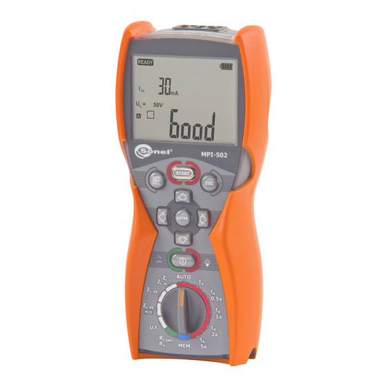
Устройство и работа Sonel MPI-502
На передней панели многофункционального измерителя MPI-502 расположены гнёзда для подключения измерительных проводов, поворотный позиционный переключатель (для задания режимов работы), жидкокристаллический цифровой дисплей и разъёмы для подключения токовых клещей.
|
Схема измерения сопротивления заземления с MPI-502 для сетей TN-C, TN-S и ТТ |
MPI-502 способен измерять сопротивление заземляющего устройства, схема подключения при измерении изображена на рисунке. Где L1, L2, L3 — это фазы, N — нейтраль (нуль), PE – проводник, Rr – сопротивление заземления. В качестве дополнительного источника используется напряжение, взятое с одной из фаз. |
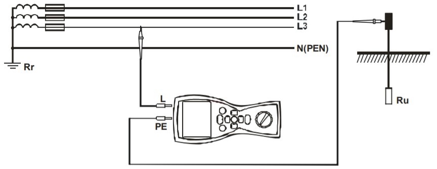
Если прибор обнаружит опасное напряжение на проводнике PE, на дисплее отобразится символ PE (неправильное подключение проводника, замыкание), а также будет издаваться непрерывный звуковой сигнал.
Описание измерителя параметров электробезопасности электроустановок MPI-502:
MPI-502 – портативный измеритель параметров электробезопасности электроустановок от польской компании Sonel. Он комбинирует возможности серий MRP и MZC, комплектуется необходимыми для проведения измерений аксессуарами. Результаты измерений хранит в памяти, может передать их на компьютер для последующей обработки.
Sonel MPI-502 – многофункциональный прибор для всесторонней и высокоточной оценки параметров электрических установок. Он работает в сетях фаза с нулём, фазой, защитным проводом без срабатывания устройств защитного разрыва цепи. Измеритель оценит ток, полное сопротивление петли КЗ установки, параметры УЗО двух типов: A, AC. Определит параметры устройств защитного разрыва электросети типа G с задержкой по времени срабатывания при подаче токов различного номинала: 10 – 500 мА. MPI-502 работает без отключения УЗО при дифференциальном токе выше 30 мА.
Измеритель параметров электробезопасности оснащён встроенной памятью на 10 000 результатов: 10 банков по 99 ячеек, вмещающих различное количество результатов. Информация остаётся в памяти даже после изъятия батареи. Содержимое ячеек можно выводить на дисплей, перемещать между банками, предусмотрена функция очистки памяти. Данные передаются на компьютер через беспроводной модуль Bluetooth или интерфейс OR-1 при помощи фирменного приложения Sonel Reader.
Отличительные особенности:
Измеритель поддерживает режимы подачи номинального дифференциального тока, половины (0,5 I), двукратного (2 I) и пятикратного (5 I) значения для оценки времени, тока отключения УЗО в критических ситуациях. MPI-502 измерит целостность защитного заземления, сопротивление заземляющих или защитных проводов, уведомит об обнаружении опасного напряжения в цепи.
Прибор может работать как:
- Вольтметр – измеряет напряжение номиналом до 500 В при AC.
- Частотомер – диапазон 45 – 65 Гц с разрешением 0,1 Гц.
- Низковольтный омметр – до 2 кОм.
Сферы применения:
Многофункциональный измеритель MPI-502 применяется для всестороннего испытания электрических установок во время обслуживания, периодического осмотра, перед сдачей либо приёмом в эксплуатацию электроустановок или электрических коммуникаций зданий.
Технические характеристики измерителя MPI-502:
| Параметр | Значение |
|---|---|
| Класс изоляции | двойная, согласно PN-EN 61010-1 и IEC 61557 |
| Категория безопасности | IV 300 В (III 600V) согласно PN-EN 61010-1 |
| Степень защиты корпуса согласно PN-EN 60529 | IP67 |
| Питание измерителя | батарейки 4×1,5 В LR6 АА или аккумуляторные батареи NiMH 4×1,5 В LR6 АА |
| Температура хранения | -20…+70 °C |
| Температура рабочая | 0…+50 °C |
| Время до самовыключения | устанавливается в меню прибора |
|
Количество измерений Z, RE или RCD (для щелочных батареек) |
> 3000 (2 измерения / минуту) |
|
Количество измерений RISO или RCONT (для щелочных батареек) |
> 2000 |
| Память результатов измерения | 990 ячеек, 10000 результатов |
| Интерфейс | Беспроводной интерфейс OR-1 (USB) |
| Габариты | 220 х 98 x 58 мм |
| Масса | около 1 кг |
Корпус и питание:
Измеритель питается от четырёх батарей типа AA (алкалиновые LR6 либо никель-металлогидридные HR6). Уровень их заряда отображается в углу сегментного ЖК-дисплея с опциональной подсветкой, которая сохранит читаемость показаний при слабой освещённости.
MPI-502 имеет утончённый к центру корпус. Такой дизайн улучшает надёжность и удобство хвата. Полимерный чехол смягчает удары при падении устройства. Корпус полностью защищён от проникновения пыли, выдерживает кратковременное погружение в воду (до 1 м), но боится конденсата, повышенной влажности.
Ремешок с крючком освободит руки оператора во время измерения – позволяет подвесить прибор на крючок, переносить его на поясе или запястье
Комплект поставки MPI-502:
- Измеритель параметров электробезопасности электроустановок MPI-502
- Адаптер WS-05 с сетевой вилкой UNI-SCHUKO
- Зажим «Крокодил» изолированный красный K02
- Зонд острый с разъемом «банан» голубой
- Зонд острый с разъемом «банан» красный
- Крепеж «Свободные руки»
- Провод измерительный 1,2 м с разъемами «банан» голубой
- Провод измерительный 1,2 м с разъемами «банан» желтый
- Провод измерительный 1,2 м с разъемами «банан» красный
- Ремень для переноски прибора
- Футляр М6