-
Contents
-
Table of Contents
-
Bookmarks
Quick Links
Related Manuals for Sonel MPI-530-IT
Summary of Contents for Sonel MPI-530-IT
-
Page 3
OPERATING MANUAL METER FOR ELECTRICAL INSTALLATION PARAMETERS MPI-530-IT SONEL SA ul. Wokulskiego 11 58-100 Świdnica Version 1.06 07.03.2017… -
Page 4
MPI-530-IT meter is a modern, easy in use and safe measuring device. Please acquaint yourself with this manual in order to avoid measuring errors and prevent possible problems in operation of the me- ter. -
Page 5: Table Of Contents
Measurement of resistance to earth using 4p method……..32 3.5.3 Measurement of resistance to earth using 3p + clamps method ….36 3.5.4 Measurement of resistance to earth using double clamp method ….40 3.5.5 Measuring soil resistivity …………….44 OPERATING MANUAL MPI-530-IT version 1.06…
-
Page 6
….104 OUT AND CHANGE OF CODE FOR LUETOOTH CONNECTIONS POWER SUPPLY OF THE METER …………..106 …………106 ONITORING THE POWER SUPPLY VOLTAGE ) ……….. 106 EPLACING BATTERIES RECHARGEABLE BATTERIES …………… 107 HARGING RECHARGEABLE BATTERIES OPERATING MANUAL MPI-530-IT version 1.06… -
Page 7
………………124 PTIONAL ACCESSORIES 11.2.1 Clamps C-3 ………………..127 11.2.2 Clamps C-6 ………………..129 11.2.3 Clamps F-1, F-2, F-3 …………….. 130 11.2.4 Clamps N-1 ………………..131 POSITIONS OF THE METER’S COVER …………132 MANUFACTURER ………………… 132 OPERATING MANUAL MPI-530-IT version 1.06… -
Page 8: Safety
1 Safety MPI-530-IT meter is designed for performing check tests of protection against electric shock in AC mains systems. The meter is used for making measurements and providing results to determine safety of electrical installations. Therefore, in order to provide conditions for correct operation and accuracy of obtained results, the following recommendations must be observed: …
-
Page 9: Menu
The main menu contains the following items: Wireless transmission Measurement Settings Meter Settings Language selection Information about manufacturer to select desired position. Enter a selected option by pressing ENTER. Wireless transmission See section 5.3. OPERATING MANUAL MPI-530-IT version 1.06…
-
Page 10: Measurement Settings
Only the measurement conducted with a properly selected frequency of measuring signal will ensure optimum filtration of interferences. The meter is designed for filtration of interferences generated by 50 Hz and 60 Hz networks. OPERATING MANUAL MPI-530-IT version 1.06…
-
Page 11: Main Result Of Fault Loop Impedance Measurement
ENTER to confirm your se- lection. 2.2.3 Measurement settings The setting enables activation/deactivation of the field displaying measurement settings. Use to display or hide the field with measurement settings and press ENTER. OPERATING MANUAL MPI-530-IT version 1.06…
-
Page 12: Rcd Auto Measurement Mode
RCD (AC, A, B). 2.2.5 Cell autoincrementing to select automatic or manual in- crementing of field number after entering it to the memory (automatic incrementing is deac- tivated), press ENTER to approve the selec- tion. OPERATING MANUAL MPI-530-IT version 1.06…
-
Page 13: Resistivity Measurement Settings
2.2.6 Resistivity measurement settings to select length unit and result unit, press ENTER to mark your choice. Press F4 to approve the selection. 2.2.7 Calibration of C-3 clamps OPERATING MANUAL MPI-530-IT version 1.06…
-
Page 14: Setting Limits
Meter Settings The option of Meter Settings consists of: LCD contrast LCD Backlight Automatic shut-off Date and time Key sounds Factory (default) settings Updating the meter Wireless communication OPERATING MANUAL MPI-530-IT version 1.06…
-
Page 15: Lcd Contrast
ENTER to edit select- ed option. 2.3.1 LCD contrast to adjust con- trast; press ENTER to confirm. OPERATING MANUAL MPI-530-IT version 1.06…
-
Page 16: Lcd Backlight
LCD Backlight shut-off and press ENTER to confirm. 2.3.3 Automatic shut-off (Auto-OFF) The setting defines the shut-off time of idle meter. to set Auto-OFF time and press ENTER to confirm. OPERATING MANUAL MPI-530-IT version 1.06…
-
Page 17: Date And Time
When required settings are made, press ENTER. 2.3.5 Key sounds buttons to switch-off sound sig- nals assigned to push buttons. Note: — Warning sound signals: U>440V, U>50V, Rbeep, PE!, cannot be switched-off, they remain con- stantly active. OPERATING MANUAL MPI-530-IT version 1.06…
-
Page 18: Factory (Default) Settings
During programming the meter must not be switched off as well as the transmis- sion cable must not be disconnected. Before updating software, download the software from the manufacturer’s website (www.sonel.pl) and install it on your PC, then connect the meter to PC.
-
Page 19: Language Selection
ON/OF and press ENTER to confirm. Language selection to select desired language and press ENTER. Information about manufacturer OPERATING MANUAL MPI-530-IT version 1.06…
-
Page 20: Measurements
This voltage is measured for the frequencies within the range of 45…65 Hz as True RMS. If the measured frequency is outside the specified range, the fol- lowing message is displayed instead of the frequency value: f<45Hz or f>65Hz. Voltage is displayed OPERATING MANUAL MPI-530-IT version 1.06…
-
Page 21: Checking The Correctness Of Pe (Protective Earth) Connections
The above remark does not apply to measurements of fault loop impedance with the use of Z RCD function. L-PE OPERATING MANUAL MPI-530-IT version 1.06…
-
Page 22: Measurement Of Fault Loop Parameters In The L-N And L-L Circuits
L lead length needs to be selected. to select the lead length and press ENTER. In order to set the security param- eters press F2 to set the security parameters and press ENTER. OPERATING MANUAL MPI-530-IT version 1.06…
-
Page 23
— nominal or measured — press F3 to select desired voltage and press ENTER. Measurement Connect test leads according to the drawing a) for measurement in L-N circuit or b) for measurement in L-L circuit OPERATING MANUAL MPI-530-IT version 1.06… -
Page 24
— Minimum interval between successive measurements is 5 seconds. This minimum interval require- ment is controlled by the meter. The next measurement may be performed only when READY! mes- sage appears on the screen. Until the message is displayed — the meter prevents any measurements. OPERATING MANUAL MPI-530-IT version 1.06… -
Page 25: Measurement Of Fault Loop Parameters In The L-Pe Circuit
ENTER. In order to set the security param- eters press F2 to set the security parameters and press ENTER. Measurement Connect test leads according to one of the following drawings. OPERATING MANUAL MPI-530-IT version 1.06…
-
Page 26
— prospective short- circuit current R, X , f — additional L-PE results. The result is displayed on the screen for 20 s. The result can be recalled by pressing ENTER push-button. OPERATING MANUAL MPI-530-IT version 1.06… -
Page 27: Measurement Of Fault Loop Impedance In L-Pe Circuit Protected With A Residual Current Device (Rcd)
ENTER. In order to set the security param- eters press F2 to set the security parameters and press ENTER. Measurement Connect test leads according to one of the drawings. OPERATING MANUAL MPI-530-IT version 1.06…
-
Page 28: Prospective Short-Circuit Current
If the voltage of the network being tested is outside the tolerance range, the meter will not be able to determine a proper rated voltage for the short-circuit current calculation. In such a case, horizontal OPERATING MANUAL MPI-530-IT version 1.06…
-
Page 29: Measurements In It Networks
2.2.1. WARNING: When IT network type (IT system) is chosen, touch electrode on the me- ter is disabled. Connection of the meter to installation is show on the drawing below. OPERATING MANUAL MPI-530-IT version 1.06…
-
Page 30: Measurement Of Resistance To Earth
The tested earth electrode as well as current and voltage electrodes should be located along one line and in the relevant distances, in accordance with the rules of earth measurements. Settings Turn the rotary switch to R position. To select the measurement method press F2 OPERATING MANUAL MPI-530-IT version 1.06…
-
Page 31
3P, confirm by press- ing ENTER. To change the measuring voltage press F1 to select the measuring voltage, confirm by pressing ENTER. In order to set the limit (maximum resistance) press F3 OPERATING MANUAL MPI-530-IT version 1.06… -
Page 32
ENTER to enter the re- sistance value. and ENTER to select unit, confirm by pressing F4 The meter is ready for measure- ment. Value of interference voltage U of the measured object may be read on the display. OPERATING MANUAL MPI-530-IT version 1.06… -
Page 33
In majority of cases the achieved measurement accuracy is satisfactory. However, you should always be aware of the uncertainty included in the measurement. OPERATING MANUAL MPI-530-IT version 1.06… -
Page 34: Measurement Of Resistance To Earth Using 4P Method
ES socket should be connected to the tested earth electrode below E lead. The tested earth electrode as well as current and voltage electrodes should be located along one line and in the relevant distances, in accordance with the rules of earth measurements. OPERATING MANUAL MPI-530-IT version 1.06…
-
Page 35
Settings Set the rotary switch of function selection at R position. To select the measurement method press F2 to select 4P, confirm by press- ing ENTER. To change the measuring voltage, press F1 OPERATING MANUAL MPI-530-IT version 1.06… -
Page 36
ENTER. In order to set the limit (maximum resistance), press F3 and ENTER to enter the re- sistance value. and ENTER to select unit. confirm by pressing F4 OPERATING MANUAL MPI-530-IT version 1.06… -
Page 37
100 V. — Particular attention should be paid to quality of connection between the object being tested and the test lead – the contact area must be free from paint, rust, etc. OPERATING MANUAL MPI-530-IT version 1.06… -
Page 38: Measurement Of Resistance To Earth Using 3P + Clamps Method
The tested earth electrode as well as current and voltage electrodes should be located along one line and in the relevant distances, in accordance with the rules of earth measurements. Clamps should be attached to the tested earth electrode below the connection point of E lead. OPERATING MANUAL MPI-530-IT version 1.06…
-
Page 39
Settings Set the rotary switch of function selection at position. To select the measurement method press F2 to select 3P , confirm by pressing ENTER. To change the measuring voltage, press F1 OPERATING MANUAL MPI-530-IT version 1.06… -
Page 40
ENTER. In order to set the limit (maximum resistance), press and ENTER to enter the re- sistance value. and ENTER to select unit, confirm by pressing F4 OPERATING MANUAL MPI-530-IT version 1.06… -
Page 41
24 V. Voltage of interferences is measured up to the level of 100 V, but above 50 V it is signalled as dangerous. The meter must not be connected to voltages exceeding 100 V. OPERATING MANUAL MPI-530-IT version 1.06… -
Page 42: Measurement Of Resistance To Earth Using Double Clamp Method
3.5.4 Measurement of resistance to earth using double clamp method The double-clamp measurement may be applied where there is no possibility to use electrodes driven into the ground. ATTENTION! The double-clamp method may be only for multiple earthing measurements. OPERATING MANUAL MPI-530-IT version 1.06…
-
Page 43
Set the rotary switch of function selection at R posi- tion. To select the measurement method, F2 to select 1 2, confirm by pressing ENTER. In order to set the limit (maximum resistance) press F3 OPERATING MANUAL MPI-530-IT version 1.06… -
Page 44
ENTER to enter the re- sistance value. and ENTER to select unit, confirm by pressing F4 The meter is ready for measure- ment. The display shows the value of the leakage current flowing through the clamps. OPERATING MANUAL MPI-530-IT version 1.06… -
Page 45
Voltage at test terminals is higher than 24 V but lower than 50 V, measurement is blocked. The interfering signal (noise signal) is too high — the NOISE! measurement result may be affected by additional uncer- tainty. OPERATING MANUAL MPI-530-IT version 1.06… -
Page 46: Measuring Soil Resistivity
Four probes driven into the ground along one line and in equal distances must be connected as shown in the picture above. Settings Set the rotary switch of function selection at R posi- tion. To select the resistivity measurement, press F2 to select Resistivity, confirm by pressing ENTER. OPERATING MANUAL MPI-530-IT version 1.06…
-
Page 47
To change the measuring voltage, press F1 select the measuring voltage, confirm by pressing ENTER. In order to set the limit (maximum allowable re- sistance), press F3 and ENTER to enter the al- lowed maximum value of resistivity. OPERATING MANUAL MPI-530-IT version 1.06… -
Page 48
The meter is ready for measure- ment. Value of interference voltage U of the measured object may be read on the display. Measurement Press START, to enter into the mode of setting the distance between the probes. OPERATING MANUAL MPI-530-IT version 1.06… -
Page 49
Check also the test leads for possible insulation damage and for corroded or loosened connection between the banana plug and the test lead. In majority of cases the achieved measure- ment accuracy is satisfactory. However, you should always be aware of the uncertainty included in the measurement. OPERATING MANUAL MPI-530-IT version 1.06… -
Page 50: Measurement Of Rcd Parameters
Set the rotary switch of function selection at position. Press F1 to enter I n selection mode. Press F2 to enter the selection mode for current waveform. Press F3 to enter RCD type selection mode. OPERATING MANUAL MPI-530-IT version 1.06…
-
Page 51
Press F1 to enter U selection mode. Press F2 and move to selection of measurement mode. to select desired position and press ENTER to confirm. Measurement Connect the meter to the installation according to the drawing. OPERATING MANUAL MPI-530-IT version 1.06… -
Page 52
Lack of neutral lead that is necessary for I n constant and Δ No U pulsed with direct current offset The remaining information is the same as for fault loop measurement (first 7 positions in the table of section 3.4.1). OPERATING MANUAL MPI-530-IT version 1.06… -
Page 53: Measurement Of Rcd Disconnection Time
Press F1 to enter U selection mode. Press F2 to enter RCD type selection mode. Press F3 and move to selection of measurement mode. to select a suitable position and press ENTER to confirm. OPERATING MANUAL MPI-530-IT version 1.06…
-
Page 54: Automatic Measurement Of Rcd Parameters
), disconnection current ), contact voltage (U ) and resistance-to-earth (R ). Additionally, is is possible to automatically measure loop impedance Z RCD in the manner described in section 3.4.3. In this mode, there is L-PE OPERATING MANUAL MPI-530-IT version 1.06…
-
Page 55
START and switching RCD on after each tripping. MPI-530-IT provides two AUTO modes to be chosen from the main menu: — Full mode: measurement for all current waveforms of a given type of RCD (AC, A, B). -
Page 56
ENTER to confirm. For selecting the security means, use to select the parameter and the use to select its value. Measurement Connect the meter to the installation according to the drawing. OPERATING MANUAL MPI-530-IT version 1.06… -
Page 57
— the whole cycle, upper – Z RCD meas- L-PE urement and RCD parame- ters. Read out the result. Use F3 and F4 to change displayed result groups. OPERATING MANUAL MPI-530-IT version 1.06… -
Page 58
— Store the result in the memory (see sec. 4.2) or press ESC, and display only network voltage and frequency. — Remaining remarks and information are the same as for I and Z measurement. L-PE 3.6.3.2 Standard mode Settings Set the rotary switch of function selection at AUTO position. OPERATING MANUAL MPI-530-IT version 1.06… -
Page 59
U — (only for measurement of Z RCD)). L-PE to select desired position and press ENTER to confirm. For selecting the security means, use to select the parameter and the use to select its value. OPERATING MANUAL MPI-530-IT version 1.06… -
Page 60
(a longer interruption may signify com- pletion of the measurements). Progress of measurement process is shown by pro- gress bars: bottom — the whole cycle, upper – Z RCD meas- L-PE urement and RCD parame- ters. OPERATING MANUAL MPI-530-IT version 1.06… -
Page 61: Measurements In It Networks
Before making measurements, the proper network type (earthing system) shall be set in main menu of the meter, see point 2.2.1. WARNING: When IT network type (IT system) is chosen, touch electrode on the meter is disabled. Connection of the meter to installation is show on the drawings below. OPERATING MANUAL MPI-530-IT version 1.06…
-
Page 62: Measurement Of Insulation Resistance
The way of making measurements of RCD tripping time and current and automatic measure- ments is described in points 3.6.1, 3.6.2 and 3.6.3. Operating voltage range: 95 V … 440 V. Measurement of insulation resistance WARNING: The tested object must not be live. OPERATING MANUAL MPI-530-IT version 1.06…
-
Page 63: Double-Lead Measurement
Set the rotary switch of function selection at R position. To change the measuring voltage press F1 select the measuring voltage, confirm by pressing ENTER. In order to set the limit (minimum resistance), press F3 OPERATING MANUAL MPI-530-IT version 1.06…
-
Page 64
ENTER to select unit, confirm by pressing F4 The meter is ready for measure- ment. Value of interference voltage can be read on the display. Measurement Connect test leads according to the drawing. OPERATING MANUAL MPI-530-IT version 1.06… -
Page 65
View of the screen during measurement performed with the use of ENTER- push-button. Read out the result. Note: During measurements of insulation resistance, dangerous voltage up to 1 kV occurs at the ends of test leads of MPI-530-IT. OPERATING MANUAL MPI-530-IT version 1.06… -
Page 66: Measurements By Means Of Leads With Uni-Schuko Outlet Plug (Ws-03 And Ws-04)
Settings Set the rotary switch of function selection at position. Connect WS-03 lead or WS-04 lead with UNI-Schuko outlet plug. The meter detects this fact auto- matically and changes the appear- ance of the screen. OPERATING MANUAL MPI-530-IT version 1.06…
-
Page 67
Note: (L+N)(PE) mode causes the shorting of L and N wires in the tested socket. to enter the second group of parameters. Press F3 to set the minimal resistance. and ENTER to enter the re- sistance value. OPERATING MANUAL MPI-530-IT version 1.06… -
Page 68
View of the screen during measurement. The display shows the symbol of the resistance being measured and the progress bar of this meas- urement. The bottom progress bar shows % of progress of to- tal measurement. OPERATING MANUAL MPI-530-IT version 1.06… -
Page 69: Measurements With Autoiso-1000C Adapter
(3-, 4- or 5-wire lead). Press F3 push-button and move to selection of a sin- gle measurement time. to select desired position and press ENTER to confirm. OPERATING MANUAL MPI-530-IT version 1.06…
-
Page 70
Press F3 to set the minimal resistance. and ENTER to enter the re- sistance value. and ENTER to select unit, confirm by pressing F4 OPERATING MANUAL MPI-530-IT version 1.06… -
Page 71
If any of the voltages exceeds allowable values, the sym- bol of this voltage is displayed with «!» (e.g. U !) and N-PE the measurement is interrupted. Read out the results. Groups of results displayed are changed by means of F3 and F4 push-buttons. OPERATING MANUAL MPI-530-IT version 1.06… -
Page 72: Low-Voltage Measurement Of Resistance
±200 mA current Settings Set the rotary switch of function selection at position. ±200mA Press F1 and move to the selection of the measurement mode. ±200mA, con- to select R CONT firm by pressing ENTER. OPERATING MANUAL MPI-530-IT version 1.06…
-
Page 73
Press F3 to set the maximum resistance. and ENTER to enter the resistance value. Confirm by pressing OPERATING MANUAL MPI-530-IT version 1.06… -
Page 74
START. Note: ATTENTION! When “Voltage on object” message is displayed, the object tested is live. The measurement is blocked. The meter must be immediately disconnected from the object. OPERATING MANUAL MPI-530-IT version 1.06… -
Page 75: Measurement Of Resistance
3.8.2 Measurement of resistance Settings Set the rotary switch of function selection at R position. ±200 mA Press F1 push-button and move to selection of measurement mode. to select R , confirm by press- ing ENTER. OPERATING MANUAL MPI-530-IT version 1.06…
-
Page 76: Compensation Of Test Leads Resistance
In order to eliminate the impact of the resistance of test leads on measurement result, the com- pensation (autozeroing) of resistance may be performed. For this purpose, R functions ±200mA have AUTOZERO sub-function. Press F2 Follow the instructions displayed on the screen. OPERATING MANUAL MPI-530-IT version 1.06…
-
Page 77: Checking Sequence Of Phases
In order to remove the compensation of the leads resistance (return to default calibration), perform the above-mentioned activities with test leads open. Checking sequence of phases Settings Set the rotary switch of function selection at Press F1 to select PHASE SEQUENCE, confirm by pressing ENTER. OPERATING MANUAL MPI-530-IT version 1.06…
-
Page 78
Connect the meter to the installation according to the drawing. The arrow rotates Phase-to-phase clockwise: voltages. correct sequence of phases, Signalling arrow rotates coun- the presence ter-clockwise: the of individual phase sequence is phases. incorrect. OPERATING MANUAL MPI-530-IT version 1.06… -
Page 79: Checking The Motor Rotation Direction
3.10 Checking the motor rotation direction Settings Set the rotary switch of function selection at Press F1 to select MOTOR ROTATION, confirm by pressing ENTER. Measurement Connect the meter to the motor according to the drawing. OPERATING MANUAL MPI-530-IT version 1.06…
-
Page 80: Light Measurements
Do not move the test leads during the test. 3.11 Light measurements Settings Set the rotary switch of function selection at Measurement Connect the optical probe. Instrument enters the light measurement mode. OPERATING MANUAL MPI-530-IT version 1.06…
-
Page 81
Settings Connecting the probe after F1 pressed..use to select LUXMETER, con- firm by pressing ENTER. Press F3 to set the minimum illumination. OPERATING MANUAL MPI-530-IT version 1.06… -
Page 82: Recorder. Measurement And Recording Of Current, Voltage, Cosφ, Pf Factor, Harmonics And Thd
After correct location of the probe — read out the result. 3.12 Recorder. Measurement and recording of current, voltage, cosφ, PF factor, harmonics and THD Settings Set the rotary switch of function selec- tion at LOGGER position. OPERATING MANUAL MPI-530-IT version 1.06…
-
Page 83
%] from selected nominal value. Press F1 , to select the parameters to be recorded. to select the parameter set for recording, press ENTER to approve. Press F2 , to set the sampling time and number of samples. OPERATING MANUAL MPI-530-IT version 1.06… -
Page 84
Press F3 to enter the selection of clamp type. to select the type of clamps, press ENTER to approve. Measurement Connect the device according to the drawing (example of measurement on a motor). OPERATING MANUAL MPI-530-IT version 1.06… -
Page 85
Groups of results displayed are changed by means of F3 and F4 push-buttons. OPERATING MANUAL MPI-530-IT version 1.06… -
Page 86
When displaying harmonics, use to select the number of the harmonic, with the value dis- played on the right side of the screen. OPERATING MANUAL MPI-530-IT version 1.06… -
Page 87: Memory Of Measurement Results
10000 names of these points, 999 names for objects, 999 descriptions of sub-objects and remember the layout created for these objects. Additionally the memory has a space for the list of names (selection lists) extended up to 99 entries. OPERATING MANUAL MPI-530-IT version 1.06…
-
Page 88: The Appearance Of Main Windows In The Measurement Recording Mode
Symbol of the measuring point and the number of such points (for this sub-object) Sub-object containing more sub-objects Sub-object symbol on a grey back- ground Connector (appears when the cursor is over the icon.) OPERATING MANUAL MPI-530-IT version 1.06…
-
Page 89
— Cells unsaved are not available. — It is recommended to delete the memory after reading the data or before performing a new series of measurements that may be stored into the same memory cells as the previous ones. OPERATING MANUAL MPI-530-IT version 1.06… -
Page 90: Storing The Measurement Results Data In The Memory
A cell reserved for a given type of measurement. In order to select a measurement point (cell), use Press ENTER, to save the result in the memory or ESC, to return to displaying the memory structure. OPERATING MANUAL MPI-530-IT version 1.06…
-
Page 91: Extending The Memory Structure
RCD or a different I current are stored, the results concerning a given RCD that have been stored n previously will be lost. 4.2.2 Extending the memory structure Press ESC to start creating the objects. OPERATING MANUAL MPI-530-IT version 1.06…
-
Page 92
Client 1. to move to another client (1 — 10) . Press F1 to edit client data. to set the cursor on each item and press ENTER to start the ed- iting . OPERATING MANUAL MPI-530-IT version 1.06… -
Page 93
Enter the name of the object in the same way as for the customer data. You may use the list of proposed names that is available after pressing F1 OPERATING MANUAL MPI-530-IT version 1.06… -
Page 94
F2 deletes the items. Press F4 to approve the name that appears on the screen. Press ENTER, go to the measurement point. Press F1 to enter the editing of the measuring point name. OPERATING MANUAL MPI-530-IT version 1.06… -
Page 95
After entering the memory, the user may extend its structure by adding new objects and sub- objects as needed. To add a new object, press F4 To add a new sub-object, set the cursor on the chosen object and press F3 OPERATING MANUAL MPI-530-IT version 1.06… -
Page 96: Browsing And Editing The Memory
— The name of an object, sub-object or measurement is possible in memory browse mode or after en- tering entry into the memory after a measurement. Browsing and editing the memory Set the rotary switch of function selection at MEMposition. to select «MEMORY BROWSE AND EDIT”. OPERATING MANUAL MPI-530-IT version 1.06…
-
Page 97
Press F2 to delete a chosen object (sub- object) with all its results. After setting the cursor on the client, use to move to next clients. After selecting desired object (sub-object) press ENTER. OPERATING MANUAL MPI-530-IT version 1.06… -
Page 98: Browsing The Recorder Memory
Press F3 and F4 to display all individual types of results for a given point. Browsing the recorder memory. Set the rotary switch of function selection at MEMposition. to select «LOGGER MEMORY BROWSE». Press ENTER push-button. OPERATING MANUAL MPI-530-IT version 1.06…
-
Page 99
Press F1 to delete a chosen measurement with all its results. Press F3 and F4 to display all individual results for a given measurement. OPERATING MANUAL MPI-530-IT version 1.06… -
Page 100
Statistical values of voltage and current. Press F3 and F4 to display individual results for a given rec- ord. Number of the screen with results / number of all screens with results. Statistical values of power and THD. OPERATING MANUAL MPI-530-IT version 1.06… -
Page 101
Now you can choose successive samples by using and do the same during browsing through next screens. When displaying harmonics, use to select the harmonic that you want to have expressed in numbers on the right side of the screen. OPERATING MANUAL MPI-530-IT version 1.06… -
Page 102: Deleting Memory Data
Deleting memory data Set the rotary switch of function selection at MEM position. to «Memory erasing». Press ENTER push-button. to select deleting the meas- urements/recorder memory. Press ENTER- push-button. OPERATING MANUAL MPI-530-IT version 1.06…
-
Page 103: Data Transmission
In order to ensure the communication of the meter with a PC, a USB cable is required or Blue- tooth module and appropriate software supplied with the meter. The software may be used for many devices manufactured by SONEL S.A. which are equipped with the USB interface.
-
Page 104
PIN, even if you change the PIN of the meter. Connection activity is indicated by symbol, displayed near the clock and it may be seen on the list of available devic- es*. From this moment automatic connection is available. OPERATING MANUAL MPI-530-IT version 1.06… -
Page 105: Automatic Connection
«connect» mode. This process is automatic and al- ways takes place, regardless of the measurement function (excluding the case of active connection to a PC via Bluetooth and charger). Automatic connection is indicated by symbol, located near the OPERATING MANUAL MPI-530-IT version 1.06…
-
Page 106: Data Transmission Using Bluetooth Module
3. On a PC enter Bluetooth connectivity mode, select MPI-530-IT device and connect. 4. If the connection was successful, then the meter will display the following screen: 5. Start the software to read /save data (e.g., Sonel Reader, Sonel PE) and proceed in accordance with its instructions.
-
Page 107
ENTER. Read the current PIN, and change it if necessary, confirming introduced change by pressing ENTER. Note: Standard PIN code for Bluetooth transmission is «123». OPERATING MANUAL MPI-530-IT version 1.06… -
Page 108: Power Supply Of The Meter
Replacing batteries (rechargeable batteries) MPI-530 meter is powered from SONEL NiMH rechargeable battery pack. It is also possible to power the meter by using four LR14 batteries. Battery charger is installed inside the meter and cooperates only with the manufacturer’s re- chargeable battery pack.
-
Page 109: Charging Rechargeable Batteries
End of charging. In order to turn the device off, unplug the power charger. Operating mode Messages regarding the process of charging Battery charge status: changing content of the status bar indicates charging. OPERATING MANUAL MPI-530-IT version 1.06…
-
Page 110: General Principles For Using Ni-Mh Rechargeable Batteries
30°C. If the rechargeable batteries are stored for a long time in a high temperature, then the occurring chemical processes may reduce their lifetime. — Rechargeable batteries NiMH usually lasts for 500-1000 charging cycles. These batteries reach their maximum capacity after being formatted (2-3 charge/discharge cycles). OPERATING MANUAL MPI-530-IT version 1.06…
-
Page 111
— Do not charge or use rechargeable batteries in extreme temperatures. Extreme temperatures re- duce the lifetime of batteries and rechargeable batteries. Avoid placing devices powered by re- chargeable batteries in very hot environments. The nominal working temperature must be absolutely observed. OPERATING MANUAL MPI-530-IT version 1.06… -
Page 112: Cleaning And Maintenance
Worn-out electronic equipment should be sent to a collection point in accordance with the law of waste electrical and electronic equipment. Before the equipment is sent to a collection point, do not dismantle any elements. Observe the local regulations concerning disposal of packages and used batteries/rechargeable batteries. OPERATING MANUAL MPI-530-IT version 1.06…
-
Page 113: Technical Specifications
0.01 A 10.0 A…99.9 A 0.1 A (0,1 % Inom + 2 digits) 100 A…999 A 1.00 kA…3.00 kA 0.01 kA = 3000 A * — Additionally take into account the uncertainty of current clamps. OPERATING MANUAL MPI-530-IT version 1.06…
-
Page 114
≥ 1 % U for U current THD-F 0.0 … 999.9 % 5 % * 0.1 % ≥ 1 % I (h = 2…40) for I * — Additionally take into account the uncertainty of current clamps. OPERATING MANUAL MPI-530-IT version 1.06… -
Page 115
(which is used for displaying). As the correct value, consider I current value, displayed by the meter or by firmware. OPERATING MANUAL MPI-530-IT version 1.06… -
Page 116
: 110 V, 115 V, 127 V, 220 V, 230 V, 240 V Operating voltage range: 95 V…270 V Rated mains frequency f : 50 Hz, 60 Hz Operating frequency range: 45 Hz…65 Hz OPERATING MANUAL MPI-530-IT version 1.06… -
Page 117
1000 1000 * — does not apply to U = 110 V, 115 V, 127 V or IT network OPERATING MANUAL MPI-530-IT version 1.06… -
Page 118
n 300 mA 105 mA..420 mA 1 mA 500 mA 175 mA..700 mA measurement may be performed for positive or negative half-periods of forced leakage current test current duration ……. max. 8,8 s OPERATING MANUAL MPI-530-IT version 1.06… -
Page 119
10.0 …99.9 0.1 ±(8 % m.v. + 4 digits) 100 …999 1 1.00 k…1.99 k 0.01 k * — at maximum interference current 1 A Measurement with additional current clamps, OPERATING MANUAL MPI-530-IT version 1.06… -
Page 120
200 …1999 1 Voltage at open terminals: 4…9V Output current < 8 mA Audio signal for measured resistance < 30 ± 50 % Compensation of test leads resistance OPERATING MANUAL MPI-530-IT version 1.06… -
Page 121
Test voltage: 50 V, 100 V, 250 V, 500 V i 1000 V Accuracy of generated voltage (Robc [] 1000*U [V]): -0 % +10 % from the set value Detection of a dangerous voltage before commencing a measurement OPERATING MANUAL MPI-530-IT version 1.06… -
Page 122
Range for LP-10A probe Spectral Range [lx] Resolution [lx] Basic uncertainty uncertainty 0…3,999 0,001 4,00…39,99 0,01 40,0…399,9 (2 % m.v. + 5 digits) f1<2 % 400…3999 4,00 k…39,99 k 0,01 k 40,0 k…399,9 k 0,1 k OPERATING MANUAL MPI-530-IT version 1.06… -
Page 123
EN 60529 …………… IP54 d) power supply of the meter ………………….alkaline batteries 4×1.5 V LR14 (C) or package of rechargeable batteries SONEL NiMH 4.8 V 4.2 e) parameters of AC adapter for the battery charge ……. 100 V…240 V, 50 Hz…60 Hz dimensions ………………288 mm x 223 mm x 75 mm… -
Page 124: Additional Data
0 % for 50 V Temperature 0 °C…35 °C ± 2 digits for 25 V ±(6.5 % + 5 digits) Serial interference voltage Resistance of electrodes 2.5 % Frequency 99 %..101 % f Mains voltage 85 %..110 % U OPERATING MANUAL MPI-530-IT version 1.06…
-
Page 125: Additional Uncertainties According To Iec 61557-6 (Rcd)
[Ω] is a value of resultant resistance of multiply earthing. whereas R 10.2.5 Additional uncertainties according to IEC 61557-6 (RCD) Significant parameter Designation Additional uncertainty Position Supply voltage Temperature 0 °C…35 °C Resistance of electrodes Mains voltage 85 %..110 % U OPERATING MANUAL MPI-530-IT version 1.06…
-
Page 126: List Of Reference Standards
NiMH 4.8 V 4.2 Ah rechargeable battery pack – WAAKU07 11.2 Optional accessories Additionally, the following items that are not included in the scope of standard equipment may be purchased from the manufacturer or the distributors: OPERATING MANUAL MPI-530-IT version 1.06…
-
Page 127
-5 m (10 m 20 m WAPRZ010REBB receiver clamps C-6 WAPRZ020REBB WAADAAGT16P – five-wire version WAADAAGT16C – four-wire version WACEGC3OKR receiver clamps C-3 AGT-16P or C (16A) adapter for three- phase sockets OPERATING MANUAL MPI-530-IT version 1.06… -
Page 128
WAADALP10A – only probe with PS/2 plug WAADAWS06 – only WS-06 adapter with PS/2 WAADAAGT16T socket AGT-16T (16A) adapter for single-phase probe of LP-10A luxmeter with WS-06 plug, industrial sockets class A, resolution from 0,001 lx OPERATING MANUAL MPI-530-IT version 1.06… -
Page 129: Clamps C-3
Clamps C-3 are used to measure AC in electrical systems of low and medium power. As optional accessories for instruments produced by Sonel S.A., they are compatible with earth resistance me- ters of MRU series and multifunctional meters of MPI series.
-
Page 130
……………………. approx. 550g jaws opening distance ………………….53mm g) height of open jaws ………………….139mm h) maximum diameter of tested cable ………………52mm length of clamp cables ………………….1.5 m working temperature ………………..–10C…+55C OPERATING MANUAL MPI-530-IT version 1.06… -
Page 131: Clamps C-6
Clamps C-6 are designed to measure AC currents with frequencies up to 10kHz for range 10mA … 10A. As optional accessories for instruments produced by Sonel S.A., they are compatible with power quality meters of PQM series and multifunctional meters of MPI series.
-
Page 132: Clamps F-1, F-2, F-3
Flexible clamps (Rogowski coil) F-1, F-2 and F-3 are designed to measure AC currents with fre- quencies up to 10kHz for range 1A…3000A. As optional accessories for instruments produced by Sonel S.A., they are compatible with power quality meters of PQM series and with earth resistance meters of MRU series.
-
Page 133: Clamps N-1
EMC requirements acc. to ….. EN 61000-6-3:2008 and EN 61000-6-2:2008 11.2.4 Clamps N-1 Clamps N-1, as optional accessories for instruments produced by Sonel S.A., are compatible with earth resistance meters of MRU series and are designed to be signal transmitting clamps in double- clamp measurements.
-
Page 134: Positions Of The Meter’s Cover
SONEL S.A. ul. Wokulskiego 11 58-100 Świdnica Poland tel. +48 74 858 38 60 fax +48 74 858 38 09 E-mail: export@sonel.pl Web page: www.sonel.pl Note: Service repairs must be performed only by the manufacturer. OPERATING MANUAL MPI-530-IT version 1.06…
This manual is also suitable for:
Mpi-530
Купить в 1 клик
- Наличие
- уточняйте
- Гарантия
- 12
- Самовывоз
-
Тюмень
- Возможна доставка до адреса
-
Способы оплаты
Описание
Характеристики
Комплектация
Стандартная комплектация:
| Количество | Индекс | |
|---|---|---|
| Адаптер WS-03 с сетевой вилкой UNI-SCHUKO и кнопкой «СТАРТ» | 1 | WAADAWS03 |
| Адаптер автомобильный (12В) | 1 | WAPRZLAD12SAM |
| Аккумуляторная батарея NiMH SONEL-07 4,8V | 1 | WAAKU07 |
| Датчик люксметра LP1 с адаптером WS-06 | 1 | WAADALP1KRU |
| Зажим «Крокодил» изолированный жёлтый K02 | 1 | WAKROYE20K02 |
| Зажим «Крокодил» изолированный красный K02 | 1 | WAKRORE20K02 |
| Зарядное устройство для аккумуляторов Z7, модель SYS1319-3012 | 1 | WAZASZ7 |
| Зонд измерительный для забивки в грунт 30 см | 2 | WASONG30 |
| Зонд острый с разъёмом «банан» голубой | 1 | WASONBUOGB1 |
| Зонд острый с разъёмом «банан» красный | 1 | WASONREOGB1 |
| Зонд острый с разъемом «банан» желтый | 1 | WASONYEOGB1 |
| Кабель последовательного интерфейса USB | 1 | WAPRZUSB |
| Клавиатура Bluetooth RUS | 1 | WAADAMKRU |
| Комплект ремней «Свободные руки» | 1 | WAPOZSZEKRU |
| Провод измерительный 1,2 м с разъемами «банан» голубой | 1 | WAPRZ1X2BUBB |
| Провод измерительный 1,2 м с разъемами «банан» желтый | 1 | WAPRZ1X2YEBB |
| Провод измерительный 1,2 м с разъемами «банан» красный | 1 | WAPRZ1X2REBB |
| Провод измерительный 15 м на катушке с разъёмами «банан» голубой | 1 | WAPRZ015BUBBSZ |
| Провод измерительный 30 м на катушке с разъёмами «банан» красный | 1 | WAPRZ030REBBSZ |
Дополнительная комплектация:
| Индекс | |
|---|---|
| Адаптер AGT-16C | WAADAAGT16C |
| Адаптер AGT-16T | WAADAAGT16T |
| Адаптер AGT-32P | WAADAAGT32P |
| Адаптер AGT-32T | WAADAAGT32T |
| Адаптер AGT-63P | WAADAAGT63P |
| Адаптер AGT-16P | WAADAAGT16P |
| Адаптер AGT-32C | WAADAAGT32C |
| Адаптер AutoISO-1000C | WAADAAISO10C |
| Адаптер для тестирования устройств защитного отключения (УЗО) TWR-1J | WAADATWR1J |
| Аккумуляторная батарея NiMH SONEL-07 4,8V | WAAKU07 |
| Беспроводной интерфейс OR-1 (USB) v2 | # |
| Зажим «Крокодил» изолированный голубой K02 | WAKROBU20K02 |
| Зонд острый с разъемом «банан» складной SP-2M | WASONSP2M |
| Клещи гибкие F-1 | WACEGF1OKR |
| Клещи гибкие F-2 | WACEGF2OKR |
| Клещи гибкие F-3 | WACEGF3OKR |
| Клещи измерительные C-3 | WACEGC3OKR |
| Клещи измерительные C-6 | WACEGC6OKR |
| Клещи передающие N-1 | WACEGN1BB |
| Провод измерительный 10 м с разъемами «банан» красный | WAPRZ010REBB |
| Провод измерительный 20 м с разъемами «банан» красный | WAPRZ020REBB |
| Провод измерительный 25 м на катушке с разъемами «банан» красный | WAPRZ025REBBSZ |
| Провод измерительный 50 м на катушке с разъемами «банан» желтый | WAPRZ050YEBBSZ |
| Программа автоматического формирования протоколов испытаний электроустановок «СОНЭЛ Протоколы 2.0» | # |
| Соединитель электрический — адаптер AC-16 | WAADAAC16 |
| Футляр для двух зондов 80 см | WAFUTL3 |
Файлы

Оформить заказ
Экспертные мнения
Экспертные мнения
Купить MPI-530-IT Измеритель параметров электробезопасности электроустановок в Тюмени легко — просто позвоните по телефону:: 8-800-551-11-01
Описание измерителя параметров электробезопасности электроустановок MPI-530:
Прибор изготавливается польской компанией «SONEL» и представляет собой многофункциональный измеритель, позволяющий оценить техническое состояние электроустановки с высокой точностью и достоверностью.
Оборудование позволяет измерить:
- сопротивление заземляющих устройств;
- уровень напряжения помех;
- сопротивление изоляции электроустановок до 1000 В;
- напряжение переменного тока до 500 В;
- освещённость помещение с использованием адаптера;
- удельное сопротивление грунта;
- сопротивление защитных проводников и контактных соединений.
Для замеров сопротивления изоляции используются сменные адаптеры AutoIso-1000C, WS-03, WS-04.
Межповерочный интервал эксплуатации прибора составляет 12 месяцев.
Отличительные особенности MPI-530:
Измеритель параметров электробезопасности электроустановок MPI-530 позволяет подключаться к компьютеру или ноутбуку с помощью USB-кабеля или беспроводным способом. Прибор имеет встроенный модуль Bluetooth и автоматически выполняет поиск устройств, находящихся в зоне подключения.
Благодаря унифицированности программного обеспечения измеритель MPI-530 способен соединяться и обмениваться данными со всеми устройствами производителя «SONEL».
Разработчик постоянно обновляет программное обеспечение. Для качественной и эффективной работы прибора рекомендуется переустанавливать ПО минимум 1 раз в 3 месяца.
Встроенный модуль памяти даёт возможность сохранять результаты измерений для 10 объектов. Каждый объект хранит информацию для 10 000 точек измерения. Измеренные параметры работы установок можно пересылать по электронной почте, создавать базы данных, строить графические зависимости и анализировать качество работы электроустановок.
Области применения:
Многофункциональный измеритель параметров MPI-530 используется при плановом техническом обслуживании и ревизии электроустановок потребителей. Он применяется наладчиками электрооборудования при приёмо-сдаточных и контрольных испытаниях электроустановок, служит для оценки состояния изоляции токопроводящих кабелей, высоковольтных проводов, измерения токов утечки в электрических сетях.
Технические характеристики измерителя MPI-530:
Измерение напряжения переменного тока (True RMS)
| Диапазоны измерений | Разрешение | Пределы допускаемой основной абсолютной погрешности измерений |
|---|---|---|
| 0…299,9 В | 0,1 В | ± (2% и.в. + 4 е.м.р.) |
| 300…500 В | 1 В | ± (2% и.в. + 2 е.м.р.) |
| Диапазоны измерений | ||
| 0…299,9 В |
Измерение частоты
| Диапазоны измерений | Разрешение | Пределы допускаемой основной абсолютной погрешности измерений |
|---|---|---|
| 45…65 Гц | 0,1 Гц | ±(0.1% и.в. + 1 е.м.р.) |
| Диапазон напряжения | ||
| 50…500 В |
Режим регистратора. Измерение тока (True RMS)
| Диапазон | Разрешение | Основная погрешность* |
|---|---|---|
| С измерительными клещами C-6 | ||
| 0…99,9 мА | 0,1 мА | ± (8 % и.в. + 3 е.м.р.) |
| 100…999 мА | 1 мА | ± (8 % и.в. + 3 е.м.р.) |
| 1,00…9,99 А | 0,01 А | ± (6 % и.в. + 5 е.м.р.) |
| С измерительными клещами C-3 | ||
| 0…99,9 мА | 0,1 мА | ± (8 % и.в. + 3 е.м.р.) |
| 100…мА | 1 мА | ± (8 % и.в. + 3 е.м.р.) |
| 1,00…9,99 А | 0,01 А | ± (6 % и.в. + 5 е.м.р.) |
| 10,0…99,9 А | 0,1 А | ± (5 % и.в. + 5 е.м.р.) |
| 100…999 А | 1 А | ± (5 % и.в. + 5 е.м.р.) |
| С измерительными клещами F-1, F-2, F-3 | ||
| 1…9,99 А | 0,01 А | ± (0,1 % Inom + 2 е.м.р.) |
| 10,0…99,9 А | 0,1 А | ± (0,1 % Inom + 2 е.м.р.) |
| 100…999 A | 1 А | ± (0,1 % Inom + 2 е.м.р.) |
| 1,00…3,00 кA | 0,01 кA | Не нормируется |
Inom = 3000 A * дополнительно следует учесть погрешность токовых клещей.
Измерение активной P, реактивной Q и полной S мощности, а также cos φ.
| Диапазон | Разрешение | Основная погрешность |
|---|---|---|
| Клещи C-6 | ||
| 0…999 ВА | 1 ВА | ± (10%∙Sизм + 3 е.м.р.) |
| 1…5,00 кВА | 0,01 кВА | ± (8%∙Sизм + 5 е.м.р.) |
| Клещи C-3 | ||
| 0…999 ВА | 1 ВА | ± (10%∙Sизм + 5 е.м.р.) |
| 1…9,99 кВА | 0,01 кВА | ± (8%∙Sизм + 5 е.м.р.) |
| 10…99,9 кВА | 0,1 кВА | ± (8%∙Sизм + 5 е.м.р.) |
| 100…500 кВА | 1 кВа | ± (8%∙Sизм + 5 е.м.р.) |
| С измерительными клещами F-1, F-2, F-3 | ||
| 0…999 ВА | 1 ВА | ± (10%∙Sизм + 9 е.м.р.) |
| 1…9,99 кВА | 0,01 кВА | ± (10%∙Sизм + 6 е.м.р.) |
| 10…кВА | 0,1 кВА | ± (10%∙Sизм + 5 е.м.р.) |
| 100…кВА | 1 кВа | ± (10%∙Sизм + 5 е.м.р.) |
| 501…999 кВА | 1 кВа | Не нормируется |
| 1,00…1,50 МВА | 0,01 МВа | Не нормируется |
Измерение гармоник напряжения
| Диапазон | Разрешение | Основная погрешность | |
|---|---|---|---|
| (h=1…15) | 0…299,9 В | 0,1 В | ± (5% UH,hизм + 3 е.м.р.) |
| 300…500 В | 1 В | ||
| (h=16…40) | 0…299,9 В | 0,1 В | |
| 300…500 В | 1 В |
Измерение гармоник тока
| Диапазон | Разрешение | Основная погрешность |
|---|---|---|
| В зависимости от типа используемых клещей (но не более 10 А для C-6 и 1000А для С-3, F-1, F-2, F-3) | В зависимости от диапазона измерения тока | ± 0,1 × IH,h изм |
Коэффициент гармонических составляющих напряжения THDU ( h = 2…40)
| Диапазон | Разрешение | Основная погрешность |
|---|---|---|
| От 0 до 999,9 % (для Uизм > 1%· Unom) | 0,1 % | ± 5% × THDI изм |
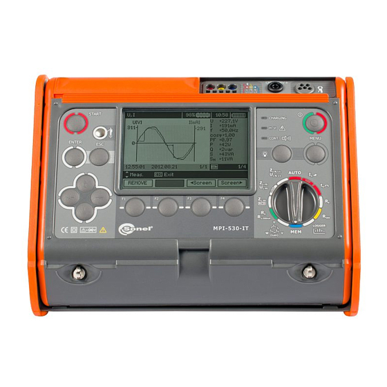
Управление и индикация:
Настройка SONEL MPI-530 выполняется с помощью меню, содержащего параметры беспроводного подключения, настройки измерений, установки и выбор языка. Управление режимами измерений осуществляется поворотным переключателем.
В центре передней панели располагается жидкокристаллический дисплей высокой чёткости, имеющий функцию подсветки. Под дисплеем располагаются функциональные клавиши.
Комплект поставки MPI-530:
- Аккумуляторная батарея NiMH SONEL-07 4,8V — 1 шт.
- Адаптер WS-03 с сетевой вилкой UNI-SCHUKO и кнопкой «СТАРТ» — 1 шт.
- Адаптер автомобильный (12В) — 1 шт.
- Датчик люксметра LP1 с адаптером WS-06 — 1 шт.
- Зажим «Крокодил» изолированный жёлтый K02 — 1 шт.
- Зажим «Крокодил» изолированный красный K02 — 1 шт.
- Зарядное устройство для аккумуляторов Z7 — 1 шт.
- Зонд измерительный для забивки в грунт 30 см — 2 шт.
- Зонд острый с разъёмом «банан» голубой — 1 шт.
- Зонд острый с разъёмом «банан» красный — 1 шт.
- Зонд острый с разъемом «банан» желтый — 1 шт.
- Кабель последовательного интерфейса USB — 1 шт.
- Кабель сетевой WAPRZLAD230CZ — 1 шт.
- Клавиатура Bluetooth RUS — 1 шт.
- Комплект ремней «свободные руки» — 1 шт.
- Провод измерительный 1,2 м с разъемами «банан» голубой — 1 шт.
- Провод измерительный 1,2 м с разъемами «банан» желтый — 1 шт.
- Провод измерительный 1,2 м с разъемами «банан» красный — 1 шт.
- Провод измерительный 15 м на катушке с разъёмами «банан» голубой — 1 шт.
- Провод измерительный 30 м на катушке с разъёмами «банан» красный — 1 шт.
Дополнительная комплектация измерителя MPI-530:
- Адаптер WS-04 — 1 шт.
- Адаптер AutoISO-1000C — 1 шт.
- Измерительные клещи C-3 — 1 шт.
- Измерительные клещи C-6 — 1 шт.
- Измерительные клещи F-1 — 1 шт.
- Измерительные клещи F-2 — 1 шт.
- Измерительные клещи F-3 — 1 шт.
- Передающие клещи N-1 — 1 шт.
- Датчик люксметра LP1 с адаптером WS-06 WACEGN1BB — 1 шт.
- Адаптер для тестирования устройств защитного отключения (УЗО) TWR-1J — 1 шт.
- Отсек для батареек LR14 — 1 шт.
![]()
![]()
MPI-530-IT — измеритель параметров электробезопасности электроустановок
от
305 640
до
315 960 руб.
Описание MPI-530-IT
Измерители MPI-530-IT применяются при наладке и эксплуатационном контроле состояния сети электропитания, а также при приемо-сдаточных и сертификационных испытаниях электроустановок зданий.
Особенности измерителя MPI-530-IT
- измерение полного сопротивления цепи «фаза-нуль», «фаза-фаза», «фаза-защитный проводник»;
- измерение полного сопротивления цепи «фаза-защитный проводник» без срабатывания УЗО;
- вычисление ожидаемого тока короткого замыкания цепи «фаза-нуль», «фаза-фаза», «фаза-защитный проводник»;
- измерение силы тока и времени отключения УЗО типов AC, A, B;
- автоматический режим измерения параметров УЗО;
- измерение параметров УЗО (ток и время отключения) типа AC, A, и B в сетях с изолированной нейтралью (IT);
- измерение сопротивления проводников присоединения к земле и выравнивания потенциалов (металлосвязь);
- измерение сопротивления заземляющих устройств по трёхполюсной схеме (3p);
- измерение сопротивления заземляющих устройств по четырехполюсной схеме (4p);
- измерение сопротивления многократных заземляющих устройств без разрыва цепи заземлителей (3p+токоизмерительные клещи);
- измерение сопротивления заземляющих устройств методом двух клещей;
- измерение удельного сопротивления грунта;
- измерение электрического сопротивления вспомогательных электродов, автоматический расчет дополнительной погрешности;
- измерение сопротивления электроизоляции испытательным напряжением до 1000 В;
- измерение сопротивления электроизоляции с использованием адаптеров WS-03, WS-04, AutoISO-1000C;
- измерение освещенности с использованием адаптера LP1;
- проверка последовательности чередования фаз;
- обновленная структура памяти прибора и передача результатов измерений в компьютер;
Режим регистратора параметров электроэнергии (1 фаза)
- действующего значения напряжения переменного тока;
- частоты переменного тока;
- действующего значения силы переменного тока;
- полной мощности;
- среднеквадратического значения гармонических составляющих напряжения и силы тока;
- суммарного коэффициента гармонических составляющих напряжения и силы тока;
показать все
скрыть
Характеристики MPI-530-IT
Измерение напряжения переменного тока (True RMS)
| Диапазоны измерений | Разрешение | Пределы допускаемой основной абсолютной погрешности измерений |
|---|---|---|
| 0…299,9 В | 0,1 В | ± (2% и.в. + 4 е.м.р.) |
| 300…500 В | 1 В | ± (2% и.в. + 2 е.м.р.) |
Диапазон частоты: 45…65 Гц Измерение частоты
| Диапазоны измерений | Разрешение | Пределы допускаемой основной абсолютной погрешности измерений |
|---|---|---|
| 45…65 Гц | 0,1 Гц | ±(0.1% и.в. + 1 е.м.р.) |
Диапазон напряжения: 50…500 В
Режим регистратора
Измерение тока (True RMS)
| Диапазон | Разрешение | Основная погрешность* |
|---|---|---|
| С измерительными клещами C-6 | ||
| 0…99,9 мА | 0,1 мА | ± (8 % и.в. + 3 е.м.р.) |
| 100…999 мА | 1 мА | |
| 1,00…9,99 А | 0,01 А | ± (6 % и.в. + 5 е.м.р.) |
| С измерительными клещами C-3 | ||
| 0…99,9 мА | 0,1 мА | ± (8 % и.в. + 3 е.м.р.) |
| 100…мА | 1 мА | |
| 1,00…9,99 А | 0,01 А | ± (6 % и.в. + 5 е.м.р.) |
| 10,0…99,9 А | 0,1 А | ± (5 % и.в. + 5 е.м.р.) |
| 100…999 А | 1 А | |
| С измерительными клещами F-1, F-2, F-3 | ||
| 1…9,99 А | 0,01 А | ± (0,1 % Inom + 2 е.м.р.) |
| 10,0…99,9 А | 0,1 А | |
| 100…999 A | 1 А | |
| 1,00…3,00 кA | 0,01 кA | не нормируется |
Inom = 3000 A * дополнительно следует учесть погрешность токовых клещей.
Измерение активной P, реактивной Q и полной S мощности, а также cos φ
| Диапазон | Разрешение | Основная погрешность |
|---|---|---|
| Клещи C-6 | ||
| 0…999 ВА | 1 ВА | ± (10%∙Sизм + 3 е.м.р.) |
| 1…5,00 кВА | 0,01 кВА | ± (8%∙Sизм + 5 е.м.р.) |
| Клещи C-3 | ||
| 0…999 ВА | 1 ВА | ± (10%∙Sизм + 5 е.м.р.) |
| 1…9,99 кВА | 0,01 кВА | ± (8%∙Sизм + 5 е.м.р.) |
| 10…99,9 кВА | 0,1 кВА | ± (8%∙Sизм + 5 е.м.р.) |
| 100…500 кВА | 1 кВа | ± (8%∙Sизм + 5 е.м.р.) |
| С измерительными клещами F-1, F-2, F-3 | ||
| 0…999 ВА | 1 ВА | ± (10%∙Sизм + 9 е.м.р.) |
| 1…9,99 кВА | 0,01 кВА | ± (10%∙Sизм + 6 е.м.р.) |
| 10…кВА | 0,1 кВА | ± (10%∙Sизм + 5 е.м.р.) |
| 100…кВА | 1 кВа | ± (10%∙Sизм + 5 е.м.р.) |
| 501…999 кВА | 1 кВа | не нормируется |
| 1,00…1,50 МВА | 0,01 МВа | не нормируется |
U: от 0 В до 500 В;
I: от 10 мА до 1 кА – С-3;
от 10 мА до 3 кА – F-1, F-2, F-3;
от 10 мА до 10 А – С-6;
f: от 45 Гц до 65 Гц
Таблица сравнения
| Измерение | MPI-502 | MPI-505 | MPI-508 | MPI-520 | MPI-525 | MPI-530 | MPI-530-IT |
|---|---|---|---|---|---|---|---|
| Измерение параметров петли «фаза-нуль» | ZL-N, L-PE, L-L, L-PE RCD | ZL-N, L-PE, L-L, L-PE RCD | ZL-N, L-PE, L-L, L-PE RCD | ZL-N, L-PE, L-L, L-PE RCD | ZL-N, L-PE, L-L, L-PE RCD | ZL-N, L-PE, L-L, L-PE RCD | ZL-N, L-PE, L-L, L-PE RCD |
| Измерение параметров УЗО |
AC, A Режим Auto |
AC, A Режим Auto |
AC, A Режим Auto |
AC, A, B Режим Auto |
AC, A, B Режим Auto |
AC, A, B Режим Auto |
AC, A, B Режим Auto В сетях IT |
| Rcont | + | + | + | + | + | + | + |
| Измерение параметров изоляции |
— |
1000В, 3ГОм |
1000В, 3ГОм AutoISO-1000A |
1000В, 3ГОм AutoISO-1000C |
2500В, 10ГОм Каб, Кпол AutoISO-2500 |
1000В, 10ГОм AutoISO-1000C |
1000В, 10ГОм AutoISO-1000C |
| Измерение параметров заземляющих устройств | — | — | — | 3p | 3p | 3p, 3p+клещи, 4p, ρ, клещи+клещи | 3p, 3p+клещи, 4p, ρ, клещи+клещи |
| U,I,f,Q,P,S,cosφ | — | — | + | + | — |
+, гармоники |
+, гармоники |
| LOGGER | — | — | + | — | — | + | + |
| Чередование фаз | — | + | + | + | + | + | + |
|
Освещенность (люксметр) |
— | — | — | — | — |
+ LP1 |
+ LP1 |
| Память/ПК |
+ OR-1 |
+ USB |
+ USB |
+ USB |
+ USB |
+ USB |
+ USB |
- ZL-N – измерение полного сопротивления петли фаза-ноль и расчет тока короткого замыкания
- ZL-PE — измерение полного сопротивления петли фаза-защитное заземление и расчет тока короткого замыкания
- ZL-L — измерение полного сопротивления петли фаза-фаза и расчет тока короткого замыкания
- ZL-PE RCD — измерение полного сопротивления петли фаза-фаза и расчет тока короткого замыкания без срабатывания УЗО (используется для номиналов 10 мА и 30 мА)
- Режим Auto измерений параметров УЗО позволяет автоматически измерить все необходимые параметры устройства защитного отключения. Прибор автоматически запускает измерение, необходимый список измеряемых параметров устанавливается пользователем самостоятельно в меню прибора.
- Rcont – проверка наличия цепи между заземлителями и заземленными элементами электрооборудования (металлосвязь)
- 3p – измерение сопротивления заземляющего устройства с использованием трехполюсной схемы измерения
- Клещи+клещи – метод двух клещей позволяет проводить измерения сопротивления ЗУ без использования вспомогательных зондов (токовый и потенциальный). Для проведения измерения необходимо двое клещей: передающие клещи N-1 и измерительные клещи C-3
- U – измерение действующего напряжения сети
- I – измерение тока в сети
- f – измерения частоты сети
- Q – измерение реактивной мощности
- P– измерение активной мощности
- S– измерение полной мощности
- cosφ – измерения коэффициента мощности
- LOGGER – регистратор параметров сети (U,I,f,Q,P,S,cosφ) с заданным интервалом времени (от 1 до 99 секунд). Регистрация производится по одной фазе. Для измерения требуется дополнительная покупка токоизмерительных клещей C-3
показать все
скрыть
Выберите модификации MPI-530-IT
Код товара
Информация о товаре
Срок поставки
Количество шт.
Цена
Информация о товаре
MPI-530-IT
Информация о товаре
MPI-530-IT (с поверкой датчика люксметра)
Комплектация MPI-530-IT
- Аккумуляторная батарея NiMH SONEL-07 4,8V (1 шт.)
- Адаптер WS-03 с сетевой вилкой UNI-SCHUKO и кнопкой «СТАРТ» (1 шт.)
- Адаптер автомобильный (12В) (1 шт.)
- Датчик люксметра LP1 с адаптером WS-06 (1 шт.)
- Зажим «Крокодил» изолированный жёлтый K02 (1 шт.)
- Зажим «Крокодил» изолированный красный K02 (1 шт.)
- Зарядное устройство для аккумуляторов Z7 (1 шт.)
- Зонд измерительный для забивки в грунт 30 см (2 шт.)
- Зонд острый с разъёмом «банан» голубой (1 шт.)
- Зонд острый с разъёмом «банан» красный (1 шт.)
- Зонд острый с разъемом «банан» желтый (1 шт.)
- Кабель последовательного интерфейса USB (1 шт.)
- Кабель сетевой (1 шт.)
- Клавиатура Bluetooth RUS (1 шт.)
- Комплект ремней «свободные руки» (1 шт.)
- Провод измерительный 1,2 м с разъемами «банан» голубой (1 шт.)
- Провод измерительный 1,2 м с разъемами «банан» желтый (1 шт.)
- Провод измерительный 1,2 м с разъемами «банан» красный (1 шт.)
- Провод измерительный 15 м на катушке с разъёмами «банан» голубой (1 шт.)
- Провод измерительный 30 м на катушке с разъёмами «банан» красный (1 шт.)
Дополнительная комплектация MPI-530-IT
Документация для MPI-530-IT
Отзывы на MPI-530-IT
По данному товару нет отзывов.
Оставить отзыв
Спасибо за отзыв! Он будет опубликован после прохождения модерации.