-
Contents
-
Table of Contents
-
Bookmarks
Quick Links
Related Manuals for Sonel MRU-120
Summary of Contents for Sonel MRU-120
-
Page 2
MRU-120 – USER MANUAL… -
Page 3
USER MANUAL EARTH RESISTANCE METER MRU-120 SONEL S. A. Wokulskiego 11 58-100 Świdnica Version 2.8 27.07.2021… -
Page 4
The MRU-120 meter is a modern, easy and safe measuring device. Please acquaint yourself with the present manual in order to avoid measuring errors and prevent possible problems related to opera- tion of the meter. MRU-120 – USER MANUAL… -
Page 5: Table Of Contents
6.4 Charging of accumulators ………………34 6.5 Discharging of accumulators ……………… 35 6.6 General principles regarding using Ni-MH accumulators ……..36 7 Cleaning and maintenance …………….37 8 Storage ………………….37 9 Dismantling and disposal …………….37 MRU-120 – USER MANUAL…
-
Page 6
4P, R 3P+C) ….42 11 Accessories ………………..42 11.1 Standard accessories ………………… 42 11.2 Optional accessories ………………..43 12 Positions of the meter’s cover …………..44 13 Manufacturer ………………..44 14 Laboratory services ………………45 MRU-120 – USER MANUAL… -
Page 7: Safety
The MRU-120 meter has been designed for the purpose of measurements of earth connection and equipotential bonding, ground resistivity, as well as clamps current measurements. Any ap- plication that differs from those specified in the present manual may result in a damage to the de- vice and constitute a source of danger for the user.
-
Page 8: Menu
The menu is available at any position of the knob. Press MENU. Using buttons highlight the required position. Press ENTER to select the option. Measurement settings Using buttons highlight the required position. Press ENTER to select the option. MRU-120 – USER MANUAL…
-
Page 9: Mains Frequency
It may be periodically calibrated in order to avoid the influence of the ageing elements upon the resolution of measurements. The procedure of calibration must be realized also after clamp has been replaced. Having read the preliminary infor- mation ENTER. Follow the displayed instructions. MRU-120 – USER MANUAL…
-
Page 10
ERROR: WIRE NOT CONNECTED tions TO H AND E TERMINAL! CALIBRATION ABORTED. PRESS ENTER Incorrect calibra- Check the quality of ERROR: CALIBRATION tion factor the connections COEFFICIENT OUT OF RANGE. and/or replace the CALIBRATION ABORTED. clamp. PRESS ENTER MRU-120 – USER MANUAL… -
Page 11: Earth Resistivity Settings
ENTER to confirm. Meter settings Using buttons select required item. Press ENTER to confirm. 2.2.1 LCD contrast Using the buttons set the contrast value and press ENTER. MRU-120 – USER MANUAL…
-
Page 12: Auto-Off Settings
Visible bar Hidden bar 2.2.4 Date and time Use buttons to select the value to be modified (Day, month, hour, minute). Use buttons to set the value. Once the date and time have been set, press ENTER. MRU-120 – USER MANUAL…
-
Page 13: Battery Discharging
Before you proceed to updating the programme, download from the manufacturer’s web page (www.sonel.pl) the meter programming software, install it in the computer and connect the meter to the computer. Having chosen the Program update in the MENU, proceed in accordance with the instructions displayed by the programme.
-
Page 14: Measurements
The meter is ready for measurement. The auxiliary display shows the value of the interference voltage and its fre- quency. The setting bat shows the mains frequency set in the MENU. Press START In order for the test to commence. MRU-120 – USER MANUAL…
-
Page 15: Calibration Of The Test Leads
(auto-zeroing). In order to do so the measurement function 2P includes the AUTOZERO subfunction. 3.2.1 Auto-zeroing on Turn the meter on. Set the rotational function selector at 2P. Press F1. Follow the displayed instructions. MRU-120 – USER MANUAL…
-
Page 16: Auto-Zeroing Off
Once the auto-zeroing function has been turned off, the legend AUTOZERO will be no long- er displayed. Note: — It is sufficient to realise compensation once for the given test leads. It is also remembered once the meter has been turned off. MRU-120 – USER MANUAL…
-
Page 17: Earth Resistance Measurement With 3-Pole Method (R 3P)
The tested earth electrode as well as the current electrode and voltage electrode should be aligned. The meter is ready for measurement. The auxiliary display shows the value of the interference voltage and its fre- quency. The setting bar shows the mains frequency set in the MENU. MRU-120 – USER MANUAL…
-
Page 18
Read out the result. Current electrode resistance Voltage electrode resistance Additional uncertainty caused by the resistance of the electrodes Displayed, when δ>30% The result is displayer for 20 s. It may be displayed again ENTER is pressed. MRU-120 – USER MANUAL… -
Page 19
The uncertainty of the electrode resistance >30%. (Uncer- LIMIT! tainties calculated on the basis of the measured values) The value of the interfering signal is too high, NOISE! the result may be distorted by additional uncertainty. MRU-120 – USER MANUAL… -
Page 20: Earth Resistance Measurement With 4-Wire Method (R 4P)
Connect the tested earth electrode to the E socket of the meter. Connect the ES socket to the earth electrode below the E cable. The tested earth electrode as well as the current electrode and voltage electrode should be aligned. MRU-120 – USER MANUAL…
-
Page 21
Read out the result. Current electrode resistance Voltage electrode resistance Additional uncertainty caused by the resistance of the electrodes The result is displayer for 20 s. It may be displayed again ENTER is pressed. MRU-120 – USER MANUAL… -
Page 22
The uncertainty of the electrode resistance >30%. (Uncer- LIMIT! tainties calculated on the basis of the measured values) The value of the interfering signal is too high, NOISE! the result may be distorted by additional uncertainty. MRU-120 – USER MANUAL… -
Page 23: Earth Resistance Measurement With 3-Pole Method With Additional Clamp (R E 3P+C)
The auxiliary display shows the value of the interference voltage and its frequen- cy. The setting bar shows the mains fre- quency set in the MENU. Press F1 to ordered to modify the meas- uring voltage. MRU-120 – USER MANUAL…
-
Page 24
— If the resistance of the auxiliary electrodes is too high, then the measurement of the R earth elec- trode will be distorted by additional uncertainty. A particularly high measurement uncertainty is gen- MRU-120 – USER MANUAL… -
Page 25
The uncertainty of the electrode resistance >30%. (Uncer- LIMIT! tainties calculated on the basis of the measured values) Excessive interfering current, the measurement error may >max exceed the basic error MRU-120 – USER MANUAL… -
Page 26: Earth Resistance Measurement With Two-Clamp Method (2C)
Snap the transmission clamp and measurement clamp on the tested earth elec- trode AT east 30 cm from each other. The meter is ready for measurement. Press START In order for the test to com- mence measurement. MRU-120 – USER MANUAL…
-
Page 27
The voltage on the measurement points exceeds 24 V >24V! but lower than 40 V, the measurement is blocked. The value of the interfering signal is too high, NOISE! the result may be distorted by additional uncertainty. MRU-120 – USER MANUAL… -
Page 28: Earth Resistivity Measurement (Ρ)
The meter is ready for measurement. The auxiliary display shows the value of the interference voltage and its fre- quency. The setting bar shows the measurement voltage, mains frequency set in the MENU and the distance be- tween the electrodes. MRU-120 – USER MANUAL…
-
Page 29
ENTER In order to commerce meas- urement. Read out the result. Current electrode resistance Voltage electrode resistance Additional uncertainty caused by the resistance of the electrodes The result is displayer for 20 s. It may be displayed again ENTER is pressed. MRU-120 – USER MANUAL… -
Page 30
The uncertainty of the electrode resistance >30%. (Uncer- LIMIT! tainties calculated on the basis of the measured values) The value of the interfering signal is too high, NOISE! the result may be distorted by additional uncertainty. MRU-120 – USER MANUAL… -
Page 31: Memory
Memory The MRU-120 meters are equipped with a memory whose capacity is 990 results of resistance measurements. Individual measurements are saved in memory cells. The whole memory is divided into 10 banks with 99 cells each. Each result may be saved in a cell of a defined number and in the…
-
Page 32: Memory Erasing
Memory erasing Note: — During the process of memory erasing the progress bar is being displayed. Turn the meter on. Set the rotational function selector at MEM. Using the buttons highlight “Memory erasing”. Press ENTER. MRU-120 – USER MANUAL…
-
Page 33: Memory Browsing
20; cells 21…99 are empty and unavailable. The same principle refers to banks. If the memory is not filled in a continuous manner, then empty measurements and banks are skipped during browsing. MRU-120 – USER MANUAL…
-
Page 34: Data Transmission
USB cable and appropriate software. If the required accessories such have not been purchased along with the meter, then they are available from the manufacturer or an authorised distributor. The accessories may be used in case of many devices manufactured by SONEL S.A. which are equipped with the USB interface.
-
Page 35: Replacement Of Accumulators
Replacement of accumulators The MRU-120 meter is equipped with a package of NiMH accumulators and charger. The package of accumulators is placed in a compartment. The charger is installed inside the meter casing and it may be used solely to charge the original accumulators.
-
Page 36: Fuse Replacement
— As a result of interferences in the network it is possible that the process of charging of accumulators will finish too fast. In the case too short a time of charging is detected it is necessary to remove the plug of the charger and start charging anew. MRU-120 – USER MANUAL…
-
Page 37: Discharging Of Accumulators
In order to guarantee proper functioning of the accumulators (charge indications) and prolong their durability, it is recommended to charge them from zero from time to time. Proceed as follows in order to discharge the accumulators: Press MENU and highlight Meter settings. Press ENTER. MRU-120 – USER MANUAL…
-
Page 38: General Principles Regarding Using Ni-Mh Accumulators
— Do not charge or use accumulators in extreme temperatures. Extreme temperatures reduce the life- time of batteries and accumulators. Avoid placing devices powered from accumulators in very hot en- vironments. The nominal working temperature must be absolutely observed. MRU-120 – USER MANUAL…
-
Page 39: Cleaning And Maintenance
Worn-out electronic equipment should be sent to a collection point in accordance with the law of worn-out electric and electronic equipment. Before the equipment is sent to a collection point, do not dismantle any elements. Observe the local regulations concerning disposal of packages, worn-out batteries and accumula- tors. MRU-120 – USER MANUAL…
-
Page 40: Technical Data
0,1 kΩ Measurement of resistance of auxiliary electrodes R and R Range Resolution Accuracy 0…999 Ω 1 Ω ±(5% (R 1,00…9,99 kΩ 0,01 kΩ 8 digits) but not less than 10% R 10,0…19,9 kΩ 0,1 kΩ MRU-120 – USER MANUAL…
-
Page 41
…………….≤0.5 mA m) power supply of the meter ……accumulator package type SONEL NiMH 4.8 V 3 Ah n) parameters of AC adapter for the battery charge ……100 V…240 V, 50 Hz…60 Hz o) number of measurements for 2P ………. -
Page 42: Additional Data
>1 kΩ lub >1 kΩ lub >1 kΩ and R [Ω], R [Ω] and R [Ω] are values which are displayed by the device. MRU-120 – USER MANUAL…
-
Page 43: Influence Of The Auxiliary Electrodes Upon Earth Resistance Measurements For Function Ρ
R 3P+C The MRU-120 meter may perform a measurement, if the value of the interference current does not exceed 3 A RMS and the frequency complies with the value set in the MENU. Uncertainty [] …
-
Page 44: Additional Uncertainties In Accordance With Iec 61557-4 (2P)
Harness to carry the device, two pieces (short and long) – WAPOZSZEKPL USB cable – WAPRZUSB Accumulator charger (to be used in different countries) – WAZASZ7 Calibration certificate issued by an accredited laboratory User manual MRU-120 – USER MANUAL…
-
Page 45: Optional Accessories
Cable to charge the accumulators from the car lighter socket WAFUTL3 WAAKU07 Case (for auxiliary electrodes 80 cm) Rechargeable battery NiMH 4.8 V 4.2 Ah WAPOJ1 Calibration certificate with accreditation Batteries compartment MRU-120 – USER MANUAL…
-
Page 46: Positions Of The Meter’s Cover
SONEL S.A. Wokulskiego 11 58-100 Świdnica Poland tel. +48 74 858 38 60 fax +48 74 858 38 09 E-mail: export@sonel.pl Web page: www.sonel.pl Attention: Service repairs must be realised solely by the manufacturer. MRU-120 – USER MANUAL…
-
Page 47: Laboratory Services
National Metrological Institute. According to ILAC-G24 „Guidelines for determination of calibration intervals of measuring instru- ments”, SONEL S.A. recommends periodical metrological inspection of the instruments it manufac- tures no less frequently than once every 12 months.
-
Page 48
NOTES MRU-120 – USER MANUAL… -
Page 49
NOTES MRU-120 – USER MANUAL… -
Page 50
NOTES MRU-120 – USER MANUAL… -
Page 52
MRU-120 – USER MANUAL…
Прибор MRU-120 — это многофункциональный портативный измеритель параметров заземляющих устройств и молниезащит. Прибор позволяет измерять параметры ЗУ как классическими методами (3-х или 4-х полюсная схема), так и бесконтактным (метод двух клещей), что особенно актуально в городских условиях, где отсутствует возможность для использования вспомогательных электродов. Прибор обладает хорошими эргономичными показателями и широкими измерительными функциями (в том числе анализ условий, отрицательно влияющих на точность полученных результатов).
Все результаты измерений можно сохранить в памяти прибора с последующей передачей данных на компьютер.
Функциональные возможности измерителя MRU-120
- измерение сопротивления заземляющих устройств по трёхполюсной схеме (3p);
- измерение сопротивления заземляющих устройств по четырехполюсной схеме (4p);
- измерение сопротивления многоэлементных заземляющих устройств без разрыва цепи заземлителей (с применением токоизмерительных клещей С-3);
- измерение сопротивления заземляющих устройств методом двух клещей (С-3 и N-1);
- измерение удельного сопротивления грунта методом Веннера;
- измерение сопротивления контактных соединений заземляющих, защитных проводников и проводников системы уравнивания потенциалов Rcont током ±200 мА разрешением 0,01 Ом;
- измерение напряжения помех;
- измерение сопротивления измерительных зондов;
- автоматический расчет дополнительной погрешности, вызванной сопротивлением измерительных зондов;
- сохранение результатов измерений в память;
- передача данных на ПК по USB или с использованием беспроводного интерфейса OR-1;
- совместим с ПО Sonel Reader и СОНЭЛ Протоколы 2.0.
Работа с измерителем параметров заземляющих устройств MRU-120
Метод измерения сопротивления двумя клещами имеет практическое применение в тех случаях, когда подключение зондов для забивки в грунт невозможно. Измерительные клещи должны быть откалиброваны при первом использовании. Также необходима периодическая калибровка клещей для учёта дополнительной погрешности, связанной со старением элементной базы.
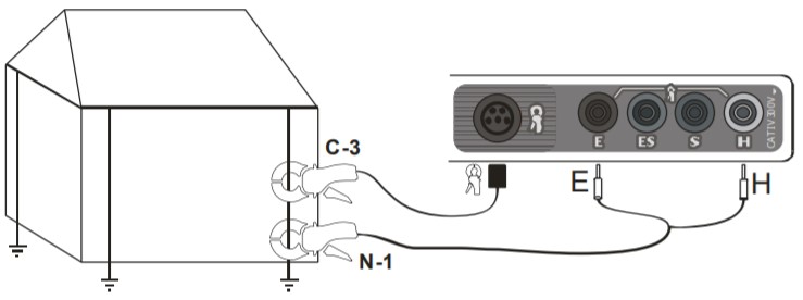
Измерение сопротивления заземления методом двух клещей
На рисунке изображен пример подсоединения клещей при двухклещевом методе замера, где С-3 и N-1 – токовые и передающие клещи соответственно. Передающие клещи N-1 подключаются к разъемам H
и E, при этом измерительные клещи должны быть подключены к стандартному разъёму. Далее замкнуть губки передающих и приёмных клещей на измеряемом заземлении на расстоянии не менее 30 см друг от друга.
Для измерений удельного сопротивления грунта измерители используют сопротивления отдельных электродов системы заземлителя. Расчёт удельного сопротивления методом Веннера основан на условии равного расстояния между измерительными зондами.
110 160 ₽ Выгода — 2 204 ₽
107 956 ₽
Купить в 1 клик
- Наличие
- на складе
- Гарантия
- 12
- Самовывоз
-
Тюмень
- Возможна доставка до адреса
-
Способы оплаты
Описание
Характеристики
Комплектация
Стандартная комплектация:
| Количество | Индекс | |
|---|---|---|
| Адаптер автомобильный (12В) | 1 | WAPRZLAD12SAM |
| Аккумуляторная батарея NiMH SONEL-07 4,8V | 1 | WAAKU07 |
| Зажим «Крокодил» изолированный черный K01 | 1 | WAKROBL20K01 |
| Зарядное устройство для аккумуляторов Z7, модель SYS1319-3012 | 1 | WAZASZ7 |
| Зонд измерительный для забивки в грунт 30 см | 4 | WASONG30 |
| Зонд острый с разъёмом «банан» красный | 1 | WASONREOGB1 |
| Кабель последовательного интерфейса USB | 1 | WAPRZUSB |
| Клещи измерительные C-3 | 1 | WACEGC3OKR |
| Комплект ремней «Свободные руки» | 1 | WAPOZSZEKRU |
| Провод измерительный 1,2 м с разъемами «банан» красный | 1 | WAPRZ1X2REBB |
| Провод измерительный 2,2 м с разъемами «банан» черный | 1 | WAPRZ2X2BLBB |
| Провод измерительный 25 м на катушке с разъёмами «банан» голубой | 1 | WAPRZ025BUBBSZ |
| Провод измерительный 25 м на катушке с разъемами «банан» красный | 1 | WAPRZ025REBBSZ |
| Провод измерительный 50 м на катушке с разъемами «банан» желтый | 1 | WAPRZ050YEBBSZ |
| Футляр L2 | 1 | WAFUTL2 |
Дополнительная комплектация:
| Индекс | |
|---|---|
| Аккумуляторная батарея NiMH SONEL-07 4,8V | WAAKU07 |
| Беспроводной интерфейс OR-1 (USB) | WAADAUSBOR1 |
| Зажим «Крокодил» изолированный красный K02 | WAKRORE20K02 |
| Зажим специальный типа «струбцина» с разъемом «банан» | WAZACIMA1 |
| Зонд измерительный для забивки в грунт 80 см | WASONG80 |
| Катушка для намотки измерительного провода | WAPOZSZP1 |
| Клещи передающие N-1 | WACEGN1BB |
| Комплект измерительных проводов 2 м с разъемами «банан» | WAPRZ002DZBB |
| Отсек для батареек LR14 | WAPOJ1 |
| Провод измерительный 100 м на катушке с разъёмами «банан» желтый | WAPRZ100YEBBSZ |
| Провод измерительный 200 м на катушке с разъёмами «банан» желтый | WAPRZ200YEBBSZ |
| Провод измерительный 75 м на катушке с разъёмами «банан» желтый | WAPRZ075YEBBSZ |
| Программа автоматического формирования протоколов испытаний электроустановок «СОНЭЛ Протоколы 2.0» | # |
| Футляр для двух зондов 80 см | WAFUTL3 |
Файлы

Оформить заказ
Экспертные мнения
Экспертные мнения
Купить MRU-120 Измеритель параметров заземляющих устройств в Тюмени легко — просто позвоните по телефону:: 8-800-551-11-01