- Manuals
- Brands
- MSI Manuals
- Motherboard
- B350 TOMAHAWK
- User manual
-
Contents
-
Table of Contents
-
Troubleshooting
-
Bookmarks
Quick Links
Unpacking
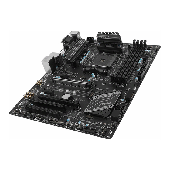
Thank you for buying the MSI
B350 TOMAHAWK
motherboard. Check to make sure
®
your motherboard box contains the following items. If something is missing, contact
your dealer as soon as possible.
Drivers & Utilities
Motherboard User
Disc
Guide
Motherboard
I/O Shield
SATA Cable x2
1
Unpacking
Related Manuals for MSI B350 TOMAHAWK
Summary of Contents for MSI B350 TOMAHAWK
-
Page 1: Unpacking
Unpacking Thank you for buying the MSI B350 TOMAHAWK motherboard. Check to make sure ® your motherboard box contains the following items. If something is missing, contact your dealer as soon as possible. Drivers & Utilities Motherboard User Disc Guide…
-
Page 2: Safety Information
Safety Information The components included in this package are prone to damage from electrostatic discharge (ESD). Please adhere to the following instructions to ensure successful computer assembly. Ensure that all components are securely connected. Loose connections may cause the computer to not recognize a component or fail to start. Hold the motherboard by the edges to avoid touching sensitive components.
-
Page 3: Quick Start
Quick Start Preparing Tools and Components AM4 CPU ® Thermal Paste CPU Fan DDR4 Memory Power Supply Unit Chassis SATA Hard Disk Drive Graphics Card SATA DVD Drive A Package of Screws Phillips Screwdriver Quick Start…
-
Page 4: Installing A Processor
Installing a Processor https://youtu.be/Xv89nhFk1vc Quick Start…
-
Page 5: Installing Ddr4 Memory
Installing DDR4 memory http://youtu.be/T03aDrJPyQs DIMMB2 DIMMB2 DIMMB1 DIMMA2 DIMMA2 DIMMA2 DIMMA1 Quick Start…
-
Page 6: Connecting The Front Panel Header
Connecting the Front Panel Header http://youtu.be/DPELIdVNZUI HDD LED + Power LED + HDD LED — Power LED — Reset Switch Power Switch Reset Switch Power Switch JFP1 Reserved No Pin JFP1 HDD LED — HDD LED HDD LED + POWER LED — POWER LED POWER LED + Quick Start…
-
Page 7: Installing The Motherboard
Installing the Motherboard Quick Start…
-
Page 8: Installing Sata Drives
Installing SATA Drives http://youtu.be/RZsMpqxythc Quick Start…
-
Page 9: Installing A Graphics Card
Installing a Graphics Card http://youtu.be/mG0GZpr9w_A Quick Start…
-
Page 10: Connecting Peripheral Devices
Connecting Peripheral Devices Quick Start…
-
Page 11: Connecting The Power Connectors
Connecting the Power Connectors http://youtu.be/gkDYyR_83I4 ATX_PWR1 CPU_PWR1 Quick Start…
-
Page 12: Power On
Power On Quick Start…
-
Page 13: Table Of Contents
Contents Unpacking ………………….1 Safety Information ………………..2 Quick Start ………………….3 Preparing Tools and Components …………….3 Installing a Processor ………………… 4 Installing DDR4 memory ………………5 Connecting the Front Panel Header …………… 6 Installing the Motherboard ………………7 Installing SATA Drives…………………
-
Page 14
LIVE UPDATE 6 …………………. 56 COMMAND CENTER ………………… 58 GAMING APP ………………….62 RAMDISK………………….. 67 X-BOOST ………………….. 68 MSI SMART TOOL ………………..70 GAMING LAN MANAGER ………………72 Nahimic 2 ………………….75 XSplit Gamecaster V2 ………………. 79 SteelSeries Engine 3 ……………….. 83 CPU-Z…………………… -
Page 15: Specifications
Dual channel memory architecture * 7th Gen A-series/ Athlon processors support a maximum of DDR4 2400 Mhz. Please refer www.msi.com for more information on compatible memory. 1x PCIe 3.0 x16 slot (PCI_E2) Supports x 16 speed with RYZEN Series Processors ƒ…
-
Page 16
Continued from previous page B350 Chipset ® 4x USB 3.1 Gen1 (SuperSpeed USB) ports available ƒ through the internal USB 3.1 Gen1 connectors 6x USB 2.0 (High-speed USB) ports (2 Type-A ports on ƒ the back panel, 4 ports available through the internal USB 2.0 connectors) processor ®… -
Page 17
12 in. x 9.6 in. (30.4 cm x 24.3 cm) 1x 128 Mb flash BIOS Features UEFI AMI BIOS Multi-language Drivers SUPER CHARGER COMMAND CENTER LIVE UPDATE 6 MSI SMART TOOL DRAGON EYE GAMING APP X-BOOST Software RAMDISK GAMING LAN MANAGER Nahimic Audio XSplit Gamecaster V2… -
Page 18
7000+ Quality Test VR Ready GAMING HOTKEY GAMING MOUSE Control Click BIOS 5 AMD FreeSync™ Ready AMD OverDriver™ Ready GAMING Certified SteelSeries Certified WTFast* * This offer is valid for a limited period only, for more information please visit www.msi.com Specifications… -
Page 19: Block Diagram
Block Diagram DVI-D HDMI 2 Channel DDR4 Memory PCI Express Bus 4 x USB 3.1 Gen1 1 x M.2 Audio Jacks Realtek NV6795 ALC892 Super I/O P/S2 Mouse / Keyboard PCIe x1 slot PCIe X4 PCIe x1 slot PCI slot PCIe x16 slot (support x4 mode) PCI slot…
-
Page 20: Rear I/O Panel
Rear I/O Panel Audio Ports PS/2 USB 3.1 Gen1 USB 3.1 Gen1 USB 2.0 DVI-D USB 3.1 Gen1 Type-C LAN Port LED Status Table Link/ Activity LED Speed LED Status Description Status Description No link 10 Mbps connection Yellow Linked Green 100 Mbps connection Blinking…
-
Page 21: Realtek Hd Audio Manager
Realtek HD Audio Manager After installing the Realtek HD Audio driver, the Realtek HD Audio Manager icon will appear in the system tray. Double click on the icon to launch. Device Selection Advanced Settings Jack Status Application Enhancement Main Volume Connector Strings Profiles…
-
Page 22
Audio jacks to headphone and microphone diagram Audio jacks to stereo speakers diagram AUDIO INPUT Audio jacks to 7.1-channel speakers diagram AUDIO INPUT Rear Front Side Center/ Subwoofer Rear I/O Panel… -
Page 23: Overview Of Components
Overview of Components SYS_FAN1 DIMMA1 DIMMA2 CPU_FAN1 DIMMB1 CPU_PWR1 DIMMB2 CPU Socket PUMP_FAN1 SYS_FAN3 ATX_PWR1 PCI_E1 PCI_E2 JUSB4 M2_1 JBAT1 SATA4 PCI_E3 SATA3 PCI_E4 JCI1 SATA▼1▲2 PCI1 SYS_FAN4 JTPM1 PCI2 JFP2 JFP1 JAUD1 JUSB3 JLED1 JUSB2 SYS_FAN2 JUSB1 JCOM1 JLPT1 Overview of Components…
-
Page 24
Component Contents Port Name Port Type Page CPU_FAN1, PUMP_FAN1, Fan Connectors SYS_FAN1~4 CPU_PWR1, ATX_PWR1 Power Connectors CPU Socket AM4 Socket DIMMA1, DIMMA2, DIMMB1, DIMM Slots DIMMB2 JAUD1 Front Audio Connector JBAT1 Clear CMOS (Reset BIOS) Jumper JCI1 Chassis Intrusion Connector JCOM1 Serial Port Connector JFP1, JFP2… -
Page 25: Cpu Socket
This motherboard is designed to support overclocking. Before attempting to overclock, please make sure that all other system components can tolerate overclocking. Any attempt to operate beyond product specifications is not recommended. MSI does not guarantee the damages or risks caused by ®…
-
Page 26: Dimm Slots
Due to AM4 CPU/memory controller official specification limitation, the frequency of memory modules may operate lower than the marked value under the default state. Please refer www.msi.com for more information on compatible memory. Overview of Components…
-
Page 27: Pci_E1~4, Pci1~2: Pcie & Pci Expansion Slots
PCI1: PCI slot PCI2: PCI slot Important If you install a large and heavy graphics card, you need to use a tool such as MSI Gaming Series Graphics Card Bolster to support its weight to prevent deformation of the slot.
-
Page 28: M2_1: M.2 Slot (Key M)
M2_1: M.2 Slot (Key M) Video Demonstration Watch the video to learn how to Install M.2 module. http://youtu.be/JCTFABytrYA Installing M.2 module Remove the screw from the base screw. Remove the base screw. Tighten the base screw into the hole of the distance to the M.2 slot as the length your M.2 module.
-
Page 29: Sata1~4: Sata 6Gb/S Connectors
SATA1~4: SATA 6Gb/s Connectors These connectors are SATA 6Gb/s interface ports. Each connector can connect to one SATA device. SATA4 SATA3 SATA2 SATA1 Important Please do not fold the SATA cable at a 90-degree angle. Data loss may result during transmission otherwise.
-
Page 30: Cpu_Pwr1, Atx_Pwr1: Power Connectors
CPU_PWR1, ATX_PWR1: Power Connectors These connectors allow you to connect an ATX power supply. CPU_PWR1 Ground +12V Ground +12V Ground +12V Ground +12V +3.3V +3.3V +3.3V -12V Ground Ground PS-ON# Ground Ground Ground ATX_PWR1 Ground Ground PWR OK 5VSB +12V +12V +3.3V Ground…
-
Page 31: Jusb1~2: Usb 2.0 Connectors
JUSB1~2: USB 2.0 Connectors These connectors allow you to connect USB 2.0 ports on the front panel. USB0- USB1- USB0+ USB1+ Ground Ground No Pin Important Note that the VCC and Ground pins must be connected correctly to avoid possible damage.
-
Page 32: Cpu_Fan1, Pump_Fan1, Sys_Fan1~4: Fan Connectors
CPU_FAN1, PUMP_FAN1, SYS_FAN1~4: Fan Connectors Fan connectors can be classified as PWM (Pulse Width Modulation) Mode or DC Mode. PWM Mode fan connectors provide constant 12V output and adjust fan speed with speed control signal. DC Mode fan connectors control fan speed by changing voltage. When you plug a 3-pin (Non-PWM) fan to a fan connector in PWM mode, the fan speed will always maintain at 100%, which might create a lot of noise.
-
Page 33: Jci1: Chassis Intrusion Connector
JCI1: Chassis Intrusion Connector This connector allows you to connect the chassis intrusion switch cable. Normal Trigger the chassis intrusion event (default) Using chassis intrusion detector Connect the JCI1 connector to the chassis intrusion switch/ sensor on the chassis. Close the chassis cover. Go to BIOS >…
-
Page 34: Jfp1, Jfp2: Front Panel Connectors
JFP1, JFP2: Front Panel Connectors These connectors connect to the switches and LEDs on the front panel. JFP1 HDD LED + Power LED + HDD LED — Power LED — Reset Switch Power Switch Reset Switch Power Switch Reserved No Pin Speaker — Buzzer + JFP2…
-
Page 35: Jled1: Rgb Led Strip Connector
JLED1: RGB LED strip connector This connector allows you to connect the extended 5050 RGB LED strips. +12V 5050 LED strip JLED1 Video Demonstration Watch the video to learn how to install 5050 RGB LED strips to RGB LED connector. https://youtu.be/CqNHyADzd2Q Important This connector supports 5050 RGB multi-color LED strips (12V/G/R/B) with the…
-
Page 36: Jbat1: Clear Cmos (Reset Bios) Jumper
JBAT1: Clear CMOS (Reset BIOS) Jumper There is CMOS memory onboard that is external powered from a battery located on the motherboard to save system configuration data. If you want to clear the system configuration, set the jumpers to clear the CMOS memory. Keep Data Clear CMOS/ Reset BIOS…
-
Page 37: Bios Setup
BIOS Setup The default settings offer the optimal performance for system stability in normal conditions. You should always keep the default settings to avoid possible system damage or failure booting unless you are familiar with BIOS. Important BIOS items are continuously update for better system performance. Therefore, the description may be slightly different from the latest BIOS and should be for reference only.
-
Page 38: Resetting Bios
Updating BIOS Updating BIOS with M-FLASH Before updating: Please download the latest BIOS file that matches your motherboard model from MSI website. And then save the BIOS file into the USB flash drive. Updating BIOS: Press Del key to enter the BIOS Setup during POST.
-
Page 39: Ez Mode
EZ Mode At EZ mode, it provides the basic system information and allows you to configure the basic setting. To configure the advanced BIOS settings, please enter the Advanced Mode by pressing the Setup Mode switch or F7 function key. Screenshot Setup Mode switch Search…
-
Page 40
Information display — click on the CPU, Memory, Storage, Fan Info and Help buttons on left side to display related information. Function buttons — enable or disable the LAN Option ROM, HD audio controller, AHCI, RAID, CPU Fan Fail Warning Control and BIOS Log Review by clicking on their respective button. -
Page 41: Advanced Mode
Advanced Mode Press Setup Mode switch or F7 function key can switch between EZ Mode and Advanced Mode in BIOS setup. Screenshot Setup Mode switch Search Language System information GAME BOOST switch Boot device priority bar BIOS menu BIOS menu selection selection Menu display…
-
Page 42: Settings
SETTINGS System Status System Date Sets the system date. Use tab key to switch between date elements. The format is <day> <month> <date> <year>. <day> Day of the week, from Sun to Sat, determined by BIOS. Read-only. <month> The month from Jan. through Dec. <date>…
-
Page 43
fPCI Latency Timer [32] Sets latency timer of PCI interface device. [Options: 32, 64, 96, 128, 160, 192, 224, 248 PCI Bus clocks] ACPI Settings Sets ACPI parameters of onboard power LED behaviors. Press Enter to enter the sub- menu. fPower LED [Blinking] Sets shining behaviors of the onboard Power LED. -
Page 44
fSATA Mode [AHCI Mode] Sets the operation mode of the onboard SATA controller. [AHCI Mode] Specify the AHCI mode for SATA storage devices. AHCI (Advanced Host Controller Interface) offers some advanced features to enhance the speed and performance of SATA storage device, such as Native Command Queuing (NCQ) and hot-plugging. -
Page 45
Super IO Configuration Sets system Super I/O chip parameters including LPT and COM ports. Press Enter to enter the sub-menu. fSerial (COM) Port 0 Configuration Sets detailed configuration of serial(COM) port 0. Press Enter to enter the sub- menu. fSerial (COM) Port 0 [Enabled] Enables or disables serial (COM) port x. -
Page 46
fSystem Power Fault Protection [Disabled] Enables or disables the system to boot up when detecting abnormal voltage input. [Enabled] Protect the system from unexpected power operating and remain the shut down status. [Disabled] Disables this function. Windows OS Configuration Sets Windows detailed configuration and behaviors. Press Enter to enter the sub- menu. -
Page 47
[Enabled] Enables the system to be awakened from the power saving modes when activity or input signal of PCI/ PCIe device is detected. [Disabled] Disables this function. fResume by USB Device [Disabled] Disables or enables system wake up from S3/S4 by USB device. [Enabled] Enables the system to be awakened from sleep state when activity of USB device is detected. -
Page 48: Security
AUTO CLR_CMOS [Disabled] Enables or disables the CMOS data to be resumed automatically when the system cannot boot to OS and reboot repeatedly. Boot Mode Select [LEGACY+UEFI] Sets the system boot mode from legacy or UEFI architecture depending on OS installation requirement.
-
Page 49: Save & Exit
Trusted Computing Sets TPM (Trusted Platform Module) function. fSecurity Device Support [Disabled] Enables or disables the TPM function to build the endorsement key for accessing the system. fAMD fTPM switch [AMD CPU fTPM] Selects TPM device. [AMD CPU fTPM] Select it for AMD Firmware TPM. [AMD CPU fTPM Disabled] Select it for Discrete TPM.
-
Page 50
Important Overclocking your PC manually is only recommended for advanced users. Overclocking is not guaranteed, and if done improperly, it could void your warranty or severely damage your hardware. If you are unfamiliar with overclocking, we advise you to use GAME BOOST function for easy overclocking. -
Page 51
CPU Voltages control [Auto] These options allows you to set the voltages related to CPU. If set to Auto, BIOS will set these voltages automatically or you can set it manually. DRAM/ PROM Voltages control [Auto] These options allows you to set the voltages related to memory. If set to Auto, BIOS will set these voltages automatically or you can set it manually. -
Page 52: M-Flash
M-FLASH provides the way to update BIOS with a USB flash drive. Please download the latest BIOS file that matches your motherboard model from MSI website, save the BIOS file into your USB flash drive. And then follow the steps below to update BIOS.
-
Page 53: Oc Profile
OC PROFILE Overclocking Profile 1/ 2/ 3/ 4/ 5/ 6 Overclocking Profile 1/ 2/ 3/ 4/ 5/ 6 management. Press Enter to enter the sub-menu. fSet Name for Overclocking Profile 1/ 2/ 3/ 4/ 5/ 6 Name the current overclocking profile. fSave Overclocking Profile 1/ 2/ 3/ 4/ 5/ 6 Save the current overclocking profile.
-
Page 54: Hardware Monitor
HARDWARE MONITOR Temperature & Speed Fan Manage Setting Buttons Voltage display Temperature & Speed Shows the current CPU temperature, system temperature and fans’ speeds. Fan Manage PWM — allows you to select the PWM mode for fan operation. ƒ DC — allows you to select the DC mode for fan operation. ƒ…
-
Page 55: Software Description
7/ 10 disc into your optical drive. ® Note: Due to chipset limitation, during the Windows 7 installation process, USB optical drives or USB flash drives are not supported. You can use MSI Smart Tool to install Windows ® Press the Restart button on the computer case.
-
Page 56: Live Update 6
LIVE UPDATE 6 LIVE UPDATE 6 is an application for the MSI system to scan and download the latest ® drivers, BIOS and utilities. With LIVE UPDATE 6, you don’ t need to search the drivers on websites, and don’ t need to know the models of motherboard and graphics cards.
-
Page 57
Select the Live Update tab. Choose Automatic scan, system will automatically scan all the items and search for the latest update files. Or you can choose Manual scan and select the items you wish to scan. Click the Scan button at the bottom. It may take several moments to complete the process. -
Page 58: Command Center
COMMAND CENTER COMMAND CENTER is an user-friendly software and exclusively developed by MSI, helping users to adjust system settings and monitor status under OS. With the help of COMMAND CENTER, making it possible to achieve easier and efficient monitoring process and adjustments than that under BIOS. In addition, the COMMAND CENTER can be a server for mobile remote control application.
-
Page 59
CPU Fan CPU Fan control panel provides Smart mode and Manual Mode. You can switch the control mode by clicking the Smart Mode and Manual Mode buttons on the top of the CPU Fan control panel. Manual Mode — allows you to manually control the CPU fan speed by percentage. -
Page 60
GAME BOOST GAME BOOST provides a specified CPU frequency for overclocking the CPU. Option Buttons — Advanced When click the Advanced button, The Voltage, Fan and DRAM icons will appear. Voltage — allows you to adjust advanced voltage values of CPU and chipset. Fan — allows you to control the system fans speed. -
Page 61
Find the IP address on the SoftAP Management Setting area, and enter the IP address on your MSI COMMAND CENTER APP to link your system. ® Press Refresh on the MSI COMMAND CENTER APP to verify that monitoring and ® OC functions are working properly. -
Page 62: Gaming App
Connect your android device and motherboard to the same local area network. Run MSI GAMING APP APP on your android device. ® Press the Remote Control Setting icon on the MSI GAMING APP APP to find the ® paired device Name you set in the Remote Control Setting panel.
-
Page 63
LED function allows you to control LED lights on your motherboard. ON/OFF LED Area Selection LED ON/OFF — allows you to turn ON/ OFF the LED function. LED Area Selection — separately controls each segment of LEDs on your motherboard and graphics cards. MB Extend LED (optional, controls the extended RGB LED strip. -
Page 64
Eye Rest Eye Rest allows you to optimize the display on your monitor. EyeRest — reduces blue-light of your LED backlit screen, in order to protect your eyes. Gaming — automatically increases contrast ratio of your screen. Movie — automatically increases dynamic contrast ratio of your screen. Customize — allows you to adjust gamma, contrast and color balance for your screen. -
Page 65
Login Keys — provides hotkey login function. ƒ MSI Smart Keys — allows you to define hotkeys for MSI Smart Keys. ƒ Hotkey Manager — allows you to create, edit and delete hotkeys. Current Hotkeys — shows all existing hotkeys. -
Page 66
Mouse Master Mouse Master provides mouse macro function. You can also use it to change DPI of your mouse. DPI Setting Delay Time Default Button Macro Hot Key DPI Hot Key Mouse Action Action List Test Area Edit Buttons Clear Button Load Button Save Button Delay Time — allows you to apply a delay time in mouse macro. -
Page 67: Ramdisk
RAMDISK RAMDISK creates a virtual RAM drive using the available memory in your computer, the performance of the RAMDISK is faster than an SSD and hard drive. RAMDISK allows you to store any temporary information on it. Furthermore, using the RAMDISK will extend your SSD’…
-
Page 68: X-Boost
X-BOOST The MSI X-BOOST allows you to select the system performance mode to meet your current system environment or support faster storage access speed for your external storage or memory cards. Easy In Easy page, you can select one system performance mode to meet the current system environment.
-
Page 69
Setting — enables or disables Run X-BOOST when windows starts. Important Please note that you can only select one mode at a time from Easy or Advance page as MSI X-BOOST function. The improved transfer rate/ access speed will vary with the USB/ storage device. Software Description… -
Page 70: Msi Smart Tool
MSI SMART TOOL MSI SMART TOOL is a convenient tool that can help you to create your Windows installation USB flash drive with USB 3.0 drivers, and it can also create a super RAID. Main menu After installing and activating MSI SMART TOOL, it will display a main menu for you to choose Win7 Smart Tool or Super RAID.
-
Page 71
Important You can also create an installer ISO image file by selecting the ISO destination in Step2, and then burn it onto the DVD. Super RAID This utility allows you to create a Super RAID in Windows system. To create a Super RAID: Use checkboxs to select the disks you want included in your RAID. -
Page 72: Gaming Lan Manager
GAMING LAN MANAGER GAMING LAN MANAGER is an utility for traffic shaping for the Windows 7/ 10. It can keep your internet fast during heavy upload/ download and improve your ping for online games. If your motherboard has a Wi-Fi module, GAMING LAN MANAGER provides virtual access point function for traffic shaping for your mobile devices.
-
Page 73
Speed Testing The speed testing is used to optimize bandwidth usage. To test the Upload and Down- load speed, please follow the steps below: Click the Network Test block in GAMING LAN MANAGER. Click Test Network Speed button. The test takes several minutes to test your network speed. -
Page 74
DRAGON EYE DRAGON EYE allows you to watch game guides, tutorials, live match or tournament stream while gaming. In game, you can use hotkeys to control/adjust the settings of DRAGON EYE. Size Settings Position Settings On / Off Switch Help Transparency Settings Video List Hotkeys Information… -
Page 75: Nahimic 2
HD Audio Recorder2 and Sound Tracker. Installation and Update Nahimic 2 is included in the audio driver. If you need to install it or update it, please use the Driver Disc with your motherboard or download the driver from MSI’ s official website. Audio Tab From this tab, you can access all of Nahimic 2’…
-
Page 76
Smart Loudness — maintains a constant volume for all elements of the audio ƒ experience to making them all sound softer, balanced or louder. Voice Clarity — boosts the speech in movies, video games and incoming ƒ communication from +0 through +12 dB (0 to 100%). Reset Button — restores the current profile to its default values. -
Page 77
Device properties — allows you to boost the volume and modify the left/ right ƒ balance of microphone. Clicks on this button and a device properties panel will show. Microphone Loopback — turns the microphone loopback On/Off. In order to avoid any feedback (Larsen effect). -
Page 78
Control Page — by clicking the arrow button, you can access the control page. Audio Launchpad ON/OFF — switches the Audio Launchpad on or off. ƒ HD Audio Recorder 2 — The HD Audio Recorder 2 is, by default, automatically ƒ… -
Page 79: Xsplit Gamecaster V2
Login button. Important When starting XSplit Gamecaster V2 on select MSI gaming laptops, all-in ones or on ® machines that contain select MSI motherboards or graphics cards, you will receive ®…
-
Page 80
Learning stream and record Refer to the Start page of XSplit Gamecaster V2 to learn how to stream and record your gameplay. Tool Tip When you click the question mark next to a feature name on the panel, a tooltip will show, describing the particular function of that item. -
Page 81
Share Button — If you authorize your Facebook, Twitter, and/or Google+ accounts, you can quickly share your stream URL and status update within the overlay. Annotations — This feature of XSplit Gamecaster V2 allows you to draw directly onto your game play. You can activate annotation mode by clicking on the pencil button in the overlay. -
Page 82
Microphone Settings — In this region, you can select your desired microphone. What is shown in the list depends on what you have connected to your PC. If you don’ t see your desired device in the list, please make sure that it is detected and it is not disabled in your recording devices list in the Windows Sound Menu (Start >… -
Page 83: Steelseries Engine 3
SteelSeries Engine 3 SteelSeries Engine 3 is a unified platform built to support all of SteelSeries products. It can deploy your saved device settings automatically when switching between your favorite games or applications. After installation the SteelSeries Engine background processes will start and the interface will open automatically.
-
Page 84
Configuring Your Devices You can custom configurations for SteelSeries devices in their Configuration Windows. The top left displays the name of the configuration you are viewing, the body features widgets for customizing various functions of the device, and at the bottom are Save/ Revert buttons, a Live Preview toggle, and a button to open/close the collapsible Configuration List Panel. -
Page 85: Cpu-Z
CPU-Z CPU-Z is an utility that gathers information on some of the main devices of your system. CPU Tab — shows processor name, code name, package, specification, instructions sets, core speed and cache levels. Caches Tab — shows extended information related to the cache capabilities. Mainboard Tab — shows motherboard manufacturer, model name, chipset, BIOS version and graphic interface.
-
Page 86: Troubleshooting
Troubleshooting Lost BIOS password Before sending the motherboard for RMA repair, try to go over troubleshooting Clear the CMOS, but that will cause guide first to see if your got similar you to lose all customized settings in symptoms as mentioned below. the BIOS.
-
Page 87: Regulatory Notices
EU REACH Regulation (Regulation EC No. 1907/2006 of the European Parliament and the This device complies with part 15 of the FCC Rules. Council), MSI provides the information of chemical Operation is subject to the following two conditions: substances in products at: (1) This device may not cause harmful interference, and http://www.msi.com/html/popup/csr/evmtprtt_pcm.
-
Page 88
MSI will comply with the product take entregar a una empresa autorizada para la recogida de back requirements at the end of life of MSI-branded estos residuos. -
Page 89
MSI si adeguerà a tale Direttiva ritirando tutti i prodotti marchiati MSI che sono stati venduti all’interno dell’Unione Europea alla fine del loro ciclo di vita. -
Page 90
Alternatively, please try the following help resources for further guidance. y Visit the MSI website for technical guide, BIOS updates, driver updates, and other information: http://www.msi.com y Register your product at: http://register.msi.com…
MSI Manuals and Guides:
The main types of MSI B350 TOMAHAWK instructions: user guide — rules of useing and characteristics, service manual — repair, diagnostics, maintenance, operation manual — description of the main functions of MSI B350 TOMAHAWK equipment, etc.
Most of the instructions, that you can see on the site are uploaded by our users. If you have available a manual or document for MSI B350 TOMAHAWK, which is currently not on the site or present in a different language version, we ask you to upload your document on website, using the «uploading form» available to all registered users.

I
Quick Start
Quick Start
Thank you for purchasing the MSI
®
B350 TOMAHAWK motherboard.
This Quick Start section provides demonstration diagrams about
how to install your computer. Some of the installations also provide
video demonstrations. Please link to the URL to watch it with the web
browser on your phone or tablet. You may have even link to the URL
by scanning the QR code.
Kurzanleitung
Danke, dass Sie das MSI
®
B350 TOMAHAWK Motherboard gewählt
haben. Dieser Abschnitt der Kurzanleitung bietet eine Demo zur
Installation Ihres Computers. Manche Installationen bieten auch
die Videodemonstrationen. Klicken Sie auf die URL, um diese
Videoanleitung mit Ihrem Browser auf Ihrem Handy oder Table
anzusehen. Oder scannen Sie auch den QR Code mit Ihrem Handy,
um die URL zu öffnen.
Présentation rapide
Merci d’avoir choisi la carte mère MSI
®
B350 TOMAHAWK. Ce
manuel fournit une rapide présentation avec des illustrations
explicatives qui vous aideront à assembler votre ordinateur. Des
tutoriels vidéo sont disponibles pour certaines étapes. Cliquez sur
le lien fourni pour regarder la vidéo sur votre téléphone ou votre
tablette. Vous pouvez également accéder au lien en scannant le QR
code qui lui est associé.
Быстрый старт
Благодарим вас за покупку материнской платы MSI
®
B350
TOMAHAWK. В этом разделе представлена информация,
которая поможет вам при сборке комьютера. Для некоторых
этапов сборки имеются видеоинструкции. Для просмотра
видео, необходимо открыть соответствующую ссылку в
веб—браузере на вашем телефоне или планшете. Вы также
можете выполнить переход по ссылке, путем сканирования
QR-кода.

1
Содержание
Содержание
Безопасное использование продукции ……………………………………………… 2
Технические характеристики ……………………………………………………………… 3
Задняя панель портов ввода/ вывода ……………………………………………….. 7
Таблица состояний индикатора порта LAN …………………………………………… 7
Конфигурация портов Аудио …………………………………………………………………. 7
Менеджер Realtek HD Audio …………………………………………………………………….. 8
Компоненты материнской платы ……………………………………………………… 10
Процессорный сокет ……………………………………………………………………………. 11
Слоты DIMM ………………………………………………………………………………………….. 12
PCI_E1~4, PCI1~2: Слоты расширения PCIe и PCI ………………………………….. 13
M2_1: Разъем M.2 (Ключ M) …………………………………………………………………… 14
SATA1~4: Разъемы SATA 6 Гб/с ………………………………………………………………. 15
JAUD1: Разъем аудио передней панели ……………………………………………….. 15
CPU_PWR1, ATX_PWR1: Разъемы питания …………………………………………….. 16
JUSB1~2: Разъемы USB 2.0 …………………………………………………………………….. 17
JUSB3~4: Разъемы USB 3.1 Gen1 ……………………………………………………………. 17
CPU_FAN1, PUMP_FAN1, SYS_FAN1~4: Разъемы вентиляторов ……………… 18
JCI1: Разъем датчика открытия корпуса ……………………………………………… 19
JLPT1: Разъем паралельного порта ……………………………………………………… 19
JFP1, JFP2: Разъемы передней панели ………………………………………………… 20
JTPM1: Разъем модуля TPM ………………………………………………………………….. 20
JCOM1: Разъем последовательного порта …………………………………………… 20
JLED1: Разъем RGB LED…………………………………………………………………………. 21
JBAT1: Джампер очистки данных CMOS (Сброс BIOS) …………………………… 22
Индикаторы отладки EZ ……………………………………………………………………….. 22
Индикатор GPU …………………………………………………………………………………….. 22
Настройка BIOS …………………………………………………………………………………… 23
Вход в настройки BIOS …………………………………………………………………………. 23
Сброс BIOS ……………………………………………………………………………………………. 24
Обновление BIOS ………………………………………………………………………………….. 24
Режим EZ ………………………………………………………………………………………………. 25
Режим разгона …………………………………………………………………………………….. 27
Меню OC ……………………………………………………………………………………………….. 28
Описание программного обеспечения …………………………………………….. 31
Установка Windows
®
7 64-бит/ Windows
®
10 64-бит ………………………………… 31
Установка драйверов …………………………………………………………………………… 31
Установка утилит …………………………………………………………………………………. 31

2
Безопасное использование продукции
Безопасное использование продукции
y Компоненты, входящие в комплект поставки могут быть повреждены
статическим электричеством. Для успешной сборки компьютера,
пожалуйста, следуйте указаниям ниже.
y Убедитесь, что все компоненты компьютера подключены должным
образом. Ослабленные соединения компонентов могут привести как к
сбоям в работе, так и полной неработоспособности компьютера.
y Чтобы избежать повреждений компонентов платы всегда держите ее за
края.
y При сборке комьютера рекомендуется пользоваться электростатическим
браслетом. В случае, если это невозможно, перед работой с платой
снимите электростатический заряд со своего тела, прикоснувшись к
металлическому предмету.
y В случае, если материнская плата не установлена в корпус, храните ее в
антистатической упаковке или на антистатическом коврике.
y Перед включением компьютера убедитесь, что все винты крепления
и другие металлические компоненты на материнской плате и внутри
корпуса надежно зафиксированы.
y Не включайте компьютер, если сборка не завершена. Это может привести
к повреждению компонентов, а также травмированию пользователя.
y Если вам нужна помощь на любом этапе сборки компьютера, пожалуйста,
обратитесь к сертифицированному компьютерному специалисту.
y Всегда выключайте питание и отсоединяйте шнур питания от
электрической розетки перед установкой или удалением любого
компонента компьютера.
y Сохраните это руководство для справки.
y Не допускайте воздействия на материнскаую плату высокой влажности.
y Перед тем как подключить блок питания
компьютера к электрической
розетке убедитесь, что напряжение электросети соответствует
напряжению, указанному на блоке питания.
y Располагайте шнур питания так, чтобы на него не могли наступить люди.
Не ставьте на шнур питания никаких предметов.
y Необходимо учитывать все предостережения и предупреждения,
указанные на материнской плате.
y При возникновении любой из перечисленных ниже ситуаций обратитесь в
сервисный центр для проверки материнской платы:
Попадание жидкости внутрь компьютера.
Материнская плата подверглась воздействию влаги.
Материнская плата не работает должным образом или невозможно
наладить ее работу в соответствии с руководством пользователя.
Материнская плата получила повреждения при падении.
Материнская плата имеет явные признаки повреждения.
y Не храните материнскую плату в местах с температурой выше 60 °C (140 °F),
так как это может привести к ее повреждению.

3
Технические характеристики
Технические характеристики
Процессор
Поддержка процессоров AMD
®
RYZEN серии и
процессоров A-серии 7-ого поколения/ Athlon
™
для
сокета AM4
Чипсет AMD
®
B350
Память
y 4x слота памяти DDR4 с поддержкой до 64ГБ
Поддержка DDR4 1866/ 2133/ 2400/ 2667(OC)/
2933(OC)/ 3200(OC)+ МГц*
y Двухканальная архитектура памяти
* Процессоры A-серии 7-ого поколения/ Athlon
™
поддерживают
2400 МГц. Пожалуйста, обратитесь www.msi.com для получения
дополнительной информации о совместимых памяти.
Слоты
расширения
y 1x слот PCIe 3.0 x16 (PCI_E2)
Поддержка x 16 с процессорами RYZEN серии
Поддержка x 8 с процессорами A-серии 7-ого
поколения/ Athlon
™
y 1x слот PCIe 2.0 x16 (PCI_E4, поддержка режима x4)*
y 2x слота PCIe 2.0 x1
y 2x слота PCI
* Слот PCI_E4 будет работать в режиме PCIe 2.0 x2 при установке
устроства в любом слоте PCIe x1.
Поддержка Multi-
GPU
Поддержка технологии 2-Way AMD
®
CrossFire
™
Встроенная
графика
y 1x порт VGA, с поддержкой максимального
y 1x порт DVI-D, с поддержкой максимального
y 1x порт HDMI
™
, с поддержкой максимального
* Поддерживается только при использовании процессоров A-серии
7-ого поколения/ Athlon
™
Подключение
накопителей
Чипсет AMD
®
B350
y 4x порта SATA 6ГБ/с*
Поддержка RAID 0, RAID 1 и RAID 10
y 1x разъем M.2 (Ключ M)
Поддержка PCIe 3.0 x4 (процессоры RYZEN
серии) или PCIe 3.0 x2 (процессоры A-серии 7-ого
поколения/ Athlon
™
) и SATA 6ГБ/с
Поддержка накопителей 2242/ 2260 /2280/ 22110
Аудио
y Realtek
®
ALC892 Codec
y 7.1-канальный High Definition Audio
LAN y 1x Гигабитный сетевой контроллер Realtek
®
8111H
Продолжение на следующей странице

4
Технические характеристики
Продолжение с предыдущей страницы
USB
y Контроллер AMD
®
B350
4x порта USB 3.1 Gen1 (SuperSpeed USB) доступны
через внутренние USB 3.1 Gen1 разъемы
6x портов USB 2.0 (High-speed USB) (2 порта Type-A
на задней панели, 4 порта доступны через
внутренние USB 2.0 разъемы)
y Процессоры AMD
®
RYZEN серии/ A-серии 7-ого
поколения/ Athlon
™
4x порта USB 3.1 Gen1 (SuperSpeed USB) (3 порта
Type-A и 1 порт Type-C на задней панели)
Разъемы задней
панели
y 1x комбинированный порт PS/2 клавиатуры/ мыши
y 2x порта USB 2.0 Type-A
y 1x порт VGA
y 1x порт DVI-D
y 1x порт HDMI
™
y 3x порта USB 3.1 Gen1 Type-A
y 1x порт USB 3.1 Gen1 Type-C
y 1x порт LAN (RJ45)
y 6x OFC аудиоразъемов
Разъемы на плате
y 1x 24-контактный разъем питания ATX
y 1x 8-контактный разъем питания ATX 12В
y 4x разъема SATA 6ГБ/с
y 2x разъема USB 2.0 (Поддержка 4-х дополнительных
портов USB 2.0)
y 2x разъема USB 3.1 Gen1 (Поддержка 4-х
дополнительных портов USB 3.1 Gen1)
y 1x 4-контактный разъем вентилятора процессора
y 1x 4-контактный разъем Water Pump
y 4x 4-контактных разъема вентилятора системы
y 1x 4-контактный разъема RGB LED
y 1x разъем последовательного порта
y 1x разъем параллельного порта
y 1x разъем модуля TPM
y 1x аудиоразъем передней панели
y 2x разъема системной панели
y 1x разъем датчика открытия корпуса
y 1x джампер очистки данных CMOS
Контроллер
ввода—вывода
NUVOTON NCT6795D
Продолжение на следующей странице

5
Технические характеристики
Продолжение с предыдущей страницы
Аппаратный
мониторинг
y Определение температуры процессора/системы
y Определение скорости вентиляторов процессора/
системы
y Управление скоростью вентиляторов процессора/
системы
Форм—фактор
y ATX Форм—фактор
y 12 x 9.6 дюйма (30.4 x 24.3 см)
Параметры BIOS
y 1x 128 Мб флэш
y UEFI AMI BIOS
y Мультиязычный интерфейс
Программное
обеспечение
y Драйверы
y SUPER CHARGER
y COMMAND CENTER
y LIVE UPDATE 6
y MSI SMART TOOL
y DRAGON EYE
y GAMING APP
y X-BOOST
y RAMDISK
y GAMING LAN MANAGER
y Nahimic Audio
y SteelSeries Engine 3
y CPU-Z MSI GAMING
y Google Chrome
™
, Google Toolbar, Google Drive
y Norton
™
Internet Security Solution
Продолжение на следующей странице

6
Технические характеристики
Продолжение с предыдущей страницы
Эксклюзивные
функции
y Audio Boost
y Nahimic 2
y GAMING LAN с Gaming LAN Manager
y Turbo M.2
y Pump Fan
y Интеллектуальное управление скоростью
вращения вентиляторов
y Mystic Light Extension
y Gaming DNA с LED на нижей части
y Mystic light SYNC
y EZ DEBUG LED
y PCI-E Steel Armor
y DDR4 Boost
y GAME Boost
y Lightning USB
y Military Class 4
y 7000+ Quality Test
y VR Ready
y GAMING HOTKEY
y GAMING MOUSE Control
y Click BIOS 5
y AMD FreeSync
™
Ready
y AMD OverDriver
™
Ready
y GAMING Certified
y SteelSeries Certified
y WTFast*
* Данное предложение годно только в течение ограниченного
периода, для получения дополнительной информации, посетите
www.msi.com
7
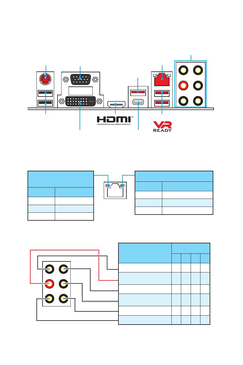
Задняя панель портов ввода/ вывода
USB 3.1 Gen1
Type-C
Подключение/ Работа
индикатора
Состояние Описание
Выкл. Не подключен
Желтый Подключен
Мигает Передача данных
Скорость передачи данных
Состояние Описание
Выкл. 10 Мбит/с подключение
Зеленый 100 Мбит/с подключение
Оранжевый 1 Гбит/с подключение
Таблица состояний индикатора порта LAN
Конфигурация портов Аудио
Задняя панель портов ввода/ вывода
PS/2 LAN
USB 2.0
Порты Аудио
DVI-D
VGA
USB 3.1 Gen1
USB 3.1 Gen1
Порты Аудио
Канал
2 4 6 8
Линейный вход
Линейный выход/ Выход
фронтальных колонок
● ● ● ●
Тыловые колонки ● ● ●
Выход центральной
колонки/ сабвуфера
● ●
Выход боковых колонок ●
Микрофонный вход
(●: подключен, Пусто: не подключен)
8
Задняя панель портов ввода/ вывода
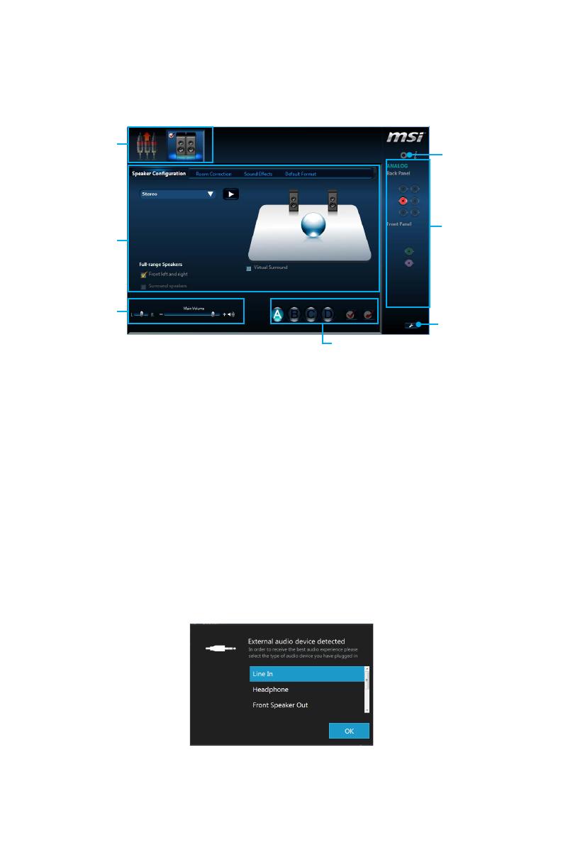
Менеджер Realtek HD Audio
После установки драйвера Realtek HD Audio, в системном трее появится
значок Realtek HD Audio Manager. Дважды щелкните по значку для запуска
приложения.
y Выбор устройства — позволяет выбрать источник аудио выхода и
изменить соответствующие параметры. Отмеченное устройство будет
использоваться по умолчанию.
y Дополнительные эффекты — это список опций по настройке звуковых
эффектов для входного и выходного сигнала аудио устройства.
y Мастер—громкость — регулирует громкость или баланс правой и левой
колонок, подключенных к передней или задней панели.
y Профили — позволяют переключаться между различными профилями.
y Расширенные настройки — обеспечивают работу с двумя независимыми
потоками аудио.
y Состояние разъемов — отображает все устройства воспроизведения и
записи, подключенные к компьютеру.
y Настройки подключений — настраивают параметры подключения.
Автоматическое всплывающее диалоговое окно
При подключении устройства к разъему аудио появится диалоговое окно с
просьбой подтвердить подключенное устройство.
Каждый разъем соответствует его настройкам по умолчанию, как показано
на следующей странице.
Состояние
разъемов
Выбор
устройства
Настройки
подключений
Профили
Мастер—
громкость
Дополнительные
эффекты
Расширенные
настройки
9
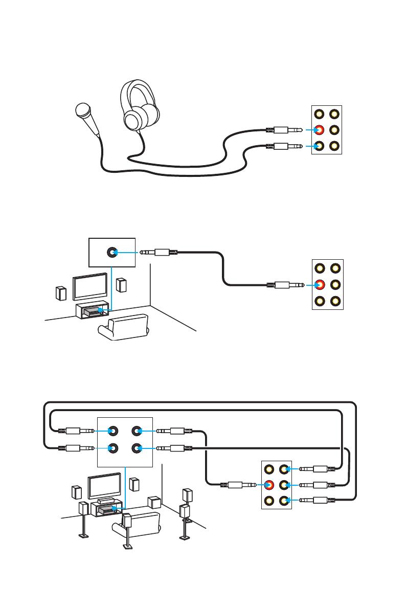
Задняя панель портов ввода/ вывода
Подключение наушников и микрофона
Подключение внешнего стерео усилителя (колонок)
Подключение звуковой системы 7.1
AUDIO INPUT
Rear Front
Side Center/
Subwoofer
AUDIO INPUT
10
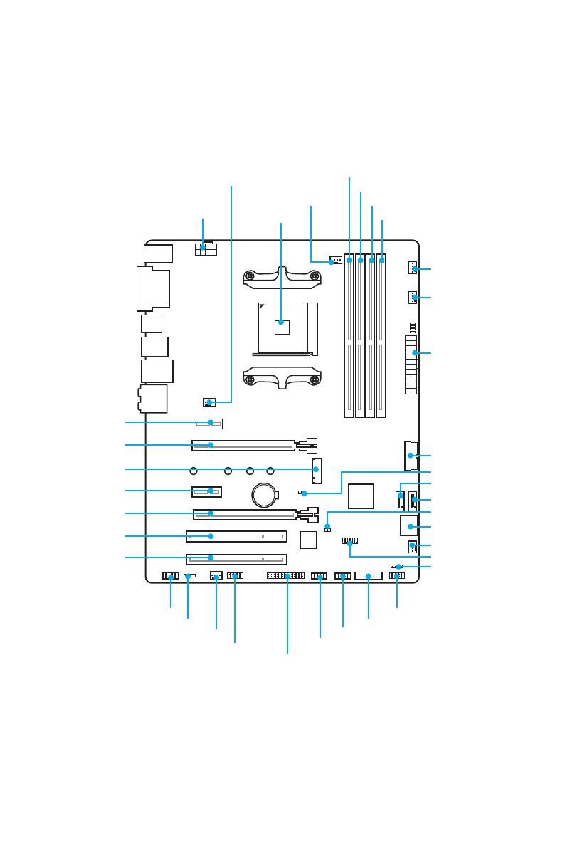
Компоненты материнской платы
BAT1
Компоненты материнской платы
SATA3
SATA4
SATA▼1▲2
CPU_FAN1
PUMP_FAN1
PCI_E1
PCI_E2
PCI_E3
PCI_E4
PCI1
PCI2
Процессорный
сокет
CPU_PWR1
M2_1
DIMMA1
SYS_FAN1
SYS_FAN4
JTPM1
JFP2
JCI1
DIMMA2
DIMMB1
DIMMB2
JFP1
JUSB3
JUSB2
SYS_FAN2
JCOM1
JUSB1
JLPT1
JAUD1
JLED1
ATX_PWR1
SYS_FAN3
JUSB4
JBAT1
11
Компоненты материнской платы
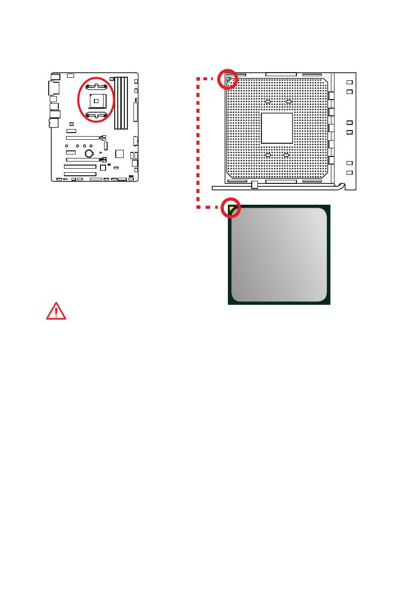
Процессорный сокет
Процессор AM4
На поверхности процессора AM4
имеется золотой треугольник
для правильной установки
процессора относительно
процессорного сокета
материнской платы. Золотой
треугольник указывает на
контакт 1.
Внимание!
y
Из—за особенностей архитектуры процессоров АМ4, замена процессора
может привести к сбросу настроек BIOS до значений по умолчанию.
y
Перед установкой или заменой процессора, необходимо отключить
кабель питания.
y
При установке процессора обязательно установите процессорный
кулер. Кулер, представляющий собой систему охлаждения процессора,
предотвращает перегрев и обеспечивает стабильную работу системы.
y
Перед включением системы проверьте герметичность соединения между
процессором и радиатором.
y
Перегрев может привести к серьезному повреждению процессора и
материнской платы. Всегда проверяйте работоспособность вентилятора
для защиты процессора от перегрева. При установке кулера нанесите
ровный слой термопасты (или термоленту) на крышку установленного
процессора для улучшения теплопередачи.
y
Если вы приобрели отдельно процессор и процессорный кулер,
подробное описание установки см. в документации в данному кулеру.
y
Данная системная плата разработана с учетом возможности ее
«разгона». Перед выполнением разгона системы убедитесь в том,
что все компоненты системы смогут его выдержать. Производитель
не рекомендует использовать параметры, выходящие за пределы
технических характеристик устройств. Гарантия MSI
®
не распространяется
на повреждения и другие возможные последствия ненадлежащей
эксплуатации оборудования.
12
Компоненты материнской платы
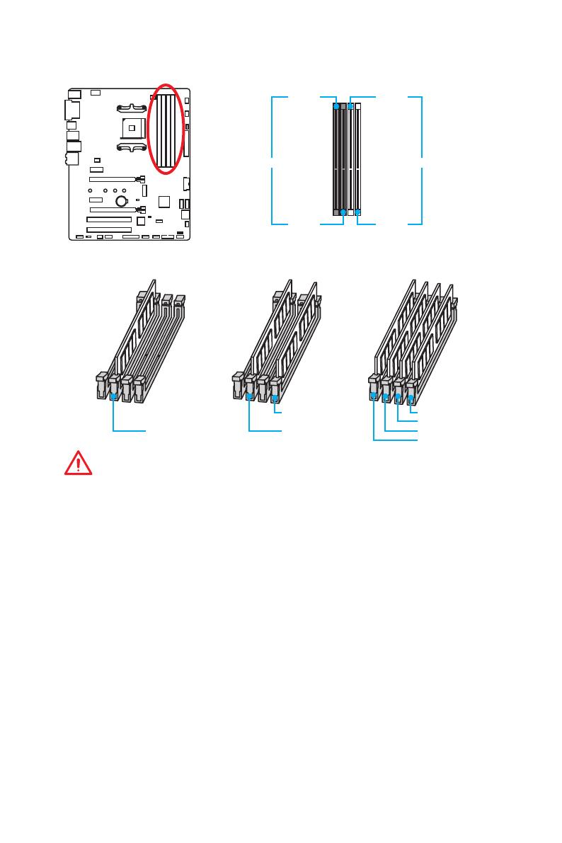
Слоты DIMM
DIMMA1 DIMMB1
Канал A Канал B
DIMMA2 DIMMB2
Рекомендации по установке модулей памяти
DIMMB2 DIMMB2
DIMMB1
DIMMA2 DIMMA2 DIMMA2
DIMMA1
Внимание!
y
Всегда устанавливайте модуль памяти сначала в слот DIMMA2.
y
В связи со спецификой использования ресурсов чипсета, доступный
объем памяти будет немного меньше, чем фактически установленный.
y
На основе характеристик процессора, рекомендуется устанавливать
напряжение на памяти DIMM менее 1.35 В. Это позволит защитить
процессор.
y
Некоторые модули памяти при разгоне могут работать на частотах ниже
заявленной производителем, поскольку выставляемая для памяти частота
зависит от информации, записанной в SPD (Serial Presence Detect). Зайдите
в BIOS и выберите опцию Memory Try It!, чтобы установить заявленную или
более высокую частоту.
y
При установке памяти во все слоты, а также при ее разгоне,
рекомендуется использовать более эффективную систему охлаждения
памяти.
y
Совместимость и стабильность работы установленного модуля памяти
при разгоне зависит от установленного процессора и других устройств.
y
Из—за ограничений официальной спецификации процессора АМ4/
контроллера памяти, модули памяти могут работать на частотах
ниже заявленной производителем при насройках по умолчанию.
Дополнительную информацию о совместимых модулях памяти можно
найти на веб—сайте www.msi.com.
13
Компоненты материнской платы
BAT1
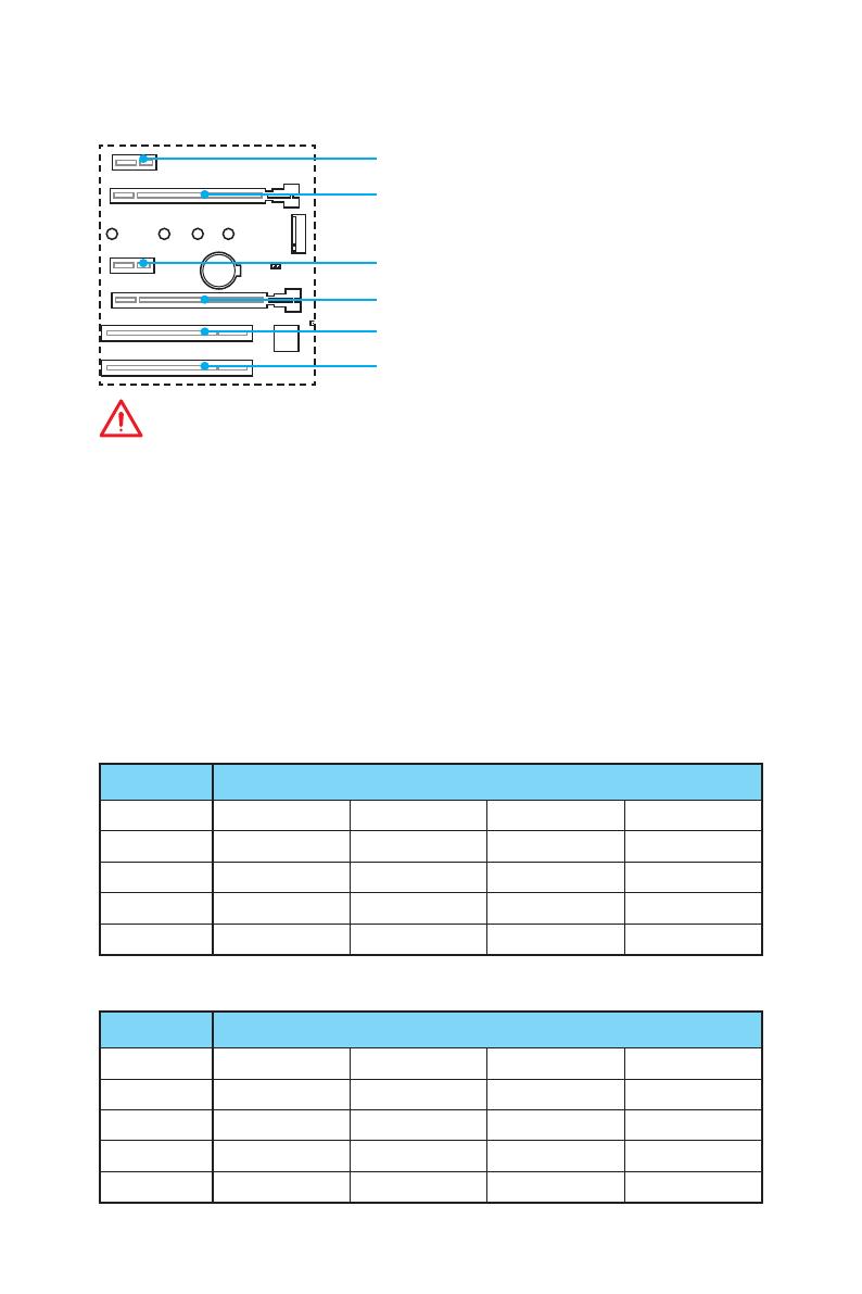
PCI_E1~4, PCI1~2: Слоты расширения PCIe и PCI
PCI_E1: PCIe 2.0 x1
PCI_E2: PCIe 3.0 x16 (процессоры RYZEN серии)
PCIe 3.0 x8 (процессоры A-серии 7-ого
поколения/ Athlon
™
)
PCI_E3: PCIe 2.0 x1
PCI_E4: PCIe 2.0 x4
PCI1: слот PCI
PCI2: слот PCI
Внимание!
y
При установке массивной видеокарты, необходимо использовать такой
инструмент, как MSI Gaming Series Graphics Card Bolster для поддержки
веса графической карты и во избежание деформации слота.
y
Для установки одной карты расширения PCIe x16 с оптимальной
производительностью рекомендуется использовать слот PCI_E2.
y
Перед установкой или извлечением плат расширения убедитесь, что
кабель питания отключен от электрической сети. Прочтите документацию
на карту расширения и выполните необходимые дополнительные
аппаратные или программные изменения для данной карты.
y
Данная материнская плата может поддерживать технологию AMD
®
CrossFire
™
только в том случае, когда оба слота PCIe x1 пусты.
Таблица пропускной способности PCIe
Для процессоров RYZEN серии
Слот Пропускная способность
PCI_E1 Пусто 2.0 x1 Пусто 2.0 x1
PCI_E2 3.0 x16 3.0 x16 3.0 x16 3.0 x16
PCI_E3 Пусто Пусто 2.0 x1 2.0 x1
PCI_E4 2.0 x4 2.0 x2 2.0 x2 2.0 x2
M2_1 3.0 x4 3.0 x4 3.0 x4 3.0 x4
Для процессоров A-серии 7-ого поколения/ Athlon
™
Слот Пропускная способность
PCI_E1 Пусто 2.0 x1 Пусто 2.0 x1
PCI_E2 3.0 x8 3.0 x8 3.0 x8 3.0 x8
PCI_E3 Пусто Пусто 2.0 x1 2.0 x1
PCI_E4 2.0 x4 2.0 x2 2.0 x2 2.0 x2
M2_1 3.0 x2 3.0 x2 3.0 x2 3.0 x2
14
Компоненты материнской платы
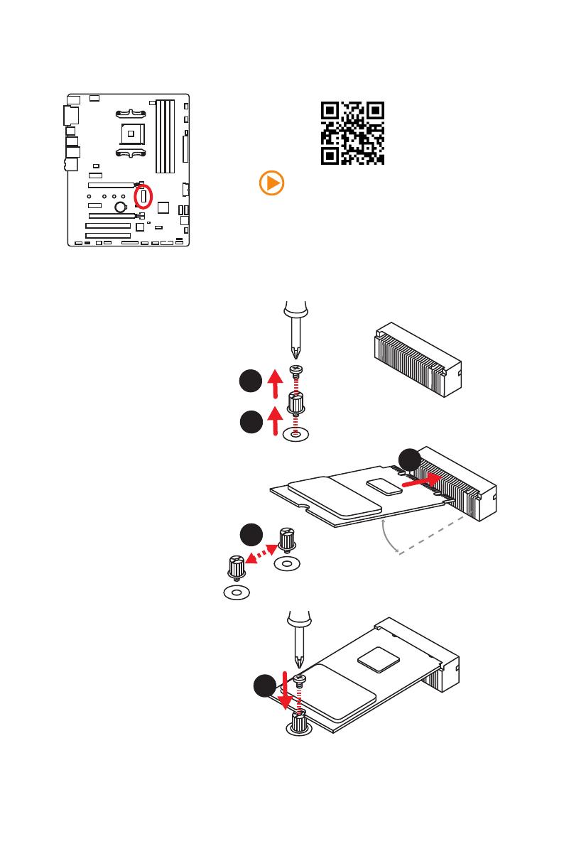
M2_1: Разъем M.2 (Ключ M)
Видео Инструкция
Смотрите видео, чтобы узнать как
установить модуль M.2.
http://youtu.be/JCTFABytrYA
Установка модуля M.2
1
2
3
30°
3. Закрутите стойку
в отверстие,
на расстоянии,
соответствующем
длине вашего модуля
М.2.
4. Вставьте модуль М.2 в
разъем М.2 под углом
30 градусов.
5. Совместите винт с
выемкой на задней
кромке модуля M.2 и
закрутите его в стойку.
1. Выкрутите винт из
стойки.
2. Выкрутите стойку.
4
5
15
Компоненты материнской платы
JAUD1: Разъем аудио передней панели
Данный разъем предназначен для подключения аудиоразъемов передней
панели.
1
2 10
9
1 MIC L 2 Ground
3 MIC R 4 NC
5 Head Phone R 6 MIC Detection
7 SENSE_SEND 8 No Pin
9 Head Phone L 10 Head Phone Detection
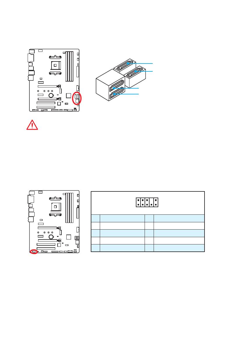
SATA1~4: Разъемы SATA 6 Гб/с
Эти разъемы представляют собой интерфейсные порты SATA 6 Гб/с. К
каждому порту можно подключить одно устройство SATA.
SATA4
SATA1
SATA2
SATA3
Внимание!
y
Избегайте перегибов кабеля SATA под прямым углом. В противном случае,
возможна потеря данных при передаче.
y
Кабели SATA оснащены одинаковыми коннекторами с обеих сторон.
Однако, для экономии занимаемого пространства к материнской плате
рекомендуется подключать плоский разъем.
16
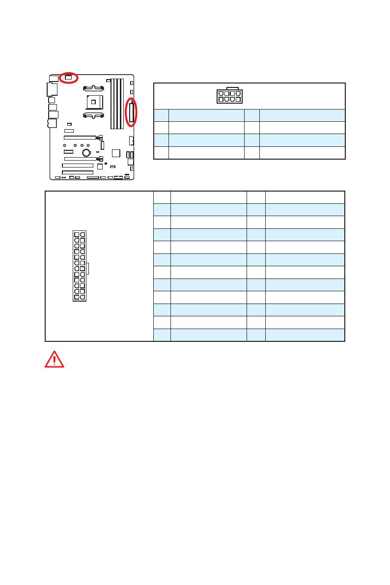
Компоненты материнской платы
24
131
12
ATX_PWR1
1 +3.3V 13 +3.3V
2 +3.3V 14 -12V
3 Ground 15 Ground
4 +5V 16 PS-ON#
5 Ground 17 Ground
6 +5V 18 Ground
7 Ground 19 Ground
8 PWR OK 20 Res
9 5VSB 21 +5V
10 +12V 22 +5V
11 +12V 23 +5V
12 +3.3V 24 Ground
5
4 1
8
CPU_PWR1
1 Ground 5 +12V
2 Ground 6 +12V
3 Ground 7 +12V
4 Ground 8 +12V
CPU_PWR1, ATX_PWR1: Разъемы питания
Данные разъемы предназначены для подключения блока питания ATX.
Внимание!
Для обеспечения стабильной работы системной платы проверьте
надежность подключения всех кабелей питания к блоку питания АТХ.
17
Компоненты материнской платы
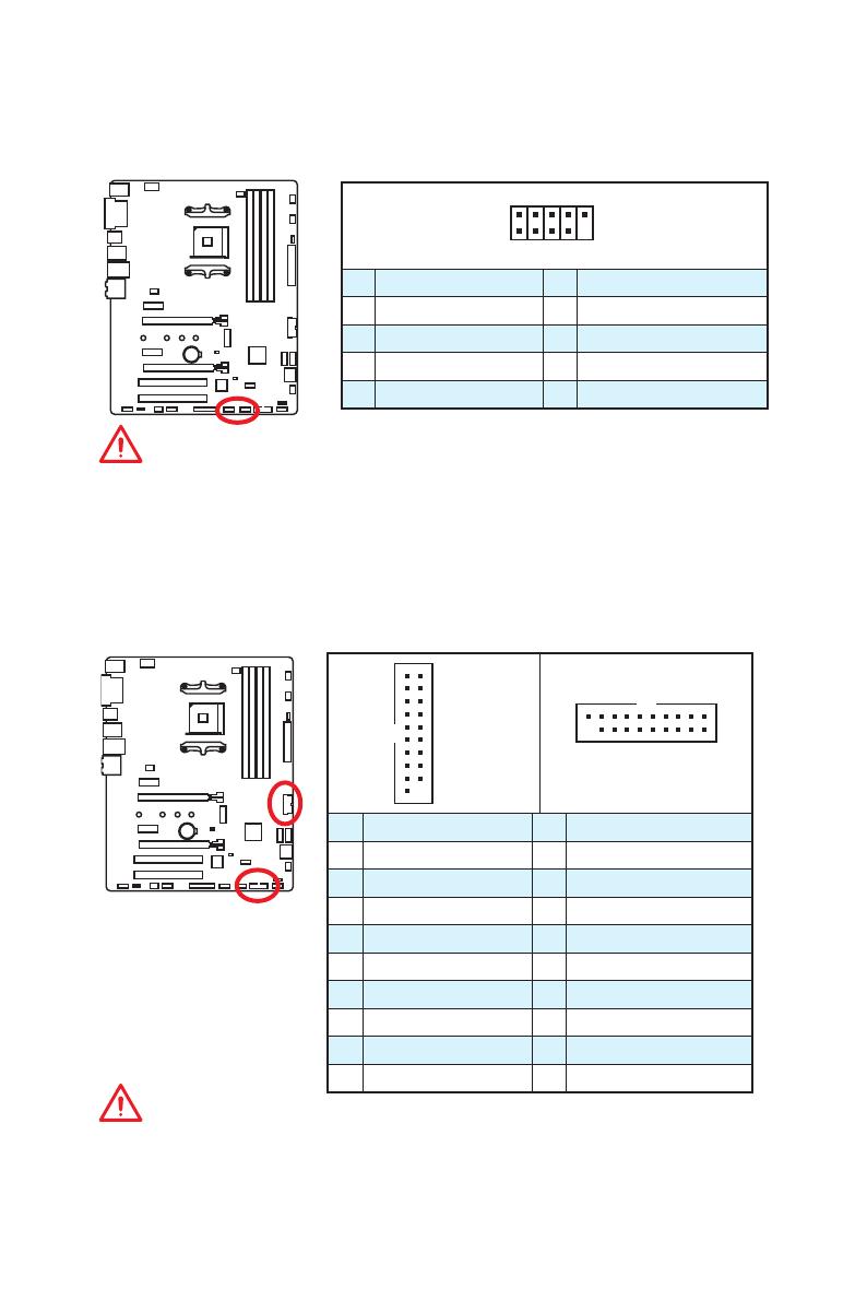
JUSB1~2: Разъемы USB 2.0
Данные разъемы предназначены для подключения портов USB 2.0 на
передней панели.
1
2 10
9
1 VCC 2 VCC
3 USB0- 4 USB1-
5 USB0+ 6 USB1+
7 Ground 8 Ground
9 No Pin 10 NC
Внимание!
y
Помните, что во избежание повреждений, необходимо правильно
подключать контакты VCC и земли.
y
Для того, чтобы зарядить ваш iPad, iPhone и iPod через порты USB,
пожалуйста, установите утилиту MSI
®
SUPER CHARGER.
JUSB3~4: Разъемы USB 3.1 Gen1
Данные разъемы предназначены для подключения портов USB 3.1 Gen1 на
передней панели.
1
10 11
20
JUSB4
JUSB3
1
10
11
20
1 Power 11 USB2.0+
2 USB3_RX_DN 12 USB2.0-
3 USB3_RX_DP 13 Ground
4 Ground 14 USB3_TX_C_DP
5 USB3_TX_C_DN 15 USB3_TX_C_DN
6 USB3_TX_C_DP 16 Ground
7 Ground 17 USB3_RX_DP
8 USB2.0- 18 USB3_RX_DN
9 USB2.0+ 19 Power
10 NC 20 No Pin
Внимание!
Помните, что во избежание повреждений, необходимо правильно
подключать контакты VCC и земли.
18
Компоненты материнской платы
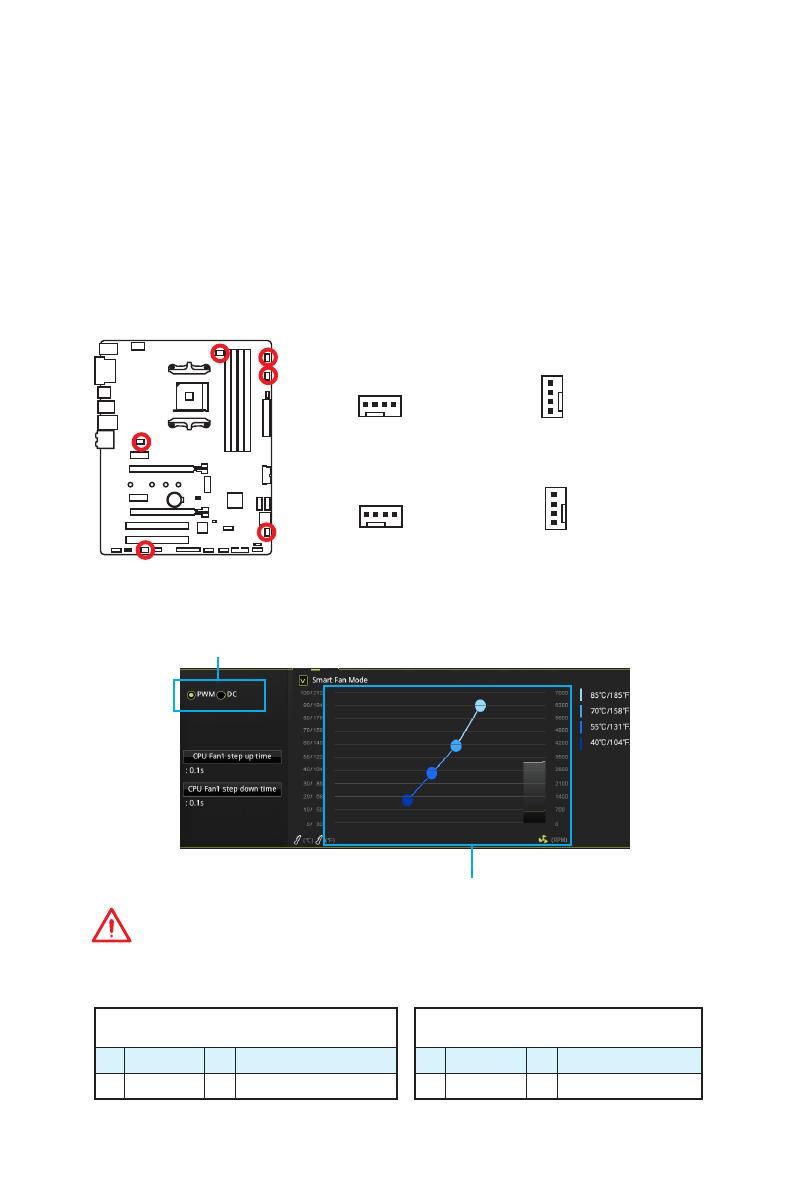
CPU_FAN1, PUMP_FAN1, SYS_FAN1~4: Разъемы вентиляторов
Разъемы вентиляторов можно разделить на два типа: с PWM (PulseWidth
Modulation) управлением и управлением постоянным током. Разъемы
вентиляторов с PWM управлением имеют контакт с постоянным
напряжением 12В, а также контакт с сигналом управления скоростью
вращения. Управление скоростью вращения вентиляторов с управлением
постоянным током, осуществляется через соответсвующие разъемы
путем изменения величины напряжения. Поэтому, при подключении
3-х контактного (Non-PWM) вентилятора к разъему для вентилятора
PWM, скорость вентилятора всегда будет максимальной. Работа такого
вентилятора может оказаться достаточно шумной. Для настройки режима
работы вентилятора, PWM или DC, следуйте указаниям ниже.
Назначение контактов разъема для режима
PWM
1 Ground 2 +12V
3 Sense 4 Speed Control Signal
Назначение контактов разъема для
режима DC
1 Ground 2 Voltage Control
3 Sense 4 NC
Разъем вентилятора с PWM управлением
по умолчанию
Разъем вентилятора с управлением
постоянным током по умолчанию
Переключение режимов работы и скорости вращения вентилятора
В меню BIOS > HARDWARE MONITOR вы можете выбрать режив работы
вентилятора: PWM или DC, а также настроить его скорость вращения.
Выберите режим PWM или DC
Внимание!
Убедитесь, что вентиляторы работают правильно после выбора режима PWM/ DC.
Вы можете регулировать скорость вращения вентилятора
в зависимости от температуры процессора путем
изменения положения градиентных точек.
1
CPU_FAN1
1
SYS_FAN3/ SYS_FAN4
1
SYS_FAN1/ SYS_FAN2
Назначение контактов разъема для подключения вентилятора
1
PUMP_FAN1
19
Компоненты материнской платы
JCI1: Разъем датчика открытия корпуса
К этому разъему подключается кабель от датчика открытия корпуса.
Нормально
(По умолчанию)
Разрешить запись
по событию
открытия корпуса
Использование датчика открытия корпуса
1. Подключите датчик открытия корпуса к разъему JCI1.
2. Закройте крышку корпуса.
3. Войдите в BIOS > SETTINGS > Security > Chassis Intrusion Configuration.
4. Установите Chassis Intrusion в Enabled.
5. Нажмите клавишу F10, чтобы сохранить настройки и выйти, а затем
нажмите клавишу Enter, чтобы выбрать Yes.
6. При открытии корпуса на экране будет появляться предупреждающее
сообщение каждый раз при включении компьютера.
Сброс сообщения об открытии корпуса
1. Войдите в BIOS > SETTINGS > Security > Chassis Intrusion Configuration.
2. Выберите Chassis Intrusion, Reset.
3. Нажмите клавишу F10, чтобы сохранить настройки и выйти, а затем
нажмите клавишу Enter, чтобы выбрать Yes.
1
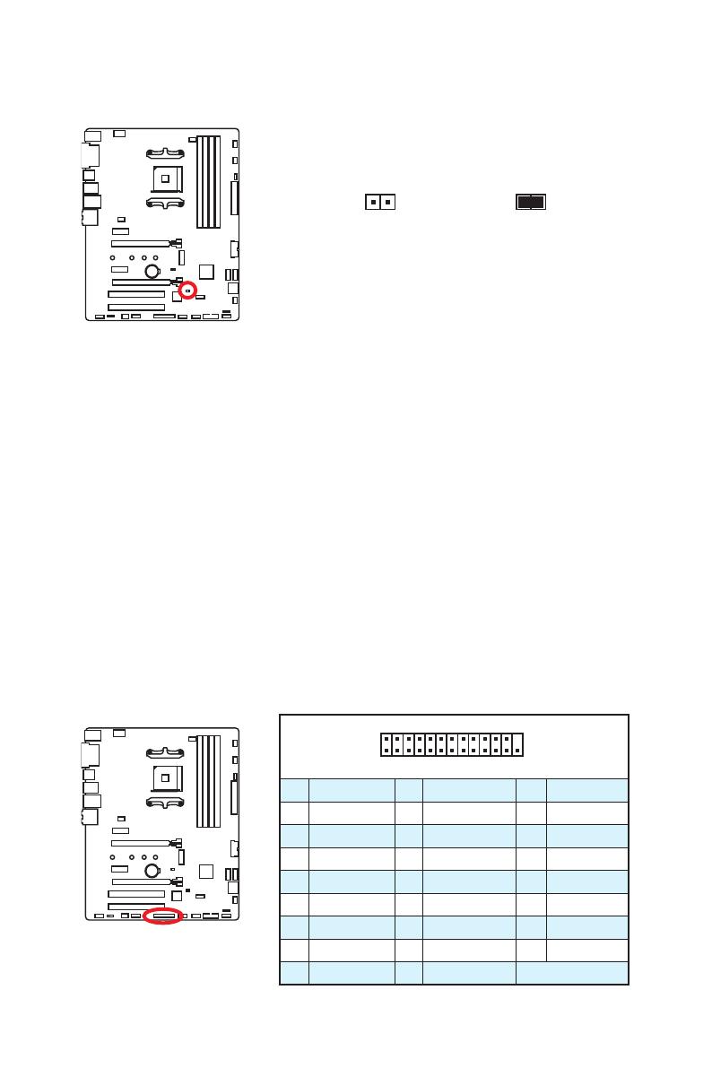
2 26
25
1 RSTB# 2 AFD# 3 PRND0
4 ERR# 5 PRND1 6 PINIT#
7 PRND2 8 LPT_SLIN# 9 PRND3
10 Ground 11 PRND4 12 Ground
13 PRND5 14 Ground 15 PRND6
16 Ground 17 PRND7 18 Ground
19 ACK# 20 Ground 21 BUSY
22 Ground 23 PE 24 Ground
25 SLCT 26 No Pin
JLPT1: Разъем паралельного порта
Данный разъем позволяет подключить паралельный порт, размещенный на
внешнем бракете.
/
на других языках
Похожие инструкции
Другие инструкции
MSI B350 TOMAHAWK: List of Available Documents
Note for Owners:
Guidesimo.com webproject is not a service center of MSI trademark and does not carries out works for diagnosis and repair of faulty MSI B350 TOMAHAWK equipment. For quality services, please contact an official service center of MSI company. On our website you can read and download documentation for your MSI B350 TOMAHAWK device for free and familiarize yourself with the technical specifications of device.
More Motherboard Devices:
-
Terasic THDB-HTG
Terasic THDB-HTG THDB-HTG Terasic HSTC to GPIO Daughter Board User Manual Document Version 1.0 DEC. 23, 2008 by Terasic …
THDB-HTG Motherboard, 20
-
Cypress Semiconductor MB2146-302A
Cypress Semiconductor198 Champion CourtSan Jose, CA 95134-1709Phone (USA): 800.858.1810Phone (Intnl): +1.408.943.2600www.cypress.comF2MC-8FX FamilyMCU Board for MB95FV100D-102MB2146-302A, Operation ManualDoc. # 002-07488 Rev. *B …
MB2146-302A Motherboard, 29
-
Rohm BD7682FJ-LB-EVK-302
1/4 QUICK START GUIDE © 2020 ROHM Co., Ltd. No. 63QS003E Rev.001 SEPT.2020 100 W Auxiliary Power Supply Eval Board BD7682FJ-LB-EVK-302 This quick start guide will help you understand the connection, operating Instructions and important notices and warnings that need to be carefully reviewed prior to use of the board (Figure 1). For further information please refer to the user guide (No. 63UG06 …
BD7682FJ-LB-EVK-302 Motherboard, 5
-
IEI Technology SPCIE-C236
1 Full-size PICMG 1.3 CPU Card supports LGA1151 Intel E3-1200/Core™ i3/Pentium®/Celeron® CPU per Intel® C236, DDR4, VGA/IDP, Dual Intel® PCIe GbE, USB 3.0, SATA 6Gb/s, HD Audio, iAMT, and RoHS SPCIE-C236 Quick Installation Guide Version 1.0 Jul 27, 2016. Package List SPCIE-C236 package includes the following items: 1 x SPCIE-C236 single board computer 1 x SATA cable (P …
SPCIE-C236 Motherboard, 17
-
Texas Instruments TPD2E1B06DRLEVM
User’s GuideSLVU917–August 2013TPD2E1B06DRLEVMThis user’s guide describes the characteristics, operation, and use of the TPD2E1B06DRLEVM evaluationmodule (EVM). This EVM includes 7 TPD2E1B06DRL’s in various configurations for testing. FiveTPD2E1B06DRL’s are configured for IEC61000-4-2 compliance testing, one TPD2E1B06DRL isconfigured for 4-port s-parameter analysis, and one is conf …
TPD2E1B06DRLEVM Motherboard, 12
Recommended Documentation:
Инструкцию для MSI B350 TOMAHAWK на русском языке, в формате pdf можно скачать с нашего сайта. Наш каталог предоставляем Вам инструкцию производителя фирмы MSI, которая была взята из открытых источников. Ознакомившись с руководством по эксплуатации от MSI, Вы на все 100% и правильно сможете воспользоваться всеми функциями устройства.
Для сохранения инструкции «Материнская плата MSI B350 TOMAHAWK» на русском языке на вашем компьютере либо телефоне, нажмите кнопку «Скачать инструкцию». Если активна кнопка «Инструкция онлайн», то Вы можете просмотреть документ (manual), в своём браузере онлайн.
Если у Вас нет возможности скачать инструкцию по эксплуатации либо просмотреть её, Вы можете поделиться ссылкой на эту страницу в социальных сетях и при удобном моменте скачать инструкцию. Либо добавьте эту страницу в закладки Вашего браузера, нажав кнопку «Добавить страницу в закладки браузера».