Посмотреть инструкция для MSI B550-A Pro бесплатно. Руководство относится к категории материнские платы, 10 человек(а) дали ему среднюю оценку 8.7. Руководство доступно на следующих языках: английский. У вас есть вопрос о MSI B550-A Pro или вам нужна помощь? Задайте свой вопрос здесь
Не можете найти ответ на свой вопрос в руководстве? Вы можете найти ответ на свой вопрос ниже, в разделе часто задаваемых вопросов о MSI B550-A Pro.
Какой вес MSI B550-A Pro?
Какая высота MSI B550-A Pro?
Какая ширина MSI B550-A Pro?
Какая толщина MSI B550-A Pro?
Инструкция MSI B550-A Pro доступно в русский?
Не нашли свой вопрос? Задайте свой вопрос здесь
-
Contents
-
Table of Contents
-
Bookmarks
Quick Links
Quick Start
Thank you for purchasing the MSI®
Quick Start section provides demonstration diagrams about how to
install your computer. Some of the installations also provide video
demonstrations. Please link to the URL to watch it with the web
browser on your phone or tablet. You may have even link to the URL
by scanning the QR code.
クイ ックスタート
この度は MSI®
B550-A PRO
ありがとうございます 。 このクイックスタートにはPCの組み立て方法の
デモンス トレーション図を掲載しています。 いく つかの組み立て手順に付
きましては、 実演ビデオを提供しています。 スマートフ ォンやタブレッ ト端
末のウェブブラウザで本書に記載されたURLにアクセスしてご覧くださ
い。 QRコードをスキャンすることでもURLのリンク先をご参照頂けます。
퀵 스타트
MSI®
B550-A PRO
컴퓨터를 설치하는 방법에 대한 데모 다이어그램과 일부 데모 동영상을
제공하고 있습니다. 휴대전화 또는 태블릿의 웹 브라우저를 통하여 URL에
링크한 후 설치 동영상을 감상하시기 바랍니다. 또는 QR 코드를 스캔하여
URL에 링크할 수도 있습니다.
快速指引
感謝您購買 MSI®
腦的示範圖解 , 亦提供部分組件的安裝示範影片 ; 請您以智慧型手機或
平板的瀏覽器連上 URL 網址進行觀看。 您也可以掃描 QR code 的方式
快速連接至網址 。
快速入门
感谢您购买 MSI®
安装计算机演示图。 某些设施还提供了视频演示。 请使用您的手机或平
板电脑上的网页浏览器链接至网址观看。 您也可以通过扫描QR码链接
到URL。
マザーボードをお買い上げいただき、 誠に
메인보드를 선택해주셔서 감사합니다. 이 부분에서는
B550-A PRO
主機板 。 本快速指引章節提供您安裝電
B550-A PRO
主板。 本快速入门部分提供了有关如何
B550-A PRO
motherboard. This
I
Quick Start
Chapters
Summary of Contents for MSI B550-A PRO
Материнская плата msi B550M-A Pro

Спасибо за покупку MSI® Б550М-А ПРО/ А520М-А ПРО материнская плата. В этом руководстве пользователя содержится информация о компоновке платы, компонентахview, Настройка BIOS и установка программного обеспечения.
Информация по технике безопасности
- Компоненты, входящие в этот комплект, подвержены повреждению электростатическим разрядом (ESD). Пожалуйста, придерживайтесь следующих инструкций, чтобы обеспечить успешную сборку компьютера.
- Убедитесь, что все компоненты надежно подключены. Плохое соединение может привести к тому, что компьютер не распознает компонент или не запустится.
- Держите материнскую плату за края, чтобы не прикасаться к чувствительным компонентам.
- При обращении с материнской платой рекомендуется носить браслет с защитой от электростатического разряда (ESD), чтобы предотвратить электростатическое повреждение. Если браслет для защиты от электростатического разряда недоступен, снимите с себя статическое электричество, прикоснувшись к другому металлическому предмету, прежде чем брать в руки материнскую плату.
- Храните материнскую плату в контейнере для защиты от статического электричества или на антистатической прокладке, если материнская плата не установлена.
- Перед включением компьютера убедитесь, что на материнской плате или где-либо в корпусе компьютера нет незакрепленных винтов или металлических компонентов.
- Не загружайте компьютер до завершения установки. Это может привести к необратимому повреждению компонентов, а также к травмам пользователя.
- Если вам потребуется помощь на любом этапе установки, обратитесь к сертифицированному специалисту по компьютерам.
- Всегда выключайте источник питания и отсоединяйте шнур питания от розетки перед установкой или извлечением каких-либо компонентов компьютера.
- Сохраните это руководство для использования в будущем.
- Берегите материнскую плату от влаги.
- Убедитесь, что ваша электрическая розетка обеспечивает такую же мощность.tage, как указано на блоке питания, перед подключением блока питания к электрической розетке.
- Разместите шнур питания таким образом, чтобы на него нельзя было наступить. Не кладите ничего на шнур питания.
- Следует отметить все предостережения и предупреждения на материнской плате.
- При возникновении любой из следующих ситуаций обратитесь к обслуживающему персоналу для проверки материнской платы:
▪ В компьютер попала жидкость.
▪ Материнская плата подверглась воздействию влаги.
▪ Материнская плата работает неправильно или вы не можете заставить ее работать в соответствии с руководством пользователя.
▪ Материнская плата упала и была повреждена.
▪ Материнская плата имеет явные признаки поломки. - Не оставляйте материнскую плату при температуре выше 60 ° C (140 ° F), это может повредить материнскую плату.
Характеристики
| ЦП | Поддержка процессоров AMD Ryzen™ 3-го поколения для настольных ПК и процессоров AMD Ryzen™4000 серии G для настольных ПК |
| Набор микросхем |
|
| Память |
* Пожалуйста, обратитесь www.msi.com для получения дополнительной информации о совместимой памяти. |
| Слоты расширения |
* Спецификации PCIe могут различаться в зависимости от установленного процессора. |
| Onboard Графика |
* Доступно для процессора со встроенной графикой. |
| Аудио | Кодек Realtek® ALC892
▪ 7.1-канальный звук высокой четкости |
| ЛВС |
|
| Хранилище | Чипсет AMD B550/A520
* Спецификации PCIe могут различаться в зависимости от установленного процессора. |
| USB | Чипсет AMD B550/A520
▪ Два порта USB 2 Gen 3.2 1 Гбит/с доступны через внутренний разъем USB 5 Gen 3.2 1 Гбит/с. Процессор AMD ▪ 4 порта USB 3.2 Gen 1 5 Гбит/с Type-A на задней панели |
| Внутренние разъемы |
|
| Разъемы задней панели |
|
| Контроллер ввода / вывода | Микросхема контроллера NUVOTON NCT6687-R |
|
Монитор оборудования |
|
| Форм-фактор |
|
| Возможности BIOS |
|
| Software |
|
| Особенности Dragon Center |
|
 Пожалуйста, обратитесь к http://download.msi.com/manual/mb/DRAGONCENTER2.pdf Больше подробностей.
Задняя панель ввода-вывода

Таблица состояния индикатора порта LAN

Аудио 7.1-канальная конфигурация
Для настройки 7.1-канального звука необходимо подключить передний аудиомодуль ввода / вывода к разъему JAUD1 и выполнить следующие шаги.
- Нажмите на Realtek HD Audio Manager> Расширенные настройки чтобы открыть диалоговое окно ниже.

- Выберите «Отключить звук на заднем устройстве вывода», когда к нему подключены передние наушники.
- Подключите динамики к аудиоразъемам на задней и передней панели ввода / вывода. Когда вы подключаете устройство к аудиоразъему, появляется диалоговое окно с вопросом, какое устройство подключено в данный момент.

Болееview компонентов

* Расстояние от центра ЦП до ближайшего слота DIMM.
Процессорное гнездо
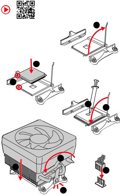
Пожалуйста, установите ЦП в гнездо ЦП, как показано ниже.

![]() Важнo
Важнo
- Всегда отключайте шнур питания от розетки перед установкой или снятием ЦП.
- Сохраните защитный колпачок процессора после установки процессора. MSI будет обрабатывать запросы на возврат товара (RMA), если только на материнской плате есть защитная крышка на разъеме ЦП.
- При установке ЦП всегда не забывайте устанавливать радиатор ЦП. Радиатор процессора необходим для предотвращения перегрева и поддержания стабильности системы.
- Перед загрузкой системы убедитесь, что радиатор ЦП плотно прилегает к ЦП.
- Перегрев может серьезно повредить процессор и материнскую плату. Всегда проверяйте, правильно ли работают охлаждающие вентиляторы, чтобы защитить ЦП от перегрева. Обязательно нанесите ровный слой термопасты (или термоленты) между процессором и радиатором, чтобы улучшить отвод тепла.
- Если вы приобрели отдельный ЦП и радиатор / кулер, пожалуйста, обратитесь к документации в комплекте радиатора / кулера для получения более подробной информации об установке.
Слоты DIMM
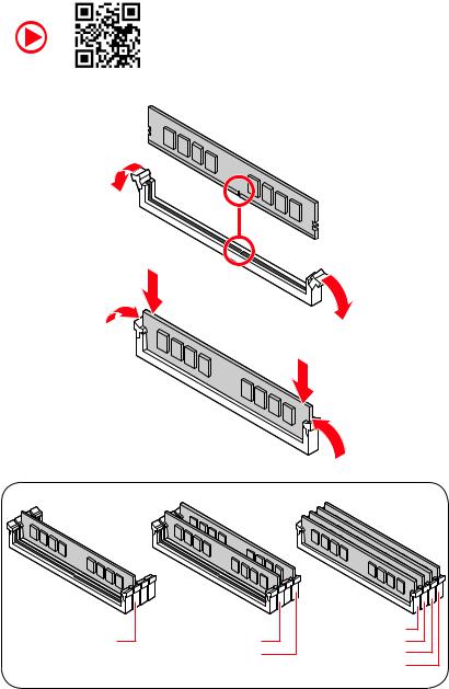
Установите модуль памяти в слот DIMM, как показано ниже.
![]() Важнo
Важнo
- Из-за использования ресурсов чипсета доступный объем памяти будет немного меньше установленного.
- Обратите внимание, что максимальный объем адресуемой памяти составляет 4 ГБ или менее для 32-разрядной ОС Windows из-за ограничения адреса памяти. Поэтому мы рекомендуем вам установить 64-битную ОС Windows, если вы хотите установить на материнскую плату более 4 ГБ памяти.
PCI_E1 ~ 2: Слоты расширения PCIe

![]() Важнo
Важнo
- Если вы устанавливаете большую и тяжелую видеокарту, вам понадобится такой инструмент, как Подставка для видеокарт MSI Gaming Series чтобы выдержать его вес, чтобы предотвратить деформацию паза.
- При добавлении или удалении карт расширения всегда выключайте источник питания и отсоединяйте кабель питания от розетки. Прочтите документацию карты расширения, чтобы проверить наличие необходимых дополнительных изменений оборудования или программного обеспечения.
M2_1: слот M.2
Установите устройство M.2 в слот M.2, как показано ниже.

SATA1 ~ 4: Разъемы SATA 6 Гбит / с
Эти разъемы представляют собой интерфейсные порты SATA 6 Гбит / с. Каждый разъем может подключаться к одному устройству SATA.

![]() Важнo
Важнo
- Не складывайте кабель SATA под углом 90 градусов. В противном случае во время передачи может произойти потеря данных.
- Кабели SATA имеют одинаковые разъемы с обеих сторон кабеля. Однако рекомендуется подключать плоский разъем к материнской плате в целях экономии места.
JFP1, JFP2: разъемы передней панели
Эти разъемы подключаются к переключателям и светодиодам на передней панели.

JAUD1: Передний аудиоразъем
Этот разъем позволяет подключать аудиоразъемы на передней панели.

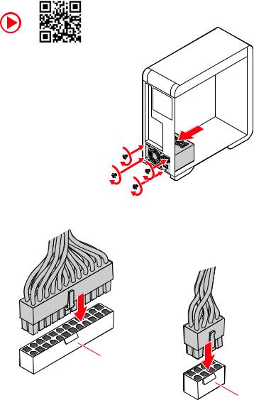
ATX_PWR1, CPU_PWR1: разъемы питания
Эти разъемы позволяют подключать блок питания ATX.

![]() Важнo
Важнo
Убедитесь, что все кабели питания надежно подключены к соответствующему блоку питания ATX, чтобы обеспечить стабильную работу материнской платы.
JUSB1, JUSB2: разъемы USB 2.0
Эти разъемы позволяют подключать порты USB 2.0 на передней панели.

![]() Важнo
Важнo
- Обратите внимание, что контакты VCC и заземления должны быть подключены правильно, чтобы избежать возможных повреждений.
- Чтобы зарядить iPad, iPhone и iPod через порты USB, установите программное обеспечение MSI® SUPER CHARGER.
JUSB3: Разъем USB 3.2 Gen1
Эти разъемы позволяют подключать порты USB 3.2 Gen1 на передней панели.

![]() Важнo
Важнo
Обратите внимание, что контакты питания и заземления должны быть подключены правильно, чтобы избежать возможных повреждений.
CPU_FAN1, SYS_FAN1: разъемы вентилятора
Разъемы вентилятора в режиме ШИМ обеспечивают постоянное выходное напряжение 12 В и регулируют скорость вентилятора с помощью сигнала управления скоростью. Когда вы подключаете 3-контактный вентилятор (без ШИМ) к разъему вентилятора в режиме ШИМ, скорость вентилятора всегда будет поддерживаться на уровне 100%, что может создавать много шума.

![]() Важнo
Важнo
Вы можете регулировать скорость вентилятора в BIOS> Монитор оборудования
JTPM1: Разъем модуля TPM
Этот разъем предназначен для TPM (доверенного платформенного модуля). Дополнительные сведения и способы использования см. В руководстве по платформе безопасности TPM.

JCI1: Разъем обнаружения вторжения в корпус
Этот разъем позволяет подключать кабель переключателя вскрытия корпуса.
Использование детектора вскрытия корпуса
- Подключить JCI1 разъем к переключателю / датчику вскрытия корпуса на корпусе.
- Закройте крышку корпуса.
- Перейдите на BIOS> НАСТРОЙКИ> Безопасность> Конфигурация вскрытия корпуса.
- Поставьте Несанкционированное проникновение в корпус в Enabled.
- Нажмите F10 для сохранения и выхода, а затем нажмите Enter ключ для выбора Да.
- После того, как крышка корпуса снова откроется, при включении компьютера на экране отобразится предупреждающее сообщение.
Сброс предупреждения о вторжении в корпус
- Перейдите на BIOS> НАСТРОЙКИ> Безопасность> Конфигурация вскрытия корпуса.
- Установите для параметра Chassis Intrusion значение Reset.
- Нажмите F10, чтобы сохранить и выйти, а затем нажмите клавишу Enter, чтобы выбрать Да.
JCOM1: Разъем последовательного порта
Этот разъем позволяет подключать дополнительный последовательный порт с помощью планки.
JBAT1: перемычка очистки CMOS (сброса BIOS)
На плате имеется память CMOS, которая питается от батареи, расположенной на материнской плате, для сохранения данных конфигурации системы. Если вы хотите очистить конфигурацию системы, установите перемычки для очистки памяти CMOS.
Сброс BIOS до значений по умолчанию
- Выключите компьютер и отсоедините шнур питания.
- Используйте перемычку, чтобы замкнуть JBAT1 примерно на 5-10 секунд.
- Снимите перемычку с JBAT1.
- Подключите шнур питания и включите компьютер.
Индикатор отладки EZ
Эти светодиоды показывают состояние материнской платы.
![]() ЦП — указывает на то, что ЦП не обнаружен или неисправен.
ЦП — указывает на то, что ЦП не обнаружен или неисправен.![]() Динамическое ОЗУ — указывает, что DRAM не обнаружен или неисправен.
Динамическое ОЗУ — указывает, что DRAM не обнаружен или неисправен.![]() VGA — указывает на то, что графический процессор не обнаружен или неисправен.
VGA — указывает на то, что графический процессор не обнаружен или неисправен.![]() BOAT — указывает, что загрузочное устройство не обнаружено или не работает.
BOAT — указывает, что загрузочное устройство не обнаружено или не работает.
UEFI BIOS
MSI UEFI BIOS совместим с архитектурой UEFI (Unified Extensible Firmware Interface). UEFI имеет много новых функций и расширенных возможностей.tagЭтого не может достичь традиционный BIOS, и в будущем он полностью заменит BIOS. BIOS MSI UEFI использует UEFI в качестве режима загрузки по умолчанию, чтобы полностью продвинуться вперед.tage возможностей нового чипсета. Тем не менее, он по-прежнему имеет режим CSM (модуль поддержки совместимости), чтобы быть совместимым со старыми устройствами. Это позволяет заменять устаревшие устройства на устройства, совместимые с UEFI, во время перехода.
![]() Важнo
Важнo
Термин BIOS в этом руководстве пользователя относится к UEFI BIOS, если не указано иное.
UEFI Advantages
- Быстрая загрузка — UEFI может напрямую загружать операционную систему и сохранять процесс самотестирования BIOS. А также исключает время переключения в режим CSM во время POST.
- Поддерживает разделы жесткого диска размером более 2 ТБ.
- Поддерживает более 4 основных разделов с таблицей разделов GUID (GPT).
- Поддерживает неограниченное количество разделов.
- Поддерживает все возможности новых устройств — новые устройства могут не обеспечивать обратную совместимость.
- Поддерживает безопасный запуск — UEFI может проверить действительность операционной системы, чтобы убедиться в отсутствии вредоносных программ.ampers с процессом запуска.
Несовместимые случаи UEFI
- 32-битная операционная система Windows — Эта материнская плата поддерживает только 64-битную операционную систему Windows 10.
- Старая видеокарта — система обнаружит вашу видеокарту. При отображении предупреждающего сообщения В этой видеокарте не обнаружена поддержка GOP (протокол вывода графики).
![]() Важнo
Важнo
Мы рекомендуем вам использовать видеокарту, совместимую с GOP / UEFI.
Как проверить режим BIOS?
После входа в BIOS найдите режим BIOS в верхней части экрана.

Настройка биоса
Настройки по умолчанию обеспечивают оптимальную производительность для стабильности системы в нормальных условиях. Вам следует всегда сохраняйте настройки по умолчанию чтобы избежать возможного повреждения системы или сбоя при загрузке, если вы не знакомы с BIOS.
![]() Важнo
Важнo
- Элементы BIOS постоянно обновляются для повышения производительности системы. Поэтому описание может немного отличаться от последней версии BIOS, и его следует использовать только для справки. Вы также можете обратиться к ПОМОГИТЕ информационная панель для описания пункта BIOS.
- Элементы BIOS зависят от процессора.
Вход в программу настройки BIOS
Нажмите Удалить ключ, когда Нажмите клавишу DEL, чтобы войти в меню настройки, F11, чтобы войти в меню загрузки. сообщение появляется на экране во время процесса загрузки.
Функциональная клавиша
F1: Общая помощь
F2: Добавить / удалить любимый элемент
F3: Войдите в меню избранного
F4: Войдите в меню характеристик процессора
F5: Войдите в меню Memory-Z
F6: Загрузите оптимальные настройки по умолчанию
F7: Переключение между расширенным режимом и режимом EZ
F8: Загрузить Overclocking Profile
F9: Сохранить Overclocking Profile
F10: Сохранить изменения и сбросить *
F12: Сделайте снимок экрана и сохраните его на USB-накопитель (только в формате FAT / FAT32).
Ctrl + F: Войти на страницу поиска
* Когда вы нажимаете F10, появляется окно подтверждения с информацией об изменении. Выберите «Да» или «Нет», чтобы подтвердить свой выбор.
Сброс BIOS
Для решения определенных проблем может потребоваться восстановить настройки BIOS по умолчанию. Сбросить BIOS можно несколькими способами:
- Зайдите в BIOS и нажмите F6 для загрузки оптимизированных значений по умолчанию.
- Коротко Очистить CMOS перемычка на материнской плате.
![]() Важнo
Важнo
Пожалуйста, обратитесь к Очистить CMOS секция перемычек для сброса BIOS.
Обновление BIOS
Обновление BIOS с помощью M-FLASH
Перед обновлением:
Загрузите последнюю версию BIOS file соответствует модели вашей материнской платы от MSI webсайт. А затем сохраните BIOS file на USB-накопитель.
Обновление BIOS:
- Вставьте USB-накопитель с обновлением. file в порт USB.
- Воспользуйтесь следующими способами, чтобы войти в режим вспышки.
▪ Перезагрузитесь и нажмите клавиши Ctrl + F5 во время POST и нажмите Да, чтобы перезагрузить
системы.
▪ Перезагрузитесь и нажмите клавишу Del во время POST, чтобы войти в BIOS. Нажмите кнопку M-FLASH и нажмите Да, чтобы перезагрузить систему. - Выберите BIOS file для выполнения процесса обновления BIOS.
- При появлении запроса нажмите Да, чтобы начать восстановление BIOS.
- После того, как процесс прошивки будет на 100% завершен, система автоматически перезагрузится.
Обновление BIOS с помощью Dragon Center
Перед обновлением:
Убедитесь, что драйвер LAN уже установлен и подключение к Интернету установлено правильно.
Обновление BIOS:
- Установите и запустите MSI DRAGON CENTER и перейдите в Поддержка стр.
- Выберите В прямом эфире обновление и нажмите кнопку «Вперед».
- Нажмите кнопку «Сканировать», чтобы найти последнюю версию BIOS. file.
- Выберите BIOS file и щелкните значок «Загрузить», чтобы загрузить и установить последнюю версию BIOS. file.
- Нажмите Следующая и выберите В Режим Windows. Затем нажмите Следующая и Start для запуска BIOS.
- После того, как процесс прошивки будет завершен на 100%, система автоматически перезагрузится.
Установка ОС, драйверов и утилит
Загрузите и обновите последние версии утилит и драйверов по адресу www.msi.com
Установка Windows® 10
- Включите компьютер.
- Вставьте установочный диск Windows® 10 / USB в свой компьютер.
- Нажмите Restart кнопка на корпусе компьютера.
- Нажмите F11 во время POST (самотестирования при включении) компьютера, чтобы войти в меню загрузки.
- Выберите установочный диск Windows® 10 / USB в меню загрузки.
- Нажмите любую клавишу, когда на экране появится Нажмите любую клавишу для загрузки с CD или DVD… сообщение.
- Следуйте инструкциям на экране, чтобы установить Windows® 10.
Установка драйверов
- Загрузите компьютер в Windows® 10.
- Вставьте диск с драйверами MSI® в оптический привод.
- Нажмите Выберите, чтобы выбрать, что будет с этим диском всплывающее уведомление, затем выберите Запустите DVDSetup.exe , чтобы открыть установщик. Если вы отключите функцию автозапуска на панели управления Windows, вы все равно сможете вручную выполнить DVDSetup.exe из корневого пути диска с драйверами MSI.
- Установщик найдет и перечислит все необходимые драйверы в Драйверы / Программное обеспечение меню.
- Нажмите Установить в правом нижнем углу окна.
- После этого установка драйверов будет продолжена, после ее завершения вам будет предложено перезагрузить компьютер.
- Нажмите OK для завершения.
- Перезагрузите компьютер.
Установка утилит
Перед установкой утилит необходимо завершить установку драйверов.
- Откройте установщик, как описано выше.
- Нажмите Утилиты меню.
- Выберите утилиты, которые хотите установить.
- Нажмите Установить в правом нижнем углу окна.
- После этого установка утилит будет продолжена, после ее завершения вам будет предложено перезагрузить компьютер.
- Нажмите OK для завершения.
- Перезагрузите компьютер.
Документы / Ресурсы
Рекомендации

MSI — Перенаправление
![]()
Quick Start
Thank you for purchasing the MSI® B550-A PRO motherboard. This Quick Start section provides demonstration diagrams about how to install your computer. Some of the installations also provide video demonstrations. Please link to the URL to watch it with the web browser on your phone or tablet. You may have even link to the URL by scanning the QR code.
Preparing Tools and Components
AMD® AM4 CPU
DDR4 Memory
|
Power Supply Unit |
Graphics Card |
Thermal Paste
|
SATA Hard Disk Drive |
SATA DVD Drive |
|
Phillips Screwdriver |
A Package of Screws |
Quick Start 1
Safety Information
∙∙The components included in this package are prone to damage from electrostatic discharge (ESD). Please adhere to the following instructions to ensure successful computer assembly.
∙∙Ensure that all components are securely connected. Loose connections may cause the computer to not recognize a component or fail to start.
∙∙Hold the motherboard by the edges to avoid touching sensitive components. ∙∙It is recommended to wear an electrostatic discharge (ESD) wrist strap when
handling the motherboard to prevent electrostatic damage. If an ESD wrist strap is not available, discharge yourself of static electricity by touching another metal object before handling the motherboard.
∙∙Store the motherboard in an electrostatic shielding container or on an anti-static pad whenever the motherboard is not installed.
∙∙Before turning on the computer, ensure that there are no loose screws or metal components on the motherboard or anywhere within the computer case.
∙∙Do not boot the computer before installation is completed. This could cause permanent damage to the components as well as injury to the user.
∙∙If you need help during any installation step, please consult a certified computer technician.
∙∙Always turn off the power supply and unplug the power cord from the power outlet before installing or removing any computer component.
∙∙Keep this user guide for future reference. ∙∙Keep this motherboard away from humidity.
∙∙Make sure that your electrical outlet provides the same voltage as is indicated on the PSU, before connecting the PSU to the electrical outlet.
∙∙Place the power cord such a way that people can not step on it. Do not place anything over the power cord.
∙∙All cautions and warnings on the motherboard should be noted.
∙∙If any of the following situations arises, get the motherboard checked by service personnel:
▪▪Liquid has penetrated into the computer.
▪▪The motherboard has been exposed to moisture.
▪▪The motherboard does not work well or you can not get it work according to user guide.
▪▪The motherboard has been dropped and damaged. ▪▪The motherboard has obvious sign of breakage.
∙∙Do not leave this motherboard in an environment above 60°C (140°F), it may damage the motherboard.
2 Quick Start
Installing a Processor
|
1 |
3
2 


5 4
|
6 |
8 |
|
|
9 |
||
|
7 |
Quick Start 3
Important
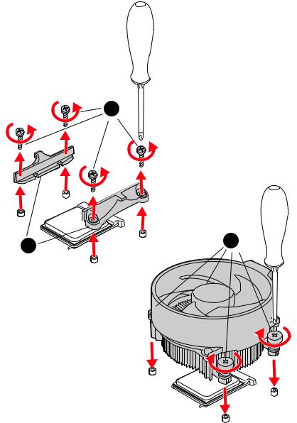
If you are installing the screw-type CPU heatsink, please follow the figure below to remove the retention module first and then install the heatsink.
1
4 Quick Start
Installing DDR4 memory
|
DIMMA2 |
DIMMA2 |
DIMMA1 |
|
DIMMA2 |
||
|
DIMMB2 |
DIMMB1 |
|
|
DIMMB2 |
Quick Start 5

Connecting the Front Panel Header
|
— |
|||
|
LED |
|||
|
LED+ |
POWER |
||
|
POWER |
|||
|
LED |
|||
|
SW |
HDD |
||
|
POWER |
|||
|
SW |
|||
|
RESET |
|
Power LED |
Power Switch |
||||||||||||||||||
|
-+-+ |
|||||||||||||||||||
|
JFP1 |
2 |
10 |
|||||||||||||||||
|
1 |
9 |
Reserved |
|||||||||||||||||
|
+ — +- |
|||||||||||||||||||
|
HDD LED |
Reset Switch |
||||||||||||||||||
|
1 |
HDD LED + |
2 |
Power LED + |
||||||||||||||||
|
3 |
HDD LED — |
4 |
Power LED — |
||||||||||||||||
|
5 |
Reset Switch |
6 |
Power Switch |
||||||||||||||||
|
7 |
Reset Switch |
8 |
Power Switch |
||||||||||||||||
|
9 |
Reserved |
10 |
No Pin |
HDDLED RESETSW
|
HDD LED — |
|||||||
|
HDD LED |
|||||||
|
HDD LED + |
|||||||
|
POWER LED — |
|||||||
|
POWER LED |
POWER LED + |
||||||
6 Quick Start

Installing the Motherboard
1
2
*3 kgf·cm = 0.3 N·m = 2.6 lbf·in
Quick Start 7
Connecting the Power Connectors
ATX_PWR1
CPU_PWR1
8 Quick Start
Installing SATA Drives
|
1 |
5
4
Quick Start 9
Installing a Graphics Card
1
5
 4
4
6
10 Quick Start
![]()
Connecting Peripheral Devices
|
Processor |
|
|
with |
|
|
Radeon™ |
Graphics |
Quick Start 11
12 Quick Start
|
Contents |
|
|
Quick Start……………………………………………………………………………………………….. |
1 |
|
Preparing Tools and Components……………………………………………………………….. |
1 |
|
Safety Information……………………………………………………………………………………… |
2 |
|
Installing a Processor………………………………………………………………………………… |
3 |
|
Installing DDR4 memory…………………………………………………………………………….. |
5 |
|
Connecting the Front Panel Header…………………………………………………………….. |
6 |
|
Installing the Motherboard…………………………………………………………………………. |
7 |
|
Connecting the Power Connectors………………………………………………………………. |
8 |
|
Installing SATA Drives………………………………………………………………………………… |
9 |
|
Installing a Graphics Card………………………………………………………………………… |
10 |
|
Connecting Peripheral Devices………………………………………………………………….. |
11 |
|
Power On………………………………………………………………………………………………… |
12 |
|
Specifications…………………………………………………………………………………………. |
15 |
|
Package contents……………………………………………………………………………………. |
20 |
|
Block Diagram ……………………………………………………………………………………….. |
21 |
|
Rear I/O Panel………………………………………………………………………………………… |
22 |
|
LAN Port LED Status Table……………………………………………………………………….. |
22 |
|
Audio Ports Configuration…………………………………………………………………………. |
22 |
|
Realtek Audio Console……………………………………………………………………………… |
23 |
|
Overview of Components…………………………………………………………………………. |
25 |
|
Processor Socket…………………………………………………………………………………….. |
27 |
|
DIMM Slots……………………………………………………………………………………………… |
28 |
|
PCI_E1~4: PCIe Expansion Slots……………………………………………………………….. |
29 |
|
SATA1~6: SATA 6Gb/s Connectors…………………………………………………………….. |
30 |
|
M2_1~2: M.2 Slots (Key M)………………………………………………………………………… |
30 |
|
JFP1, JFP2: Front Panel Connectors…………………………………………………………. |
32 |
|
JAUD1: Front Audio Connector………………………………………………………………….. |
32 |
|
CPU_PWR1, ATX_PWR1: Power Connectors……………………………………………….. |
33 |
|
JUSB4: USB 3.2 Gen 1 5Gbps Type-C Connector…………………………………………. |
34 |
|
JUSB3: USB 3.2 Gen 1 5Gbps Connector…………………………………………………….. |
34 |
|
JUSB1~2: USB 2.0 Connectors………………………………………………………………….. |
35 |
|
JTPM1: TPM Module Connector………………………………………………………………… |
35 |
|
CPU_FAN1, PUMP_FAN1, SYS_FAN1~6: Fan Connectors……………………………. |
36 |
|
JCI1: Chassis Intrusion Connector…………………………………………………………….. |
37 |
|
JCOM1: Serial Port Connector…………………………………………………………………… |
38 |
|
JBAT1: Clear CMOS (Reset BIOS) Jumper………………………………………………….. |
38 |
Contents 13
|
JRGB1: RGB LED connector……………………………………………………………………… |
39 |
|
JRAINBOW1~2: Addressable RGB LED connectors……………………………………… |
40 |
|
EZ Debug LED…………………………………………………………………………………………. |
41 |
|
LED_SW1: EZ LED Control………………………………………………………………………… |
41 |
|
Installing OS, Drivers & Utilities……………………………………………………………….. |
42 |
|
Installing Windows® 10……………………………………………………………………………… |
42 |
|
Installing Drivers……………………………………………………………………………………… |
42 |
|
Installing Utilities…………………………………………………………………………………….. |
42 |
|
UEFI BIOS………………………………………………………………………………………………. |
43 |
|
BIOS Setup……………………………………………………………………………………………… |
44 |
|
Entering BIOS Setup………………………………………………………………………………… |
44 |
|
Resetting BIOS………………………………………………………………………………………… |
45 |
|
Updating BIOS…………………………………………………………………………………………. |
45 |
|
EZ Mode………………………………………………………………………………………………….. |
47 |
|
Advanced Mode ………………………………………………………………………………………. |
50 |
|
SETTINGS Menu………………………………………………………………………………………. |
51 |
|
OC Menu…………………………………………………………………………………………………. |
53 |
|
M-FLASH Menu……………………………………………………………………………………….. |
55 |
|
OC PROFILE Menu……………………………………………………………………………………. |
56 |
|
HARDWARE MONITOR Menu…………………………………………………………………….. |
57 |
|
AMD RAID Configuration………………………………………………………………………….. |
59 |
|
Enabling RAIDXpert2 Configuration Utility………………………………………………….. |
59 |
|
Initializing Disks………………………………………………………………………………………. |
60 |
|
Creating Arrays……………………………………………………………………………………….. |
61 |
|
Deleting Arrays……………………………………………………………………………………….. |
62 |
|
Installing RAID Driver………………………………………………………………………………. |
63 |
|
Troubleshooting …………………………………………………………………………………….. |
64 |
14 Contents

Specifications
|
CPU |
Supports AM4 socket 3rd Gen AMD Ryzen™ processors, and |
|
future AMD Ryzen™ processors with BIOS update |
|
|
Chipset |
AMD B550 Chipset |
|
∙∙4x DDR4 memory slots, support up to 128GB* |
|
|
▪▪Supports DDR4 1866/ 2133/ 2400/ 2667/ 2800/ 2933/ |
|
|
3000/ 3066/ 3200 MHz by JEDEC |
|
|
▪▪Supports DDR4 2667/ 2800 /2933 /3000 /3066 /3200 |
|
|
/3466 /3600/ 3733 /3866 /4000 /4133 /4266 /4400+ MHz by |
|
|
A-XMP OC MODE |
|
|
▫▫1DPC 1R max speed 4400 MHz |
|
|
Memory |
▫▫1DPC 2R max speed 3866 MHz |
|
▫▫2DPC 1R max speed 4000 MHz |
|
|
▫▫2DPC 2R max speed 3600 MHz |
|
|
∙∙Dual channel memory architecture |
|
|
∙∙Supports non-ECC UDIMM memory |
|
|
∙∙Supports ECC UDIMM memory (non-ECC mode) |
|
|
∙∙Supports un-buffered memory |
|
|
* Please refer www.msi.com for more information on compatible memory. |
|
|
∙∙1x PCIe 4.0/ 3.0 x16 slot (PCI_E1)* |
|
|
Expansion Slot |
∙∙1x PCIe 3.0 x16 slot (PCI_E3), supports x4 speed** |
|
∙∙2x PCIe 3.0 x1 slots |
|
|
* The supported specification depends on installed processor. |
|
|
** When installing PCIe SSD in M.2_2, PCI_E3 slot will be unavailable. |
|
|
Multi-GPU |
∙∙Supports 2-Way AMD CrossFire™ Technology |
|
∙∙1x HDMI port, supports a maximum resolution of |
|
|
4096×2160 @24Hz* |
|
|
Onboard Graphics |
∙∙1x DisplayPort, supports a maximum resolution of |
|
4096×2160 @60Hz* |
|
|
∙∙Maximum shared memory of 2048 MB |
|
|
* Available for the processor with integrated graphics. |
|
|
Continued on next page |
Specifications 15

Continued from previous page
|
AMD B550 Chipset |
||
|
∙∙6x SATA 6Gb/s ports |
||
|
∙∙2x M.2 slots (Key M) |
||
|
▪▪M2_1 slot (from AMD Processor) |
||
|
Storage |
▫▫Supports PCIe 4.0/ 3.0 x4* |
|
|
▫▫Supports SATA 6Gb/s |
||
|
▫▫Supports 2242/ 2260/ 2280/ 22110 storage devices |
||
|
▪▪M2_2 slot (from AMD B550 chipset) |
||
|
▫▫Supports PCIe 3.0×4 |
||
|
▫▫Supports 2242/ 2260/ 2280 storage devices |
||
|
* The supported specification depends on installed processor. |
||
|
RAID |
∙∙Supports RAID 0, RAID 1 and RAID 10 for SATA storage |
|
|
devices |
||
|
∙∙Supports RAID 0 and RAID 1 for M.2 NVMe storage devices |
||
|
AMD B550 Chipset |
||
|
▪▪3x USB 3.2 Gen 1 5Gbps ports (1 Type-C internal |
||
|
connector, and 2 ports are available through the internal |
||
|
USB 3.2 Gen 1 5Gbps connector) |
||
|
USB |
▪▪8x USB 2.0 ports (4 Type-A ports on the back panel, 4 |
|
|
ports through the internal USB 2.0 connectors) |
||
|
AMD Processor |
||
|
▪▪2x USB 3.2 Gen 2 10Gbps ports (1 Type-C port and 1 |
||
|
Type-A port on the back panel) |
||
|
▪▪2x USB 3.2 Gen 1 5Gbps Type-A ports on the back |
||
|
panel |
||
|
Audio |
Realtek® ALC892 Codec |
|
|
▪▪7.1-Channel High Definition Audio |
||
|
LAN |
∙∙1x Realtek® 8111H Gigabit LAN controller |
|
|
Continued on next page |
16 Specifications

Continued from previous page
∙∙1x 24-pin ATX main power connector ∙∙1x 8-pin ATX 12V power connector ∙∙6x SATA 6Gb/s connectors
∙∙2x M.2 slots (M-Key)
∙∙1x USB 3.2 Gen 1 5Gbps Type-C port
∙∙1x USB 3.2 Gen 1 5Gbps connector (supports additional 2 USB 3.2 Gen 1 5Gbps ports)
∙∙2x USB 2.0 connectors (supports additional 4 USB 2.0 ports)
Internal Connectors ∙∙1x 4-pin CPU fan connector
∙∙1x 4-pin water-pump fan connector ∙∙6x 4-pin system fan connectors
∙∙1x Front panel audio connector ∙∙2x System panel connectors
∙∙1x Chassis Intrusion connector ∙∙1x 4-pin RGB LED connector
∙∙2x 3-pin RAINBOW LED connectors ∙∙1xTPM module connector
∙∙1x Clear CMOS jumper
|
LED Features |
∙∙1x EZ LED Control switch |
|||
|
∙∙4x EZ Debug LED |
||||
|
∙∙1x Flash BIOS Button |
||||
|
∙∙1x PS/2 keyboard/ mouse combo port |
||||
|
∙∙4x |
USB |
2.0 Type-A ports |
||
|
Back Panel |
∙∙1x |
Display port |
||
|
∙∙1x HDMI port |
||||
|
Connectors |
∙∙1x |
LAN (RJ45) port |
||
|
∙∙2x USB |
3.2 Gen 1 5Gbps Type-A ports |
|||
|
∙∙1x USB |
3.2 Gen 2 10Gbps Type-A port |
|||
|
∙∙1x USB |
3.2 Gen 2 10Gbps Type-C port |
|||
|
∙∙6x |
Audio jacks |
|||
|
I/O Controller |
NUVOTON NCT6687-R Controller Chip |
|||
|
Continued on next page |
Specifications 17

|
Continued from previous page |
|||
|
Hardware Monitor |
∙∙CPU/ System/ Chipset temperature detection |
||
|
∙∙CPU/ System/ Pump fan speed detection |
|||
|
∙∙CPU/ System/ Pump fan speed control |
|||
|
Form Factor |
∙∙ATX Form Factor |
||
|
∙∙12 in. x 9.6 in. (30.5 cm x 24.4 cm) |
|||
|
∙∙1x 256 Mb flash |
|||
|
BIOS Features |
∙∙UEFI AMI BIOS |
||
|
∙∙ACPI 6.0, SMBIOS 2.8 |
|||
|
∙∙Multi-language |
|||
|
∙∙Drivers |
|||
|
∙∙DRAGON CENTER |
|||
|
Software |
∙∙MSI APP Player (BlueStacks) |
||
|
∙∙Open Broadcaster Software (OBS) |
|||
|
∙∙CPU-Z MSI GAMING |
|||
|
∙∙Google Chrome™, Google Toolbar, Google Drive |
|||
|
∙∙Norton™ Internet Security Solution |
|||
|
∙∙Gaming Mode |
|||
|
∙∙Gaming Hotkey |
|||
|
∙∙LAN Manager |
|||
|
Dragon Center |
∙∙Mystic Light |
||
|
∙∙Hardware Monitor |
|||
|
Features |
∙∙True Color |
||
|
∙∙Live Update |
Please refer to http://download.msi. |
||
|
∙∙Speed Up |
com/manual/mb/DRAGONCENTER2. |
||
|
pdf for more details. |
|||
|
∙∙Smart Tool |
|||
|
∙∙Super Charger |
|||
|
Continued on next page |
18 Specifications

Continued from previous page
∙∙Audio
▪▪Audio Boost ∙∙Storage
▪▪Lightning Gen4 M.2 ∙∙Cooling
▪▪All Aluminum Design
▪▪Extended Heatsink Design
▪▪Pump Fan
▪▪Smart Fan Control
∙∙LED
▪▪Mystic Light Extension (RAINBOW/RGB)
▪▪Mystic Light SYNC
▪▪Ambient Link
▪▪EZ LED Control
▪▪EZ DEBUG LED ∙∙Protection
Special Features ▪▪M.2 Shield
▪▪PCI-E Steel Armor
▪▪PCI-E Steel Slot
∙∙Performance
▪▪Lightning Gen 4 PCI-E Slot
▪▪Lightning Gen 4 M.2
▪▪Multi GPU-CrossFire Technology
▪▪DDR4 Boost
▪▪Core Boost
▪▪GAME Boost ▪▪USB with Type A+C ▪▪USB 3.2 Gen 2 ▪▪Front USB Type-C
∙∙Experience ▪▪Dragon Center ▪▪Click BIOS 5 ▪▪Flash BIOS Button
Specifications 19
Package contents
Please check the contents of your motherboard package. It should contain:
|
Motherboard |
B550-A PRO |
|
|
Cable |
SATA 6G cables (2 cables/pack) |
1 |
|
Accessories |
M.2 screws (3 pcs./pack) |
1 |
|
Case badge |
1 |
|
|
Product registration card |
1 |
|
|
Application |
Driver DVD |
1 |
|
Documentation |
Quick installation guide |
1 |
|
MSI components compatibility & reward program |
1 |
|
|
card |
Important
If any of the above items are damaged or missing, please contact your retailer.
20 Package contents
![]()
Block Diagram
|
2 Channel DDR4 Memory |
||||
|
Processor |
||||
|
1x M.2 |
||||
|
2x USB 3.2 Gen1 |
||||
|
1x M.2 |
Switch |
2x USB 3.2 Gen2 |
||
|
PCIE |
||||
|
6x SATA 6Gb/s |
Realtek Front Audio Jacks |
|||
|
ALC892 |
Rear Audio Jacks |
|||
|
NUVOTON |
||||
|
PCH |
6687 |
|||
|
8x USB 2.0 |
2x PCIe x1 slots |
3x USB 3.2 Gen1
1x Realtek 8111H LAN
Block Diagram 21
 Loading…
View a manual of the MSI B550-A Pro below. All manuals on ManualsCat.com can be viewed completely free of charge. By using the ‘Select a language’ button, you can choose the language of the manual you want to view.
Page: 1
1
Quick Start
Quick Start
Thank you for purchasing the MSI® B550-A PRO motherboard. This Quick Start
section provides demonstration diagrams about how to install your computer. Some
of the installations also provide video demonstrations. Please link to the URL to watch
it with the web browser on your phone or tablet. You may have even link to the URL by
scanning the QR code.
Preparing Tools and Components
DDR4 Memory
Graphics Card
SATA Hard Disk Drive
SATA DVD Drive
Phillips Screwdriver
Chassis
Power Supply Unit
A Package of Screws
Thermal Paste
CPU Fan
AMD®
AM4 CPU
Page: 2
2 Quick Start
Safety Information
∙
∙ The components included in this package are prone to damage from electrostatic
discharge (ESD). Please adhere to the following instructions to ensure successful
computer assembly.
∙
∙ Ensure that all components are securely connected. Loose connections may cause
the computer to not recognize a component or fail to start.
∙
∙ Hold the motherboard by the edges to avoid touching sensitive components.
∙
∙ It is recommended to wear an electrostatic discharge (ESD) wrist strap when
handling the motherboard to prevent electrostatic damage. If an ESD wrist strap is
not available, discharge yourself of static electricity by touching another metal object
before handling the motherboard.
∙
∙ Store the motherboard in an electrostatic shielding container or on an anti-static
pad whenever the motherboard is not installed.
∙
∙ Before turning on the computer, ensure that there are no loose screws or metal
components on the motherboard or anywhere within the computer case.
∙
∙ Do not boot the computer before installation is completed. This could cause
permanent damage to the components as well as injury to the user.
∙
∙ If you need help during any installation step, please consult a certified computer
technician.
∙
∙ Always turn off the power supply and unplug the power cord from the power outlet
before installing or removing any computer component.
∙
∙ Keep this user guide for future reference.
∙
∙ Keep this motherboard away from humidity.
∙
∙ Make sure that your electrical outlet provides the same voltage as is indicated on
the PSU, before connecting the PSU to the electrical outlet.
∙
∙ Place the power cord such a way that people can not step on it. Do not place
anything over the power cord.
∙
∙ All cautions and warnings on the motherboard should be noted.
∙
∙ If any of the following situations arises, get the motherboard checked by service
personnel:
▪
▪ Liquid has penetrated into the computer.
▪
▪ The motherboard has been exposed to moisture.
▪
▪ The motherboard does not work well or you can not get it work according to user
guide.
▪
▪ The motherboard has been dropped and damaged.
▪
▪ The motherboard has obvious sign of breakage.
∙
∙ Do not leave this motherboard in an environment above 60°C (140°F), it may damage
the motherboard.
Page: 3
3
Quick Start
Installing a Processor
1
2
3
6
4
5
7
8
9
Page: 4
4 Quick Start
1
2
3
⚠
⚠Important
If you are installing the screw-type CPU heatsink, please follow the figure below to
remove the retention module first and then install the heatsink.
Page: 5
5
Quick Start
Installing DDR4 memory
DIMMA2 DIMMA2
DIMMB2
DIMMA1
DIMMA2
DIMMB1
DIMMB2
Page: 6
6 Quick Start
HDD
LED
RESET
SW
Connecting the Front Panel Header
JFP1
HDD LED
HDD LED —
HDD LED +
POWER LED —
POWER LED +
POWER LED
1
2 10
9
+
+
+
—
—
—
—
+
Power LED
HDD LED Reset Switch
Reserved
Power Switch
JFP1
1 HDD LED + 2 Power LED +
3 HDD LED — 4 Power LED —
5 Reset Switch 6 Power Switch
7 Reset Switch 8 Power Switch
9 Reserved 10 No Pin
R
E
S
E
T
S
W
P
O
W
E
R
S
W
P
O
W
E
R
L
E
D
+ P
O
W
E
R
L
E
D
—
H
D
D
L
E
D
Page: 7
7
Quick Start
Installing the Motherboard
3
⚽
⚽
Torque:
3 kgf·cm*
*3 kgf·cm
= 0.3 N·m
= 2.6 lbf·in
2
1
Page: 8
8 Quick Start
Connecting the Power Connectors
ATX_PWR1
CPU_PWR1
Page: 9
9
Quick Start
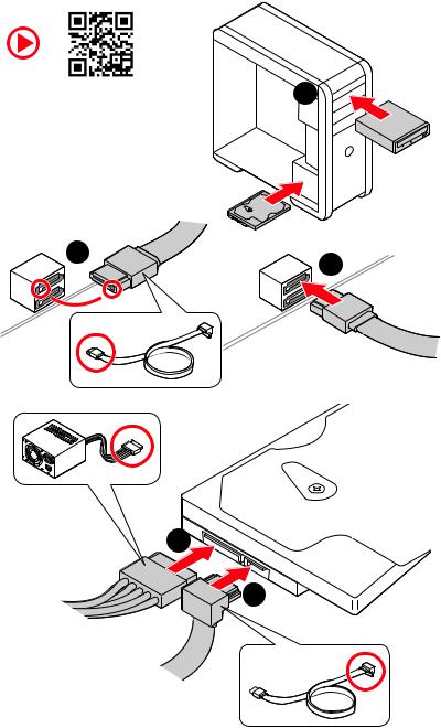
Installing SATA Drives
1
2
3
4
5
Page: 10
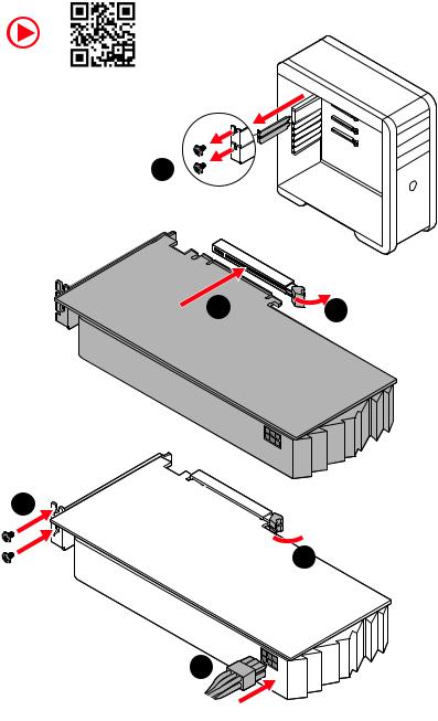
10 Quick Start
1
Installing a Graphics Card
2
3
4
5
6
Page: 11
11
Quick Start
Connecting Peripheral Devices
Processor with Radeon™ Graphics
Page: 12
12 Quick Start
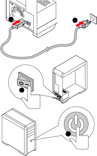
Power On
4
3
1 2
Page: 13
13
Contents
Contents
Quick Start……………………………………………………………………………………………….. 1
Preparing Tools and Components……………………………………………………………….. 1
Safety Information……………………………………………………………………………………… 2
Installing a Processor………………………………………………………………………………… 3
Installing DDR4 memory…………………………………………………………………………….. 5
Connecting the Front Panel Header…………………………………………………………….. 6
Installing the Motherboard………………………………………………………………………….. 7
Connecting the Power Connectors………………………………………………………………. 8
Installing SATA Drives………………………………………………………………………………… 9
Installing a Graphics Card…………………………………………………………………………. 10
Connecting Peripheral Devices………………………………………………………………….. 11
Power On………………………………………………………………………………………………… 12
Specifications………………………………………………………………………………………….. 15
Package contents……………………………………………………………………………………. 20
Block Diagram ……………………………………………………………………………………….. 21
Rear I/O Panel………………………………………………………………………………………… 22
LAN Port LED Status Table……………………………………………………………………….. 22
Audio Ports Configuration…………………………………………………………………………. 22
Realtek Audio Console……………………………………………………………………………… 23
Overview of Components…………………………………………………………………………. 25
Processor Socket…………………………………………………………………………………….. 27
DIMM Slots………………………………………………………………………………………………. 28
PCI_E1~4: PCIe Expansion Slots………………………………………………………………… 29
SATA1~6: SATA 6Gb/s Connectors……………………………………………………………… 30
M2_1~2: M.2 Slots (Key M)………………………………………………………………………… 30
JFP1, JFP2: Front Panel Connectors………………………………………………………….. 32
JAUD1: Front Audio Connector………………………………………………………………….. 32
CPU_PWR1, ATX_PWR1: Power Connectors……………………………………………….. 33
JUSB4: USB 3.2 Gen 1 5Gbps Type-C Connector………………………………………….. 34
JUSB3: USB 3.2 Gen 1 5Gbps Connector…………………………………………………….. 34
JUSB1~2: USB 2.0 Connectors…………………………………………………………………… 35
JTPM1: TPM Module Connector…………………………………………………………………. 35
CPU_FAN1, PUMP_FAN1, SYS_FAN1~6: Fan Connectors…………………………….. 36
JCI1: Chassis Intrusion Connector……………………………………………………………… 37
JCOM1: Serial Port Connector…………………………………………………………………… 38
JBAT1: Clear CMOS (Reset BIOS) Jumper…………………………………………………… 38
Page: 14
14 Contents
JRGB1: RGB LED connector………………………………………………………………………. 39
JRAINBOW1~2: Addressable RGB LED connectors……………………………………… 40
EZ Debug LED………………………………………………………………………………………….. 41
LED_SW1: EZ LED Control………………………………………………………………………… 41
Installing OS, Drivers & Utilities……………………………………………………………….. 42
Installing Windows® 10……………………………………………………………………………… 42
Installing Drivers……………………………………………………………………………………… 42
Installing Utilities…………………………………………………………………………………….. 42
UEFI BIOS……………………………………………………………………………………………….. 43
BIOS Setup………………………………………………………………………………………………. 44
Entering BIOS Setup…………………………………………………………………………………. 44
Resetting BIOS…………………………………………………………………………………………. 45
Updating BIOS………………………………………………………………………………………….. 45
EZ Mode………………………………………………………………………………………………….. 47
Advanced Mode ……………………………………………………………………………………….. 50
SETTINGS Menu………………………………………………………………………………………. 51
OC Menu…………………………………………………………………………………………………. 53
M-FLASH Menu……………………………………………………………………………………….. 55
OC PROFILE Menu……………………………………………………………………………………. 56
HARDWARE MONITOR Menu…………………………………………………………………….. 57
AMD RAID Configuration………………………………………………………………………….. 59
Enabling RAIDXpert2 Configuration Utility………………………………………………….. 59
Initializing Disks………………………………………………………………………………………. 60
Creating Arrays……………………………………………………………………………………….. 61
Deleting Arrays………………………………………………………………………………………… 62
Installing RAID Driver……………………………………………………………………………….. 63
Troubleshooting …………………………………………………………………………………….. 64
Page: 15
15
Specifications
Specifications
CPU
Supports AM4 socket 3rd Gen AMD Ryzen™ processors, and
future AMD Ryzen™ processors with BIOS update
Chipset AMD B550 Chipset
Memory
∙
∙ 4x DDR4 memory slots, support up to 128GB*
▪
▪ Supports DDR4 1866/ 2133/ 2400/ 2667/ 2800/ 2933/
3000/ 3066/ 3200 MHz by JEDEC
▪
▪ Supports DDR4 2667/ 2800 /2933 /3000 /3066 /3200
/3466 /3600/ 3733 /3866 /4000 /4133 /4266 /4400+ MHz by
A-XMP OC MODE
▫
▫ 1DPC 1R max speed 4400 MHz
▫
▫ 1DPC 2R max speed 3866 MHz
▫
▫ 2DPC 1R max speed 4000 MHz
▫
▫ 2DPC 2R max speed 3600 MHz
∙
∙ Dual channel memory architecture
∙
∙ Supports non-ECC UDIMM memory
∙
∙ Supports ECC UDIMM memory (non-ECC mode)
∙
∙ Supports un-buffered memory
* Please refer www.msi.com for more information on compatible memory.
Expansion Slot
∙
∙ 1x PCIe 4.0/ 3.0 x16 slot (PCI_E1)*
∙
∙ 1x PCIe 3.0 x16 slot (PCI_E3), supports x4 speed**
∙
∙ 2x PCIe 3.0 x1 slots
* The supported specification depends on installed processor.
** When installing PCIe SSD in M.2_2, PCI_E3 slot will be unavailable.
Multi-GPU ∙
∙ Supports 2-Way AMD CrossFire™ Technology
Onboard Graphics
∙
∙ 1x HDMI port, supports a maximum resolution of
4096×2160 @24Hz*
∙
∙ 1x DisplayPort, supports a maximum resolution of
4096×2160 @60Hz*
∙
∙ Maximum shared memory of 2048 MB
* Available for the processor with integrated graphics.
Continued on next page
Page: 16
16 Specifications
Continued from previous page
Storage
AMD B550 Chipset
∙
∙ 6x SATA 6Gb/s ports
∙
∙ 2x M.2 slots (Key M)
▪
▪ M2_1 slot (from AMD Processor)
▫
▫ Supports PCIe 4.0/ 3.0 x4*
▫
▫ Supports SATA 6Gb/s
▫
▫ Supports 2242/ 2260/ 2280/ 22110 storage devices
▪
▪ M2_2 slot (from AMD B550 chipset)
▫
▫ Supports PCIe 3.0×4
▫
▫ Supports 2242/ 2260/ 2280 storage devices
* The supported specification depends on installed processor.
RAID
∙
∙ Supports RAID 0, RAID 1 and RAID 10 for SATA storage
devices
∙
∙ Supports RAID 0 and RAID 1 for M.2 NVMe storage devices
USB
AMD B550 Chipset
▪
▪ 3x USB 3.2 Gen 1 5Gbps ports (1 Type-C internal
connector, and 2 ports are available through the internal
USB 3.2 Gen 1 5Gbps connector)
▪
▪ 8x USB 2.0 ports (4 Type-A ports on the back panel, 4
ports through the internal USB 2.0 connectors)
AMD Processor
▪
▪ 2x USB 3.2 Gen 2 10Gbps ports (1 Type-C port and 1
Type-A port on the back panel)
▪
▪ 2x USB 3.2 Gen 1 5Gbps Type-A ports on the back
panel
Audio
Realtek® ALC892 Codec
▪
▪ 7.1-Channel High Definition Audio
LAN ∙
∙ 1x Realtek® 8111H Gigabit LAN controller
Continued on next page
Page: 17
17
Specifications
Continued from previous page
Internal Connectors
∙
∙ 1x 24-pin ATX main power connector
∙
∙ 1x 8-pin ATX 12V power connector
∙
∙ 6x SATA 6Gb/s connectors
∙
∙ 2x M.2 slots (M-Key)
∙
∙ 1x USB 3.2 Gen 1 5Gbps Type-C port
∙
∙ 1x USB 3.2 Gen 1 5Gbps connector (supports additional 2
USB 3.2 Gen 1 5Gbps ports)
∙
∙ 2x USB 2.0 connectors (supports additional 4 USB 2.0
ports)
∙
∙ 1x 4-pin CPU fan connector
∙
∙ 1x 4-pin water-pump fan connector
∙
∙ 6x 4-pin system fan connectors
∙
∙ 1x Front panel audio connector
∙
∙ 2x System panel connectors
∙
∙ 1x Chassis Intrusion connector
∙
∙ 1x 4-pin RGB LED connector
∙
∙ 2x 3-pin RAINBOW LED connectors
∙
∙ 1xTPM module connector
∙
∙ 1x Clear CMOS jumper
LED Features
∙
∙ 1x EZ LED Control switch
∙
∙ 4x EZ Debug LED
Back Panel
Connectors
∙
∙ 1x Flash BIOS Button
∙
∙ 1x PS/2 keyboard/ mouse combo port
∙
∙ 4x USB 2.0 Type-A ports
∙
∙ 1x Display port
∙
∙ 1x HDMI port
∙
∙ 1x LAN (RJ45) port
∙
∙ 2x USB 3.2 Gen 1 5Gbps Type-A ports
∙
∙ 1x USB 3.2 Gen 2 10Gbps Type-A port
∙
∙ 1x USB 3.2 Gen 2 10Gbps Type-C port
∙
∙ 6x Audio jacks
I/O Controller NUVOTON NCT6687-R Controller Chip
Continued on next page
Page: 18
18 Specifications
Continued from previous page
Hardware Monitor
∙
∙ CPU/ System/ Chipset temperature detection
∙
∙ CPU/ System/ Pump fan speed detection
∙
∙ CPU/ System/ Pump fan speed control
Form Factor
∙
∙ ATX Form Factor
∙
∙ 12 in. x 9.6 in. (30.5 cm x 24.4 cm)
BIOS Features
∙
∙ 1x 256 Mb flash
∙
∙ UEFI AMI BIOS
∙
∙ ACPI 6.0, SMBIOS 2.8
∙
∙ Multi-language
Software
∙
∙ Drivers
∙
∙ DRAGON CENTER
∙
∙ MSI APP Player (BlueStacks)
∙
∙ Open Broadcaster Software (OBS)
∙
∙ CPU-Z MSI GAMING
∙
∙ Google Chrome™, Google Toolbar, Google Drive
∙
∙ Norton™ Internet Security Solution
Dragon Center
Features
∙
∙ Gaming Mode
∙
∙ Gaming Hotkey
∙
∙ LAN Manager
∙
∙ Mystic Light
∙
∙ Hardware Monitor
∙
∙ True Color
∙
∙ Live Update
∙
∙ Speed Up
∙
∙ Smart Tool
∙
∙ Super Charger
Please refer to http://download.msi.
com/manual/mb/DRAGONCENTER2.
pdf for more details.
Continued on next page
Page: 19
19
Specifications
Continued from previous page
Special Features
∙
∙ Audio
▪
▪ Audio Boost
∙
∙ Storage
▪
▪ Lightning Gen4 M.2
∙
∙ Cooling
▪
▪ All Aluminum Design
▪
▪ Extended Heatsink Design
▪
▪ Pump Fan
▪
▪ Smart Fan Control
∙
∙ LED
▪
▪ Mystic Light Extension (RAINBOW/RGB)
▪
▪ Mystic Light SYNC
▪
▪ Ambient Link
▪
▪ EZ LED Control
▪
▪ EZ DEBUG LED
∙
∙ Protection
▪
▪ M.2 Shield
▪
▪ PCI-E Steel Armor
▪
▪ PCI-E Steel Slot
∙
∙ Performance
▪
▪ Lightning Gen 4 PCI-E Slot
▪
▪ Lightning Gen 4 M.2
▪
▪ Multi GPU-CrossFire Technology
▪
▪ DDR4 Boost
▪
▪ Core Boost
▪
▪ GAME Boost
▪
▪ USB with Type A+C
▪
▪ USB 3.2 Gen 2
▪
▪ Front USB Type-C
∙
∙ Experience
▪
▪ Dragon Center
▪
▪ Click BIOS 5
▪
▪ Flash BIOS Button
Page: 20
20 Package contents
Package contents
Please check the contents of your motherboard package. It should contain:
Motherboard B550-A PRO
Cable SATA 6G cables (2 cables/pack) 1
Accessories
M.2 screws (3 pcs./pack) 1
Case badge 1
Product registration card 1
Application Driver DVD 1
Documentation
Quick installation guide 1
MSI components compatibility & reward program
card
1
⚠
⚠Important
If any of the above items are damaged or missing, please contact your retailer.
Page: 21
21
Block Diagram
Block Diagram
2 Channel DDR4 Memory
2x USB 3.2 Gen1
PCIE
PCH
Processor
NUVOTON
6687
Realtek
ALC892
3x USB 3.2 Gen1
8x USB 2.0
Rear Audio Jacks
Front Audio Jacks
1x M.2
6x SATA 6Gb/s
1x M.2
2x USB 3.2 Gen2
1x Realtek 8111H LAN
2x PCIe x1 slots
Switch
Page: 22
22 Rear I/O Panel
USB 3.2 Gen 1
(5Gbps) Type-A
Flash BIOS
Port
Rear I/O Panel
PS/2 Combo port
1 Gbps LAN
DisplayPort
USB 2.0
Type-A
USB 2.0
Type-A
Audio Ports
USB 3.2 Gen 2
(10Gbps) Type-C
USB 3.2 Gen 2
(10Gbps) Type-A
∙
∙ Flash BIOS Port/ Button — Please refer to page 46 for Updating BIOS with Flash
BIOS Button.
Flash BIOS
Button
Link/ Activity LED
Status Description
Off No link
Yellow Linked
Blinking Data activity
Speed LED
Status Description
Off 10 Mbps connection
Green 100 Mbps connection
Orange 1 Gbps connection
LAN Port LED Status Table
Audio Ports Configuration
Audio Ports
Channel
2 4 6 8
Line-In
Line-Out/ Front Speaker Out ● ● ● ●
Rear Speaker Out ● ● ●
Center/ Subwoofer Out ● ●
Side Speaker Out ●
Mic In
(●: connected, Blank: empty)
Page: 23
23
Rear I/O Panel
∙
∙ Device Selection — allows you to select a audio output source to change the related
options. The check sign indicates the devices as default.
∙
∙ Application Enhancement — the array of options will provide you a complete
guidance of anticipated sound effect for both output and input device.
∙
∙ Main Volume — controls the volume or balance the right/left side of the speakers
that you plugged in front or rear panel by adjust the bar.
∙
∙ Jack Status — depicts all render and capture devices currently connected with your
computer.
∙
∙ Connector Settings — configures the connection settings.
Auto popup dialog
When you plug into a device at an audio jack, a dialogue window will pop up asking you
which device is current connected.
Each jack corresponds to its default setting as shown on the next page.
⚠
⚠Important
The pictures above for reference only and may vary from the product you purchased.
Realtek Audio Console
After Realtek Audio Console is installed. You can use it to change sound settings to get
better sound experience.
Jack Status
Connector Settings
Device
Selection
Main Volume
Application Enhancement
Page: 24
24 Rear I/O Panel
AUDIO INPUT
Rear
Front
Side
Center/
Subwoofer
AUDIO INPUT
Audio jacks to headphone and microphone diagram
Audio jacks to stereo speakers diagram
Audio jacks to 7.1-channel speakers diagram
Page: 25
25
Overview of Components
Overview of Components
JUSB3
SYS_FAN3
JRGB1
JCOM1
SATA▼5▲6
SATA▼1▲2
SATA▼3▲4
M2_2
M2_1
SYS_FAN6
JTPM1
JUSB4
JUSB2
JUSB1
SYS_FAN4
SYS_FAN5
CPU_FAN1
SYS_FAN2
SYS_FAN1
PCI_E1
PCI_E2
PCI_E3
JBAT1
PCI_E4
Processor Socket
CPU_PWR1
PUMP_FAN1
JRAINBOW2
JAUD1
JCI1
JFP1
JRAINBOW1
LED_SW1
JFP2
ATX_PWR1
DIMMB1
DIMMB2
DIMMA1
Page: 26
26 Overview of Components
Component Contents
Port Name Port Type Page
CPU_FAN1, PUMP_FAN1,
SYS_FAN1~6
Fan Connectors 36
CPU_PWR1, ATX_PWR1 Power Connectors 33
DIMMA1, DIMMA2,
DIMMB1, DIMMB2
DIMM Slots 28
JAUD1 Front Audio Connector 32
JBAT1 Clear CMOS (Reset BIOS) Jumper 38
JCI1 Chassis Intrusion Connector 37
JCOM1 Serial Port Connector 38
JFP1, JFP2 Front Panel Connectors 32
JRAINBOW1~2 Addressable RGB LED connectors 40
JRGB1 RGB LED connector 39
JTPM1 TPM Module Connector 35
JUSB1~2 USB 2.0 Connectors 35
JUSB3 USB 3.2 Gen 1 5Gbps Connector 34
JUSB4 USB 3.2 Gen 1 5Gbps Type-C Connector 34
LED_SW1 EZ LED Control 41
M2_1~2 M.2 Slots (Key M) 30
PCI_E1~4 PCIe Expansion Slots 29
Processor Socket Socket AM4 27
SATA1~6 SATA 6Gb/s Connectors 30
Page: 27
27
Overview of Components
Processor Socket
Introduction to the AM4 CPU
The surface of the AM4 CPU has a
yellow triangle to assist in correctly
lining up the CPU for motherboard
placement. The yellow triangle is
the Pin 1 indicator.
53.8 mm
Distance from the center of the
CPU to the nearest DIMM slot.
⚠
⚠Important
∙
∙ When changing the processor, the system configuration could be cleared and reset
BIOS to default values, due to the AM4 processor’s architecture.
∙
∙ Always unplug the power cord from the power outlet before installing or removing
the CPU.
∙
∙ When installing a CPU, always remember to install a CPU heatsink. A CPU heatsink
is necessary to prevent overheating and maintain system stability.
∙
∙ Confirm that the CPU heatsink has formed a tight seal with the CPU before booting
your system.
∙
∙ Overheating can seriously damage the CPU and motherboard. Always make sure
the cooling fans work properly to protect the CPU from overheating. Be sure to apply
an even layer of thermal paste (or thermal tape) between the CPU and the heatsink to
enhance heat dissipation.
∙
∙ If you purchased a separate CPU and heatsink/ cooler, Please refer to the
documentation in the heatsink/ cooler package for more details about installation.
∙
∙ This motherboard is designed to support overclocking. Before attempting to
overclock, please make sure that all other system components can tolerate
overclocking. Any attempt to operate beyond product specifications is not
recommended. MSI® does not guarantee the damages or risks caused by inadequate
operation beyond product specifications.
Page: 28
28 Overview of Components
DIMM Slots
DIMMA1 DIMMB1
Channel A Channel B
DIMMA2 DIMMB2
Memory module installation recommendation
⚠
⚠Important
∙
∙ Always insert memory modules in the DIMMA2 slot first.
∙
∙ Due to chipset resource usage, the available capacity of memory will be a little less
than the amount of installed.
∙
∙ Based on CPU specification, the Memory DIMM voltage below 1.35V is suggested to
protect the CPU.
∙
∙ To ensure system stability for Dual channel mode, memory modules must be of the
same type, number and density.
∙
∙ Some memory modules may operate at a lower frequency than the marked value
when overclocking due to the memory frequency operates dependent on its Serial
Presence Detect (SPD). Go to BIOS and find the DRAM Frequency to set the memory
frequency if you want to operate the memory at the marked or at a higher frequency.
∙
∙ It is recommended to use a more efficient memory cooling system for full DIMMs
installation or overclocking.
∙
∙ The stability and compatibility of installed memory module depend on installed CPU
and devices when overclocking.
∙
∙ Please refer www.msi.com for more information on compatible memory.
DIMMB2 DIMMB2
DIMMB1
DIMMA2 DIMMA2 DIMMA2
DIMMA1
Page: 29
29
Overview of Components
PCI_E1~4: PCIe Expansion Slots
⚠
⚠Important
∙
∙ If you install a large and heavy graphics card, you need to use a tool such as MSI
Gaming Series Graphics Card Bolster to support its weight to prevent deformation of
the slot.
∙
∙ For a single PCIe x16 expansion card installation with optimum performance, using
the PCI_E1 slot is recommended.
∙
∙ When adding or removing expansion cards, always turn off the power supply and
unplug the power supply power cable from the power outlet. Read the expansion
card’s documentation to check for any necessary additional hardware or software
changes.
∙
∙ When installing PCIe SSD in M.2_2, PCI_E3 slot will be unavailable.
M.2 slots and PCIe slots combination table
Slot Combination
M2_1 (CPU) PCIe/SATA
M2_2 (PCH) PCIe x4 ─
PCI_E1 (CPU) ✓ ✓
PCI_E2 (PCH) ✓ ✓
PCI_E3 (PCH) ─ ✓
PCI_E4 (PCH) ✓ ✓
(SATA: M.2 SATA SSD, PCIe: M.2 PCIe SSD, ✓: available, ─: unavailable)
PCI_E1: PCIe 3.0/ 4.0 x16 (CPU)
PCI_E3: PCIe 3.0 x4 (PCH)
PCI_E2: PCIe 3.0 x1 (PCH)
PCI_E4: PCIe 3.0 x1 (PCH)
Page: 30
30 Overview of Components
M2_1~2: M.2 Slots (Key M)
M2_1
M2_2
SATA1~6: SATA 6Gb/s Connectors
These connectors are SATA 6Gb/s interface ports. Each connector can connect to one
SATA device.
⚠
⚠Important
∙
∙ Please do not fold the SATA cable at a 90-degree angle. Data loss may result during
transmission otherwise.
∙
∙ SATA cables have identical plugs on either sides of the cable. However, it is
recommended that the flat connector be connected to the motherboard for space
saving purposes.
SATA5
SATA1
SATA3
SATA6
SATA2
SATA4
M2_1 slot installation
1. Loosen the screws of M.2 SHIELD FROZR heatsink.
2. Remove the M.2 SHIELD FROZR and remove the protective films from the thermal
pads.
⚽
⚽Video Demonstration
Watch the video to learn how to Install
M.2 module.
Page: 31
31
Overview of Components
1
1
2
30º
30º
M.2 standoff
heatsink standoff
3
5
4
M.2 screw
6
6
M2_2 slot installation
Please follows the step3, 4 and 5 above to install the M.2 SSD to the M2_2 slot.
3. Move and fasten the M.2 standoff to the appropriate position for your M.2 SSD,
or remove the M.2 standoff if your M.2 SSD length is same as the length of M.2
heatsink to avoid damage to the M.2 SSD.
4. Insert your M.2 SSD into the M.2 slot at a 30-degree angle.
5. Secure the M.2 SSD in place with the M.2 screw, or skip this step if you remove the
M.2 standoff in step 3.
6. Put the M.2 SHIELD FROZR heatsink back in place and secure it.
Page: 32
32 Overview of Components
JAUD1: Front Audio Connector
This connector allows you to connect audio jacks on the front panel.
1
2 10
9
1 MIC L 2 Ground
3 MIC R 4 NC
5 Head Phone R 6 MIC Detection
7 SENSE_SEND 8 No Pin
9 Head Phone L 10 Head Phone Detection
JFP1, JFP2: Front Panel Connectors
These connectors connect to the switches and LEDs on the front panel.
1
JFP2
+
+
—
—
Speaker
Buzzer 1 Speaker — 2 Buzzer +
3 Buzzer — 4 Speaker +
1
2 10
9
+
+
+
—
—
—
—
+
Power LED
HDD LED Reset Switch
Reserved
Power Switch
JFP1
1 HDD LED + 2 Power LED +
3 HDD LED — 4 Power LED —
5 Reset Switch 6 Power Switch
7 Reset Switch 8 Power Switch
9 Reserved 10 No Pin
Page: 33
33
Overview of Components
24
13
1
12
ATX_PWR1
1 +3.3V 13 +3.3V
2 +3.3V 14 -12V
3 Ground 15 Ground
4 +5V 16 PS-ON#
5 Ground 17 Ground
6 +5V 18 Ground
7 Ground 19 Ground
8 PWR OK 20 Res
9 5VSB 21 +5V
10 +12V 22 +5V
11 +12V 23 +5V
12 +3.3V 24 Ground
5
4 1
8
CPU_PWR1
1 Ground 5 +12V
2 Ground 6 +12V
3 Ground 7 +12V
4 Ground 8 +12V
⚠
⚠Important
Make sure that all the power cables are securely connected to a proper ATX power
supply to ensure stable operation of the motherboard.
CPU_PWR1, ATX_PWR1: Power Connectors
These connectors allow you to connect an ATX power supply.
Page: 34
34 Overview of Components
JUSB4: USB 3.2 Gen 1 5Gbps Type-C Connector
This connector allows you to connect USB 3.2 Gen 1 5Gbps Type-C connector on the
front panel. The connector possesses a foolproof design. When you connect the cable,
be sure to connect it with the corresponding orientation.
JUSB3: USB 3.2 Gen 1 5Gbps Connector
This connector allows you to connect USB 3.2 Gen 1 5Gbps ports on the front panel.
⚠
⚠Important
Note that the Power and Ground pins must be connected correctly to avoid possible
damage.
1 10
11
20
1 Power 11 USB2.0+
2 USB3_RX_DN 12 USB2.0-
3 USB3_RX_DP 13 Ground
4 Ground 14 USB3_TX_C_DP
5 USB3_TX_C_DN 15 USB3_TX_C_DN
6 USB3_TX_C_DP 16 Ground
7 Ground 17 USB3_RX_DP
8 USB2.0- 18 USB3_RX_DN
9 USB2.0+ 19 Power
10 Ground 20 No Pin
JUSB4
USB Type-C Cable
USB Type-C port on
the front panel
Page: 35
35
Overview of Components
JUSB1~2: USB 2.0 Connectors
These connectors allow you to connect USB 2.0 ports on the front panel.
1
2 10
9
1 VCC 2 VCC
3 USB0- 4 USB1-
5 USB0+ 6 USB1+
7 Ground 8 Ground
9 No Pin 10 NC
⚠
⚠Important
∙
∙ Note that the VCC and Ground pins must be connected correctly to avoid possible
damage.
∙
∙ In order to recharge your iPad,iPhone and iPod through USB ports, please install
MSI® DRAGON CENTER utility.
1
2
12 11
1 SPI Power 2 SPI Chip Select
3 Master In Slave Out (SPI Data) 4 Master In Slave In (SPI Data)
5 Reserved 6 SPI Clock
7 Ground 8 SPI Reset
9 Reserved 10 No Pin
11 Reserved 12 Interrupt Request
JTPM1: TPM Module Connector
This connector is for TPM (Trusted Platform Module). Please refer to the TPM security
platform manual for more details and usages.
Page: 36
36 Overview of Components
CPU_FAN1, PUMP_FAN1, SYS_FAN1~6: Fan Connectors
Fan connectors can be classified as PWM (Pulse Width Modulation) Mode or DC Mode.
PWM Mode fan connectors provide constant 12V output and adjust fan speed with
speed control signal. DC Mode fan connectors control fan speed by changing voltage.
The auto mode fan connectors can automatically detect PWM and DC mode. However,
you can follow the instruction below to adjust the fan connector to PWM or DC Mode
manually.
Switching fan mode and adjusting fan speed
You can switch between PWM mode and DC mode and adjust fan speed in BIOS >
HARDWARE MONITOR.
Select PWM mode or DC mode
⚠
⚠Important
Make sure fans are working properly after switching the PWM/ DC mode.
There are gradient points of the fan speed that allow you to adjust
fan speed in relation to CPU temperature.
Pin definition of fan connectors
CPU_FAN1
SYS_FAN5 SYS_FAN4
SYS_FAN3
PUMP_FAN1
SYS_FAN1
SYS_FAN6
SYS_FAN2
Connector
Default fan
mode
Max.
current
Max.
power
CPU_FAN1 Auto mode 2A 24W
PUMP_FAN1 PWM mode 3A 36W
SYS_FAN1~6 DC mode 1A 12W
1
PWM Mode pin definition
1 Ground 2 +12V
3 Sense 4 Speed Control Signal
1
DC Mode pin definition
1 Ground 2 Voltage Control
3 Sense 4 NC
Page: 37
37
Overview of Components
JCI1: Chassis Intrusion Connector
This connector allows you to connect the chassis intrusion switch cable.
Normal
(default)
Trigger the chassis
intrusion event
Using chassis intrusion detector
1. Connect the JCI1 connector to the chassis intrusion switch/ sensor on the chassis.
2. Close the chassis cover.
3. Go to BIOS > SETTINGS > Security > Chassis Intrusion Configuration.
4. Set Chassis Intrusion to Enabled.
5. Press F10 to save and exit and then press the Enter key to select Yes.
6. Once the chassis cover is opened again, a warning message will be displayed on
screen when the computer is turned on.
Resetting the chassis intrusion warning
1. Go to BIOS > SETTINGS > Security > Chassis Intrusion Configuration.
2. Set Chassis Intrusion to Reset.
3. Press F10 to save and exit and then press the Enter key to select Yes.
Page: 38
38 Overview of Components
JBAT1: Clear CMOS (Reset BIOS) Jumper
There is CMOS memory onboard that is external powered from a battery located on
the motherboard to save system configuration data. If you want to clear the system
configuration, set the jumpers to clear the CMOS memory.
Keep Data
(default)
Clear CMOS/
Reset BIOS
Resetting BIOS to default values
1. Power off the computer and unplug the power cord.
2. Use a jumper cap to short JBAT1 for about 5-10 seconds.
3. Remove the jumper cap from JBAT1.
4. Plug the power cord and Power on the computer.
1
2 10
9
1 DCD 2 SIN
3 SOUT 4 DTR
5 Ground 6 DSR
7 RTS 8 CTS
9 RI 10 No Pin
JCOM1: Serial Port Connector
This connector allows you to connect the optional serial port with bracket.
Page: 39
39
Overview of Components
⚠
⚠Important
∙
∙ The JRGB connector supports up to 2 meters continuous 5050 RGB LED strips
(12V/G/R/B) with the maximum power rating of 3A (12V).
∙
∙ Always turn off the power supply and unplug the power cord from the power outlet
before installing or removing the RGB LED strip.
∙
∙ Please use MSI’s software to control the extended LED strip.
JRGB1: RGB LED connector
The JRGB connector allows you to connect the 5050 RGB LED strips 12V.
1
G
R
B
JRGB
connector
RGB extension
cable 5050 RGB LED strips 12V
1
1 +12V 2 G
3 R 4 B
RGB LED Strip Connection
1
1
G
R
B
JRGB connector
System Fan connector
RGB LED Fan Connection
RGB LED Fan
Page: 40
40 Overview of Components
1
1
1
D
+5V
⚠
⚠CAUTION
Do not connect the wrong type of LED strips. The JRGB connector and the JRAINBOW
connector provide different voltages, and connecting the 5V LED strip to the JRGB
connector will result in damage to the LED strip.
⚠
⚠Important
∙
∙ The JRAINBOW connector supports up to 75 LEDs WS2812B Individually
Addressable RGB LED strips (5V/Data/Ground) with the maximum power rating of 3A
(5V). In the case of 20% brightness, the connector supports up to 200 LEDs.
∙
∙ Always turn off the power supply and unplug the power cord from the power outlet
before installing or removing the RGB LED strip.
∙
∙ Please use MSI’s software to control the extended LED strip.
JRAINBOW1~2: Addressable RGB LED connectors
The JRAINBOW connectors allow you to connect the WS2812B Individually
Addressable RGB LED strips 5V.
JRAINBOW
connector
JRAINBOW connector
System Fan connector
Rainbow RGB LED
extension cable WS2812B Individually
Addressable RGB LED strips 5V
1
1 +5V 2 Data
3 No Pin 4 Ground
Addressable RGB LED Strip Connection
Addressable RGB LED Fan Connection
Addressable RGB LED Fan
Page: 41
41
Overview of Components
EZ Debug LED
These LEDs indicate the debug status of the motherboard.
CPU — indicates CPU is not detected or fail.
DRAM — indicates DRAM is not detected or fail.
VGA — indicates GPU/ PCIE/ M.2 device is not detected
or fail.
BOOT — indicates the booting device is not detected
or fail.
LED_SW1: EZ LED Control
This switch is used to switch on/ off all the LEDs of motherboard.
LED_OFF LED_ON
(Default)
Page: 42
42 Installing OS, Drivers & Utilities
Installing OS, Drivers & Utilities
Please download and update the latest utilities and drivers at www.msi.com
Installing Windows® 10
1. Power on the computer.
2. Insert the Windows® 10 installation disc/USB into your computer.
3. Press the Restart button on the computer case.
4. Press F11 key during the computer POST (Power-On Self Test) to get into Boot
Menu.
5. Select the Windows® 10 installation disc/USB from the Boot Menu.
6. Press any key when screen shows Press any key to boot from CD or DVD…
message.
7. Follow the instructions on the screen to install Windows® 10.
Installing Drivers
1. Start up your computer in Windows® 10.
2. Insert MSI® Drive Disc into your optical drive.
3. Click the Select to choose what happens with this disc pop-up notification, then
select Run DVDSetup.exe to open the installer. If you turn off the AutoPlay feature
from the Windows Control Panel, you can still manually execute the DVDSetup.exe
from the root path of the MSI Drive Disc.
4. The installer will find and list all necessary drivers in the Drivers/Software tab.
5. Click the Install button in the lower-right corner of the window.
6. The drivers installation will then be in progress, after it has finished it will prompt
you to restart.
7. Click OK button to finish.
8. Restart your computer.
Installing Utilities
Before you install utilities, you must complete drivers installation.
1. Open the installer as described above.
2. Click the Utilities tab.
3. Select the utilities you want to install.
4. Click the Install button in the lower-right corner of the window.
5. The utilities installation will then be in progress, after it has finished it will prompt
you to restart.
6. Click OK button to finish.
7. Restart your computer.
Page: 43
43
UEFI BIOS
UEFI BIOS
MSI UEFI BIOS is compatible with UEFI (Unified Extensible Firmware Interface)
architecture. UEFI has many new functions and advantages that traditional BIOS
cannot achieve, and it will completely replace BIOS in the future. The MSI UEFI
BIOS uses UEFI as the default boot mode to take full advantage of the new chipset’s
capabilities. However, it still has a CSM (Compatibility Support Module) mode to be
compatible with older devices. That allows you to replace legacy devices with UEFI
compatible devices during the transition.
⚠
⚠Important
The term BIOS in this user guide refers to UEFI BIOS unless otherwise noted.
UEFI advantages
∙
∙ Fast booting — UEFI can directly boot the operating system and save the BIOS self-
test process. And also eliminates the time to switch to CSM mode during POST.
∙
∙ Supports for hard drive partitions larger than 2 TB.
∙
∙ Supports more than 4 primary partitions with a GUID Partition Table (GPT).
∙
∙ Supports unlimited number of partitions.
∙
∙ Supports full capabilities of new devices — new devices may not provide backward
compatibility.
∙
∙ Supports secure startup — UEFI can check the validity of the operating system to
ensure that no malware tampers with the startup process.
Incompatible UEFI cases
∙
∙ 32-bit Windows operating system — this motherboard supports only Windows 10
64-bit operating system.
∙
∙ Older graphics card — the system will detect your graphics card. When display a
warning message There is no GOP (Graphics Output protocol) support detected in
this graphics card.
⚠
⚠Important
We recommend that you to use a GOP/ UEFI compatible graphics card.
How to check the BIOS mode?
After entering the BIOS, find the BIOS Mode at the top of the screen.
CPU Temperature:
Motherboard Temperature:
VCore:
DDR Voltage:
BIOS Mode: CSM/UEFI
CPU Temperature:
Motherboard Temperature:
VCore:
DDR Voltage:
BIOS Mode: CSM/UEFI
UEFI boot mode CSM boot mode
Page: 44
44 UEFI BIOS
BIOS Setup
The default settings offer the optimal performance for system stability in normal
conditions. You should always keep the default settings to avoid possible system
damage or failure booting unless you are familiar with BIOS.
⚠
⚠Important
∙
∙ BIOS items are continuously update for better system performance. Therefore, the
description may be slightly different from the latest BIOS and should be for reference
only. You could also refer to the HELP information panel for BIOS item description.
∙
∙ The pictures in this chapter are for reference only and may vary from the product
you purchased.
∙
∙ The BIOS items will vary with the processor.
Entering BIOS Setup
Press Delete key, when the Press DEL key to enter Setup Menu, F11 to enter Boot
Menu message appears on the screen during the boot process.
Function key
F1: General Help list
F2: Add/ Remove a favorite item
F3: Enter Favorites menu
F4: Enter CPU Specifications menu
F5: Enter Memory-Z menu
F6: Load optimized defaults
F7: Switch between Advanced mode and EZ mode
F8: Load Overclocking Profile
F9: Save Overclocking Profile
F10: Save Change and Reset*
F12: Take a screenshot and save it to USB flash drive (FAT/ FAT32 format only).
Ctrl+F: Enter Search page
* When you press F10, a confirmation window appears and it provides the modification
information. Select between Yes or No to confirm your choice.
Page: 45
45
UEFI BIOS
Resetting BIOS
You might need to restore the default BIOS setting to solve certain problems. There
are several ways to reset BIOS:
∙
∙ Go to BIOS and press F6 to load optimized defaults.
∙
∙ Short the Clear CMOS jumper on the motherboard.
⚠
⚠Important
Be sure the computer is off before clearing CMOS data. Please refer to the Clear
CMOS jumper section for resetting BIOS.
Updating BIOS
Updating BIOS with M-FLASH
Before updating:
Please download the latest BIOS file that matches your motherboard model from MSI
website. And then save the BIOS file into the USB flash drive.
Updating BIOS:
1. Insert the USB flash drive that contains the update file into the USB port.
2. Please refer the following methods to enter flash mode.
▪
▪ Reboot and press Ctrl + F5 key during POST and click on Yes to reboot the
system.
Press <Ctrl+F5> to activate M-Flash for BIOS update.
▪
▪ Reboot and press Del key during POST to enter BIOS. Click the M-FLASH button
and click on Yes to reboot the system.
3. Select a BIOS file to perform the BIOS update process.
4. After the flashing process is 100% completed, the system will reboot
automatically.
Page: 46
46 UEFI BIOS
Updating the BIOS with MSI DRAGON CENTER
Before updating:
Make sure the LAN driver is already installed and the internet connection is set
properly.
Updating BIOS:
1. Install and launch MSI DRAGON CENTER and go to Support page.
2. Select Live Update and click on Advance button.
3. Click on Scan button to search the latest BIOS file.
4. Select the BIOS file and click on Download icon to download and install the latest
BIOS file.
5. Click Next and choose In Windows mode. And then click Next and Start to start
updating BIOS.
6. After the flashing process is 100% completed, the system will restart
automatically.
Updating BIOS with Flash BIOS Button
1. Please download the latest BIOS file that matches your motherboard model from
the MSI® website.
2. Rename the BIOS file to MSI.ROM, and save it to the root of your USB flash drive.
3. Connect the power supply to CPU_PWR1 and ATX_PWR1. (No need to install CPU
and memory.)
4. Plug the USB flash drive that contains the MSI.ROM file into the Flash BIOS Port
on the rear I/O panel.
5. Press the Flash BIOS Button to flash BIOS, and the LED starts flashing.
6. The LED will be turned off when the process is completed.
Page: 47
47
UEFI BIOS
EZ Mode
At EZ mode, it provides the basic system information and allows you to configure the
basic setting. To configure the advanced BIOS settings, please enter the Advanced
Mode by pressing the Setup Mode switch or F7 function key.
A-XMP Profile
Component
Information
System
information
Boot device
priority bar
Function
buttons
Language
CREATOR
GENIE
Search
Screenshot
Setup Mode switch
M-Flash
Hardware
Monitor
Favorites
∙
∙ CREATOR GENIE — click on it to toggle the CREATOR GENIE for performance
optimization. This function is only available when both of the motherboard and CPU
are supporting this function.
⚠
⚠Important
Please don’t make any changes in OC menu and don’t load defaults to keep the
optimal performance and system stability after activating the CREATOR GENIE
function.
∙
∙ A-XMP Profile — allows you to select the A-XMP profile for memory to overclock.
This function is only available when the system, memory and CPU are supporting this
function.
∙
∙ Setup Mode switch — press this tab or the F7 key to switch between Advanced mode
and EZ mode.
∙
∙ Screenshot — click on this tab or the F12 key to take a screenshot and save it to USB
flash drive (FAT/ FAT32 format only).
∙
∙ Search — click on this tab or the Ctrl+F keys to enter the search page. It allows you
to search by BIOS item name. Move the mouse over a blank space and right click the
mouse to exit the search page.
⚠
⚠Important
In search page, only the F6, F10 and F12 function keys are available.
∙
∙ Language — allows you to select language of BIOS setup.
Page: 48
48 UEFI BIOS
∙
∙ System information — shows the CPU/ DDR speed, CPU/ MB temperature, MB/ CPU
type, memory size, CPU/ DDR voltage, BIOS version and build date.
∙
∙ Boot device priority bar — you can move the device icons to change the boot priority.
The boot priority from high to low is left to right.
∙
∙ Component Information — click on the CPU, Memory, Storage, Fan Info and Help
buttons to show the information of connected component.
∙
∙ Function buttons — enable or disable these functions by clicking on these buttons.
The function is enabled when the button shows ON .
⚠
⚠Important
The function buttons will vary with the motherboard you purchased.
∙
∙ M-Flash — click on this button to enter the M-Flash menu that provides the way to
update BIOS with a USB flash drive.
∙
∙ Hardware Monitor — click on this button to enter the Hardware Monitor menu that
allows you to manually control the fan speed by percentage.
∙
∙ Favorites — click on this button or press the F3 key to show the Favorites window.
It provides 5 menus for you to create personal BIOS menu where you can save and
access favorite/ frequently-used BIOS setting items.
Page: 49
49
UEFI BIOS
▪
▪ To add a BIOS item to a favorite menu
1. Select a BIOS item not only on BIOS menu but also on search page.
2. Right-click or press F2 key.
3. Choose a favorite page and click on OK.
▪
▪ To delete a BIOS item from favorite menu
1. Select a BIOS item on favorite menu.
2. Right-click or press F2 key.
3. Choose Delete and click on OK.
Page: 50
50 UEFI BIOS
Advanced Mode
Press Setup Mode switch or F7 function key can switch between EZ Mode and
Advanced Mode in BIOS setup.
BIOS menu
selection
Menu display
BIOS menu
selection
∙
∙ BIOS menu selection — the following options are available:
▪
▪ SETTINGS — allows you to specify the parameters for chipset and boot devices.
▪
▪ OC — allows you to adjust the frequency and voltage. Increasing the frequency
may get better performance.
▪
▪ M-FLASH — provides the way to update BIOS with a USB flash drive.
▪
▪ OC PROFILE — allows you to manage overclocking profiles.
▪
▪ HARDWARE MONITOR — allows you to set the speeds of fans and monitor
voltages of system.
▪
▪ BOARD EXPLORER — provides the information of installed devices on this
motherboard.
∙
∙ Menu display — provides BIOS setting items and information to be configured.