
1
< 1>
…………………………………………2
………………………………………………………… 3
/ …………………………………………..6
LAN ………………………………………..6
………………………………………………….. 7
……………………………………………………………………………8
DIMM ………………………………………………………………………………………….9
PCI_E1~3: PCIe ………………………………………………………9
JFP1, JFP2: ……………………………………………..10
SATA1~4: SATA 6 / …………………………………………………………….10
ATX_PWR1, CPU_PWR1: ……………………………..11
JAUD1: …………………………………………….11
JUSB1: USB 2.0………………………………………………………………………..12
JUSB2: USB 3.1 Gen1 ……………………………………………………………….12
JTPM1: TPM ………………………………………………………………..13
JCOM1: ………………………………………13
EZ …………………………………………………………………….13
CPU_FAN1, SYS_FAN1: …………………………………..14
JCI1: …………………………………………..15
JBAT1: CMOS ( BIOS) ………………………..15
BIOS ………………………………………………………………………………16
BIOS ……………………………………………………………………….16
BIOS ………………………………………………………………………………………….17
BIOS ……………………………………………………………………………….17
……………………………………….. 18
Windows
®
10 ……………………………………………………………………….18
………………………………………………………………………..18
……………………………………………………………………………….18
MSI
®
H310M PRO-VDH.
,
, BIOS
.

2
y ,
. ,
, .
y ,
.
, .
y
.
y
. , ,
,
.
y , ,
.
y ,
.
y , .
, .
y , ,
.
y
.
y .
y .
y
,
, .
y , .
.
y ,
.
y
:
.
.
.
.
.
y 60 C (140
F), .

3
Intel
®
Core™
8-
,
Pentium
®
Gold Celeron
®
LGA1151
Intel
®
H310
y 2x DDR4 32*
y DDR4 2666/ 2400/ 2133 (
JEDEC)**
y DDR4 2666/ 2400/ 2133 (
XMP OC)**
y
y non-ECC,
y Intel
®
Extreme Memory Profile (XMP)
* , www.msi.com
.
** 2666
I7 I5.
y 1x PCIe 3.0 x16
y 2x PCIe 2.0 x1
y 1x VGA,
y 1x DVI-D,
y 1x HDMI™,
* 2-
.
Intel
®
H310
y 4x SATA 6/
Intel
®
Rapid Storage
USB
Intel
®
H310
y 4x USB 3.1 Gen1 (SuperSpeed USB) (2 Type-A
, 2
USB)
y 6x USB 2.0 (High-speed USB) (4
, 2
USB)

4
y Realtek
®
ALC887 Codec
y 7.1- High Definition Audio
LAN 1x Realtek RTL8111H
y 1x PS/2 /
y 4x USB 2.0
y 1x DVI-D
y 1x VGA
y 1x HDMI™
y 2x USB 3.1 Gen1 Type-A
y 1x LAN (RJ45)
y 3x
y 1x 24- ATX
y 1x 8- ATX 12
y 4x SATA 6/
y 1x USB 3.1 Gen1 ( 2-
USB 3.1 Gen1)
y 1x USB 2.0 ( 2-
USB 2.0)
y 1x CMOS
y 2x
y 1x
y 1x TPM
y 1x
y 1x
y 1x 4-
y 1x 4-
—
NUVOTON NCT5567
y /
y /
y /
—
y m-ATX —
y 8.9 x 7.3 (22.6 x 18.5 )

5
BIOS
y 1x 128
y UEFI AMI BIOS
y ACPI 6.1, SM BIOS 2.8
y
y
y APP MANAGER
y SUPER CHARGER
y COMMAND CENTER
y LIVE UPDATE 6
y SMART TOOL
y RAMDISK
y FAST BOOST
y X-BOOST
y DPC LATENCY TUNER
y CPU-Z MSI GAMING
y Intel Extreme Tuning Utility
y Google Chrome™, Google Toolbar, Google Drive
y Norton™ Internet Security Solution
6
/
/
PS/2 /
LAN
LAN
USB 3.1 Gen1
VGA
USB 2.0
Audio 7.1-
7.1
JAUD1. .
1. Realtek HD Audio Manager > Advanced Settings,
, .
2. Mute the rear output device, when a front headphone plugged in.
3. .
.
USB 2.0DVI-D
/
.
. 10 /
100 /
1 /
7
/
CPU_FAN1
ATX_PWR1
EZ Debug LED
PCI_E2
PCI_E1
SYS_FAN1
PCI_E3
JBAT1
JCI1
JTPM1
DIMMA1
DIMMB1
JUSB2
JFP2
JFP1
CPU_PWR1
JUSB1
JCOM1
JAUD1
SATA1
SATA4
SATA2
SATA3
BAT1
50.83
DIMM.
8
, ,
.
!
y
,
.
y
,
. ,
, MSI ,
.
y
. , ,
.
y
.
y
.
.
( )
.
y
,
.
y
,
. .
1
4
6
5
7
8
9
3
2
9
BAT1
DIMM
, DIMM, .
!
y
,
, .
y
, ,
32- Windows, 4 .
4
, 64- Windows.
PCI_E1~3: PCIe
PCI_E1: PCIe 3.0 x16 ( CPU)
PCI_E2: PCIe 2.0 x1 ( PCH)
PCI_E3: PCIe 2.0 x1 ( PCH)
!
y
,
, MSI Gaming Series Graphics Card Bolster
.
y
,
.
.
1
2
3
2
10
SATA1~4: SATA 6 /
SATA 6 /.
SATA.
SATA2
SATA4
SATA1
SATA3
!
y
SATA . ,
.
y
SATA .
,
.
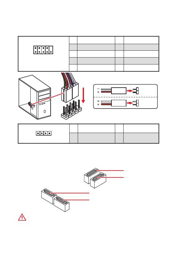
JFP1, JFP2:
, .
1
2 10
9
JFP1
1 HDD LED + 2 Power LED +
3 HDD LED — 4 Power LED —
5 Reset Switch 6 Power Switch
7 Reset Switch 8 Power Switch
9 Reserved 10 No Pin
1
JFP2
1 Speaker — 2 Buzzer +
3 Buzzer — 4 Speaker +
HDD LED
RESET SW
HDD LED
HDD LED —
HDD LED +
POWER LED —
POWER LED +
POWER LED
JFP1
11
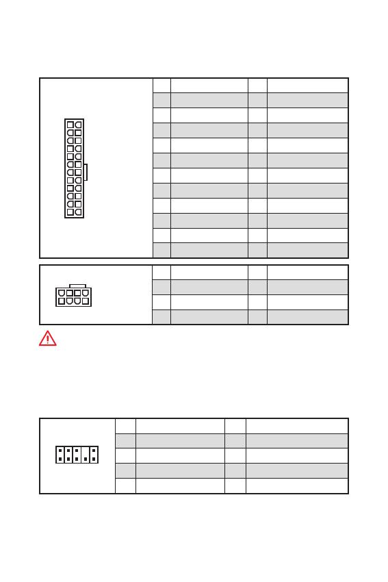
ATX_PWR1, CPU_PWR1:
ATX.
24
131
12
ATX_PWR1
1 +3.3V 13 +3.3V
2 +3.3V 14 -12V
3 Ground 15 Ground
4 +5V 16 PS-ON#
5 Ground 17 Ground
6 +5V 18 Ground
7 Ground 19 Ground
8 PWR OK 20 Res
9 5VSB 21 +5V
10 +12V 22 +5V
11 +12V 23 +5V
12 +3.3V 24 Ground
5
4
1
8
CPU_PWR1
1 Ground 5 +12V
2 Ground 6 +12V
3 Ground 7 +12V
4 Ground 8 +12V
!
.
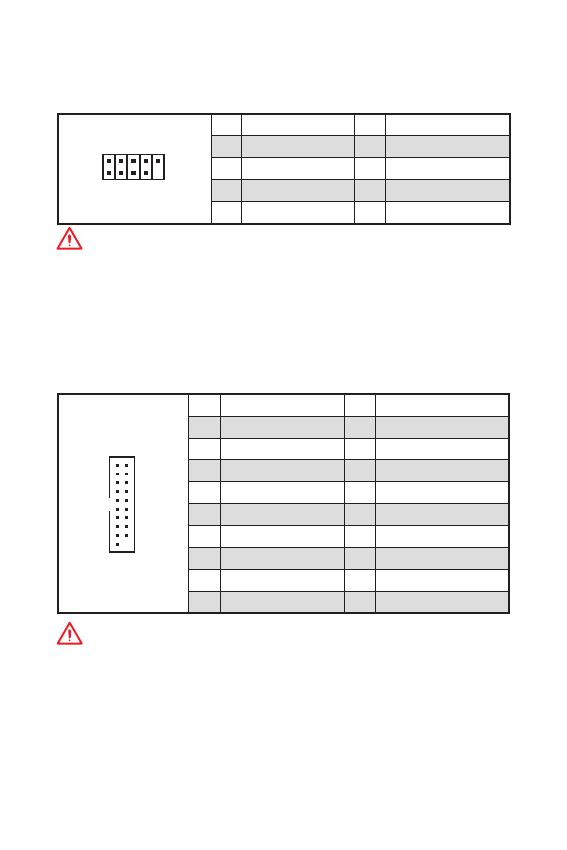
JAUD1:
.
1
2 10
9
1 MIC L 2 Ground
3 MIC R 4 NC
5 Head Phone R 6 MIC Detection
7 SENSE_SEND 8 No Pin
9 Head Phone L 10 Head Phone Detection
12
JUSB2: USB 3.1 Gen1
USB 3.1 Gen1
.
1
10
11
20
1 Power 11 USB2.0+
2 USB3_RX_DN 12 USB2.0-
3 USB3_RX_DP 13 Ground
4 Ground 14 USB3_TX_C_DP
5 USB3_TX_C_DN 15 USB3_TX_C_DN
6 USB3_TX_C_DP 16 Ground
7 Ground 17 USB3_RX_DP
8 USB2.0- 18 USB3_RX_DN
9 USB2.0+ 19 Power
10 NC 20 No Pin
!
, ,
.
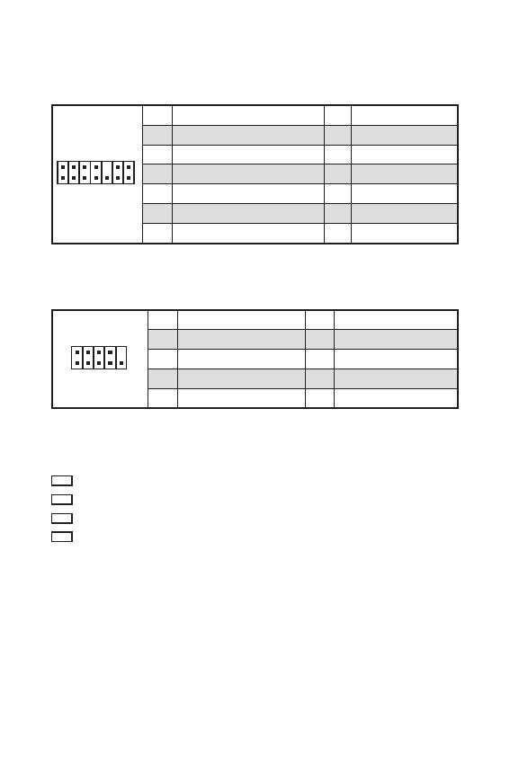
JUSB1: USB 2.0
USB 2.0
.
1
2 10
9
1 VCC 2 VCC
3 USB0- 4 USB1-
5 USB0+ 6 USB1+
7 Ground 8 Ground
9 No Pin 10 NC
!
y
, ,
VCC .
y
, iPad, iPhone iPod USB,
, MSI
®
SUPER CHARGER.
13
JTPM1: TPM
(Trusted Platform
Module). . .
1
2 14
13
1 LPC Clock 2 3V Standby power
3 LPC Reset 4 3.3V Power
5 LPC address & data pin0 6 Serial IRQ
7 LPC address & data pin1 8 5V Power
9 LPC address & data pin2 10 No Pin
11 LPC address & data pin3 12 Ground
13 LPC Frame 14 Ground
JCOM1:
,
.
1
2 10
9
1 DCD 2 SIN
3 SOUT 4 DTR
5 Ground 6 DSR
7 RTS 8 CTS
9 RI 10 No Pin
EZ
.
CPU — .
DRAM — DRAM .
VGA — .
BOOT — .
14
CPU_FAN1, SYS_FAN1:
: PWM (PulseWidth
Modulation) .
PWM
12,
.
,
. ,
3- (Non-PWM)
PWM, .
.
, PWM DC, .
PWM
DC
BIOS > HARDWARE MONITOR
: PWM DC, .
PWM DC
, PWM/ DC.
.
1
CPU_FAN1
1
SYS_FAN1
PWM
1 Ground 2 +12V
3 Sense 4 Speed Control Signal
DC
1 Ground 2 Voltage Control
3 Sense 4 NC
15
JBAT1: CMOS (
BIOS)
CMOS
.
( CMOS ), .
( )
/
BIOS
BIOS
1. .
2. , JBAT1
5-10 .
3. JBAT1.
4. .
JCI1:
.
( )
1. JCI1.
2. .
3. BIOS > SETTINGS > Security > Chassis Intrusion Configuration.
4. Chassis Intrusion to Enabled.
5. F10, ,
Enter, Yes.
6.
.
1. BIOS > SETTINGS > Security > Chassis Intrusion Configuration.
2. Chassis Intrusion Reset.
3. F10, ,
Enter, Yes.
16
BIOS
BIOS
.
BIOS, .
,
.
!
y
, BIOS
.
BIOS .
BIOS,
HELP.
y
.
BIOS
BIOS.
y Delete, Press
DEL key to enter Setup Menu, F11 to enter Boot Menu .
y MSI FAST BOOT. GO2BIOS
.
BIOS.
GO2BIOS
F1:
F2: /
F3:
F4:
F5: Memory-Z
F6:
F7: EZ
F8:
F9:
F10: *
F12: USB — ( FAT /
FAT32 ).
Ctrl+F:
* F10 . Yes
No, .

17
BIOS BIOS
BIOS
BIOS .
:
y BIOS F6
.
y Clear CMOS .
!
, CMOS.
BIOS,
CMOS.
BIOS
BIOS M-FLASH
:
, BIOS MSI,
. BIOS
— USB.
BIOS:
1. — USB, .
2. <Ctrl+F5> POST.
3. Yes
.
4. BIOS BIOS.
5. ,
.
BIOS Live Update 6
:
,
.
BIOS:
1. MSI LIVE UPDATE 6.
2. BIOS Update.
3. Scan.
4. Download,
BIOS.
5. Next In Windows mode.
Next Start BIOS.
6. ,
.

18
Windows
®
10
1. .
2. Windows
®
10 .
3. Restart .
4. F11 POST (Power-On Self Test) ,
.
5. .
6. , Press
any key to boot from CD or DVD…
7. , Windows
®
10.
1. Windows
®
10.
2. MSI
®
Driver Disc
.
3. ,
.
4. Install.
5. .
.
6. OK .
7. .
.
1. MSI
®
Driver Disc
.
2. .
3. Utilities.
4. .
5. Install.
6. .
.
7. OK .
8. .
|
Код: 116681 Извините, товара сейчас нет в наличии
Бесплатная доставка
Извините, товара сейчас нет в наличии Сравнить Новости интернет-магазина «Лаукар»:28.03.2023 22.02.2023 13.02.2023 Дополнительная информация в категории Материнская плата:Таблица Авторизованных сервисных центров по брендам. Описание Инструкция Отзывы (0) В интернет-магазине бытовой техники «Лаукар» Вы можете скачать инструкцию к товару Материнская плата MSI H310M PRO-VD PLUS совершенно бесплатно. Все инструкции, представленные на сайте интернет-магазина бытовой техники «Лаукар», предоставляются производителем товара. Для того чтобы скачать инструкцию, Вам необходимо нажать на ссылку «скачать инструкцию», расположенную ниже, а в случае, если ссылки нет, Скачать инструкцию Смотреть инструкцию
Фирма-производитель оставляет за собой право на внесение изменений в конструкцию, дизайн и комплектацию товара: Материнская плата MSI H310M PRO-VD PLUS. Пожалуйста, сверяйте информацию о товаре с информацией на |


- Manuals
- Brands
- MSI Manuals
- Motherboard
- H310M PRO-VDH PLUS
Manuals and User Guides for MSI H310M PRO-VDH PLUS. We have 1 MSI H310M PRO-VDH PLUS manual available for free PDF download: User Manual
Благодарим Вас за покупку материнской платы
MSI
H310M PRO-VDH
®
пользователя содержит информацию о схеме платы,
компонентах материнской платы, настройке BIOS и
описание программного обеспечения.
Содержание
Безопасное использование продукции ………………………………………… 2
Технические характеристики ………………………………………………………… 3
Задняя панель портов ввода/ вывода ………………………………………….. 6
Таблица состояний индикатора порта LAN ………………………………………..6
Компоненты материнской платы ………………………………………………….. 7
Процессорный сокет ……………………………………………………………………………8
Слоты DIMM ………………………………………………………………………………………….9
PCI_E1~3: Слоты расширения PCIe ………………………………………………………9
JFP1, JFP2: Разъемы передней панели ……………………………………………..10
SATA1~4: Разъемы SATA 6 Гб/с …………………………………………………………….10
ATX_PWR1, CPU_PWR1: Разъемы электропитания ……………………………..11
JAUD1: Разъем аудио передней панели …………………………………………….11
JUSB1: Разъем USB 2.0………………………………………………………………………..12
JUSB2: Разъем USB 3.1 Gen1 ……………………………………………………………….12
JTPM1: Разъем модуля TPM ………………………………………………………………..13
JCOM1: Разъемы последовательного порта ………………………………………13
Индикаторы отладки EZ …………………………………………………………………….13
CPU_FAN1, SYS_FAN1: Разъемы вентиляторов …………………………………..14
JCI1: Разъем датчика открытия корпуса …………………………………………..15
JBAT1: Джампер очистки данных CMOS (Сброс BIOS) ………………………..15
Настройка BIOS ……………………………………………………………………………… 16
Вход в настройки BIOS ……………………………………………………………………….16
Сброс BIOS ………………………………………………………………………………………….17
Обновление BIOS ……………………………………………………………………………….17
Описание программного обеспечения ……………………………………….. 18
Установка Windows
Установка драйверов ………………………………………………………………………..18
Установка утилит ……………………………………………………………………………….18
Downloaded from
PLUS. Данное руководство
10 ……………………………………………………………………….18
®
ManualsNet.com
search engine
Содержание
1
![]()
Thank you for purchasing the MSI® H310M PRO-VDH PLUS motherboard. This User Guide gives information about board layout, component overview, BIOS setup and software installation.
|
Contents |
|
|
Safety Information………………………………………………………………………………. |
2 |
|
Specifications……………………………………………………………………………………… |
3 |
|
Rear I/O Panel ……………………………………………………………………………………. |
6 |
|
LAN Port LED Status Table……………………………………………………………………… |
6 |
|
Overview of Components …………………………………………………………………….. |
7 |
|
CPU Socket …………………………………………………………………………………………… |
8 |
|
DIMM Slots……………………………………………………………………………………………. |
9 |
|
PCI_E1~3: PCIe Expansion Slots ……………………………………………………………… |
9 |
|
JFP1, JFP2: Front Panel Connectors ……………………………………………………… |
10 |
|
SATA1~4: SATA 6Gb/s Connectors………………………………………………………….. |
10 |
|
ATX_PWR1, CPU_PWR1: Power Connectors……………………………………………. |
11 |
|
JAUD1: Front Audio Connector………………………………………………………………. |
11 |
|
JUSB1: USB 2.0 Connector……………………………………………………………………. |
12 |
|
JUSB2: USB 3.1 Gen1 Connector …………………………………………………………… |
12 |
|
JTPM1: TPM Module Connector …………………………………………………………….. |
13 |
|
JCOM1: Serial Port Connector ………………………………………………………………. |
13 |
|
EZ Debug LED ……………………………………………………………………………………… |
13 |
|
CPU_FAN1, SYS_FAN1: Fan Connectors…………………………………………………. |
14 |
|
JCI1: Chassis Intrusion Connector…………………………………………………………. |
15 |
|
JBAT1: Clear CMOS (Reset BIOS) Jumper ………………………………………………. |
15 |
|
BIOS Setup……………………………………………………………………………………….. |
16 |
|
Entering BIOS Setup …………………………………………………………………………….. |
16 |
|
Resetting BIOS…………………………………………………………………………………….. |
17 |
|
Updating BIOS……………………………………………………………………………………… |
17 |
|
Software Description…………………………………………………………………………. |
18 |
|
Installing Windows® 10 …………………………………………………………………………. |
18 |
|
Installing Drivers …………………………………………………………………………………. |
18 |
|
Installing Utilities…………………………………………………………………………………. |
18 |
Contents 1
Safety Information
yThe components included in this package are prone to damage from electrostatic discharge (ESD). Please adhere to the following instructions to ensure successful computer assembly.
yEnsure that all components are securely connected. Loose connections may cause the computer to not recognize a component or fail to start.
yHold the motherboard by the edges to avoid touching sensitive components.
yIt is recommended to wear an electrostatic discharge (ESD) wrist strap when handling the motherboard to prevent electrostatic damage. If an ESD wrist strap is not available, discharge yourself of static electricity by touching another metal object before handling the motherboard.
yStore the motherboard in an electrostatic shielding container or on an anti-static pad whenever the motherboard is not installed.
yBefore turning on the computer, ensure that there are no loose screws or metal components on the motherboard or anywhere within the computer case.
yDo not boot the computer before installation is completed. This could cause permanent damage to the components as well as injury to the user.
yIf you need help during any installation step, please consult a certified computer technician.
yAlways turn off the power supply and unplug the power cord from the power outlet before installing or removing any computer component.
yKeep this user guide for future reference.
yKeep this motherboard away from humidity.
yMake sure that your electrical outlet provides the same voltage as is indicated on the PSU, before connecting the PSU to the electrical outlet.
yPlace the power cord such a way that people can not step on it. Do not place anything over the power cord.
yAll cautions and warnings on the motherboard should be noted.
yIf any of the following situations arises, get the motherboard checked by service personnel:
Liquid has penetrated into the computer.
The motherboard has been exposed to moisture.
The motherboard does not work well or you can not get it work according to user guide.
The motherboard has been dropped and damaged.
The motherboard has obvious sign of breakage.
yDo not leave this motherboard in an environment above 60°C (140°F), it may damage the motherboard.
2 Safety Information

Specifications
|
CPU |
Supports 8th Generation Intel® Core™ Processors, Pentium® |
|
|
Gold and Celeron® Processors for Socket LGA1151 |
||
|
Intel® H310 Chipset* |
||
|
Chipset |
* This chipset is ME11 firmware based and doesn’t feature |
|
|
SDA3.0. |
||
|
y 2x DDR4 memory slots, support up to 32GB* |
||
|
y Supports DDR4 2666/ 2400/ 2133 MHz (by JEDEC)** |
||
|
y Supports DDR4 2666/ 2400/ 2133 MHz (by XMP OC)** |
||
|
Memory |
y Supports Dual-Channel mode |
|
|
y Supports non-ECC, un-buffered memory |
||
|
y Supports Intel® Extreme Memory Profile (XMP) |
||
|
* Please refer www.msi.com for more information on |
||
|
compatible memory. |
||
|
** 2666 MHz for I7 and I5 processors only. |
||
|
Expansion Slots |
y 1x PCIe 3.0 x16 slot |
|
|
y 2x PCIe 2.0 x1 slots |
||
|
y 1x VGA port, supports a maximum resolution of |
||
|
2048×1536@50Hz, 2048×1280@60Hz, 1920×1200@60Hz |
||
|
Onboard |
y 1x DVI-D port, supports a maximum resolution of |
|
|
1920×1200@60Hz |
||
|
Graphics |
y 1x HDMI™ port, supports a maximum resolution of |
|
|
4096×2160@30Hz |
||
|
* Supports up to 2 displays simultaneously. |
||
|
Intel® H310 Chipset |
||
|
Storage |
y 4x SATA 6Gb/s ports |
|
|
Supports Intel® Rapid Storage Technology |
||
|
Intel® H310 Chipset |
||
|
y 4x USB 3.1 Gen1 (SuperSpeed USB) ports (2 Type-A ports |
||
|
USB |
on the back panel, 2 ports available through the internal USB |
|
|
connector) |
||
|
y 6x USB 2.0 (High-speed USB) ports (4 ports on the back |
||
|
panel, 2 ports available through the internal USB connector) |
||
|
Audio |
y Realtek® ALC887 Codec |
|
|
y 7.1-Channel High Definition Audio |
||
|
LAN |
1x Realtek RTL8111H Gigabit LAN controller |
|
|
Continued on next page |
Specifications 3

|
Continued from previous page |
||
|
y 1x PS/2 keyboard/Mouse combo port |
||
|
y 4x USB 2.0 ports |
||
|
y 1x DVI-D port |
||
|
Back Panel |
y 1x VGA port |
|
|
Connectors |
y 1x HDMI™ port |
|
|
y 2x USB 3.1 Gen1 Type-A ports |
||
|
y 1x LAN (RJ45) port |
||
|
y 3x audio jacks |
||
|
y 1x 24-pin ATX main power connector |
||
|
y 1x 8-pin ATX 12V power connector |
||
|
y 4x SATA 6Gb/s connectors |
||
|
y 1x USB 3.1 Gen1 connector (supports additional 2 USB 3.1 |
||
|
Gen1 ports) |
||
|
y 1x USB 2.0 connector (supports additional 2 USB 2.0 ports) |
||
|
Internal |
y 1x Clear CMOS jumper |
|
|
y 2x Front panel connectors |
||
|
Connectors |
||
|
y 1x Serial port connector |
||
|
y 1x TPM module connector |
||
|
y 1x Chassis Intrusion connector |
||
|
y 1x Front panel audio connector |
||
|
y 1x 4-pin CPU fan connector |
||
|
y 1x 4-pin system fan connector |
||
|
I/O Controller |
NUVOTON NCT5567 Controller Chip |
|
|
Hardware |
y CPU/System temperature detection |
|
|
y CPU/System fan speed detection |
||
|
Monitor |
||
|
y CPU/System fan speed control |
||
|
Form Factor |
y m-ATX Form Factor |
|
|
y 8.9 in. x 7.3 in. (22.6 cm x 18.5 cm) |
||
|
y 1x 128 Mb flash |
||
|
BIOS Features |
y UEFI AMI BIOS |
|
|
y ACPI 6.1, SM BIOS 2.8 |
||
|
y Multi-language |
||
|
Continued on next page |
4 Specifications
Continued from previous page
|
y Drivers |
||
|
y APP MANAGER |
||
|
y SUPER CHARGER |
||
|
y COMMAND CENTER |
||
|
y LIVE UPDATE 6 |
||
|
y SMART TOOL |
||
|
Software |
y RAMDISK |
|
|
y FAST BOOST |
||
|
y X-BOOST |
||
|
y DPC LATENCY TUNER |
||
|
y CPU-Z MSI GAMING |
||
|
y Intel Extreme Tuning Utility |
||
|
y Google Chrome™ ,Google Toolbar, Google Drive |
||
|
y Norton™ Internet Security Solution |
||
Specifications 5
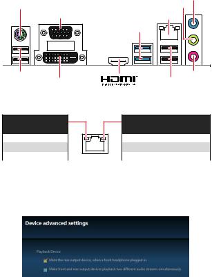
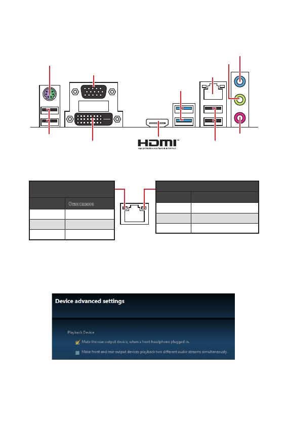
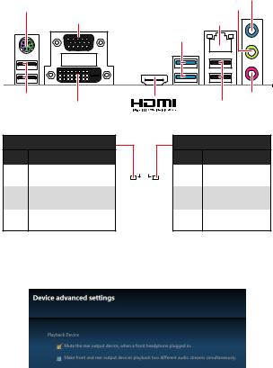
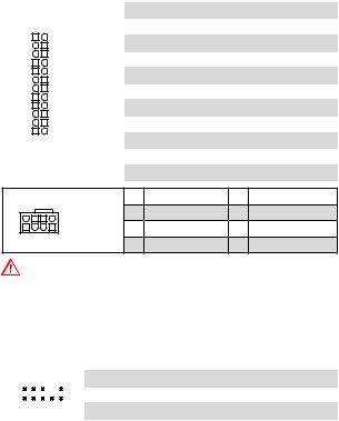
Rear I/O Panel
|
Line-in |
|
|
PS/2 Keyboard/ Mouse |
Line-out |
|
VGA |
LAN |
|
USB 3.1 Gen1 |
|
|
USB 2.0 |
Mic in |
|
DVI-D |
USB 2.0 |
LAN Port LED Status Table
Link/ Activity LED
|
Status |
Description |
|
Off |
No link |
|
Yellow |
Linked |
|
Blinking |
Data activity |
Speed LED
|
Status |
Description |
|
Off |
10 Mbps connection |
|
Green |
100 Mbps connection |
|
Orange |
1 Gbps connection |
Audio 7.1-channel Configuration
To configure 7.1-channel audio, you have to connect front audio I/O module to JAUD1 connector and follow the below steps.
1.Click on the Realtek HD Audio Manager > Advanced Settings to open the dialog below.
2.Select Mute the rear output device, when a front headphone plugged in.
3.Plug your speakers to audio jacks on rear and front I/O panel. When you plug into a device at an audio jack, a dialogue window will pop up asking you which device is current connected.
6 Rear I/O Panel

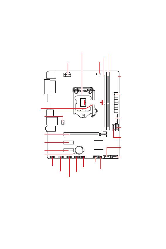
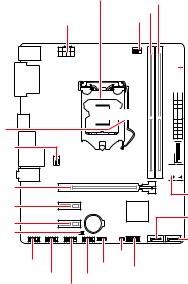
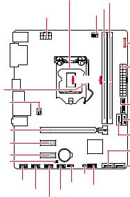
Overview of Components
Distance from the center of the CPU to the nearest DIMM slot.
SYS_FAN1
PCI_E1
PCI_E2
PCI_E3
JBAT1
CPU_PWR1 CPU_FAN1

 EZ Debug LED


 ATX_PWR1

 51.27 mm


 JUSB2
JUSB2


 SATA1
SATA1
|
SATA2 |
|||
|
BAT1 |
SATA4 |
||
|
SATA3 |
|||
|
JAUD1 |
JCI1 |
||
|
JFP2 |
JTPM1 |
||
|
JCOM1 |
JFP1 |
||
JUSB1
Overview of Components 7
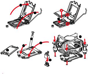
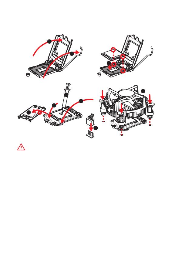
CPU Socket
Please install the CPU into the CPU socket as shown below.
2
1
3


 8 7
8 7 


5
 4 6
4 6


9
 Important
yAlways unplug the power cord from the power outlet before installing or removing the CPU.
yPlease retain the CPU protective cap after installing the processor. MSI will deal with Return Merchandise Authorization (RMA) requests if only the motherboard comes with the protective cap on the CPU socket.
yWhen installing a CPU, always remember to install a CPU heatsink. A CPU heatsink is necessary to prevent overheating and maintain system stability.
yConfirm that the CPU heatsink has formed a tight seal with the CPU before booting your system.
yOverheating can seriously damage the CPU and motherboard. Always make sure the cooling fans work properly to protect the CPU from overheating. Be sure to apply an even layer of thermal paste (or thermal tape) between the CPU and the heatsink to enhance heat dissipation.
yWhenever the CPU is not installed, always protect the CPU socket pins by covering the socket with the plastic cap.
yIf you purchased a separate CPU and heatsink/ cooler, Please refer to the documentation in the heatsink/ cooler package for more details about installation.
8 Overview of Components
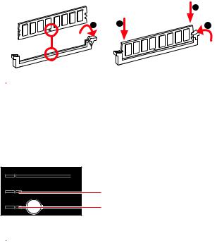
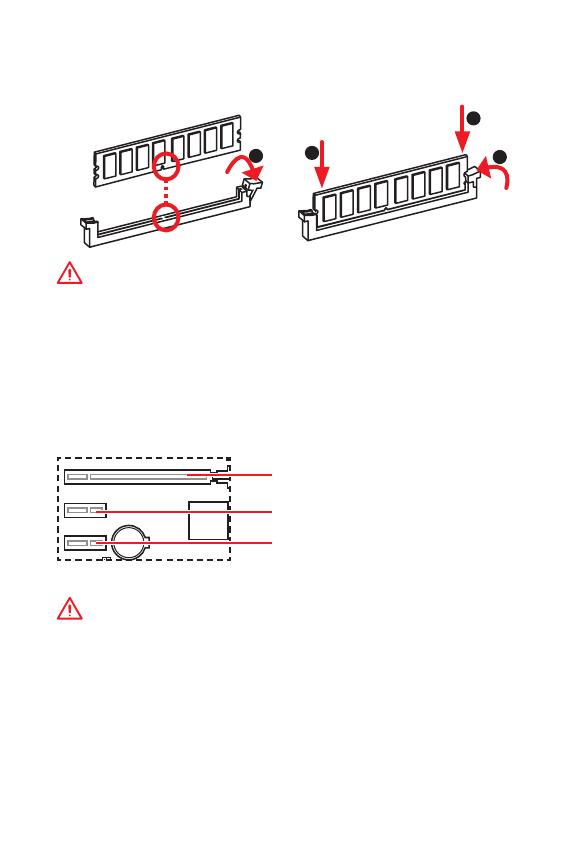
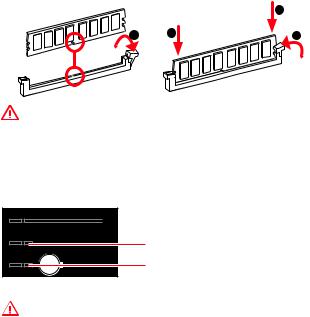
DIMM Slots
Please install the memory module into the DIMM slot as shown below.
2
 Important
y Due to chipset resource usage, the available capacity of memory will be a little less than the amount of installed.
y Please note that the maximum capacity of addressable memory is 4GB or less for 32-bit Windows OS due to the memory address limitation. Therefore, we
recommended that you to install 64-bit Windows OS if you want to install more than 4GB memory on the motherboard.
PCI_E1~3: PCIe Expansion Slots
BAT1
 PCI_E1: PCIe 3.0 x16 (CPU lanes)
PCI_E2: PCIe 2.0 x1 slot (PCH lanes)
PCI_E3: PCIe 2.0 x1 slot (PCH lanes)
 Important
yIf you install a large and heavy graphics card, you need to use a tool such as MSI Gaming Series Graphics Card Bolster to support its weight to prevent deformation of the slot.
yWhen adding or removing expansion cards, always turn off the power supply and unplug the power supply power cable from the power outlet. Read the expansion card’s documentation to check for any necessary additional hardware or software changes.
Overview of Components 9
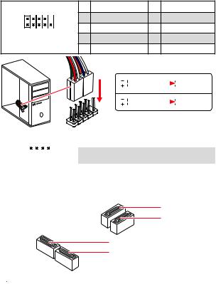
JFP1, JFP2: Front Panel Connectors
These connectors connect to the switches and LEDs on the front panel.
|
2 |
10 |
1 |
HDD LED + |
2 |
Power LED + |
|
|
3 |
HDD LED — |
4 |
Power LED — |
|||
|
1 |
9 |
5 |
Reset Switch |
6 |
Power Switch |
|
|
7 |
Reset Switch |
8 |
Power Switch |
|||
|
JFP1 |
||||||
|
9 |
Reserved |
10 |
No Pin |
HDD
 LEDSWRESET
JFP1
|
HDD LED |
HDD LED — |
||||||
|
HDD LED + |
|||||||
|
POWER LED — |
|||||||
|
POWER LED |
POWER LED + |
||||||
|
1 |
1 |
Speaker — |
2 |
Buzzer + |
|||||
|
3 |
Buzzer — |
4 |
Speaker + |
||||||
|
JFP2 |
|||||||||
SATA1~4: SATA 6Gb/s Connectors
These connectors are SATA 6Gb/s interface ports. Each connector can connect to one SATA device.
SATA2 SATA1
SATA4
SATA3
 Important
yPlease do not fold the SATA cable at a 90-degree angle. Data loss may result during transmission otherwise.
ySATA cables have identical plugs on either sides of the cable. However, it is recommended that the flat connector be connected to the motherboard for space saving purposes.
10 Overview of Components
![]()
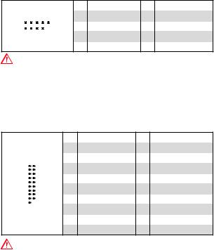
ATX_PWR1, CPU_PWR1: Power Connectors
These connectors allow you to connect an ATX power supply.
|
1 |
+3.3V |
13 |
+3.3V |
|||||
|
2 |
+3.3V |
14 |
-12V |
|||||
|
12 |
24 |
3 |
Ground |
15 |
Ground |
|||
|
4 |
+5V |
16 |
PS-ON# |
|||||
|
5 |
Ground |
17 |
Ground |
|||||
|
ATX_PWR1 |
6 |
+5V |
18 |
Ground |
||||
|
7 |
Ground |
19 |
Ground |
|||||
|
8 |
PWR OK |
20 |
Res |
|||||
|
1 |
13 |
9 |
5VSB |
21 |
+5V |
|||
|
10 |
+12V |
22 |
+5V |
|||||
|
11 |
+12V |
23 |
+5V |
|||||
|
12 |
+3.3V |
24 |
Ground |
|
8 |
5 |
1 |
Ground |
5 |
+12V |
|
|
CPU_PWR1 |
2 |
Ground |
6 |
+12V |
||
|
3 |
Ground |
7 |
+12V |
|||
|
4 |
1 |
|||||
|
4 |
Ground |
8 |
+12V |
|||
 Important
Make sure that all the power cables are securely connected to a proper ATX power supply to ensure stable operation of the motherboard.
JAUD1: Front Audio Connector
This connector allow you to connect audio jacks on the front panel.
|
1 |
MIC L |
2 |
Ground |
|||||||
|
2 |
10 |
3 |
MIC R |
4 |
NC |
|||||
|
5 |
Head Phone R |
6 |
MIC Detection |
|||||||
|
1 |
9 |
7 |
SENSE_SEND |
8 |
No Pin |
|||||
|
9 |
Head Phone L |
10 |
Head Phone Detection |
Overview of Components 11
JUSB1: USB 2.0 Connector
This connector allows you to connect USB 2.0 ports on the front panel.
|
1 |
VCC |
2 |
VCC |
|||||||
|
2 |
10 |
3 |
USB0- |
4 |
USB1- |
|||||
|
5 |
USB0+ |
6 |
USB1+ |
|||||||
|
1 |
9 |
7 |
Ground |
8 |
Ground |
|||||
|
9 |
No Pin |
10 |
NC |
 Important
yNote that the VCC and Ground pins must be connected correctly to avoid possible damage.
yIn order to recharge your iPad,iPhone and iPod through USB ports, please install MSI® SUPER CHARGER utility.
JUSB2: USB 3.1 Gen1 Connector
This connector allows you to connect USB 3.1 Gen1 ports on the front panel.
|
1 |
Power |
11 |
USB2.0+ |
|
2 |
USB3_RX_DN |
12 |
USB2.0- |
|
3 |
USB3_RX_DP |
13 |
Ground |
|
4 |
Ground |
14 |
USB3_TX_C_DP |
|
5 |
USB3_TX_C_DN |
15 |
USB3_TX_C_DN |
|
6 |
USB3_TX_C_DP |
16 |
Ground |
|
7 |
Ground |
17 |
USB3_RX_DP |
|
8 |
USB2.0- |
18 |
USB3_RX_DN |
|
9 |
USB2.0+ |
19 |
Power |
|
10 |
NC |
20 |
No Pin |
 Important
Note that the Power and Ground pins must be connected correctly to avoid possible damage.
12 Overview of Components

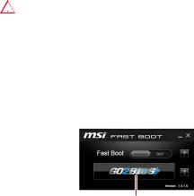
JTPM1: TPM Module Connector
This connector is for TPM (Trusted Platform Module). Please refer to the TPM security platform manual for more details and usages.
|
1 |
LPC Clock |
2 |
3V Standby power |
|||||||||
|
3 |
LPC Reset |
4 |
3.3V Power |
|||||||||
|
2 |
14 |
5 |
LPC address & data pin0 |
6 |
Serial IRQ |
|||||||
|
7 |
LPC address & data pin1 |
8 |
5V Power |
|||||||||
|
1 |
13 |
9 |
LPC address & data pin2 |
10 |
No Pin |
|||||||
|
11 |
LPC address & data pin3 |
12 |
Ground |
|||||||||
|
13 |
LPC Frame |
14 |
Ground |
JCOM1: Serial Port Connector
This connector allows you to connect the optional serial port with bracket.
|
1 |
DCD |
2 |
SIN |
|||||||
|
2 |
10 |
3 |
SOUT |
4 |
DTR |
|||||
|
5 |
Ground |
6 |
DSR |
|||||||
|
1 |
9 |
7 |
RTS |
8 |
CTS |
|||||
|
9 |
RI |
10 |
No Pin |
EZ Debug LED
These LEDs indicate the status of the motherboard.

 CPU — indicates CPU is not detected or fail.

 DRAM — indicates DRAM is not detected or fail.

 VGA — indicates GPU is not detected or fail.

 BOOT — indicates booting device is not detected or fail.
Overview of Components 13
Default PWM Mode fan connectors
Default DC Mode fan connectors
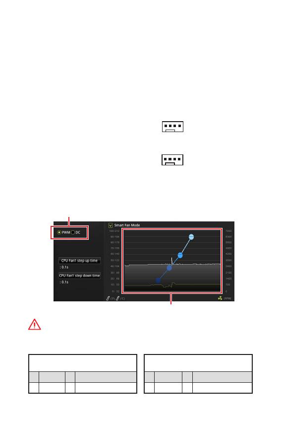
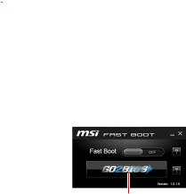
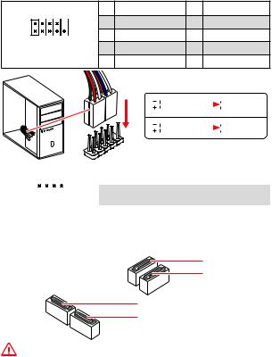
CPU_FAN1, SYS_FAN1: Fan Connectors
Fan connectors can be classified as PWM (Pulse Width Modulation) Mode or DC Mode. PWM Mode fan connectors provide constant 12V output and adjust fan speed with speed control signal. DC Mode fan connectors control fan speed by changing voltage. When you plug a 3-pin (Non-PWM) fan to a fan connector in PWM mode, the fan speed will always maintain at 100%, which might create a lot of noise. You can follow the instruction below to adjust the fan connector to PWM or DC Mode.
1
CPU_FAN1
1
SYS_FAN1
Switching fan mode and adjusting fan speed
You can switch between PWM mode and DC mode and adjust fan speed in BIOS > HARDWARE MONITOR.
Select PWM mode or DC mode
There are gradient points of the fan speed that allow you to adjust fan speed in relation to CPU temperature.
 Important
Make sure fans are working properly after switching the PWM/ DC mode.
Pin definition of fan connectors
PWM Mode pin definition
|
1 |
Ground |
2 |
+12V |
|
|
3 |
Sense |
4 |
Speed Control |
|
|
Signal |
||||
DC Mode pin definition
|
1 |
Ground |
2 |
Voltage |
|
|
Control |
||||
|
3 |
Sense |
4 |
NC |
14 Overview of Components

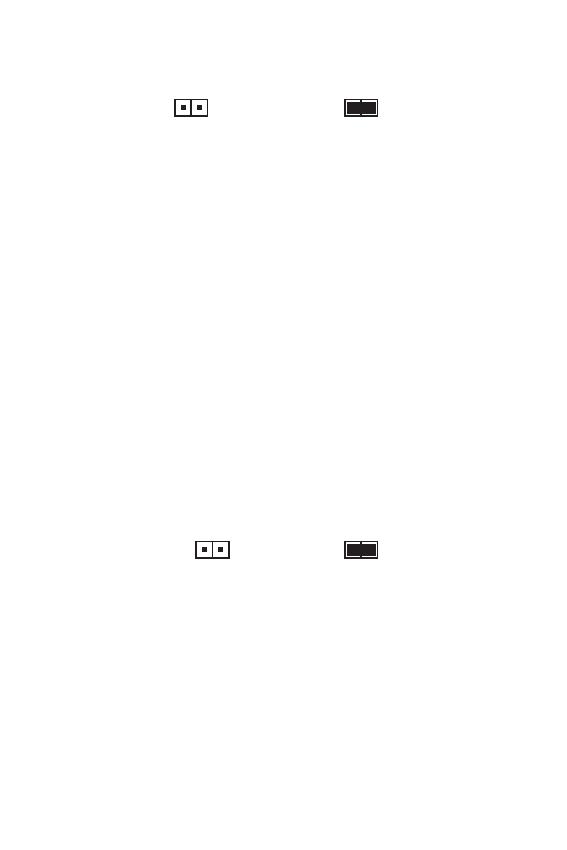
JCI1: Chassis Intrusion Connector
This connector allows you to connect the chassis intrusion switch cable.
|
Normal |
Trigger the chassis |
|||
|
(default) |
intrusion event |
|||
Using chassis intrusion detector
1.Connect the JCI1 connector to the chassis intrusion switch/ sensor on the chassis.
2.Close the chassis cover.
3.Go to BIOS > SETTINGS > Security > Chassis Intrusion Configuration.
4.Set Chassis Intrusion to Enabled.
5.Press F10 to save and exit and then press the Enter key to select Yes.
6.Once the chassis cover is opened again, a warning message will be displayed on screen when the computer is turned on.
Resetting the chassis intrusion warning
1.Go to BIOS > SETTINGS > Security > Chassis Intrusion Configuration.
2.Set Chassis Intrusion to Reset.
3.Press F10 to save and exit and then press the Enter key to select Yes.
JBAT1: Clear CMOS (Reset BIOS) Jumper
There is CMOS memory onboard that is external powered from a battery located on the motherboard to save system configuration data. If you want to clear the system configuration, set the jumper to clear the CMOS memory.
|
Keep Data |
Clear CMOS/ Reset |
|||
|
(default) |
BIOS |
Resetting BIOS to default values
1.Power off the computer and unplug the power cord
2.Use a jumper cap to short JBAT1 for about 5-10 seconds.
3.Remove the jumper cap from JBAT1.
4.Plug the power cord and power on the computer.
Overview of Components 15
BIOS Setup
The default settings offer the optimal performance for system stability in normal conditions. You should always keep the default settings to avoid possible system damage or failure booting unless you are familiar with BIOS.
 Important
yBIOS items are continuously update for better system performance. Therefore, the description may be slightly different from the latest BIOS and should be for reference only. You could also refer to the HELP information panel for BIOS item description.
yThe pictures in this chapter are for reference only and may vary from the product you purchased.
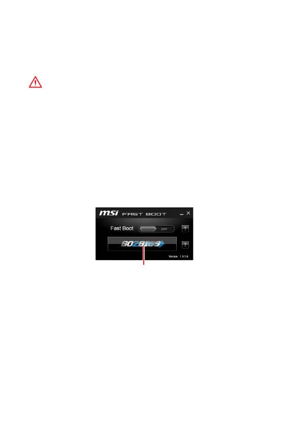
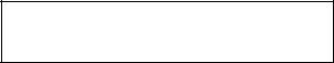
Entering BIOS Setup
Please refer the following methods to enter BIOS setup.
yPress Delete key, when the Press DEL key to enter Setup Menu, F11 to enter Boot Menu message appears on the screen during the boot process.
yUse MSI FAST BOOT application. Click on GO2BIOS button and choose OK. The system will reboot and enter BIOS setup directly.
Click on GO2BIOS
Function key
F1: General Help
F2: Add/ Remove a favorite item
F3: Enter Favorites menu
F4: Enter CPU Specifications menu
F5: Enter Memory-Z menu
F6: Load optimized defaults
F7: Switch between Advanced mode and EZ mode
F8: Load Overclocking Profile
F9: Save Overclocking Profile
F10: Save Change and Reset*
F12: Take a screenshot and save it to USB flash drive (FAT/ FAT32 format only). Ctrl+F: Enter Search page
* When you press F10, a confirmation window appears and it provides the modification information. Select between Yes or No to confirm your choice.
16 BIOS Setup

Resetting BIOS
You might need to restore the default BIOS setting to solve certain problems. There are several ways to reset BIOS:
yGo to BIOS and press F6 to load optimized defaults.
yShort the Clear CMOS jumper on the motherboard.
 Important
Be sure the computer is off before clearing CMOS data. Please refer to the Clear CMOS jumper section for resetting BIOS.
Updating BIOS
Updating BIOS with M-FLASH
Before updating:
Please download the latest BIOS file that matches your motherboard model from MSI website. And then save the BIOS file into the USB flash drive.
Updating BIOS:
1.Insert the USB flash drive that contains the update file into the computer.
2.Press <Ctrl+F5> key during POST.
3.Click on Yes to reboot the system and enter the flash mode.
4.Select a BIOS file to perform the BIOS update process.
5.After the flashing process is 100% completed, the system will reboot automatically.
Updating the BIOS with Live Update 6
Before updating:
Make sure the LAN driver is already installed and the Internet connection is set properly.
Updating BIOS:
1.Install and launch MSI LIVE UPDATE 6.
2.Select BIOS Update.
3.Click on Scan button.
4.Click on Download icon to download and install the latest BIOS file.
5.Click Next and choose In Windows mode. And then click Next and Start to start updating BIOS.
6.After the flashing process is 100% completed, the system will restart automatically.
BIOS Setup 17
Software Description
Installing Windows® 10
1.Power on the computer.
2.Insert the Windows® 10 disc into your optical drive.
3.Press the Restart button on the computer case.
4.Press F11 key during the computer POST (Power-On Self Test) to get into Boot Menu.
5.Select your optical drive from the Boot Menu.
6.Press any key when screen shows Press any key to boot from CD or DVD…
message.
7.Follow the instructions on the screen to install Windows® 10.
Installing Drivers
1.Start up your computer in Windows® 10.
2.Insert MSI® Driver Disc into your optical drive.
3.The installer will automatically appear and it will find and list all necessary drivers.
4.Click Install button.
5.The software installation will then be in progress, after it has finished it will prompt you to restart.
6.Click OK button to finish.
7.Restart your computer.
Installing Utilities
Before you install utilities, you must complete drivers installation.
1.Insert MSI® Driver Disc into your optical drive.
2.The installer will automatically appear.
3.Click Utilities tab.
4.Select the utilities you want to install.
5.Click Install button.
6.The utilities installation will then be in progress, after it has finished it will prompt you to restart.
7.Click OK button to finish.
8.Restart your computer.
18 Software Description
MSI® H310M PRO-VDH PLUS. , , BIOS.
|
…………………………………………………………………………………………….. |
2 |
||
|
……………………………………………………………………………………………………. |
3 |
||
|
I/O ……………………………………………………………………………………….. |
6 |
||
|
LAN |
LED …………………………………………………………………………… |
6 |
|
|
………………………………………………………………………………………….. |
7 |
||
|
CPU |
……………………………………………………………………………………………….. |
8 |
|
|
DIMM …………………………………………………………………………………………….. |
9 |
||
|
PCI_E1~3: PCIe ………………………………………………………………………… |
9 |
||
|
JFP1, JFP2: …………………………………………………………………. |
10 |
||
|
SATA1~4: SATA 6Gb/s …………………………………………………………………. |
10 |
||
|
ATX_PWR1, CPU_PWR1: ………………………………………………………. |
11 |
||
|
JAUD1: …………………………………………………………………….. |
11 |
||
|
JUSB1: USB 2.0 …………………………………………………………………………. |
12 |
||
|
JUSB2: USB 3.1 Gen1 …………………………………………………………………. |
12 |
||
|
JTPM1: TPM ……………………………………………………………………….. |
13 |
||
|
JCOM1: …………………………………………………………………….. |
13 |
||
|
EZ LED ……………………………………………………………………………………… |
13 |
||
|
CPU_FAN1, SYS_FAN1: …………………………………………………………… |
14 |
||
|
JCI1: |
……………………………………………………………………………. |
15 |
|
|
JBAT1: CMOS (Reset BIOS) …………………………………………………… |
15 |
||
|
BIOS ………………………………………………………………………………………….. |
16 |
||
|
BIOS |
…………………………………………………………………………………………….. |
16 |
|
|
BIOS |
…………………………………………………………………………………………….. |
17 |
|
|
BIOS |
………………………………………………………………………………………. |
17 |
|
|
………………………………………………………………………………….. |
18 |
||
|
Windows® 10 …………………………………………………………….. |
18 |
||
|
…………………………………………………………………………………. |
18 |
||
|
…………………………………………………………………………………. |
18 |
1
y (ESD).
y . ,.
y .
y ESD. ESD ,.
y .
y .
y . ,.
y .
y .
y . y .
y PSU PSU.
y . . y .
y , ..
.
..
.
y 60°C (140°F) . .
2
![]()
|
CPU |
® |
™ , |
|||||||
|
LGA1151 |
8 |
® |
® |
||||||
|
Intel® H310 * |
, SDA 3.0 |
||||||||
|
* ME11 |
|||||||||
|
. |
|||||||||
|
y DDR4 2 , 32GB* |
|||||||||
|
y DDR4 2666/ 2400/ 2133 MHz (by JEDEC)** |
|||||||||
|
y DDR4 2666/ 2400/ 2133 MHz(by XMP OC)** |
|||||||||
|
y |
|||||||||
|
y non-ECC, un-buffered |
|||||||||
|
y Intel® Extreme Memory Profile (XMP) |
|||||||||
|
* http://www.msi.com |
|||||||||
|
**I7 I5 |
2666 MHz . |
||||||||
|
y PCIe 3.0 x16 1 |
|||||||||
|
y |
2 |
||||||||
|
PCIe 2.0 x1 |
|||||||||
|
y VGA 1 , 2048×1536@50Hz, 2048×1280@60Hz, |
|||||||||
|
1920×1200@60Hz |
|||||||||
|
y DVI-D |
1 , |
1920×1200@60Hz |
|||||||
|
y HDMI™ 1 , 4096×2160@30Hz |
|||||||||
|
* 2 |
|||||||||
|
Intel® H310 |
|||||||||
|
y SATA 6Gb/s 4 |
|||||||||
|
Intel® Rapid Storage |
|||||||||
|
Intel® H310 |
|||||||||
|
USB |
y USB 3.1 Gen1 ( USB) 4 ( A 2 |
||||||||
|
, USB 2 ) |
|||||||||
|
y USB 2.0 ( USB) 6 ( 4 , USB |
|||||||||
|
2 ) |
|||||||||
|
y Realtek® ALC887 |
|||||||||
|
y |
|||||||||
|
7.1- HD |
|||||||||
|
LAN |
Realtek RTL8111H Gigabit LAN 1 |
||||||||
3

|
y PS/2 / 1 |
|||
|
y USB 2.0 4 |
|||
|
y DVI-D 1 |
|||
|
y VGA 1 |
|||
|
y HDMI™ 1 |
|||
|
y USB 3.1 Gen1 A 2 |
|||
|
y LAN (RJ45) |
1 |
||
|
y 3 |
|||
|
y 24 ATX 1 |
|||
|
y 8 ATX 12V |
1 |
||
|
y SATA 6Gb/s |
4 |
||
|
y USB 3.1 Gen1 1 ( USB 3.1 Gen1 2 ) |
|||
|
y USB 2.0 1 ( USB 2.0 2 ) |
|||
|
y CMOS 1 |
|||
|
y |
2 |
||
|
y 1 |
|||
|
y TPM |
1 |
||
|
y |
1 |
||
|
y 1 |
|||
|
y 4 CPU 1 |
|||
|
y 4 1 |
|||
|
I/O |
NUVOTON NCT5567 |
yCPU/y CPU/
yCPU/
|
y m-ATX |
|
|
y 8.9 in. x 7.3 in. (22.6 cm x 18.5 cm) |
|
|
y 128 Mb 1 |
|
|
BIOS |
y UEFI AMI BIOS |
|
y ACPI 6.1, SM BIOS 2.8 |
|
|
y |
|
4
|
y |
||
|
y |
||
|
y |
||
|
y |
||
|
y 6 |
||
|
y |
||
|
y |
||
|
y |
||
|
y X- |
||
|
y DPC |
||
|
y CPU-Z MSI |
||
|
y |
||
|
y : , |
, |
|
|
y ™ |
5
I/O
|
VGA |
LAN |
||
|
USB 3.1 Gen1 |
|||
|
USB 2.0 |
Mic |
||
|
DVI-D |
USB 2.0 |
||
|
LAN LED |
|||
|
/ LED |
LED |
||
|
LAN |
10 Mbps |
||||||||||
|
. |
. |
||||||||||
|
LAN |
100 Mbps |
||||||||||
|
. |
. |
||||||||||
|
LAN |
1 Gbps |
||||||||||
|
. |
. |
7.1-
7.1 I/O JAUD1 ..
1.Realtek HD Audio Manager(Realtek HD ) > Advanced Settings() .
2.Mute the rear output device, when a front headphone plugged in() .
3.I/O ..
6 I/O
CPU DIMM
SYS_FAN1
PCI_E1
PCI_E2
PCI_E3
JBAT1
|
CPU |
DIMMB1 |
|
|
DIMMA1 |
||
|
CPU_PWR1 |
CPU_FAN1 |
 EZ LED


 ATX_PWR1

 51.27 mm


 JUSB2
JUSB2


 SATA1
SATA1
|
SATA2 |
|||
|
BAT1 |
SATA4 |
||
|
SATA3 |
|||
|
JCI1 |
|||
|
JAUD1 |
JFP2 |
JTPM1 |
|
|
JCOM1 |
JFP1 |
||
JUSB1
7

CPU
CPU CPU .
2
1
3


 8 7
8 7 


5
 4 6
4 6


9

yCPU .
y, CPU . CPUMSI (RMA) .
yCPU , CPU . CPU.
yCPU .
yCPU CPU. CPU( ) .
yCPU , CPU.
yCPU / , /.
8
DIMM
DIMM .
2
y.
y4GB 32- (Windows OS). 4GB 64Windows OS .
PCI_E1~3: PCIe
BAT1
 PCI_E1: PCIe 3.0 x16 (CPU )
PCI_E2: PCIe 2.0 x1 (PCH )
PCI_E3: PCIe 2.0 x1 (PCH )
y,MSI Gaming Series Graphics Card Bolster.
y..
9
JFP1, JFP2:
LED .
|
2 |
10 |
1 |
HDD LED + |
2 |
Power LED + |
|
|
3 |
HDD LED — |
4 |
Power LED — |
|||
|
1 |
9 |
5 |
Reset Switch |
6 |
Power Switch |
|
|
7 |
Reset Switch |
8 |
Power Switch |
|||
|
JFP1 |
||||||
|
9 |
Reserved |
10 |
No Pin |
HDD
 LEDSWRESET
JFP1
|
HDD LED |
HDD LED — |
||||||
|
HDD LED + |
|||||||
|
POWER LED — |
|||||||
|
POWER LED |
POWER LED + |
||||||
|
1 |
1 |
Speaker — |
2 |
Buzzer + |
|||||
|
3 |
Buzzer — |
4 |
Speaker + |
||||||
|
JFP2 |
|||||||||
SATA1~4: SATA 6Gb/s
SATA 6Gb/s . SATA.
SATA2 SATA1
SATA4
SATA3
ySATA 90 . , .
ySATA .
10
ATX_PWR1, CPU_PWR1:
ATX .
|
1 |
+3.3V |
13 |
+3.3V |
|||||
|
2 |
+3.3V |
14 |
-12V |
|||||
|
12 |
24 |
3 |
Ground |
15 |
Ground |
|||
|
4 |
+5V |
16 |
PS-ON# |
|||||
|
5 |
Ground |
17 |
Ground |
|||||
|
ATX_PWR1 |
6 |
+5V |
18 |
Ground |
||||
|
7 |
Ground |
19 |
Ground |
|||||
|
8 |
PWR OK |
20 |
Res |
|||||
|
1 |
13 |
9 |
5VSB |
21 |
+5V |
|||
|
10 |
+12V |
22 |
+5V |
|||||
|
11 |
+12V |
23 |
+5V |
|||||
|
12 |
+3.3V |
24 |
Ground |
|
8 |
5 |
1 |
Ground |
5 |
+12V |
|
|
CPU_PWR1 |
2 |
Ground |
6 |
+12V |
||
|
3 |
Ground |
7 |
+12V |
|||
|
4 |
1 |
|||||
|
4 |
Ground |
8 |
+12V |
|||
|
ATX |
||||||
|
. |
JAUD1:
.
|
1 |
MIC L |
2 |
Ground |
|||||||
|
2 |
10 |
3 |
MIC R |
4 |
NC |
|||||
|
5 |
Head Phone R |
6 |
MIC Detection |
|||||||
|
1 |
9 |
7 |
SENSE_SEND |
8 |
No Pin |
|||||
|
9 |
Head Phone L |
10 |
Head Phone Detection |
11
JUSB1: USB 2.0
USB 2.0 .
|
1 |
VCC |
2 |
VCC |
||||||
|
2 |
10 |
3 |
USB0- |
4 |
USB1- |
||||
|
5 |
USB0+ |
6 |
USB1+ |
||||||
|
1 |
9 |
7 |
Ground |
8 |
Ground |
||||
|
9 |
No Pin |
10 |
NC |
yVCC .
yUSB iPad,iPhone iPod MSI® SUPER CHARGER
.
JUSB2: USB 3.1 Gen1
USB 3.1 Gen1 .
|
1 |
Power |
11 |
USB2.0+ |
||||
|
2 |
USB3_RX_DN |
12 |
USB2.0- |
||||
|
10 |
11 |
3 |
USB3_RX_DP |
13 |
Ground |
||
|
4 |
Ground |
14 |
USB3_TX_C_DP |
||||
|
5 |
USB3_TX_C_DN |
15 |
USB3_TX_C_DN |
||||
|
6 |
USB3_TX_C_DP |
16 |
Ground |
||||
|
1 |
20 |
7 |
Ground |
17 |
USB3_RX_DP |
||
|
8 |
USB2.0- |
18 |
USB3_RX_DN |
||||
|
9 |
USB2.0+ |
19 |
Power |
||||
|
10 |
NC |
20 |
No Pin |
.
12
![]()
JTPM1: TPM
TPM (Trusted Platform Module) .TPM .
|
1 |
LPC Clock |
2 |
3V Standby power |
|||||||||
|
3 |
LPC Reset |
4 |
3.3V Power |
|||||||||
|
2 |
14 |
5 |
LPC address & data pin0 |
6 |
Serial IRQ |
|||||||
|
7 |
LPC address & data pin1 |
8 |
5V Power |
|||||||||
|
1 |
13 |
9 |
LPC address & data pin2 |
10 |
No Pin |
|||||||
|
11 |
LPC address & data pin3 |
12 |
Ground |
|||||||||
|
13 |
LPC Frame |
14 |
Ground |
JCOM1:
.
|
1 |
DCD |
2 |
SIN |
|||||||
|
2 |
10 |
3 |
SOUT |
4 |
DTR |
|||||
|
5 |
Ground |
6 |
DSR |
|||||||
|
1 |
9 |
7 |
RTS |
8 |
CTS |
|||||
|
9 |
RI |
10 |
No Pin |
EZ LED
LED .

 CPU — CPU , .
 DRAM — DRAM .

 VGA — GPU .

 BOOT — .
13

CPU_FAN1, SYS_FAN1:
PWM (Pulse Width Modulation) DC . PWM 12V. DC .PWM 3- (Non-PWM) , 100%
. PWM DC.
PWM 1
CPU_FAN1
DC 1
SYS_FAN1
PWM DC BIOS > HARDWARE MONITOR
. PWM DC
CPU .

PWM/ DC , .
PWM
|
1 |
Ground |
2 |
+12V |
|
|
3 |
Sense |
4 |
Speed Control |
|
|
Signal |
||||
DC
|
1 |
Ground |
2 |
Voltage |
|
|
Control |
||||
|
3 |
Sense |
4 |
NC |
14

JCI1:
.
( )
1. JCI1 / . 2. .
3. BIOS > SETTINGS( ) > Security( ) > Chassis Intrusion Configuration(
) .
4. Chassis Intrusion( ) Enabled( ) .
5. F10 . Enter Yes . 6. .
1.BIOS > SETTINGS( ) > Security( ) > Chassis Intrusion Configuration() .
2.Chassis Intrusion( ) Reset( ) .
3.F10 . Enter Yes .
JBAT1: CMOS (Reset BIOS)
CMOS. CMOS.
|
CMOS / |
||||||
|
( ) |
BIOS |
|||||
|
BIOS |
||||||
|
1. |
||||||
|
2. |
JBAT1 5-10 . |
|||||
|
3. |
JBAT1 . |
|||||
|
4. |
. |
15
BIOS
. BIOS,
.

yBIOS .BIOS . BIOSHELP( ) .
y.
BIOS
BIOS .
yPress DEL key to enter Setup Menu, F11 to enter Boot Menu(DEL, F11 ) Delete .
yMSI FAST BOOT . GO2BIOS OKBIOS .
GO2BIOS
F1:
F2: /
F3:
F4: CPU
F5: Memory-Z
F6:
F7: EZ
F8:
F9:
F10: *
F12: USB (FAT/ FAT32 ) Ctrl+F:
*F10 . Yes No.
16 BIOS

BIOS
BIOS . BIOS.:
y BIOS F6 . y CMOS .

CMOS . BIOSCMOS .
BIOS
M-FLASH BIOS
:
BIOS MSI® BIOS USB.
BIOS :
1. USB .
2. POST <Ctrl+F5> .
3. Yes . 4. BIOS BIOS . 5. 100% .
Live Update 6 BIOS
LAN . BIOS
1. MSI LIVE UPDATE 6 .
2. BIOS Update .
3. Scan .
4. Download BIOS .
5. Next In Windows mode Next Start BIOS
.
6. 100% .
BIOS 17
Windows® 10
1. .
2. Windows® 10 .
3. Restart .
4. POST (Power-On Self Test) F11 .
5. .
6. Press any key to boot from CD or DVD….
7. Windows® 10 .
1. Windows® 10 .
2. MSI® .
3. .
4. Install .
5. . . 6. OK .
7. .
. 1. MSI® .
2. .
3. Utilities .
4. .
5. Install .
6. . . 7. OK .
8. .
18

Merci d’avoir acheté une carte mère MSI® H310M PRO-VDH PLUS. Ce manuel d’utilisateur fournit des informations sur le schéma, la vue d’ensemble des composants, la configuration du BIOS et l’installation des logiciels.
|
Table des matières |
|
|
Informations de sécurité……………………………………………………………………… |
2 |
|
Spécifications……………………………………………………………………………………… |
3 |
|
Panneau arrière Entrée/ Sortie ……………………………………………………………. |
6 |
|
Tableau explicatif de l’état de la LED du port LAN…………………………………….. |
6 |
|
Vue d’ensemble des composants…………………………………………………………. |
7 |
|
Socket processeur …………………………………………………………………………………. |
8 |
|
Slots DIMM …………………………………………………………………………………………… |
9 |
|
PCI_E1~3 : Slots d’extension PCIe ………………………………………………………….. |
9 |
|
JFP1, JFP2 : Connecteurs de panneau avant…………………………………………… |
10 |
|
SATA1~4 : Connecteurs SATA 6 Gb/s………………………………………………………. |
10 |
|
ATX_PWR1, CPU_PWR1 : Connecteurs d’alimentation ……………………………. |
11 |
|
JAUD1 : Connecteur audio avant……………………………………………………………. |
11 |
|
JUSB1 : Connecteur USB 2.0…………………………………………………………………. |
12 |
|
JUSB2 : Connecteur USB 3.1 Gen1 ………………………………………………………… |
12 |
|
JTPM1 : Connecteur de module TPM……………………………………………………… |
13 |
|
JCOM1 : Connecteur de port série …………………………………………………………. |
13 |
|
EZ Debug LED ……………………………………………………………………………………… |
13 |
|
CPU_FAN1, SYS_FAN1 : Connecteurs pour ventilateurs…………………………… |
14 |
|
JCI1 : Connecteur intrusion châssis……………………………………………………….. |
15 |
|
JBAT1 : Cavalier Clear CMOS (Réinitialisation BIOS)………………………………… |
15 |
|
Configuration du BIOS ……………………………………………………………………….. |
16 |
|
Entrer dans l’interface Setup du BIOS …………………………………………………… |
16 |
|
Réinitialiser le BIOS……………………………………………………………………………… |
17 |
|
Mettre le BIOS à jour…………………………………………………………………………….. |
17 |
|
Informations sur les logiciels……………………………………………………………… |
18 |
|
Installer Windows® 10…………………………………………………………………………… |
18 |
|
Installer les pilotes ………………………………………………………………………………. |
18 |
|
Installer les utilitaires…………………………………………………………………………… |
18 |
Table des matières 1
Informations de sécurité
y Les composants dans l’emballage peuvent être endommagés par des décharges électrostatiques (ESD). Pour vous assurer de correctement monter votre ordinateur, veuillez vous référer aux instructions ci-dessous.
y Assurez-vous de bien connecter tous les composants. En cas de mauvaise connexion, il se peut que l’ordinateur ne reconnaisse pas le composant et que le démarrage échoue.
y Veuillez tenir la carte mère par les bords pour éviter de toucher les composants sensibles.
y Il est recommandé de porter un bracelet antistatique lors de la manipulation de la carte mère pour prévenir tout dommage. Si vous n’avez pas de bracelet antistatique, touchez un objet métallique relié à la terre avant de manipuler la carte mère afin de vous décharger de votre charge statique. Touchez régulièrement l’objet métallique pendant toute la manipulation.
y Tant que la carte mère n’est pas installée, conservez-la dans un récipient protégé contre les ondes électrostatiques ou sur une couche antistatique.
y Avant de démarrer l’ordinateur, vérifiez si toutes les vis et les composants métalliques sont bien fixés sur la carte mère ou ailleurs dans le boîtier de l’ordinateur.
y Ne démarrez pas l’ordinateur avant d’avoir terminé l’installation. Ceci peut endommager les composants ou vous blesser.
y Si vous avez besoin d’aide pendant l’installation, veuillez consulter un technicien informatique certifié.
y Avant d’installer les composants d’ordinateur, veuillez toujours mettre hors tension et débrancher le cordon d’alimentation.
y Gardez ce manuel pour références futures. y Protégez ce manuel contre l’humidité.
y Avant de brancher le bloc d’alimentation sur la sortie électrique, veuillez vous assurer que la tension de la sortie électrique est bien égale à celle du bloc d’alimentation.
yPlacez le cordon d
yVeuillez prêter attention à toutes les alertes et remarques indiquées sur la carte mère.
yDans un cas comme ci-dessous, faites appel au service autorisé pour vérifier votre carte mère :
Un liquide a pénétré dans l’ordinateur.
La carte mère a été exposée à de l’humidité.
La carte mère ne fonctionne pas comme indiqué dans les instructions.
La carte mère est tombée par terre et a été endommagée.
La carte mère est cassée.
yNe pas mettre la carte mère dans un environnement dont la température est supérieure à 60°C (140°F) sous peine de l’endommager. ’’
2 Informations de sécurité

Spécifications
|
CPU |
Support des processeurs Intel® Core™, Pentium® Gold et |
|
|
Celeron® de 8ème génération pour socket LGA1151 |
||
|
Chipset Intel® H310 * |
||
|
Chipset |
* Le chipset est basé sur le firmware ME11 et ne supporte |
|
|
pas SDA3.0. |
||
|
y 2 x slots pour mémoire DDR4, support jusqu’à 32 Go* |
||
|
y Support DDR4 2666/ 2400/ 2133 MHz (par JEDEC)** |
||
|
y Support DDR4 2666/ 2400/ 2133 MHz (par XMP OC)** |
||
|
Mémoire |
y Support mode double canal |
|
|
y Support non-ECC, mémoire un-buffered |
||
|
y Support Intel® Extreme Memory Profile (XMP) |
||
|
* Veuillez vous référer au site www.msi.com pour plus |
||
|
d’informations sur la mémoire compatible. |
||
|
** Seuls les processeurs I7 et I5 supportent DDR4 2666 MHz. |
||
|
Slots |
y 1 x slot PCIe 3.0 x16 |
|
|
d’extension |
y 2 x slots PCIe 2.0 x1 |
|
|
y 1 x port VGA, supportant une résolution maximum de |
||
|
2048×1536@50Hz, 2048×1280@60Hz, 1920×1200@60Hz |
||
|
Sorties vidéo |
y 1 x port DVI-D, supportant une résolution maximum de |
|
|
1920×1200@60Hz |
||
|
intégrées |
y 1 x port HDMI™, supportant une résolution maximum de |
|
|
4096×2160@30Hz |
||
|
* Support jusqu’à 2 affichages simultanément. |
||
|
Chipset Intel® H310 |
||
|
Stockage |
y 4 x ports SATA 6 Gb/s |
|
|
Support de la technologie Intel® Rapid Storage |
||
|
Chipset Intel® H310 |
||
|
y 4 x ports USB 3.1 Gen1 (SuperSpeed USB) (2 ports Type-A |
||
|
USB |
sur le panneau arrière, 2 ports disponibles par l’intermédiaire |
|
|
du connecteur USB interne) |
||
|
y 6 x ports USB 2.0 (High-speed USB) (4 ports sur le panneau |
||
|
arrière, 2 ports disponibles par l’intermédiaire du connecteur |
||
|
USB interne) |
||
|
Audio |
y Realtek® ALC887 Codec |
|
|
y Audio haute définition 7,1 |
||
|
Suite du tableau sur la page suivante |
Spécifications 3

|
Suite du tableau de la page précédente |
|
|
LAN |
1 x contrôleur Realtek RTL8111H Gigabit LAN |
|
y 1 x port clavier/ souris PS/2 |
|
|
y 4 x ports USB 2.0 |
|
|
y 1 x port DVI-D |
|
|
Connecteurs |
y 1 x port VGA |
|
sur le panneau |
y 1 x port HDMI™ |
|
arrière |
y2 x ports USB 3.1 Gen1 Type-A
y1 x port LAN (RJ45)
y3 x jacks audio
y1 x connecteur d’alimentation principal ATX 24 broches
y1 x connecteur d’alimentation ATX 12V 8 broches
y4 x connecteurs SATA 6 Gb/s
y1 x connecteur USB 3.1 Gen1 (support de 2 autres ports USB 3.1 Gen1)
y1 x connecteur USB 2.0 (support de 2 autres ports USB 2.0)
|
Connecteurs |
y 1 x cavalier Clear CMOS |
|
|
y 2 x connecteurs de panneau avant |
||
|
internes |
||
|
y 1 x connecteur de port série |
||
|
y 1 x connecteur de module TPM |
||
|
y 1 x connecteur intrusion châssis |
||
|
y 1 x connecteur audio avant |
||
|
y 1 x connecteur de ventilateurs CPU 4 broches |
||
|
y 1 x connecteur de ventilateurs système 4 broches |
||
|
Contrôleur E/S |
Contrôleur NUVOTON NCT5567 |
|
|
Moniteur |
y Détection de la température du CPU et du système |
|
|
y Détection de la vitesse du ventilateur du CPU et du système |
||
|
système |
||
|
y Contrôle de la vitesse du ventilateur du CPU et du système |
||
|
Dimensions |
y Format m-ATX |
|
|
y 22,6 cm x 18,5 cm (8,9”x 7,3”) |
||
|
y 1 x flash BIOS 128 Mb |
||
|
Fonctions BIOS |
y UEFI AMI BIOS |
|
|
y ACPI 6.1, SM BIOS 2.8 |
||
|
y Multilingue |
||
|
Suite du tableau sur la page suivante |
4 Spécifications
Suite du tableau de la page précédente
|
y Pilotes |
||
|
y APP MANAGER |
||
|
y SUPER CHARGER |
||
|
y COMMAND CENTER |
||
|
y LIVE UPDATE 6 |
||
|
y SMART TOOL |
||
|
Logiciel |
y RAMDISK |
|
|
y FAST BOOST |
||
|
y X-BOOST |
||
|
y DPC LATENCY TUNER |
||
|
y CPU-Z MSI GAMING |
||
|
y Intel Extreme Tuning Utility |
||
|
y Google Chrome™, Google Toolbar et Google Drive |
||
|
y Norton™ Internet Security Solution |
||
Spécifications 5

Panneau arrière Entrée/ Sortie
|
Entrée Ligne |
|
|
Clavier/ Souris PS/2 |
Sortie Ligne |
|
USB 2.0 |
Entrée |
|
DVI-D |
USB 2.0 Microphone |
Tableau explicatif de l’état de la LED du port LAN
|
LED indiquant la |
LED indiquant la vitesse |
|||||||||||||
|
connexion |
et l’activité |
Etat |
Description |
|||||||||||
|
Etat |
Description |
Eteint |
Débit de 10 Mbps |
|||||||||||
|
Eteint |
Pas de connexion |
|||||||||||||
|
Vert |
Débit de 100 Mbps |
|||||||||||||
|
Jaune |
Connexion correcte |
|||||||||||||
|
Orange |
Débit de 1 Gbps |
|||||||||||||
|
Clignote |
Activité en cours |
|||||||||||||
Configuration audio 7,1-canal
Pour régler le système audio 7,1, connectez le module audio entrée/ sortie du panneau avant au connecteur JAUD1 et suivez les étapes ci-dessous.
1.Cliquez sur Realtek HD Audio Manager > Advanced Settings (Paramètres avancés) pour ouvrir le dialogue suivant.
2.Choisissez Mute the rear output device, when a front headphone plugged in
(Passer le périphérique arrière en silencieux quand un casque est branché à l’avant).
3.Branchez vos haut-parleurs aux prises audio sur les panneaux entrée/sortie arrière et avant. Lorsqu’un périphérique est branché sur une prise audio, une fenêtre de dialogue apparaîtet vous demande de choisir le périphérique connecté que vous souhaitez utiliser.
6 Panneau arrière Entrée/ Sortie
Vue d’ensemble des composants
Distance entre le centre du CPU et le slot DIMM le plus proche.
SYS_FAN1
PCI_E1
PCI_E2
PCI_E3
JBAT1
|
Socket |
||
|
processeur |
DIMMB1 |
|
|
DIMMA1 |
||
|
CPU_PWR1 |
CPU_FAN1 |
|
|
EZ Debug LED |
||
|
ATX_PWR1 |
||
|
51.27 mm |
||
|
JUSB2 |
||
|
SATA1 |
|
JCI1 |
|||
|
JAUD1 |
JFP2 |
JTPM1 |
|
|
JCOM1 |
JFP1 |
||
JUSB1
Vue d’ensemble des composants 7

Socket processeur
Installer le CPU dans le socket du processeur comme indiqué ci-dessous.
2
1
3


 8 7
8 7 


5
 4 6
4 6


9
 Important
y Avant d’installer ou de retirer le processeur du socket, veillez à toujours débrancher le câble d’alimentation de la prise électrique.
y Veuillez garder le capot de protection du processeur après l’installation du processeur. Selon les exigences de RMA (Return Merchandise Authorization), MSI n’acceptera pas les cartes mère dont le capot de protection aura été retiré.
y Lors de l’installation d’un processeur, n’oubliez pas d’installer un ventilateur pour processeur. Un ventilateur de processeur est nécessaire pour protéger le processeur contre la surchauffe et maintenir la stabilité du système.
y Assurez-vous de l’étanchéité entre le ventilateur et le processeur avant de démarrer votre système.
y La surchauffe peut facilement endommager le processeur et la carte mère. Assurez-vous toujours que le système de refroidissement fonctionne correctement pour protéger le processeur de la surchauffe. Assurez-vous d’appliquer une couche de pâte thermique (ou adhésif thermique) entre le processeur et le système de refroidissement afin d’améliorer la dissipation de la chaleur.
y’Quand le processeur n’est pas installé, protégez toujours les broches de l emplacement du processeur avec le couvercle dédié.
y Si vous avez achetez un processeur indépendamment du ventilateur, veuillez vous référer à la documentation dans le paquet du ventilateur pour plus d’informations concernant l’installation.
8 Vue d’ensemble des composants

Slots DIMM
Insérer le module de mémoire dans l’emplacement DIMM comme indiqué cidessous.
2
 Important
yDu fait des ressources utilisées par le chipset, la capacité de mémoire disponible est un peu moins élevée que celle installée.
yVeuillez noter que la capacité maximum de la mémoire est de 4 Go ou moins pour le système d’exploitation Windows 32-bit du fait de la limitation de mémoire. Par conséquent, il est recommandé d’installer le système d’exploitation Windows 64-bit si vous voulez installer une mémoire de plus de 4 Go sur la carte mère.
PCI_E1~3 : Slots d’extension PCIe
BAT1
 PCI_E1: PCIe 3.0 x16 (CPU lignes)
PCI_E2: PCIe 2.0 x1 slot (PCH lignes)
PCI_E3: PCIe 2.0 x1 slot (PCH lignes)
 Important
y Si vous installez une carte graphique lourde, il vous faut utiliser un outil comme la barre de support MSI Gaming Series pour supporter son poids et pour éviter la déformation du slot.
y Veillez à toujours mettre l’ordinateur hors tension et à débrancher le cordon d’alimentation avant d’installer les cartes d’extension. Référez-vous à la documentation des cartes pour vérifier si un composant ou un logiciel doit être modifié.
Vue d’ensemble des composants 9
 Loading…