- Manuals
- Brands
- MSI Manuals
- Motherboard
- H87-G41 PC Mate
Manuals and User Guides for MSI H87-G41 PC Mate. We have 2 MSI H87-G41 PC Mate manuals available for free PDF download: Preface, User Manual
![]()
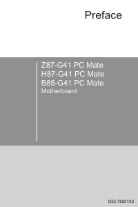
Preface
Z87-G41 PC Mate
H87-G41 PC Mate
B85-G41 PC Mate
Motherboard
G52-78501X1
Preface
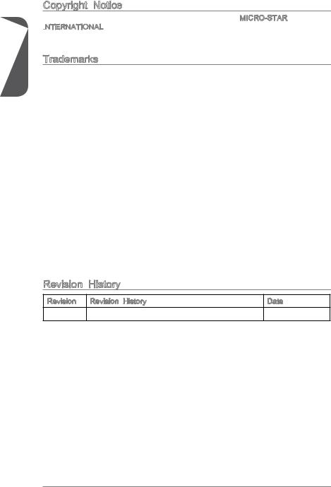
Copyright Notice
The material in this document is the intellectual property of MICRO-STAR INTERNATIONAL.

 We take every care in the preparation of this document, but no guarantee is given as to the correctness of its contents. Our products are under continual improvement and we reserve the right to make changes without notice.
Trademarks
All trademarks in this manual are properties of their respective owners.
MSI® is registered trademark of Micro-Star Int’l Co.,Ltd.
NVIDIA® is registered trademark of NVIDIA Corporation.
ATI® is registered trademark of AMD Corporation.
AMD® is registered trademarks of AMD Corporation.
Intel® is registered trademarks of Intel Corporation.
Windows® is registered trademarks of Microsoft Corporation.
AMI® is registered trademark of American Megatrends Inc.
Award® is a registered trademark of Phoenix Technologies Ltd.
Sound Blaster® is registered trademark of Creative Technology Ltd.
Realtek® is registered trademark of Realtek Semiconductor Corporation.
JMicron® is registered trademark of JMicron Technology Corporation.
Netware® is registered trademark of Novell, Inc.
Lucid® is trademark of LucidLogix Technologies, Ltd.
VIA® is registered trademark of VIA Technologies, Inc.
ASMedia® is registered trademark of ASMedia Technology Inc.
iPad, iPhone, and iPod are trademarks of Apple Inc.
Qualcomm Atheros and Killer are trademarks of Qualcomm Atheros Inc.
|
Revision |
History |
|
|
Revision |
Revision History |
Date |
|
V1.0 |
First release |
2013/04 |
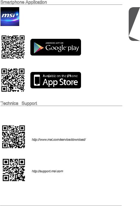
Smartphone Application
MSI+ is a smart web gadget that works as a shopping navigator and provides specs comparison for IT buyers. With a simple tap of the smartphone, you’ll efficiently locate your ideal products from a wide variety of choices and, if product details are required, you may easily download user manuals within minutes. Better yet, the power calculator provides accurate estimates of power unit capacity for DIY users.
Technical Support

 Support
If a problem arises with your system and no solution can be obtained from the user’s manual, please contact your place of purchase or local distributor. Alternatively, please try the following help resources for further guidance.
Visit the MSI website for technical guide, BIOS updates, driver updates, and other information:
http://www.msi.com/service/download/
Contact our technical staff at:
http://support.msi.com
Preface
Safety Instructions

Preface
Always read the safety instructions carefully.
Keep this User’s Manual for future reference.
Keep this equipment away from humidity.
Lay this equipment on a reliable flat surface before setting it up.
The openings on the enclosure are for air convection hence protects the equipment from overheating. DO NOT COVER THE OPENINGS.
Make sure the voltage of the power source is at 110/220V before connecting the equipment to the power inlet.
Place the power cord such a way that people can not step on it. Do not place anything over the power cord.
Always Unplug the Power Cord before inserting any add-on card or module.
All cautions and warnings on the equipment should be noted.
Never pour any liquid into the opening that can cause damage or cause electrical shock.
If any of the following situations arises, get the equipment checked by service personnel:
The power cord or plug is damaged.
Liquid has penetrated into the equipment.
The equipment has been exposed to moisture.
The equipment does not work well or you can not get it work according to User’s Manual.
The equipment has been dropped and damaged.
The equipment has obvious sign of breakage.
DONOTLEAVETHISEQUIPMENTINANENVIRONMENTABOVE60oC(140oF), IT MAY DAMAGE THE EQUIPMENT.
FCC
 -B Radio Frequency
 Interference
 Statement
This equipment has been tested and found to comply with the limits for a Class B digital device, pursuant to Part 15 of the FCC Rules. These limits are designed to provide reasonable protection against harmful interference in a residential installation. This equipment generates, uses and can radiate radio frequency energy and, if not installed and used in accordance with the instructions, may cause harmful interference to radio communications. However, there is no guarantee that interference will not occur in a particular installation. If this equipment does cause harmful interference to radio or television reception, which can be determined by turning the equipment off and on, the user is encouraged to try to correct the interference by one or more of the measures listed below.
Reorient or relocate the receiving antenna.
Increase the separation between the equipment and receiver.
Connect the equipment into an outlet on a circuit different from that to which the receiver is connected.
Consult the dealer or an experienced radio/television technician for help. Notice 1
The changes or modifications not expressly approved by the party responsible for compliance could void the user’s authority to operate the equipment.
Notice 2
Shielded interface cables and A.C. power cord, if any, must be used in order to comply with the emission limits.
VOIR LA NOTICE D’INSTALLATION AVANT DE RACCORDER AU RESEAU.
Micro-Star International
MS-7850
This device complies with Part 15 of the FCC Rules. Operation is subject to the following two conditions:
1)this device may not cause harmful interference, and
2)this device must accept any interference received, including interference that may cause undesired operation.
CE Conformity
 Conformity
Hereby, Micro-Star International CO., LTD declares that this device is in compliance with the essential safety requirements and other relevant provisions set out in the European Directive.
Preface
Preface
Radiation Exposure Statement

 Statement
This equipment complies with FCC radiation exposure limits set forth for an uncontrolled environment. This equipment and its antenna should be installed and operated with minimum distance 20 cm between the radiator and your body. This equipment and its antenna must not be co-located or operating in conjunction with any other antenna or transmitter.
European Community Compliance Statement

 Community Compliance Statement
The equipment complies with the RF Exposure Requirement 1999/519/EC, Council Recommendation of 12 July 1999 on the limitation of exposure of the general public to electromagnetic fields (0–300GHz). This wireless device complies with the R&TTE Directive.
Taiwan Wireless Statements
率、加大功率或變更原設計之特性及功能。
電通信。低功率射頻電機須忍受合法通信或工業、科學及醫療用電波輻射性電機設備之 干擾。
:
Japan VCCI Class B Statement
 Class B Statement
B
VCCIB
Korea Warning Statements
Battery Information

European Union:
Batteries, battery packs, and accumulators should not be disposed of as unsorted household waste. Please use the public collection system to return, recycle, or treat them in compliance with the local regulations.
Taiwan:
For better environmental protection, waste batteries should be collected separately for recycling or special disposal.
California, USA:
The button cell battery may contain perchlorate material and requires special handling when recycled or disposed of in California.
For further information please visit: http://www.dtsc.ca.gov/hazardouswaste/perchlorate/
CAUTION: There is a risk of explosion, if battery is incorrectly replaced.
Replace only with the same or equivalent type recommended by the manufacturer.
Chemical Substances Information
 Substances Information
In compliance with chemical substances regulations, such as the EU REACH Regulation (Regulation EC No. 1907/2006 of the European Parliament and the Council), MSI provides the information of chemical substances in products at:
http://www.msi.com/html/popup/csr/evmtprtt_pcm.html
Preface
Preface
WEEE (Waste Electrical and Electronic Equipment) Statement
 (Waste Electrical

 and Electronic
 Equipment)
 Statement
ENGLISH


To protect the global environment and as an environmentalist, MSI must remind you that…
Under the European Union (“EU”) Directive on Waste Electrical and Electronic Equipment, Directive 2002/96/EC, which takes effect on August
13, 2005, products of “electrical and electronic equipment” cannot be discarded as municipal wastes anymore, and manufacturers of covered
electronic equipment will be obligated to take back such products at the end of their useful life. MSI will comply with the product take back requirements at the end of life of MSI-branded products that are sold into the EU. You can return these products to local collection points.
DEUTSCH
Hinweis von MSI zur Erhaltung und Schutz unserer Umwelt
Gemäß der Richtlinie 2002/96/EG über Elektround Elektronik-Altgeräte dürfen Elektround Elektronik-Altgeräte nicht mehr als kommunale Abfälle entsorgt werden. MSI hat europaweit verschiedene Sammelund Recyclingunternehmen beauftragt, die in die Europäische Union in Verkehr gebrachten Produkte, am Ende seines Lebenszyklus zurückzunehmen. Bitte entsorgen Sie dieses Produkt zum gegebenen Zeitpunkt ausschliesslich an einer lokalen Altgerätesammelstelle in Ihrer Nähe.
FRANÇAIS

En tant qu’écologiste et afin de protéger l’environnement, MSI tient à rappeler ceci…
Au sujet de la directive européenne (EU) relative aux déchets des équipement électriques et électroniques, directive 2002/96/EC, prenant effet le 13 août 2005, que les produits électriques et électroniques ne peuvent être déposés dans les décharges ou tout simplement mis à la poubelle. Les fabricants de ces équipements seront obligés de récupérer certains produits en fin de vie. MSI prendra en compte cette exigence relative au retour des produits en fin de vie au sein de la communauté européenne. Par conséquent vous pouvez retourner localement ces matériels dans les points de collecte.
РУССКИЙ
Компания MSI предпринимает активные действия по защите окружающей среды, поэтому напоминаем вам, что….
В соответствии с директивой Европейского Союза (ЕС) по предотвращению загрязнения окружающей среды использованным электрическим и электронным оборудованием (директива WEEE 2002/96/EC), вступающей в силу 13
августа 2005 года, изделия, относящиеся к электрическому и электронному оборудованию, не могут рассматриваться как бытовой мусор, поэтому производители вышеперечисленного электронного оборудования обязаны принимать его для переработки по окончании срока службы. MSI обязуется соблюдать требования по приему продукции, проданной под маркой MSI на территории EC, в переработку по окончании срока службы. Вы можете вернуть эти изделия в специализированные пункты приема.
ESPAÑOL


MSI como empresa comprometida con la protección del medio ambiente, recomienda:
Bajo la directiva 2002/96/EC de la Unión Europea en materia de desechos y/o equipos electrónicos, con fecha de rigor desde el 13 de agosto de 2005, los productos clasificados como “eléctricos y equipos electrónicos” no pueden ser depositados en los contenedores habituales de su municipio, los fabricantes de equipos electrónicos, están obligados a hacerse cargo de dichos productos al termino de su período de vida. MSI estará comprometido con los términos de recogida de sus productos vendidos en la Unión Europea al final de su periodo de vida. Usted debe depositar estos productos en el punto limpio establecido por el ayuntamiento de su localidad o entregar a una empresa autorizada para la recogida de estos residuos.
NEDERLANDS
Om het milieu te beschermen, wil MSI u eraan herinneren dat….
De richtlijn van de Europese Unie (EU) met betrekking tot Vervuiling van Electrische en Electronische producten (2002/96/EC), die op 13 Augustus 2005 in zal gaan kunnen niet meer beschouwd worden als vervuiling. Fabrikanten van dit soort producten worden verplicht om producten retour te nemen aan het eind van hun levenscyclus. MSI zal overeenkomstig de richtlijn handelen voor de producten
die de merknaam MSI dragen en verkocht zijn in de EU. Deze goederen kunnen geretourneerd worden op lokale inzamelingspunten.
SRPSKI
Da bi zaštitili prirodnu sredinu, i kao preduzeće koje vodi računa o okolini i prirodnoj sredini, MSI mora da vas podesti da…
Po Direktivi Evropske unije (“EU”) o odbačenoj ekektronskoj i električnoj opremi, Direktiva 2002/96/EC, koja stupa na snagu od 13. Avgusta 2005, proizvodi koji spadaju pod “elektronsku i električnu opremu” ne mogu više biti odbačeni kao običan otpad i proizvođači ove opreme biće prinuđeni da uzmu natrag ove proizvode na kraju njihovog uobičajenog veka trajanja. MSI će poštovati zahtev o preuzimanju ovakvih proizvoda kojima je istekao vek trajanja, koji imaju MSI oznaku i koji su prodati u EU. Ove proizvode možete vratiti na lokalnim mestima za prikupljanje.
POLSKI

Aby chronić nasze środowisko naturalne oraz jako firma dbająca o ekologię, MSI przypomina, że…
Zgodnie z Dyrektywą Unii Europejskiej (“UE”) dotyczącą odpadów produktów elektrycznych i elektronicznych (Dyrektywa 2002/96/EC), która wchodzi w życie 13 sierpnia 2005, tzw. “produkty oraz wyposażenie elektryczne i elektroniczne “ nie mogą być traktowane jako śmieci komunalne, tak więc producenci tych produktów będą zobowiązani do odbierania ich w momencie gdy produkt jest wycofywany z użycia. MSI wypełni wymagania UE, przyjmując produkty (sprzedawane na terenie Unii Europejskiej) wycofywane z użycia. Produkty MSI będzie można zwracać w wyznaczonych punktach zbiorczych.
Preface

Preface
TÜRKÇE

Çevreci özelliğiyle bilinen MSI dünyada çevreyi korumak için hatırlatır:
Avrupa Birliği (AB) Kararnamesi Elektrik ve Elektronik Malzeme Atığı, 2002/96/EC Kararnamesi altında 13 Ağustos 2005 tarihinden itibaren geçerli olmak üzere, elektrikli ve elektronik malzemeler diğer atıklar gibi çöpe atılamayacak ve bu elektonik cihazların üreticileri, cihazların kullanım süreleri bittikten sonra ürünleri geri toplamakla yükümlü olacaktır. Avrupa Birliği’ne satılan MSI markalı ürünlerin kullanım süreleri bittiğinde MSI ürünlerin geri alınması isteği ile işbirliği içerisinde olacaktır. Ürünlerinizi yerel toplama noktalarına bırakabilirsiniz.
ČESKY
Záleží nám na ochraně životního prostředí — společnost MSI upozorňuje…
Podle směrnice Evropské unie (“EU”) o likvidaci elektrických a elektronických výrobků 2002/96/EC platné od 13. srpna 2005 je zakázáno likvidovat “elektrické a elektronické výrobky” v běžném komunálním odpadu a výrobci elektronických výrobků, na které se tato směrnice vztahuje, budou povinni odebírat takové výrobky zpět po skončení jejich životnosti. Společnost MSI splní požadavky na odebírání výrobků značky MSI, prodávaných v zemích EU, po skončení jejich životnosti. Tyto výrobky můžete odevzdat v místních sběrnách.
MAGYAR
Annak érdekében, hogy környezetünket megvédjük, illetve környezetvédőként fellépve az MSI emlékezteti Önt, hogy …
Az Európai Unió („EU”) 2005. augusztus 13-án hatályba lépő, az elektromos és elektronikus berendezések hulladékairól szóló 2002/96/EK irányelve szerint az elektromos és elektronikus berendezések többé nem kezelhetőek lakossági hulladékként, és az ilyen elektronikus berendezések gyártói kötelessé válnak az
ilyen termékek visszavételére azok hasznos élettartama végén. Az MSI betartja a termékvisszavétellel kapcsolatos követelményeket az MSI márkanév alatt az EU-n belül értékesített termékek esetében, azok élettartamának végén. Az ilyen termékeket a legközelebbi gyűjtőhelyre viheti.
ITALIANO

Per proteggere l’ambiente, MSI, da sempre amica della natura, ti ricorda che….
In base alla Direttiva dell’Unione Europea (EU) sullo Smaltimento dei Materiali Elettrici ed Elettronici, Direttiva 2002/96/EC in vigore dal 13 Agosto 2005, prodotti appartenenti alla categoria dei Materiali Elettrici ed Elettronici non possono più essere eliminati come rifiuti municipali: i produttori di detti materiali saranno obbligati a ritirare ogni prodotto alla fine del suo ciclo di vita. MSI si adeguerà a tale Direttiva ritirando tutti i prodotti marchiati MSI che sono stati venduti all’interno dell’Unione Europea alla fine del loro ciclo di vita. È possibile portare i prodotti nel più vicino punto di raccolta
![]()
Contents
Preface i
Copyright Notice ii Trademarks ii Revision History ii Smartphone Application iii Technical Support iii Safety Instructions iv FCC-B Radio Frequency Interference Statement v CE Conformity v Radiation Exposure Statement vi European Community Compliance Statement vi Taiwan Wireless Statements vi Japan VCCI Class B Statement vi Korea Warning Statements vi Battery Information vii Chemical Substances Information vii WEEE (Waste Electrical and Electronic Equipment) Statement viii
Chapter 1 Getting Started 1-1
Packing Contents 1-2 Optional Accessories 1-2 Assembly Precautions 1-3 Motherboard Specifications 1-4 Connectors Quick Guide 1-7 Back Panel Quick Guide 1-9 CPU (Central Processing Unit) 1-11
Introduction to the LGA 1150 CPU 1-11 CPU & Heatsink Installation 1-12 Memory 1-15 Dual-Channel mode Population Rule 1-15 Mounting Screw Holes 1-16 Power Supply 1-17 JPWR1~2: ATX Power Connectors 1-17 Expansion Slots 1-18 PCI_E1~4: PCIe Expansion Slots 1-18 Video/ Graphics Cards 1-19 Single Video Card Installation 1-19 AMD CrossFire™ (Multi-GPU) Technology 1-20 Internal Connectors 1-22 SATA1~6: SATA Connectors 1-22
Preface
Preface
CPUFAN1~2,SYSFAN1~3: Fan Power Connectors 1-23 JFP1, JFP2: System Panel Connectors 1-24 JUSB1~2: USB 2.0 Expansion Connectors 1-25 JCI1: Chassis Intrusion Connector 1-26 JTPM1: TPM Module Connector 1-27 JLPT1: Parallel Port Connector 1-28
Jumpers 1-29 JBAT1: Clear CMOS Jumper 1-29 Drivers and Utilities 1-30 Total Installer 1-30
Chapter 2 Quick Installation
 2-1
2-1
CPU Installation 2-2 Memory Installation 2-4 Motherboard Installation 2-5 Power Connectors Installation 2-7 SATA HDD Installation 2-9 mSATA SSD Installation 2-10 Front Panel Connector Installation 2-11
JFP1 Connecotr Installation 2-11 Front Panel Audio Connector Installation 2-11 Peripheral Connector Installation 2-12 USB2.0 Connector Installation 2-12 USB3.0 Connector Installation 2-12 Graphics Card Installation 2-13
Chapter 3 BIOS Setup 3-1
Entering Setup 3-2
Entering BIOS Setup 3-2
Overview 3-3
Operation 3-5
SETTINGS 3-6
System Status 3-6
Advanced 3-7
Boot 3-15
Security 3-15
Save & Exit 3-16
OC 3-17
M-FLASH 3-25
OC PROFILE 3-26
HARDWARE MONITOR 3-27
Appendix A Intel
 SBA (optional) A-1
Prerequisites A-2 Installing Intel SBA A-3 Software Configuration A-3 Software panel overview A-3 Password settings A-4 Help Button A-4
Appendix B Intel


 RAID (optional) B-1
Introduction B-2 Using Intel Rapid Storage Technology Option ROM B-3 Degraded RAID Array B-10 System Acceleration (optional) B-12 RST Synchronization (optional) B-14
Preface

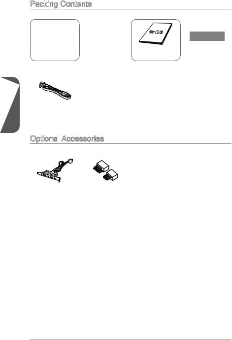
Packing Contents
1 Chapter
|
Motherboard |
Drivers & Utilities |
Motherboard |
I/O Shield |
|
Disc |
User Guide |
SATA Cable
Optional Accessories
 Accessories
|
USB 3.0 Bracket |
M-Connector |
*These pictures are for reference only and may vary without notice.
*The packing contents may vary according to the model you purchased.
*If you need to purchase the optional accessories or request part numbers, please visit the MSI website at http://www.msi.com/index.php or consult the dealer.
Assembly Precautions
|
■ The components included in this package are prone to damage from electrostatic |
||
|
discharge (ESD). Please adhere to the following instructions to ensure successful |
||
|
computer assembly. |
||
|
■ Always turn off the power supply and unplug the power cord from the power outlet |
||
|
before installing or removing any computer component. |
||
|
■ Ensure that all components are securely connected. Loose connections may cause |
||
|
the computer to not recognize a component or fail to start. |
||
|
■ Hold the motherboard by the edges to avoid touching sensitive components. |
||
|
■ It is recommended to wear an electrostatic discharge (ESD) wrist strap when |
||
|
handling the motherboard to prevent electrostatic damage. If an ESD wrist strap is |
||
|
not available, discharge yourself of static electricity by touching another metal object |
||
|
before handling the motherboard. |
||
|
■ Store the motherboard in an electrostatic shielding container or on an antistatic pad |
1 |
|
|
whenever the motherboard is not installed. |
||
|
Chapter |
||
|
■ Before turning on the computer, ensure that there are no loose screws or metal |
||
|
components on the motherboard or anywhere within the computer case. |
||
|
■ Do not use the computer in a high-temperature environment. |
||
|
■ Do not boot the computer before installation is completed. This could cause |
||
|
permanent damage to the components as well as injury to the user. |
||
|
■ If you need help during any installation step, please consult a certified computer |
||
|
technician. |
Important
A screwdriver (not included) may be required for computer assembly.
1 Chapter
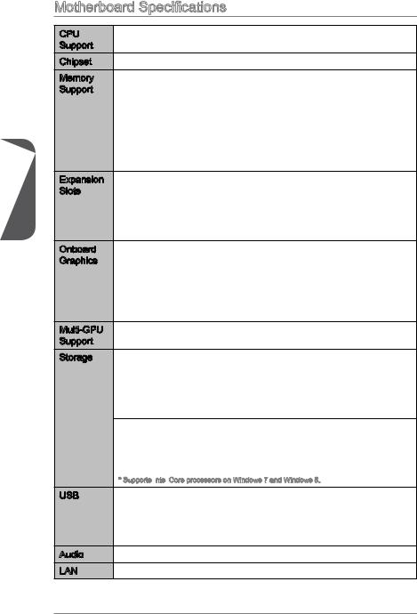
Motherboard Specifications
|
CPU |
■ 4th Generation Intel® Core™ i7 / Core™ i5 / Core™ i3 / Pentium® / |
|
Support |
Celeron® processors for LGA 1150 socket |
|
Chipset |
■ Intel® Z87/ H87/ B85 Express Chipset |
|
Memory |
■ 4x DDR3 memory slots supporting up to 32GB |
|
Support |
■ Z87-G41 PC Mate supports DDR3 3000(OC)/ 2800(OC)/ 2666(OC)/ |
|
2600(OC)/ 2400(OC)/ 2200(OC)/ 2133(OC)/ 2000(OC)/ 1866(OC)/ |
|
|
1600/ 1333/ 1066 MHz |
|
|
■ H87-G41 PC Mate and B85-G41 PC Mate supports DDR3 1600/ |
|
|
1333/ 1066 MHz |
|
|
■ Dual channel memory architecture |
|
|
■ Supports non-ECC, un-buffered memory |
|
|
■ Supports Intel® Extreme Memory Profile (XMP) |
|
Expansion |
■ 2x PCIe x16 slots |
|
Slots |
— PCI_E2 supports PCIe 3.0 |
|
— PCI_E4 supports PCIe 2.0 |
|
|
— Support x16, x4/x4 modes |
|
|
■ 2x PCIe 2.0 x1 slots |
|
|
■ 2x PCI slots |
|
|
Onboard |
■ 1x VGA port, supporting a maximum resolution of 1920×1200 @ |
|
Graphics |
60Hz, 24bpp |
|
■ 1x DVI-D port, supporting a maximum resolution of 1920×1200 @ |
|
|
60Hz, 24bpp |
|
|
■ 1x HDMI port, supporting a maximum resolution of |
|
|
4096×2160@24Hz, 24bpp/ 2560×1600@60Hz, 24bpp/ |
|
|
1920×1080@60Hz, 36bpp |
|
|
Multi-GPU |
■ Supports AMD CrossFireTM Technology |
|
Support |
|
|
Storage |
■ Z87-G41 PC Mate/ H87-G41 PC Mate |
—Intel Z87/ H87 Express Chipset
—6x SATA 6Gb/s ports (SATA1~6)
—Supports RAID 0, RAID1, RAID 5 and RAID 10
—Supports Intel Smart Response Technology, Intel Rapid Start Technology and Intel Smart Connect Technology*
■B85-G41 PC Mate
—Intel B85 Express Chipset
—4x SATA 6Gb/s ports (SATA1, SATA2, SATA3, SATA4)
—2x SATA 3Gb/s ports (SATA5, SATA6)
—Supports Intel Smart Connect Technology*
* Supports Intel
 Core processors on Windows 7 and Windows 8.
|
USB |
■ Intel Z87/ H87/ B85 Express Chipset |
—4x USB 3.0 ports (2 ports on the back panel, 2 ports available through the internal USB connectors)
—8x USB 2.0 ports (4 ports on the back panel, 4 ports available through the internal USB connectors)
|
Audio |
■ Realtek® ALC887 Codec |
|
LAN |
■ Realtek® RTL8111G Gigabit LAN controller |
|
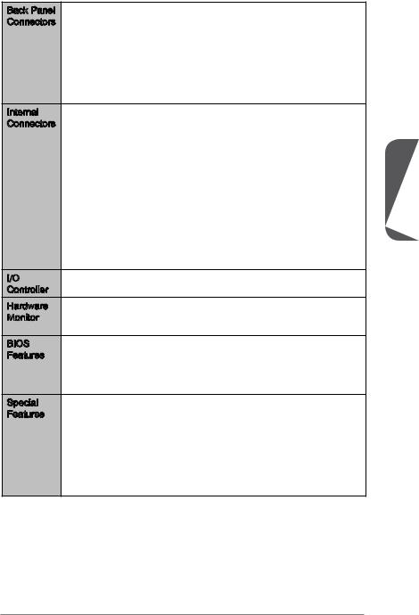
Back Panel |
■ 1x PS/2 mouse port |
|
Connectors |
■ 1x PS/2 keyboard port |
|
■ 4x USB 2.0 ports |
|
|
■ 2x USB 3.0 ports |
|
|
■ 1x HDMI port |
|
|
■ 1x VGA port |
|
|
■ 1x DVI-D port |
|
|
■ 1x LAN (RJ45) port |
|
|
■ 3x audio jacks |
|
|
Internal |
■ 1x 24-pin ATX main power connector |
|
Connectors |
■ 1x 8-pin ATX 12V power connector |
|
■ 6x SATA connectors |
|
|
■ 2x USB 2.0 connectors (supports additional 4 USB 2.0 ports) |
|
|
■ 1x USB 3.0 connector (supports additional 2 USB 3.0 ports) |
|
|
■ 2x 4-pin CPU fan connectors |
|
|
■ 1x 4-pin system fan connector |
|
|
■ 2x 3-pin system fan connectors |
|
|
■ 1x Clear CMOS jumper |
|
|
■ 1x Front panel audio connector |
|
|
■ 2x System panel connectors |
|
|
■ 1x Chassis Intrusion connector |
|
|
■ 1x TPM module connector |
|
|
■ 1x Serial port connector |
|
|
■ 1x Parallel Port connector |
|
|
I/O |
■ NUVOTON NCT6779 Controller Chip |
|
Controller |
|
|
Hardware |
■ CPU/System temperature detection |
|
Monitor |
■ CPU/System fan speed detection |
|
■ CPU/System fan speed control |
|
|
BIOS |
■ 64 Mb flash (for Z87-G41 PC Mate) |
|
Features |
■ 128 Mb flash (for H87-G41 PC Mate/ B85-G41 PC Mate) |
|
■ UEFI AMI BIOS |
|
|
■ ACPI 5.0, PnP 1.0a, SM BIOS 2.7, DMI 2.0 |
|
|
■ Multi-language |
|
|
Special |
■ Military Class 4 |
|
Features |
■ OC Genie 4 |
|
■ Click BIOS 4 |
|
|
■ AMD CrossFire |
|
|
■ Sound Blaster Cinema (for Z87-G41 PC Mate) |
|
|
■ Clear CMOS Button |
|
|
■ Total Fan Control |
|
|
■ Super RAID |
|
|
■ Command Center |
Chapter 1
1 Chapter
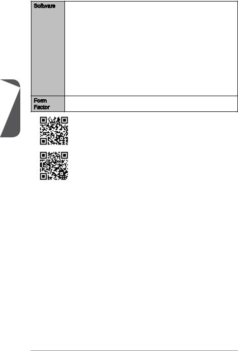
■MSI
—Command Center
—Super Charger
—Super RAID
—Live Update 5
—Fast Boot
■7-ZIP
■Intel Extreme Tuning Utility
■Norton Internet Security Solution
■Trend Micro SafeSync
■Sound Blaster Cinema (for Z87-G41 PC Mate)
■Network genie
■Small Business Advantage (for H87-G41 PC Mate/ B85-G41 PC Mate)
|
Form |
■ ATX Form Factor |
|
Factor |
■ 12 in. x 8.7 in. (30.5 cm x 22 cm) |
For the latest information about CPU, please visit
http://www.msi.com/service/cpu-support/
For more information on compatible components, please visit http://www.msi.com/service/test-report/
![]()
Connectors Quick Guide
|
DIMM3 |
||
|
CPU Socket |
DIMM2 |
DIMM4 |
|
DIMM1 |
|
SYSFAN1 |
CPUFAN2 |
|
JPWR2 |
CPUFAN1 |
|
SYSFAN3 |
|
|
JPWR1 |
|
|
JUSB3 |
|
|
SATA1 |
|
|
SATA2 |
|
|
SATA3_4 |
|
|
SATA5_6 |
|
|
JCI1 |
|
JAUD1 |
JTPM1 |
JFP1 |
|
JCOM1 |
JBAT1 |
JFP2 |
|
JLPT1 |
SYSFAN2 |
JUSB2 |
|
JUSB1 |
Chapter 1
1 Chapter
Connectors Reference Guide
|
Port Name |
Port Type |
Page |
|
Back Panel |
1-9 |
|
|
CPU |
LGA1150 CPU Socket |
1-11 |
|
CPUFAN1~2,SYSFAN1~3 |
Fan Power Connectors |
1-25 |
|
DIMM1~4 |
DDR3 Memory Slots |
1-15 |
|
JAUD1 |
Front Panel Audio Connector |
1-28 |
|
JBAT1 |
Clear CMOS Jumper |
1-31 |
|
JCI1 |
Chassis Intrusion Connector |
1-28 |
|
JCOM1 |
Serial Port Connector |
1-29 |
|
JFP1, JFP2 |
System Panel Connectors |
1-26 |
|
JLPT1 |
Parallel Port Connector |
1-30 |
|
JPWR1~2 |
ATX Power Connectors |
1-17 |
|
JTPM1 |
TPM Module Connector |
1-29 |
|
JUSB1~2 |
USB 2.0 Expansion Connector |
1-27 |
|
JUSB3 |
USB 3.0 Expansion Connector |
1-27 |
|
PCI_E2,4 |
PCIe x16 Expansion Slots |
1-18 |
|
PCI_E1,3 |
PCIe x1 Expansion Slots |
1-18 |
|
PCI1~2 |
PCI Expansion Slots |
1-18 |
|
SATA1~6 |
SATA Connectors |
1-24 |

Back Panel Quick Guide
 Quick Guide
|
PS/2 Mouse Port |
VGA Port |
LAN Port |
|
USB 2.0 Port |
Line-In |
|
USB 3.0 Port |
|
|
Line-Out |
|
|
HDMI |
|
|
Mic |
|
PS/2 Keyboard Port |
DVI-D Port |
PS/2 Mouse/ Keyboard Port
PS/2® mouse/ keyboard DIN connector for a PS/2® mouse/ keyboard.
USB 2.0 Port
The USB 2.0 port is for attaching USB 2.0 devices such as keyboard, mouse, or other USB 2.0-compatible devices.
USB 3.0 Port
USB 3.0 port is backward-compatible with USB 2.0 devices. It supports data transfer rate up to 5 Gbit/s (SuperSpeed).
Important
In order to use USB 3.0 devices, you must connect to a USB 3.0 port. If a USB cable is used, it must be USB 3.0 compliant.
HDMI
 Port
Port 


The High-Definition Multimedia Interface (HDMI) is an all-digital audio-video interface that is capable of transmitting uncompressed streams. HDMI supports all types of TV formats, including standard, enhanced, or high-definition video, plus multi-channel digital audio on a single cable.
VGA Port
The DB15-pin female connector is provided for monitor.
DVI
 -D Port
The DVI-D (Digital Visual InterfaceDigital) connector can be connected to a LCD monitor, or a CRT monitor with an adapter. To connect a monitor, please refer to the monitor’s manual for more information.
Chapter 1
1 Chapter
Important
This platform supports dual-display and triple-display function.
|
HDMI+VGA |
HDMI+DVI |
VGA+DVI |
HDMI+VGA+DVI |
||
|
Extend mode |
|||||
|
(Extend the desktop to the second |
|||||
|
and thired monitor) |
|||||
|
Clone mode |
|||||
|
(Monitors have the same screen) |
|||||
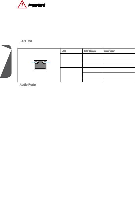
LAN
 Port
Port
The standard RJ-45 LAN jack is for connecting to a Local Area Network (LAN).
|
LED |
LED Status |
Description |
|
|
Off |
No link |
||
|
LINK/ACT |
SPEED Link/ Activity LED |
Yellow |
Linked |
|
LED |
LED |
Blinking |
Data activity |
|
Off |
10 Mbps connection |
||
|
Speed LED |
Green |
100 Mbps connection |
|
|
Orange |
1 Gbps connection |
Audio Ports
These connectors are used for audio devices. The color of the jack refers to the function of the connector.
■Blue-Line in: Used for connecting external audio outputting devices.
■GreenLine out: Used as a connector for speakers or headphone.
■PinkMic: Used as a connector for a microphone.
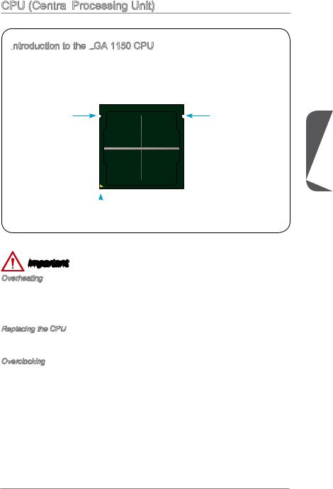
CPU (Central Processing Unit)
 Processing Unit)
Introduction to the LGA 1150 CPU

 to the LGA
 1150 CPU
The surface of the LGA 1150 CPU has two notches and a golden triangle to assist in correctly lining up the CPU for motherboard placement. The golden triangle is the Pin 1 indicator.
Chapter 1
 Golden triangle is the Pin 1 indicator
Important
Overheating
Overheating can seriously damage the CPU and motherboard. Always make sure the cooling fans work properly to protect the CPU from overheating. Be sure to apply an even layer of thermal paste (or thermal tape) between the CPU and the heatsink to enhance heat dissipation.
Replacing the CPU
When replacing the CPU, always turn off the system’s power supply and unplug the power supply’s power cord to ensure the safety of the CPU.
Overclocking
This motherboard is designed to support overclocking. Before attempting to overclock, please make sure that all other system components can tolerate overclocking. Any attempt to operate beyond product specifications is not recommend. MSI does not guarantee the damages or risks caused by inadequate operation beyond product specifications.
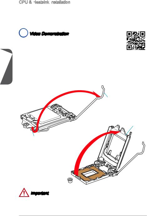
CPU & Heatsink Installation
 Installation
When installing a CPU, always remember to install a CPU heatsink. A CPU heatsink is necessary to prevent overheating and maintain system stability. Follow the steps below to ensure correct CPU and heatsink installation. Wrong installation can damage both the CPU and the motherboard.
 Video Demonstration
Watch the video to learn how to install CPU & heatsink. at the address below.
http://youtu.be/bf5La099urI
|
1Chapter |
1. |
position. |
|
Push the load lever down to unclip it and lift to the fully open position. |
||
|
2. |
The load plate will automatically lift up as the load lever is pushed to the fully open |
Load lever
Load plate
Retention tab
Important
Do not touch the socket contacts or the bottom of the CPU.

3.Align the notches with the socket alignment keys. Lower the CPU straight down, without tilting or sliding the CPU in the socket. Inspect the CPU to check if it is properly seated in the socket.
4.Close and slide the load plate under the retention knob. Close and engage the load lever.
CPU notches
Chapter 1
Alignment Key
Retention knob
5.When you press down the load lever the PnP cap will automatically pop up from the CPU socket. Do not discard the PnP cap. Always replace the PnP cap if the CPU is removed from the socket.
6.Evenly spread a thin layer of thermal paste (or thermal tape) on the top of the CPU. This will help in heat dissipation and prevent CPU overheating.
PnP cap
Thermal paste
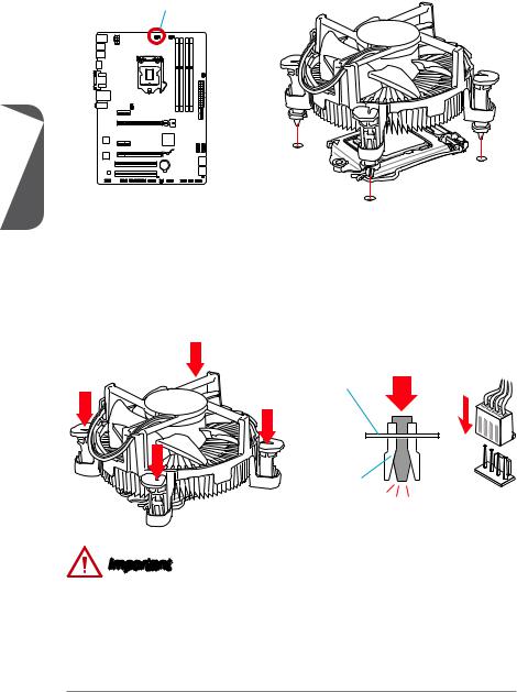
7.Locate the CPU fan connector on the motherboard.
8.Place the heatsink on the motherboard with the fan’s cable facing towards the fan connector and the fasteners matching the holes on the motherboard.
CPU fan connector
1 Chapter
9.Push down the heatsink until the four fasteners get wedged into the holes on the motherboard. Press the four fasteners down to fasten the heatsink. As each fastener locks into position a click should be heard.
10.Inspect the motherboard to ensure that the fastener-ends have been properly locked in place.
11.Finally, attach the CPU fan cable to the CPU fan connector on the motherboard.
Motherboard
Fastener-end
Important
•Confirm that the CPU heatsink has formed a tight seal with the CPU before booting your system.
•Whenever the CPU is not installed, always protect the CPU socket pins by covering the socket with the plastic cap.
•If you purchased a separate CPU and heatsink/ cooler, Please refer to the documentation in the heatsink/ cooler package for more details about installation.
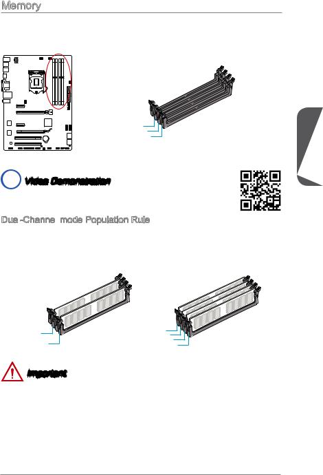
Memory
These DIMM slots are used for installing memory modules. For more information on compatible components, please visit http://www.msi.com/service/test-report/
DIMM1
DIMM2
DIMM3
DIMM4
 Video Demonstration
Watch the video to learn how to install memories at the address below. http://youtu.be/76yLtJaKlCQ
Dual-Channel mode Population Rule
 -Channel
 mode Population Rule
In Dual-Channel mode, the memory modules can transmit and receive data with two data bus channels simultaneously. Enabling Dual-Channel mode can enhance system performance. The following illustrations explain the population rules for Dual-Channel mode.
Chapter 1
|
DIMM2 |
DIMM1 |
|
DIMM2 |
|
|
DIMM4 |
DIMM3 |
|
DIMM4 |
Important
•DDR3 memory modules are not interchangeable with DDR2, and the DDR3 standard is not backward compatible. Always install DDR3 memory modules in DDR3 DIMM slots.
•To ensure system stability, memory modules must be of the same type and density in Dual-Channel mode.
•Due to chipset resource usage, the system will only detect up to 31+ GB of memory (not full 32 GB) when all DIMM slots have 8GB memory modules installed.
1 Chapter
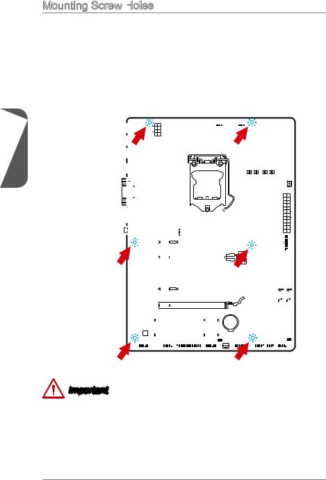
Mounting Screw Holes

When installing the motherboard, first install the necessary mounting stands required for an motherboard on the mounting plate in your computer case. If there is an
I/O back plate that came with the computer case, please replace it with the I/O backplate that came with the motherboard package. The I/O backplate should snap easily into the computer case without the need for any screws. Align the mounting plate’s mounting stands with the screw holes on the motherboard and secure the motherboard with the screws provided with your computer case. The locations of the screw holes on the motherboard are shown below. For more information, please refer to the manual that came with the computer case.
|
computer |
||||||||||||||||||||||||||||||||||||||||||||||||||||||||||||||||||||||||||||||||||||||||||
|
facing |
upwiththe |
|||||||||||||||||||||||||||||||||||||||||||||||||||||||||||||||||||||||||||||||||||||||||
|
theof |
backplate.I/O |
|||||||||||||||||||||||||||||||||||||||||||||||||||||||||||||||||||||||||||||||||||||||||
|
be |
line |
|||||||||||||||||||||||||||||||||||||||||||||||||||||||||||||||||||||||||||||||||||||||||
|
TheI/O portsshould towardthe rear case.They should holeson the |
||||||||||||||||||||||||||||||||||||||||||||||||||||||||||||||||||||||||||||||||||||||||||
Important
•Install the motherboard on a flat surface free from unnecessary debris.
•To prevent damage to the motherboard, any contact between the motherboard circuitry and the computer case, except for the mounting stands, is prohibited.
•Please make sure there are no loose metal components on the motherboard or within the computer case that may cause a short circuit of the motherboard.
![]()
Power Supply
 Video Demonstration
Watch the video to learn how to install power supply connectors. http://youtu.be/gkDYyR_83I4
JPWR1~2: ATX Power Connectors

 ATX Power Connectors
These connectors allow you to connect an ATX power supply. To connect the ATX power supply, align the power supply cable with the connector and firmly press the cable into the connector. If done correctly, the clip on the power cable should be hooked on the motherboard’s power connector.
|
4 |
|||
|
. |
|||
|
3 |
Ground |
||
|
. |
|||
|
2 |
Ground |
||
|
. |
|||
|
1 |
Ground |
||
|
. |
|||
|
Ground |
JPWR2
|
8 |
||||
|
5 |
. |
|||
|
7 |
+12V |
|||
|
. |
||||
|
6 |
+12V |
|||
|
. |
||||
|
+12V |
||||
|
. |
||||
|
+12V |
|
12 |
||||||||||||
|
11 |
. |
|||||||||||
|
7 |
10 |
. +3. |
||||||||||
|
+12V |
||||||||||||
|
9 . |
3V |
|||||||||||
|
8 |
. |
|||||||||||
|
6 . |
||||||||||||
|
5 . |
||||||||||||
|
1 |
4 |
. +5 |
||||||||||
|
3 . |
Ground |
|||||||||||
|
2 |
. +5 |
|||||||||||
|
.GroundV |
||||||||||||
|
. |
V |
|||||||||||
|
. +3 |
3 |
|||||||||||
|
+3 |
||||||||||||
|
. |
||||||||||||
|
3 |
||||||||||||
|
V |
|
.Ground |
||||
|
. |
— |
|||
|
13. |
— |
ON |
||
|
+3 |
12V |
# |
||
|
3 |
||||
|
V |
JPWR1
|
24 |
||||
|
23 |
. |
|||
|
. |
Ground |
|||
|
. +5 |
V |
|||
|
+5 |
||||
|
+5 |
V |
V |
Important
Make sure that all the power cables are securely connected to a proper ATX power supply to ensure stable operation of the motherboard.
Chapter 1

1 Chapter
Expansion Slots

 Slots
SlotsThis motherboard contains numerous slots for expansion cards, such as discrete graphics or audio cards.
PCI_E1~4: PCIe Expansion Slots
 _E1~4:

 PCIe Expansion
 Slots
SlotsThe PCIe slot supports the PCIe interface expansion card.

 PCIe 3.0 x16 Slot
PCIe 2.0 x16 Slot
PCIe 2.0 x1 Slot
PCI1~2: PCI
PCI Expansion
 Slots
Slots
The PCI slot supports the PCI interface expansion card..
PCI Slot
Important
When adding or removing expansion cards, always turn off the power supply and unplug the power supply power cable from the power outlet. Read the expansion card’s documentation to check for any necessary additional hardware or software changes.
 Loading…
- Manuals
- Brands
- MSI Manuals
- Motherboard
- Z87-G41 PC Mate
Manuals and User Guides for MSI Z87-G41 PC Mate. We have 2 MSI Z87-G41 PC Mate manuals available for free PDF download: Preface, User Manual
В представленном списке руководства для конкретной модели Материнской платы — MSI H87-G41 PC Mate. Вы можете скачать инструкции к себе на компьютер или просмотреть онлайн на страницах сайта бесплатно или распечатать.
- Инструкции и файлы
- Характеристики
- Основные поломки
- Сервисы по ремонту
В случае если инструкция на русском не полная или нужна дополнительная информация по этому устройству, если вам нужны
дополнительные файлы: драйвера, дополнительное руководство пользователя (производители зачастую для каждого
продукта делают несколько различных документов технической помощи и руководств), свежая версия прошивки, то
вы можете задать вопрос администраторам или всем пользователям сайта, все постараются оперативно отреагировать
на ваш запрос и как можно быстрее помочь. Ваше устройство имеет характеристики:Socket: LGA1150, Поддерживаемые процессоры: Intel Core i7/Core i5/Core i3/Pentium/Celeron, Поддержка многоядерных процессоров: есть, Чипсет: Intel H87, Поддержка SLI/CrossFire: CrossFire, Память: DDR3 DIMM, 1066 — 1600 МГц, полные характеристики смотрите в следующей вкладке.
Для многих товаров, для работы с MSI H87-G41 PC Mate могут понадобиться различные дополнительные файлы: драйвера, патчи, обновления, программы установки. Вы можете скачать онлайн эти файлы для конкретнй модели MSI H87-G41 PC Mate или добавить свои для бесплатного скачивания другим посетителями.
Если вы не нашли файлов и документов для этой модели то можете посмотреть интсрукции для похожих товаров и моделей, так как они зачастую отличаются небольшим изменениями и взаимодополняемы.
Обязательно напишите несколько слов о преобретенном вами товаре, чтобы каждый мог ознакомиться с вашим отзывом или вопросом. Проявляйте активность что как можно бльше людей смогли узнать мнение настоящих людей которые уже пользовались MSI H87-G41 PC Mate.
Основные и самые важные характеристики модели собраны из надежных источников и по характеристикам можно найти похожие модели.
| Процессор | |
| Socket | LGA1150 |
| Поддерживаемые процессоры | Intel Core i7/Core i5/Core i3/Pentium/Celeron |
| Поддержка многоядерных процессоров | есть |
| Чипсет | |
| Чипсет | Intel H87 |
| Поддержка SLI/CrossFire | CrossFire |
| Память | |
| Память | DDR3 DIMM, 1066 — 1600 МГц |
| Количество слотов памяти | 4 |
| Поддержка двухканального режима | есть |
| Максимальный объем памяти | 32 Гб |
| Дисковые контроллеры | |
| IDE | нет |
| SATA | количество разъемов SATA 6Gb/s: 6, RAID: 0, 1, 5, 10 на основе Intel H87 |
| Слоты расширения | |
| Слоты расширения | 2xPCI-E x16, 2xPCI-E x1, 2xPCI |
| Поддержка PCI Express 2.0 | есть |
| Поддержка PCI Express 3.0 | есть |
| Аудио/видео | |
| Звук | 7.1CH, HDA, на основе Realtek ALC887 |
| Сеть | |
| Ethernet | 1000 Мбит/с, на основе Realtek 8111G |
| Подключение | |
| Наличие интерфейсов | 12 USB, из них 4 USB 3.0 (2 на задней панели), 1xCOM, D-Sub, DVI, HDMI, Ethernet, PS/2 (клавиатура), PS/2 (мышь), LPT |
| Разъемы на задней панели | 6 USB, из них 2 USB 3.0, D-Sub, DVI, HDMI, Ethernet, PS/2 (клавиатура), PS/2 (мышь) |
| Основной разъем питания | 24-pin |
| Разъем питания процессора | 8-pin |
| Тип системы охлаждения | пассивное |
| Дополнительные параметры | |
| Форм-фактор | ATX |
Здесь представлен список самых частых и распространенных поломок и неисправностей у Материнских плат. Если у вас такая поломка то вам повезло, это типовая неисправность для MSI H87-G41 PC Mate и вы можете задать вопрос о том как ее устранить и вам быстро ответят или же прочитайте в вопросах и ответах ниже.
| Название поломки | Описание поломки | Действие |
|---|---|---|
| Разрыв Печатных Проводников | ||
| Обрыв Конденсаторов Или Резисторов | ||
| Короткое Замыкание В Электрических Цепях | ||
| Разрушение Разъемов И Слотов | ||
| Поломка Процессорного Разъема | ||
| Выгорание Портов | ||
| Микротрещины В Плате | ||
| Выход Из Строя Сетевого Адаптера | ||
| Перегрев Компонентов | ||
| Не Запускается При Включении | При Включении Не Загружается. В Биос Не Входит. Пост Код — А3 | |
| Какой Компонент | Подскажите Марку Траyзистора Q46? | |
| Не Работает Ps/2 | Сначала Отвалилась Клавиатура, А Через Некоторое Время 6 Коротких Гудков И Не Запускается | |
| Подключить Переднюю Панель | Не Могу Подключить Переднюю Панель | |
| Судя По Всему Отвал Биоса | Материнка Стартует Секунд На 5,Кулер Процессора Берет Обороты И Останавливается.и Так-Циклически,Без Остановок.запуск Невозможен.вечером Либо Завтра Буду Пытаться Его Восстановить,Потом Может Дополню | |
| Пропал Звук На Материнке | Пропал Звук На Материнке, Отображается Только Nvidia Hdmi. Переустановка Драйверов С Офсайта Не Помогла. | |
| Биос | При Старте Звук Через Промежетки Времени Примерно В 1-3 Мин Три Сигнала Потом Стартует Винда , Недавно Вообще Написал Cmos Setting Wrong И C7, Жму Del Меняется На B2 Чтоб Воити В Биос Три Сигнала По Одному Через Промеежутки Времени 1-3 Мин И Черный Экра | |
| Asus M2A-Vm Hdmi | Не Запускается Процессор Phenom Ii X4 945 Rev. C3, На Socket-Ам 3, Нет Даже Сигнала, Черный Экран | |
| Не Включается | После Замены Конденсаторов С34 И С35 Не Включается | |
| Черный Экран | Все Уже Перепробовал И Озу Менял И Переставлял И Ластиком Чистил, И Батарейку Вынимал И Измерял, И Видеокарту С Бп На Заведомо Годную Ставил Исход Один, Черный Экран И Speaker Издает 1 Длинный 2 Коротких, Если Я Не Путаю. | |
| Неправильно Отображается Память | При Установленной Памяти 4 Гигабайта В Биосе Отображается 8. Установил Одну Планку 2 Гига — Отображается 4 | |
В нашей базе сейчас зарегестрированно 18 353 сервиса в 513 города России, Беларусии, Казахстана и Украины.

ДЕМАЛ-СЕРВИС В ПЕРОВО
⭐
⭐
⭐
⭐
⭐
Адресс:
1-я владимирская д. 41
Телефон:
74951337215
Сайт:
n/a
Время работы
Будни: с 0945 до 1845
Суббота: с 1015 до 1545
Воскресенье: с 1015 до 1545
ASUS
⭐
⭐
⭐
⭐
⭐
Адресс:
Старокачаловская улица, д.3 к.2
Телефон:
74999630187
Сайт:
n/a
Время работы
Время работы не указано
ASUS24
⭐
⭐
⭐
⭐
⭐
Адресс:
ул. Нижегородская 29-33 стр.2
Телефон:
74956697492
Сайт:
n/a
Время работы
Будни: с 1000 до 1900
Суббота: с 1000 до 1600
Воскресенье: выходной
73 МАСТЕРА
⭐
⭐
⭐
⭐
⭐
Адресс:
Самеда Вургуна ул., д.5
Телефон:
74997098250
Сайт:
n/a
Время работы
Время работы не указано
MAC-HACK
⭐
⭐
⭐
⭐
⭐
Адресс:
ул. Люсиновская 15
Телефон:
74951340119
Сайт:
n/a
Время работы
Будни: с 1000 до 2000
Суббота: с 1000 до 1900
Воскресенье: с 1000 до 1900
Обзор материнской платы MSI B85-G43, тестирование возможностей по разгону процессора Pentium G3258.
13:54
Очень доволен
хочу
авпваы
Хочу купить
ирлдоьвап ькеьпрлджыкеь дзьакерджь щзрбкежбрь апкыезрбкыеджрбеджр щзапбкерл
Только приобрела,а инструкции нет
Только приобрела,а инструкции нет
Отвалился распрыскиватель
Требуется руководство для вашей MSI Z87-G41 PC Mate Материнская плата? Ниже вы можете просмотреть и загрузить бесплатно руководство в формате PDF. Кроме того, приведены часто задаваемые вопросы, рейтинг изделия и отзывы пользователей, что позволит оптимально использовать ваше изделие. Если это не то руководство, которое вы искали, – свяжитесь с нами.
Ваше устройство неисправно, и в руководстве отсутствует решение? Перейдите в Repair Café для получения бесплатных ремонтных услуг.
Руководство

Рейтинг
Сообщите нам, что вы думаете о MSI Z87-G41 PC Mate Материнская плата, оставив оценку продукта. Хотите поделиться вашими впечатлениями от данного изделия или задать вопрос? Вы можете оставить комментарий в нижней части страницы.
Довольны ли вы данным изделием MSI?
Да Нет
Будьте первым, кто оценит это изделие
0 голоса
Часто задаваемые вопросы
Наша служба поддержки выполняет поиск полезной информации по изделиям и отвечает на часто задаваемые вопросы. Если вы заметили неточность в наших часто задаваемых вопросах, сообщите нам об этом с помощью нашей контактной формы.
Существует ли разница между материнской, системной и основной платами? Проверенный
Нет, все эти термины описывают один и тот же элемент. Наиболее распространенным является термин «материнская плата», однако различные производители также используют термины «системная плата», «основная плата» и даже «логическая плата».
Это было полезно (12)