-
Contents
-
Table of Contents
-
Bookmarks
Quick Links
P35 Neo/ G33 Neo series
MS-7360 (V1.X) Mainboard
G52-73601X1
i
Related Manuals for MSI P35 Neo series
Summary of Contents for MSI P35 Neo series
-
Page 1
P35 Neo/ G33 Neo series MS-7360 (V1.X) Mainboard G52-73601X1… -
Page 2: Copyright Notice
If a problem arises with your system and no solution can be obtained from the user’s manual, please contact your place of purchase or local distributor. Alternatively, please try the following help resources for further guidance. Visit the MSI website for FAQ, technical guide, BIOS updates, driver updates, and other information: http://www.msi.com.tw/program/service/faq/ faq/esc_faq_list.php…
-
Page 3: Safety Instructions
Safety Instructions Always read the safety instructions carefully. Keep this User’s Manual for future reference. Keep this equipment away from humidity. Lay this equipment on a reliable flat surface before setting it up. The openings on the enclosure are for air convection hence protects the equip- ment from overheating.
-
Page 4: Fcc-B Radio Frequency Interference Statement
FCC-B Radio Frequency Interference Statement T h is eq uip men t h as been tested and found to c omply with the limits for a Class B digital device, pursuant to Part 15 of the FCC Rules. These limits are designed to provide reasonable protection against harmful interference in a residential installation.
-
Page 5: Weee (Waste Electrical And Electronic Equipment) Statement
WEEE (Waste Electrical and Electronic Equipment) Statement…
-
Page 8: Table Of Contents
CONTENTS Copyright Notice ………………….ii Trademarks ……………………ii Revision History ………………….ii Technical Support ………………….ii Safety Instructions ………………….iii FCC-B Radio Frequency Interference Statement …………iv W EEE (Waste Electrical and Electronic Equipment) Statement ……..v Chapter 1 Getting Started ………………1-1 Mainboard Specifications ……………….
-
Page 9
Clock ……………………A-6 Voltage ……………………. A-7 FAN Speed ………………….A-8 Temperature ………………….A-9 User Profile ………………….A-10 Appendix B Realtek ALC888 Audio …………..B-1 Installing the Realtek Audio Driver …………..B-2 Software Configuration ………………B-4 Hardware Setup ………………..B-19… -
Page 10: Chapter 1 Getting Started
Getting Started Chapter 1 Getting Started Thank you for choosing the P35 Neo/ G33 Neo Series (MS-7360 v1.X) ATX mainboard. The P35 Neo/ G33 Neo ® Series mainboards are based on Intel P35/G33 & ICH9/ ICH9R chipsets for optimal system efficiency. Designed ®…
-
Page 11: Mainboard Specifications
Processor Support ® — Intel Core 2 Extreme, Core 2 Quad, Core 2 Duo, Pentium and Celeron in the LGA775 package (For the latest information about CPU, please visit http://www.msi. com.tw/cpusupport.htm) Supported FSB — 1333/ 1066/ 800 MHz Chipset ®…
-
Page 12
Getting Started Floppy — 1 floppy port — Supports 1 FDD with 360KB, 720KB, 1.2MB, 1.44MB and 2.88MB Connectors Back panel — 1 PS/2 mouse port — 1 PS/2 keyboard port — 1 Parallel port supporting SPP/EPP/ECP mode — 1 serial port (COM1) — 1 VGA port (for G33 Neo series only) — 1 IEEE1394 port (optional) — 4 USB 2.0 Ports… -
Page 13: Mainboard Layout
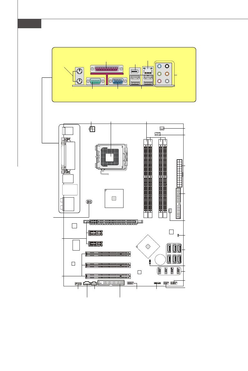
M S-7360 M ainboard Mainboard Layout CPUFAN1 Top : mouse Bottom: keyboard JPW1 Top : Parallel Port Bottom: COM portA VGA port (optional) Top:1394 (optional ) Bottom: USB ports Int el P35/ G33 Top: LAN Jack Bottom: USB ports Line-In Line-Out T:RS-Out M:CS- Ou t…
-
Page 14: Packing Checklist
Getting Started Packing Checklist Standard Cable for MSI Driver/Utility CD IDE Devices (Optional) MSI motherboard USB Bracket (Optional) SATA Cable Power Cable Back IO Shield 1394 Bracket (Optional) User’s Guide * The pictures are for reference only and may vary from the packing contents of the…
-
Page 15: Chapter 2 Hardware Setup
Hardware Setup Chapter 2 Hardware Setup This chapter provides you with the information about hardware setup procedures. While doing the installation, be careful in holding the components and follow the installation procedures. For some components, if you install in the wrong orientation, the components will not work properly.
-
Page 16: Quick Components Guide
M S-7360 M ainboard Quick Components Guide SYSFAN2, CPU, p.2-3 DDRII DIMMs, p.2-7 p.2-14 JPW1, p.2-9 CPUFAN1, p.2-14 Back Panel I/O, p.2-10 IDE1, p.2-12 JPWR3, p.2-9 PCI Express slots, p.2-20 SYSFAN1, p.2-14 JBAT1, SATA1~7, p.2-19 p.2-13 CD_IN1, JUSB1~4, p.2-14 p.2-16 PCI Slots, p.2-20 JFP1, p.2-18…
-
Page 17: Cpu (Central Processing Unit)
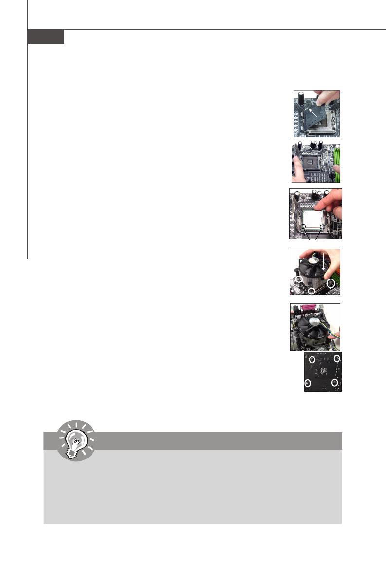
Celeron processor in LGA 775 package. When you are installing the CPU, make sure to install the cooler to prevent overheating. If you do not have the CPU cooler, consult your dealer before turning on the computer. For the latest information about CPU, please visit http://www.msi.com.tw/testreport.htm Important Overheating Overheating will seriously damage the CPU and system.
-
Page 18: Cpu & Cooler Installation
M S-7360 M ainboard CPU & Cooler Installation W hen you are installing the CPU, make sure the CPU has a cooler attached on the top to prevent overheating. Meanwhile, do not forget to apply some thermal paste on CPU before installing the heat sink/cooler fan for better heat dispersion. Follow the steps below to install the CPU &…
-
Page 19
Hardware Setup 5. Lift the load lever up and open the 6. After confirming the CPU direction load plate. for correct mating, put down the CPU in the socket housing frame. Be sure to grasp on the edge of the CPU base. Note that the align- ment keys are matched. -
Page 20
M S-7360 M ainboard 9. Press down the load lever lightly 10. Align the holes on the mainboard onto the load plate, and then se- with the heatsink. Push down the cure the lever with the hook under c ooler u nti l i ts f ou r c lip s g et retention tab. -
Page 21: Memory
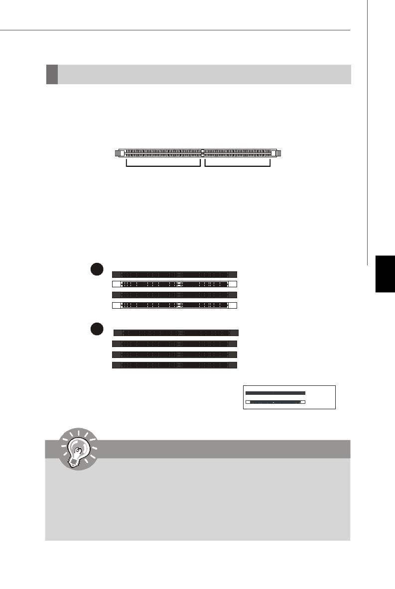
Hardware Setup Memory These DIMM slots are used for installing memory modules. For more information on compatible components, please visit http://www.msi.com. tw/testreport.htm DDR2 240-pin, 1.8V 56×2=112 pin 64×2=128 pin Dual-Channel mode Population Rule In Dual-Channel mode, the memory modules can transmit and receive data with two data bus lines simultaneously.
-
Page 22: Installing Memory Modules
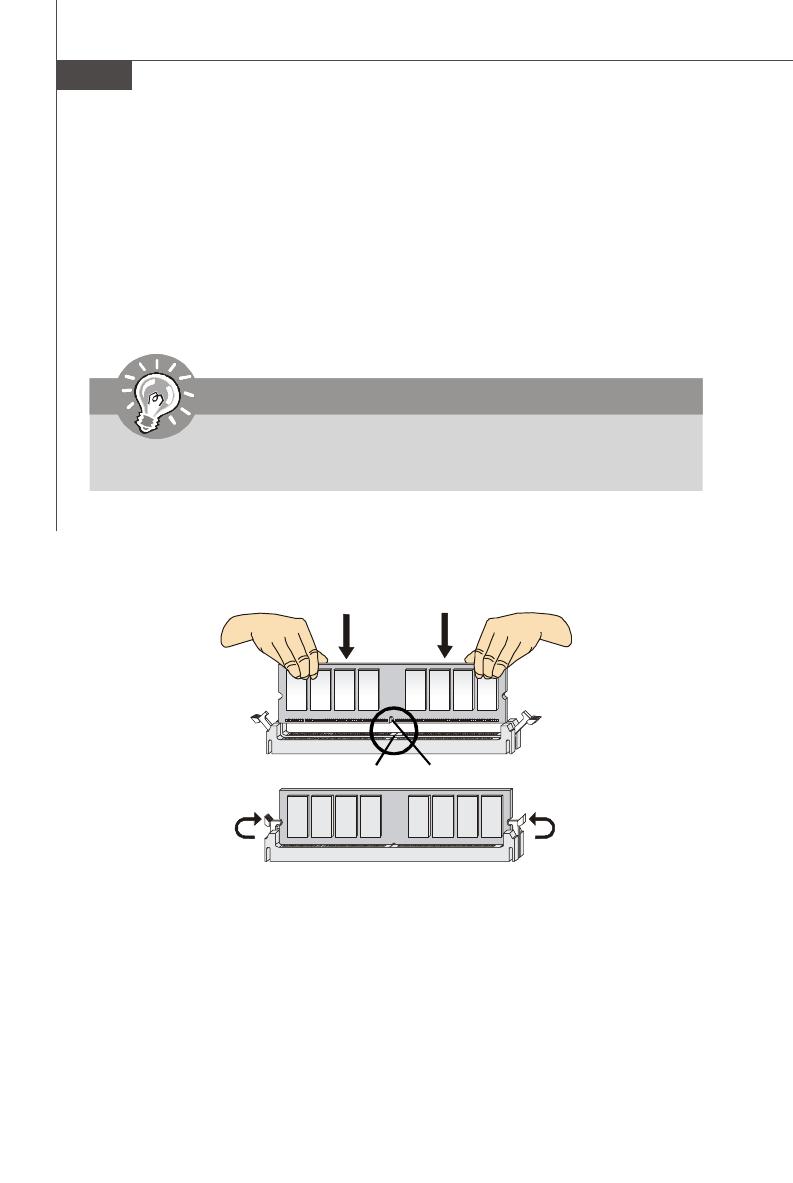
M S-7360 M ainboard Installing Memory Modules 1. The memory module has only one notch on the center and will only fit in the right orientation. 2. Insert the memory module vertically into the DIMM slot. Then push it in until the golden finger on the memory module is deeply inserted in the DIMM slot.
-
Page 23: Power Supply
Hardware Setup Power Supply ATX 24-Pin Power Connector: JPWR3 This connector allows you to connect an ATX 24-pin power supply. pin 13 To connect the ATX 24-pin power supply, make sure the plug of the power supply is inserted in the proper orientation and the pins are aligned.
-
Page 24: Back Panel
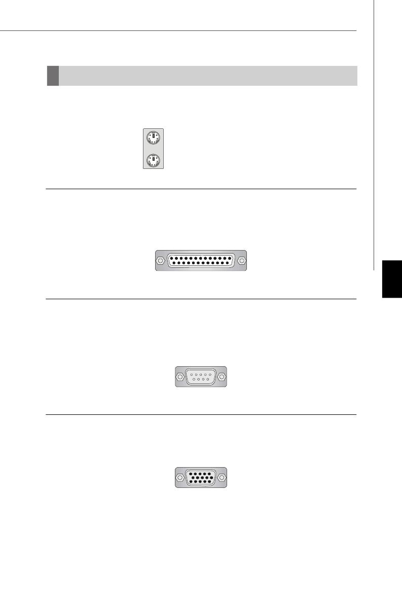
M S-7360 M ainboard Back Panel Parallel Port (optional) Mouse 1394 Port Line-In RS-Out Line-Out CS-Out SS-Out USB Ports Keyboard VGA Port Serial Port (optional) M ouse/Keyboard Connector ® ® The standard PS/2 mouse/keyboard DIN connector is for a PS/2 mouse/keyboard.
-
Page 25
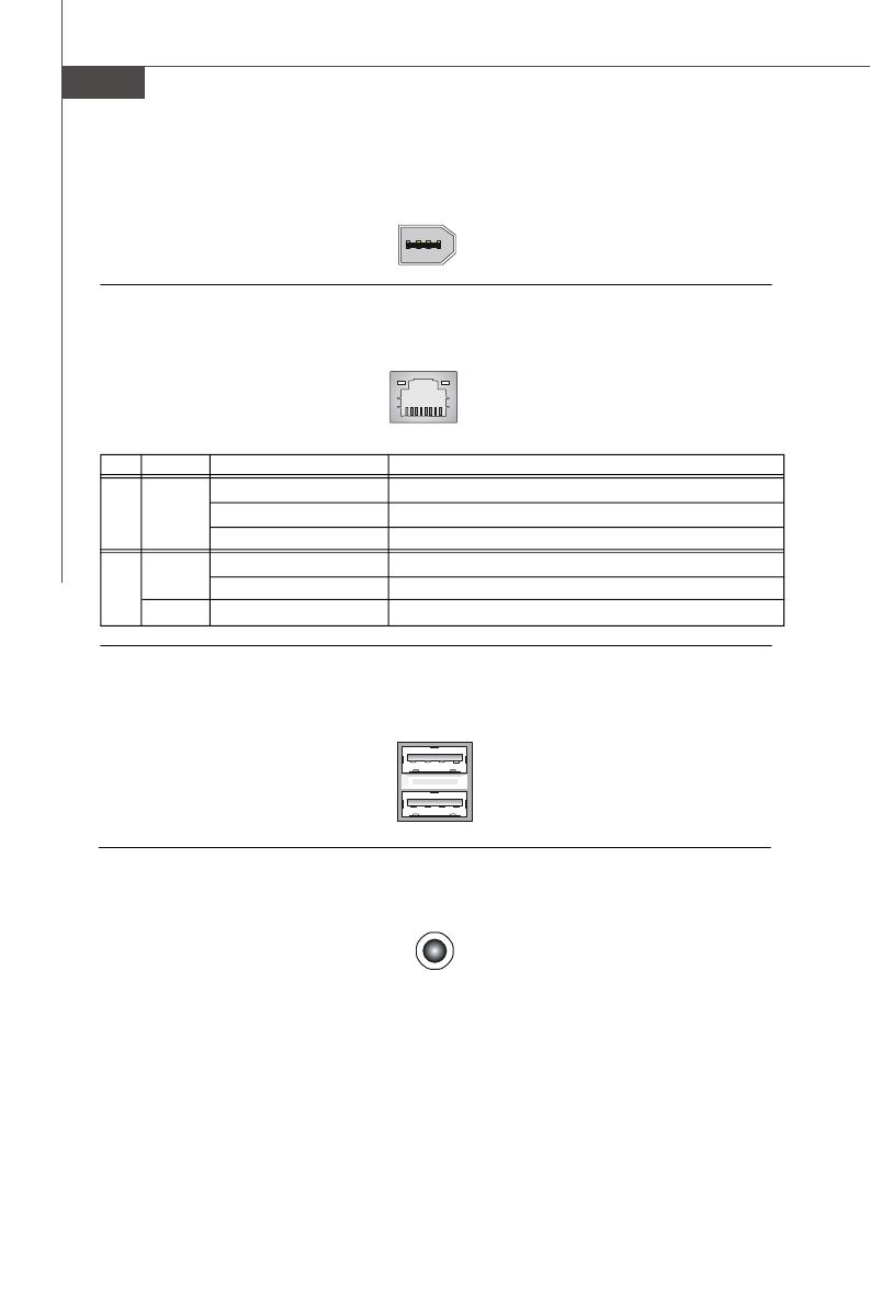
Hardware Setup LAN (RJ-45) Jack The standard RJ-45 jack is for connection Activity Indicator Link Indicator to single Local Area Network (LAN). You can connect a network cable to it. Color LED State condition LAN link is not established. Left Orange On (steady state) LAN link is established. -
Page 26: Connectors
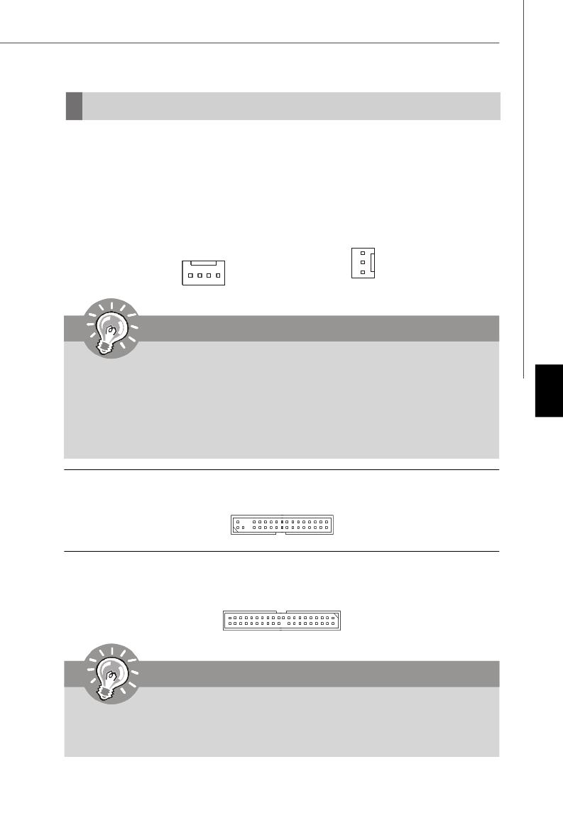
M S-7360 M ainboard Connectors Floppy Disk Drive Connector: FDD1 This connector supports 360KB, 720KB, 1.2MB, 1.44MB or 2.88MB floppy disk drive. FDD1 IDE Connector: IDE1 This connector supports IDE hard disk drives, optical disk drives and other IDE devices. IDE1 Important If you install two IDE devices on the same cable, you must configure the…
-
Page 27
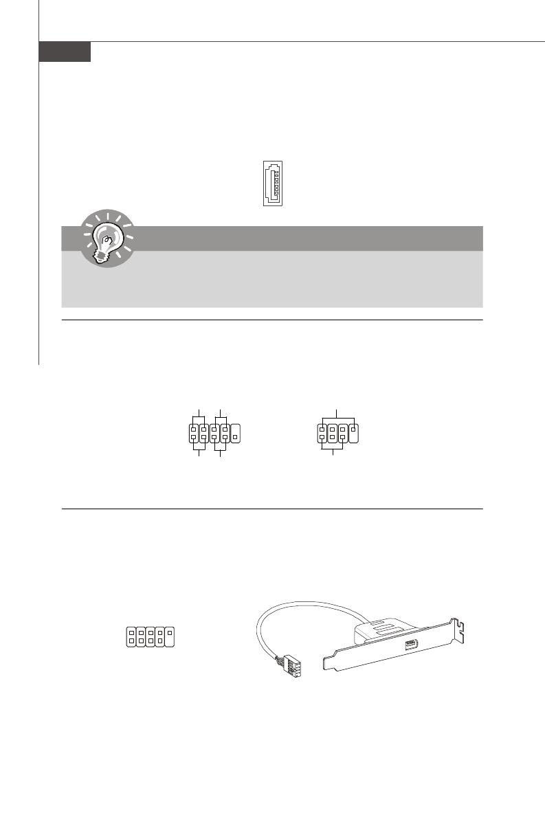
Hardware Setup Serial ATA Connector: SATA1/ SATA2/ SATA3/ SATA4/ SATA5/ SATA6/ SATA7 (SATA5 & SATA6 are for ICH9R only, SATA7 is con- trolled by Marvell 88SE6111) This connector is a high-speed Serial ATA interface port. Each connector can con- nect to one Serial ATA device. SATA7 (optional) SATA6… -
Page 28
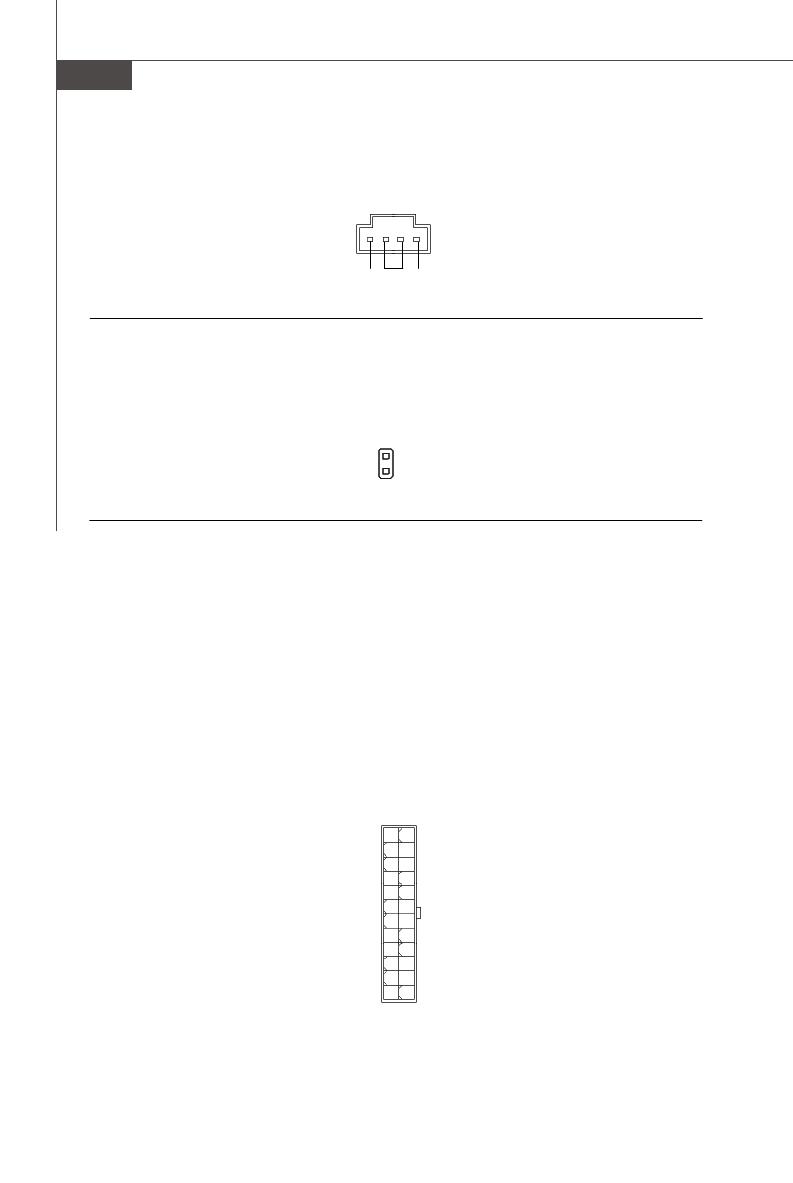
M S-7360 M ainboard Fan Power Connectors: CPUFAN1, SYSFAN1, SYSFAN2 The fan power connectors support system cooling fan with +12V. W hen connecting the wire to the connectors, always note that the red wire is the positive and should be connected to the +12V; the black wire is Ground and should be connected to GND. If the mainboard has a System Hardware Monitor chipset on-board, you must use a specially designed fan with speed sensor to take advantage of the CPU fan control. -
Page 29
Hardware Setup Front Panel Audio Connector: JAUD1 This connector allows you to connect the front panel audio and is compliant with ® Intel Front Panel I/O Connectivity Design Guide. JAUD1 HD Audio Pin Definition SIGNAL DESCRIPTION MIC_L Microphone — Left channel Ground MIC_R Microphone — Right channel… -
Page 30
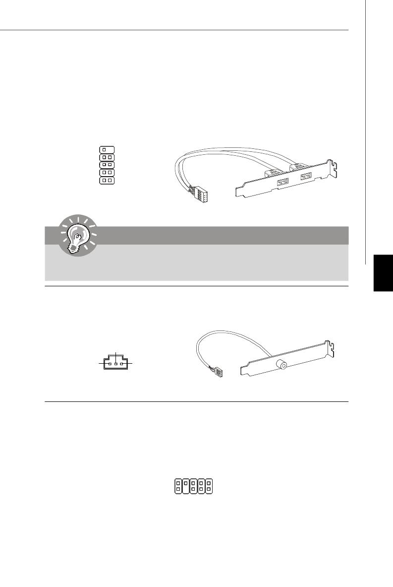
M S-7360 M ainboard Front USB Connector: JUSB1 / JUSB2 / JUSB3 / JUSB4 ® This connector, compliant with Intel I/O Connectivity Design Guide, is ideal for con- necting high-speed USB interface peripherals such as USB HDD, digital cameras, M P3 players, printers, modems and the like. Pin Definition SIGNAL SIGNAL… -
Page 31
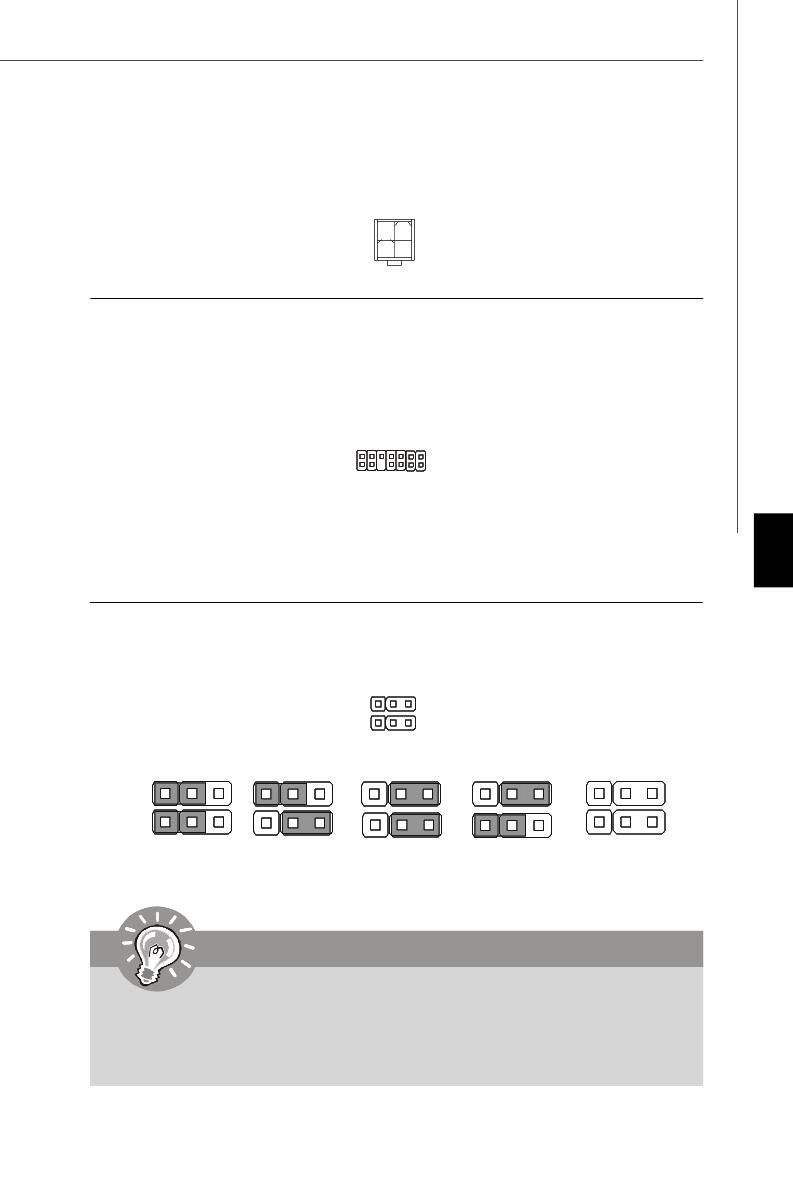
Hardware Setup S/PDIF-Out Connector: JSPD1 (Optional) This connector is used to connect S/PDIF (Sony & Philips Digital Interconnect Format) interface for digital audio transmission. SPDIF-out JSPD1 S/PDIF Bracket (Optional) IEEE1394 Connector: J1394_1 (Optional) This connector allows you to connect the IEEE1394 device via an optional IEEE1394 bracket. -
Page 32: Front Panel Connectors: Jfp1, Jfp2
M S-7360 M ainboard Front Panel Connectors: JFP1, JFP2 These connectors are for electrical connection to the front panel switches and LEDs. ® The JFP1 is compliant with Intel Front Panel I/O Connectivity Design Guide. Power Power Switch JFP1 Reset Switch JFP1 Pin Definition SIGNAL…
-
Page 33: Jumper
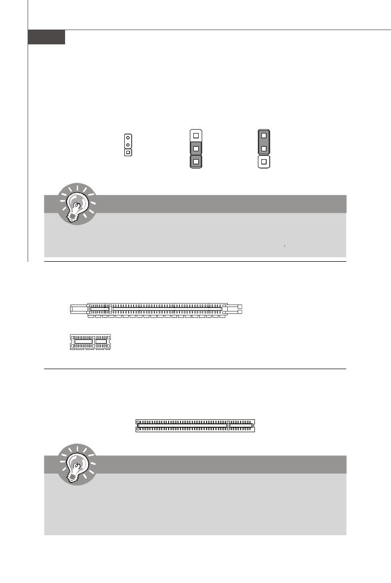
Hardware Setup Jumpers Clear CMOS Jumper: JBAT1 There is a CMOS RAM onboard that has a power supply from an external battery to keep the data of system configuration. W ith the CMOS RAM, the system can auto- matically boot OS every time it is turned on. If you want to clear the system configuration, set the jumper to clear data.
-
Page 34: Slots
M S-7360 M ainboard Slots PCI (Peripheral Component Interconnect) Express Slot The PCI Express slot supports the PCI Express interface expansion card. The PCI Express x 16 supports up to 4.0 GB/s transfer rate. The PCI Express x 8 supports up to 2.0 GB/s transfer rate. The PCI Express x 4 supports up to 1.0 GB/s transfer rate.
-
Page 35: Chapter 3 Bios Setup
BIOS Setup Chapter 3 BIOS Setup This chapter provides information on the BIOS Setup program and allows you to configure the system for optimum use. You may need to run the Setup program when: ² An error message appears on the screen during the system booting up, and requests you to run SETUP.
-
Page 36: Entering Setup
M S-7360 M ainboard Entering Setup Power on the computer and the system will start POST (Power On Self Test) process. W hen the message below appears on the screen, press <DEL> key to enter Setup. Press DEL to enter SETUP If the message disappears before you respond and you still wish to enter Setup, restart the system by turning it OFF and On or pressing the RESET button.
-
Page 37: Control Keys
BIOS Setup Control Keys < ↑> Move to the previous item < ↓> Move to the next item < ←> Move to the item in the left hand < →> Move to the item in the right hand <Enter> Select the item <Esc>…
-
Page 38: The Main Menu
M S-7360 M ainboard The Main Menu Standard CM OS Features Use this menu for basic system configurations, such as time, date etc. Advanced BIOS Features ® Use this menu to setup the items of AMI special enhanced features. Integrated Peripherals Use this menu to specify your settings for integrated peripherals.
-
Page 39
BIOS Setup Load Optimized Defaults Use this menu to load the default values set by the mainboard manufacturer specifi- cally for optimal performance of the mainboard. BIOS Setting Password Use this menu to set the password for BIOS. Save & Exit Setup Save changes to CMOS and exit setup. -
Page 40: Standard Cmos Features
M S-7360 M ainboard Standard CMOS Features The items in Standard CMOS Features Menu includes some basic setup items. Use the arrow keys to highlight the item and then use the <PgUp> or <PgDn> keys to select the value you want in each item. Date (MM:DD:YY) This allows you to set the system to the date that you want (usually the current date).
-
Page 41
BIOS Setup LBA/Large M ode This allows you to enable or disable the LBA Mode. Setting to Auto enables LBA mode if the device supports it and the devices is not already formatted with LBA mode disabled. DM A M ode Select DMA Mode. -
Page 42: Advanced Bios Features
M S-7360 M ainboard Advanced BIOS Features Boot Sector Protection This function protects the BIOS from accidental corruption by unauthorized users or computer viruses. W hen enabled, the BIOS’ data cannot be changed when attempt- ing to update the BIOS with a Flash utility. To successfully update the BIOS, you’ll need to disable this Flash BIOS Protection function.
-
Page 43
BIOS Setup IOAPIC Function This field is used to enable or disable the APIC (Advanced Programmable Interrupt Controller). Due to compliance with PC2001 design guide, the system is able to run in APIC mode. Enabling APIC mode will expand available IRQ resources for the system. MPS Table Version This field allows you to select which MPS (Multi-Processor Specification) version to be used for the operating system. -
Page 44
M S-7360 M ainboard Boot Sequence Press <Enter> to enter the sub-menu and the following screen appears: 1st/ 2nd/ 3rd Boot Device The items allow you to set the first/ second/ third boot device where BIOS attempts to load the disk operating system. Boot From Other Device Setting the option to [Yes] allows the system to try to boot from other device. -
Page 45: Integrated Peripherals
BIOS Setup Integrated Peripherals USB Controller This setting allows you to enable/disable the onboard USB controller. USB Device Legacy Support Select [Enabled] if you need to use a USB-interfaced device in the operating system. Onboard LAN Controller This item is used to enable/disable the onboard LAN controller. LAN Option ROM This item is used to decide whether to invoke the Boot ROM of the LAN controller.
-
Page 46
M S-7360 M ainboard On-Chip ATA Devices Press <Enter> to enter the sub-menu and the following screen appears: PCI IDE BusMaster This item allows you to enable/ disable BIOS to used PCI busmastering for reading/ writing to IDE drives. On-Chip SATA Controller This setting is used to specify the operating mode for SATA devices. -
Page 47: Power Management Setup
BIOS Setup Power Management Setup Important S3-related functions described in this section are available only when your BIOS supports S3 sleep mode. ACPI Function This item is to activate the ACPI (Advanced Configuration and Power Management Interface) Function. If your operating system is ACPI-aware, such as W indows 2000/ XP, select [Enabled].
-
Page 48
M S-7360 M ainboard Re-Call VGA BIOS From S3 W hen ACPI Standby State is set to [S3], users can select the options in this field. Selecting [Enabled] allows BIOS to call VGABIOS to initialize the VGA card when system wakes up (resumes) from S3 sleep state. The system resume time is short- ened when you disable the function, but system will need an VGA driver to initialize the VGA card. -
Page 49
BIOS Setup Resume From S3 by PS/2 Mouse This setting determines whether the system will be awakened from what power saving modes when input signal of the PS/2 mouse is detected. Resume by PCI Device (PME#) W hen set to [Enabled], the feature allows your system to be awakened from the power saving modes through any event on PME (Power Management Event). -
Page 50: Pnp/Pci Configurations
M S-7360 M ainboard PNP/PCI Configurations This section describes configuring the PCI bus system and PnP (Plug & Play) feature. PCI, or Peripheral Component Interconnect, is a system which allows I/O devices to operate at speeds nearing the speed the CPU itself uses when communicating with its special components.
-
Page 51
BIOS Setup IRQ Resource Setup Press <Enter> to enter the sub-menu and the following screen appears. IRQ 3/4/5/7/9/10/11/14/15 These items specify the bus where the specified IRQ line is used. The settings determine if AMIBIOS should remove an IRQ from the pool of avail- able IRQs passed to devices that are configurable by the system BIOS. -
Page 52: H/W Monitor
M S-7360 M ainboard H/W Monitor Chassis Intrusion The field enables or disables the feature of recording the chassis intrusion status and issuing a warning message if the chassis is once opened. To clear the warning message, set the field to [Reset]. The setting of the field will automatically return to [Enabled] later.
-
Page 53: Frequency/Voltage Control
D.O.T Control D.O.T. (Dynamic Overclocking Technology) is the automatic overclocking function, ’s newly developed CoreCell included in the MSI Technology. It is designed to detect the load balance of CPU while running programs, and to adjust the best CPU frequency automatically. W hen the motherboard detects CPU is running programs, it will speed up CPU automatically to make the program run smoothly and faster.
-
Page 54
M S-7360 M ainboard [Sergeant] 2nd level of overclocking, increasing the frequency by 3%. [Captain] 3rd level of overclocking, increasing the frequency by 5%. [Colonel] 4th level of overclocking, increasing the frequency by 7%. [General] 5th level of overclocking, increasing the frequency by 10%. [Commander] 6th level of overclocking, increasing the frequency by 15%. -
Page 55
BIOS Setup DRAM RAS# to CAS# Delay This field allows you to set the number of cycles for a timing delay between the CAS and RAS strobe signals, used when DRAM is written to, read from or refreshed. Fast speed offers faster performance while slow speed offers more stable performance. -
Page 56
M S-7360 M ainboard VTT FSB Voltage This item allows you to set the FSB VTT voltage. Spread Spectrum Configuration CPU Spread Spectrum This setting is used to enable or disable the Spread Spectrum feature. W hen overclocking, always set it to [Disabled]. Important 1. -
Page 57: Load Fail-Safe/ Optimized Defaults
BIOS Setup Load Fail-Safe/ Optimized Defaults The two options on the main menu allow users to restore all of the BIOS settings to the default Fail-Safe or Optimized values. The Optimized Defaults are the default values set by the mainboard manufacturer specifically for optimal performance of the mainboard.
-
Page 58: Bios Setting Password
M S-7360 M ainboard BIOS Setting Password W hen you select this function, a message as below will appear on the screen: Type the password, up to six characters in length, and press <Enter>. The password typed now will replace any previously set password from CMOS memory. You will be prompted to confirm the password.
-
Page 59: Appendix A Dual Core Center
Dual Core Center Dual CoreCenter, the most useful and powerful utility that MSI has spent muc h researc h and ef forts to develop, helps users to monitor or configure the hard- ware status of MSI Mainboard & MSI Graphics card in windows, such as CPU/GPU clock, voltage, fan speed and temperature.
-
Page 60: Activating Dual Core Center
Activating Dual Core Center Once you have your Dual Core Center installed (locate the setup source file in the setup CD accompanying with your mainboard, path: Utility —> MSI Utility —> Dual Core Center), it will have an icon in the system tray, a short cut icon on the desktop, and a short cut path in your “Start-up”…
-
Page 61: Main
Dual Core Center Main Before using this utility, we have to remind you: only when installing the MSI V044 (V044 has to install with the version 8.26 or newer driver)/ V046 or V060 graphics card can activate the full function of this utility. If you install a graphics card of other brand, only hardware status of the MSI mainboard would be available.
-
Page 62
M S-7360 M ainboard AV/ Game/ Office/ Silence/ Cool MSI provides five common settings for different environments. The settings had been set to optimal values to reac h better performanc e in eac h environment. Click the button you need. -
Page 63: Dot(Dynamic Over Clocking
Dynamic Overclocking Technology is an automatic overclocking function, included in ’s newly developed Dual CoreCenter Technology. It is designed to detect the the MSI loading of CPU/ GPU while running programs, and to over-clock automatically. When the motherboard detects that the loading of CPU is exceed the default threshold for a time, it will speed up the CPU and fan automatically to make the system run smoother and faster.
-
Page 64: Clock
M S-7360 M ainboard Clock In the Clock sub-menu, you can see clock status (including FSB/ CPU clock of mainboard and GPU/ memory clock of graphics card) of your system. And you can select desired value for overclocking. There will be several items for you to select for overclocking after you click button.
-
Page 65: Voltage
Dual Core Center Voltage In the Voltage sub-menu, you can see voltage status (including Vcore, memory, GPU voltage… etc.) of your system, and you can select desired value for overclocking. It will show several items to select for overclocking after you click the button.
-
Page 66: Fan Speed
M S-7360 M ainboard FAN Speed In the FAN Speed sub-menu, you can read fan status of your system. Select higher speed for better cooling effect. There are several sections for you to change the fan speed to a section after clicking button.
-
Page 67: Temperature
Dual Core Center Temperature In the Temperature sub-menu, you can see temperature status of your system. On the underside, it shows the graphs of the temperatures. Only the curves of the item which the button is lit up with red color will be shown.
-
Page 68: User Profile
M S-7360 M ainboard User Profile In the User Profile sub-menu, click the setting button that besides the user profile bar, and the next screen will appear. Here you can define the clock/ fan speed/ voltage by your need, click the button to choose a value quickly, or click the plus / minus sign button to…
-
Page 69
Dual Core Center Use the draw bar to set the max system temperature. W hen the system temperature exceeds the threshold you defined, the system will pop up a warning message and shut down the system. Use the draw bar to set the minimal fan speed. When the fan speed is lower than the threshold you defined, the system will pop up a warning message. -
Page 70: Appendix B Realtek Alc888 Audio
Realtek ALC888 Audio Appendix B Realtek ALC888 Audio The Realtek ALC888 provides 10-channel DAC that si- multaneously supports 7.1 sound playback and 2 chan- nels of independent s tereo s ound output (multiple streaming) through the Front-Out-Left and Front-Out- Right channels.
-
Page 71: Installing The Realtek Hd Audio Driver
M S-7360 M ainboard Installing the Realtek HD Audio Driver You need to install the driver for Realtek ALC888 codec to function properly before you can get access to 2-, 4-, 6-, 8- channel or 7.1+2 channel audio operations. Follow the procedures described below to install the drivers for different operating systems.
-
Page 72
Realtek ALC888 Audio 3. Click Next to install the Realtek High Definition Audio Driver. Click here 4. Click Finish to restart the system. S el ec t t hi s option Click here… -
Page 73: Software Configuration
M S-7360 M ainboard Software Configuration After installing the audio driver, you are able to use the 2-, 4-, 6- or 8- channel audio feature now. Click the audio icon from the system tray at the lower-right corner of the screen to activate the HD Audio Configuration. It is also available to enable the audio driver by clicking the Azalia HD Sound Effect M anager from the Control Panel.
-
Page 74: Sound Effect
Realtek ALC888 Audio Sound Effect Here you can select a sound effect you like from the Environment list. Environment Simulation You will be able to enjoy different sound experience by pulling down the arrow, totally 23 kinds of sound effect will be shown for selection. Realtek HD Audio Sound Manager also provides five popular settings “Stone Corridor”, “Bathroom”, “Sewer pipe”, “Arena”…
-
Page 75
M S-7360 M ainboard Equalizer Selection Equalizer frees users from default settings; users may create their owned preferred settings by utilizing this tool. 10 bands of equalizer, ranging from 100Hz to 16KHz. Save Reset The settings are saved 10 bands of equalizer permanently for future would go back to the de- fault setting… -
Page 76
Realtek ALC888 Audio Frequently Used Equalizer Setting Realtek recognizes the needs that you might have. By leveraging our long experience at audio field, Realtek HD Audio Sound Manager provides you certain optimized equal- izer settings that are frequently used for your quick enjoyment. [How to Use It] Other than the buttons “Pop”… -
Page 77
M S-7360 M ainboard Mixer In the Mixer part, you may adjust the volumes of the rear and front panels individually. 1. Adjust Volume You can adjust the volume of the speakers that you pluged in front or rear panel. Important Before set up, please make sure the playback devices are well plugged in the jacks on the rear or front panel. -
Page 78
Realtek ALC888 Audio W hen you are playing the first audio source (for example: use W indows Media Player to play DVD/VCD), the output will be played from the rear panel, which is the default setting. Then you must to select the Realtek HD Audio 2nd output from the scroll list first, and use a different program to play the second audio source (for example: use Winamp to play MP3 files). -
Page 79
M S-7360 M ainboard 3. Playback control Playback device Tool Mute This function is to let you freely decide which ports to output the sound. And this is essential when multi- streaming playback enabled. — Realtek HD Audio Output — Realtek HD Audio 2nd Output M u te You may choose to mute single or multiple volume controls or to completely mute sound output. -
Page 80
Realtek ALC888 Audio 4. Recording control Recording device -Realtek HDA Primary input Tool Mute -Mic in at front panel (Green) M u te You may choose to mute single or multiple volume controls or to completely mute sound input. Tool — Show the following volume controls This is to let you freely decide which volume control items to be displayed. -
Page 81
M S-7360 M ainboard Audio I/O In this tab, you can easily configure your multi-channel audio function and speakers. You can choose a desired multi-channel operation here. a. Headphone for the common headphone b. 2CH Speaker for Stereo-Speaker Output c. 4CH Speaker for 4-Speaker Output d. -
Page 82
Realtek ALC888 Audio Connector Settings Click to access connector settings. Disable front panel jack detection (option) Jack detection function only works with HD audio front panel. M ute rear panel output when front headphone plugged in. Enable auto popup dialogue, when device has been plugged in Once this item checked, the dialog “Connected device”… -
Page 83
M S-7360 M ainboard S/PDIF (optional, for HDMI graphics card only) Short for Sony/Philips Digital Interface, a standard audio file transfer format. S/PDIF allows the transfer of digital audio signals from one device to another without having to be converted first to an analog format. Maintaining the viability of a digital signal prevents the quality of the signal from degrading when it is converted to analog. -
Page 84
Realtek ALC888 Audio Test Speakers You can select the speaker by clicking it to test its functionality. The one you select will light up and make testing sound. If any speaker fails to make sound, then check whether the cable is inserted firmly to the connector or replace the bad speakers with good ones. -
Page 85
M S-7360 M ainboard Microphone In this tab you may set the function of the microphone. Select the Noise Suppres- sion to remove the possible noise during recording, or select Acoustic Echo Cancelltion to cancel the acoustic echo druing recording. Acoustic Echo Cancelltion prevents playback sound from being recorded by mi- crophone together with your sound. -
Page 86: D Audio Demo
Realtek ALC888 Audio 3D Audio Demo In this tab you may adjust your 3D positional audio before playing 3D audio applica- tions like gaming. You may also select different environment to choose the most suitable environment you like. B-17…
-
Page 87
M S-7360 M ainboard Information In this tab it provides some information about this HD Audio Configuration utility, including Audio Driver Version, DirectX Version, Audio Controller & Audio Codec. You may also select the language of this utility by choosing from the Language list. Also there is a selection Show icon in system tray. -
Page 88: Hardware Setup
Realtek ALC888 Audio Hardware Setup Connecting the Speakers W hen you have set the Multi-Channel Audio Function mode properly in the software utility, connect your speakers to the correct phone jacks in accordance with the setting in software utility. n 2-Channel M ode for Stereo-Speaker Output Refer to the following diagram and caption for the function of each phone jack on the back panel when 2-Channel Mode is selected.
-
Page 89
M S-7360 M ainboard n 4-Channel M ode for 4-Speaker Output 4-Channel Analog Audio Output Line In Line Out (Front channels) Line Out (Rear channels) No function No function B-20… -
Page 90
Realtek ALC888 Audio n 6-Channel M ode for 6-Speaker Output 6-Channel Analog Audio Output Line In Line Out (Front channels) Line Out (Rear channels) Line Out (Center and Subwoofer channel) No function B-21… -
Page 91
M S-7360 M ainboard n 8-Channel M ode for 8-Speaker Output 8-Channel Analog Audio Output Line In Line Out (Front channels) Line Out (Rear channels) Line Out (Center and Subwoofer channel) Line Out (Side channels) B-22…
В представленном списке руководства для конкретной модели Материнской платы — MSI P35 Neo. Вы можете скачать инструкции к себе на компьютер или просмотреть онлайн на страницах сайта бесплатно или распечатать.
- Инструкции и файлы
- Характеристики
- Основные поломки
- Сервисы по ремонту
В случае если инструкция на русском не полная или нужна дополнительная информация по этому устройству, если вам нужны
дополнительные файлы: драйвера, дополнительное руководство пользователя (производители зачастую для каждого
продукта делают несколько различных документов технической помощи и руководств), свежая версия прошивки, то
вы можете задать вопрос администраторам или всем пользователям сайта, все постараются оперативно отреагировать
на ваш запрос и как можно быстрее помочь. Ваше устройство имеет характеристики:Socket: LGA775, Поддерживаемые процессоры: Intel Core 2 Extreme/Core 2 Quad/Core 2 Duo/Pentium Dual-Core/Pentium Extreme/Pentium D/Pentium 4 Extreme/Pentium 4/Celeron 4xx series/Celeron D/Celeron Dual-Core/Wolfdale/Yorkfield, Системная шина: 800 МГц — 1333 МГц, Поддержка Hyper-Threading: есть, Поддержка многоядерных процессоров: есть, Чипсет: Intel P35, полные характеристики смотрите в следующей вкладке.
Для многих товаров, для работы с MSI P35 Neo могут понадобиться различные дополнительные файлы: драйвера, патчи, обновления, программы установки. Вы можете скачать онлайн эти файлы для конкретнй модели MSI P35 Neo или добавить свои для бесплатного скачивания другим посетителями.
Если вы не нашли файлов и документов для этой модели то можете посмотреть интсрукции для похожих товаров и моделей, так как они зачастую отличаются небольшим изменениями и взаимодополняемы.
Обязательно напишите несколько слов о преобретенном вами товаре, чтобы каждый мог ознакомиться с вашим отзывом или вопросом. Проявляйте активность что как можно бльше людей смогли узнать мнение настоящих людей которые уже пользовались MSI P35 Neo.
Основные и самые важные характеристики модели собраны из надежных источников и по характеристикам можно найти похожие модели.
| Процессор | |
| Socket | LGA775 |
| Поддерживаемые процессоры | Intel Core 2 Extreme/Core 2 Quad/Core 2 Duo/Pentium Dual-Core/Pentium Extreme/Pentium D/Pentium 4 Extreme/Pentium 4/Celeron 4xx series/Celeron D/Celeron Dual-Core/Wolfdale/Yorkfield |
| Системная шина | 800 МГц — 1333 МГц |
| Поддержка Hyper-Threading | есть |
| Поддержка многоядерных процессоров | есть |
| Чипсет | |
| Чипсет | Intel P35 |
| BIOS | AMI |
| Поддержка SLI/CrossFire | нет |
| Память | |
| Память | DDR2 DIMM, 667 — 800 МГц |
| Количество слотов памяти | 4 |
| Поддержка двухканального режима | есть |
| Максимальный объем памяти | 8 Гб |
| Дисковые контроллеры | |
| IDE | количество слотов: 1, UltraDMA 133 |
| SATA | количество разъемов SATA 3Gb/s: 5, RAID: нет |
| Слоты расширения | |
| Слоты расширения | 1xPCI-E x16, 3xPCI-E x1, 2xPCI |
| Аудио/видео | |
| Звук | 7.1CH, HDA, на основе Realtek AL888 |
| Сеть | |
| Ethernet | 1000 Мбит/с, на основе Realtek 8111B |
| Подключение | |
| Наличие интерфейсов | 12 USB, выход S/PDIF, 1xCOM, Ethernet, PS/2 (клавиатура), PS/2 (мышь), LPT |
| Разъемы на задней панели | 4 USB, 1xCOM, Ethernet, PS/2 (клавиатура), PS/2 (мышь), LPT |
| Основной разъем питания | 24-pin |
| Разъем питания процессора | 4-pin |
| Дополнительные параметры | |
| Форм-фактор | ATX |
| Комплектация | 1 кабель IDE, 1 кабель SATA, 1 кабель питания SATA |
| Дополнительная информация | Опционально — два порта IEEE1394. |
Здесь представлен список самых частых и распространенных поломок и неисправностей у Материнских плат. Если у вас такая поломка то вам повезло, это типовая неисправность для MSI P35 Neo и вы можете задать вопрос о том как ее устранить и вам быстро ответят или же прочитайте в вопросах и ответах ниже.
| Название поломки | Описание поломки | Действие |
|---|---|---|
| Разрыв Печатных Проводников | ||
| Обрыв Конденсаторов Или Резисторов | ||
| Короткое Замыкание В Электрических Цепях | ||
| Разрушение Разъемов И Слотов | ||
| Поломка Процессорного Разъема | ||
| Выгорание Портов | ||
| Микротрещины В Плате | ||
| Выход Из Строя Сетевого Адаптера | ||
| Перегрев Компонентов | ||
| Не Запускается При Включении | При Включении Не Загружается. В Биос Не Входит. Пост Код — А3 | |
| Какой Компонент | Подскажите Марку Траyзистора Q46? | |
| Не Работает Ps/2 | Сначала Отвалилась Клавиатура, А Через Некоторое Время 6 Коротких Гудков И Не Запускается | |
| Подключить Переднюю Панель | Не Могу Подключить Переднюю Панель | |
| Судя По Всему Отвал Биоса | Материнка Стартует Секунд На 5,Кулер Процессора Берет Обороты И Останавливается.и Так-Циклически,Без Остановок.запуск Невозможен.вечером Либо Завтра Буду Пытаться Его Восстановить,Потом Может Дополню | |
| Пропал Звук На Материнке | Пропал Звук На Материнке, Отображается Только Nvidia Hdmi. Переустановка Драйверов С Офсайта Не Помогла. | |
| Биос | При Старте Звук Через Промежетки Времени Примерно В 1-3 Мин Три Сигнала Потом Стартует Винда , Недавно Вообще Написал Cmos Setting Wrong И C7, Жму Del Меняется На B2 Чтоб Воити В Биос Три Сигнала По Одному Через Промеежутки Времени 1-3 Мин И Черный Экра | |
| Asus M2A-Vm Hdmi | Не Запускается Процессор Phenom Ii X4 945 Rev. C3, На Socket-Ам 3, Нет Даже Сигнала, Черный Экран | |
| Не Включается | После Замены Конденсаторов С34 И С35 Не Включается | |
| Черный Экран | Все Уже Перепробовал И Озу Менял И Переставлял И Ластиком Чистил, И Батарейку Вынимал И Измерял, И Видеокарту С Бп На Заведомо Годную Ставил Исход Один, Черный Экран И Speaker Издает 1 Длинный 2 Коротких, Если Я Не Путаю. | |
| Неправильно Отображается Память | При Установленной Памяти 4 Гигабайта В Биосе Отображается 8. Установил Одну Планку 2 Гига — Отображается 4 | |
В нашей базе сейчас зарегестрированно 18 353 сервиса в 513 города России, Беларусии, Казахстана и Украины.

ЛАСТЕН
⭐
⭐
⭐
⭐
⭐
Адресс:
Марксистская ул., 34 строение 1
Телефон:
74995001412
Сайт:
n/a
Время работы
Круглосуточно
БСМ ТЕХНОЛОДЖИС
⭐
⭐
⭐
⭐
⭐
Адресс:
Волгоградский проспект 28
Телефон:
74956209820
Сайт:
n/a
Время работы
Будни: с 0900 до 1900
Суббота: выходной
Воскресенье: выходной
МАСТЕРСКАЯ РЕМОНТОЗАВР
⭐
⭐
⭐
⭐
⭐
Адресс:
ул.Октябрьская дом 17/18
Телефон:
79653003111
Сайт:
n/a
Время работы
Будни: с 0900 до 1900
Суббота: с 1000 до 1800
Воскресенье: с 1000 до 1800
REMOBI
⭐
⭐
⭐
⭐
⭐
Адресс:
ул. 1-я Останкинская, 55, ТЦ ВДНХ
Телефон:
74993222524
Сайт:
n/a
Время работы
Ежедневно: с 1000 до 2100
REMOBI
⭐
⭐
⭐
⭐
⭐
Адресс:
Каширское ш., 26
Телефон:
74993222524
Сайт:
n/a
Время работы
Ежедневно: с 1000 до 2100
Ремонт материнской платы: (подарок подписчика).
21:27

Очень доволен
хочу
авпваы
Хочу купить
ирлдоьвап ькеьпрлджыкеь дзьакерджь щзрбкежбрь апкыезрбкыеджрбеджр щзапбкерл
Только приобрела,а инструкции нет
Только приобрела,а инструкции нет
Отвалился распрыскиватель
Download
Table of Contents
Add to my manuals
Share
URL of this page:
HTML Link:
Bookmark this page
Manual will be automatically added to «My Manuals»
Print this page
- Manuals
- Brands
- MSI Manuals
- Motherboard
- MS-7360
- User manual
Ms-7360 (v1.x)
Hide thumbs
Also See for MS-7360:
- User manual (91 pages)
1
2
3
4
5
6
7
Table Of Contents
8
9
10
11
12
13
14
15
16
17
18
19
20
21
22
23
24
25
26
27
28
29
30
31
32
33
34
35
36
37
38
39
40
41
42
43
44
45
46
47
48
49
50
51
52
53
54
55
56
57
58
59
60
61
62
63
64
65
66
67
68
69
70
71
72
73
74
75
76
77
78
79
80
81
82
83
84
85
86
87
88
89
90
91
92
93
94
95
96
97
98
99
100
101
102
103
104
105
106
107
108
-
page
of
108/
108 -
Contents
-
Table of Contents
-
Bookmarks
Table of Contents
Advertisement
Available languages
-
EN
-
RU
-
FR
-
DE
Available languages
-
ENGLISH, page 2
-
РУССКИЙ, страница 85
-
FRANÇAIS, page 60
-
DEUTSCH, seite 35
Руководство по установке
P35 Neo/ G33 Neo
Cерии
Руговодство
пользователя
Русский
Ru-1
Table of Contents
Previous Page
Next Page
- 1
- …
- 81
- 82
- 83
- 84
- 85
- 86
- 87
- 88
Show Quick Links
- Quick Links:
-
Specifications
-
Connection Diagram
-
Memory
-
Connectors, Jumpers, Slots
-
Соединители, Перемычки, Разъемы
Hide quick links:
Advertisement
Table of Contents
Related Manuals for MSI MS-7360
-
Motherboard MSi P35 Neo series User Manual
V1.x mainboard (91 pages)
-
Motherboard MSI MS-7365 User Manual
Motherboard (108 pages)
-
Motherboard MSI MS-7364 Instruction Manual
Msi ms-7364 motherboard: instruction manual (91 pages)
-
Motherboard MSI MS-7366 User Manual
Ms-7366 (v1.x) mainboard (108 pages)
-
Motherboard MSI MS-7367 User Manual
K9agm3 series (v1.x) mainboard (95 pages)
-
Motherboard MSi MS-7388 Instruction Manual
V1.x (89 pages)
-
Motherboard MSI MS-7317 Instruction Manual
Msi ms-7317 motherboard: instruction manual (94 pages)
-
Motherboard MSI MS-7320 User Manual
Ms-7320 (v1.x) mainboard (108 pages)


-
Motherboard MSi MS-7320 (V1.X) Manual
V1.x atx mainboard (120 pages)
-
Motherboard MSI MS-7345 User Manual
Ms-7345 (v1.x) mainboard (116 pages)
-
Motherboard MSI MS-7346 User Manual
(v1.x) mainboard (125 pages)
-
Motherboard MSI MS-7353 User Manual
Ms-7353(v1.x) mainboard (116 pages)
-
Motherboard MSi MS-7353 User Manual
Mainboard (128 pages)
-
Motherboard MSI MS-7392 User Manual
Msi ms-7392 motherboard: user guide (108 pages)
-
Motherboard MSI MS-7392 User Manual
Ms-7392 (v2.x) mainboard (117 pages)
-
Motherboard MSI MS-7395 User Manual
Ms-7395 (v1.x) mainboard (108 pages)


Related Content for MSI MS-7360
-
870S-C45 Series Русский
MSI 870S-C45 Series
-
H81M-P32L Русский
MSI H81M-P32L
-
760GM-P25 Русский
MSI 760GM-P25
-
H81M-E34 Series Русский
MSI H81M-E34 Series
-
Wind Board 330 Русский
MSI Wind Board 330
-
870A-G55 Series Русский
MSI 870A-G55 Series
-
760GM-P24 FX Series Русский
MSI 760GM-P24 FX Series
-
MS-7513 Русский
MSI MS-7513


-
760GM-P43 Series Русский
MSI 760GM-P43 Series
-
P45D3Neo3 Series Русский
MSI P45D3Neo3 Series
-
880GMA-E55 Series Русский
MSI 880GMA-E55 Series
-
Z77MA-G43 Series Русский
MSI Z77MA-G43 Series
-
AM1M Series Русский
MSI AM1M Series
-
C847MS-E33 Series Русский
MSI C847MS-E33 Series
-
H61M-E23 (G3) Series Русский
MSI H61M-E23 (G3) Series
-
Z68A-G43 Series Русский
MSI Z68A-G43 Series


This manual is also suitable for:
P35 neo g52-73601×4P35 neo seriesG33 neo series
Table of Contents
20-04-2008
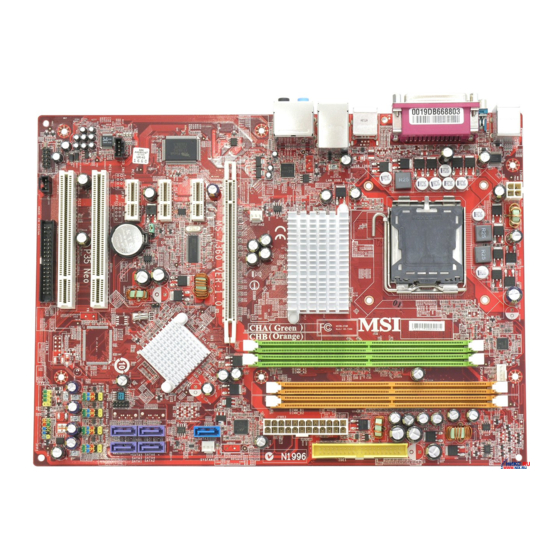
В предыдущем обзоре мы тестировали материнскую плату MSI P35 NEO2-FIR компании Micro-Star International. В этом материале предлагаем взглянуть на еще один более бюджетный вариант, рассчитанный на любителей разгона и производительных систем с современными процессорами – материнскую плату MSI P35 NEO.
Отметим, что в случае, когда на этой плате устанавливается FireWire контроллер к названию модели добавляется индекс F, и ее название выглядит как MSI P35 NEO-F.
Спецификация материнской платы MSI P35 NEO:
|
Производитель |
MSI |
|
Модель |
P35 NEO |
|
Северный мост |
Intel P35 |
|
Южный мост |
Intel ICH9 |
|
Процессорный разъем |
LGA775 |
|
Поддерживаемые процессоры |
Intel Core 2 Quad-Core / Core 2 Duo / Pentium / Celeron Intel Yorkfield, Wolfdale |
|
Системная шина, МГц |
1333/1066/800 МГц |
|
Используемая память |
DDR2 800/667 МГц |
|
Поддержка памяти |
4 x 1,8 В DDR2 DIMM двухканальной архитектуры до 8Гб |
|
Слоты расширения |
1 x PCI-E x16 |
|
Дисковая подсистема |
Южный мост ICH9 поддерживает: Дополнительный контроллер Marvell 88SE6111 поддерживает: |
|
Звуковая подсистема |
Кодек 8-канальнго звука Realtek ALC888 |
|
Поддержка LAN |
Сетевой контроллер RTL 8111B (10/100/1000 Mbit) |
|
Питание |
24-контактный разъем питания ATX |
|
Охлаждение |
Алюминиевые радиаторы на северном и южном мосте |
|
Разъемы для вентиляторов |
1 x CPU |
|
Внешние порты I/O |
2 x PS/2 порта для подключения клавиатуры и мыши |
|
Внутренние порты I/O |
8 x USB |
|
Возможности разгона |
Изменение частоты: FSB , PCI-Express, памяти. |
|
Комплектация |
1 x SATA кабель |
|
Форм-фактор Размеры, мм |
ATX |
|
Сайт производителя |
http://global.msi.com.tw/ Новую версию BIOS для MSI P35 NEO2-FR/FIR можно скачать с официальной страницы. |
Все цены на MSI P35 NEO

Материнская плата MSI P35 NEO упакована в небольшую картонную коробку, оформленную в стиле компании MSI. На упаковке отмечено наличие поддержки 1333 МГц системной шины и 45 нм процессоров.
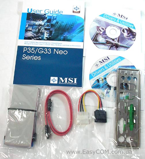
В комплект материнской платы MSI P35 NEO входит:
- два CD-диска с драйверами для Windows Vista и Windows XP;
- руководство пользователя и инструкции по установке,
- шлейф UltraDMA 133/100/66;
- шлейф Serial ATA;
- заглушка панели ввода-вывода;
- переходник питания SATA.
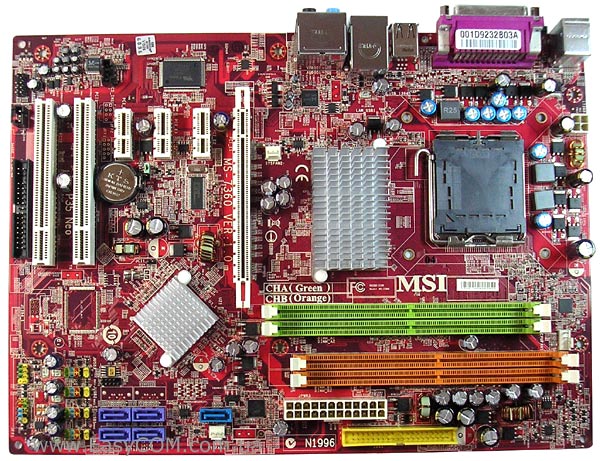
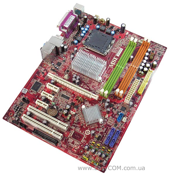
Материнские платы MSI P35 NEO имеют достаточно неплохую компоновку – разъемы питания и порты располагаются в основном по краю текстолита. Хотя есть и недостатки — в не совсем выгодном положении, под слотами PCI, находится FDD разъем, а также открытию защелок зеленых слотов оперативной памяти будет мешать вставленная видеокарта. Проводя модернизацию компьютера, возможно, многие пользователи желали бы иметь три слота PCI вместо двух имеющихся, поэтому этот факт мы тоже отметим как небольшой недостаток MSI P35 NEO. Также не порадовало отсутствие достаточно «модных» в настоящее время полимерных конденсаторов. Стоит заметить, что на подобном PCB компания MSI выпускает модели MSI P35 Neo Combo, которая поддерживает оба типа памяти DDR2 и DDR3, и MSI G33 Neo с интегрированной графикой.
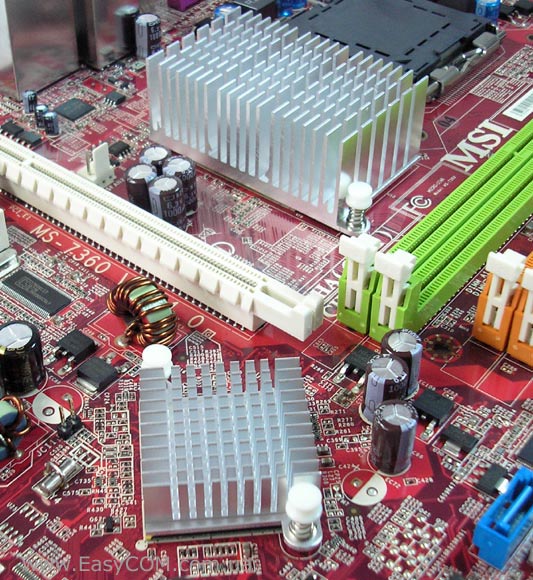
Для охлаждения северного моста используется относительно габаритный, но не очень высокий алюминиевый радиатор. Гораздо меньшие размеры имеет кулер на южном мосте.
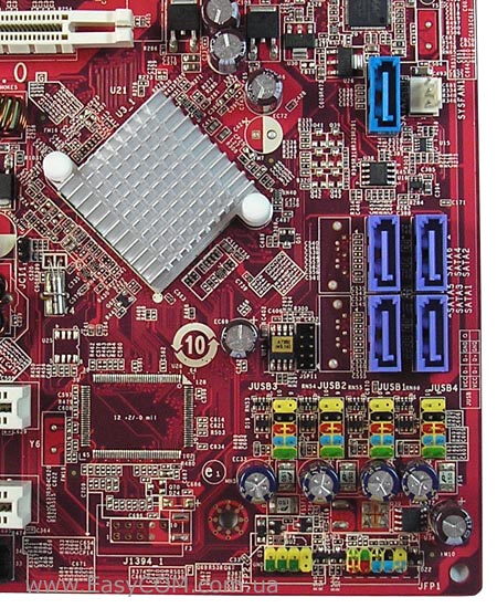
Так как для заполнения PCB материнской платы MSI P35 NEO могут использоваться несколько наборов логики, то на ней видны пустующие места для еще двух разъемов SATA, которые устанавливаются при использовании южного моста Intel ICH9R, а также есть место зарезервированное для контроллера FireWire. В нашем случае на MSI P35 NEO применяется чип Intel ICH9, который поддерживает четыре порта SATA II без возможности создания RAID-массивов. Для обеспечения работы IDE порта и еще одного SATA используется дополнительный контроллер Marvell 88SE6111.
Для удобства подключения, восемь внутренних портов USB и разъем системной панели имеют цветовую маркировку.
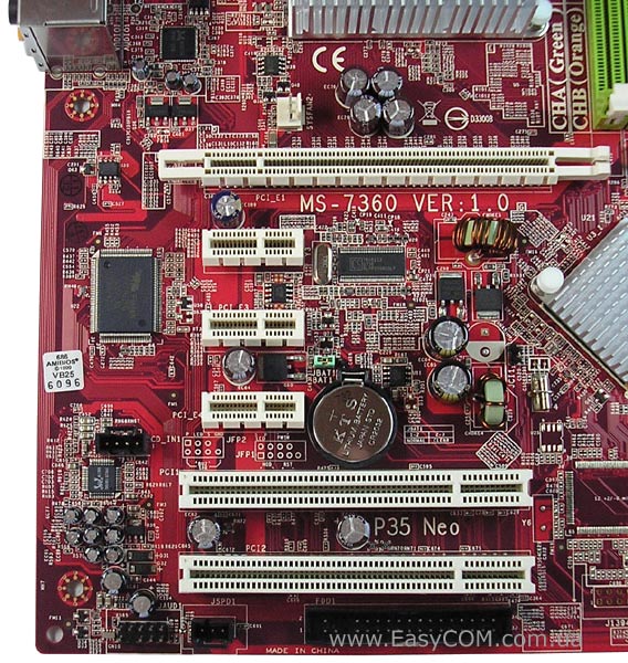
Материнская плата MSI P35 NEO имеет только два слота PCI, три PCIE х1 и один слот PCIE х16. Из интегрированных на плате контроллеров можно отметить гигабитную сетевую карту на RTL 8111B, восьмиканальный звуковой кодек Realtek ALC888, разъем фронт-панели которого поддерживает подключения в HDA и AC`97 форматах.
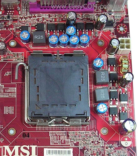
Стабилизатор питания процессора у материнской платы MSI P35 NEO всего лишь трехканальный, но для платы этого класса данный факт и не является чем-то удивительным.
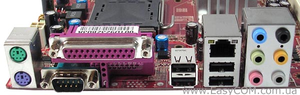
На задней панели выведены следующие порты: два PS/2 для клавиатуры и мыши, четыре разъема USB, COM и LPT порты, разъем RJ45 для сетевых соединений и разъемы для 8-канального звука.
На материнской плате MSI P35 NEO реализованы три разъема для вентиляторов, один из которых 4-контактный для процессорного кулера, а остальные, предназначенные для подключения корпусных вентиляторов, являются 3-контактными. Все разъемы располагаются в разных частях платы, что упрощает выбор места для подключения.
BIOS
В материнской плате MSI P35 NEO используется BIOS на коде AMI с большим количеством настроек. Почти все настройки касающиеся разгона находятся в отдельном разделе Cell Menu.
Настройки необходимые для разгона:
|
Параметр |
Название меню |
Диапазон |
Шаг |
|
Процессорные технологии |
EIST, CPUID MaxVal, Execute Bit |
||
|
Фирменная технология интеллектуального разгона |
DOT Control |
1, 3, 5, 7, 10, 15 % |
|
|
Процессорный множитель |
Adjust CPU Ratio |
6-max |
|
|
Частота системной шины |
Adjust CPU FSB Frequency |
200-800 МГц |
1 |
|
Частота шины PCI Express |
Adjust PCI-E Frequency |
100-200 |
1 |
|
Делители для памяти |
FSB/Memory Frequency |
1:1.25; 1:1.5; 1:1.67; 1:1.2; 1:1; 1:1.2; 1:1.6; |
|
|
Тайминги памяти |
CAS, RAS to CAS, RAS Precharge, RAS Act to Prechar, tRFC, tWR, TWTR, TRRD, tRTP |
||
|
Напряжение процессора |
CPU Voltage |
1,325 – 2,1В |
0,0125 |
|
Напряжение на модулях памяти |
Memory Voltage |
1,8 – 3,3 В |
0,05 |
|
Напряжение на шине FSB |
VTT FSB Voltage |
1,2 – 1,6 В |
0,025 |
|
Напряжение на северном мосте |
NB Voltage |
1,25 – 1,65 В |
0,05 |
|
Напряжение на контролере I/O |
SB I/O Power |
1,5 – 1,8 В |
0,1 |
|
Напряжение на южном мосте |
SB Core Power |
1,05; 1,15 В |

В BIOS есть возможность активировать фирменную технологию автоматического разгона D.O.T. (Dynamic Overclocking Technology), с помощью которой можно разгонять процессор от 1% до 15%.
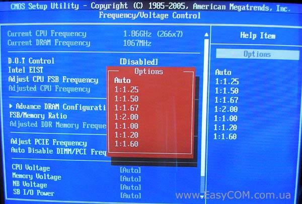
Для установки частоты памяти есть семь делителей, которыми наиболее оптимально можно задать частоту при разгоне.
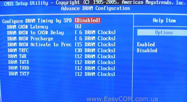
Как обычно, есть возможность настройки таймингов и подтаймингов оперативной памяти, но можно заметить отсутствие настройки 1T/2T Memory Timing, которая изменяет время декодирования команд.

Широкие диапазоны изменения настроек напряжений вполне позволят повысить стабильность системы во время разгона. Кроме того, очень удобно показаны уровни критических величин, что поможет сориентироваться менее опытным пользователям.
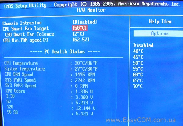
В окне Hardware Monitor можно следить за:
- температурой процессора и материнской платы;
- скоростью вращения процессорного кулера и двух корпусных вентиляторов;
- напряжением на линиях питания 3.3В, 5В, 12В, 5В SB и ядре процессора.
В пункте «CPU Smart FAN Target» можно включить функцию автоматического управления скоростью вращения процессорного кулера.
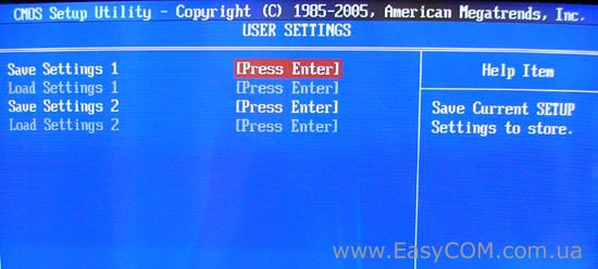
Сохранить удачные пользовательские настройки разгона можно в разделе «User Settings».
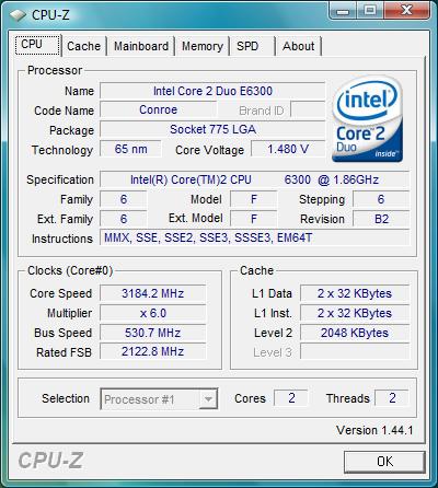
Материнскую плату MSI P35 NEO удалось запустить при частоте системной шины равной 530 МГц. Учитывая большой набор настроек в BIOS, можно предположить очень хорошие возможности разгона процессоров с ее помощью.
Тестирование звукового тракта на основе кодека Realtek ALC888
Общие результаты (RightMark Audio Analyzer)
|
Неравномерность АЧХ (в диапазоне 40 Гц — 15 кГц), дБ |
+0.12, -0.22 |
Очень хорошо |
|
Уровень шума, дБ (А) |
-90.0 |
Хорошо |
|
Динамический диапазон, дБ (А) |
88.5 |
Хорошо |
|
Гармонические искажения, % |
0.0049 |
Очень хорошо |
|
Гармонические искажения + шум, дБ(A) |
-79.0 |
Средне |
|
Интермодуляционные искажения + шум, % |
0.012 |
Очень хорошо |
|
Взаимопроникновение каналов, дБ |
-84.6 |
Очень хорошо |
|
Интермодуляции на 10 кГц, % |
0.014 |
Очень хорошо |
|
Общая оценка |
Очень хорошо |
Тестирование производительности
Для проверки возможностей материнских плат использовалось следующее оборудование.
|
Процессор |
Intel Core 2 Duo E6300 (LGA775, 1,86 ГГц, L2 2 Мб) |
|
Кулер |
Thermaltake Sonic Tower (CL-P0071) + Akasa AK-183-L2B 120 мм |
|
Оперативная пам’ять |
2x DDR2-800 1024 Mб PQI PC6400 |
|
Видеокарта |
EVGA GeForce 8600GTS 256 Mб DDR3 PCI-E |
|
Жесткий диск |
Samsung HD080HJ, 80 Гб, SATA-300 |
|
Оптический привод |
ASUS DRW-1814BLT SATA |
|
Блок питания |
Chieftec CFT-500-A12S 500W, 120 мм вентилятор |
|
Корпус |
CODEGEN M603 MidiTower, 2х 120 мм вентилятора на вдув/выдув |
MSI P35 NEO показывает отличный уровень производительности, как для платы своего класса.
Выводы
Материнская плата MSI P35 NEO является относительно недорогим решением, обладающим неплохими функциональными возможностями и хорошим разгонным потенциалом, который, в каком-то смысле, сумел превзойти наши ожидания. Хотя любителям разгона следует принять во внимание далеко не самый мощный стабилизатор питания процессора. Стоимость MSI P35 NEO является одной из самых низких среди предложений на чипсете Intel P35, при этом явных недостатков у нее почти нет. Разве что, возможно, некоторым будущим владельцам хотелось бы увидеть большее количество слотов PCI, вместо тех же PCI-E x1.
Достоинства:
- поддержка процессоров Intel Penryn, выполненных по 45 нм технологии;
- большое количество настроек BIOS, необходимых для разгона;
- протестированная способность работы шины на частоте 530 МГц;
- 8-канальный звук High Difinition Audio;
- низкая для своего класса стоимость.
Недостатки:
- отсутствие официальной поддержки DDR2-1066;
- очень скромная комплектация;
- только два слота PCI;
- отсутствует внешний S/PDIF;
- отсутствует FireWire контроллер.
Автор: Дмитрий Масюк
Выражаем благодарность фирме ООО ПФ Сервис (г. Днепропетровск) за предоставленные для тестирования материнские платы.

En-1
English
P45 Neo/ G45 Neo
/ P43 Neo
User’s Guide
English
PDF created with pdfFactory Pro trial version www.pdffactory.com

En-4
MS—7519 Mainboard
Quick Components Guide of P45 Neo/ G45 Neo/ P43 Neo
Series (MS-7519 v1.X) Mainboard
Mouse/
Keyboard,
p.En—15
VGA Port,
p.En—15
1394
Port,
p.En—16
USB Port,
p.En—16
LAN,
p.En—16
Audio
Port,
p.En—16
L—In
RS—Out
Serial Port,
p.En—15
Parallel Port,
p.En—15
L—Out
Mic
CS—Out
SS—Out
JPWR2,
p.En—13
CPU,
p.En-5
DIMM1~4,
p.En-7
CPUFAN1, p.En-9
SYSFAN1, p.En-9
JPWR1, p.En—12
IDE1, p.En-9
SYSFAN2, p.En-9
JCI1, p.En—12
SATA1~6, p.En—10
JBAT1, p.En—14
JUSB1~4, p.En—11
JFP1, p.En—10
JFP2, p.En—10
JTPM1,
p.En—13
J1394_1,
p.En—10
FDD1,
p.En-9
JSP1,
p.En—11
JAUD1,
p.En—11
JCD1,
p.En—12
PCI Slot, p.En—14
PCI Express Slot,
p.En—14
JB2/
JB1,
p.En—13
PDF created with pdfFactory Pro trial version www.pdffactory.com

De-4
MS—7519 Mainboard
Übersicht der Eingenschaften der P45 Neo/ G45 Neo/ P43 Neo
Mainboard Series (MS—7519 v1.X)
Maus/
Tastatur,
S.De—15
VGA Port,
S.De—15
1394
Port,
S.De—16
USB Port,
S.De—16
LAN,
S.De—16
Audio
Port,
S.De—16
L—In
RS—Out
Serial Port,
S.De—15
Parallel Port,
S.De—15
L—Out
Mic
CS—Out
SS—Out
JPWR2,
S.De—13
CPU,
S.De-5
DIMM1~4,
S.De-7
CPUFAN1, S.De-9
SYSFAN1, S.De-9
JPWR1, S.De—12
IDE1, S.De-9
SYSFAN2, S.De-9
JCI1, S.De—12
SATA1~6, S.De—10
JBAT1, S.De—14
JUSB1~4, S.De—11
JFP1, S.De—10
JFP2, S.De—10
JTPM1,
S.De—13
J1394_1,
S.De—10
FDD1,
S.De-9
JSP1,
S.De—11
JAUD1,
S.De—11
JCD1,
S.De—12
PCI Slot, S.De—14
PCI Express Slot,
S.De—14
JB2/
JB1,
S.De—13
PDF created with pdfFactory Pro trial version www.pdffactory.com

Fr-4
Carte mère MS-7519
Guide des composants des séries P45 Neo/ G45 Neo/ P43 Neo
Carte mère(MS-7519 v1.X)
Souris/
Clavier,
p.Fr—15
Port VGA,
p.Fr—15
Port
1394,
p.Fr—16
Port USB,
p.Fr—16
LAN,
p.Fr—16
Port
Audio,
p.Fr—16
L—In
RS—Out
Port série,
p.Fr—15
Port
Parallèle,
p.Fr—15
L—Out
Mic
CS—Out
SS—Out
JPWR2,
p.Fr—13
CPU,
p.Fr-5
DIMM1~4,
p.Fr-7
CPUFAN1, p.Fr-9
SYSFAN1, p.Fr-9
JPWR1, p.Fr—12
IDE1, p.Fr-9
SYSFAN2, p.Fr-9
JCI1, p.Fr-12
SATA1~6, p.Fr—10
JBAT1, p.Fr—14
JUSB1~4, p.Fr—11
JFP1, p.Fr-10
JFP2, p.Fr-10
JTPM1,
p.Fr—13
J1394_1,
p.Fr—10
FDD1,
p.Fr-9
JSP1,
p.Fr—11
JAUD1,
p.Fr—11
JCD1,
p.Fr—12
Slot PCI, p.Fr—14
Slot PCI Express,
p.Fr—14
JB2/
JB1,
p.Fr—13
PDF created with pdfFactory Pro trial version www.pdffactory.com

Ru-1
Русский
P45 Neo/ G45 Neo
/ P43 Neo
Руководство
пользователя
Русский
PDF created with pdfFactory Pro trial version www.pdffactory.com
Ru-2
MS—7519 Системная плата
Характеристики
Процессор
— Процессоры Intel
®
Core 2 Extreme, Core 2 Quad, Core 2 Duo,
Pentium Dual—Core и Celeron Dual—Core в конструктиве LGA775
— Многоядерные процессоры Intel
®
45 nm последнего
поколения
*(Для самой новой информации о CPU, посетите сайт
http://global.msi.com.tw/index.php?func=cpuform)
FSB
— 1600* (OC)/ 1333/ 1066/ 800 МГц
Чипсет
— Северный мост: Intel
®
P45/ G45/ P43
— Южный мост: Intel
®
ICH10
Память
— 4 слота DDR2 DIMM поддерживают DDR2 1066**/ 800/ 667
SDRAM (240конт / 1.8V / 16ГБ Max)
(**За дополнительной информацией о совместимых
компонентах посетите сайт http://global.msi.com.tw/index.
php?func=testreport)
LAN
— Поддержка PCIE LAN 10/100/1000 Fast Ethernet на микросхеме
8111C
Аудио
— Интегрированный чипсет Realtek
®
ALC888
— 8-каннальное аудио с гибким переназначением разъема
— Совместимость со спецификацией Azalia 1.0
— Совместимо со спецификацией Microsoft Vista Premium
IDE
— 1 порт IDE на чипсете JMicron JMB 368
— Поддержка режимов Ultra DMA 66/100
— Поддержка режимов работы PIO, Bus Master
SATA
— 6 портов SATAII на чипсете ICH10 (SATA1~6)
— Поддержка скорости передачи данных до 3 Гб/с
PDF created with pdfFactory Pro trial version www.pdffactory.com
Ru-3
Русский
1394 (опционально)
— Поддержка 1394 на чипсете JMicron JMB381
FDD
— 1 флоппи порт
— Поддержка 1 FDD с 360КБ, 720КБ, 1.2МБ, 1.44МБ и 2.88МБ
Коннекторы
Задней панели
— 1 PS/2 порт мыши
— 1 PS/2 порт клавиатуры
— 1 Параллельный порт
— 1 последовательный порт
— 1 порт VGA (для G45 только)
— 4 порта USB 2.0
— 1 разъем LAN
— 6 звуковых разъемов с гибким переназначением
— 1 порт 1394 (опционально)
Разъемы, установленные на плате
— 4 разъема USB 2.0
— 1 разъем 1394 (опционально)
— 1 разъем датчика открывания корпуса
— 1 разъем SPDIF—out
— 1 разъем CD-in
— 1 звуковой разъем для подключения передней панели
— 1 разъем TPM Модуля (опционально)
— 2 перемычки аппаратного разгона FSB (JB1 & JB2)
TPM (опционально)
— Поддержка TPM
Слоты
— 1 слот PCI Express x16, поддержка скорости до PCI Express 2.0
x16
— 2 слота PCI Express x1
— 3 слота PCI, поддержка интерфейса PCI шины с питанием 3.
3В/ 5В
Форм Фактор
— ATX (30.5см X 22.0см)
Крепление
— 6 отверстий для крепления
PDF created with pdfFactory Pro trial version www.pdffactory.com
Ru-4
MS—7519 Системная плата
Руководство по размещению компонентов на системных
компонентах Серий P45 Neo/ G45 Neo/ P43 Neo
(MS—7519 v1.X)
Mouse/
Keyboard,
p.Ru—15
VGA Port,
p.Ru—15
1394
Port,
p.Ru—16
USB Port,
p.Ru—16
LAN,
p.Ru—16
Audio
Port,
p.Ru—16
L—In
RS—Out
Serial Port,
p.Ru—15
Parallel Port,
p.Ru—15
L—Out
Mic
CS—Out
SS—Out
JPWR2,
p.Ru—13
CPU,
p.Ru-5
DIMM1~4,
p.Ru-7
CPUFAN1, p.Ru-9
SYSFAN1, p.Ru-9
JPWR1, p.Ru—12
IDE1, p.Ru-9
SYSFAN2, p.Ru-9
JCI1, p.Ru—12
SATA1~6, p.Ru—10
JBAT1, p.Ru—14
JUSB1~4, p.Ru—11
JFP1, p.Ru—10
JFP2, p.Ru—10
JTPM1,
p.Ru—13
J1394_1,
p.Ru—10
FDD1,
p.Ru-9
JSP1,
p.Ru—11
JAUD1,
p.Ru—11
JCD1,
p.Ru—12
PCI Slot, p.Ru—14
PCI Express Slot,
p.Ru—14
JB2/
JB1,
p.Ru—13
PDF created with pdfFactory Pro trial version www.pdffactory.com

Ru-5
Русский
Эта системная плата поддерживает процессоры от Intel
®
. Для облегчения
установки процессора на ней установлен разъем под названием Socket 775. Если
у вас нет процессорного кулера, пожалуйста, свяжитесь с дилером с целью
приобретения и его установки до того, как включите компьютер.
Самую последнюю информацию о CPU можно получить на сайте http://global.msi.
com.tw/index.php?func=cpuform
Центральный процессор: CPU
Внимание
Перегрев
Перегрев может серьезно повредить CPU и систему. Чтобы уберечь
процессор от перегрева, убедитесь в том, что процессорный кулер
работает нормально. Чтобы увеличить теплорассеивание, убедитесь в
том, что нанесен слой теплопроводящей пасты (или теплопроводящей
ленты) между CPU и радиатором.
Замена CPU
При замене CPU, во избежание его повреждения, обязательно отключите
источник питания или выньте вилку блока питания из розетки.
Разгон
Эта системная плата поддерживает “разгон”. Однако, убедитесь, что
компоненты системы способны работать в таких нестандартных режимах
при разгоне. Не рекомендуется использовать продукт в режимах, не
соответствующих указанным в спецификациях. Мы не гарантируем
защиту от повреждений и рисков, вызванных неправильной
эксплуатацией и установкой параметров с превышением
характеристик.
PDF created with pdfFactory Pro trial version www.pdffactory.com
Ru-6
MS—7519 Системная плата
Установка процессора и вентилятора для Socket 775
1. Разъем процессора закрыт пластиковой крышкой, которая
защищает контакты разъема от повреждений и загрязнений. Если
процессор не установлен в разъем, необходимо всегда закрывать
его пластиковой крышкой для защиты от пыли и повреждений.
2. Снимите крышку, подняв её с одной стороны.
3. Откроются контакты разъема.
4. Откройте рычажку.
5. Поднимите рычаг и откройте разъем для установки процессора.
6. Убедившись в правильной ориентации процессора, положите
процессор в разъем. Обратите внимание, что выемки на процессоре
должны соответствовать выступам на процессорном разъеме.
7. Проверьте правильность установки процессора в разъем
визуально. Если процессор установлен неправильно, то выньте
процессор и переустановите.
8. Опустите мателлическую крышку механизма крепления.
9. Аккуратно опустите рычаг на крышку механизма крепления и
зафиксируйте его. Для фиксации рычага в механизме крепления
предусмотрен маленький крючок.
10.Совместите отверстия системной платы с защелками крепления
вентилятора. Прижмите радиатор с вентилятором к процессору
и проследите, чтобы четыре защелки вошли в отверстия
системной платы.
11.Нажмите на четыре защелки и закрепите вентилятор. Затем поверните
фиксаторы защелок (направление поворота указано на вентиляторе)
и закрепите их.
12.Переверните системную плату и убедитесь, что защелки надежно удерживают
вентилятор.
alignment key
Внимание
1. Смотрите состояние процессора в разделе BIOS.
2. Если процессор не установлен, всегда закрывайте разъем пластиковой
крышкой для предотвращения поломок и попадания в него грязи и пыли.
3. Фото системной платы, размещенные в этой части, приведены только
для демонстрации установки вентилятора. Внешний вид системной
платы зависит от модели, купленной вами.
PDF created with pdfFactory Pro trial version www.pdffactory.com
Ru-7
Русский
Память
Внимание
— Модули DDR2 не взаимозаменяемы с модулями DDR, и стандарт DDR2 не
имеет обратной совместимости. Следует установить модули памяти DDR2
в разъемы DDR2.
— Для работы в двухканальном режиме убедитесь, что в разъемах разных
каналов у вас установлены модули одного типа и одинаковой ёмкости.
— Чтобы система загрузилась, в начале установите модули в разъемы DIMM1.
DDR2: DIMM1~4
Эти слоты DIMM используются для установки модулей памяти.
За дополнительной информацией о совместимых компонентах посетите сайт
http://global.msi.com.tw/index.php?func=testreport
64x2=128 pin 56x2=112 pin
Общая правила двухканального режима
В двухканальном режимемодули памяти могут передавать и принимать
данные по 2 шинам одновременно. При использовании двухканального
режима производительность системы повышается. Ниже приведены
правила заполнения слотов памяти для работы в двухканальном режиме.
DIMM1
DIMM2
DIMM3
DIMM4
DIMM1
DIMM2
DIMM3
DIMM4
Empty
PDF created with pdfFactory Pro trial version www.pdffactory.com
Ru-8
MS—7519 Системная плата
Установка модулей памяти
Сориентируйте относительно друг друга прорезь на модуле памяти и ключ в
слоте DIMM. Следуйте нижеследующим указаниям для правильной установки.
1. Модули памяти имеют только одну прорезь в середине. Модуль войдет в разъем
только при правильной ориентации.
2. Вставьте модуль в DIMM слот в вертикальном направлении. Затем нажмите на
него, чтобы золоченые контакты глубоко погрузились в DIMM слот. Если модуль
памяти вставлен правильно, то пластиковые защелки на обоих концах
закроются автоматически.
3. Вручную убедитесь, что модуль закреплен в слоте DIMM защелками с обеих
сторон.
Внимание
Золотые контакты едва видны, если модули памяти правильно размещены
в DIMM слоте.
Volt
Notch
PDF created with pdfFactory Pro trial version www.pdffactory.com
Ru-9
Русский
Коннекторы, перемычки, разъемы
Разъем FDD: FDD1
Разъем поддерживает FDD емкостью 360КБ, 720КБ, 1.2МБ, 1.44МБ или 2.88МБ.
Разъемы питания вентиляторов: CPUFAN1/ SYSFAN1/ SYSFAN2
Разъемы питания вентиляторов поддерживают вентиляторы с питанием +12V.
Вентилятор процессора поддерживает функцию Smart FAN. При подключении
необходимо помнить, что красный провод подключается к шине +12V, черный — к
земле GND. Если на системной плате установлена микросхема аппаратного
мониторинга, необходимо использовать специальные вентиляторы с датчиками
скорости для реализации функции управления вентиляторами.
Разъем IDE: IDE1
Разъем поддерживает жёсткий диск IDE, дополнительное дисковое устройство и
другие устройства IDE.
Внимание
1. Чтобы узнать о моделях подходящих вентиляторов обратитесь,
пожалуйста, к информации о рекомендуемых вентиляторах для процессора
на официальном веб сайте или проконсультируйтесь с продавцом.
2.CPUFAN поддерживает управление скоростью вращения вентилятора. Для
автоматического контроля скорости вентилятора процессора, зависящей
от температуры процессора, можно установить Dual Core Center.
3. Разъем CPUFAN поддерживает вентиляторы, как с 3, так и с 4 контактами.
Внимание
При подключении двух устройств в одном кабеле, следует установить
устройства в режим Master/ Slave посредством установки перемычки. За
инструкциями обратитесь к документации изготовителя устройства.
CPUFAN1
SENSOR
+12V
GND
Control
SYSFAN1/2
SENSOR or NC
+12V
GND
PDF created with pdfFactory Pro trial version www.pdffactory.com
Ru—10
MS—7519 Системная плата
Коннекторы передней панели: JFP1, JFP2
Эти коннекторы используются для подключения кнопок и индикаторов,
расположенных на передней панели корпуса. Коннектор JFP1 соответствует
руководству Intel
®
Front Panel I/O Connectivity Design Guide.
IEEE1394 Connector (Зеленый): J1394_1 (опционально)
Этот коннектор позволяет подключить порты IEEE1394 на выносной планке
IEEE1394.
Разъем Serial ATA: SATA1~6
Данный разъем является высокоскоростным портом интерфейса Serial ATA. Любой
разъем Serial ATA может соединяться с одним устройством Serial ATA.
Внимание
Избегайте, пожалуйста, резких изгибов кабеля Serial ATA. В противном
случае могут возникнуть потери данных при передаче.
IEEE1394 Bracket
(опционально)
JFP2JFP1
7
8
Power LED
Speaker
1
2
1
2
9
10
HDD
LED
Reset
Switch
Power
LED
Power
Switch
1
2
9
10
TPA-
Ground
TPB-
Cable power
Ground
TPA+
Ground
TPB+
Cable power
Key (no pin)
PDF created with pdfFactory Pro trial version www.pdffactory.com
Ru—11
Русский
Выносные порты USB (Желтый коннектор): JUSB1~4
Разъем, соответствует спецификации Intel
®
I/O Connectivity Design, идеально
подходит для подключения таких высокоскоростных периферийных устройств,
как USB HDD, цифровые камеры, MP3 плееры, принтеры и им подобные.
Внимание
Помните, что во избежание повреждений, контакты VCC и GND должны
быть правильно подключены.
Выносной разъем аудио : JAUD1
Этот коннектор позволяет подключить выносной разъем аудио на передней панели
и соответствует руководству I/O Connectivity Design Guide.
USB 2.0 Bracket
(опционально)
Коннектор S/PDIF—Out: JSP1
Этот разъем используется для подключения интерфейса S/PDIF (Sony & Philips
Digital Interconnect Format) для передачи звука в цифровом формате.
SPDIF Bracket
(опционально)
USBOC
10
1 2
VCC
USB0-
USB0+
GND
Key (no pin)
VCC
USB1-
USB1+
GND
9
VCC
SPDIF_out
GND
1
2
9
10
MIC _L
MIC _R
LINE out_R
Front_JD
LINE out_L
Ground
Presence#
MIC_JD
NC(No pin)
LINE out_JD
PDF created with pdfFactory Pro trial version www.pdffactory.com
Ru—12
MS—7519 Системная плата
Дополнение источника питания
Перед подключением разъема питания, во избежание повреждений обязательно
убедитесь, что все компоненты установлены правильно. Все разъемы питания
должны быть подключены к блоку питания ATX для облегчения стабильной работы
системной платы.
24-контактный разъем питания ATX: JPWR1
Этот разъем позволяет подключить 24-контактный питания ATX. Для подключения
источника убедитесь, что его разъем и контакты правильно сориентированы.
Затем плотно вставьте его в разъем на системной плате.
Вы также можете использовать 20-контактный ATX блок питания. При
использовании 20-контактного разъема, подключайте его вдоль контактов 1 и 13.
1
1224
13
+3.3V
+3.3V
GND
+5V
GND
+5V
GND
PWR OK
5VSB
+12V
+12V
+3.3V
GND
+5V
+5V
+5V
NC
GND
GND
GND
PS—ON#
GND
—12V
+3.3V
Коннектор CD—In: JCD1
Этот коннектор предназначен для подключения внешного входа аудио.
Разъем датчика открывания корпуса: JCI1
К этому коннектору подключается кабель датчика, установленного в корпусе.
При открывании корпуса его механизм активизируеся. Система запоминает это
событие и выдает предупреждение на экран. Предупреждение можно отключить в
настройках BIOS.
1
2
CINTRU
GND
GND
R L
PDF created with pdfFactory Pro trial version www.pdffactory.com
Ru—13
Русский
Разъем питания ATX 12V (2x2—Pin): JPWR2
Этот разъем питания 12В используется для обеспечения питания процессора.
1
34
2
GND
12V
GND
12V
РазъемTPM Модуля: JTPM1 (опционально)
Данный разъем подключается к модулю TPM (Trusted Platform Module)
(опционально). За более подробной информацией и возможностями применения
обращайтесь к Описанию модуля TPM.
2
1
14
13
3Vdual / 3V_STB LCLK
LRST#
LAD0
LAD1
LAD2
LAD3
LFRAME#
VCC3
SIRQ
VCC5
Key(no pin)
GND
GND
Перемычки аппаратного разгона FSB: JB1, JB2 (опционально)
Перестановка перемычек JB1 и JB2 позволяет разогнать FSB для увеличения
частоты процессора. Следуйте нижеследующим указанием для установки FSB.
200—>266 МГц 200—>333 МГц 200—>400 МГц
266—>400 МГц
333—>400 МГц
(по умолчанию)
1
JB1
JB2
1 3 1
3
1 3
1 3
1
3
JB1
JB2
266—>333 МГц
Внимание
1. Перед перестановкой перемычек убедитесь в том, что источник питания
отключен.
2. Если разгон вызывает нестабильность системы или проблемы при
загрузке, то восстановите перемычки в положение по умолчанию.
PDF created with pdfFactory Pro trial version www.pdffactory.com
Ru—14
MS—7519 Системная плата
Слот PCI Express (x16/ x1)
Слот PCI Express поддерживает карт расширения интерфейса PCI Express.
Слот PCI Express x16
Слот PCI Express x1
Слот PCI (Peripheral Component Interconnect)
Слот PCI позволяет установить карту LAN, SCSI, USB и другие дополнительные
карты расширения, которые соответствуют характеристикам PCI.
Перемычка очистки CMOS: JBAT1
На плате установлена CMOS память с питанием от батарейки, хранящая данные
о конфигурации системы. Данные, хранящиеся в CMOS памяти, требуются
компьютеру для загрузки операционной системы при включении. Если у вас
возникает необходимость сбросить конфигурацию системы (очистить CMOS),
воспользуйтесь этой перемычкой.
1
Очистка
1
Хранение ( обычно)
1
Внимание
Очистка CMOS производится соединением контактов 2—3 при отключенной
системе. Затем следует вернуться к соединению контактов 1—2. Избегайте
очистки CMOS при работающей системе: это повредит системную плату.
Внимание
Перед установкой или извлечением карт расширения убедитесь, что кабель
питания отключен от электрической сети. Прочтите документацию на
карту расширения и выполните необходимые аппаратные или програмные
установки для данной платы, такие как перемычки, переключатели или
конфигурацию BIOS.
PDF created with pdfFactory Pro trial version www.pdffactory.com
Ru—15
Русский
Задняя панель
Разъемы мыши/клавиатуры
Стандартные разъемы DIN PS/2
®
для подключения мыши/клавиатуры с
интерфейсом PS/2
®
.
Разъем параллельного порта
Параллельный порт — это стандартный порт для принтера. Он поддерживает режимы
EPP (усовершенствованный параллельный порт) и ECP (параллельный порт с
дополнительными возможностями).
Разъем последовательного порта
Это высокоскоростной последовательный порт связи 16550A с 16-битной
передачей FIFO. К этому разъему можно непосредственно подключить мышь для
последовательного порта или другое устройство.
Разъем VGA
15-контактная розетка DB для подключения монитора.
(9-контактная вилка)
1 5
6 9
Разъем PS/2 для мыши (6-контактная зеленая
розетка)
Разъем PS/2 для клавиатуры (6-контактная
фиолетовая розетка)
13 1
1425
(25-контактная розетка)
(15-контактная розетка DIN)
15
1115
PDF created with pdfFactory Pro trial version www.pdffactory.com
Ru—16
MS—7519 Системная плата
Порт USB
Порт USB (Universal Serial Bus) позволяет подключать такие USB устройства, как
клавиатуру, мышь или т.д.
Аудио разъемы
Эти разъемы используются для подключения звуковых устройств. Разъемы,
выполняющие разные функции, имеют различные цвета.
Выход Line (Голубой) — Линейный вход, используется для подключения внешнего
CD проигрывателя, магнитофона или других звуковых устройств.
Выход Line (Зеленый) — Линейный выход для подключения наушников или колонок.
MIC (Розовый) — Разъем для подключения микрофона.
Выход RS (Черный) — Выход на задние колонки в режиме 4/ 5.1/ 7.1.
Выход CS (Оранжевый)
— Выход на центральную колонку и сабвуфер в режиме 5.1/ 7.1.
Выход SS (Серый) — Выход на боковые колонки в режиме 7.1.
Порт 1394
Порт 1394 на задней панели позволяет подключать устройства с интерфейсом
IEEE1394.
Разъем LAN
Стандартный разъем RJ—45 для подключения к локальной вычислительной сети
(LAN). К нему подключается кабель локальной сети.
LED Цвет Состояние LED Описание
Нет LAN соединение не установлено.
Лев. Оранж. Есть (постоянно) LAN соединение установлено.
Есть (пульсирует) Связъ с другим компьютером по LAN.
Зелен. Нет Скорость передачи 10 Мб/с.
Прав. Есть Скорость передачи 100 Мб/с.
Оранж. Есть Скорость передачи 1000 Мб/с.
PDF created with pdfFactory Pro trial version www.pdffactory.com