-
Contents
-
Table of Contents
-
Bookmarks
Quick Links
P35 Neo/ G33 Neo series
MS-7360 (V1.X) Mainboard
G52-73601X1
i
Related Manuals for MSI P35 Neo series
Summary of Contents for MSI P35 Neo series
-
Page 1
P35 Neo/ G33 Neo series MS-7360 (V1.X) Mainboard G52-73601X1… -
Page 2: Copyright Notice
If a problem arises with your system and no solution can be obtained from the user’s manual, please contact your place of purchase or local distributor. Alternatively, please try the following help resources for further guidance. Visit the MSI website for FAQ, technical guide, BIOS updates, driver updates, and other information: http://www.msi.com.tw/program/service/faq/ faq/esc_faq_list.php…
-
Page 3: Safety Instructions
Safety Instructions Always read the safety instructions carefully. Keep this User’s Manual for future reference. Keep this equipment away from humidity. Lay this equipment on a reliable flat surface before setting it up. The openings on the enclosure are for air convection hence protects the equip- ment from overheating.
-
Page 4: Fcc-B Radio Frequency Interference Statement
FCC-B Radio Frequency Interference Statement T h is eq uip men t h as been tested and found to c omply with the limits for a Class B digital device, pursuant to Part 15 of the FCC Rules. These limits are designed to provide reasonable protection against harmful interference in a residential installation.
-
Page 5: Weee (Waste Electrical And Electronic Equipment) Statement
WEEE (Waste Electrical and Electronic Equipment) Statement…
-
Page 8: Table Of Contents
CONTENTS Copyright Notice ………………….ii Trademarks ……………………ii Revision History ………………….ii Technical Support ………………….ii Safety Instructions ………………….iii FCC-B Radio Frequency Interference Statement …………iv W EEE (Waste Electrical and Electronic Equipment) Statement ……..v Chapter 1 Getting Started ………………1-1 Mainboard Specifications ……………….
-
Page 9
Clock ……………………A-6 Voltage ……………………. A-7 FAN Speed ………………….A-8 Temperature ………………….A-9 User Profile ………………….A-10 Appendix B Realtek ALC888 Audio …………..B-1 Installing the Realtek Audio Driver …………..B-2 Software Configuration ………………B-4 Hardware Setup ………………..B-19… -
Page 10: Chapter 1 Getting Started
Getting Started Chapter 1 Getting Started Thank you for choosing the P35 Neo/ G33 Neo Series (MS-7360 v1.X) ATX mainboard. The P35 Neo/ G33 Neo ® Series mainboards are based on Intel P35/G33 & ICH9/ ICH9R chipsets for optimal system efficiency. Designed ®…
-
Page 11: Mainboard Specifications
Processor Support ® — Intel Core 2 Extreme, Core 2 Quad, Core 2 Duo, Pentium and Celeron in the LGA775 package (For the latest information about CPU, please visit http://www.msi. com.tw/cpusupport.htm) Supported FSB — 1333/ 1066/ 800 MHz Chipset ®…
-
Page 12
Getting Started Floppy — 1 floppy port — Supports 1 FDD with 360KB, 720KB, 1.2MB, 1.44MB and 2.88MB Connectors Back panel — 1 PS/2 mouse port — 1 PS/2 keyboard port — 1 Parallel port supporting SPP/EPP/ECP mode — 1 serial port (COM1) — 1 VGA port (for G33 Neo series only) — 1 IEEE1394 port (optional) — 4 USB 2.0 Ports… -
Page 13: Mainboard Layout
M S-7360 M ainboard Mainboard Layout CPUFAN1 Top : mouse Bottom: keyboard JPW1 Top : Parallel Port Bottom: COM portA VGA port (optional) Top:1394 (optional ) Bottom: USB ports Int el P35/ G33 Top: LAN Jack Bottom: USB ports Line-In Line-Out T:RS-Out M:CS- Ou t…
-
Page 14: Packing Checklist
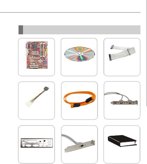
Getting Started Packing Checklist Standard Cable for MSI Driver/Utility CD IDE Devices (Optional) MSI motherboard USB Bracket (Optional) SATA Cable Power Cable Back IO Shield 1394 Bracket (Optional) User’s Guide * The pictures are for reference only and may vary from the packing contents of the…
-
Page 15: Chapter 2 Hardware Setup
Hardware Setup Chapter 2 Hardware Setup This chapter provides you with the information about hardware setup procedures. While doing the installation, be careful in holding the components and follow the installation procedures. For some components, if you install in the wrong orientation, the components will not work properly.
-
Page 16: Quick Components Guide
M S-7360 M ainboard Quick Components Guide SYSFAN2, CPU, p.2-3 DDRII DIMMs, p.2-7 p.2-14 JPW1, p.2-9 CPUFAN1, p.2-14 Back Panel I/O, p.2-10 IDE1, p.2-12 JPWR3, p.2-9 PCI Express slots, p.2-20 SYSFAN1, p.2-14 JBAT1, SATA1~7, p.2-19 p.2-13 CD_IN1, JUSB1~4, p.2-14 p.2-16 PCI Slots, p.2-20 JFP1, p.2-18…
-
Page 17: Cpu (Central Processing Unit)
Celeron processor in LGA 775 package. When you are installing the CPU, make sure to install the cooler to prevent overheating. If you do not have the CPU cooler, consult your dealer before turning on the computer. For the latest information about CPU, please visit http://www.msi.com.tw/testreport.htm Important Overheating Overheating will seriously damage the CPU and system.
-
Page 18: Cpu & Cooler Installation
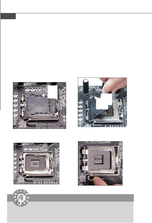
M S-7360 M ainboard CPU & Cooler Installation W hen you are installing the CPU, make sure the CPU has a cooler attached on the top to prevent overheating. Meanwhile, do not forget to apply some thermal paste on CPU before installing the heat sink/cooler fan for better heat dispersion. Follow the steps below to install the CPU &…
-
Page 19
Hardware Setup 5. Lift the load lever up and open the 6. After confirming the CPU direction load plate. for correct mating, put down the CPU in the socket housing frame. Be sure to grasp on the edge of the CPU base. Note that the align- ment keys are matched. -
Page 20
M S-7360 M ainboard 9. Press down the load lever lightly 10. Align the holes on the mainboard onto the load plate, and then se- with the heatsink. Push down the cure the lever with the hook under c ooler u nti l i ts f ou r c lip s g et retention tab. -
Page 21: Memory
Hardware Setup Memory These DIMM slots are used for installing memory modules. For more information on compatible components, please visit http://www.msi.com. tw/testreport.htm DDR2 240-pin, 1.8V 56×2=112 pin 64×2=128 pin Dual-Channel mode Population Rule In Dual-Channel mode, the memory modules can transmit and receive data with two data bus lines simultaneously.
-
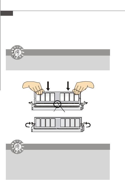
Page 22: Installing Memory Modules
M S-7360 M ainboard Installing Memory Modules 1. The memory module has only one notch on the center and will only fit in the right orientation. 2. Insert the memory module vertically into the DIMM slot. Then push it in until the golden finger on the memory module is deeply inserted in the DIMM slot.
-
Page 23: Power Supply
Hardware Setup Power Supply ATX 24-Pin Power Connector: JPWR3 This connector allows you to connect an ATX 24-pin power supply. pin 13 To connect the ATX 24-pin power supply, make sure the plug of the power supply is inserted in the proper orientation and the pins are aligned.
-
Page 24: Back Panel
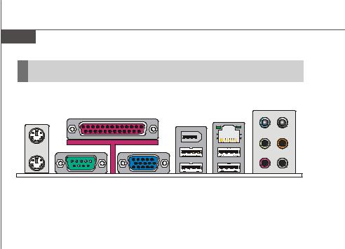
M S-7360 M ainboard Back Panel Parallel Port (optional) Mouse 1394 Port Line-In RS-Out Line-Out CS-Out SS-Out USB Ports Keyboard VGA Port Serial Port (optional) M ouse/Keyboard Connector ® ® The standard PS/2 mouse/keyboard DIN connector is for a PS/2 mouse/keyboard.
-
Page 25
Hardware Setup LAN (RJ-45) Jack The standard RJ-45 jack is for connection Activity Indicator Link Indicator to single Local Area Network (LAN). You can connect a network cable to it. Color LED State condition LAN link is not established. Left Orange On (steady state) LAN link is established. -
Page 26: Connectors
M S-7360 M ainboard Connectors Floppy Disk Drive Connector: FDD1 This connector supports 360KB, 720KB, 1.2MB, 1.44MB or 2.88MB floppy disk drive. FDD1 IDE Connector: IDE1 This connector supports IDE hard disk drives, optical disk drives and other IDE devices. IDE1 Important If you install two IDE devices on the same cable, you must configure the…
-
Page 27
Hardware Setup Serial ATA Connector: SATA1/ SATA2/ SATA3/ SATA4/ SATA5/ SATA6/ SATA7 (SATA5 & SATA6 are for ICH9R only, SATA7 is con- trolled by Marvell 88SE6111) This connector is a high-speed Serial ATA interface port. Each connector can con- nect to one Serial ATA device. SATA7 (optional) SATA6… -
Page 28
M S-7360 M ainboard Fan Power Connectors: CPUFAN1, SYSFAN1, SYSFAN2 The fan power connectors support system cooling fan with +12V. W hen connecting the wire to the connectors, always note that the red wire is the positive and should be connected to the +12V; the black wire is Ground and should be connected to GND. If the mainboard has a System Hardware Monitor chipset on-board, you must use a specially designed fan with speed sensor to take advantage of the CPU fan control. -
Page 29
Hardware Setup Front Panel Audio Connector: JAUD1 This connector allows you to connect the front panel audio and is compliant with ® Intel Front Panel I/O Connectivity Design Guide. JAUD1 HD Audio Pin Definition SIGNAL DESCRIPTION MIC_L Microphone — Left channel Ground MIC_R Microphone — Right channel… -
Page 30
M S-7360 M ainboard Front USB Connector: JUSB1 / JUSB2 / JUSB3 / JUSB4 ® This connector, compliant with Intel I/O Connectivity Design Guide, is ideal for con- necting high-speed USB interface peripherals such as USB HDD, digital cameras, M P3 players, printers, modems and the like. Pin Definition SIGNAL SIGNAL… -
Page 31
Hardware Setup S/PDIF-Out Connector: JSPD1 (Optional) This connector is used to connect S/PDIF (Sony & Philips Digital Interconnect Format) interface for digital audio transmission. SPDIF-out JSPD1 S/PDIF Bracket (Optional) IEEE1394 Connector: J1394_1 (Optional) This connector allows you to connect the IEEE1394 device via an optional IEEE1394 bracket. -
Page 32: Front Panel Connectors: Jfp1, Jfp2
M S-7360 M ainboard Front Panel Connectors: JFP1, JFP2 These connectors are for electrical connection to the front panel switches and LEDs. ® The JFP1 is compliant with Intel Front Panel I/O Connectivity Design Guide. Power Power Switch JFP1 Reset Switch JFP1 Pin Definition SIGNAL…
-
Page 33: Jumper
Hardware Setup Jumpers Clear CMOS Jumper: JBAT1 There is a CMOS RAM onboard that has a power supply from an external battery to keep the data of system configuration. W ith the CMOS RAM, the system can auto- matically boot OS every time it is turned on. If you want to clear the system configuration, set the jumper to clear data.
-
Page 34: Slots
M S-7360 M ainboard Slots PCI (Peripheral Component Interconnect) Express Slot The PCI Express slot supports the PCI Express interface expansion card. The PCI Express x 16 supports up to 4.0 GB/s transfer rate. The PCI Express x 8 supports up to 2.0 GB/s transfer rate. The PCI Express x 4 supports up to 1.0 GB/s transfer rate.
-
Page 35: Chapter 3 Bios Setup
BIOS Setup Chapter 3 BIOS Setup This chapter provides information on the BIOS Setup program and allows you to configure the system for optimum use. You may need to run the Setup program when: ² An error message appears on the screen during the system booting up, and requests you to run SETUP.
-
Page 36: Entering Setup
M S-7360 M ainboard Entering Setup Power on the computer and the system will start POST (Power On Self Test) process. W hen the message below appears on the screen, press <DEL> key to enter Setup. Press DEL to enter SETUP If the message disappears before you respond and you still wish to enter Setup, restart the system by turning it OFF and On or pressing the RESET button.
-
Page 37: Control Keys
BIOS Setup Control Keys < ↑> Move to the previous item < ↓> Move to the next item < ←> Move to the item in the left hand < →> Move to the item in the right hand <Enter> Select the item <Esc>…
-
Page 38: The Main Menu
M S-7360 M ainboard The Main Menu Standard CM OS Features Use this menu for basic system configurations, such as time, date etc. Advanced BIOS Features ® Use this menu to setup the items of AMI special enhanced features. Integrated Peripherals Use this menu to specify your settings for integrated peripherals.
-
Page 39
BIOS Setup Load Optimized Defaults Use this menu to load the default values set by the mainboard manufacturer specifi- cally for optimal performance of the mainboard. BIOS Setting Password Use this menu to set the password for BIOS. Save & Exit Setup Save changes to CMOS and exit setup. -
Page 40: Standard Cmos Features
M S-7360 M ainboard Standard CMOS Features The items in Standard CMOS Features Menu includes some basic setup items. Use the arrow keys to highlight the item and then use the <PgUp> or <PgDn> keys to select the value you want in each item. Date (MM:DD:YY) This allows you to set the system to the date that you want (usually the current date).
-
Page 41
BIOS Setup LBA/Large M ode This allows you to enable or disable the LBA Mode. Setting to Auto enables LBA mode if the device supports it and the devices is not already formatted with LBA mode disabled. DM A M ode Select DMA Mode. -
Page 42: Advanced Bios Features
M S-7360 M ainboard Advanced BIOS Features Boot Sector Protection This function protects the BIOS from accidental corruption by unauthorized users or computer viruses. W hen enabled, the BIOS’ data cannot be changed when attempt- ing to update the BIOS with a Flash utility. To successfully update the BIOS, you’ll need to disable this Flash BIOS Protection function.
-
Page 43
BIOS Setup IOAPIC Function This field is used to enable or disable the APIC (Advanced Programmable Interrupt Controller). Due to compliance with PC2001 design guide, the system is able to run in APIC mode. Enabling APIC mode will expand available IRQ resources for the system. MPS Table Version This field allows you to select which MPS (Multi-Processor Specification) version to be used for the operating system. -
Page 44
M S-7360 M ainboard Boot Sequence Press <Enter> to enter the sub-menu and the following screen appears: 1st/ 2nd/ 3rd Boot Device The items allow you to set the first/ second/ third boot device where BIOS attempts to load the disk operating system. Boot From Other Device Setting the option to [Yes] allows the system to try to boot from other device. -
Page 45: Integrated Peripherals
BIOS Setup Integrated Peripherals USB Controller This setting allows you to enable/disable the onboard USB controller. USB Device Legacy Support Select [Enabled] if you need to use a USB-interfaced device in the operating system. Onboard LAN Controller This item is used to enable/disable the onboard LAN controller. LAN Option ROM This item is used to decide whether to invoke the Boot ROM of the LAN controller.
-
Page 46
M S-7360 M ainboard On-Chip ATA Devices Press <Enter> to enter the sub-menu and the following screen appears: PCI IDE BusMaster This item allows you to enable/ disable BIOS to used PCI busmastering for reading/ writing to IDE drives. On-Chip SATA Controller This setting is used to specify the operating mode for SATA devices. -
Page 47: Power Management Setup
BIOS Setup Power Management Setup Important S3-related functions described in this section are available only when your BIOS supports S3 sleep mode. ACPI Function This item is to activate the ACPI (Advanced Configuration and Power Management Interface) Function. If your operating system is ACPI-aware, such as W indows 2000/ XP, select [Enabled].
-
Page 48
M S-7360 M ainboard Re-Call VGA BIOS From S3 W hen ACPI Standby State is set to [S3], users can select the options in this field. Selecting [Enabled] allows BIOS to call VGABIOS to initialize the VGA card when system wakes up (resumes) from S3 sleep state. The system resume time is short- ened when you disable the function, but system will need an VGA driver to initialize the VGA card. -
Page 49
BIOS Setup Resume From S3 by PS/2 Mouse This setting determines whether the system will be awakened from what power saving modes when input signal of the PS/2 mouse is detected. Resume by PCI Device (PME#) W hen set to [Enabled], the feature allows your system to be awakened from the power saving modes through any event on PME (Power Management Event). -
Page 50: Pnp/Pci Configurations
M S-7360 M ainboard PNP/PCI Configurations This section describes configuring the PCI bus system and PnP (Plug & Play) feature. PCI, or Peripheral Component Interconnect, is a system which allows I/O devices to operate at speeds nearing the speed the CPU itself uses when communicating with its special components.
-
Page 51
BIOS Setup IRQ Resource Setup Press <Enter> to enter the sub-menu and the following screen appears. IRQ 3/4/5/7/9/10/11/14/15 These items specify the bus where the specified IRQ line is used. The settings determine if AMIBIOS should remove an IRQ from the pool of avail- able IRQs passed to devices that are configurable by the system BIOS. -
Page 52: H/W Monitor
M S-7360 M ainboard H/W Monitor Chassis Intrusion The field enables or disables the feature of recording the chassis intrusion status and issuing a warning message if the chassis is once opened. To clear the warning message, set the field to [Reset]. The setting of the field will automatically return to [Enabled] later.
-
Page 53: Frequency/Voltage Control
D.O.T Control D.O.T. (Dynamic Overclocking Technology) is the automatic overclocking function, ’s newly developed CoreCell included in the MSI Technology. It is designed to detect the load balance of CPU while running programs, and to adjust the best CPU frequency automatically. W hen the motherboard detects CPU is running programs, it will speed up CPU automatically to make the program run smoothly and faster.
-
Page 54
M S-7360 M ainboard [Sergeant] 2nd level of overclocking, increasing the frequency by 3%. [Captain] 3rd level of overclocking, increasing the frequency by 5%. [Colonel] 4th level of overclocking, increasing the frequency by 7%. [General] 5th level of overclocking, increasing the frequency by 10%. [Commander] 6th level of overclocking, increasing the frequency by 15%. -
Page 55
BIOS Setup DRAM RAS# to CAS# Delay This field allows you to set the number of cycles for a timing delay between the CAS and RAS strobe signals, used when DRAM is written to, read from or refreshed. Fast speed offers faster performance while slow speed offers more stable performance. -
Page 56
M S-7360 M ainboard VTT FSB Voltage This item allows you to set the FSB VTT voltage. Spread Spectrum Configuration CPU Spread Spectrum This setting is used to enable or disable the Spread Spectrum feature. W hen overclocking, always set it to [Disabled]. Important 1. -
Page 57: Load Fail-Safe/ Optimized Defaults
BIOS Setup Load Fail-Safe/ Optimized Defaults The two options on the main menu allow users to restore all of the BIOS settings to the default Fail-Safe or Optimized values. The Optimized Defaults are the default values set by the mainboard manufacturer specifically for optimal performance of the mainboard.
-
Page 58: Bios Setting Password
M S-7360 M ainboard BIOS Setting Password W hen you select this function, a message as below will appear on the screen: Type the password, up to six characters in length, and press <Enter>. The password typed now will replace any previously set password from CMOS memory. You will be prompted to confirm the password.
-
Page 59: Appendix A Dual Core Center
Dual Core Center Dual CoreCenter, the most useful and powerful utility that MSI has spent muc h researc h and ef forts to develop, helps users to monitor or configure the hard- ware status of MSI Mainboard & MSI Graphics card in windows, such as CPU/GPU clock, voltage, fan speed and temperature.
-
Page 60: Activating Dual Core Center
Activating Dual Core Center Once you have your Dual Core Center installed (locate the setup source file in the setup CD accompanying with your mainboard, path: Utility —> MSI Utility —> Dual Core Center), it will have an icon in the system tray, a short cut icon on the desktop, and a short cut path in your “Start-up”…
-
Page 61: Main
Dual Core Center Main Before using this utility, we have to remind you: only when installing the MSI V044 (V044 has to install with the version 8.26 or newer driver)/ V046 or V060 graphics card can activate the full function of this utility. If you install a graphics card of other brand, only hardware status of the MSI mainboard would be available.
-
Page 62
M S-7360 M ainboard AV/ Game/ Office/ Silence/ Cool MSI provides five common settings for different environments. The settings had been set to optimal values to reac h better performanc e in eac h environment. Click the button you need. -
Page 63: Dot(Dynamic Over Clocking
Dynamic Overclocking Technology is an automatic overclocking function, included in ’s newly developed Dual CoreCenter Technology. It is designed to detect the the MSI loading of CPU/ GPU while running programs, and to over-clock automatically. When the motherboard detects that the loading of CPU is exceed the default threshold for a time, it will speed up the CPU and fan automatically to make the system run smoother and faster.
-
Page 64: Clock
M S-7360 M ainboard Clock In the Clock sub-menu, you can see clock status (including FSB/ CPU clock of mainboard and GPU/ memory clock of graphics card) of your system. And you can select desired value for overclocking. There will be several items for you to select for overclocking after you click button.
-
Page 65: Voltage
Dual Core Center Voltage In the Voltage sub-menu, you can see voltage status (including Vcore, memory, GPU voltage… etc.) of your system, and you can select desired value for overclocking. It will show several items to select for overclocking after you click the button.
-
Page 66: Fan Speed
M S-7360 M ainboard FAN Speed In the FAN Speed sub-menu, you can read fan status of your system. Select higher speed for better cooling effect. There are several sections for you to change the fan speed to a section after clicking button.
-
Page 67: Temperature
Dual Core Center Temperature In the Temperature sub-menu, you can see temperature status of your system. On the underside, it shows the graphs of the temperatures. Only the curves of the item which the button is lit up with red color will be shown.
-
Page 68: User Profile
M S-7360 M ainboard User Profile In the User Profile sub-menu, click the setting button that besides the user profile bar, and the next screen will appear. Here you can define the clock/ fan speed/ voltage by your need, click the button to choose a value quickly, or click the plus / minus sign button to…
-
Page 69
Dual Core Center Use the draw bar to set the max system temperature. W hen the system temperature exceeds the threshold you defined, the system will pop up a warning message and shut down the system. Use the draw bar to set the minimal fan speed. When the fan speed is lower than the threshold you defined, the system will pop up a warning message. -
Page 70: Appendix B Realtek Alc888 Audio
Realtek ALC888 Audio Appendix B Realtek ALC888 Audio The Realtek ALC888 provides 10-channel DAC that si- multaneously supports 7.1 sound playback and 2 chan- nels of independent s tereo s ound output (multiple streaming) through the Front-Out-Left and Front-Out- Right channels.
-
Page 71: Installing The Realtek Hd Audio Driver
M S-7360 M ainboard Installing the Realtek HD Audio Driver You need to install the driver for Realtek ALC888 codec to function properly before you can get access to 2-, 4-, 6-, 8- channel or 7.1+2 channel audio operations. Follow the procedures described below to install the drivers for different operating systems.
-
Page 72
Realtek ALC888 Audio 3. Click Next to install the Realtek High Definition Audio Driver. Click here 4. Click Finish to restart the system. S el ec t t hi s option Click here… -
Page 73: Software Configuration
M S-7360 M ainboard Software Configuration After installing the audio driver, you are able to use the 2-, 4-, 6- or 8- channel audio feature now. Click the audio icon from the system tray at the lower-right corner of the screen to activate the HD Audio Configuration. It is also available to enable the audio driver by clicking the Azalia HD Sound Effect M anager from the Control Panel.
-
Page 74: Sound Effect
Realtek ALC888 Audio Sound Effect Here you can select a sound effect you like from the Environment list. Environment Simulation You will be able to enjoy different sound experience by pulling down the arrow, totally 23 kinds of sound effect will be shown for selection. Realtek HD Audio Sound Manager also provides five popular settings “Stone Corridor”, “Bathroom”, “Sewer pipe”, “Arena”…
-
Page 75
M S-7360 M ainboard Equalizer Selection Equalizer frees users from default settings; users may create their owned preferred settings by utilizing this tool. 10 bands of equalizer, ranging from 100Hz to 16KHz. Save Reset The settings are saved 10 bands of equalizer permanently for future would go back to the de- fault setting… -
Page 76
Realtek ALC888 Audio Frequently Used Equalizer Setting Realtek recognizes the needs that you might have. By leveraging our long experience at audio field, Realtek HD Audio Sound Manager provides you certain optimized equal- izer settings that are frequently used for your quick enjoyment. [How to Use It] Other than the buttons “Pop”… -
Page 77
M S-7360 M ainboard Mixer In the Mixer part, you may adjust the volumes of the rear and front panels individually. 1. Adjust Volume You can adjust the volume of the speakers that you pluged in front or rear panel. Important Before set up, please make sure the playback devices are well plugged in the jacks on the rear or front panel. -
Page 78
Realtek ALC888 Audio W hen you are playing the first audio source (for example: use W indows Media Player to play DVD/VCD), the output will be played from the rear panel, which is the default setting. Then you must to select the Realtek HD Audio 2nd output from the scroll list first, and use a different program to play the second audio source (for example: use Winamp to play MP3 files). -
Page 79
M S-7360 M ainboard 3. Playback control Playback device Tool Mute This function is to let you freely decide which ports to output the sound. And this is essential when multi- streaming playback enabled. — Realtek HD Audio Output — Realtek HD Audio 2nd Output M u te You may choose to mute single or multiple volume controls or to completely mute sound output. -
Page 80
Realtek ALC888 Audio 4. Recording control Recording device -Realtek HDA Primary input Tool Mute -Mic in at front panel (Green) M u te You may choose to mute single or multiple volume controls or to completely mute sound input. Tool — Show the following volume controls This is to let you freely decide which volume control items to be displayed. -
Page 81
M S-7360 M ainboard Audio I/O In this tab, you can easily configure your multi-channel audio function and speakers. You can choose a desired multi-channel operation here. a. Headphone for the common headphone b. 2CH Speaker for Stereo-Speaker Output c. 4CH Speaker for 4-Speaker Output d. -
Page 82
Realtek ALC888 Audio Connector Settings Click to access connector settings. Disable front panel jack detection (option) Jack detection function only works with HD audio front panel. M ute rear panel output when front headphone plugged in. Enable auto popup dialogue, when device has been plugged in Once this item checked, the dialog “Connected device”… -
Page 83
M S-7360 M ainboard S/PDIF (optional, for HDMI graphics card only) Short for Sony/Philips Digital Interface, a standard audio file transfer format. S/PDIF allows the transfer of digital audio signals from one device to another without having to be converted first to an analog format. Maintaining the viability of a digital signal prevents the quality of the signal from degrading when it is converted to analog. -
Page 84
Realtek ALC888 Audio Test Speakers You can select the speaker by clicking it to test its functionality. The one you select will light up and make testing sound. If any speaker fails to make sound, then check whether the cable is inserted firmly to the connector or replace the bad speakers with good ones. -
Page 85
M S-7360 M ainboard Microphone In this tab you may set the function of the microphone. Select the Noise Suppres- sion to remove the possible noise during recording, or select Acoustic Echo Cancelltion to cancel the acoustic echo druing recording. Acoustic Echo Cancelltion prevents playback sound from being recorded by mi- crophone together with your sound. -
Page 86: D Audio Demo
Realtek ALC888 Audio 3D Audio Demo In this tab you may adjust your 3D positional audio before playing 3D audio applica- tions like gaming. You may also select different environment to choose the most suitable environment you like. B-17…
-
Page 87
M S-7360 M ainboard Information In this tab it provides some information about this HD Audio Configuration utility, including Audio Driver Version, DirectX Version, Audio Controller & Audio Codec. You may also select the language of this utility by choosing from the Language list. Also there is a selection Show icon in system tray. -
Page 88: Hardware Setup
Realtek ALC888 Audio Hardware Setup Connecting the Speakers W hen you have set the Multi-Channel Audio Function mode properly in the software utility, connect your speakers to the correct phone jacks in accordance with the setting in software utility. n 2-Channel M ode for Stereo-Speaker Output Refer to the following diagram and caption for the function of each phone jack on the back panel when 2-Channel Mode is selected.
-
Page 89
M S-7360 M ainboard n 4-Channel M ode for 4-Speaker Output 4-Channel Analog Audio Output Line In Line Out (Front channels) Line Out (Rear channels) No function No function B-20… -
Page 90
Realtek ALC888 Audio n 6-Channel M ode for 6-Speaker Output 6-Channel Analog Audio Output Line In Line Out (Front channels) Line Out (Rear channels) Line Out (Center and Subwoofer channel) No function B-21… -
Page 91
M S-7360 M ainboard n 8-Channel M ode for 8-Speaker Output 8-Channel Analog Audio Output Line In Line Out (Front channels) Line Out (Rear channels) Line Out (Center and Subwoofer channel) Line Out (Side channels) B-22…
MSI P35 Neo (MS-7360 VER:1.0)
Specifications | Rev1/2? | Manual | Drivers | BIOS | Reviews/Links
The P35 Neo, sold as P35 Neo-F and P35 Neo-FI, is a retail Socket 775 motherboard built by MSI. It’s model number is MS-7360 VER:1.0.
Note: There exist two versions of this motherboard — the only difference is the clock generator (PLL), but this fact requires another BIOS. Be careful with flashing a new BIOS — you’ll get a black screen if you take the wrong file. More information

Specifications
CPU Support
- Intel Core 2 Extreme (Conroe, Kentsfield, Yorkfield-12M)
- Intel Core 2 Quad (Kentsfield, Yorkfield-6M, Yorkfield-12M)
- Intel Core 2 Duo (Conroe, Allendale, Wolfdale-3M, Wolfdale-6M)
- Intel Pentium Dual-Core (Allendale, Wolfdale-3M)
- Intel Pentium Extreme Edition (Smithfield, Presler)
- Intel Pentium D (Smithfield, Presler)
- Intel Pentium 4 Extreme Edition (Gallatin, Prescott 2M)
- Intel Pentium 4 (Prescott, Prescott 2M, Cedar Mill)
- Intel Celeron Dual-Core (Allendale, Wolfdale-3M)
- Intel Celeron (Conroe-L)
Chipset
- Intel P35 (Bearlake) / ICH9 (82801IB)
- NB/SB interconnection via Direct Media Interface with 2 GB/s (4 DMI lanes, 1 GB/s each direction)
- Supports FSB 800/1066/1333 (200/266/333 MHz QDR)
- Supports 128 bit memory interface (Dual Channel)
- Supports Advanced Configuration and Power Interface (ACPI)
- Supports Universal Serial Bus (USB 2.0/1.1)
- Supports PCI Express (PCIe 1.1)
- Supports PCI v2.3
- Supports Serial ATA 3.0 Gbit/s
Memory
- 4 240-Pin DIMM sockets supporting DDR2-SDRAM
- Supports up to 2 DIMMs DDR2 667/800
- Supports up to 4 GiB DIMMs
- Supports max. 8 GiB RAM (unofficially maybe more)
- Supports 128 bit memory interface (Dual Channel)
SATA 3.0 Gbit/s / PATA UDMA133
- Marvell 88SE6111-NAA1
- Supports 1 channel SATA 3.0 Gbit/s
- Supports 1 channel IDE UDMA133
- Connected via PCIe
Audio
- ICH9 integrated Intel HD Audio controller
- Realtek ALC888 HD Audio codec
- Supports High Definition Audio
LAN
- Realtek RTL8111B
- Supports 10/100/1000M Gigabit Ethernet
- Connected via PCIe
IEEE 1394 (Firewire) (optional)
- VIA VT6308P
- Supports 100/200/400 MBit/s data transfer rate
- Connected via PCI
Internal I/O
- 1 PCIe x16
- 3 PCIe x1
- 2 PCI
- 5 SATA
- 1 PATA/IDE
- 1 Floppy port
- 4 USB 2.0/1.1 headers
- 1 IEEE 1394 (Firewire) header (optional)
- 1 FrontPanel audio header
- CD-IN
Back Panel I/O
- PS/2 keyboard
- PS/2 mouse
- 4 USB 2.0/1.1 ports
- 1 IEEE 1394 (Firewire) port (optional)
- 1 RJ45 (LAN)
- 1 RS-232 port (COM)
- 1 parallel port (LPT)
- Audio connectors (4 line-out, line-in, mic-in)
BIOS
- 8 MBit Flash EEPROM (DIP8)
- AMIBIOS
- Supports Plug-and-Play (PNP)
- Supports Advanced Power Management (APM)
- Supports Advanced Configuration and Power Interface (ACPI)
- Supports Desktop Management Interface (DMI)
Miscellaneous
- ATX form factor
- 24 pin ATX power connector
- 4 pin 12V power connector
- Fintek F71882FG hardware monitoring and Super I/O chip
- ICS 9LPRS906CGLF clock generator (PLL) (Rev1)
- ICS 9LPRS908DGLF clock generator (PLL) (Rev2)
- Intersil ISL6322 4-phase PWM controller
- 1 4-pin FAN headers
- 2 3-pin FAN headers
- 6 mounting holes
Rev1/2?
Rev 1:
— ICS 9LPRS906CGLF clock generator (PLL)
— BIOS 1.xx
— S/N 601-7360-010xxxxxxxxxxx (P35 Neo-F)
— S/N 601-7360-030xxxxxxxxxxx (P35 Neo-FI)
Rev 2:
— ICS 9LPRS908DGLF clock generator (PLL)
— BIOS 2.xx
— S/N 601-7360-040xxxxxxxxxxx (P35 Neo-F)
The PLL is located near PCI_E2, the BIOS version sticker on the EEPROM between SATA ports and southbridge (very small, IMS.1xx = Rev 1, IMS.2xx = Rev 2), the sticker with the S/N on the backside. The Rev also can be identified with a small sticker on PCI2 (010/030 = Rev 1, 040 = Rev 2).
Download the manual for MSI P35 Neo
MSI P35 Neo manual (zipped PDF, 3.26 MiB)
Drivers
MSI P35 Neo drivers can be downloaded here
| part | driver | size | date | system |
|---|---|---|---|---|
| Audio | Realtek HD Audio R2.82 | 146 MiB | 2017/07/26 | Windows Vista/7/8/8.1/10 x64 |
| Realtek HD Audio R2.82 | 94.5 MiB | 2017/07/26 | Windows Vista/7/8/8.1/10 | |
| Realtek HD Audio R2.74 | 16.8 MiB | 2014/05/14 | Windows 2000/XP/2003 | |
| Chipset | Intel INF v9.4.0.1027 | 1.06 MiB | 2013/10/14 | Windows 2000/XP/Vista/7/8/8.1 |
| LAN | www.realtek.com | Windows 7/8/8.1/10 | ||
| Realtek PCIe GbE v106.35 | 4.45 MiB | 2017/12/06 | Windows Vista | |
| Realtek PCIe GbE v5.836 | 3.98 MiB | 2018/02/23 | Windows 2000/XP/2003 | |
| Marvell PATA/SATA |
Marvell 88SE6111 v1.2.0.8400 | 106 KiB | 2012/05/24 | Windows XP/Vista/7/8 x64 |
| Marvell 88SE6111 v1.2.0.8400 | 98 KiB | 2012/05/24 | Windows 2000/XP/Vista/7/8 |
BIOS
Download the latest BIOS update for MSI P35 Neo. Changelog is included below. For flashing the BIOS use , , or (Unix/Linux) which can be found under flash tools. Please pay attention to the prerequisites and precautions.
Make out what Rev your motherboard is, before you flash a BIOS! -> Rev1/2?
If you already flashed the wrong file and the board is dead, then make a BIOS reset (Clear CMOS Jumper) — hopefully it boots again and you can flash the correct BIOS image.
BIOS 2.x for Rev2:
2009/05/14 — BIOS 2.1 (527 KiB)
|
2008/08/11 — BIOS 2.0
|
BIOS 1.x for Rev1:
(2009/11/05) — BIOS 1.11 / 1.B1 Beta (557 KiB)
|
2008/11/11 — BIOS 1.10 / 1.A (557 KiB)
|
2008/07/03 — BIOS 1.9
|
2008/06/26 — BIOS 1.8
|
2008/02/19 — BIOS 1.7
|
2007/12/04 — BIOS 1.6
|
2007/11/01 — BIOS 1.5
|
2007/10/11 — BIOS 1.4
|
2007/08/09 — BIOS 1.3
|
2007/07/31 — BIOS 1.2
|
2007/05/21 — BIOS 1.1
|
2007/04/18 — BIOS 1.0
|
BIOS ID strings and BIOS messages for MSI P35 Neo BIOSes are listed below.
| BIOS ID string | BIOS Message |
|---|---|
| 64-0100-000001-00101111-051409-Bearlake 64-0100-000001-00101111-081108-Bearlake |
A7360IMS V2.1 051409 A7360IMS V2.0 081108 |
| 64-0100-000001-00101111-110509-Bearlake 64-0100-000001-00101111-111108-Bearlake 64-0100-000001-00101111-072808-Bearlake 64-0100-000001-00101111-070308-Bearlake 64-0100-000001-00101111-062608-Bearlake 64-0100-000001-00101111-021908-Bearlake 64-0100-000001-00101111-120407-Bearlake 64-0100-000001-00101111-110107-Bearlake 64-0100-000001-00101111-101107-Bearlake 64-0100-000001-00101111-080907-Bearlake 64-0100-000001-00101111-071107-Bearlake 64-0100-000001-00101111-052107-Bearlake 64-0100-000001-00101111-041807-Bearlake |
A7360IMS V1.11 110509 A7360IMS V1.10 111108 A7360IMS V1.10B3 072808 A7360IMS V1.9 070308 A7360IMS V1.8B0 062608 A7360IMS V1.7 021908 A7360IMS V1.6 120407 A7360IMS V1.5 110107 A7360IMS V1.4 101107 A7360IMS V1.3 080907 A7360IMS V1.2 071107 A7360IMS V1.1 052107 MS-7360 A7360IMS V1.0 041807 |
Reviews / Links
Reviews, tests, articles and other related links for MSI P35 Neo
- Article: Windows Embedded POSReady 2009 Update-Hack for Windows XP
- Article: MSI N1996 motherboard / video card / ODD
- Misc: tools and utilities
- Review: Tom’s Hardware — Eight P35-DDR2 Motherboards Compared
- Review: 3DNews — MSI P35 Neo и MSI P35 Neo Combo (Russian)
|
Detail Specifications: 566/566877-p35_neo_series.pdf file (24 Feb 2023) |
Accompanying Data:
MSI P35 Neo series Motherboard PDF Operation & User’s Manual (Updated: Friday 24th of February 2023 04:38:27 AM)
Rating: 4.5 (rated by 59 users)
Compatible devices: MS-6380LE, GF615M, K9NGM, P55-CD45 series, NF725-C35 Series, Z87-GD65 GAMING, B75MA-P33 series, C847MS-E33 Series.
Recommended Documentation:
Text Version of Operation & User’s Manual
(Ocr-Read Summary of Contents, UPD: 24 February 2023)
-
66, MSI P35 Neo series A-8 MS-7360 Mainboard FAN Speed In the FAN Speed sub-menu, you can read fan status of your system. Select higher speed for better cooling effect. There are several sections for you to change the fan speed to a section after clicking button. Click the plus sign button to increase the fan speed to a section, or click the minus sign button to de…
-
90, MSI P35 Neo series B-21 Realtek ALC888 Audio n 6-Channel Mode for 6-Speaker Output 6-Channel Analog Audio Output 1 Line In 2 Line Out (Front channels) 3 MIC 4 Line Out (Rear channels) 5 Line Out (Center and Subwoofer channel) 6 No function 1 2 6 4 5 3
… -
71, MSI P35 Neo series MS-7360 Mainboard B-2 You need to install the driver for Realtek ALC888 codec to function properly before you can get access to 2-, 4-, 6-, 8- channel or 7.1+2 channel audio operations. Follow the procedures described below to install the drivers for different operating systems. Installation for Windows 2000/XP For Windows ® 2000, you must install Windows ® 2000 Se…
-
77, MS-7360 Mainboard B-8 Mixer In the Mixer part, you may adjust the volumes of the rear and front panels individually. 1. Adjust Volume You can adjust the volume of the speakers that you pluged in front or rear panel. 2. Multi-Stream Function ALC888 supports an outstanding feature called Multi-Stream, which means you may play different audio sources simultaneously and let them output res…
-
70, B-1 Realtek ALC888 Audio Realtek ALC888 Audio Appendix B The Realtek ALC888 provides 10-channel DAC that si- multaneously supports 7.1 sound playback and 2 chan- nels of independent stereo sound output (multiple streaming) through the Front-Out-Left and Front-Out- Right channels.
… -
85, MSI P35 Neo series MS-7360 Mainboard B-16 Microphone In this tab you may set the function of the microphone. Select the Noise Suppres- sion to remove the possible noise during recording, or select Acoustic Echo Cancelltion to cancel the acoustic echo druing recording. Acoustic Echo Cancelltion prevents playback sound from being recorded by mi- crophone together with your sound. For example, you might have chan…
-
36, 3-2 MS-7360 Mainboard Entering Setup Important 1.The items under each BIOS category described in this chapter are under continuous update for better system performance. Therefore, the descrip- tion may be slightly different from the latest BIOS and should be held for reference only. 2.Upon boot-up, the 1st line appearing after the memory count is the BIOS version. It…
-
9, ix Clock………………………………………………………………………………………………………A-6 Voltage…………………………………………………………………………………………………..A-7 FAN Speed……………………………………………………………………………………………..A-8 Temperature………….…
-
51, 3-17 BIOS Setup IRQ Resource Setup Press <Enter> to enter the sub-menu and the following screen appears. IRQ 3/4/5/7/9/10/11/14/15 These items specify the bus where the specified IRQ line is used. The settings determine if AMIBIOS should remove an IRQ from the pool of avail- able IRQs passed to devices that are configurable by the system BIOS. The available IRQ pool is determin…
-
10, 1-1 Getting Started Getting Started Chapter 1 Thank you for choosing the P35 Neo/ G33 Neo Series (MS-7360 v1.X) ATX mainboard. The P35 Neo/ G33 Neo Series mainboards are based on Intel ® P35/G33 & ICH9/ ICH9R chipsets for optimal system efficiency. Designed to fit the advanced Intel ® Core 2 Extreme, Core 2 Quad, Core 2 Duo, Pentium and Celeron processor, the P35 Neo/ G33 Neo Series …
-
43, 3-9 BIOS Setup IOAPIC Function This field is used to enable or disable the APIC (Advanced Programmable Interrupt Controller). Due to compliance with PC2001 design guide, the system is able to run in APIC mode. Enabling APIC mode will expand available IRQ resources for the system. MPS Table Version This field allows you to select which MPS (Multi-Processor Specifi…
Recommended Instructions:
AX-MLINK-HD, RTD250, Galaxy S III, 99000, A22440


-
12 : SATA3 Connector (SATA3_1)13 : GPIO Default Setting (JGPIO_SET1) 1-2 : Pull-High 2-3 : Pull-Low14 : LPC Header15 : System Panel Header16 : 4-pin DC-in PWR Connector (Input +12V) 1-4 : GND 2-3 : DC Input17 : Clear CMOS Header (CLRMOS2) Open: Normal Short: Auto Clear CMOS (Power O)18 : Clear CMOS Header (CLRMOS1) 1-2 …
SBC-240L 2
-
CHAPTER 1 INTRODUCTION1-1The Micro ATX IR2 mainboard is a high-performance personal computermainboard based on the AMD Athlon® processor. This mainboard providesonboard Creative® ES1373 PCI technology in audio. The AMD Athlon®processor is the newest microprocessor in the AMD K86TM family ofmicroprocessors.The mainboard uses the highly integrated AMD® 751 system controller andAM …
MS-6191 Micro ATX IR2 86
-
Version 1.0 Published December 2016 Copyright©2016 ASRock INC. All rights reserved.Copyright Notice:No part of this documentation may be reproduced, transcribed, transmitted, or translated in any language, in any form or by any means, except duplication of documentation by the purchaser for backup purpose, without written consent of ASRock Inc.Products and co …
Fatal1ty Z270 Gaming-ITX/acSeries 164
-
1-1Getting StartedChapter 1. GettingStartedGetting StartedThank you for purchasing the 648M-IL (MS-6703 v2.X)M-ATX mainboard. The MS-6703 v2.X mainboard is based onSiS® 648 B-step & 963 chipsets for optimal system efficiency.Designed to fit the advanced Intel® Pentium® 4 processors inthe 478 pin package, the MS-6703 v2.X mainboard delivers ahigh performa …
648M-IL 61
Additional Information:
Popular Right Now:
Operating Impressions, Questions and Answers:
![]()
P35 Neo Combo/
G33 Neo Combo series
MS-7365 (V1.X) Mainboard
G52-73651X1
i

Copyright Notice
The material in this document is the intellectual property of M ICRO-STAR INTERNATIONAL. We take every care in the preparation of this document, but no guarantee is given as to the correctness of its contents. Our products are under continual improvement and we reserve the right to make changes without notice.
Trademarks
All trademarks are the properties of their respective owners.
NVIDIA, the NVIDIA logo, DualNet, and nForce are registered trademarks or trademarks of NVIDIA Corporation in the United States and/or other countries.
AMD, Athlon™, Athlon™ XP, Thoroughbred™, and Duron™ are registered trademarks of AMD Corporation.
Intel® and Pentium® are registered trademarks of Intel Corporation.
PS/2 and OS®/2 are registered trademarks of International Business Machines Corporation.
Windows® 95/98/2000/NT/XP are registered trademarks of Microsoft Corporation. Netware® is a registered trademark of Novell, Inc.
Award® is a registered trademark of Phoenix Technologies Ltd. AMI® is a registered trademark of American Megatrends Inc.
Revision History
|
Revision |
Revision History |
Date |
|
V1.0 |
First release for PCB 1.X |
March 2007 |
Technical Support
If a problem arises with your system and no solution can be obtained from the user’s manual, please contact your place of purchase or local distributor. Alternatively, please try the following help resources for further guidance.
 Visit the MSI website for FAQ, technical guide, BIOS updates, driver updates, and other information: http://www.msi.com.tw/program/service/faq/ faq/esc_faq_list.php
 Contact our technical staff at: http://support.msi.com.tw/
ii

Safety Instructions
1.Always read the safety instructions carefully.
2.Keep this User’s Manual for future reference.
3.Keep this equipment away from humidity.
4.Lay this equipment on a reliable flat surface before setting it up.
5.The openings on the enclosure are for air convection hence protects the equipment from overheating. DO NOT COVER THE OPENINGS.
6.Make sure the voltage of the power source and adjust properly 110/220V before connecting the equipment to the power inlet.
7.Place the power cord such a way that people can not step on it. Do not place anything over the power cord.
8.Always Unplug the Power Cord before inserting any add-on card or module.
9.All cautions and warnings on the equipment should be noted.
10.Never pour any liquid into the opening that could damage or cause electrical shock.
11.If any of the following situations arises, get the equipment checked by service personnel:
†The power cord or plug is damaged.
†Liquid has penetrated into the equipment.
†The equipment has been exposed to moisture.
†The equipment does not work well or you can not get it work according to User’s Manual.
†The equipment has dropped and damaged.
†The equipment has obvious sign of breakage.
12.DONOT LEAVETHIS EQUIPMENT INANENVIRONMENT UNCONDITIONED, STORAGE TEMPERATURE ABOVE 600 C (1400F), IT MAYDAMAGE THE EQUIPMENT.
CAUTION: Danger of explosion if battery is incorrectly replaced. Replace only with the same or equivalent type recommended by the manufacturer.
iii

FCC-B Radio Frequency Interference Statement
This equipment has been tested and found to comply with the limits for a Class B digital device, pursuant to Part
15 of the FCC Rules. These limits are designed to provide reasonable protection against harmful interference in a residential installation. This equipment generates, uses and can radiate radio frequency energy and, if not installed and used in accordance with the instructions, may cause harmful interference to radio communications. However, there is no guarantee that interference will not occur in a particular installation. If this equipment does cause harmful interference to radio or television reception, which can be determined by turning the equipment off and on, the user is encouraged to try to correct the interference by one or more of the measures listed below.
†Reorient or relocate the receiving antenna.
†Increase the separation between the equipment and receiver.
†Connect the equipment into an outlet on a circuit different from that to which the receiver is connected.
†Consult the dealer or an experienced radio/television technician for help.
Notice 1
The changes or modifications not expressly approved by the party responsible for compliance could void the user’s authority to operate the equipment.
Notice 2
Shielded interface cables and A.C. power cord, if any, must be used in order to comply with the emission limits.
VOIR LANOTICE D’INSTALLATIONAVANT DE RACCORDER AU RESEAU.
Micro-Star International
MS-7365
This device complies with Part 15 of the FCC Rules. Operation is subject to the following two conditions:
(1)this device may not cause harmful interference, and
(2)this device must accept any interference received, including interference that may cause undesired operation.
iv

WEEE (Waste Electrical and Electronic Equipment) Statement
v

vi

vii
|
CONTENTS |
||
|
Copyright |
Notice ……………………………………………………………………………………………….. |
ii |
|
Trademarks ……………………………………………………………………………………………………….. |
ii |
|
|
Revision |
History ……………………………………………………………………………………………….. |
ii |
|
Technical |
Support …………………………………………………………………………………………….. |
ii |
|
Safety Instructions …………………………………………………………………………………………… |
iii |
|
|
FCC-B Radio Frequency Interference Statement ……………………………………………….. |
iv |
|
|
WEEE (Waste Electrical and Electronic Equipment) Statement ……………………………… |
v |
|
|
Chapter 1 Getting Started …………………………………………………………………………. |
1-1 |
|
|
Mainboard Specifications ……………………………………………………………………….. |
1-2 |
|
|
Mainboard Layout …………………………………………………………………………………… |
1-4 |
|
|
Packing Checklist ……………………………………………………………………………………. |
1-5 |
|
|
Chapter 2 Hardware Setup ……………………………………………………………………….. |
2-1 |
|
|
Quick Components Guide ………………………………………………………………………… |
2-2 |
|
|
CPU (Central Processing Unit) …………………………………………………………………. |
2-3 |
|
|
Memory………………………………………………………………………………………………….. |
2-7 |
|
|
Power Supply ………………………………………………………………………………………… |
2-9 |
|
|
Back Panel ……………………………………………………………………………………………. |
2-10 |
|
|
Connectors ………………………………………………………………………………………….. |
2-12 |
|
|
Jumper …………………………………………………………………………………………………. |
2-19 |
|
|
Slots |
…………………………………………………………………………………………………….. |
2-20 |
|
Chapter 3 BIOS Setup ………………………………………………………………………………… |
3-1 |
|
|
Entering Setup ……………………………………………………………………………………….. |
3-2 |
|
|
The Main Menu ……………………………………………………………………………………….. |
3-4 |
|
|
Standard CMOS Features ……………………………………………………………………….. |
3-6 |
|
|
Advanced BIOS Features ……………………………………………………………………….. |
3-8 |
|
|
Integrated Peripherals ……………………………………………………………………………. |
3-11 |
|
|
Power Management Setup ……………………………………………………………………. |
3-13 |
|
|
PNP/PCI Configurations …………………………………………………………………………. |
3-16 |
|
|
H/W Monitor ………………………………………………………………………………………….. |
3-18 |
|
|
Frequency/Voltage Control ……………………………………………………………………. |
3-19 |
|
|
Load Fail-Safe/ Optimized Defaults ……………………………………………………….. |
3-23 |
|
|
BIOS Setting Password …………………………………………………………………………. |
3-24 |
|
|
Appendix A Dual Core Center ………………………………………………………………….. |
A-1 |
|
|
Activating Dual Core Center ……………………………………………………………………. |
A-2 |
|
|
Main |
………………………………………………………………………………………………………. |
A-3 |
|
DOT(Dynamic Over Clocking) ………………………………………………………………….. |
A-5 |
viii
|
Clock ……………………………………………………………………………………………………… |
A-6 |
|
Voltage ………………………………………………………………………………………………….. |
A-7 |
|
FAN Speed …………………………………………………………………………………………….. |
A-8 |
|
Temperature …………………………………………………………………………………………… |
A-9 |
|
User Profile ………………………………………………………………………………………….. |
A-10 |
|
Appendix B Realtek ALC888 Audio …………………………………………………………… |
B-1 |
|
Installing the Realtek Audio Driver ……………………………………………………………. |
B-2 |
|
Software Configuration ………………………………………………………………………….. |
B-4 |
|
Hardware Setup …………………………………………………………………………………… |
B-19 |
ix
Getting Started
Chapter 1
Getting Started
Thank you for choosing the P35 Neo Combo/ G33 Neo Combo Series (MS-7365 v1.X) ATX mainboard. The P35 Neo Combo/ G33 Neo Combo Series mainboards are based on Intel® P35/G33 & ICH9/ICH9R chipsets for optimal system efficiency. Designed to fit the advanced
Intel® Core 2 Extreme, Core 2 Quad, Core 2 Duo, Pentium and Celeron processor, the P35 Neo Combo/ G33 Neo Combo Series deliver a high performance and professional desktop platform solution.
1-1
![]()
MS-7365 Mainboard
Mainboard Specifications
Processor Support
— Intel® Core 2 Extreme, Core 2 Quad, Core 2 Duo, Pentium and
Celeron in the LGA775 package
(For the latest information about CPU, please visit http://www.msi. com.tw/cpusupport.htm)
Supported FSB
— 1333/ 1066/ 800 MHz
Chipset
—North Bridge: Intel® P35/ G33 (optional)
—South Bridge: Intel® ICH9/ ICH9R (optional)
Memory Support
—2 DDR2 DIMMs support DDR2 800/ 667 SDRAM (240pin/ nonECC/ 4GB Max)
—2 DDR3 DIMMs support DDR3 1066/ 800 SDRAM ( 240pin/ non-
ECC/ 4GB Max)
(For more information on compatible components, please visit http:/ /www.msi.com.tw/testreport.htm)
LAN
—Supports Giga LAN 10/100/1000 Fast Ethernet by Realtek RTL8111B
IEEE 1394(optional)
—Chip integrated by VIA VT6308
—Transfer rate is up to 400Mbps
Audio
—Controlled by Realtek ALC888
—Supports 7.1 channels audio out
—Compliant with Azalia Spec
IDE
—1 IDE port controlled by Marvell 88SE6111
—Supports Ultra DMA 66/100/133, PIO & Bus Master operation mode
SATA
—4 SATA ports (SATA1~4) are controlled by ICH9
—6 SATA ports (SATA1~6) are controlled by ICH9R
—SATA 7 is controlled by Marvell 88SE6111 (optional)
—Supports storage and data transfers at up to 300 MB/s
RAID
—SATA1~6 support RAID 0/ 1/ 0+1/ 5 or JBOD mode (for ICH9R only, optional)
1-2
Getting Started
Floppy
—1 floppy port
—Supports 1 FDD with 360KB, 720KB, 1.2MB, 1.44MB and 2.88MB
Connectors
 Back panel
—1 PS/2 mouse port
—1 PS/2 keyboard port
—1 Parallel port supporting SPP/EPP/ECP mode
—1 serial port (COM1)
—1 VGA port (for G33 Neo Combo series only)
—1 IEEE1394 port (optional)
—4 USB 2.0 Ports
—1 LAN jack
—6 audio jacks
 On-Board Pinheaders
—4 USB 2.0 pinheaders
—1 IEEE1394 pinheader (optional)
—1 Chassis Intrusion Switch pinheader
—1 Front Panel Audio pinheader
—1 CD-In pinheader
—1 SPDIF-out pinheader
Slots
—1 PCI Express x 16 slot
—3 PCI Express x 1 slots
—2 PCI slots, support 3.3V/ 5V PCI bus Interface
 Form Factor
— ATX (30.5 cm X 22.5 cm)
Mounting
— 6 mounting holes
1-3

MS-7365 Mainboard
Mainboard Layout
|
Top : mouse |
CPUFAN1 |
|||||||||
|
Bottom: |
||||||||||
|
keyboard |
JPW1 |
|||||||||
|
Top : |
DIMM A1 |
DIMM A2 DIMM B1 |
DIMM B2 |
|||||||
|
Parallel Port |
||||||||||
|
Bottom: |
||||||||||
|
COM portA |
||||||||||
|
VGA port |
||||||||||
|
(optional) |
||||||||||
|
Top:1394(op tional) |
||||||||||
|
Bottom: USB ports |
||||||||||
|
Intel |
IDE1 |
|||||||||
|
Top: LAN Jack |
P35/ G33 |
|||||||||
|
Bottom: USB ports |
||||||||||
|
T:Line-In |
||||||||||
|
M:Line-Out |
LAN chip |
JPWR3 |
||||||||
|
B:Mic |
||||||||||
|
T:RS-Out |
SYSFAN2 |
|||||||||
|
M:CS-Out |
||||||||||
|
B:SS-Out |
||||||||||
|
PCI_E1 |
Marvell 88SE6111 |
|||||||||
|
PCI_E2 |
SATA7 |
SYSFAN1 |
||||||||
|
I/O |
PCI_E3 |
|||||||||
|
Chip |
Intel ICH9/ |
|||||||||
|
SATA6 |
SATA4 |
SATA2 |
||||||||
|
ICH9R (optional) |
||||||||||
|
JCI1 |
||||||||||
|
PCI_E4 |
JBAT1 |
|||||||||
|
CD_IN1 |
BATT |
SATA5 |
SATA3 |
SATA1 |
||||||
|
PCI 1 |
+ |
|||||||||
|
Codec |
JUSB2 |
JUSB4 |
||||||||
|
VIA |
||||||||||
|
VT3608P |
||||||||||
|
PCI 2 |
(optional) |
JUSB3 |
JUSB1 |
|||||||
|
JAUD1 |
JSPD1 |
FDD1 |
J1394_1 |
|||||||
|
(optional) |
JFP2 |
JFP1 |
||||||||
P35 Neo Combo/ G33 Neo Combo Series (MS-7365 v1.X) ATX Mainboard
1-4
Getting Started
Packing Checklist
|
MSI motherboard |
MSI Driver/Utility CD |
Standard Cable |
|
|
(Optional) |
|||
|
Power Cable |
SATA Cable |
USB Bracket (Optional) |
|
Back IO Shield |
1394 Bracket (Optional) |
User’s Guide |
* The pictures are for reference only and may vary from the packing contents of the product you purchased.
1-5
Hardware Setup
Chapter 2
Hardware Setup
This chapter provides you with the information about hardware setup procedures. While doing the installation, be careful in holding the components and follow the installation procedures. For some components, if you install in the wrong orientation, the components will not work properly.
Use a grounded wrist strap before handling computer components. Static elec tric ity may damage the components.
2-1

MS-7365 Mainboard
Quick Components Guide
|
SYSFAN2, |
CPU, |
p.2-3 |
DDR2 DIMMs, |
|
|
p.2-7 |
||||
|
p.2-14 |
||||
|
DDR3 DIMMs, |
||||
|
JPW1, |
p.2-7 |
|||
|
p.2-9 |
||||
|
CPUFAN1, |
||||
|
CPUFAN1 |
p.2-14 |
|||
|
Back Panel |
||||
|
I/O, p.2-10 |
||||
|
IDE1, p.2-12 |
||||
|
JPWR3, p.2-9 |
||||
|
PCI Express |
||||
|
slots, p.2-20 |
SYSFAN1, |
|||
|
p.2-14 |
||||
|
JBAT1, |
SATA1~7, |
|||
|
p.2-19 |
||||
|
p.2-13 |
||||
|
CD_IN1, |
||||
|
p.2-14 |
JUSB1~4, |
|||
|
p.2-16 |
||||
|
PCI Slots, |
||||
|
p.2-20 |
JFP1, p.2-18 |
|||
|
JFP2, p.2-18 |
||||
|
JSPD1, p.2-17 |
||||
|
J1394_1, p.2-17 |
||||
|
JAUD1, p.2-15 |
JCI1, p.2-14 |
|||
|
FDD1, p.2-12 |
||||
|
2-2 |

Hardware Setup
CPU (Central Processing Unit)
This mainboard supports Intel® Core 2 Extreme, Core 2 Quad, Core 2 Duo, Pentium and Celeron processor in LGA 775 package. When you are installing the CPU, make sure to install the cooler to prevent overheating. If you do not have the CPU cooler, consult your dealer before turning on the computer. For the latest information about CPU, please visit http://www.msi.com.tw/testreport.htm
Important
Overheating
Overheating will seriously damage the CPU and system. Always make sure the cooling fan can work properly to protect the CPU from overheating. Make sure that you apply an even layer of thermal paste (or thermal tape) between the CPU and the heatsink to enhance heat dissipation.
Replaceing the CPU
While replacing the CPU, always turn off the ATX power supply or unplug the power supply’s power cord from the grounded outlet first to ensure the safety of CPU.
Overclocking
This mainboard is designed to support overclocking. However, please make sure your components are able to tolerate such abnormal setting, while doing overclocking. Any attempt to operate beyond product specifications is not recommended. We do not guarantee the damages or risks caused by inadequate operation or beyond product specifications.
Introduction to LGA 775 CPU
The pin-pad side of LGA 775 CPU.
The surface of LGA 775 CPU. Remember to apply some thermal paste on it for better heat dispersion.
|
Alignment Key |
Alignment Key |
|
Yellow triangle is the Pin 1 indicator |
Yellow triangle is the Pin 1 indicator |
2-3
MS-7365 Mainboard
CPU & Cooler Installation
When you are installing the CPU, make sure the CPU has a cooler attached on the top to prevent overheating. Meanwhile, do not forget to apply some thermal paste on CPU before installing the heat sink/cooler fan for better heat dispersion.
Follow the steps below to install the CPU & cooler correctly. Wrong installation will cause the damage of your CPU & mainboard.
1.The CPU socket has a plastic cap on it to protect the contact from damage. Before you install the CPU, always cover it to protect the socket pin.
2.Remove the cap from lever hinge side (as the arrow shows).
3. The pins of socket reveal.
4. Open the load lever.
Important
1.Confirm if your CPU cooler is firmly installed before turning on your system.
2.Do not touch the CPU socket pins to avoid damaging.
3.The availability of the CPU land side cover depends on your CPU packing.
2-4
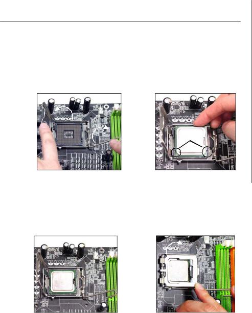
5.Lift the load lever up and open the load plate.
Hardware Setup
6.After confirming the CPU direction for correct mating, put down the CPU in the socket housing frame. Be sure to grasp on the edge of the CPU base. Note that the alignment keys are matched.
alignment key
7.Visually inspect if the CPU is seated well into the socket. If not, take out the CPU with pure vertical motion and reinstall.
8.Cover the load plate onto the package.
2-5
MS-7365 Mainboard
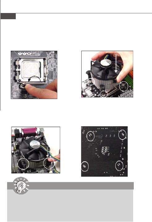
9.Press down the load lever lightly onto the load plate, and then secure the lever with the hook under retention tab.
11.Press the four hooks down to fasten the cooler. Then rotate the locking switch (refer to the correct direction marked on it) to lock the hooks.
locking switch
10.Align the holes on the mainboard with the heatsink. Push down the cooler until its four c lips get wedged into the holes of the mainboard.
12.Turn over the mainboard to confirm that the clip-ends are correctly inserted.
Important
1.Read the CPU status in BIOS (Chapter 3).
2.Whenever CPU is not installed, always protect your CPU socket pin with the plastic cap covered (shown in Figure 1) to avoid damaging.
3.Mainboard photos shown in this section are for demonstration of the CPU/ cooler installation only. The appearance of your mainboard may vary depending on the model you purchase.
2-6
![]()
Hardware Setup
Memory
These DIMM slots are used for installing memory modules.
Since DDR3 modules are not interchangeable with DDR2 and the DDR3 standard is not backward compatible, you should always install DDR3 memory module in DDR3 slot (DIMM_A1 & DIMM_B1), and DDR2 memory module in DDR2 slot (DIMM_A2 & DIMM_B2). Wrong installation may cause damage of mainboard. Meanwhile, you are not able to boot up your system if you install DDR2 & DDR3 memory modules simultaneously.
For more information on compatible components, please visit http://www.msi.com. tw/testreport.htm
DDR2
240-pin, 1.8V 
 56×2=112 pin 64×2=128 pin
DIMM_A2 & DIMM_B2 are for DDR2 memory module
Dual-Channel: Channel A in GREEN; Channel B in ORANGE
DDR3
240-pin, 1.5V
DIMM_A1 & DIMM_B1 are for DDR3 memory module
Dual-Channel: Channel A in SKYBLUE; Channel B in PINK
Dual-Channel mode Population Rule
In Dual-Channel mode, the memory modules can transmit and receive data with two data bus lines simultaneously. Enabling Dual-Channel mode can enhance the system performance. Please refer to the following illustrations for population rules under Dual-Channel mode.
1  DIMM_A1
  DIMM_A2
 DIMM_B1
  DIMM_B2
D u a l c h a n n e l m o d e population rule for DDR3
 DIMM_B1
  DIMM_B2
2-7
MS-7365 Mainboard
Installing Memory Modules
1.The memory module has only one notch on the center and will only fit in the right orientation.
2.Insert the memory module vertically into the DIMM slot. Then push it in until the golden finger on the memory module is deeply inserted in the DIMM slot.
Important
You can barely see the golden finger if the memory module is properly inserted in the DIMM slot.
3. The plastic clip at each side of the DIMM slot will automatically close.
Volt Notch
Important
—In Dual-Channel mode, make sure that you install memory modules of the same type and density in different channel DIMM slots.
—To enable successful system boot-up, always insert the memory modules into the DIMM_A1 or DIMM_A2 first.
—Due to the chipset resource deployment, the system density will only be detected up to 3+GB (not full 4GB) when each DIMM is installed with a 2GB memory module.
2-8

Hardware Setup
Power Supply
ATX 24-Pin Power Connector: JPWR3
This connector allows you to connect an ATX 24-pin power supply. To connect the ATX 24-pin power supply, make sure the plug of the power supply is inserted in the proper orientation and the pins are aligned. Then push down the power supply firmly into the connector.
You may use the 20-pin ATX power supply as you like. If you’d like to use the 20-pin ATX power supply, please plug your power supply along with pin 1 & pin 13 (refer to the image at the right hand). There is also a foolproof design on pin 11, 12, 23 & 24 to avoid wrong installation.
Pin Definition
 pin 13
 pin 12
|
12 |
24 |
PIN |
SIGNAL |
PIN |
SIGNAL |
|
|
1 |
+3.3V |
13 |
+3.3V |
|||
|
2 |
+3.3V |
14 |
-12V |
|||
|
3 |
GND |
15 |
GND |
|||
|
JPWR3 |
4 |
+5V |
16 |
PS-ON# |
||
|
5 |
GND |
17 |
GND |
|||
|
6 |
+5V |
18 |
GND |
|||
|
7 |
GND |
19 |
GND |
|||
|
8 |
PWROK |
20 |
Res |
|||
|
9 |
5VSB |
21 |
+5V |
|||
|
10 |
+12V |
22 |
+5V |
|||
|
1 |
13 |
11 |
+12V |
23 |
+5V |
|
|
12 |
+3.3V |
24 |
GND |
|||
ATX 12V Power Connector: JPW1
This 12V power connector JPW1 is used to provide power to the CPU.
Pin Definition
|
3 |
4 |
PIN |
SIGNAL |
|
1 |
2 |
1 |
GND |
|
JPW1 |
2 |
GND |
|
|
3 |
12V |
||
|
4 |
12V |
Important
1.Maker sure that all the connectors are connected to proper ATX power supplies to ensure stable operation of the mainboard.
2.Power supply of 350 watts (and above) is highly recommended for system stability.
2-9
MS-7365 Mainboard
Back Panel
|
Mouse |
Parallel Port |
(optional) |
LAN |
||
|
1394 Port |
|||||
|
Line-In RS-Out |
|||||
|
Line-Out CS-Out |
|||||
|
Keyboard |
Serial Port |
VGAPort |
USB Ports |
Mic SS-Out |
|
(optional)
 Mouse/Keyboard Connector
The standard PS/2® mouse/keyboard DIN connector is for a PS/2® mouse/keyboard.
 Parallel Port Connector
A parallel port is a standard printer port that supports Enhanced Parallel Port (EPP) and Extended Capabilities Parallel Port (ECP) mode.
 Serial Port
The serial port is a 16550A high speed communications port that sends/ receives 16 bytes FIFOs. You can attach a serial mouse or other serial devices directly to the connector.
 VGA Port (for G33 Neo Combo Series)
The DB15-pin female connector is provided for monitor.
 1394 Port (optional)
The IEEE1394 port on the back panel provides connection to IEEE1394 devices.
 USB Port
The USB (Universal Serial Bus) port is for attaching USB devices such as keyboard, mouse, or other USB-compatible devices.
2-10
Hardware Setup
 LAN (RJ-45) Jack
The standard RJ-45 jack is for connection to single Local Area Network (LAN). You can connect a network cable to it.
|
ActivityIndicator |
LinkIndicator |
|
LED |
Color |
LED State |
condition |
|
Off |
LAN link is not established. |
||
|
Left |
Orange |
On (steady state) |
LAN link is established. |
|
On (brighter & pulsing) The computeris communicating with another computer on the LAN. |
|||
|
Green |
Off |
10 Mbit/sec data rate is selected. |
|
|
Right |
On |
100 Mbit/sec data rate is selected. |
|
|
Orange |
On |
1000 Mbit/sec data rate is selected. |
 Audio Ports
These audio connectors are used for audio devices. You can differentiate the color of the audio jacks for different audio sound effects.
Line-In (Blue) — Line In, is used for external CD player, tapeplayer or other audio devices.
Line-Out (Green) — Line Out, is a connector for speakers or headphones.
Mic (Pink) — Mic, is a connector for microphones.
RS-Out (Black) — Rear-Surround Out in 4/ 5.1/ 7.1 channel mode.
CS-Out (Orange) — Center/ Subwoofer Out in 5.1/ 7.1 channel mode. SS-Out (Gray) — Side-Surround Out 7.1 channel mode.
2-11
MS-7365 Mainboard
Connectors
Floppy Disk Drive Connector: FDD1
This connector supports 360KB, 720KB, 1.2MB, 1.44MB or 2.88MB floppy disk drive.
FDD1
IDE Connector: IDE1
This connector supports IDE hard disk drives, optical disk drives and other IDE devices.
Important
If you install two IDE devices on the same cable, you must configure the drives separately to master / slave mode by setting jumpers. Refer to IDE device’ s documentation supplied by the vendors for jumper setting instructions.
2-12
Hardware Setup
Serial ATA Connector: SATA1/ SATA2/ SATA3/ SATA4/ SATA5/ SATA6/ SATA7 (SATA5 & SATA6 are for ICH9R only, SATA7 is controlled by Marvell 88SE6111)
This connector is a high-speed Serial ATA interface port. Each connector can connect to one Serial ATA device.
SATA7
(optional)
SATA6 SATA4 SATA2
SATA5 SATA3 SATA1
*SATA5 & SATA6 are for ICH9R only.
Important
Please do not fold the Serial ATA cable into 90-degree angle. Otherwise, data loss may occur during transmission.
2-13
MS-7365 Mainboard
Fan Power Connectors: CPUFAN1, SYSFAN1, SYSFAN2
The fan power connectors support system cooling fan with +12V. When connecting the wire to the connectors, always note that the red wire is the positive and should be connected to the +12V; the black wire is Ground and should be connected to GND. If the mainboard has a System Hardware Monitor chipset on-board, you must use a specially designed fan with speed sensor to take advantage of the CPU fan control.
Control SENSOR +12V GND
CPUFAN1
|
SENSOR |
SENSOR |
||||||
|
+12V |
+12V |
||||||
|
GND |
GND |
||||||
|
SYSFAN1 |
SYSFAN2 |
Important
1.Please refer to the recommended CPU fans at processor’s official website or consult the vendors for proper CPU cooling fan.
2.Fan cooler set with 3 or 4 pins power connector are both available for CPUFAN1.
3.CPUFAN1 supports fan control. You can setup it in H/W Monitor of BIOS Setup. You can install Dual Core Center utility that will automatically control the CPU fan speed according to the actual CPU temperature.
Chassis Intrusion Switch Connector: JCI1
This connector connects to a 2-pin chassis switch. If the chassis is opened, the switch will be short. The system will record this status and show a warning message on the screen. To clear the warning, you must enter the BIOS utility and clear the record.
GND  2
2
CINTRU  1
1
JCI1
CD-In Connector: CD_IN1
This connector is provided for external audio input.
CD_IN1
R


 L
L
GND
2-14
 Loading…
Table of Contents for MSI P35 Neo series:
-
B-7 Realtek ALC888 Audio Raise the key Lower the key Remove the human voice Frequently Used Equalizer Setting Realtek recognizes the needs that you might have. By leveraging our long experience at audio field, Realtek HD Audio Sound Manager provides you certain optimized equal- izer settings that are frequently used for your quick enjoyment. [How to Use It] Other than the buttons “Pop” “Live” “Club” & “Rock” shown on the page, to pull down the arrow
-
MS-7360 Mainboard B-18 Information In this tab it provides some information about this HD Audio Configuration utility, including Audio Driver Version, DirectX Version, Audio Controller & Audio Codec. You may also select the language of this utility by choosing from the Language list. Also there is a selection Show icon in system tray. Switch it on and an icon will show in the system tray. Right-click on the icon and the Audio Accessories dialogue box will appear which provides several mul
-
2-16 MS-7360 Mainboard Front USB Connector: JUSB1 / JUSB2 / JUSB3 / JUSB4 This connector, compliant with Intel ® I/O Connectivity Design Guide, is ideal for con- necting high-speed USB interface peripherals such as USB HDD, digital cameras, MP3 players, printers, modems and the like. PIN SIGNAL PIN SIGNAL 1 VCC 2 VCC 3 USB0- 4 USB1- 5 USB0+ 6 USB1+ 7 GND 8 GND 9 Key (no pin) 10 USBOC Pin Definition Important Note that the pins o
-
A-9 Dual Core Center Temperature In the Temperature sub-menu, you can see temperature status of your system. On the underside, it shows the graphs of the temperatures. Only the curves of the item which the button is lit up with red color will be shown.
-
3-19 BIOS Setup Current CPU/ DRAM Frequency These items show the current clocks of CPU and Memory speed. Read-only. D.O.T Control D.O.T. (Dynamic Overclocking Technology) is the automatic overclocking function, included in the MSI TM ’s newly developed CoreCell TM Technology. It is designed to detect the load balance of CPU while running programs, and to adjust the best CPU frequency automatically. When the mot
-
2-11 Hardware Setup LAN (RJ-45) Jack The standard RJ-45 jack is for connection to single Local Area Network (LAN). You can connect a network cable to it. Audio Ports These audio connectors are used for audio devices. You can differentiate the color of the audio jacks for different audio sound effects. Line-In (Blue) — Line In, is used for external CD player, tapeplayer or other audio devices. Line-Out (Green) — Line Out, is a connector for speakers or headphones.
-
B-3 Realtek ALC888 Audio 3. Click Next to install the Realtek High Definition Audio Driver. Click here Select this option 4. Click Finish to restart the system. Click here
-
2-19 Hardware Setup Jumpers Clear CMOS Jumper: JBAT1 There is a CMOS RAM onboard that has a power supply from an external battery to keep the data of system configuration. With the CMOS RAM, the system can auto- matically boot OS every time it is turned on. If you want to clear the system configuration, set the jumper to clear data. JBAT1 1 Clear Data 1 3 Keep Data 1 3 Important You can clear CMOS by shorting 2-3 pin while the system is off. Then return to 1-2 pin position. Avoid clea
-
vii
-
3-20 MS-7360 Mainboard [Sergeant] 2nd level of overclocking, increasing the frequency by 3%. [Captain] 3rd level of overclocking, increasing the frequency by 5%. [Colonel] 4th level of overclocking, increasing the frequency by 7%. [General] 5th level of overclocking, increasing the frequency by 10%. [Commander] 6th level of overclocking, increasing the frequency by 15%. Intel EIST The Enhanced Intel SpeedStep technology allows you to
-
3-9 BIOS Setup IOAPIC Function This field is used to enable or disable the APIC (Advanced Programmable Interrupt Controller). Due to compliance with PC2001 design guide, the system is able to run in APIC mode. Enabling APIC mode will expand available IRQ resources for the system. MPS Table Version This field allows you to select which MPS (Multi-Processor Specification) version to be used for the operating system. You need to sel
Questions, Opinions and Exploitation Impressions:
You can ask a question, express your opinion or share our experience of MSI P35 Neo series device using right now.