-
Contents
-
Table of Contents
-
Bookmarks
Quick Links
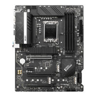
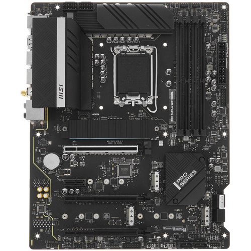
Thank you for purchasing the MSI®
PRO Z690-A DDR4
information about board layout, component overview, BIOS
setup and software installation.
Contents
Safety Information ………………………………………………………………………………. 3
Specifications ……………………………………………………………………………………… 4
Rear I/O Panel ………………………………………………………………………………….. 10
LAN Port LED Status Table …………………………………………………………………………..11
Audio Ports Configuration …………………………………………………………………………….11
Overview of Components …………………………………………………………………… 12
CPU Socket …………………………………………………………………………………………………13
DIMM Slots………………………………………………………………………………………………….14
DIMM Slots………………………………………………………………………………………………….14
M2_1~4: M.2 Slot (Key M) ……………………………………………………………………………..18
JUSB1~2: USB 2.0 Connectors ………………………………………………………………………20
JTPM1: TPM Module Connector …………………………………………………………………….22
JRGB1: RGB LED connector ………………………………………………………………………….25
EZ Debug LED ……………………………………………………………………………………………..25
Installing Windows® 10 …………………………………………………………………………………26
Installing Drivers …………………………………………………………………………………………26
MSI Center ………………………………………………………………………………………………….26
motherboard. This User Guide gives
PRO Z690-A WIFI DDR4/
1
Contents
Chapters
Summary of Contents for MSI PRO Z690-A WIFI DDR4
- Manuals
- Brands
- MSI Manuals
- Motherboard
- PRO Z690-A WIFI DDR4
Manuals and User Guides for MSI PRO Z690-A WIFI DDR4. We have 2 MSI PRO Z690-A WIFI DDR4 manuals available for free PDF download: Manual
MSI PRO Z690-A WIFI DDR4 Manual (249 pages)
Brand: MSI
|
Category: Motherboard
|
Size: 9.02 MB
Table of Contents
-
English
1
-
Table of Contents
1
-
Safety Information
3
-
Specifications
4
-
Rear I/O Panel
10
-
LAN Port LED Status Table
11
-
Audio Ports Configuration
11
-
Overview of Components
12
-
CPU Socket
13
-
DIMM Slots
14
-
PCI_E1~4: Pcie Expansion Slots
15
-
JFP1, JFP2: Front Panel Connectors
16
-
SATA1~6: SATA 6Gb/S Connectors
17
-
JAUD1: Front Audio Connector
17
-
M2_1~4: M.2 Slot (Key M)
18
-
ATX_PWR1, CPU_PWR1~2: Power Connectors
19
-
JUSB3~4: USB 3.2 Gen 1 5Gbps Connector
20
-
JUSB1~2: USB 2.0 Connectors
20
-
JUSB5: USB 3.2 Gen 2 Type-C Connector
21
-
JTBT1: Thunderbolt Add-On Card Connector
21
-
CPU_FAN1, PUMP_FAN1, SYS_FAN1~6: Fan Connectors
22
-
JTPM1: TPM Module Connector
22
-
JCI1: Chassis Intrusion Connector
23
-
JDASH1: Tuning Controller Connector
23
-
JRAINBOW1~2: Addressable RGB LED Connectors
24
-
JBAT1: Clear CMOS (Reset BIOS) Jumper
24
-
JRGB1: RGB LED Connector
25
-
EZ Debug LED
25
-
Installing OS, Drivers & MSI Center
26
-
Installing Windows® 10
26
-
Installing Drivers
26
-
MSI Center
26
-
Uefi Bios
27
-
BIOS User Guide
28
-
BIOS Setup
28
-
Entering BIOS Setup
28
-
Resetting BIOS
29
-
Updating BIOS
29
-
-
조선말/한국어
31
-
안전 지침
33
-
후면 I/O 패널
40
-
Lan 포트 Led 상태 표시
41
-
오디오 포트 구성 도표
41
-
구성품 개요
42
-
Cpu 소켓
43
-
DIMM 슬롯
44
-
PCI_E1~4: Pcie 확장 슬롯
45
-
Jfp1, Jfp2: 전면 패널 커넥터
46
-
SATA1~6: SATA 6Gb/S 커넥터
47
-
M2_1~4: M.2 슬롯 (Key M)
48
-
Atx_Pwr1, Cpu_Pwr1~2: 전원 커넥터
49
-
Jusb1~2: Usb 2.0 커넥터
50
-
JUSB3~4: USB 3.2 Gen 1 5Gbps 커넥터
50
-
Jtbt1: 썬더볼트 추가 카드 커넥터
51
-
JUSB5: USB 3.2 Gen 2 Type-C 커넥터
51
-
Cpu_Fan1, Pump_Fan1, Sys_Fan1~6: 팬 커넥터
52
-
Jtpm1: Tpm 모듈 커넥터
52
-
Jci1: 섀시 침입 커넥터
53
-
Jdash1: 튜닝 컨트롤러 커넥터
53
-
JBAT1: CMOS (Reset BIOS) 클리어 점퍼
54
-
Jrainbow1~2: 주소 지정 가능한 Rgb Led 커넥터
54
-
Ez 디버그 Led
55
-
Jrgb1: Rgb Led 커넥터
55
-
Msi 센터
56
-
Os, 드라이버 & 유틸리티 설치하기
56
-
Windows® 10설치하기
56
-
드라이버 설치하기
56
-
Uefi Bios
57
-
Bios (바이오스) 설정
58
-
Bios 설정
58
-
Bios 리셋
59
-
Bios(바이오스) 업데이트
59
-
-
Français
61
-
Informations de Sécurité
63
-
Spécifications
64
-
Panneau Arrière Entrée/Sortie
71
-
Configuration des Ports Audio
72
-
Tableau Explicatif de L’état de la LED du Port LAN
72
-
Vue D’ensemble des Composants
73
-
Socket Processeur
74
-
Slots DIMM
75
-
PCI_E1~4 : Slots D’extension Pcie
76
-
JFP1, JFP2 : Connecteurs de Panneau Avant
77
-
SATA1~6 : Connecteurs SATA 6 Gb/S
78
-
M2_1~4 : Slots M.2 (Touche M)
79
-
ATX_PWR1, CPU_PWR1~2 : Connecteurs D’alimentation
80
-
JUSB1~2 : Connecteurs USB 2.0
81
-
JUSB3~4 : Connecteurs USB 3.2 Gen 1 5 Gb/S
81
-
JTBT1 : Connecteur de Carte Additionnelle Thunderbolt
82
-
JUSB5 : Connecteur USB 3.2 Gen 2 Type-C
82
-
CPU_FAN1, PUMP_FAN1, SYS_FAN1~6 : Connecteurs de Ventilateur
83
-
JTPM1 : Connecteur de Module TPM
83
-
JCI1 : Connecteur Intrusion Châssis
84
-
JDASH1 : Connecteur du Contrôleur de Réglages
84
-
JBAT1 : Cavalier Clear CMOS (Réinitialiser Le BIOS)
85
-
JRAINBOW1~2 : Connecteurs LED RGB Adressables
85
-
EZ Debug LED
86
-
JRGB1 : Connecteur LED RGB
86
-
Installer Les Pilotes
87
-
Installer OS, Pilotes Et MSI Center
87
-
Installer Windows® 10
87
-
MSI Center
88
-
Uefi Bios
89
-
Configuration du BIOS
90
-
Entrer Dans la Configuration du BIOS
90
-
Guide D’utilisation du BIOS
90
-
Mettre Le BIOS À Jour
91
-
Réinitialiser Le BIOS
91
-
-
Deutsch
93
-
Sicherheitshinweis
95
-
Spezifikationen
96
-
Rückseite E/A
103
-
Konfiguration der Audioanschlüsse
104
-
LAN Port LED Zustandstabelle
104
-
Übersicht der Komponenten
105
-
CPU Sockel
106
-
DIMM Steckplätze
107
-
PCI_E1~4: Pcie Erweiterungssteckplätze
108
-
JFP1, JFP2: Frontpanel-Anschlüsse
109
-
SATA1~6: SATA 6Gb/S Anschlüsse
110
-
M2_1~4: M.2 Steckplatz (Key M)
111
-
ATX_PWR1, CPU_PWR1~2: Stromanschlüsse
112
-
JUSB1~2: USB 2.0 Anschlüsse
113
-
JUSB3~4: USB 3.2 Gen 1 5Gbit/S Anschluss
113
-
JTBT1: Anschluss für Thunderbolt-Erweiterungskarte
114
-
JUSB5: USB 3.2 Gen 2 Typ-C Anschluss
114
-
CPU_FAN1, PUMP_FAN1, SYS_FAN1~6: Stromanschlüsse für Lüfter
115
-
JTPM1: TPM Anschluss
115
-
JCI1: Gehäusekontaktanschluss
116
-
JDASH1: Tuning Controller-Anschluss
116
-
JBAT1: Clear CMOS Steckbrücke (Reset BIOS)
117
-
JRAINBOW1~2: Adressierbarer RGB-LED-Streifen Anschlüsse
117
-
Ez Debug Led
118
-
JRGB1: RGB LED Anschluss
118
-
Installation von OS, Treibern & MSI Center
119
-
Installation von Treibern
119
-
Installation von Windows® 10
119
-
MSI Center
120
-
Uefi Bios
121
-
BIOS Setup
122
-
BIOS-Benutzerhandbuch
122
-
Öffnen des BIOS Setups
122
-
Aktualisierung des BIOS
123
-
Reset des BIOS
123
-
-
Русский
125
-
Безопасное Использование Продукции
127
-
Технические Характеристики
128
-
Задняя Панель Портов Ввода/ Вывода
134
-
Конфигурация Портов Аудио
135
-
Таблица Состояний Индикатора Порта LAN
135
-
Компоненты Материнской Платы
137
-
Процессорный Сокет
137
-
Слоты DIMM
138
-
PCI_E1~4: Слоты Расширения Pcie
139
-
JFP1, JFP2: Разъемы Передней Панели
140
-
SATA1~6: Разъемы SATA 6Гб/С
141
-
M2_1~4: Разъемы M.2 (Ключ M)
142
-
ATX_PWR1, CPU_PWR1~2: Разъемы Питания
143
-
JUSB1~2: Разъемы USB 2.0
144
-
JUSB3~4: Разъем USB 3.2 Gen 1 5Гб/С
144
-
JTBT1: Разъем Для Установки Карты Расширения Thunderbolt
145
-
JUSB5: Разъем USB 3.2 Gen 2 Type-C
145
-
CPU_FAN1, PUMP_FAN1, SYS_FAN1~6: Разъемы Вентиляторов
146
-
JTPM1: Разъем Модуля ТРМ
146
-
JCI1: Разъем Датчика Открытия Корпуса
147
-
JDASH1: Разъем Контроллера Настройки
147
-
JBAT1: Джампер Очистки Данных CMOS (Сброс BIOS)
148
-
JRAINBOW1~2: Разъемы Адресных RGB LED
148
-
JRGB1: Разъем RGB LED
149
-
Индикаторы Отладки EZ
149
-
MSI Center
150
-
Установка Windows® 10
150
-
Установка Драйверов
150
-
Установка ОС, Драйверов И MSI Center
150
-
Uefi Bios
151
-
Вход В Настройки BIOS
152
-
Инструкции По Настройке BIOS
152
-
Настройка BIOS
152
-
Обновление BIOS
153
-
Сброс BIOS
153
-
-
汉语
155
-
安全信息
157
-
后置 I/O 面板
164
-
Lan 端口 Led 状态表
165
-
音频端口配置
165
-
组件概述
166
-
Cpu 底座
167
-
DIMM 插槽
168
-
PCI_E1~4: Pcie 扩展插槽
169
-
Jfp1, Jfp2: 前置面板接口
170
-
SATA1~6: SATA 6Gb/S 接口
171
-
M2_1~4: M.2 接口 (M 键)
172
-
Atx_Pwr1, Cpu_Pwr1~2: 电源接口
173
-
Jusb1~2: Usb 2.0 接口
174
-
JUSB3~4: USB 3.2 Gen 1 5Gbps 接口
174
-
JTBT1: Thunderbolt 附加卡接口
175
-
JUSB5: USB 3.2 Gen 2 Type-C 接口
175
-
Cpu_Fan1, Pump_Fan1, Sys_Fan1~6: 风扇接口
176
-
Jtpm1: Tpm 模组接口
176
-
Jci1: 机箱入侵检测接口
177
-
Jdash1: 调试控制器接口
177
-
Jbat1: 清除 Cmos (重启 Bios) 跳线
178
-
Jrainbow1~2: 寻址 Rgb Led 接口
178
-
Jrgb1: Rgb Led 接口
179
-
简易侦错 Led 灯
179
-
MSI Center
180
-
安装操作系统, 驱动程序和 MSI Center
180
-
安装驱动
180
-
Uefi Bios
181
-
Bios 用户指南
182
-
Bios 设置
182
-
进入 Bios 设置
182
-
更新 Bios
183
-
重启 Bios
183
-
-
漢語
185
-
背板 I/O
194
-
網路連接埠 Led 燈狀態表
195
-
音效連接埠設置
195
-
元件總覽
196
-
Cpu 腳座
197
-
記憶體插槽
198
-
PCI_E1~4: Pcie 擴充插槽
199
-
Jfp1, Jfp2: 系統面板接頭
200
-
Jaud1: 前置音效插孔
201
-
M2_1~4: M.2 插槽 (M 鍵)
202
-
Jci1: 機殼開啟接頭
207
-
Jdash1: 調試控制器接頭
207
-
Jbat1: 清除 Cmos (重置 Bios) 功能跳線
208
-
Jrainbow1~2: 可定址 Rgb Led 接頭
208
-
Jrgb1: Rgb Led 接頭
209
-
除錯 Led 指示燈
209
-
MSI Center
210
-
安裝操作系統 、 驅動程式和 MSI Center
210
-
安裝驅動程式
210
-
Uefi Bios
211
-
Bios 使用者指南
212
-
進入 Bios 設定
212
-
更新 Bios
213
-
重設 Bios
213
-
-
日本語
215
-
安全に関する注意事項
217
-
リアI/Oパネル
224
-
LanポートLed状態表
225
-
オーディオポートの配置
225
-
コンポーネントの概要
226
-
Cpuソケット
227
-
DIMMスロット
228
-
PCI_E1~4: Pcie拡張スロット
229
-
Jfp1、 Jfp2: フロントパネルコネクター
230
-
M2_1~4: M.2スロット (Key M)
232
-
Atx_Pwr1、 Cpu_Pwr1~2: 電源コネクター
233
-
Jusb1~2: Usb 2.0コネクター
234
-
JUSB3~4: USB 3.2 Gen 1 5Gbps コネクター
234
-
JTBT1: Thunderbolt追加カードコネクター
235
-
JUSB5: USB 3.2 Gen 2 Type-Cコネクター
235
-
Cpu_Fan1、 Pump_Fan1、 Sys_Fan1~6: ファンコネクター
236
-
Jtpm1: Tpmモジュールコネクター
236
-
Jci1: ケース開放スイッチコネクター
237
-
Jdash1: チューニングコントローラーコネクター
237
-
Jbat1: クリアCmos (Biosリセット) ジャンパ
238
-
Jrainbow1~2: 追加のRgb Ledコネクター
238
-
EZ Debug LED
239
-
Jrgb1: Rgb Ledコネクター
239
-
MSI Center
240
-
OS、 ドライバーおよびMSI Centerのインストール
240
-
Windows® 10のインストール
240
-
Uefi Bios
241
-
Biosの設定
242
-
Biosセットアップ画面の起動
242
-
Biosユーザーズガイド
242
-
Biosのアップデート方法
243
-
Biosのリセット
243
-
Advertisement

MSI PRO Z690-A WIFI DDR4 Manual (249 pages)
Brand: MSI
|
Category: Motherboard
|
Size: 9.12 MB
Table of Contents
-
Safety Information
3
-
Table of Contents
1
-
Specifications
4
-
Rear I/O Panel
10
-
LAN Port LED Status Table
11
-
Audio Ports Configuration
11
-
Overview of Components
12
-
CPU Socket
13
-
DIMM Slots
14
-
PCI_E1~4: Pcie Expansion Slots
15
-
JFP1, JFP2: Front Panel Connectors
16
-
SATA1~6: SATA 6Gb/S Connectors
17
-
JAUD1: Front Audio Connector
17
-
M2_1~4: M.2 Slot (Key M)
18
-
ATX_PWR1, CPU_PWR1~2: Power Connectors
19
-
JUSB1~2: USB 2.0 Connectors
20
-
JUSB3~4: USB 3.2 Gen 1 5Gbps Connector
20
-
JUSB5: USB 3.2 Gen 2 Type-C Connector
21
-
JTBT1: Thunderbolt Add-On Card Connector
21
-
CPU_FAN1, PUMP_FAN1, SYS_FAN1~6: Fan Connectors
22
-
JTPM1: TPM Module Connector
22
-
JCI1: Chassis Intrusion Connector
23
-
JDASH1: Tuning Controller Connector
23
-
JBAT1: Clear CMOS (Reset BIOS) Jumper
24
-
JRAINBOW1~2: Addressable RGB LED Connectors
24
-
JRGB1: RGB LED Connector
25
-
EZ Debug LED
25
-
Installing OS, Drivers & MSI Center
26
-
Installing Windows 10/ Windows 11
26
-
Installing Drivers
26
-
MSI Center
26
-
Uefi Bios
27
-
BIOS Setup
28
-
Entering BIOS Setup
28
-
BIOS User Guide
28
-
Resetting BIOS
29
-
Updating BIOS
29
-
안전 지침
33
-
후면 I/O 패널
40
-
Lan 포트 Led 상태 표시
41
-
오디오 포트 구성 도표
41
-
구성품 개요
42
-
Cpu 소켓
43
-
DIMM 슬롯
44
-
PCI_E1~4: Pcie 확장 슬롯
45
-
Jfp1, Jfp2: 전면 패널 커넥터
46
-
SATA1~6: SATA 6Gb/S 커넥터
47
-
M2_1~4: M.2 슬롯 (Key M)
48
-
Atx_Pwr1, Cpu_Pwr1~2: 전원 커넥터
49
-
Jusb1~2: Usb 2.0 커넥터
50
-
JUSB3~4: USB 3.2 Gen 1 5Gbps 커넥터
50
-
JUSB5: USB 3.2 Gen 2 Type-C 커넥터
51
-
Jtbt1: 썬더볼트 추가 카드 커넥터
51
-
Cpu_Fan1, Pump_Fan1, Sys_Fan1~6: 팬 커넥터
52
-
Jtpm1: Tpm 모듈 커넥터
52
-
Jci1: 섀시 침입 커넥터
53
-
Jdash1: 튜닝 컨트롤러 커넥터
53
-
JBAT1: CMOS (Reset BIOS) 클리어 점퍼
54
-
Jrainbow1~2: 주소 지정 가능한 Rgb Led 커넥터
54
-
Jrgb1: Rgb Led 커넥터
55
-
Ez 디버그 Led
55
-
Os, 드라이버 & Msi 센터 설치하기
56
-
Windows 10/ Windows 11 설치하기
56
-
드라이버 설치하기
56
-
Msi 센터
56
-
Uefi Bios
57
-
Bios (바이오스) 설정
58
-
Bios 설정
58
-
Bios 리셋
59
-
Bios(바이오스) 업데이트
59
-
Informations De Sécurité
63
-
Spécifications
64
-
Panneau Arrière Entrée/Sortie
70
-
Tableau Explicatif De L’état De La LED Du Port LAN
71
-
Configuration Des Ports Audio
71
-
Vue D’ensemble Des Composants
72
-
Socket Processeur
73
-
Slots DIMM
74
-
PCI_E1~4 : Slots D’extension Pcie
75
-
JFP1, JFP2 : Connecteurs De Panneau Avant
76
-
SATA1~6 : Connecteurs SATA 6 Gb/S
77
-
M2_1~4 : Slots M.2 (Touche M)
78
-
ATX_PWR1, CPU_PWR1~2 : Connecteurs D’alimentation
79
-
JUSB1~2 : Connecteurs USB 2.0
80
-
JUSB3~4 : Connecteurs USB 3.2 Gen 1 5 Gb/S
80
-
JUSB5 : Connecteur USB 3.2 Gen 2 Type-C
81
-
JTBT1 : Connecteur De Carte Additionnelle Thunderbolt
81
-
CPU_FAN1, PUMP_FAN1, SYS_FAN1~6 : Connecteurs De Ventilateur
82
-
JTPM1: Connecteur De Module TPM
82
-
JCI1 : Connecteur Intrusion Châssis
83
-
JDASH1 : Connecteur Du Contrôleur De Réglages
83
-
JBAT1 : Cavalier Clear CMOS (Réinitialiser Le BIOS)
84
-
JRAINBOW1~2 : Connecteurs LED RGB Adressables
84
-
JRGB1 : Connecteur LED RGB
85
-
EZ Debug LED
85
-
Installer OS, Pilotes Et MSI Center
86
-
Installer Windows 10/Windows 11
86
-
Installer Les Pilotes
86
-
MSI Center
87
-
Uefi Bios
88
-
Configuration Du BIOS
89
-
Entrer Dans La Configuration Du BIOS
89
-
Guide D’utilisation Du BIOS
89
-
Réinitialiser Le BIOS
90
-
Mettre Le BIOS À Jour
90
-
Sicherheitshinweis
95
-
Spezifikationen
96
-
Rückseite E/A
102
-
LAN Port LED Zustandstabelle
103
-
Konfiguration Der Audioanschlüsse
103
-
Übersicht Der Komponenten
104
-
CPU Sockel
105
-
DIMM Steckplätze
106
-
PCI_E1~4: Pcie Erweiterungssteckplätze
107
-
JFP1, JFP2: Frontpanel-Anschlüsse
108
-
SATA1~6: SATA 6Gb/S Anschlüsse
109
-
M2_1~4: M.2 Steckplatz (Key M)
110
-
ATX_PWR1, CPU_PWR1~2: Stromanschlüsse
111
-
JUSB1~2: USB 2.0 Anschlüsse
112
-
JUSB3~4: USB 3.2 Gen 1 5Gbit/S Anschluss
112
-
JUSB5: USB 3.2 Gen 2 Typ-C Anschluss
113
-
JTBT1: Anschluss Für Thunderbolt-Erweiterungskarte
113
-
CPU_FAN1, PUMP_FAN1, SYS_FAN1~6: Stromanschlüsse Für Lüfter
114
-
JTPM1: TPM Anschluss
114
-
JCI1: Gehäusekontaktanschluss
115
-
JDASH1: Tuning Controller-Anschluss
115
-
JBAT1: Clear CMOS Steckbrücke (Reset BIOS)
116
-
JRAINBOW1~2: Adressierbarer RGB-LED-Streifen Anschlüsse
116
-
JRGB1: RGB LED Anschluss
117
-
Ez Debug Led
117
-
Installation Von OS, Treibern & MSI Center
118
-
Installation Von Windows 10/ Windows 11
118
-
Installation Von Treibern
118
-
MSI Center
119
-
Uefi Bios
120
-
BIOS Setup
121
-
Öffnen Des BIOS Setups
121
-
BIOS-Benutzerhandbuch
121
-
Reset Des BIOS
122
-
Aktualisierung Des BIOS
122
-
Безопасное Использование Продукции
127
-
Технические Характеристики
128
-
Задняя Панель Портов Ввода/ Вывода
134
-
Таблица Состояний Индикатора Порта LAN
135
-
Конфигурация Портов Аудио
135
-
Компоненты Материнской Платы
137
-
Процессорный Сокет
137
-
Слоты DIMM
138
-
PCI_E1~4: Слоты Расширения Pcie
139
-
JFP1, JFP2: Разъемы Передней Панели
140
-
SATA1~6: Разъемы SATA 6Гб/С
141
-
M2_1~4: Разъемы M.2 (Ключ M)
142
-
ATX_PWR1, CPU_PWR1~2: Разъемы Питания
143
-
JUSB1~2: Разъемы USB 2.0
144
-
JUSB3~4: Разъемы USB 3.2 Gen 1 5Гб/С
144
-
JUSB5: Разъем USB 3.2 Gen 2 Type-C
145
-
JTBT1: Разъем Для Установки Карты Расширения Thunderbolt
145
-
CPU_FAN1, PUMP_FAN1, SYS_FAN1~6: Разъемы Вентиляторов
146
-
JTPM1: Разъем Модуля ТРМ
146
-
JCI1: Разъем Датчика Открытия Корпуса
147
-
JDASH1: Разъем Контроллера Настройки
147
-
JBAT1: Джампер Очистки Данных CMOS (Сброс BIOS)
148
-
JRAINBOW1~2: Разъемы Адресных RGB LED
148
-
JRGB1: Разъем RGB LED
149
-
Индикаторы Отладки EZ
149
-
Установка ОС, Драйверов И MSI Center
150
-
Установка Windows 10/ Windows 11
150
-
Установка Драйверов
150
-
MSI Center
150
-
Uefi Bios
151
-
Настройка BIOS
152
-
Вход В Настройки BIOS
152
-
Инструкции По Настройке BIOS
152
-
Сброс BIOS
153
-
Обновление BIOS
153
-
安全信息
157
-
后置 I/O 面板
164
-
Lan 端口 Led 状态表
165
-
音频端口配置
165
-
组件概述
166
-
Cpu 底座
167
-
DIMM 插槽
168
-
PCI_E1~4: Pcie 扩展插槽
169
-
Jfp1, Jfp2: 前置面板接口
170
-
SATA1~6: SATA 6Gb/S 接口
171
-
M2_1~4: M.2 接口 (M 键)
172
-
Atx_Pwr1, Cpu_Pwr1~2: 电源接口
173
-
Jusb1~2: Usb 2.0 接口
174
-
JUSB3~4: USB 3.2 Gen 1 5Gbps 接口
174
-
JUSB5: USB 3.2 Gen 2 Type-C 接口
175
-
JTBT1: Thunderbolt 附加卡接口
175
-
Cpu_Fan1, Pump_Fan1, Sys_Fan1~6: 风扇接口
176
-
Jtpm1: Tpm 模组接口
176
-
Jci1: 机箱入侵检测接口
177
-
Jdash1: 调试控制器接口
177
-
Jbat1: 清除 Cmos (重启 Bios) 跳线
178
-
Jrainbow1~2: 寻址 Rgb Led 接口
178
-
Jrgb1: Rgb Led 接口
179
-
简易侦错 Led 灯
179
-
安装操作系统, 驱动程序和 MSI Center
180
-
安装 Windows 10/ Windows 11
180
-
安装驱动
180
-
MSI Center
180
-
Uefi Bios
181
-
Bios 设置
182
-
进入 Bios 设置
182
-
Bios 用户指南
182
-
重启 Bios
183
-
更新 Bios
183
-
背板 I/O
194
-
網路連接埠 Led 燈狀態表
195
-
音效連接埠設置
195
-
元件總覽
196
-
Cpu 腳座
197
-
記憶體插槽
198
-
PCI_E1~4: Pcie 擴充插槽
199
-
Jfp1, Jfp2: 系統面板接頭
200
-
SATA1~6: SATA 6Gb/S 插孔
201
-
M2_1~4: M.2 插槽 (M 鍵)
202
-
Atx_Pwr1 , Cpu_Pwr1~2: 電源接頭
203
-
Jusb1~2: Usb 2.0 接頭
204
-
JUSB3~4: USB 3.2 Gen 1 5Gbps 接頭
204
-
JUSB5: USB 3.2 Gen 2 Type-C 接頭
205
-
JTBT1: Thunderbolt 擴充卡接頭
205
-
Cpu_Fan1, Pump_Fan1, Sys_Fan1~6: 風扇電源接頭
206
-
Jtpm1: Tpm 模組接頭
206
-
Jci1: 機殼開啟接頭
207
-
Jdash1: 調試控制器接頭
207
-
Jbat1: 清除 Cmos (重置 Bios) 功能跳線
208
-
Jrainbow1~2: 可定址 Rgb Led 接頭
208
-
Jrgb1: Rgb Led 接頭
209
-
除錯 Led 指示燈
209
-
安裝操作系統 、 驅動程式和 MSI Center
210
-
安裝驅動程式
210
-
MSI Center
210
-
Uefi Bios
211
-
進入 Bios 設定
212
-
Bios 使用者指南
212
-
重設 Bios
213
-
更新 Bios
213
-
安全に関する注意事項
217
-
リアI/Oパネル
224
-
LanポートLed状態表
225
-
オーディオポートの配置
225
-
コンポーネントの概要
226
-
Cpuソケット
227
-
DIMMスロット
228
-
PCI_E1~4: Pcie拡張スロット
229
-
Jfp1、 Jfp2: フロントパネルコネクター
230
-
M2_1~4: M.2スロット (Key M)
232
-
JTBT1: Thunderbolt追加カードコネクター
235
-
Jtpm1: Tpmモジュールコネクター
236
-
Jci1: ケース開放スイッチコネクター
237
-
Jdash1: チューニングコントローラーコネクター
237
-
Jbat1: クリアCmos (Biosリセット) ジャンパ
238
-
Jrainbow1~2: 追加のRgb Ledコネクター
238
-
Jrgb1: Rgb Ledコネクター
239
-
EZ Debug LED
239
-
OS、 ドライバーおよびMSI Centerのインストール
240
-
Windows 10/ Windows 11のインストール
240
-
ドライバーのインストール
240
-
MSI Center
240
-
Uefi Bios
241
-
Biosの設定
242
-
Biosセットアップ画面の起動
242
-
Biosユーザーズガイド
242
-
Biosのリセット
243
-
Biosのアップデート方法
243
Advertisement
Related Products
-
MSI PRO Z690-A DDR4
-
MSI PRO Z690-A PRO
-
MSI PRO Z790-P WIFI DDR4
-
MSI PRO Z790-P DDR4
-
MSI PRO Z790-A WIFI
-
MSI X58 PRO MS-7522
-
MSI PRO B760M BOMBER DDR4
-
MSI PRO B650-P WIFI
-
MSI PRO B760M-G DDR4
-
MSI PRO X670-P WIFI
MSI Categories
Motherboard
![]()
Laptop
Video Card
![]()
Desktop
![]()
Monitor
More MSI Manuals
MSI Manuals and Guides:
The main types of MSI PRO Z690-A WIFI DDR4 instructions: user guide — rules of useing and characteristics, service manual — repair, diagnostics, maintenance, operation manual — description of the main functions of MSI PRO Z690-A WIFI DDR4 equipment, etc.
Most of the instructions, that you can see on the site are uploaded by our users. If you have available a manual or document for MSI PRO Z690-A WIFI DDR4, which is currently not on the site or present in a different language version, we ask you to upload your document on website, using the «uploading form» available to all registered users.
Материнская плата MSI PRO Z690-A WIFI DDR4
LGA 1700, Intel Z690, 4xDDR4-3200 МГц, 3xPCI-Ex16, 4xM.2, Standard-ATX
подробнее

191
Код товара: 4880519
MSI PRO Z690-A WIFI DDR4: List of Available Documents
Note for Owners:
Guidesimo.com webproject is not a service center of MSI trademark and does not carries out works for diagnosis and repair of faulty MSI PRO Z690-A WIFI DDR4 equipment. For quality services, please contact an official service center of MSI company. On our website you can read and download documentation for your MSI PRO Z690-A WIFI DDR4 device for free and familiarize yourself with the technical specifications of device.
More Motherboard Devices:
-
ASROCK ALIVENF5-VSTA
11111ASRock ALiveNF5-VSTA MotherboardEnglishEnglishEnglishEnglishEnglishCopyright Notice:Copyright Notice:Copyright Notice:Copyright Notice:Copyright Notice:No part of this installation guide may be reproduced, transcribed, transmitted, or trans-lated in any language, in any form or by any means, except duplication of documen-tation by the purchaser for backup purpose, without written consent of …
ALIVENF5-VSTA Motherboard, 192
-
MSI RS350
1 English Before Start This quick reference together with the EZ guide is used for providing you with the assistance when installing computer system. For detail information, please read the user manual. 1. Static electricity may cause damage to the integrated circuits on the motherboard. Before handling any motherboard outside of its protective packaging, ensure that there is no static elec …
RS350 Motherboard, 8
-
Gigabyte 6VA
6VA1TABLE OF CONTENTS1. INTRODUCTION1.1. PREFACE……………………………………………………………………………………………… 1-11.2. KEY FEATURES ……………………………………………………………………………………. 1-11.3. PERFORMANCE LIST……………………………………………………………………………. 1-21.4. BLO …
6VA Motherboard, 20
-
Texas Instruments bq76940
User’s GuideSLVU924B–March 2014–Revised April 2014bq76920 Evaluation Module User’s GuideThe bq76920EVM evaluation module (EVM) is a complete evaluation system for the bq76920, a 3-cell to5-cell Li-Ion battery analog front end (AFE) integrated circuit. The EVM consists of a bq76920 circuitmodule which is used for simple evaluation of the bq76920 functions. The circuit module includes …
bq76940 Motherboard, 34
-
SC&T X3
?QUICK STARTThe most aggressive preloaded diesel tune. Good for everday use, racing, economy but not recommended for any type of towing.Less power than Performance. moderate gain over stock, safe for light towing.Should be used when towing any significant load. Shifting is Towing centered.For Heavy Loads, Engine and Boost left stock, Trans Only tune. Exhaust brake to increase engine braking while …
X3 Motherboard, 2