I
Quick Start
Quick Start
Thank you for purchasing the MSI
®
X470 GAMING PRO motherboard.
This Quick Start section provides demonstration diagrams about
how to install your computer. Some of the installations also provide
video demonstrations. Please link to the URL to watch it with the web
browser on your phone or tablet. You may have even link to the URL
by scanning the QR code.
Kurzanleitung
Danke, dass Sie das MSI
®
X470 GAMING PRO Motherboard gewählt
haben. Dieser Abschnitt der Kurzanleitung bietet eine Demo zur
Installation Ihres Computers. Manche Installationen bieten auch
die Videodemonstrationen. Klicken Sie auf die URL, um diese
Videoanleitung mit Ihrem Browser auf Ihrem Handy oder Table
anzusehen. Oder scannen Sie auch den QR Code mit Ihrem Handy,
um die URL zu öffnen.
Présentation rapide
Merci d’avoir choisi la carte mère MSI
®
X470 GAMING PRO. Ce
manuel fournit une rapide présentation avec des illustrations
explicatives qui vous aideront à assembler votre ordinateur. Des
tutoriels vidéo sont disponibles pour certaines étapes. Cliquez sur
le lien fourni pour regarder la vidéo sur votre téléphone ou votre
tablette. Vous pouvez également accéder au lien en scannant le QR
code qui lui est associé.
Быстрый старт
Благодарим вас за покупку материнской платы MSI
®
X470
GAMING PRO. В этом разделе представлена информация,
которая поможет вам при сборке комьютера. Для некоторых
этапов сборки имеются видеоинструкции. Для просмотра
видео, необходимо открыть соответствующую ссылку в
веб—браузере на вашем телефоне или планшете. Вы также
можете выполнить переход по ссылке, путем сканирования
QR-кода.
-
Contents
-
Table of Contents
-
Bookmarks
Quick Links
Quick Start
Thank you for purchasing the MSI
motherboard. This Quick Start section provides demonstration
diagrams about how to install your computer. Some of the
installations also provide video demonstrations. Please link to the
URL to watch it with the web browser on your phone or tablet. You
may have even link to the URL by scanning the QR code.
クイ ックスタート
この度は MSI
X470 GAMING PRO MAX
®
ただき� 誠にありがとうございます 。 このクイックスタートにはPCの�み
立て��のデモンストレーション�を掲�しています� いく つかの�み立
て手順に付きましては� ��ビデオを提供しています� スマートフ ォンやタ
ブレッ ト�末のウェブブラウザで�書に��されたURLにアクセスしてご
�ください� QRコードをスキャンすることでもURLのリンク先をご�照頂
けます�
퀵 스타트
X470 GAMING PRO MAX
MSI
®
이 부분에서는 컴퓨터를 설치하는 방법에 대한 데모 다이어그램과 일부
데모 동영상을 제공하고 있습니다. 휴대전화 또는 태블릿의 웹 브라우저를
통하여 URL에 링크한 후 설치 동영상을 감상하시기 바랍니다. 또는 QR
코드를 스캔하여 URL에 링크할 수도 있습니다.
快速指引
感謝您購買 MSI
®
供您安裝電腦的示範圖解 , 亦提供部分組件的安裝示範影片 ; 請您以智
慧型手機或平板的瀏覽器連上 URL 網址進行觀看� ��可�掃描 QR
code 的方式����至�址 。
���门
�谢�购买 MSI
®
了�关�何�装计�机演�图� ��设�还提供了视频演�� 请使用�
的手机或平�电脑上的网页浏览器链�至网址观看� ��可��过扫�
QR码链�到URL�
메인보드를 선택해주셔서 감사합니다.
X470 GAMING PRO MAX
X470 GAMING PRO MAX
X470 GAMING PRO MAX
®
マザーボードをお買い上げい
主機板 。 本快速指引章節提
主�� 本���门部�提供
I
Quick Start
Chapters
Summary of Contents for MSI GAMING PRO MAX X470
- Manuals
- Brands
- MSI Manuals
- Motherboard
- GAMING PRO MAX X470
Manuals and User Guides for MSI GAMING PRO MAX X470. We have 1 MSI GAMING PRO MAX X470 manual available for free PDF download: Quick Start Manual
MSI GAMING PRO MAX X470 Quick Start Manual (196 pages)
Brand: MSI
|
Category: Motherboard
|
Size: 14.12 MB
Table of Contents
-
Safety Information
14
-
Table of Contents
13
-
Specifications
15
-
Rear I/O Panel
20
-
LAN Port LED Status Table
20
-
Audio Ports Configuration
20
-
Realtek HD Audio Manager
21
-
Overview of Components
23
-
CPU Socket
24
-
DIMM Slots
25
-
PCI_E1~6: Pcie Expansion Slots
26
-
M2_1~2: M.2 Slots (Key M)
28
-
SATA1~6: SATA 6Gb/S Connectors
29
-
JLPT1: Parallel Port Connector
29
-
CPU_PWR1, CPU_PWR2, ATX_PWR1: Power Connectors
30
-
JUSB1~2: USB 2.0 Connectors
31
-
JUSB3~4: USB 3.2 Gen1 Connectors
31
-
CPU_FAN1, PUMP_FAN1, SYS_FAN1~4: Fan Connectors
32
-
JAUD1: Front Audio Connector
33
-
JCI1: Chassis Intrusion Connector
33
-
JFP1, JFP2: Front Panel Connectors
34
-
JTPM1: TPM Module Connector
34
-
JCOM1: Serial Port Connector
35
-
JRGB1, JRGB2: RGB LED Connectors
35
-
JBAT1: Clear CMOS (Reset BIOS) Jumper
36
-
CLR_CMOS1: Clear CMOS Button
36
-
BIOS Setup
37
-
Entering BIOS Setup
37
-
Resetting BIOS
38
-
Updating BIOS
38
-
EZ Mode
39
-
Advanced Mode
41
-
OC Menu
42
-
Software Description
47
-
Installing Windows ® 10
47
-
Installing Drivers
47
-
Installing Utilities
47
-
に�する
50
-
リアI/Oパネル
56
-
LanポートLed状
56
-
オーディオポートの
56
-
Realtek HDオーディオマネージャー
57
-
Cpuソケット
60
-
DIMMスロット
61
-
PCI_E1~6: Pcie��スロット
62
-
M2_1~2: M.2スロット (Key M)
64
-
SATA1~6: SATA 6Gb/Sコネクター
65
-
Jlpt1: パラレルポートコネクター
65
-
Cpu_Pwr1� Cpu_Pwr2� Atx_Pwr1
66
-
Jusb1~2: Usb 2.0コネクター
67
-
Cpu_Fan1� Pump_Fan1� Sys_Fan1~4: ファンコネクター
68
-
Jaud1: フロントオーディオコネクター
69
-
Jci1: ケース開放スイッチコネクター
69
-
Jfp1� Jfp2: フロントパネルコネクター
70
-
Jtpm1: Tpmモジュールコネクター
70
-
Jcom1: シリアルポートコネクター
71
-
Jrgb1� Jrgb2: Rgb Ledコネクター
71
-
Jbat1: クリアCmos (Biosリセット) ジャンパ
72
-
Clr_Cmos1: クリアCmosボタン
72
-
Biosの
73
-
Biosセットアップ�面の�動
73
-
Biosのリセット
74
-
Biosのアップデート
74
-
アドバンストモード
77
-
Ocメニュー
78
-
ソフトウェアの解
83
-
ドライバーのインストール
83
-
Windows
83
-
10のインストール
83
-
ユーティリティのインストール
83
-
안전 지침
86
-
후면 I/O 패널
92
-
Lan 포트 Led 상태 표시
92
-
오디오 포트 구성 도표
92
-
Realtek HD 오디오 매니저
93
-
구성품 개요
95
-
Cpu 소켓
96
-
DIMM 슬롯
97
-
PCI_E1~6: Pcie 확장 슬롯
98
-
M2_1~2: M.2 슬롯 (Key M)
100
-
SATA1~6: SATA 6Gb/S 커넥터
101
-
Jlpt1: 패러렐 포트 커넥터
101
-
Cpu_Pwr1, Cpu_Pwr2, Atx_Pwr1: 전원 커넥터
102
-
Jusb1~2: Usb 2.0 커넥터
103
-
JUSB3~4: USB 3.2 Gen1 커넥터
103
-
Cpu_Fan1, Pump_Fan1, Sys_Fan1~4: 팬 커넥터
104
-
Jaud1: 전면 오디오 커넥터
105
-
Jci1: 섀시 침입 커넥터
105
-
Jfp1, Jfp2: 전면 패널 커넥터
106
-
Jtpm1: Tpm 모듈 커넥터
106
-
Jcom1: 시리얼 포트 커넥터
107
-
Jrgb1, Jrgb2: Rgb Led 커넥터
107
-
JBAT1: CMOS (Reset BIOS) 클리어 점퍼
108
-
Clr_Cmos1: 클리어 Cmos 버튼
108
-
Bios 설정
109
-
Bios(바이오스) 리셋
110
-
Bios(바이오스) 업데이트
110
-
Ez 모드
111
-
고급 모드
113
-
Oc 메뉴
114
-
소프트웨어 설명
119
-
드라이버 설치하기
119
-
10 설치하기
119
-
유틸리티 설치하기
119
-
安全說明
122
-
背板 I/O
128
-
網路連接埠 Led 燈狀態表
128
-
音效連接埠設置
128
-
Realtek HD 音效管理器
129
-
元件總覽
131
-
Cpu 腳座
132
-
記憶體插槽
133
-
PCI_E1~6: Pcie 擴充插槽
134
-
M2_1~2: M.2 插槽 (M 鍵)
136
-
SATA1~6: SATA 6Gb/S 插孔
137
-
Jlpt1: 平行埠接頭
137
-
Cpu_Pwr1, Cpu_Pwr2, Atx_Pwr1: 電源接頭
138
-
Jusb1~2: Usb 2.0 接頭
139
-
JUSB3~4: USB 3.2 Gen1 接頭
139
-
Cpu_Fan1, Pump_Fan1, Sys_Fan1~4: 風扇電源接頭
140
-
Jaud1: 前置音效插孔
141
-
Jci1: 機殼開啟接頭
141
-
Jfp1, Jfp2: 系統面板接頭
142
-
Jtpm1: Tpm 模組接頭
142
-
Jcom1: 序列埠接頭
143
-
Jrgb1, Jrgb2: Rgb Led 接頭
143
-
Jbat1: 清除 Cmos (重置 Bios) 功能跳線
144
-
Clr_Cmos1: 清除 Cmos 按鈕
144
-
Bios 設定
145
-
進入 Bios 設定
145
-
重設 Bios
146
-
更新 Bios
146
-
Ez 模式
147
-
進階模式
149
-
Oc 功能表
150
-
軟體說明
155
-
安裝 Windows
155
-
安裝驅動程式
155
-
安裝公用程式
155
-
安全信息
158
-
后置 I/O 面板
164
-
Lan 端口 Led 状态表
164
-
音频端口配置
164
-
Realtek 高清晰音频管理软件
165
-
组件概述
167
-
Cpu 底座
168
-
DIMM 插槽
169
-
M2_1~2: M.2 接口 (M 键)
172
-
Cpu_Fan1, Pump_Fan1, Sys_Fan1~4: 风扇接口
176
-
Jaud1: 前置音频接口
177
-
Jci1: 机箱入侵检测接口
177
-
Jcom1: 串行端头接口
179
-
Jrgb1, Jrgb2: Rgb Led 接口
179
-
Jbat1: 清除 Cmos (重启 Bios) 跳线
180
-
Clr_Cmos1: 清除 Cmos 按钮
180
-
Bios 设置
181
-
进� Bios 设置
181
-
重启 Bios
182
-
更� Bios
182
-
Ez �式
183
-
高级模式
185
-
Oc 菜单
186
-
�装驱动
191
-
装工具
191
Advertisement
Advertisement
Related Products
-
MSI 645E Max2 Series MS-6567
-
MSI MAG B460M BAZOOKA
-
MSI MAG B550M MORTAR WIFI
-
MSI MAG Z390 TOMAHAWK
-
MSI MAG B460M MORTAR
-
MSI MAG B560M MORTAR WIFI
-
MSI MAG A520M VECTOR WIFI
-
MSI MAG B365M MORTAR
-
MSI MAG X570S TORPEDO MAX
-
MSI MAG X570 TOMAHAWK WIFI
MSI Categories
Motherboard
![]()
Laptop
Video Card
![]()
Desktop
![]()
Monitor
More MSI Manuals
![]()
Unpacking
Thank you for buying the MSI® X470 GAMING PRO MAX motherboard. Check to make sure your motherboard box contains the following items. If something is missing, contact your dealer as soon as possible.
|
Motherboard User |
||||||||||||||||||||
|
Drivers & Utilities |
||||||||||||||||||||
|
Disc |
Guide |
|||||||||||||||||||
Motherboard
|
I/O Shield |
M.2 Screw x2 |
|
SATA Cable x2 |
|
Case Badge |
SATA Cable Labels |
Unpacking 1
Safety Information
yThe components included in this package are prone to damage from electrostatic discharge (ESD). Please adhere to the following instructions to ensure successful computer assembly.
yEnsure that all components are securely connected. Loose connections may cause the computer to not recognize a component or fail to start.
yHold the motherboard by the edges to avoid touching sensitive components.
yIt is recommended to wear an electrostatic discharge (ESD) wrist strap when handling the motherboard to prevent electrostatic damage. If an ESD wrist strap is not available, discharge yourself of static electricity by touching another metal object before handling the motherboard.
yStore the motherboard in an electrostatic shielding container or on an anti-static pad whenever the motherboard is not installed.
yBefore turning on the computer, ensure that there are no loose screws or metal components on the motherboard or anywhere within the computer case.
yDo not boot the computer before installation is completed. This could cause permanent damage to the components as well as injury to the user.
yIf you need help during any installation step, please consult a certified computer technician.
yAlways turn off the power supply and unplug the power cord from the power outlet before installing or removing any computer component.
yKeep this user guide for future reference.
yKeep this motherboard away from humidity.
yMake sure that your electrical outlet provides the same voltage as is indicated on the PSU, before connecting the PSU to the electrical outlet.
yPlace the power cord such a way that people can not step on it. Do not place anything over the power cord.
yAll cautions and warnings on the motherboard should be noted.
yIf any of the following situations arises, get the motherboard checked by service personnel:
Liquid has penetrated into the computer.
The motherboard has been exposed to moisture.
The motherboard does not work well or you can not get it work according to user guide.
The motherboard has been dropped and damaged.
The motherboard has obvious sign of breakage.
yDo not leave this motherboard in an environment above 60°C (140°F), it may damage the motherboard.
2 Safety Information
Quick Start
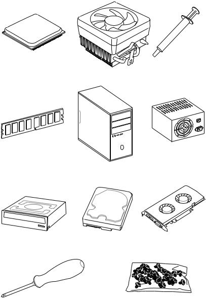
Preparing Tools and Components
AMD® AM4 CPU
Thermal Paste
CPU Fan
DDR4 Memory
Power Supply Unit
Chassis
|
SATA DVD Drive |
SATA Hard Disk Drive |
Graphics Card |
|
Phillips Screwdriver |
A Package of Screws |
Quick Start 3

Installing a Processor
|
1 |
|
3
2 
5
 4
4
|
6 |
8 |
9 |
|
|
7 |
CPU_FAN1 |
||
4 Quick Start
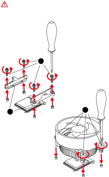
Important
If you are installing the screw-type CPU heatsink, please follow the figure below to remove the retention module first and then install the heatsink.
1
Quick Start 5
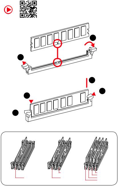
Installing DDR4 memory
1
1 
2
 3 2
3 2 


3 


|
DIMMB2 |
DIMMB2 |
|
|
DIMMB1 |
||
|
DIMMA2 |
DIMMA2 |
DIMMA2 |
|
DIMMA1 |
6 Quick Start
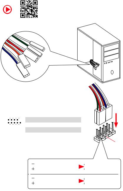
Connecting the Front Panel Header
|
— |
|||
|
LED |
|||
|
LED+ |
POWER |
||
|
POWER |
|||
|
LED |
|||
|
SW |
HDD |
||
|
POWER |
|||
|
SW |
|||
|
RESET |
|
2 |
10 |
1 |
HDD LED + |
2 |
Power LED + |
|||||
|
3 |
HDD LED — |
4 |
Power LED — |
|||||||
|
5 |
Reset Switch |
6 |
Power Switch |
|||||||
|
1 |
9 |
|||||||||
|
JFP1 |
7 |
Reset Switch |
8 |
Power Switch |
||||||
|
9 |
Reserved |
10 |
No Pin |
|||||||
|
HDD LED |
HDD LED — |
||||||
|
HDD LED + |
|||||||
|
POWER LED — |
|||||||
|
POWER LED |
POWER LED + |
||||||
Quick Start 7
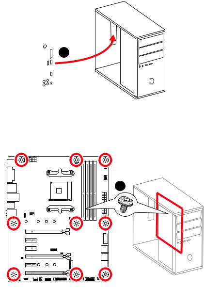
Installing the Motherboard
1
2
8 Quick Start
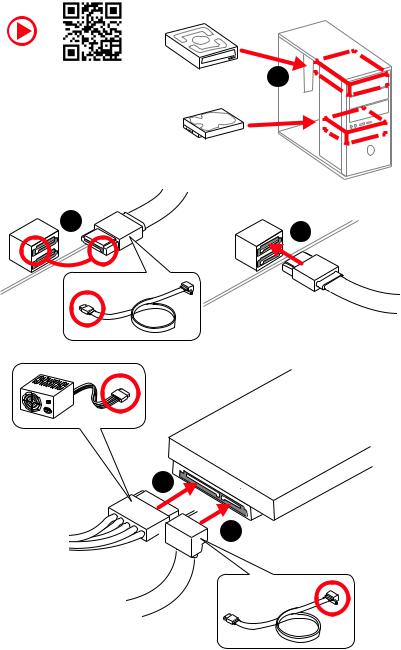
Installing SATA Drives
|
1 |
|
5
 4
4
Quick Start 9
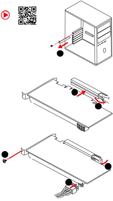
Installing a Graphics Card
1
3
2 
5
 4
4
6 

10 Quick Start
![]()
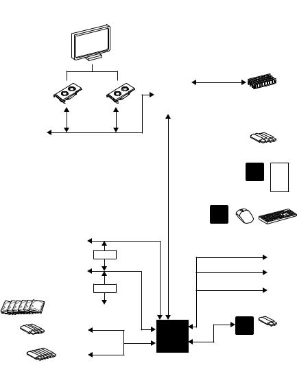
Connecting Peripheral Devices
|
Integrated |
Graphics |
|
|
Processing |
||
|
Unit |
||
|
(iGPU) |
Quick Start 11
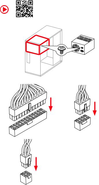
Connecting the Power Connectors
CPU_PWR2
12 Quick Start
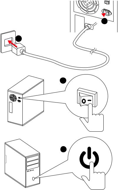
Power On
 1
1
2
3
4
Quick Start 13
|
Contents |
|
|
Unpacking……………………………………………………………………………………………….. |
1 |
|
Safety Information……………………………………………………………………………………. |
2 |
|
Quick Start ………………………………………………………………………………………………. |
3 |
|
Preparing Tools and Components……………………………………………………………….. |
3 |
|
Installing a Processor………………………………………………………………………………… |
4 |
|
Installing DDR4 memory ……………………………………………………………………………. |
6 |
|
Connecting the Front Panel Header…………………………………………………………….. |
7 |
|
Installing the Motherboard…………………………………………………………………………. |
8 |
|
Installing SATA Drives………………………………………………………………………………… |
9 |
|
Installing a Graphics Card ………………………………………………………………………… |
10 |
|
Connecting Peripheral Devices …………………………………………………………………. |
11 |
|
Connecting the Power Connectors…………………………………………………………….. |
12 |
|
Power On………………………………………………………………………………………………… |
13 |
|
Specifications…………………………………………………………………………………………. |
17 |
|
Block Diagram ………………………………………………………………………………………. |
22 |
|
Rear I/O Panel………………………………………………………………………………………… |
23 |
|
LAN Port LED Status Table……………………………………………………………………….. |
23 |
|
Audio Ports Configuration ………………………………………………………………………… |
23 |
|
Realtek HD Audio Manager ………………………………………………………………………. |
24 |
|
Overview of Components ………………………………………………………………………… |
26 |
|
CPU Socket …………………………………………………………………………………………….. |
28 |
|
DIMM Slots……………………………………………………………………………………………… |
29 |
|
PCI_E1~6: PCIe Expansion Slots……………………………………………………………….. |
30 |
|
M2_1~2: M.2 Slots (Key M) ……………………………………………………………………….. |
32 |
|
SATA1~6: SATA 6Gb/s Connectors …………………………………………………………….. |
33 |
|
JLPT1: Parallel Port Connector ………………………………………………………………… |
33 |
|
CPU_PWR1, CPU_PWR2, ATX_PWR1: Power Connectors ……………………………. |
34 |
|
JUSB1~2: USB 2.0 Connectors………………………………………………………………….. |
35 |
|
JUSB3~4: USB 3.2 Gen1 Connectors …………………………………………………………. |
35 |
|
CPU_FAN1, PUMP_FAN1, SYS_FAN1~4: Fan Connectors…………………………….. |
36 |
|
JAUD1: Front Audio Connector …………………………………………………………………. |
37 |
|
JCI1: Chassis Intrusion Connector…………………………………………………………….. |
37 |
|
JFP1, JFP2: Front Panel Connectors …………………………………………………………. |
38 |
|
JTPM1: TPM Module Connector………………………………………………………………… |
38 |
|
JCOM1: Serial Port Connector ………………………………………………………………….. |
39 |
|
JRGB1, JRGB2: RGB LED Connectors ……………………………………………………….. |
39 |
|
JBAT1: Clear CMOS (Reset BIOS) Jumper ………………………………………………….. |
40 |
14 Contents
|
CLR_CMOS1: Clear CMOS Button……………………………………………………………… |
40 |
|
BIOS Setup…………………………………………………………………………………………….. |
41 |
|
Entering BIOS Setup………………………………………………………………………………… |
41 |
|
Resetting BIOS………………………………………………………………………………………… |
42 |
|
Updating BIOS…………………………………………………………………………………………. |
42 |
|
EZ Mode …………………………………………………………………………………………………. |
43 |
|
Advanced Mode ………………………………………………………………………………………. |
45 |
|
SETTINGS……………………………………………………………………………………………….. |
46 |
|
Advanced………………………………………………………………………………………………… |
46 |
|
Boot……………………………………………………………………………………………………….. |
51 |
|
Security………………………………………………………………………………………………….. |
52 |
|
Save & Exit……………………………………………………………………………………………… |
54 |
|
OC………………………………………………………………………………………………………….. |
55 |
|
M-FLASH ……………………………………………………………………………………………….. |
60 |
|
OC PROFILE……………………………………………………………………………………………. |
61 |
|
HARDWARE MONITOR……………………………………………………………………………… |
62 |
|
A-XMP Operation …………………………………………………………………………………….. |
63 |
|
Software Description………………………………………………………………………………. |
64 |
|
Installing Windows® 10…………………………………………………………………………….. |
64 |
|
Installing Drivers …………………………………………………………………………………….. |
64 |
|
Installing Utilities ……………………………………………………………………………………. |
64 |
|
APP MANAGER ……………………………………………………………………………………….. |
65 |
|
LIVE UPDATE 6………………………………………………………………………………………… |
66 |
|
COMMAND CENTER ………………………………………………………………………………… |
68 |
|
GAMING APP…………………………………………………………………………………………… |
72 |
|
X-BOOST ………………………………………………………………………………………………… |
77 |
|
MYSTIC LIGHT…………………………………………………………………………………………. |
79 |
|
MYSTIC LIGHT PARTY ………………………………………………………………………………. |
83 |
|
Joining Group………………………………………………………………………………………….. |
84 |
|
Group Control Panel ………………………………………………………………………………… |
85 |
|
Inviting Member………………………………………………………………………………………. |
86 |
|
SMART TOOL…………………………………………………………………………………………… |
87 |
|
RAMDISK………………………………………………………………………………………………… |
89 |
|
Nahimic 2.5…………………………………………………………………………………………….. |
90 |
|
RAID Configuration…………………………………………………………………………………. |
95 |
|
Using AMD RAID Controller BIOS Configuration Utility………………………………… |
95 |
|
Initialize Disks ………………………………………………………………………………………… |
97 |
|
Create Arrays………………………………………………………………………………………….. |
98 |
|
Delete Arrays ………………………………………………………………………………………….. |
99 |
|
Swap Arrays………………………………………………………………………………………….. |
100 |
Contents 15
|
Manage Spares ……………………………………………………………………………………… |
101 |
|
Change the Controller Options………………………………………………………………… |
102 |
|
Booting the system from an array……………………………………………………………. |
102 |
|
Pausing the boot sequence for warning messages ……………………………………. |
102 |
|
Change the Staggered Spinup Count ……………………………………………………….. |
103 |
|
Using UEFI to create a 2.2TB RAID ………………………………………………………….. |
104 |
|
Installing RAID Driver…………………………………………………………………………….. |
105 |
|
Troubleshooting …………………………………………………………………………………… |
106 |
16 Contents

Specifications
|
Supports 1st, 2nd and 3rd Gen AMD Ryzen™/ Ryzen™ with |
||
|
CPU |
Radeon™ Vega Graphics and 2nd Gen AMD Ryzen™ with |
|
|
Radeon™ Graphics/ Athlon™ with Radeon™ Vega Graphics |
||
|
Desktop Processors for Socket AM4 |
||
|
Chipset |
AMD® X470 Chipset |
|
|
y4x DDR4 memory slots, support up to 64GB |
||
|
Supports DDR4 1866/ 2133/ 2400/ 2667 Mhz by JEDEC, |
||
|
and 2667/ 2800/ 2933/ 3000/ 3066/ 3200/ 3466 Mhz by |
||
|
A-XMP OC MODE* |
||
|
Memory |
yDual channel memory architecture |
|
|
ySupports non-ECC UDIMM memory |
||
|
ySupports ECC UDIMM memory |
||
|
* Athlon™ with Radeon™ Vega Graphics processors support up to 2400 MHz. And |
||
|
the supporting frequency of memory varies with installed processor. Please refer |
||
|
www.msi.com for more information on compatible memory. |
||
|
y2x PCIe 3.0 x16 slots (PCIE_1, PCIE_4) |
||
|
1st, 2nd and 3rd Gen AMD Ryzen™ Processors support |
||
|
x16/x0, x8/x8 mode |
||
|
Ryzen™ with Radeon™ Vega Graphics and 2nd Gen AMD |
||
|
Ryzen™ with Radeon™ Graphics Processors support x8/ |
||
|
Expansion Slots |
x0 mode |
|
|
Athlon™ with Radeon™ Vega Graphics Processors |
||
|
support x4/x0 mode |
||
|
y1x PCIe 2.0 x16 slot (PCIE_6, supports x4 mode)* |
||
|
y3x PCIe 2.0 x1 slots |
||
|
* PCI_E6 slot will be unavailable when installing M.2 PCIe SSD in M2_2 slot. |
||
|
y1x DVI-D port, supports a maximum resolution of |
||
|
1920×1200@60Hz* |
||
|
Onboard Graphics |
y1x HDMI™ port 1.4, supports a maximum resolution of |
|
|
4096×2160@30Hz* |
||
|
* Only support when using Radeon™ Vega Graphics and 2nd Gen AMD Ryzen™ |
||
|
with Radeon™ Graphics/ Athlon™ with Radeon™ Vega Graphics Processors |
||
|
* Maximum shared memory of 2048 MB |
||
|
Continued on next page |
Specifications 17

|
Continued from previous page |
||
|
y1st, 2nd and 3rd Gen AMD Ryzen™ Processors |
||
|
Supports 3-Way AMD® CrossFire™ Technology |
||
|
Multi-GPU |
yRyzen™ with Radeon™ Vega Graphics and 2nd Gen AMD |
|
|
Ryzen™ with Radeon™ Graphics/ Athlon™ with Radeon™ |
||
|
Vega Graphics Processors |
||
|
Supports 2-Way AMD® CrossFire™ Technology |
||
|
LAN |
1x Realtek® 8111H Gigabit LAN controller |
|
|
y6x SATA 6Gb/s ports (from AMD® X470 Chipset) |
||
|
y2x M.2 ports (Key M)* |
||
|
M2_1 slot (from AMD® processor) supports PCIe |
||
|
3.0×4 (1st, 2nd and 3rd Gen AMD Ryzen™/ Ryzen™ with |
||
|
Radeon™ Vega Graphics and 2nd Gen AMD Ryzen™ with |
||
|
Storage |
Radeon™ Graphics Processors) or PCIe 3.0×2 (Athlon™ |
|
|
with Radeon™ Vega Graphics Processors) 2242/ 2260 |
||
|
/2280/ 22110 storage devices |
||
|
M2_2 slot (from AMD® X470 Chipset) supports PCIe 2.0 |
||
|
x4 and SATA 6Gb/s 2242/ 2260 /2280 storage devices |
||
|
* SATA1 port will be unavailable when installing SATA M.2 SSD in M2_2 slot. |
||
|
* PCI_E6 slot will be unavailable when installing PCIe M.2 SSD in M2_2 slot. |
||
|
RAID |
AMD® X470 Chipset |
|
|
ySupports RAID 0, RAID 1 and RAID 10 for SATA storage |
||
|
devices |
||
|
yASMedia® ASM1143 Chipset |
||
|
2x USB 3.2 Gen2 (SuperSpeed USB 10Gbps) Type-A |
||
|
ports on the back panel |
||
|
yAMD® X470 Chipset |
||
|
4x USB 3.2 Gen1 (SuperSpeed USB) ports through the |
||
|
USB |
internal USB connectors |
|
|
6x USB 2.0 (High-speed USB) ports (2 Type-A ports on |
||
|
the back panel, 4 ports available through the internal |
||
|
USB connectors) |
||
|
yAMD® CPU |
||
|
4x USB 3.2 Gen1 (SuperSpeed USB) Type-A ports on the |
||
|
back panel |
||
|
Continued on next page |
18 Specifications

|
Continued from previous page |
||
|
yRealtek® ALC892 Codec |
||
|
Audio |
y7.1-Channel High Definition Audio |
|
|
ySupports S/PDIF output |
||
|
y1x PS/2 keyboard/ mouse combo port |
||
|
y2x USB 2.0 Type-A ports |
||
|
y1x DVI-D port |
||
|
Back Panel |
y1x HDMI™ 1.4 port |
|
|
y4x USB 3.2 Gen1 Type-A ports |
||
|
Connectors |
||
|
y1x LAN (RJ45) port |
||
|
y2x USB 3.2 Gen2 Type-A ports |
||
|
y5x OFC audio jacks |
||
|
y1x Optical S/PDIF OUT connector |
||
|
y1x 24-pin ATX main power connector |
||
|
y1x 8-pin ATX 12V power connector |
||
|
y1x 4-pin ATX 12V power connector |
||
|
y6x SATA 6Gb/s connectors |
||
|
y2x USB 2.0 connectors (support additional 4 USB 2.0 ports) |
||
|
y2x USB 3.2 Gen1 connectors (support additional 4 USB 3.2 |
||
|
Gen1 ports) |
||
|
y1x 4-pin CPU fan connector |
||
|
y1x 4-pin PUMP fan connector (supports up to 2A) |
Internal Connectors y4x 4-pin system fan connectors
y1x Serial port connector
y1x Parallel port connector
y2x 5050 RGB LED strip 12V connectors
y1x TPM module connector
y1x Front panel audio connector
y2x System panel connectors
y1x Chassis Intrusion connector
y1x Clear CMOS jumper
y1x Clear CMOS button
Continued on next page
Specifications 19

|
Continued from previous page |
||
|
I/O Controller |
NUVOTON NCT6795D Controller Chip |
|
|
yCPU/System temperature detection |
||
|
Hardware Monitor |
yCPU/System fan speed detection |
|
|
yCPU/System fan speed control |
||
|
Form Factor |
yATX Form Factor |
|
|
y12 in. x 9.6 in. (30.5 cm x 24.4 cm) |
||
|
y1x 256 Mb flash |
||
|
BIOS Features |
yUEFI AMI BIOS |
|
|
yACPI 6.1, SM BIOS 2.8 |
||
|
yMulti-language |
||
|
yDrivers |
||
|
yAPP MANAGER |
||
|
yCOMMAND CENTER |
||
|
yLIVE UPDATE 6 |
||
|
yMYSTIC LIGHT |
||
|
ySUPER CHARGER |
||
|
yGAMING APP |
||
|
Software |
yRAMDISK |
|
|
yX-BOOST |
||
|
ySMART TOOL |
||
|
yNahimic Audio |
||
|
yOpen Broadcaster Software (OBS) |
||
|
yNorton™ Internet Security Solution |
||
|
yGoogle Chrome™, Google Toolbar, Google Drive |
||
|
yCPU-Z MSI GAMING |
||
|
Continued on next page |
20 Specifications
Continued from previous page
|
yAudio |
||
|
Audio Boost |
||
|
Voice Boost |
||
|
Nahimic 2.5 |
||
|
yStorage |
||
|
Turbo M.2 |
||
|
yFan |
||
|
Pump Fan |
||
|
Smart Fan Control |
||
|
yLED |
||
|
Mystic Light |
||
|
Mystic Light Extension |
||
|
Mystic light SYNC |
||
|
EZ DEBUG LED |
||
|
yProtection |
||
|
Special Features |
PCI-E Steel Armor |
|
|
yPerformance |
||
|
Multi GPU-CrossFire Technology |
||
|
DDR4 Boost |
||
|
GAME Boost |
||
|
X-Boost |
||
|
A-XMP |
||
|
yStability |
||
|
7000+ Quality Test |
||
|
yVR |
||
|
VR Ready |
||
|
yGamer Experience |
||
|
RAMDisk |
||
|
yBIOS |
||
|
Click BIOS 5 |
||
|
yCertification |
||
|
GAMING Certified |
||
Specifications 21
Block Diagram
HDMI DVI-D
2 Channel DDR4 Memory
|
CPU |
|
|
1 x M.2 |
|
|
PCI Express Bus |
|
|
PCIex4 |
4 x USB 3.2 Gen1 |
|
Realtek |
|
|
ALC892 |
|
|
Audio Jacks |
|
NV6795 |
||||
|
Super I/O |
||||
|
P/S2 Mouse / Keyboard |
||||
|
PCIe x4 slot |
||||
|
Switch |
x1 |
PCIe x1 slot |
||
|
1 x M.2 |
x1 |
PCIe x1 slot |
||
|
Switch |
PCI |
x1 |
PCIe x1 slot |
|
|
6 x SATA 6Gb/s |
BusExpress |
|||
|
4 x USB 3.2 Gen1 |
X470 |
ASMEDIA |
2 x USB 3.2 Gen2 |
|
|
ASM1143 |
||||
|
6 x USB 2.0 |
||||
|
RTL8111H |
22 Block Diagram
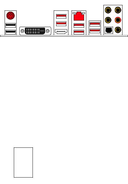
Rear I/O Panel
|
USB 3.2 Gen1 LAN |
Audio Ports |
|
|
PS/2 |
|
USB 2.0 |
USB 3.2 Gen2 |
|
|
USB 3.2 Gen1 |
Optical S/PDIF-Out |
LAN Port LED Status Table
Link/ Activity LED
|
Status |
Description |
|
Off |
No link |
|
Yellow |
Linked |
|
Blinking |
Data activity |
Speed LED
|
Status |
Description |
|
Off |
10 Mbps connection |
|
Green |
100 Mbps connection |
|
Orange |
1 Gbps connection |
Audio Ports Configuration
|
Audio Ports |
Channel |
||||
|
2 |
4 |
6 |
8 |
||
|
Center/ Subwoofer Out |
● |
● |
|||
|
Rear Speaker Out |
● |
● |
● |
||
|
Line-In/ Side Speaker Out |
● |
||||
|
Line-Out/ Front Speaker Out |
● |
● |
● |
● |
|
|
Mic In |
|||||
|
(●: connected, Blank: empty) |
Rear I/O Panel 23
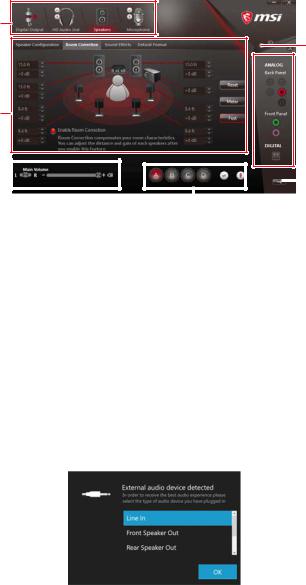
Realtek HD Audio Manager
After installing the Realtek HD Audio driver, the Realtek HD Audio Manager icon will appear in the system tray. Double click on the icon to launch.
Device
Selection
Advanced
Settings
 Jack Status
Application
Enhancement
|
Main Volume |
Connector |
||||||||
|
Settings |
|||||||||
|
Profiles |
|||||||||
yDevice Selection — allows you to select a audio output source to change the related options. The check sign indicates the devices as default.
yApplication Enhancement — the array of options will provide you a complete guidance of anticipated sound effect for both output and input device.
yMain Volume — controls the volume or balance the right/left side of the speakers that you plugged in front or rear panel by adjust the bar.
yProfiles — toggles between profiles.
yAdvanced Settings — provides the mechanism to deal with 2 independent audio streams.
yJack Status — depicts all render and capture devices currently connected with your computer.
yConnector Settings — configures the connection settings.
Auto popup dialog
When you plug into a device at an audio jack, a dialogue window will pop up asking you which device is current connected.
Each jack corresponds to its default setting as shown on the next page.
24 Rear I/O Panel
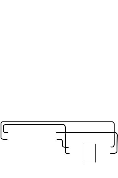
Audio jacks to headphone and microphone diagram
Audio jacks to stereo speakers diagram
AUDIO INPUT
Audio jacks to 7.1-channel speakers diagram
AUDIO INPUT
|
Rear |
Front |
|
Side |
Center/ |
|
Subwoofer |
Rear I/O Panel 25
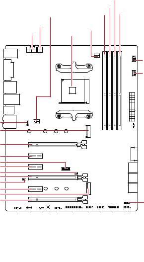
Overview of Components
JRGB2 M2_1
PCI_E1
PCI_E2
JTPM1 PCI_E3
JCI1 PCI_E4
JBAT1
PCI_E5
M2_2
PCI_E6
|
DIMMB1 |
||
|
DIMMA2 |
||
|
SYS_FAN1 |
DIMMA1 |
DIMMB2 |
|
CPU_PWR2 |
CPU_FAN1 |
|
|
CPU_PWR1 |
||
|
CPU Socket |
||
|
PUMP_FAN1 |
||
|
SYS_FAN3 |

 ATX_PWR1

 SYS_FAN4
 JUSB4
JUSB4
 SATA▼5▲6
 SATA▼3▲4
 SATA▼1▲2
JFP2
|
JAUD1 |
||||||||||||||||||||||||||||||||||||||||||||||||
|
JCOM1 |
||||||||||||||||||||||||||||||||||||||||||||||||
|
JRGB1 |
||||||||||||||||||||||||||||||||||||||||||||||||
|
JLPT1 |
JFP1 |
|||||||||||||||||||||||||||||||||||||||||||||||
|
SYS_FAN2 |
JUSB3 |
|||||||||||||||||||||||||||||||||||||||||||||||
|
Clear CMOS |
JUSB2 |
|||||||||||||||||||||||||||||||||||||||||||||||
|
JUSB1 |
26 Overview of Components
Component Contents
|
Port Name |
Port Type |
Page |
|
|
CLR_CMOS1 |
Clear CMOS Button |
40 |
|
|
CPU_FAN1, PUMP_FAN1, |
Fan Connectors |
36 |
|
|
SYS_FAN1~4 |
|||
|
CPU_PWR1, CPU_PWR2, |
Power Connectors |
34 |
|
|
ATX_PWR1 |
|||
|
CPU Socket |
AM4 CPU Socket |
28 |
|
|
DIMMA1, DIMMA2, |
DIMM Slots |
29 |
|
|
DIMMB1, DIMMB2 |
|||
|
JAUD1 |
Front Audio Connector |
37 |
|
|
JBAT1 |
Clear CMOS (Reset BIOS) Jumper |
40 |
|
|
JCI1 |
Chassis Intrusion Connector |
37 |
|
|
JCOM1 |
Serial Port Connector |
39 |
|
|
JFP1, JFP2 |
Front Panel Connectors |
38 |
|
|
JLPT1 |
Parallel Port Connector |
33 |
|
|
JRGB1, JRGB2 |
RGB LED Connectors |
39 |
|
|
JTPM1 |
TPM Module Connector |
38 |
|
|
JUSB1~2 |
USB 2.0 Connectors |
35 |
|
|
JUSB3~4 |
USB 3.2 Gen1 Connectors |
35 |
|
|
M2_1~2 |
M.2 Slots (Key M) |
32 |
|
|
PCI_E1~6 |
PCIe Expansion Slots |
30 |
|
|
SATA1~6 |
SATA 6Gb/s Connectors |
33 |
|
Overview of Components 27
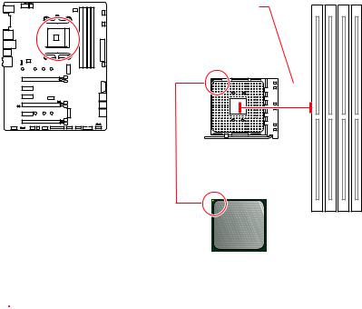
CPU Socket
Distance from the center of the
CPU to the nearest DIMM slot.
53.43 mm
Introduction to the AM4 CPU
The surface of the AM4 CPU has a yellow triangle to assist in correctly lining up the CPU for motherboard placement. The yellow triangle is the Pin 1 indicator.
 Important
yWhen changing the processor, the system configuration could be cleared and reset BIOS to default values, due to the AM4 processor’s architecture.
yAlways unplug the power cord from the power outlet before installing or removing the CPU.
yWhen installing a CPU, always remember to install a CPU heatsink. A CPU heatsink is necessary to prevent overheating and maintain system stability.
yConfirm that the CPU heatsink has formed a tight seal with the CPU before booting your system.
yOverheating can seriously damage the CPU and motherboard. Always make sure the cooling fans work properly to protect the CPU from overheating. Be sure to apply an even layer of thermal paste (or thermal tape) between the CPU and the heatsink to enhance heat dissipation.
yIf you purchased a separate CPU and heatsink/ cooler, Please refer to the documentation in the heatsink/ cooler package for more details about installation.
yThis motherboard is designed to support overclocking. Before attempting to overclock, please make sure that all other system components can tolerate overclocking. Any attempt to operate beyond product specifications is not recommended. MSI® does not guarantee the damages or risks caused by inadequate operation beyond product specifications.
28 Overview of Components
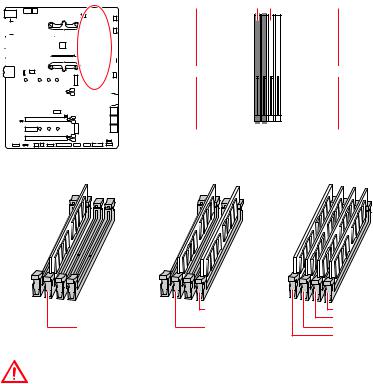
DIMM Slots
 DIMMA1
 DIMMB1
|
Channel A |
Channel B |
||||||||||||||||||||||||||||
 DIMMA2
 DIMMB2
Memory module installation recommendation
|
DIMMB2 |
DIMMB2 |
|
|
DIMMB1 |
||
|
DIMMA2 |
DIMMA2 |
DIMMA2 |
|
DIMMA1 |
Important
yAlways insert memory modules in the DIMMA2 slot first.
yDue to chipset resource usage, the available capacity of memory will be a little less than the amount of installed.
yBased on the processor specification, the Memory DIMM voltage below 1.35V is suggested to protect the processor.
ySome memory modules may operate at a lower frequency than the marked value when overclocking due to the memory frequency operates dependent on its Serial Presence Detect (SPD). Go to BIOS and find the DRAM Frequency to set the memory frequency if you want to operate the memory at the marked or at a higher frequency.
yIt is recommended to use a more efficient memory cooling system for full DIMMs installation or overclocking.
yThe stability and compatibility of installed memory module depend on installed CPU and devices when overclocking.
yDue to AM4 CPU/memory controller official specification limitation, the frequency of memory modules may operate lower than the marked value under the default state. Please refer www.msi.com for more information on compatible memory.
Overview of Components 29
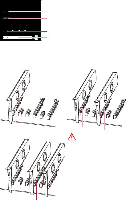
PCI_E1~6: PCIe Expansion Slots
 PCI_E1: PCIe 3.0 x16*/ PCIe 3.0 x8**/ PCIe 3.0 x4***
PCI_E2: PCIe 2.0 x1 PCI_E3: PCIe 2.0 x1

 PCI_E4: PCIe 3.0 x8*/ Unavailable**/ Unavailable***
PCI_E5: PCIe 2.0 x1 PCI_E6: PCIe 2.0 x4
*For 1st, 2nd and 3rd Gen AMD Ryzen™ Processors
**Ryzen™ with Radeon™ Vega Graphics and 2nd Gen AMD Ryzen™ with Radeon™ Graphics Processors
***Athlon™ with Radeon™ Vega Graphics Processors
Multiple graphics cards installation recommendation (Ryzen™ series processors)
Important
yIf you install a large and heavy graphics card, you need to use a tool such as MSI Gaming Series Graphics Card Bolster to support its weight to prevent deformation of the slot.
yFor a single PCIe x16 expansion card installation with optimum performance, using the PCI_E1 slot is recommended.
x8
yWhen adding or removing expansion
cards, always turn off the power supply
and unplug the power supply power
cable from the power outlet. Read the expansion card’s documentation to
check for any necessary additional hardware or software changes.
x8 x4
30 Overview of Components
![]()
PCIe bandwidth table
For 1st, 2nd and 3rd Gen AMD Ryzen™ Processors
|
Slot |
Single |
2-Way |
||||
|
PCI_E1 (CPU) |
Gen 3.0 x 16* |
Gen 3.0 x 8* |
||||
|
PCI_E2 (PCH) |
Gen 2.0 x 1 |
Gen 2.0 x 1 |
||||
|
PCI_E3 (PCH) |
Gen 2.0 x 1 |
Gen 2.0 x 1 |
||||
|
PCI_E4 (CPU) |
─ |
Gen 3.0 x 8* |
||||
|
PCI_E5 (PCH) |
Gen 2.0 x 1 |
Gen 2.0 x 1 |
||||
|
PCI_E6 (PCH) |
Gen 2.0 x 4 |
─ |
Gen 2.0 x 4 |
─ |
||
|
M2_1 (CPU) |
Gen 3.0 x 4 |
Gen 3.0 x 4 |
||||
|
M2_2 (PCH) |
─ |
Gen 2.0 x 4 |
─ |
Gen 2.0 x 4 |
||
|
(─: unavailable, *: graphics card) |
For Ryzen™ with Radeon™ Vega Graphics and 2nd Gen AMD Ryzen™ with Radeon™ Graphics Processors
|
Slot |
Single |
||
|
PCI_E1 (CPU) |
Gen 3.0 x 8* |
||
|
PCI_E2 (PCH) |
Gen 2.0 x 1 |
||
|
PCI_E3 (PCH) |
Gen 2.0 x 1 |
||
|
PCI_E4 (CPU) |
─ |
||
|
PCI_E5 (PCH) |
Gen 2.0 x 1 |
||
|
PCI_E6 (PCH) |
Gen 2.0 x 4 |
─ |
|
|
M2_1 (CPU) |
Gen 3.0 x 4 |
||
|
M2_2 (PCH) |
─ |
Gen 2.0 x 4 |
|
|
(─: unavailable, *: graphics card) |
|||
|
Athlon™ with Radeon™ Vega Graphics Processors |
|
Slot |
Single |
||
|
PCI_E1 (CPU) |
Gen 3.0 x 4* |
||
|
PCI_E2 (PCH) |
Gen 2.0 x 1 |
||
|
PCI_E3 (PCH) |
Gen 2.0 x 1 |
||
|
PCI_E4 (CPU) |
─ |
||
|
PCI_E5 (PCH) |
Gen 2.0 x 1 |
||
|
PCI_E6 (PCH) |
Gen 2.0 x 4 |
─ |
|
|
M2_1 (CPU) |
Gen 3.0 x 2 |
||
|
M2_2 (PCH) |
─ |
Gen 2.0 x 4 |
|
|
(─: unavailable, *: graphics card) |
Important
PCI_E6 slot will be unavailable when installing PCIe M.2 SSD in M2_2 slot.
Overview of Components 31

M2_1~2: M.2 Slots (Key M)
|
Important |
|||||||||||||||
|
ySATA1 port will be unavailable when installing SATA M.2 |
|||||||||||||||
|
SSD in M2_2 slot. |
|||||||||||||||
|
yPCI_E6 slot will be unavailable when installing PCIe M.2 |
|||||||||||||||
|
SSD in M2_2 slot. |
|||||||||||||||
|
M2_1 |
yM2_1 slot only supports PCIe mode.
M2_2
 Video Demonstration
Watch the video to learn how to Install M.2 SSD.
Installing M.2 SSD
1.Loosen the M.2 riser screw from the motherboard.
2.Move and fasten the M.2 riser screw to the appropriate location according your M.2 SSD size.
3.Insert your M.2 SSD into the M.2 slot at a 30-degree angle.
4.Secure the M.2 SSD in place with the supplied M.2 screw.
30°
Supplied M.2 screw
32 Overview of Components

SATA1~6: SATA 6Gb/s Connectors
These connectors are SATA 6Gb/s interface ports. Each connector can connect to one SATA device.
SATA6
SATA5
SATA4
SATA2 SATA3
SATA1
Important
ySATA1 port will be unavailable when installing SATA M.2 SSD in M2_2 slot.
yPlease do not fold the SATA cable at a 90-degree angle. Data loss may result during transmission otherwise.
ySATA cables have identical plugs on either sides of the cable. However, it is recommended that the flat connector be connected to the motherboard for space saving purposes.
JLPT1: Parallel Port Connector
This connector allows you to connect the optional parallel port with bracket.
|
2 |
26 |
|||||||||||||||||||||||||||||||||||||||||||||
|
1 |
25 |
|||||||||||||||||||||||||||||||||||||||||||||
|
1 |
RSTB# |
2 |
AFD# |
3 |
PRND0 |
|||||||||||||||||||||||||||||||||||||||||
|
4 |
ERR# |
5 |
PRND1 |
6 |
PINIT# |
|||||||||||||||||||||||||||||||||||||||||
|
7 |
PRND2 |
8 |
LPT_SLIN# |
9 |
PRND3 |
|||||||||||||||||||||||||||||||||||||||||
|
10 |
Ground |
11 |
PRND4 |
12 |
Ground |
|||||||||||||||||||||||||||||||||||||||||
|
13 |
PRND5 |
14 |
Ground |
15 |
PRND6 |
|||||||||||||||||||||||||||||||||||||||||
|
16 |
Ground |
17 |
PRND7 |
18 |
Ground |
|||||||||||||||||||||||||||||||||||||||||
|
19 |
ACK# |
20 |
Ground |
21 |
BUSY |
|||||||||||||||||||||||||||||||||||||||||
|
22 |
Ground |
23 |
PE |
24 |
Ground |
|||||||||||||||||||||||||||||||||||||||||
|
25 |
SLCT |
26 |
No Pin |
|||||||||||||||||||||||||||||||||||||||||||
Overview of Components 33
 Loading…