
I
Quick Start
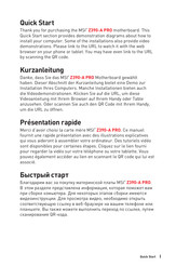
Quick Start
Thank you for purchasing the MSI
®
Z390-A PRO motherboard. This
Quick Start section provides demonstration diagrams about how to
install your computer. Some of the installations also provide video
demonstrations. Please link to the URL to watch it with the web
browser on your phone or tablet. You may have even link to the URL
by scanning the QR code.
Kurzanleitung
Danke, dass Sie das MSI
®
Z390-A PRO Motherboard gewählt
haben. Dieser Abschnitt der Kurzanleitung bietet eine Demo zur
Installation Ihres Computers. Manche Installationen bieten auch
die Videodemonstrationen. Klicken Sie auf die URL, um diese
Videoanleitung mit Ihrem Browser auf Ihrem Handy oder Table
anzusehen. Oder scannen Sie auch den QR Code mit Ihrem Handy,
um die URL zu öffnen.
Présentation rapide
Merci d’avoir choisi la carte mère MSI
®
Z390-A PRO. Ce manuel
fournit une rapide présentation avec des illustrations explicatives
qui vous aideront à assembler votre ordinateur. Des tutoriels vidéo
sont disponibles pour certaines étapes. Cliquez sur le lien fourni
pour regarder la vidéo sur votre téléphone ou votre tablette. Vous
pouvez également accéder au lien en scannant le QR code qui lui est
associé.
Быстрый старт
Благодарим вас за покупку материнской платы MSI
®
Z390-A PRO.
В этом разделе представлена информация, которая поможет вам
при сборке комьютера. Для некоторых этапов сборки имеются
видеоинструкции. Для просмотра видео, необходимо открыть
соответствующую ссылку в веб-браузере на вашем телефоне или
планшете. Вы также можете выполнить переход по ссылке, путем
сканирования QR-кода.
- Manuals
- Brands
- MSI Manuals
- Motherboard
- Z390-A PRO
Manuals and User Guides for MSI Z390-A PRO. We have 2 MSI Z390-A PRO manuals available for free PDF download: Manual, Quick Start Manual
MSI Z390-A PRO Manual (158 pages)
Brand: MSI
|
Category: Motherboard
|
Size: 9.58 MB
Table of Contents
-
English
11
-
Table of Contents
11
-
Safety Information
12
-
Specifications
13
-
Package Contents
18
-
Rear I/O Panel
19
-
Overview of Components
22
-
CPU Socket
23
-
DIMM Slots
24
-
PCI_E1~6: Pcie Expansion Slots
25
-
SATA1~6: SATA 6Gb/S Connectors
25
-
M2_1: M.2 Slot (Key M)
26
-
JTPM1: TPM Module Connector
26
-
JFP1, JFP2: Front Panel Connectors
27
-
JCOM1: Serial Port Connector
27
-
JTBT1: Thunderbolt Add-On Card Connector
27
-
CPU_PWR1, ATX_PWR1, PCIE_PWR1: Power Connectors
28
-
JUSB3~4: USB 3.1 Gen1 Connectors
29
-
JLPT1: Parallel Port Connector
30
-
JUSB1~2: USB 2.0 Connectors
30
-
CPU_FAN1, PUMP_FAN1, SYS_FAN1~5: Fan Connectors
31
-
JAUD1: Front Audio Connector
32
-
JCI1: Chassis Intrusion Connector
32
-
JBAT1: Clear CMOS (Reset BIOS) Jumper
33
-
JOC1: Front OC Button Connector
33
-
JRGB1: RGB LED Connector
34
-
EZ Debug LED
34
-
Installing Utilities
35
-
Installing Windows 10
35
-
Installing Drivers
35
-
Installing OS, Drivers & Utilities
35
-
BIOS Setup
36
-
Entering BIOS Setup
36
-
Resetting BIOS
37
-
Updating BIOS
37
-
EZ Mode
38
-
Advanced Mode
40
-
OC Menu
41
-
-
Deutsch
47
-
Sicherheitshinweis
48
-
Spezifikationen
49
-
Packungsinhalt
54
-
Rückseite E/A
55
-
Übersicht der Komponenten
58
-
CPU Sockel
59
-
DIMM-Steckplätze
60
-
PCI_E1~6: Pcie Erweiterungssteckplätze
61
-
SATA1~6: SATA 6Gb/S Anschlüsse
61
-
JTPM1: TPM Anschluss
62
-
M2_1: M.2 Steckplatz (Key M)
62
-
JCOM1: Serieller Anschluss
63
-
JFP1, JFP2: Frontpanel-Anschlüsse
63
-
JTBT1: Anschluss für Thunderbolt-Erweiterungskarte
63
-
CPU_PWR1, ATX_PWR1, PCIE_PWR1: Stromanschlüsse
64
-
JUSB3~4: USB 3.1 Gen1 Anschlüsse
65
-
JLPT1: Parallele Schnittstelle
66
-
JUSB1~2: USB 2.0 Anschlüsse
66
-
CPU_FAN1, PUMP_FAN1, SYS_FAN1~5: Stromanschlüsse für Lüfter
67
-
JAUD1: Audioanschluss des Frontpanels
68
-
JCI1: Gehäusekontaktanschluss
68
-
JBAT1: Clear CMOS Steckbrücke (Reset BIOS)
69
-
JOC1: Anscluss für Front OC Taste
69
-
EZ Debug LED
70
-
JRGB1: RGB LED Anschluss
70
-
Installation von OS, Treibern und Utilities
71
-
Installation von Treibern
71
-
Installation von Utilities
71
-
Installation von Windows ® 10
71
-
BIOS Setup
72
-
Öffnen des BIOS Setups
72
-
Aktualisierung des BIOS
73
-
Reset des BIOS
73
-
EZ Modus
74
-
Erweiterter Modus
76
-
OC Menü
77
-
-
Français
83
-
Informations de Sécurité
84
-
Spécifications
85
-
Contenu
90
-
Panneau Arrière Entrée / Sortie
91
-
Vue D’ensemble des Composants
94
-
Socket Processeur
95
-
Slots DIMM
96
-
PCI_E1~6 : Slots D’extension Pcie
97
-
SATA1~6 : Connecteurs SATA 6Gb/S
97
-
JTPM1 : Connecteur de Module TPM
98
-
M2_1 : Slots M.2 (Touche M)
98
-
JCOM1 : Connecteur de Port Série
99
-
JFP1, JFP2 : Connecteurs de Panneau Avant
99
-
JTBT1 : Connecteur de Carte Additionnelle Thunderbolt
99
-
CPU_PWR1, ATX_PWR1, PCIE_PWR1 : Connecteurs D’alimentation
100
-
JUSB3~4 : Connecteurs USB 3.1 Gen1
101
-
JLPT1 : Connecteur de Port Parallèle
102
-
JUSB1~2 : Connecteurs USB 2.0
102
-
CPU_FAN1, PUMP_FAN1, SYS_FAN1~5 : Connecteurs Pour Ventilateurs
103
-
JAUD1 : Connecteur Audio Avant
104
-
JCI1 : Connecteur Intrusion Châssis
104
-
JBAT1 : Cavalier Clear CMOS (Réinitialisation BIOS)
105
-
JOC1 : Connecteur de Bouton OC Avant
105
-
EZ Debug LED
106
-
JRGB1 : Connecteurs LED RGB
106
-
Installer Les Pilotes
107
-
Installer Les Utilitaires
107
-
Installer OS, Pilotes & Utilitaires
107
-
Installer Windows® 10
107
-
Configuration du BIOS
108
-
Entrer Dans L’interface Setup du BIOS
108
-
Mettre Le BIOS À Jour
109
-
Réinitialiser Le BIOS
109
-
EZ Mode
110
-
Advanced Mode (Mode Avancé)
112
-
OC Menu (Menu Overclocking)
113
-
-
Русский
119
-
Безопасное Использование Продукции
120
-
Технические Характеристики
121
-
Комплект Поставки
126
-
Задняя Панель Портов Ввода/ Вывода
127
-
Компоненты Материнской Платы
130
-
Процессорный Сокет
131
-
Слоты DIMM
132
-
PCI_E1~6: Слоты Расширения Pcie
133
-
SATA1~6: Разъемы SATA 6Гб/С
133
-
JTPM1: Разъем Модуля ТРМ
134
-
M2_1: Разъем M.2 (Ключ M)
134
-
JCOM1: Разъем Последовательного Порта
135
-
JFP1, JFP2: Разъемы Передней Панели
135
-
JTBT1: Разъем Для Установки Карты Расширения Thunderbolt
135
-
CPU_PWR1, ATX_PWR1, PCIE_PWR1: Разъемы Питания
136
-
JUSB3~4: Разъемы USB 3.1 Gen1
137
-
JLPT1: Разъем Параллельного Порта
138
-
JUSB1~2: Разъемы USB 2.0
138
-
CPU_FAN1, PUMP_FAN1, SYS_FAN1~5: Разъемы Вентиляторов
139
-
JAUD1: Разъем Аудио Передней Панели
140
-
JCI1: Разъем Датчика Открытия Корпуса
140
-
JBAT1: Джампер Очистки Данных CMOS (Сброс BIOS)
141
-
JOC1: Разъем OC На Передней Панели
141
-
JRGB1: Разъем RGB LED
142
-
Индикаторы Отладки EZ
142
-
Установка Windows® 10
143
-
Установка Драйверов
143
-
Установка ОС, Драйверов И Утилит
143
-
Установка Утилит
143
-
Вход В Настройки BIOS
144
-
Настройка BIOS
144
-
Обновление BIOS
145
-
Сброс BIOS
145
-
Режим EZ
146
-
Режим Разгона
148
-
Меню OC
149
-
Advertisement
MSI Z390-A PRO Quick Start Manual (78 pages)
Brand: MSI
|
Category: Motherboard
|
Size: 6.25 MB
Table of Contents
-
Quick Start
1
-
Preparing Tools and Components
1
-
Installing a Processor
2
-
Installing DDR4 Memory
3
-
Connecting the Front Panel Header
4
-
Installing the Motherboard
5
-
Installing SATA Drives
6
-
Installing a Graphics Card
7
-
Connecting Peripheral Devices
8
-
Connecting the Power Connectors
9
-
Power on
10
-
Table of Contents
11
-
-
Specifications
13
-
Package Contents
18
-
Block Diagram
19
-
Rear I/O Panel
20
-
LAN Port LED Status Table
20
-
Audio Ports Configuration
20
-
Realtek Audio Console
21
-
-
Overview of Components
23
-
CPU Socket
25
-
DIMM Slots
26
-
PCI_E1~6: Pcie Expansion Slots
27
-
SATA1~6: SATA 6Gb/S Connectors
27
-
M2_1: M.2 Slot (Key M)
28
-
JTPM1: TPM Module Connector
28
-
JFP1, JFP2: Front Panel Connectors
29
-
JCOM1: Serial Port Connector
29
-
JTBT1: Thunderbolt Add-On Card Connector
29
-
CPU_PWR1, ATX_PWR1, PCIE_PWR1: Power Connectors
30
-
JUSB3~4: USB 3.1 Gen1 Connectors
31
-
JUSB1~2: USB 2.0 Connectors
32
-
JLPT1: Parallel Port Connector
32
-
CPU_FAN1, PUMP_FAN1, SYS_FAN1~5: Fan Connectors
33
-
JAUD1: Front Audio Connector
34
-
JCI1: Chassis Intrusion Connector
34
-
JBAT1: Clear CMOS (Reset BIOS) Jumper
35
-
JOC1: Front OC Button Connector
35
-
JRGB1: RGB LED Connector
36
-
EZ Debug LED
36
-
-
Installing OS, Drivers & Utilities
37
-
Installing Windows 10
37
-
Installing Drivers
37
-
Installing Utilities
37
-
-
Mystic Light
38
-
Device LED Effect Control Screen
38
-
-
BIOS Setup
41
-
Entering BIOS Setup
41
-
Resetting BIOS
42
-
Updating BIOS
42
-
EZ Mode
43
-
Advanced Mode
45
-
Settings
46
-
Advanced
46
-
Boot
53
-
Security
54
-
Save & Exit
55
-
M-Flash
62
-
Oc Profile
63
-
Hardware Monitor
64
-
-
RAID Configuration
65
-
Enabling Intel ® Rapid Storage Technology
65
-
Creating RAID Volume
66
-
Removing a RAID Volume
67
-
Resetting Disks to Non-RAID
68
-
Rebuilding RAID Array
69
-
Installing RAID Driver
70
-
Installing Intel ® Rapid Storage Technology Software
70
-
-
Intel ® Optane™ Memory Configuration
71
-
System Requirements
71
-
Installing the Intel ® Optane™ Memory
71
-
Removing the Intel ® Optane™ Memory
73
-
-
Troubleshooting
74
-
Regulatory Notices
75
Advertisement
Related Products
-
MSI Z390-S01
-
MSI Z370 GAMING PRO CARBON
-
MSI Z370 GAMING PLUS
-
MSI Z370I GAMING PRO CARBON AC
-
MSI Z370M MORTAR
-
MSI Z370-A PRO
-
MSI Z370-A
-
MSI Z68MA-ED55 (B3)
-
MSI Z77IA-E53 series
-
MSI MEG Unify-X Z690
MSI Categories
Motherboard
![]()
Laptop
Video Card
![]()
Desktop
![]()
Monitor
More MSI Manuals
![]()
Quick Start
Thank you for purchasing the MSI® Z390-A PRO motherboard. This Quick Start section provides demonstration diagrams about how to install your computer. Some of the installations also provide video demonstrations. Please link to the URL to watch it with the web browser on your phone or tablet. You may have even link to the URL by scanning the QR code.
Preparing Tools and Components
Intel® LGA 1151 CPU
CPU Fan
Chassis
DDR4 Memory
|
Power Supply Unit |
Graphics Card |
Thermal Paste
|
SATA Hard Disk Drive |
SATA DVD Drive |
|
Phillips Screwdriver |
A Package of Screws |
Quick Start 1

Installing a Processor |
2 |
|
1 |
3
6 
8
2 Quick Start
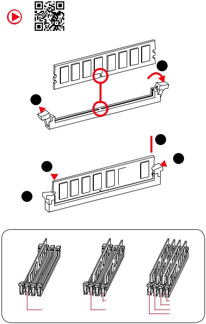
Installing DDR4 memory
1
1 
2
 3 2
3 2 


3 


|
DIMMB2 |
DIMMB2 |
|
|
DIMMB1 |
||
|
DIMMA2 |
DIMMA2 |
DIMMA2 |
|
DIMMA1 |
Quick Start 3
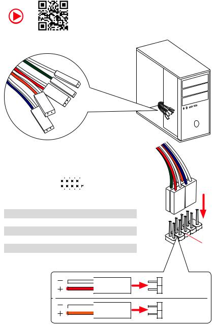
Connecting the Front Panel Header
|
— |
|||
|
LED |
|||
|
LED+ |
POWER |
||
|
POWER |
|||
|
LED |
|||
|
SW |
HDD |
||
|
POWER |
|||
|
SW |
|||
|
RESET |
|
Power LED |
Power Switch |
||||||||||||||||
|
+ — + — |
|||||||||||||||||
|
JFP1 |
2 |
10 |
|||||||||||||||
|
1 |
9 |
||||||||||||||||
|
+ — — + |
Reserved |
||||||||||||||||
|
HDD LED |
Reset Switch |
||||||||||||||||
|
1 |
HDD LED + |
2 |
Power LED + |
||||||||||||||
|
3 |
HDD LED — |
4 |
Power LED — |
||||||||||||||
|
5 |
Reset Switch |
6 |
Power Switch |
||||||||||||||
|
7 |
Reset Switch |
8 |
Power Switch |
||||||||||||||
|
9 |
Reserved |
10 |
No Pin |
||||||||||||||
HDD LED
 POWER LED
RESETSW
HDDLED
HDD LED — HDD LED +
POWER LED — POWER LED +
4 Quick Start
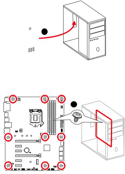
Installing the Motherboard
1
2
BAT1
Quick Start 5
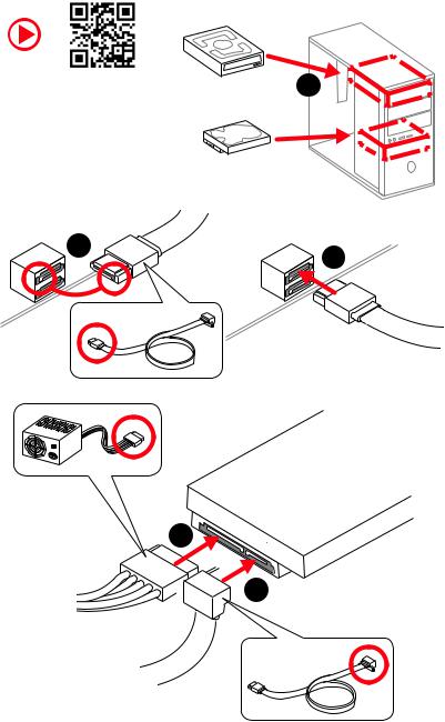
Installing SATA Drives
|
1 |
|
5
 4
4
6 Quick Start
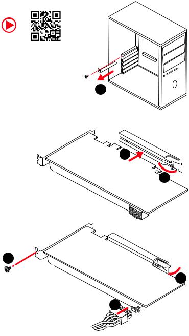
Installing a Graphics Card
1
3
2 
5
 4
4
6 

Quick Start 7
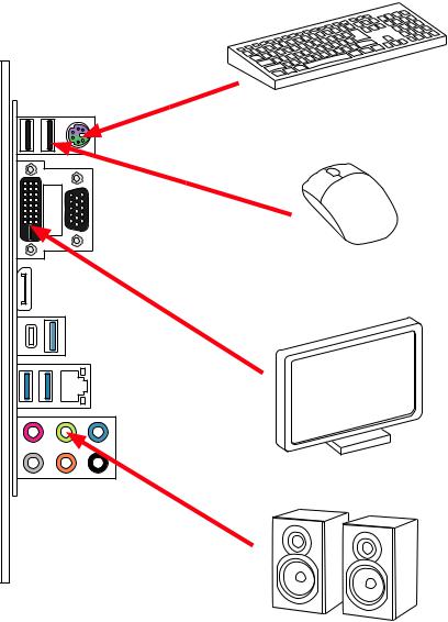
Connecting Peripheral Devices
8 Quick Start
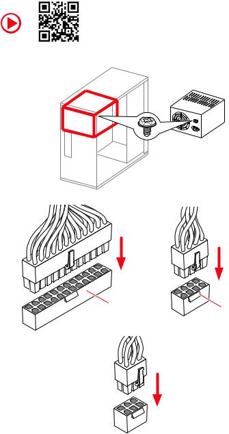
Connecting the Power Connectors
PCIE_PWR1
Quick Start 9
|
Contents |
|
|
Quick Start ………………………………………………………………………………………………. |
1 |
|
Preparing Tools and Components……………………………………………………………….. |
1 |
|
Installing a Processor………………………………………………………………………………… |
2 |
|
Installing DDR4 memory ……………………………………………………………………………. |
3 |
|
Connecting the Front Panel Header…………………………………………………………….. |
4 |
|
Installing the Motherboard…………………………………………………………………………. |
5 |
|
Installing SATA Drives………………………………………………………………………………… |
6 |
|
Installing a Graphics Card ………………………………………………………………………….. |
7 |
|
Connecting Peripheral Devices …………………………………………………………………… |
8 |
|
Connecting the Power Connectors………………………………………………………………. |
9 |
|
Power On………………………………………………………………………………………………… |
10 |
|
Specifications…………………………………………………………………………………………. |
13 |
|
Package contents …………………………………………………………………………………… |
18 |
|
Block Diagram ………………………………………………………………………………………. |
19 |
|
Rear I/O Panel ……………………………………………………………………………………….. |
20 |
|
LAN Port LED Status Table……………………………………………………………………….. |
20 |
|
Audio Ports Configuration ………………………………………………………………………… |
20 |
|
Realtek Audio Console …………………………………………………………………………….. |
21 |
|
Overview of Components ………………………………………………………………………… |
23 |
|
CPU Socket …………………………………………………………………………………………….. |
25 |
|
DIMM Slots……………………………………………………………………………………………… |
26 |
|
PCI_E1~6: PCIe Expansion Slots……………………………………………………………….. |
27 |
|
SATA1~6: SATA 6Gb/s Connectors …………………………………………………………….. |
27 |
|
M2_1: M.2 Slot (Key M) …………………………………………………………………………….. |
28 |
|
JTPM1: TPM Module Connector………………………………………………………………… |
28 |
|
JFP1, JFP2: Front Panel Connectors …………………………………………………………. |
29 |
|
JCOM1: Serial Port Connector ………………………………………………………………….. |
29 |
|
JTBT1: Thunderbolt Add-on Card Connector ……………………………………………… |
29 |
|
CPU_PWR1, ATX_PWR1, PCIE_PWR1: Power Connectors……………………………. |
30 |
|
JUSB3~4: USB 3.1 Gen1 Connectors …………………………………………………………. |
31 |
|
JUSB1~2: USB 2.0 Connectors………………………………………………………………….. |
32 |
|
JLPT1: Parallel Port Connector ………………………………………………………………… |
32 |
|
CPU_FAN1, PUMP_FAN1, SYS_FAN1~5: Fan Connectors…………………………….. |
33 |
|
JAUD1: Front Audio Connector …………………………………………………………………. |
34 |
|
JCI1: Chassis Intrusion Connector…………………………………………………………….. |
34 |
|
JBAT1: Clear CMOS (Reset BIOS) Jumper ………………………………………………….. |
35 |
|
JOC1: Front OC Button Connector …………………………………………………………….. |
35 |
Contents 11
|
JRGB1: RGB LED connector……………………………………………………………………… |
36 |
|
EZ Debug LED…………………………………………………………………………………………. |
36 |
|
Installing OS, Drivers & Utilities ………………………………………………………………. |
37 |
|
Installing Windows® 10…………………………………………………………………………….. |
37 |
|
Installing Drivers …………………………………………………………………………………….. |
37 |
|
Installing Utilities ……………………………………………………………………………………. |
37 |
|
MYSTIC LIGHT………………………………………………………………………………………… |
38 |
|
Device LED effect control screen ………………………………………………………………. |
38 |
|
BIOS Setup…………………………………………………………………………………………….. |
41 |
|
Entering BIOS Setup………………………………………………………………………………… |
41 |
|
Resetting BIOS………………………………………………………………………………………… |
42 |
|
Updating BIOS…………………………………………………………………………………………. |
42 |
|
EZ Mode …………………………………………………………………………………………………. |
43 |
|
Advanced Mode ………………………………………………………………………………………. |
45 |
|
SETTINGS……………………………………………………………………………………………….. |
46 |
|
Advanced………………………………………………………………………………………………… |
46 |
|
Boot……………………………………………………………………………………………………….. |
53 |
|
Security………………………………………………………………………………………………….. |
53 |
|
Save & Exit……………………………………………………………………………………………… |
54 |
|
OC………………………………………………………………………………………………………….. |
56 |
|
M-FLASH ……………………………………………………………………………………………….. |
62 |
|
OC PROFILE……………………………………………………………………………………………. |
63 |
|
HARDWARE MONITOR……………………………………………………………………………… |
64 |
|
RAID Configuration…………………………………………………………………………………. |
65 |
|
Enabling Intel® Rapid Storage Technology …………………………………………………. |
65 |
|
Creating RAID Volume …………………………………………………………………………….. |
66 |
|
Removing a RAID Volume ………………………………………………………………………… |
67 |
|
Resetting Disks to Non-RAID ……………………………………………………………………. |
68 |
|
Rebuilding RAID Array……………………………………………………………………………… |
69 |
|
Installing RAID Driver………………………………………………………………………………. |
70 |
|
Installing Intel® Rapid Storage Technology Software …………………………………… |
70 |
|
Intel® Optane™ Memory Configuration …………………………………………………….. |
71 |
|
System Requirements …………………………………………………………………………….. |
71 |
|
Installing the Intel® Optane™ memory ………………………………………………………. |
71 |
|
Removing the Intel® Optane™ memory ……………………………………………………… |
73 |
|
Troubleshooting …………………………………………………………………………………….. |
74 |
|
Regulatory Notices…………………………………………………………………………………. |
75 |
12 Contents

Specifications
|
Supports Intel® Core™ 9000 Series family/ 8th Gen Intel® |
||
|
CPU |
Core™ / Pentium® Gold / Celeron® processors for LGA 1151 |
|
|
socket |
||
|
* Please go to www.intel.com for more compatibility information. |
||
|
Chipset |
Intel® Z390 Chipset |
|
|
y4x DDR4 memory slots, support up to 64GB* |
||
|
ySupports DDR4 4400(OC)/ 4300(OC)/ 4266(OC)/ 4200(OC)/ |
||
|
4133(OC)/ 4000(OC)/ 3866(OC)/ 3733(OC)/ 3600(OC)/ |
||
|
3466(OC)/ 3400(OC)/ 3333(OC)/ 3300(OC)/ 3200(OC)/ 3000(OC) |
||
|
Memory |
/ 2800(OC)/ 2666/ 2400/ 2133 MHz* |
|
|
ySupports Dual-Channel mode |
||
|
ySupports non-ECC, un-buffered memory |
||
|
ySupports Intel® Extreme Memory Profile (XMP) |
||
|
* Please refer www.msi.com for more information on compatible memory. |
||
|
y2x PCIe 3.0 x16 slots |
||
|
Expansion Slot |
y4x PCIe 3.0 x1 slots |
|
|
y1 x M.2 slot with E key for Integrated Intel® Wireless-AC |
||
|
(CNVi) module only |
||
|
y1x VGA port, supports a maximum resolution of |
||
|
2048×1536@50Hz, 2048×1280@60Hz, 1920×1200@60Hz |
||
|
Onboard Graphics |
y1x DVI-D port, supports a maximum resolution of |
|
|
1920×1200@60Hz |
||
|
y1x DisplayPort, supports a maximum resolution of |
||
|
4096×2304@60Hz |
||
|
Multi-GPU |
ySupports 2-Way AMD® CrossFire™ Technology |
|
|
Intel® Z390 Chipset |
||
|
y6x SATA 6Gb/s ports* |
||
|
y1x M.2 slot (Key M) |
||
|
Storage |
Supports up to PCIe 3.0 x4 and SATA 6Gb/s, 2242/ 2260/ |
|
|
2280/ 22110 storage devices |
||
|
Intel® Optane™ Memory Ready** |
||
|
* The SATA2 will be unavailable when installing M.2 SATA device into M.2 slot. |
||
|
** Before using Intel® Optane™ memory modules, please ensure that you have |
||
|
updated the drivers and BIOS to the latest version from MSI website. |
||
|
Continued on next page |
Specifications 13

|
Continued from previous page |
||
|
Intel® Z390 Chipset |
||
|
RAID |
ySupports RAID 0, RAID1, RAID 5 and RAID 10 for SATA |
|
|
storage devices |
||
|
LAN |
y1x Intel® I219-V Gigabit LAN controller |
|
|
yIntel® Z390 Chipset |
||
|
2x USB 3.1 Gen2 (SuperSpeed USB 10Gbps) ports (1x |
||
|
Type-A port and 1x Type-C port) on the back panel |
||
|
6x USB 3.1 Gen1 (SuperSpeed USB) ports (2 Type-A |
||
|
USB |
ports on the back panel, 4 ports available through the |
|
|
internal USB 3.1 connectors) |
||
|
6x USB 2.0 (High-speed USB) ports (2 Type-A ports on |
||
|
the back panel, 4 ports available through the internal |
||
|
USB 2.0 connectors)* |
||
|
* The CNVI_1 and JUSB2 share the same bandwidth. Please refer to page 32 for |
||
|
details. |
||
|
Audio |
yRealtek® ALC892 Codec |
|
|
7.1-Channel High Definition Audio |
||
|
y1x PS/2 keyboard/ mouse combo port |
||
|
y2x USB 2.0 Type-A ports |
||
|
y1x VGA port |
||
|
y1x DVI-D port |
||
|
Back Panel |
y1x DisplayPort |
|
|
Connectors |
y1x USB 3.1 Gen2 Type-A port |
|
|
y1x USB 3.1 Gen2 Type-C port |
||
|
y1x LAN (RJ45) port |
||
|
y2x USB 3.1 Gen1 Type-A ports |
||
|
y6x audio jacks |
||
|
Continued on next page |
14 Specifications

Continued from previous page
y1x 24-pin ATX main power connector
y1x 8-pin ATX 12V power connector
y1x 6-pin ATX 12V power connector
y6x SATA 6Gb/s connectors
y2x M.2 slots (1 M-Key slot,1 E-Key slot)
y2x USB 3.1 Gen1 connectors (supports additional 4 USB 3.1 Gen1 ports)
y2x USB 2.0 connectors (supports additional 4 USB 2.0 ports)
y1x 4-pin CPU fan connector
y1x 4-pin Water Pump connector
Internal Connectors y5x 4-pin system fan connectors
y1x Front panel audio connector
y2x System panel connectors
y1x Chassis Intrusion connector
y1x 4-pin RGB LED connector
y1x Serial Port connector
y1x Clear CMOS jumper
y1x Parallel port connector
y1x TPM module connector
y1x thunderbolt Add-on card connector
y1x Front OC button connector
|
I/O Controller |
NUVOTON NCT6797 Controller Chip |
|
|
yCPU/System temperature detection |
||
|
Hardware Monitor |
yCPU/System fan speed detection |
|
|
yCPU/System fan speed control |
||
|
Form Factor |
yATX Form Factor |
|
|
y12 in. x 9.6 in. (30.5 cm x 24.4 cm) |
||
|
y1x 128 Mb flash |
||
|
BIOS Features |
yUEFI AMI BIOS |
|
|
yACPI 6.1, SMBIOS 2.8 |
||
|
yMulti-language |
||
|
Continued on next page |
Specifications 15
|
Continued from previous page |
||
|
yDrivers |
||
|
yDRAGON CENTER |
||
|
yMYSTIC LIGHT |
||
|
Software |
yCPU-Z MSI GAMING |
|
|
yIntel® Extreme Tuning Utility |
||
|
yGoogle Chrome™ |
,Google Toolbar, Google Drive |
|
|
yNorton™ Internet Security Solution |
||
|
yOC Performance |
||
|
Dragon Center |
yHardware Monitor |
|
|
yEyerest |
||
|
Features |
||
|
yLAN Manager |
||
|
Please refer to http://download.msi. |
||
|
yLive Update |
com/manual/mb/DRAGONCENTER2. |
|
|
pdf for more details. |
||
|
yAudio |
||
|
Audio Boost |
||
|
yNetwork |
||
|
Intel LAN with Network Manage |
||
|
Intel CNVi Ready |
||
|
yStorage |
||
|
Special Features |
Turbo M.2 |
|
|
yFan |
||
|
Pump Fan |
||
|
Smart Fan Control |
||
|
yLED |
||
|
Mystic Light Extension (RGB) |
||
|
EZ DEBUG LED |
||
|
Continued on next page |
16 Specifications
Continued from previous page
|
yProtection |
||
|
PCI-E Steel Armor |
||
|
PCI-E Steel Slot |
||
|
yPerformance |
||
|
Core Boost |
||
|
OC Genie |
||
|
Special Features |
Multi GPU-CrossFire Technology |
|
|
DDR4 Boost |
||
|
USB with type A+C |
||
|
Intel Turbo USB 3.1 Gen2 |
||
|
yVR |
||
|
VR Ready |
||
|
yBIOS |
||
|
Click BIOS 5 |
||
Specifications 17
Package contents
Please check the contents of your motherboard package. It should contain:
|
Motherboard |
Z390-A PRO |
||
|
Cable |
SATA 6Gb/s Cables |
2 |
|
|
M.2 Screw |
1 |
||
|
Accessories |
I/O Shield |
1 |
|
|
Case Badge |
1 |
||
|
VIP Card |
1 |
||
|
Application DVD |
Driver DVD |
1 |
|
|
Documentation |
Quick Installation Guide |
1 |
|
 Important
If any of the above items are damaged or missing, please contact your retailer.
18 Package contents
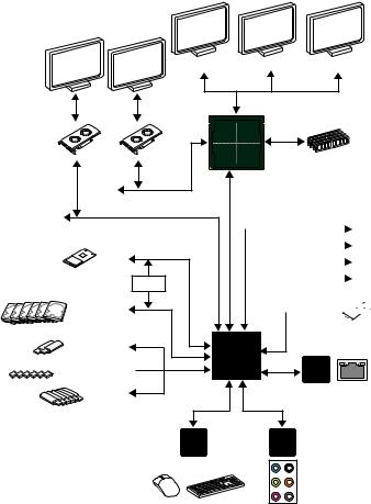
Block Diagram
DisplayPort
PCI Express Bus
x4
PCI Express Bus
|
1 x M.2 |
|
|
Switch |
PCI |
|
6 x SATA 6Gb/s |
BusExpress |
|
2 x USB 3.1 Gen2 |

 6 x USB 3.1 Gen1
6 x USB 2.0
LPC Bus
2 Channel DDR4 Memory
CPU
DMI 3.0
|
x1 |
PCIe x1 slot |
|
|
x1 |
||
|
PCIe x1 slot |
||
|
x1 |
||
|
PCIe x1 slot |
||
|
x1 |
||
|
PCIe x1 slot |
||
 1x M.2
(E Key for Intel CNVi module only)
chipset
Intel
I219-V
|
NV6797 |
Realtek |
|
Super I/O |
ALC892 |
|
P/S2 Mouse / Keyboard |
Audio Jacks |
Block Diagram 19
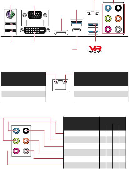
Rear I/O Panel
|
PS/2 |
LAN |
Audio Ports |
|
|
VGA |
USB 3.1 Gen2 |
||
|
Type-A |
|||
|
DisplayPort |
|||
|
USB 2.0 |
DVI-D |
USB 3.1 Gen1 Type-A |
|
|
USB 3.1 Gen2 Type-C |
LAN Port LED Status Table
Link/ Activity LED
|
Status |
Description |
|
Off |
No link |
|
Yellow |
Linked |
|
Blinking |
Data activity |
Speed LED
|
Status |
Description |
|
Off |
10 Mbps connection |
|
Green |
100 Mbps connection |
|
Orange |
1 Gbps connection |
Audio Ports Configuration
|
Audio Ports |
Channel |
||
|
2 |
4 |
6 |
8 |
|
Line-In |
|||
|
Line-Out/ Front Speaker Out ● |
● |
● |
● |
|
Rear Speaker Out |
● |
● |
● |
|
Center/ Subwoofer Out |
● |
● |
|
|
Side Speaker Out |
● |
Mic In
(●: connected, Blank: empty)
20 Rear I/O Panel
![]()
Realtek Audio Console
After Realtek Audio Console is installed. You can use it to change sound settings to get better sound experience.
|
Application Enhancement |
Advanced Settings |
Device 
Selection
 Main Volume
|
Connector Settings |
||||
|
Jack Status |
yDevice Selection — allows you to select a audio output source to change the related options. The check sign indicates the devices as default.
yApplication Enhancement — the array of options will provide you a complete guidance of anticipated sound effect for both output and input device.
yMain Volume — controls the volume or balance the right/left side of the speakers that you plugged in front or rear panel by adjust the bar.
yAdvanced Settings — provides the mechanism to deal with 2 independent audio streams.
yJack Status — depicts all render and capture devices currently connected with your computer.
yConnector Settings — configures the connection settings.
Auto popup dialog
When you plug into a device at an audio jack, a dialogue window will pop up asking you which device is current connected.
Each jack corresponds to its default setting as shown on the next page.
Important
The pictures above for reference only and may vary from the product you purchased.
Rear I/O Panel 21
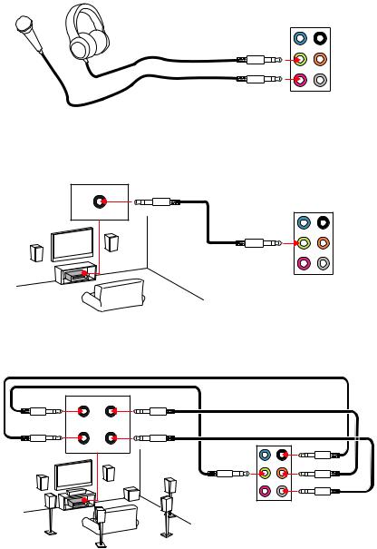
Audio jacks to headphone and microphone diagram
Audio jacks to stereo speakers diagram
AUDIO INPUT
Audio jacks to 7.1-channel speakers diagram
AUDIO INPUT
Front Center/
Subwoofer
22 Rear I/O Panel
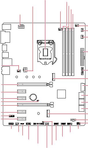
Overview of Components
SYS_FAN1
PCI_E1
PCI_E2
PCI_E3
JBAT1
PCI_E4
PCI_E5
JTPM1
PCI_E6
|
CPU Socket |
|||
|
DIMMA1 |
|||
|
PCIE_PWR1 |
DIMMA2 |
||
|
CPU_FAN1 |
DIMMB1 |
||
|
CPU_PWR1 |
DIMMB2 |
||
|
PUMP_FAN1 |
|||
|
SYS_FAN5 |
|||
|
SYS_FAN4 |
|||
|
ATX_PWR1 |
|||
|
JUSB4 |
|||
|
M2_1 |
|||
|
JUSB3 |
|||
|
BAT1 |
SATA▼1▲2 |
||
|
SATA▼3▲4 |
|||
|
SATA▼5▲6 |
|||
|
CNVI_1 |
|||
|
JTBT1 |
|||
|
JOC1 |
|||
|
JAUD1 |
JFP2 |
||
|
SYS_FAN2 |
JFP1 |
||
|
JRGB1 |
JUSB2 |
||
|
JCOM1 |
|||
|
JUSB1 |
|||
|
JLPT1 |
JCI1 |
||
|
SYS_FAN3 |
Overview of Components 23

Component Contents
|
Port Name |
Port Type |
Page |
|
|
CPU_FAN1, PUMP_FAN1, SYS_FAN1~5 |
Fan Connectors |
33 |
|
|
CPU_PWR1, ATX_PWR1, PCIE_PWR1 |
Power Connectors |
30 |
|
|
CPU Socket |
LGA 1151 Socket |
25 |
|
|
DIMMA1/A2/B1/B2 |
DIMM Slots |
26 |
|
|
JAUD1 |
Front Audio Connector |
34 |
|
|
JBAT1 |
Clear CMOS Jumper |
35 |
|
|
JCI1 |
Chassis Intrusion Connector |
34 |
|
|
JCOM1 |
Serial Port Connector |
29 |
|
|
JFP1, JFP2 |
Front Panel Connectors |
29 |
|
|
JLPT1 |
Parallel Port Connector |
32 |
|
|
JOC1 |
Front OC Button Connector |
35 |
|
|
JRGB1 |
RGB LED connector |
36 |
|
|
JTBT1 |
Thunderbolt Add-on Card |
29 |
|
|
Connector |
|||
|
JTPM1 |
TPM Module Connector |
28 |
|
|
JUSB1~2 |
USB 2.0 Connectors |
32 |
|
|
JUSB3~4 |
USB 3.1 Gen1 Connectors |
31 |
|
|
M2_1 |
M.2 Slot (Key M) |
28 |
|
|
PCI_E1~6 |
PCIe Expansion Slots |
27 |
|
|
SATA1~6 |
SATA 6Gb/s Connectors |
27 |
|
24 Overview of Components
Главная » MSI » Руководство пользователя материнской платы MSI Z390 A PRO
Содержание скрывать
1
Руководство пользователя материнской платы MSI Z390 A PRO
2
Похожие сообщения
Руководство пользователя материнской платы MSI Z390 A PRO
View Fullscreen
Похожие сообщения
-

Материнская плата MSi B550M PRO / A520M PRO Руководство пользователя
Материнская плата MSi B550M PRO / A520M PRO Руководство пользователя — оптимизированный PDF Материнская плата MSi B550M PRO / A520M PRO Руководство пользователя -…
-
Материнская плата ASUS H170-PRO Руководство пользователя
Руководство пользователя материнской платы ASUS H170-PRO — Скачать
-
Руководство пользователя материнской платы msi H510M PRO
Материнская плата msi H510M PRO ИНСТРУКЦИЯ ПО БЕЗОПАСНОСТИ Перед установкой или…
-
Руководство пользователя ноутбука MSi
Руководство пользователя ноутбука MSi — Оптимизированный PDF-файл Руководство пользователя ноутбука MSi — Исходный файл PDF


Оставить комментарий
Ваш электронный адрес не будет опубликован. Обязательные поля помечены * *
КОММЕНТАРИЙ *
Имя и фамилия
Эл. адрес
Cайт
Сохраните мое имя, адрес электронной почты и веб-сайт в этом браузере для следующего комментария.