-
Драйверы
18
-
Инструкции по эксплуатации
3
Языки:

MSI Z77A-G43 инструкция по эксплуатации
(162 страницы)
- Языки:Русский
-
Тип:
PDF -
Размер:
18.93 MB -
Описание:
Материнская плата Intel
Просмотр

MSI Z77A-G43 инструкция по эксплуатации
(82 страницы)
- Языки:Английский
-
Тип:
PDF -
Размер:
8.12 MB
Просмотр

MSI Z77A-G43 инструкция по эксплуатации
(201 страница)
-
Тип:
PDF -
Размер:
22.59 MB
Просмотр
На NoDevice можно скачать инструкцию по эксплуатации для MSI Z77A-G43. Руководство пользователя необходимо для ознакомления с правилами установки и эксплуатации MSI Z77A-G43. Инструкции по использованию помогут правильно настроить MSI Z77A-G43, исправить ошибки и выявить неполадки.
Hide thumbs
Also See for Z77A-G43 GAMING:
- Manual (82 pages)
- Manual (164 pages)
,
-
Contents
-
Table of Contents
-
Bookmarks
Quick Links
Z77A-G43 GAMING
B75A-G43 GAMING
MS-7758 (v5.x) Manboard
G52-77581XT
Related Manuals for MSI Z77A-G43 GAMING
Summary of Contents for MSI Z77A-G43 GAMING
-
Page 1
Z77A-G43 GAMING B75A-G43 GAMING MS-7758 (v5.x) Manboard G52-77581XT… -
Page 2: Trademarks
Preface Preface Copyrght Notce The materal n ths document s the ntellectual property of MICRO-STAR INTERNA- TIONAL. We take every care n the preparaton of ths document, but no guarantee s gven as to the correctness of ts contents. Our products are under contnual mprove- ment and we reserve the rght to make changes wthout notce.
-
Page 3: TechnCal Support
If a problem arses wth your system and no soluton can be obtaned from the user’s manual, please contact your place of purchase or local dstrbutor. Alternatvely, please try the followng help resources for further gudance. Vst the MSI webste for techncal gude, BIOS updates, drver updates, and other nformaton: http://www.ms.com/servce/download/ Contact our techncal staff at: http://support.ms.com…
-
Page 4: Fcc-B RadO Frequency Interference Statement
Preface Preface FCC-B Rado Frequency Interference Statement Ths equpment has been tested and found to comply wth the lmts for a Class B dgtal devce, pursuant to Part 15 of the FCC Rules. These lmts are desgned to provde reasonable protecton aganst harmful nterference n a resdental nstallaton. Ths equpment generates, uses and can radate rado frequency energy and, f not nstalled and used n accordance wth the nstructons, may cause harmful nterference to rado communcatons.
-
Page 5: RadAtOn Exposure Statement
MS-7758 MS-7758 Radaton Exposure Statement Ths equpment comples wth FCC radaton exposure lmts set forth for an uncon- trolled envronment. Ths equpment and ts antenna should be nstalled and operated wth mnmum dstance 20 cm between the radator and your body. Ths equpment and ts antenna must not be co-located or operatng n conjuncton wth any other antenna or transmtter.
-
Page 6: Battery InformatOn
Replace only wth the same or equvalent type recommended by the manufacturer. Chemcal Substances Informaton In complance wth chemcal substances regulatons, such as the EU REACH Regulaton (Regulaton EC No. 1907/2006 of the European Parlament and the Councl), MSI provdes the nformaton of chemcal substances n products at: http://www.ms.com/html/popup/csr/evmtprtt_pcm.html…
-
Page 7: Weee (Waste ElectrCal And ElectronC EquPment) Statement
MSI wll comply wth the product take back requrements at the end of lfe of MSI-branded products that are sold nto the EU.
-
Page 8
MSI će poštovat zahtev o preuzmanju ovakvh prozvoda kojma je stekao vek trajanja, koj maju MSI oznaku koj su prodat u EU. Ove proz- vode možete vratt na lokalnm mestma za prkupljanje. -
Page 9
produttor d dett materal saranno obblgat a rtrare ogn prodotto alla fine del suo cclo d vta. MSI s adeguerà a tale Drettva rtrando tutt prodott marchat MSI che sono stat vendut all’nterno dell’Unone Europea alla fine del loro… -
Page 10: Table Of Contents
Preface Preface CONTENTS ▍ Copyrght Notce ……………….. Trademarks ……………….. Revson Hstory………………… Techncal Support……………… Safety Instructons ……………… FCC-B Rado Frequency Interference Statement………. v CE Conformty ………………..v Radaton Exposure Statement …………… v European Communty Complance Statement ……….v Tawan Wreless Statements …………….
-
Page 11
MS-7758 MS-7758 Chapter 2 BIOS Setup ……………..2-1 Enterng …………………… 2-2 Overvew ………………….2-2 Boot devce prorty bar ………………2-3 Operaton ………………….2-4 SETTINGS ………………….2-5 OC ……………………2-13 ECO ……………………2-18 BROWSER ………………….2-19 Installng Wnk ………………..2-19 UTILITIES ………………….2-20 Updatng the BIOS wth Lve Update ………….. -
Page 13: Chapter 1 GettNg Started
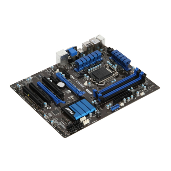
Chapter 1 Gettng Started Thank you for choosng the Z77A-G43 GAMING/ B75A-G43 GAMING Seres (MS-7758 v5.X) ATX motherboard. The Seres manboards are based on Intel Z77/ B75 chpset for optmal system efficency. ® Desgned to fit the advanced Intel LGA1155 ®…
-
Page 14: PackNg Contents
* These pctures are for reference only and may vary wthout notce. * The packng contents may vary accordng to the model you purchased. * If you need to purchase the optonal accessores or request part numbers, please vst the MSI webste at http://www.ms.com/ndex.php or consult the dealer.
-
Page 15: Assembly PrecautOns
MS-7758 Assembly Precautons ■ The components ncluded n ths package are prone to damage from electrostatc dscharge (ESD). Please adhere to the followng nstructons to ensure successful computer assembly. ■ Always turn off the power supply and unplug the power cord from the power outlet before nstallng or removng any computer component.
-
Page 16: MaNboard SpecFicatOns
Generaton Intel Core™ 7/ Core™ 5/ Core™ 3/ Pentum / Celeron ® ® ® Processors for LGA 1155 socket Chpset ■ Intel Z77 chpset (Z77A-G43 GAMING) ® ■ Intel B75 chpset (B75A-G43 GAMING) ® Supports Intel SBA by Intel ® ®…
-
Page 17
MS-7758 Connectors ■ Back panel 1x PS/2 keyboard/ mouse combo port 6x USB 2.0 ports (Z77A-G43 GAMING) or 4x USB 2.0 ports (B75A-G43 GAMING) 2x USB 3.0 ports 1x LAN port 1x HDMI port**, supportng a maxmum resoluton of 1920×1200… -
Page 18: Connectors QuCk GuDe
Gettng Started Connectors Quck Gude DIMM3 JPWR2 DIMM2 DIMM4 DIMM1 SYSFAN3 CPUFAN SYSFAN1 Back Panel JTURBO1 JPWR1 SYSFAN2 JUSB3 PCI_E1 SYSFAN4 PCI_E2 JBAT1 BATT PCI_E3 JCI1 SATA2 PCI1 SATA1 PCI_E4 SATA4 SATA3 PCI2 SATA6 SATA5 PCI3 JAUD1 JFP2 JFP1 JTPM1 JUSB1/ 2 JLPT1 JDLED3…
-
Page 19
MS-7758 Connectors Reference Gude Port Name Port Type Page Back Panel I/O Ports LGA 1155 CPU Socket 1-10 CPUFAN,SYSFAN1~4 Fan Power Connectors 1-23 DIMM1~4 DDR3 Memory Slots 1-16 JAUD1 Front Panel Audo Connector 1-27 JBAT1 Clear CMOS Jumper 1-30 JCI1 Chasss Intruson Connector 1-26 JCOM1… -
Page 20: Back Panel QuCk GuDe
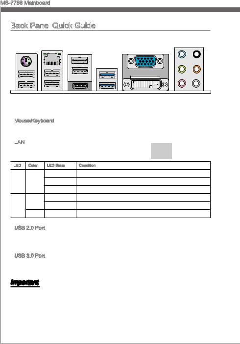
Gettng Started Back Panel Quck Gude (For Z77A-G43 GAMING) USB 2.0 Port Mouse/ Keyboard VGA Port RS-Out Lne-In USB 2.0 Port CS-Out Lne-Out SS-Out USB 2.0 Port HDMI Port USB 3.0 Port DVI-D Port ▶ Mouse/Keyboard A combnaton PS/2 mouse/keyboard DIN connector for a PS/2 mouse/keyboard.
-
Page 21
MS-7758 ▶ HDMI Port The Hgh-Definton Multmeda Interface (HDMI) s an all-dgtal audo-vdeo nterface that s capable of transmttng uncompressed streams. HDMI supports all types of TV formats, ncludng standard, enhanced, or hgh-definton vdeo, plus mult-channel dgtal audo on a sngle cable. ▶… -
Page 22: Cpu (Central ProcessNg UnT)
Ths manboard s desgned to support overclockng. Before attemptng to overclock, please make sure that all other system components can tolerate overclockng. Any attempt to operate beyond product specficatons s not recommend. MSI does not guarantee the damages or rsks caused by nadequate operaton beyond product specficatons.
-
Page 23
MS-7758 CPU & Cooler Installaton When nstallng a CPU, always remember to nstall a CPU cooler. A CPU cooler s necessary to prevent overheatng and mantan system stablty. Follow the steps below to ensure correct CPU and CPU cooler nstallaton. Wrong nstallaton can damage both the CPU and the manboard. -
Page 24
Gettng Started Inspect the CPU to check f t s Evenly spread a thn layer of properly seated n the socket. Press thermal paste (or thermal tape) on the loadng lever down and lock t the top of the CPU. Ths wll help n under the retenton tab. -
Page 25
MS-7758 Push down on the heatsnk untl the Inspect the manboard to ensure that four clps get wedged nto the holes the clp-ends have been properly on the manboard. Press the four locked n place. hooks down to fasten the cooler. As each hook locks nto poston a clck should be heard. -
Page 26: MountNg Screw Holes
Gettng Started Mountng Screw Holes When nstallng the manboard, first nstall the necessary mountng stands requred for a manboard on the mountng plate n your computer case. If there s an I/O back plate that came wth the computer case, please replace t wth the I/O backplate that came wth the manboard package.
-
Page 27: Power Supply
MS-7758 Power Supply JPWR1: ATX 24-pn Power Connector Ths connector allows you to connect an ATX 24-pn power supply. To connect the ATX 24-pn power supply, algn the power supply cable wth the connector and firmly press the cable nto the connector. If done correctly, the clp on the power cable should be hooked on the manboard’s power connector.
-
Page 28: Memory
Gettng Started Memory These DIMM slots are used for nstallng memory modules. For more nformaton on compatble components, please vst http://www.ms.com/servce/test-report DDR3 240-pn, 1.5V 48×2=96 pn 72×2=144 pn Dual-Channel mode Populaton Rule In Dual-Channel mode, the memory modules can transmt and receve data wth two data bus channels smultaneously.
-
Page 29
MS-7758 Installng Memory Modules Unlock the DIMM slot by pushng the mountng clps to the sde. Vertcally nsert the memory module nto the DIMM slot. The memory module has an off-center notch on the bottom that wll only allow t to fit one way nto the DIMM slot. Push the memory module deep nto the DIMM slot. -
Page 30: ExpansOn Slots
Gettng Started Expanson Slots Ths manboard contans numerous ports for expanson cards, such as dscrete graphcs or audo cards. PCIe Expanson Slot The PCIe slot supports the PCIe nterface expanson card. PCIe 3.0 x16 Slot PCIe 2.0 x16 Slot PCIe 2.0 x1 Slot PCI Expanson Slot The PCI slot supports addtonal LAN, SCSI, USB, and other add-on cards that comply wth PCI specficatons.
-
Page 31: Deo/ GraphCs Cards
nstalled by way of the manboard’s expanson slots. Addng on one or more dscrete vdeo cards wll sgnficantly boost the system’s graphcs performance. For best compatblty, MSI graphcs cards are recommended. Sngle Vdeo Card Installaton Determne what type of expanson slot(s) the vdeo card wll use.
-
Page 32
Important • Please ensure that all graphcs cards used n CrossFre™ mode are of the same brand and specficatons. For best compatblty wth the manboard, MSI graphcs cards are recommended. • Make sure to connect an adequate power supply to the power connectors on the graphcs cards to ensure stable operaton. -
Page 33
MS-7758 Boot up the computer and nstall the drvers and software ncluded n your vdeo card package. For more nformaton, please refer to the manual that came wth your vdeo card. After all of the hardware and software has been properly nstalled, reboot the sys- tem. -
Page 34: Internal Connectors
SATA4 SATA6 SATA1 SATA3 SATA5 SATA1~2 (6Gb/s), SATA3~6 (3Gb/s) (Z77A-G43 GAMING) SATA1 (6Gb/s), SATA2~6 (3Gb/s) (B75A-G43 GAMING) Important • Many SATA devces also need a power cable from the power supply. Such devces nclude dsk drves (HDD), sold state drves (SSD), and optcal drves (CD / DVD / Blu-Ray).
-
Page 35
MS-7758 CPUFAN,SYSFAN1~4: Fan Power Connectors The fan power connectors support system coolng fans wth +12V. If the motherboard has a System Hardware Montor chpset on-board, you must use a specally desgned fan wth a speed sensor to take advantage of the CPU fan control. Remember to connect all system fans. -
Page 36
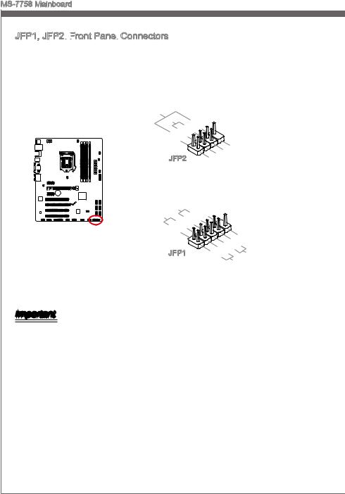
Gettng Started JFP1, JFP2: Front Panel Connectors These connectors connect to the front panel swtches and LEDs. The JFP1 connector s complant wth the Intel Front Panel I/O Connectvty Desgn Gude. When nstallng ® the front panel connectors, please use the optonal mConnectors to smplfy nstallaton. Plug all the wres from the computer case nto the mConnectors and then plug the mConnectors nto the motherboard. -
Page 37
MS-7758 JUSB3: USB 3.0 Expanson Connector The USB 3.0 port s backwards compatble wth USB 2.0 devces. It supports data transfer rates up to 5Gbts/s (SuperSpeed). BATT * The MB layout n ths figure s for reference only. USB 3.0 Bracket (optonal) Important •… -
Page 38
Gettng Started JUSB1~2: USB 2.0 Expanson Connector Ths connector s desgned for connectng hgh-speed USB perpherals such as USB HDDs, dgtal cameras, MP3 players, prnters, modems, and many others. BATT * The MB layout n ths figure s for reference only. USB 2.0 Bracket (optonal) Important Note that the VCC and GND pns must be connected correctly to avod possble dam-… -
Page 39
MS-7758 JAUD1: Front Panel Audo Connector Ths connector allows you to connect the front audo panel located on your computer case. Ths connector s complant wth the Intel Front Panel I/O Connectvty Desgn ® Gude. BATT JTPM1: TPM Module Connector Ths connector connects to a TPM (Trusted Platform Module). -
Page 40
Gettng Started JCOM1: Seral Port Connector Ths connector s a 16550A hgh speed communcaton port that sends/receves 16 bytes FIFOs. You can attach a seral devce. BATT JLPT1: Parallel Port Connector Ths connector s used to connect an optonal parallel port bracket. The parallel port s a standard prnter port that supports Enhanced Parallel Port (EPP) and Extended Capabltes Parallel Port (ECP) mode. -
Page 41
MS-7758 JDLED3: Voce Gene Connector (optonal) Ths connector s used to lnk to the voce control module (optonal). Please refer to ts user gude for more detals and usages. BATT JTURBO1: MultConnect Panel Connector (optonal) Ths connector s used to connect an optonal front panel for controlng the OC Gene and some addtonal functons. -
Page 42: Jumper
Gettng Started Jumper JBAT1: Clear CMOS Jumper There s CMOS RAM onboard that s external powered from a battery located on the motherboard to save system configuraton data. Wth the CMOS RAM, the system can automatcally boot nto the operatng system (OS) every tme t s turned on. If you want to clear the system configuraton, set the jumpers to clear the CMOS RAM.
-
Page 43: DrVers And UtLTEs
After you nstall the operatng system you wll need to nstall drvers to maxmze the performance of the new computer you just bult. MSI manbaord comes wth a Drver Dsc. Drvers allow the computer to utlze your manboard more efficently and take advantage of any specal features we provde.
-
Page 45: Chapter 2 Bios Setup
Chapter 2 BIOS Setup CLICK BIOS II s a revolutonary UEFI nterface that allows you to setup and configure your system for optmum use. Usng your mouse and keyboard, users can change BIOS settngs, montor CPU temperature, select the boot devce prorty and vew system nformaton such as the CPU name, DRAM capacty, the OS verson and the BIOS verson.
-
Page 46: EnterNg
BIOS Setup Enterng Power on the computer and the system wll start the Power On Self Test (POST) pro- cess. When the message below appears on the screen, please <DEL> key to enter CLICK BIOS II: Press DEL key to enter Setup Menu, F11 to enter Boot Menu If the message dsappears before you respond and you stll need to enter CLICK BIOS II, restart the system by turnng the computer OFF then back ON or pressng the RESET button.
-
Page 47: Boot DevCe PrOrTy Bar
■ ECO — Ths menu s related to energy-savng settngs. ■ BROWSER — Ths feature s used to enter the MSI Wnk web browser. ■ UTILITIES — Ths menu contans utltes for backup and update. ■ SECURITY — The securty menu s used to keep unauthorzed people from mak- ng any changes to the settngs.
-
Page 48: OperatOn
BIOS Setup Operaton CLICK BIOS II allows you to control BIOS settngs wth the mouse and the keyboard. The followng table lsts and descrbes the hot keys and the mouse operatons. Hot key Mouse Descrpton <↑↓→← > Select Item Move the cursor <Enter>…
-
Page 49: Settings
MS-7758 SETTINGS System Status ▶ System Date Ths allows you to set the system date that you want (usually the current date). The format s <day> <month> <date> <year>. Day of the week, from Sun to Sat, determned by BIOS. Read-only.
-
Page 50
BIOS Setup Advanced ▶ PCI Subsystem Settngs Press <Enter> to enter the sub-menu. ▶ PCIE GEN3 Ths tem s used to enable/ dsable the PCIe generaton 3 support. ▶ PCI Latency Tmer Controls how long each PCI devce can hold the bus before another takes over. When set to hgher values, every PCI devce can conduct transactons for a longer tme and thus mprove the effectve PCI bandwdth. -
Page 51
[Dsabled] Dsable the Ipv6 PXE boot support. ▶ SATA Mode (Only Z77A-G43 GAMING supports RAID mode) Ths tem s used to specfy RAID/ IDE/ AHCI mode for SATA port. Important You cannot swtch between AHCI and IDE f you already have your operatng system nstalled. -
Page 52
BIOS Setup ▶ Intel(R) Rapd Start Technology Press <Enter> to enter the sub-menu. ▶ Intel(R) Rapd Start Technology Ths tem s used to enable/ dsable the Intel Rapd Start technology. ▶ USB Configuraton Press <Enter> to enter the sub-menu. ▶ USB Controller Ths tem allows you to enable/ dsable the ntegrated USB 2.0 controller. -
Page 53
Allow you to enter BIOS setup wth hot key functon. Important If you want to enter BIOS n MSI Fast Boot mode, you have to clck the «GO2BIOS» tab on Fast Boot utlty screen or press the «GO2BIOS» button (optonal) on the motherboard. -
Page 54
Fast Boot s one of nnovaton n Wndows 8. When enabled, t allows user to dsable the ntalzatons of USB, PS2 and SATA devces for acceleratng the system bootng tme. Ths tem wll only be avalable when «MSI Fast Boot» s dsabled. [Enabled] Enable the Fast Boot configuraton. -
Page 55
MS-7758 ▶ Resume By RTC Alarm The field s used to enable or dsable the feature of bootng up the system on a scheduled tme/date. ▶ Date/ HH:MM:SS If Resume By RTC Alarm s set to [Enabled], the system wll automatcally resume (boot up) on a specfic date/hour/mnute/second specfied n these fields (usng the <+>… -
Page 56
BIOS Setup Save & Ext ▶ Dscard Changes and Ext Ths t s used to abandon all changes and ext setup. ▶ Save Changes and Reboot Ths tem s used to save changes and reboot the system. ▶ Save Changes Ths tem s used to save changes. -
Page 57
It shows the adjusted CPU frequency. Read-only. ▶ Adjust CPU Rato n OS Enable ths tem to allow CPU rato changes n the OS by usng MSI Control Center II. ▶ Internal PLL Overvoltage Ths tem s used to adjust the PLL voltage. -
Page 58
BIOS Setup ▶ EIST Enhanced Intel SpeedStep technology allows you to set the performance level of the mcroprocessor whether the computer s runnng on battery or AC power. Ths field only appears wth nstalled CPUs that support ths technology. ▶ Intel Turbo Boost Enables or dsables Intel Turbo Boost whch automatcally boosts CPU performance above rated specficatons (when applcatons requests the hghest performance state… -
Page 59
MS-7758 ▶ GT Rato Ths settng controls the rato of ntegrated graphcs frequency to enable the ntegrated graphcs to run at dfferent frequency combnatons. ▶ Adjusted GT Frequency It shows the adjusted ntegrated graphcs frequency. Read-only. ▶ Spread Spectrum Ths functon reduces the EMI (Electromagnetc Interference) generated by modulatng clock generator pulses. -
Page 60
BIOS Setup ▶ CPU Specficatons Press <Enter> to enter the sub-menu. Ths sub-menu hghlghts all the key features of your CPU. The nformaton wll vary by model and s read-only. You can also access ths nformaton at any tme by pressng [F4]. Press <Enter> to enter the sub-menu. ▶… -
Page 61
MS-7758 and nstructons from memory nto L2 cache for reducng the latency tme assocated wth memory reads. [Dsabled] Dsable the CPU hardware prefetcher. ▶ Adjacent Cache Lne Prefetch [Enabled] Enable or dsable the CPU hardware prefetcher to pre-fetch the adjacent cache lne. -
Page 62: Eco
BIOS Setup Important Once you clck the “ECO” button n the pre-set area, some tems n ECO menu wll be fixed and un-adjustable. ▶ EuP 2013 Energy Usng Products Lot 6 2013 (EUP) reduces power consumpton when system s off or n standby mode. Note: When enabled, the system wll not support RTC wake up event functons.
-
Page 63: Browser
MS-7758 BROWSER Please nstall the MSI «Wnk» applcaton first n the Wndows operatng system wth the MSI Drver Dsc before usng the browser. Then you can clck the BROWSER to access the Internet, e-mal and nstant messagng. Installng Wnk To nstall Wnk, follow the steps below: Power on your computer and enter Wndows operatng system.
-
Page 64: Utilities
Ths tool can detect and update your BIOS onlne so that you won’t need to spend tme searchng manually. Important HDD Backup and Lve Update request Wnk, please nstall the «Wnk» software appl- caton from MSI Drver Dsc n Wndows first. And then you can access these two utltes by clckng ther respectve buttons. 2-20…
-
Page 65
MS-7758 ▶ M-Flash ▶ BIOS Boot Functon Ths allows you to enable/ dsable the system to boot from the BIOS file nsde USB drve (FAT 32 format only). ▶ Select one file to boot When the BIOS Boot functon as sets to [Enabled], ths tem s selectable. Ths tem allows to select partcular BIOS file from the USB/ Storage (FAT 32 format only) drve. -
Page 66: UpdatNg The Bios WTh LVe Update
BIOS Setup Updatng the BIOS wth Lve Update Ths secton tells you how to update the BIOS by usng the Lve Update utlty before enterng Operatng System. Lve Update wll update the BIOS automatcally when connectng to the Internet. To update the BIOS wth the Lve Update utlty: Clck Lve Update button on the BIOS UTILITIES menu.
-
Page 67: Security
MS-7758 SECURITY ▶ Admnstrator Password Set the admnstratve password that wll be requred to enter the BIOS. ▶ User Password Set the user password that wll be requred to enter the operatng system. Important When selectng the Admnstratve / User Password tems, a password box wll appear on the screen.
-
Page 68
BIOS Setup ▶ Chasss Intruson Configuraton Press <Enter> to enter the sub-menu. ▶ Chasss Intruson Enables or dsables the feature of recordng the chasss ntruson status and ssung a warnng message f opened. To clear the warnng logs, set the field to [Reset]. The settng of the field wll return to [Enabled] later. -
Page 69: AppendX A Realtek AudO
Appendx A Realtek Audo The Realtek audo provdes 10-channel DAC that smul- taneously supports 7.1 sound playback and 2 channels of ndependent stereo sound output (multple streamng) through the Front-Out-Left and Front-Out-Rght chan- nels.
-
Page 70: Software ConfiguratOn
Realtek Audo Software Configuraton After nstallng the audo drver (see Chapter 1 — Drver and Utltes), the “Realtek HD Audo Manager” con wll appear at the notficaton area (lower rght of the screen). You may double clck the con and the GUI wll pop up accordngly. double clck the con It s also avalable to enable the audo drver by clckng the Realtek HD Audo Manager from the Control Panel.
-
Page 71
MS-7758 ■ Devce Selecton Here you can select a audo output source to change the related optons. The “check” sgn (n orange) ndcates the devces as default. ■ Volume Adjustment You can control the volume or balance the rght/left sde of the speakers that you plugged n front or rear panel by adjust the bar. -
Page 72: Hardware Default SettNg
Realtek Audo Hardware Default Settng The followng dagrams are audo back panel default settng. ■ Backpanel audo jacks to 2-channel speakers dagram F r o ■ Backpanel audo jacks to 4-channel speakers dagram F r o R e a…
-
Page 73
MS-7758 ■ Backpanel audo jacks to 6-channel speakers dagram F r o C e n R e a t e r & S u b w o o f ■ Backpanel audo jacks to 8-channel speakers dagram F r o C e n R e a t e r… -
Page 75: AppendX B Intel Raid
Appendx B Intel RAID Ths appendx wll assst users n configurng and en- ablng RAID functonalty and acceleratng system on platforms…
-
Page 76: IntroductOn
Intel RAID Introducton The manboard comes wth the Intel RAID controller that allows you to configure SATA hard drves as RAID sets. SATA hard drves delver blsterng transfer speeds up to 6 Gb/s. Seral ATA uses long, thn cables, makng t easer to connect your drve and mprovng the arflow nsde your PC.
-
Page 77: UsNg Intel RapD Storage Technology OptOn Rom
MS-7758 Usng Intel Rapd Storage Technology Opton ROM The Intel Rapd Storage Technology Opton ROM should be ntegrated wth the sys- tem BIOS on all manboards wth a supported Intel chpset. The Intel Rapd Storage Technology Opton ROM s the Intel RAID mplementaton and provdes BIOS and DOS dsk servces.
-
Page 78: Create Raid Volume
Intel RAID After pressng the <Ctrl> and <I> keys smultaneously, the followng wndow wll ap- pear: MAIN MENU MAIN MENU Recovery Volume Optons Create RAID Volume Acceleraton Optons Delete RAID Volume Ext Reset Dsks to Non-RAID DISK / VOLUME INFORMATION RAID Volumes : None defined.
-
Page 79
MS-7758 In the Dsk field, press <Enter> key and use <Space> key to select the dsks you want to create for the RAID volume, then clck <Enter> key to finsh selecton. Ths field wll become avalable accordng to the selected RAID level. Then select the strp sze for the RAID array by usng the “upper arrow”… -
Page 80: Intel Raid
Intel RAID Go to the Create Volume field and press <Enter>, the followng screen appears for you to confirm f you are sure to create the RAID volume. Press <Y> to contnue. CREATE VOLUME MENU Name : Volume0 RAID Level : RAID1(Mrror) Dsks : Select Dsks…
-
Page 81
MS-7758 ■ Delete RAID Volume Here you can delete the RAID volume, but please be noted that all data on RAID drves wll be lost. Important If your system currently boots to RAID and you delete the RAID volume n the Intel RAID Opton ROM, your system wll become un-bootable. -
Page 82
Intel RAID ■ Reset Dsks to Non-RAID Select opton 3 Reset Dsks to Non-RAID and press <Enter> to delete the RAID volume and remove any RAID structures from the drves. The followng screen appears: MAIN MENU Recovery Volume Optons Create RAID Volume Recovery Volume Optons Delete RAID Volume RESET RAID DATA… -
Page 83
MS-7758 ■ Recovery Volume Optons Select opton 4 Recovery Volume Optons and press <Enter> to change recovery volume mode. The followng screen appears: RECOVERY VOLUME OPTIONS Enable Only Recovery Dsk Enable Only Master Dsk HELP Enable Only Recovery Dsk — enables recovery dsk f avalable and dsables master dsk. -
Page 84: InstallNg DrVer
For Wndows 7 you can use CD/ DVD/ USB drve. Important Please follow the nstructon below to make an “Intel RAID Drver” for yourself. ® Insert the MSI DVD nto the DVD-ROM drve. • • Clck the “Browse CD” on the Setup screen. •…
-
Page 85
MS-7758 ■ Exstng Wndows Drver Installaton Insert the MSI DVD nto the DVD-ROM drve. The DVD wll auto-run and the setup screen wll appear. Under the Drver tab, clck on Intel RAID Drvers. The drvers wll be automatcally nstalled. ■… -
Page 86: Degraded Raid Array
Intel RAID Degraded RAID Array A RAID 1, RAID 5 or RAID 10 volume s reported as degraded when one of ts hard drve members fals or s temporarly dsconnected, and data mrrorng s lost. As a result, the system can only utlze the remanng functonal hard drve member. To re-establsh data mrrorng and restore data redundancy, refer to the procedure below that corre- sponds to the current stuaton.
-
Page 87
MS-7758 Ext Intel RAID Opton ROM, and then reboot to Wndows system. When prompted to rebuld the RAID volume, clck ‘Yes’. The Intel Rapd Storage Technology applcaton wll be launched. Rght-clck the new hard drve and select ‘Rebuld to ths Dsk’. The ‘Rebuld Wzard’ wll be launched whch wll gude you through the process of rebuldng to the new hard drve. -
Page 88: System AcceleratOn (OptOnal
Install Wndows operatng system. Powered off. Connect the SSD. Reboot the system to Wndows. Insert the MSI DVD nto the DVD-ROM drve. Clck here Clck the “STORAGE” on the Setup screen. Clck the «Intel RAID Drver» to nstall Intel Rapd Storage Technology applcaton.
-
Page 89
MS-7758 Run Intel Rapd Storage Technology applcaton. ® Clck «Enable acceleraton» under Accelerate. Clck here Select the acceleraton optons. Clck OK and reboot the system. The page refreshes and reports the new acceleraton configuraton n the Acceleraton Vew. Important You can clck “More help on ths page” or «More help» of the Intel Rapd Storage ®… -
Page 90: Rst SynchronZatOn (OptOnal
Intel RAID RST Synchronzaton (optonal) If you are usng Maxmzed mode as the Acceleraton mode, the data on the hard dsk s not always synchronzed wth the data n the SSD cache. In some stuatons, you may want to manually sync the dsks for avodng data loss. Follow these steps to sync manually.
-
Page 91: AppendX C Install WNdows Xp Notes
Appendx C Install Wndows XP Notes Ths chapter descrbes how to nstall Wndows XP wth IDE or AHCI mode.
-
Page 92: InstallNg WNdows Xp WTh Ide Mode
Install Wndows XP Notes Installng Wndows XP wth IDE Mode You wll fal and encounter a blue screen whle nstallng Wndows XP, because t s not natvely supported to be nstalled n the storage devce wth AHCI mode. If you stll prefer to nstall Wndows XP as the operatng system, please change the BIOS tem as below.
-
Page 93: InstallNg WNdows Xp WTh Ahci Mode
AHCI drvers for Wndows XP n advanced. Creatng a Intel AHCI Drver Dsc Please follow the nstructon below to make an “AHCI Drver” for yourself. ■ Insert the MSI DVD nto the DVD-ROM drve. ■ Clck the “Browse CD” on the Setup screen. ■…
-
Page 95: AppendX D Intel Sba
Appendx D Intel SBA Intel Small Busness Advantage (Intel SBA) provdes ® ® an out-of-the-box hardware-based securty and produc- tvty sute desgned for the small busness user. Intel SBA ncludes a customzable user nterface and several bundled Intel applcatons.
-
Page 96: PrerequSTes
Intel SBA Prerequstes ■ Supported Operatng Systems Intel SBA supports followng OS: ■ Wndows 7 Professonal 64-bt and 32-bt ■ Wndows 7 Enterprse 64-bt ■ Requred User Permssons You must run the nstaller and the customzaton wzard wth a user that has local ad- mnstrator permssons on the computer.
-
Page 97: InstallNg Intel Sba
MS-7758 Installng Intel SBA Ths procedure descrbes how to nstall Intel SBA. ■ To nstall Intel SBA: Logon to the computer wth a user that has admnstrator prvleges. Insert the applcaton DVD nto the DVD-ROM drve. The setup screen wll automat- cally appear.
-
Page 98: Help Button
Intel SBA Password settngs By default, the system s n an unconfigured state. Before the hardware capabltes can be used by Intel SBA software, the system must be configured. Ths s done n the Set- tngs > Password Settngs tab n the man menu of the GUI. Fll out the form to create the new password and clck “Save”.
Для ознакомления с инструкцией необходимо нажать на ссылку «ЗАГРУЗИТЬ», чтобы скачать pdf файл. Если есть кнопка «ПРОСМОТР», то можно просто посмотреть документ онлайн.
Для удобства, Вы можете сохранить данную страницу с файлом руководства по эксплуатации в свой список «избранное» прямо на сайте (доступно для зарегистрированных пользователей).
Смотрите инструкцию для похожих моделей:

Вы можете задать вопрос посетителям сайта по модели MSI Z77A-G43. Если Вы являетесь её пользователем, то пожалуйста оставьте, по возможности развёрнутый отзыв:
![]()
ZH77A-G43/
Z77A-G43
series MS-7758 (v1.x) Mainboard
Europe version
G52-77581X3
Preface
Copyright Notice
The material in this document is the intellectual property of MICRO-STAR INTERNA — TIONAL.
 We take every care in the preparation of this document, but no guarantee is given as to the correctness of its contents. Our products are under continual improvement and we reserve the right to make changes without notice.
Trademarks
All trademarks in this manual are properties of their respective owners.
MSI® is registered trademark of Micro-Star Int’l Co.,Ltd.
NVIDIA® is registered trademark of NVIDIA Corporation.
ATI® is registered trademark of AMD Corporation.
AMD® is registered trademarks of AMD Corporation.
Intel® is registered trademarks of Intel Corporation.
Windows® is registered trademarks of Microsoft Corporation.
AMI® is registered trademark of American Megatrends Inc.
Award® is a registered trademark of Phoenix Technologies Ltd.
Sound Blaster® is registered trademark of Creative Technology Ltd.
Realtek® is registered trademark of Realtek Semiconductor Corporation.
JMicron® is registered trademark of JMicron Technology Corporation.
Netware® is registered trademark of Novell, Inc.
Lucid® is trademark of LucidLogix Technologies, Ltd.
VIA® is registered trademark of VIA Technologies, Inc.
ASMedia® is registered trademark of ASMedia Technology Inc.
iPad, iPhone, and iPod are trademarks of Apple Inc.
|
Revision |
History |
|
|
Revision |
Revision History |
Date |
|
V1.0 |
First release for PCB1.X (Europe version) |
2012/ 02 |
ii
MS-7758
Technical
 Support
If a problem arises with your system and no solution can be obtained from the user’s manual, please contact your place of purchase or local distributor. Alternatively, please try the following help resources for further guidance.
◙Visit the MSI website for technical guide, BIOS updates, driver updates, and other information: http://www.msi.com/service/download
◙Contact our technical staff at: http://support.msi.com
Safety Instructions
Always read the safety instructions carefully.
Keep this User’s Manual for future reference.
Keep this equipment away from humidity.
Lay this equipment on a reliable flat surface before setting it up.
The openings on the enclosure are for air convection hence protects the equipment from overheating. DO NOT COVER THE OPENINGS.
Make sure the voltage of the power source is at 110/220V before connecting the equipment to the power inlet.
Place the power cord such a way that people can not step on it. Do not place anything over the power cord.
Always Unplug the Power Cord before inserting any add-on card or module.
All cautions and warnings on the equipment should be noted.
Never pour any liquid into the opening that can cause damage or cause electrical shock.
If any of the following situations arises, get the equipment checked by service personnel:
The power cord or plug is damaged.
Liquid has penetrated into the equipment.
The equipment has been exposed to moisture.
The equipment does not work well or you can not get it work according to User’s Manual.
The equipment has been dropped and damaged.
The equipment has obvious sign of breakage.
DONOTLEAVETHISEQUIPMENTINANENVIRONMENTABOVE60oC(140oF), IT MAY DAMAGE THE EQUIPMENT.
Preface
iii
Preface
FCC
 -B Radio Frequency
 Interference
 Statement
This equipment has been tested and found to comply with the limits for a Class B digi-
tal device, pursuant to Part 15 of the FCC Rules. These limits are designed to provide reasonable protection against harmful inter-
ference in a residential installation. This equipment generates, uses and can radiate radio frequency energy and, if not installed and used in accordance with the instructions, may cause harmful interference to radio communications. However, there is no guarantee that interference will not occur in a particular installation. If this equipment does cause harmful interference to radio or television reception, which can be determined by turning the equipment off and on, the user is encouraged to try to correct the interference by one or more of the measures listed below.
Reorient or relocate the receiving antenna.
Increase the separation between the equipment and receiver.
Connect the equipment into an outlet on a circuit different from that to which the receiver is connected.
Consult the dealer or an experienced radio/television technician for help.
Notice 1
The changes or modifications not expressly approved by the party responsible for compliance could void the user’s authority to operate the equipment.
Notice 2
Shielded interface cables and A.C. power cord, if any, must be used in order to comply with the emission limits.
VOIR LA NOTICE D’INSTALLATION AVANT DE RACCORDER AU RESEAU.
Micro-Star International
MS-7758
This device complies with Part 15 of the FCC Rules. Operation is subject to the following two conditions:
1)this device may not cause harmful interference, and
2)this device must accept any interference received, including interference that may cause undesired operation.
iv
MS-7758
Battery Information
European Union:
Batteries, battery packs, and accumulators should not be disposed of as unsorted household waste. Please use the public collection system to return, recycle, or treat them in compliance with the local regulations.
Taiwan:
For better environmental protection, waste batteries should be collected separately for recycling or special disposal.
California, USA:
The button cell battery may contain perchlorate material and requires special handling when recycled or disposed of in California.
For further information please visit: http://www.dtsc.ca.gov/hazardouswaste/perchlorate/
CAUTION: There is a risk of explosion, if battery is incorrectly replaced.
Replace only with the same or equivalent type recommended by the manufacturer.
Preface
Chemical Substances Information
In compliance with chemical substances regulations, such as the EU REACH Regulation (Regulation EC No. 1907/2006 of the European Parliament and the Council), MSI provides the information of chemical substances in products at:
http://www.msi.com/html/popup/csr/evmtprtt_pcm.html
BSMI EMI
EMI


:
使用者會被要求採取某些適當的對策。
Preface
WEEE (Waste Electrical

 and Electronic
 Equipment)
 Statement
ENGLISH


To protect the global environment and as an environmentalist, MSI must re-
mind you that…
Under the European Union (“EU”) Directive on Waste Electrical and Electron-
ic Equipment, Directive 2002/96/EC, which takes effect on August 13, 2005,  products of “electrical and electronic equipment” cannot be discarded as municipal wastes anymore, and manufacturers of covered electronic equipment
will be obligated to take back such products at the end of their useful life. MSI will comply with the product take back requirements at the end of life of MSI-branded products that are sold into the EU. You can return these products to local collection points.
DEUTSCH
Hinweis von MSI zur Erhaltung und Schutz unserer Umwelt
Gemäß der Richtlinie 2002/96/EG über Elektround Elektronik-Altgeräte dürfen Elektro- und Elektronik-Altgeräte nicht mehr als kommunale Abfälle entsorgt werden. MSI hat europaweit verschiedene Sammelund Recyclingunternehmen beauftragt, die in die Europäische Union in Verkehr gebrachten Produkte, am Ende seines Lebenszyklus zurückzunehmen. Bitte entsorgen Sie dieses Produkt zum gegebenen Zeitpunkt ausschliesslich an einer lokalen Altgerätesammelstelle in Ihrer Nähe.
FRANÇAIS

En tant qu’écologiste et afin de protéger l’environnement, MSI tient à rappeler ceci…
Au sujet de la directive européenne (EU) relative aux déchets des équipement électriques et électroniques, directive 2002/96/EC, prenant effet le 13 août 2005, que les produits électriques et électroniques ne peuvent être déposés dans les décharges ou tout simplement mis à la poubelle. Les fabricants de ces équipements seront obligés de récupérer certains produits en fin de vie. MSI prendra en compte cette exigence relative au retour des produits en fin de vie au sein de la communauté européenne. Par conséquent vous pouvez retourner localement ces matériels dans les points de collecte.
РУССКИЙ
Компания MSI предпринимает активные действия по защите окружающей среды, поэтому напоминаем вам, что….
В соответствии с директивой Европейского Союза (ЕС) по предотвращению загрязнения окружающей среды использованным электрическим и электронным оборудованием (директива WEEE 2002/96/EC), вступающей в силу 13
августа 2005 года, изделия, относящиеся к электрическому и электронному оборудованию, не могут рассматриваться как бытовой мусор, поэтому производители вышеперечисленного электронного оборудования обязаны принимать его для переработки по окончании срока службы. MSI обязуется соблюдать требования по приему продукции, проданной под маркой MSI на территории EC, в переработку по окончании срока службы. Вы можете вернуть эти изделия в специализированные пункты приема.
vi

MS-7758
ESPAÑOL


MSI como empresa comprometida con la protección del medio ambiente, recomienda:
Bajo la directiva 2002/96/EC de la Unión Europea en materia de desechos y/o equipos electrónicos, con fecha de rigor desde el 13 de agosto de 2005, los productos clasificados como “eléctricos y equipos electrónicos” no pueden ser depositados en los contenedores habituales de su municipio, los fabricantes de equipos electrónicos, están obligados a hacerse cargo de dichos productos al termino de su período de vida. MSI estará comprometido con los términos de recogida de sus productos vendidos en la Unión Europea al final de su periodo de vida. Usted debe depositar estos productos en el punto limpio establecido por el ayuntamiento de su localidad o entregar a una empresa autorizada para la recogida de estos residuos.
NEDERLANDS
Om het milieu te beschermen, wil MSI u eraan herinneren dat….
De richtlijn van de Europese Unie (EU) met betrekking tot Vervuiling van Electrische en Electronische producten (2002/96/EC), die op 13 Augustus 2005 in zal gaan kunnen niet meer beschouwd worden als vervuiling. Fabrikanten van dit soort producten worden verplicht om producten retour te nemen aan het eind van hun levenscyclus. MSI zal overeenkomstig de richtlijn handelen voor de producten die de merknaam MSI dragen en verkocht zijn in de EU. Deze goederen kunnen geretourneerd worden op lokale inzamelingspunten.
SRPSKI
Da bi zaštitili prirodnu sredinu, i kao preduzeće koje vodi računa o okolini i prirodnoj sredini, MSI mora da vas podesti da…
Po Direktivi Evropske unije (“EU”) o odbačenoj ekektronskoj i električnoj opremi, Direktiva 2002/96/EC, koja stupa na snagu od 13. Avgusta 2005, proizvodi koji spadaju pod “elektronsku i električnu opremu” ne mogu više biti odbačeni kao običan otpad i proizvođači ove opreme biće prinuđeni da uzmu natrag ove proizvode na kraju njihovog uobičajenog veka trajanja. MSI će poštovati zahtev o preuzimanju ovakvih proizvoda kojima je istekao vek trajanja, koji imaju MSI oznaku i koji su prodati u EU. Ove proizvode možete vratiti na lokalnim mestima za prikupljanje.
POLSKI
Aby chronić nasze środowisko naturalne oraz jako firma dbająca o ekologię, MSI przypomina, że…
Zgodnie z Dyrektywą Unii Europejskiej (“UE”) dotyczącą odpadów produktów elektrycznych i elektronicznych (Dyrektywa 2002/96/EC), która wchodzi w życie 13 sierpnia 2005, tzw. “produkty oraz wyposażenie elektryczne i elektroniczne “ nie mogą być traktowane jako śmieci komunalne, tak więc producenci tych produktów będą zobowiązani do odbierania ich w momencie gdy produkt jest wycofywany z użycia. MSI wypełni wymagania UE, przyjmując produkty (sprzedawane na terenie Unii Europejskiej) wycofywane z użycia. Produkty MSI będzie można zwracać w wyznaczonych punktach zbiorczych.
Preface
vii
Preface
TÜRKÇE

Çevreci özelliğiyle bilinen MSI dünyada çevreyi korumak için hatırlatır:
Avrupa Birliği (AB) Kararnamesi Elektrik ve Elektronik Malzeme Atığı, 2002/96/EC Kararnamesi altında 13 Ağustos 2005 tarihinden itibaren geçerli olmak üzere, elektrikli ve elektronik malzemeler diğer atıklar gibi çöpe atılamayacak ve bu elektonik cihazların üreticileri, cihazların kullanım süreleri bittikten sonra ürünleri geri toplamakla yükümlü olacaktır. Avrupa Birliği’ne satılan MSI markalı ürünlerin kullanım süreleri bittiğinde MSI ürünlerin geri alınması isteği ile işbirliği içerisinde olacaktır. Ürünlerinizi yerel toplama noktalarına bırakabilirsiniz.
ČESKY
Záleží nám na ochraně životního prostředí — společnost MSI upozorňuje…
Podle směrnice Evropské unie (“EU”) o likvidaci elektrických a elektronických výrobků 2002/96/EC platné od 13. srpna 2005 je zakázáno likvidovat “elektrické a elektronické výrobky” v běžném komunálním odpadu a výrobci elektronických výrobků, na které se tato směrnice vztahuje, budou povinni odebírat takové výrobky zpět po skončení jejich životnosti. Společnost MSI splní požadavky na odebírání výrobků značky MSI, prodávaných v zemích EU, po skončení jejich životnosti. Tyto výrobky můžete odevzdat v místních sběrnách.
MAGYAR
Annak érdekében, hogy környezetünket megvédjük, illetve környezetvédőként fellépve az MSI emlékezteti Önt, hogy …
Az Európai Unió („EU”) 2005. augusztus 13-án hatályba lépő, az elektromos és elektronikus berendezések hulladékairól szóló 2002/96/EK irányelve szerint az elektromos és elektronikus berendezések többé nem kezelhetőek lakossági hulladékként, és az ilyen elektronikus berendezések gyártói kötelessé válnak az ilyen termékek visszavételére azok hasznos élettartama végén. Az MSI betartja a termékvisszavétellel kapcsolatos követelményeket az MSI márkanév alatt az EU-n belül értékesített termékek esetében, azok élettartamának végén. Az ilyen termékeket a legközelebbi gyűjtőhelyre viheti.
ITALIANO

Per proteggere l’ambiente, MSI, da sempre amica della natura, ti ricorda che….
In base alla Direttiva dell’Unione Europea (EU) sullo Smaltimento dei Materiali Elettrici ed Elettronici, Direttiva 2002/96/EC in vigore dal 13 Agosto 2005, prodotti appartenenti alla categoria dei Materiali Elettrici ed Elettronici non possono più essere eliminati come rifiuti municipali: i produttori di detti materiali saranno obbligati a ritirare ogni prodotto alla fine del suo ciclo di vita. MSI si adeguerà a tale Direttiva ritirando tutti i prodotti marchiati MSI che sono stati venduti all’interno dell’Unione Europea alla fine del loro ciclo di vita. È possibile portare i prodotti nel più vicino punto di raccolta
viii
MS-7758
Contents
|
Copyright |
Notice |
ii |
|
Trademarks |
ii |
|
|
Revision |
History |
ii |
|
Technical |
Support |
iii |
|
Safety Instructions |
iii |
|
|
FCC-B Radio Frequency Interference Statement |
iv |
|
|
Battery Information |
v |
|
|
Chemical Substances Information |
v |
|
|
BSMI EMI |
v |
|
|
WEEE (Waste Electrical and Electronic Equipment) Statement |
vi |
|
|
English |
En-1 |
Mainboard Specifications En-2 Connectors Quick Guide En-4 Back Panel Quick Guide En-6 CPU (Central Processing Unit) En-8 Mounting Screw Holes En-12 Power Supply En-13 Memory En-14 Expansion Slots En-16 Internal Connectors En-18 Jumper En-26 BIOS Setup En-27 Software Information En-38
Deutsch De-1
Spezifikationen De-2 Anschlussübersicht De-4 Rücktafel-Übersicht De-6 CPU (Prozessor) De-8 Schraubenlöcher für die Montage De-12 Stromversorgung De-13 Speicher De-14 Erweiterungssteckplätze De-16 Interne Anschlüsse De-18 Steckbrücke De-26 BIOS Setup De-27 Software-Information De-38
ix
Preface
Preface
Français
 Fr
Fr
 -1
-1
Guide Rapide Des Connecteurs Fr-4 Guide rapide du panneau arrière Fr-6 Processeur Fr-8 Trous Taraudés de Montage Fr-12 Connecteurs d’alimentation Fr-13 Mémoire Fr-14 Emplacements d’extension Fr-16 Connecteurs internes Fr-18 Cavaliers Fr-26 Réglage BIOS Fr-27 Information Logiciel Fr-38
Русский Ru-1
Характеристики системной платы Ru-2 Краткое руководство по разъемам Ru-4 Краткое руководство по работе с задней панелью Ru-6 ЦП (центральный процессор) Ru-8 Отверстия под установочные винты Ru-12 Электропитание Ru-13 Память Ru-14 Гнезда для платы расширения Ru-16 Внутренние разъемы Ru-18 Перемычка Ru-26 Настройка BIOS Ru-27 Сведения о программном обеспечении Ru-38
![]()
English

ZH77A-G43/
Z77A-G43 Series
MS-7758 Mainboard
Mainboard Specifications
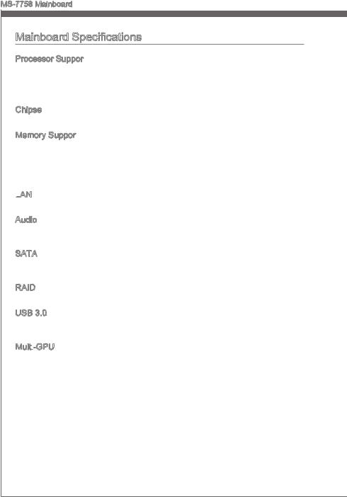
Processor Support
■Support 3rd Generation Intel® Core™ i7/ Core™ i5/ Core™ i3/ Pentium®/ Celeron® Processors for LGA 1155 socket
(For the latest information about CPU, please visit http://www.msi.com/service/cpu-support)
Chipset
■ Intel® H77 (ZH77A-G43)/ Z77 (Z77A-G43) chipset
Memory Support
■4x DDR3 DIMMs support DDR3 2667*(OC)/ 2400*(OC)/ 2133*(OC)/ 1866*(OC)/ 1600/ 1333/ 1066 DRAM (Z77A-G43, 32GB Max.)
■4x DDR3 DIMMs support DDR3 1600/ 1333/ 1066 DRAM (ZH77A-G43, 32GB Max.)
■Supports Dual-Channel mode, two DIMMs per channel
(*OC = OverClocking, please visit http://www.msi.com/service/test-report)
LAN
■ Supports LAN 10/100/1000 Fast Ethernet by Realtek® RTL8111E
Audio
■Integrated HD audio codec by Realtek® ALC892
■8-channel audio with jack sensing
SATA
■2x SATA 6Gb/s ports (SATA1~2) by Intel® H77/ Z77
■4x SATA 3Gb/s ports (SATA3~6) by Intel® H77/ Z77
RAID
■ SATA1~6 support Intel® Rapid Storage Technology (AHCI/ RAID 0/ 1/ 5/ 10)
USB 3.0
■2x USB 3.0 rear IO ports by Intel® H77/ Z77
■1x USB 3.0 onboard connector by Intel® H77/ Z77
Multi -GPU
-GPU
■ Supports AMD® CrossFire™ Technology
En-2
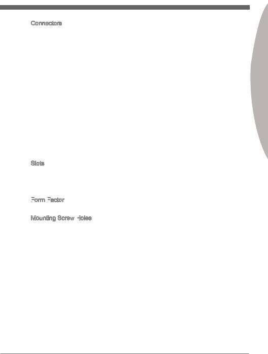
Connectors
■Back panel
—1x PS/2 keyboard/ mouse combo port
—6x USB 2.0 ports
—2x USB 3.0 ports
—1x LAN port
—1x HDMI port**, supporting a maximum resolution of 1920×1200
—1x VGA port**
—1x DVI-D port**, supporting a maximum resolution of 1920×1200
—6x audio ports
(**This mainboard supports dual-display function by any two onboard graphics output ports (HDMI+DVI,DVI+VGA or VGA+HDMI)).
■On-Board
—2x USB 2.0 connectors
—1x USB 3.0 connector
—1x TPM Module connector
—1x Serial Port connector
—1x Parallel Port connector
—1x Front Panel Audio connector
—1x Chassis Intrusion connector
—1x MultiConnect Panel connector (optinoal)
—1x Voice Genie connector (optional)
Slots
■1x PCIe 3.0 x16 slot, PCI_E2, it supports up to PCIe 3.0 x16 speed
■1x PCIe 2.0 x16 slot, PCI_E4, it supports up to PCIe 2.0 x4 speed
■2x PCIe 2.0 x1 slots
■3x PCI slots
Form
 Factor

■ ATX (30.5 cm X 24.4 cm)
Mounting Screw Holes
■ 9x mounting holes
If you need to purchase accessories and request the part numbers, you could search the product web page and find details on our web address http://www.msi.com/index. php
Engl shi
En-3

MS-7758 Mainboard
|
Connectors Quick Guide |
||||
|
JPWR2 |
CPU |
DIMM3 |
||
|
DIMM2 |
DIMM4 |
|||
|
SYSFAN3 |
DIMM1 |
|||
|
CPUFAN |
||||
|
SYSFAN1 |
||||
|
Back Panel |
JTURBO1 |
|||
|
JPWR1 |
||||
|
SYSFAN2 |
||||
|
JUSB3 |
||||
|
PCI_E1 |
||||
|
SYSFAN4 |
||||
|
PCI_E2 |
JBAT1 |
|||
|
PCI_E3 |
JCI1 |
|||
|
PCI1 |
||||
|
SATA1/ 2 |
||||
|
PCI_E4 |
||||
|
PCI2 |
SATA3/ 4 |
|||
|
PCI3 |
SATA5/ 6 |
|||
|
JAUD1 |
JFP2 |
|||
|
JTPM1 |
JFP1 |
|||
|
JUSB1/ 2 |
||||
|
JLPT1 |
JDLED3 |
|||
|
JCOM1 |
||||
|
En-4 |
Connectors Reference Guide
|
Port Name |
Port Type |
Page |
|
Back Panel |
En-6 |
|
|
CPU |
LGA1155 CPU Socket |
En-9 |
|
CPUFAN,SYSFAN1~4 |
Fan Power Connectors |
En-19 |
|
DIMM1~4 |
DDR3 Memory Slots |
En-14 |
|
JAUD1 |
Front Panel Audio Connector |
En-23 |
|
JBAT1 |
Clear CMOS Jumper |
En-26 |
|
JCI1 |
Chassis Intrusion Connector |
En-22 |
|
JCOM1 |
Serial Port Connector |
En-24 |
|
JDLED3 |
Voice Genie Connector |
En-25 |
|
JFP1, JFP2 |
Front Panel Connectors |
En-20 |
|
JLPT1 |
Parallel Port Connector |
En-24 |
|
JPWR1 |
ATX 24-pin Power Connector |
En-13 |
|
JPWR2 |
ATX 8-pin Power Connector |
En-13 |
|
JTPM1 |
TPM Module Connector |
En-23 |
|
JTURBO1 |
MultiConnect Panel Connector |
En-25 |
|
JUSB1~2 |
USB 2.0 Expansion Connectors |
En-22 |
|
JUSB3 |
USB 3.0 Expansion Connector |
En-21 |
|
PCI1~3 |
PCI Expansion Slots |
En-17 |
|
PCI_E2, PCI_E4 |
PCIe x16 Expansion Slots |
En-16 |
|
PCI_E1, PCI_E3 |
PCIe x1 Expansion Slots |
En-16 |
|
SATA1~2 |
SATA 6Gb/s Connectors |
En-18 |
|
SATA3~6 |
SATA 3Gb/s Connectors |
En-18 |
Engl shi
En-5
MS-7758 Mainboard
Back Panel Quick Guide
|
Mouse/Keyboard |
LAN |
VGA Port |
||
|
USB 2.0 Port |
||||
|
USB 3.0 Port |
Line-In RS-Out |
|||
|
Line-Out CS-Out |
||||
|
Mic |
SS-Out |
|
USB 2.0 Port USB 2.0 Port HDMI Port |
DVI-D Port |
Mouse/Keyboard
A combination PS/2® mouse/keyboard DIN connector for a PS/2® mouse/keyboard.
LAN

The standard RJ-45 LAN jack is for connecting to a Local Area Network (LAN).
Yellow 


 Green/ Orange
|
LED |
Color |
LED State |
Condition |
|
Left |
Yellow |
Off |
LAN link is not established. |
|
On(Steady) |
LAN link is established. |
||
|
On(flashing) |
The computer is communicating with another computer on the network. |
||
|
Right |
Green |
Off |
10 Mbits/sec data rate |
|
On |
100 Mbits/sec data rate |
||
|
Orange |
On |
1000 Mbits/sec data rate |
USB 2.0 Port
The USB 2.0 port is for attaching USB 2.0 devices such as keyboard, mouse, or other USB 2.0-compatible devices.
USB 3.0 Port
USB 3.0 port is backward-compatible with USB 2.0 devices. It supports data transfer rate up to 5 Gbit/s (SuperSpeed).
Important
In order to use USB 3.0 devices, you must connect to a USB 3.0 port. If a USB cable is used, it must be USB 3.0 compliant.
En-6
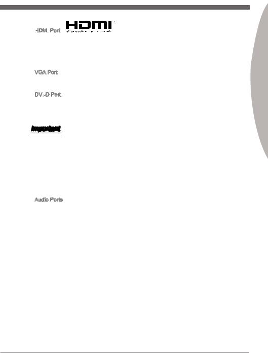
HDMI


 Port
Port
The High-Definition Multimedia Interface (HDMI) is an all-digital audio-video interface that is capable of transmitting uncompressed streams. HDMI supports all types of TV formats, including standard, enhanced, or high-definition video, plus multi-channel digital audio on a single cable.
VGA Port
The DB15-pin female connector is provided for monitor.
DVI
 -D Port
The DVI-D (Digital Visual InterfaceDigital) connector can be connected to a LCD monitor, or a CRT monitor with an adapter. To connect a monitor, please refer to the monitor’s manual for more information.
Important
This platform supports dual-display function by any two output ports (HDMI+DVI, DVI+VGA or VGA+HDMI).
|
HDMI+DVI |
DVI+VGA |
VGA+HDMI |
||
|
Extend mode |
||||
|
(Extend the desktop to the second monitor) |
||||
|
Clone mode |
||||
|
(Two monitors have the same screen) |
||||
Audio Ports
These connectors are used for audio devices. The color of the jack refers to the function of the connector.
■Blue-Line in: Used for connecting external audio outputting devices.
■GreenLine out: Used as a connector for speakers or headphone.
■PinkMic: Used as a connector for a microphone.
■Black- RS-Out: Rear surround sound line out in 4/ 5.1/ 7.1 channel mode.
■Orange- CS-Out: Center/ subwoofer line out in 5.1/ 7.1 channel mode.
■Gray- SS-Out: Side surround sound line out in 7.1 channel mode.
En-7
Engl shi
MS-7758 Mainboard
CPU (Central Processing Unit)
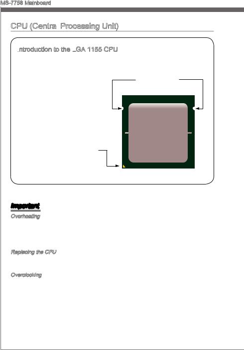
Introduction
 to the LGA
 1155 CPU
The surface of the LGA 1155 CPU has two alignment keys and a yellow triangle to assist in correctly
lining up the CPU for mainboard Alignment Key placement. The yellow triangle is the
Pin 1 indicator.
Yellow triangle is the
Pin 1 indicator
Important
Overheating
Overheating can seriously damage the CPU and mainboard. Always make sure the cooling fans work properly to protect the CPU from overheating. Be sure to apply an even layer of thermal paste (or thermal tape) between the CPU and the heatsink to enhance heat dissipation.
Replacing the CPU
When replacing the CPU, always turn off the system’s power supply and unplug the power supply’s power cord to ensure the safety of the CPU.
Overclocking
This mainboard is designed to support overclocking. Before attempting to overclock, please make sure that all other system components can tolerate overclocking. Any attempt to operate beyond product specifications is not recommend. MSI does not guarantee the damages or risks caused by inadequate operation beyond product specifications.
En-8
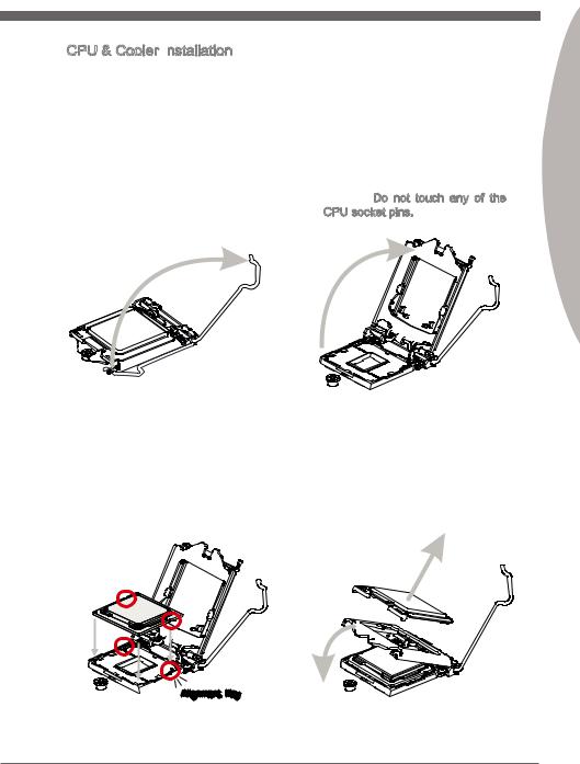
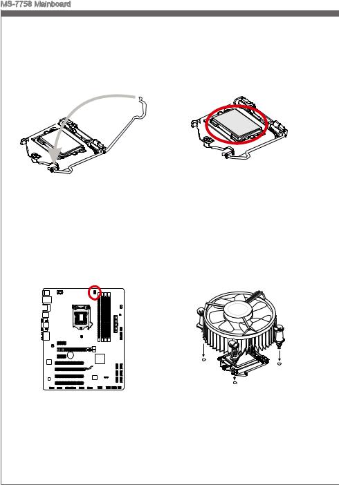
CPU & Cooler Installation

When installing a CPU, always remember to install a CPU cooler. A CPU cooler is necessary to prevent overheating and maintain system stability. Follow the steps below to ensure correct CPU and CPU cooler installation. Wrong installation can damage both the CPU and the mainboard.
|
1. Unhook and lift the loading lever to |
2. The |
loading |
plate |
should |
|
the fully open position. |
automatically lift up as the loading |
|||
|
lever is pushed to the fully open |
||||
|
position. Do not touch any of the |
||||
|
CPU socket pins. |
Engl shi
3.Line up the CPU to fit the CPU socket. Be sure to hold the CPU by the base with the metal contacts facing downward. The alignment keys on the CPU will line up with the edges of the CPU socket to ensure a correct fit.
4.Close the loading plate and remove the plastic protective cap.

 Alignment Key
En-9
MS-7758 Mainboard
5.Inspect the CPU to check if it is properly seated in the socket. Press the loading lever down and lock it under the retention tab.
7.Locate the CPU fan connector on the mainboard.
6.Evenly spread a thin layer of thermal paste (or thermal tape) on the top of the CPU. This will help in heat dissipation and prevent CPU overheating.
8.Place the heatsink on the mainboard withthefan’swiresfacingtowardsthe fanconnectorandthehooksmatching the holes on the mainboard.
En-10
![]()
9.Push down on the heatsink until the four clips get wedged into the holes on the mainboard. Press the four hooks down to fasten the cooler. As each hook locks into position a click should be heard.
10.Inspect the mainboard to ensure that the clip-ends have been properly locked in place.
Mainboard
Hook
Engl shi
11.Finally, attach the CPU fan cable to the CPU fan connector on the mainboard.
Important
•Do not touch the CPU socket pins.
•Confirm that the CPU cooler has formed a tight seal with the CPU before booting your system.
•Whenever the CPU is not installed, always protect the CPU socket pins by covering the socket with the plastic cap.
•Please refer to the documentation in the CPU cooler package for more details about CPU cooler installation.
En-11
MS-7758 Mainboard
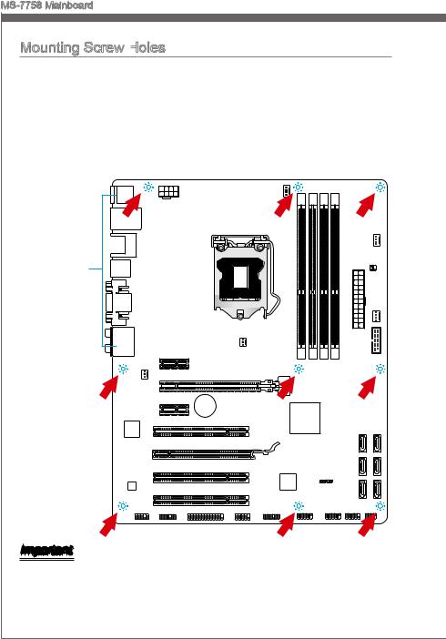
Mounting Screw Holes
When installing the mainboard, first install the necessary mounting stands required for
a mainboard on the mounting plate in your computer case. If there is an I/O back plate ngi that came with the computer case, please replace it with the I/O backplate that came
case without the need for any screws. Align the mounting plate’s mounting stands with
|
with the mainboard package. The I/O backplate should snap easily into the computer |
|
|
thi |
toward |
the screw holes on the mainboard and secure the mainboard with the screws provided
|
with your computer case. The locations of the screw holes on the mainboard are shown |
|||
|
the |
|||
|
below. For more information, please refer to the manual that came with the computer |
|||
|
case. |
holesnei |
||
|
thewonup |
|||
|
I/O |
the |
||
|
should |
I/OThe |
||
|
backplate |
the |
||
|
rear l |
|||
|
ports |
|||
|
of |
|||
|
. |
should |
||
|
computer |
|||
|
be |
|||
|
fac |
|||
|
They .case |
Important
•Install the mainboard on a flat surface free from unnecessary debris.
•To prevent damage to the mainboard, any contact between the mainboard circuitry and the computer case, except for the mounting stands, is prohibited.
•Please make sure there are no loose metal components on the mainboard or within the computer case that may cause a short circuit of the mainboard.
En-12
Power Supply
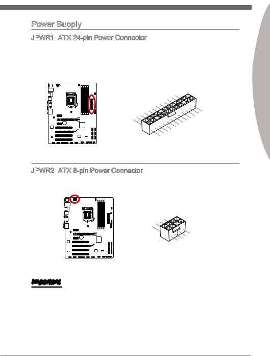
JPWR1: ATX 24-pin Power Connector

 ATX 24-pin Power Connector
This connector allows you to connect an ATX 24-pin power supply. To connect the ATX 24-pin power supply, align the power supply cable with the connector and firmly press the cable into the connector. If done correctly, the clip on the power cable should be hooked on the mainboard’s power connector.
|
12 |
||||||||||||||||||||
|
11 |
. |
|||||||||||||||||||
|
7 |
10 |
. +3. |
||||||||||||||||||
|
+12V |
||||||||||||||||||||
|
9 . |
3 |
|||||||||||||||||||
|
8 |
. |
|||||||||||||||||||
|
V |
||||||||||||||||||||
|
6 . |
||||||||||||||||||||
|
5 . |
||||||||||||||||||||
|
1 |
4 |
. +5 |
||||||||||||||||||
|
3 . |
Ground |
|||||||||||||||||||
|
2 |
. +5 |
24 |
||||||||||||||||||
|
.GroundV |
||||||||||||||||||||
|
. |
V |
|||||||||||||||||||
|
. +3 |
3 |
|||||||||||||||||||
|
+3 |
||||||||||||||||||||
|
. |
23. |
|||||||||||||||||||
|
V |
||||||||||||||||||||
|
3 |
. |
|||||||||||||||||||
|
Ground |
||||||||||||||||||||
|
. +5 |
V |
|||||||||||||||||||
|
+5 |
||||||||||||||||||||
|
+5 |
V |
V |
||||||||||||||||||
|
.Ground |
||||||||||||||||||||
|
. |
— |
|||||||||||||||||||
|
13. |
— |
ON |
||||||||||||||||||
|
+3 12V |
# |
|||||||||||||||||||
|
3 |
||||||||||||||||||||
|
V |
JPWR2: ATX 8-pin Power Connector
 ATX 8-pin Power Connector
This connector provides 12V power to the CPU.
|
4 |
||||||
|
. |
||||||
|
3 |
Ground |
|||||
|
. |
||||||
|
2 |
Ground |
|||||
|
. |
||||||
|
1 |
Ground |
|||||
|
. |
||||||
|
Ground |
||||||
|
8 |
||||||
|
5 |
. |
|||||
|
7 |
+12V |
|||||
|
. |
||||||
|
6 |
+12V |
|||||
|
. |
||||||
|
+12V |
||||||
|
. |
||||||
|
+12V |
Important
Make sure that all the power cables are securely connected to a proper ATX power supply to ensure stable operation of the mainboard.
Engl shi
En-13
MS-7758 Mainboard
En-14
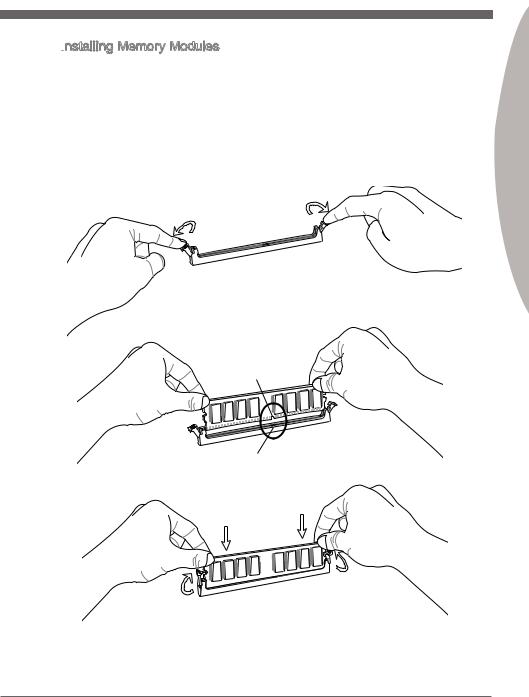
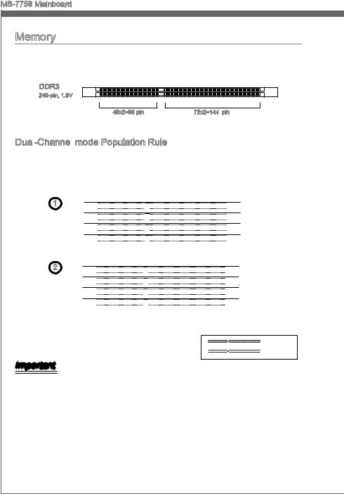
Installing Memory Modules
1.Unlock the DIMM slot by pushing the mounting clips to the side. Vertically insert the memory module into the DIMM slot. The memory module has an off-center notch on the bottom that will only allow it to fit one way into the DIMM slot.
2.Push the memory module deep into the DIMM slot. The plastic clips at each side of the DIMM slot will automatically close when the memory module is properly seat and an audible click should be heard.
3.Manually check if the memory module has been locked in place by the DIMM slot’s side clips.
Engl shi
En-15
MS-7758 Mainboard
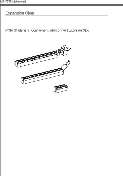
Expansion
 Slots
Slots
Thismainboardcontainsnumerousportsforexpansioncards,suchasdiscretegraphics or audio cards.
PCIe (Peripheral Component Interconnect Express) Slot
 Component Interconnect
 Express)
 Slot
SlotThe PCIe slot supports the PCIe interface expansion card.
PCIe 3.0 x16 Slot
PCIe 2.0 x16 Slot
PCIe 2.0 x1 Slot
En-16
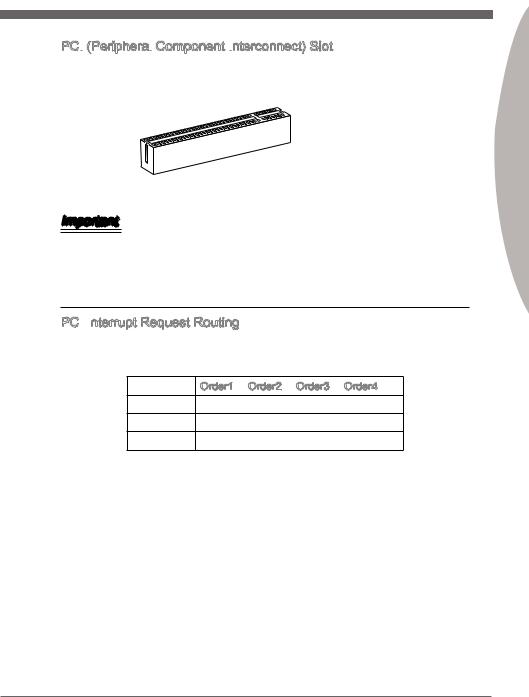
PCI (Peripheral Component Interconnect) Slot

 (Peripheral
 Component Interconnect)
 Slot
SlotThe PCI slot supports additional LAN, SCSI, USB, and other add-on cards that comply with PCI specifications.
32-bit PCI Slot
Important
When adding or removing expansion cards, always turn off the power supply and unplug the power supply power cable from the power outlet. Read the expansion card’s documentation to check for any necessary additional hardware or software changes.
PCI Interrupt
 Request Routing
IRQ, or interrupt request lines, are hardware lines over which devices can send interrupt requests to the processor. The PCI IRQ pins are typically connected to the PCI bus pins as followed:
|
Order1 |
Order2 |
Order3 |
Order4 |
|
|
PCI Slot1 |
INT A# |
INT B# |
INT C# |
INT D# |
|
PCI Slot2 |
INT B# |
INT C# |
INT D# |
INT A# |
|
PCI Slot3 |
INT C# |
INT D# |
INT A# |
INT B# |
Engl shi
En-17
MS-7758 Mainboard
Internal
 Connectors
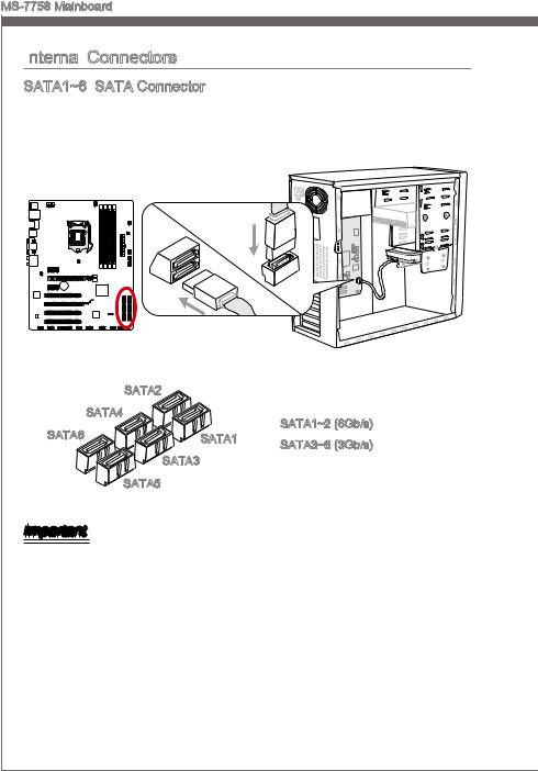
SATA1~6: SATA Connector
 SATA Connector
This connector is a high-speed SATA interface port. Each connector can connect to one SATA device. SATA devices include disk drives (HDD), solid state drives (SSD), and optical drives (CD/ DVD/ Blu-Ray).
|
* The MB layout in this figure is for reference only. |
|||
|
SATA2 |
|||
|
SATA4 |
SATA1~2 (6Gb/s) |
||
|
SATA6 |
SATA1 |
||
|
SATA3~6 (3Gb/s) |
|||
|
SATA3 |
|||
|
SATA5 |
Important
•Many SATA devices also need a power cable from the power supply. Such devices include disk drives (HDD), solid state drives (SSD), and optical drives (CD / DVD / Blu-Ray). Please refer to the device’s manual for further information.
•Many computer cases also require that large SATA devices, such as HDDs, SSDs, and optical drives, be screwed down into the case. Refer to the manual that came with your computer case or your SATA device for further installation instructions.
•Please do not fold the SATA cable at a 90-degree angle. Data loss may result during transmission otherwise.
•SATA cables have identical plugs on either sides of the cable. However, it is recommended that the flat connector be connected to the mainboard for space saving purposes.
En-18
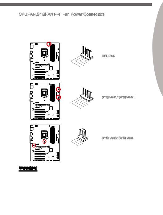
CPUFAN,SYSFAN1~4: Fan Power Connectors
 Fan
Fan Power Connectors
The fan power connectors support system cooling fans with +12V. If the mainboard has a System Hardware Monitor chipset on-board, you must use a specially designed fan with a speed sensor to take advantage of the CPU fan control. Remember to connect all system fans. Some system fans may not connect to the mainboard and will instead connect to the power supply directly. A system fan can be plugged into any available system fan connector.
CPUFAN
|
1 |
||||||||||||||||||||
|
2 . |
||||||||||||||||||||
|
. G |
||||||||||||||||||||
|
3 |
+ r |
|||||||||||||||||||
|
4 |
. |
1 o |
||||||||||||||||||
|
S |
2 u |
|||||||||||||||||||
|
. |
e |
n |
||||||||||||||||||
|
C |
n V |
d |
||||||||||||||||||
|
o |
s |
|||||||||||||||||||
|
n |
o |
|||||||||||||||||||
|
t |
r |
|||||||||||||||||||
|
r |
||||||||||||||||||||
|
o |
||||||||||||||||||||
|
l |
||||||||||||||||||||
SYSFAN1/ SYSFAN2
|
1 |
||||||||
|
2 . |
||||||||
|
3 . |
Ground |
|||||||
|
No Control |
||||||||
|
4 . |
||||||||
|
. |
Sensor |
|||||||
|
us |
||||||||
|
e |
||||||||
SYSFAN3/ SYSFAN4
|
1 |
||||||||
|
2 . |
||||||||
|
Ground |
||||||||
|
3 . |
||||||||
|
. FA |
||||||||
|
Sensor/ |
||||||||
|
N |
||||||||
|
V |
||||||||
|
oltage |
||||||||
|
N |
||||||||
|
U |
||||||||
|
se |
Important
•Please refer to your processor’s official website or consult your vendor to find recommended CPU cooling fans.
•The CPUFAN connector supports Smart Fan Control with linear mode. The Control Center II utility can be installed to automatically control the fan speeds according to the CPU’s temperature.
•If there are not enough ports on the mainboard to connect all system fans, adapters are available to connect a fan directly to a power supply.
•Before first boot up, ensure that there are no cables impeding any fan blades.
Engl shi
En-19
MS-7758 Mainboard
|
Speaker |
6 |
+ |
|||
|
Buzzer |
|||||
|
8 |
|||||
|
. |
|||||
|
4 |
. |
||||
|
— |
|||||
|
2 |
. |
||||
|
+ |
|||||
|
. |
|||||
|
— |
JFP2
|
7 |
||||||
|
3 |
5 . |
|||||
|
. No |
||||||
|
. |
Power |
|||||
|
Pi |
D |
|||||
|
1 |
Suspend |
|||||
|
. |
n |
|||||
|
Ground |
LE |
|||||
|
LE |
||||||
|
D |
|
P |
||||||||||||
|
P |
ower |
S |
10 |
|||||||||
|
witch |
No |
|||||||||||
|
ower |
||||||||||||
|
. |
Pi |
|||||||||||
|
LE |
8 |
|||||||||||
|
D |
n |
|||||||||||
|
6 |
— |
|||||||||||
|
4 |
. |
. |
||||||||||
|
+ |
||||||||||||
|
2 |
. |
|||||||||||
|
— |
||||||||||||
|
. |
||||||||||||
|
+ |
JFP1
|
9 |
|||||||||||||
|
1 |
. |
||||||||||||
|
7 |
Reserve |
||||||||||||
|
5 |
. |
||||||||||||
|
+ |
|||||||||||||
|
3 |
. |
||||||||||||
|
— |
|||||||||||||
|
. |
|||||||||||||
|
. |
— |
Reset |
d |
||||||||||
|
+ |
|||||||||||||
|
HDD |
|||||||||||||
|
LE |
S |
||||||||||||
|
D |
witch |
Important
•On the connectors coming from the case, pins marked by small triangles are positive wires. Please use the diagrams above and the writing on the mConnectors to determine correct connector orientation and placement.
•The majority of the computer case’s front panel connectors will primarily be plugged into JFP1.
En-20
![]()
JUSB3: USB 3.0 Expansion Connector

 USB 3.0 Expansion
 Connector
The USB 3.0 port is backwards compatible with USB 2.0 devices. It supports data transfer rates up to 5Gbits/s (SuperSpeed).
Engl shi
11
|
20. |
|||||||||||
|
19. |
N |
P |
|||||||||
|
18. |
|||||||||||
|
16.. |
Power |
n |
|||||||||
|
15 |
17 |
USB3 |
i |
||||||||
|
. |
_ |
||||||||||
|
13. |
USB3 |
_ |
|||||||||
|
USB3Ground |
_ |
||||||||||
|
14. |
R |
||||||||||
|
12. |
USB3 |
_ |
R |
X |
|||||||
|
C |
|||||||||||
|
Ground |
TX |
||||||||||
|
USUSB2 |
_ TX |
_ |
|||||||||
|
_ |
|||||||||||
|
. |
|||||||||||
|
B . |
C |
||||||||||
|
2 |
0 |
_ |
|||||||||
|
0 |
— |
D |
|||||||||
|
. |
|||||||||||
|
+ |
|
1 |
|||||||||||||||||
|
. |
|||||||||||||||||
|
. Po |
wer |
||||||||||||||||
|
U |
|||||||||||||||||
|
SB3_ |
|||||||||||||||||
|
SB3 |
R |
||||||||||||||||
|
SB3Ground |
_ |
X |
X |
||||||||||||||
|
U |
SB3 |
R |
_ |
||||||||||||||
|
_ |
D |
DN |
|||||||||||||||
|
. |
. |
Ground |
C |
_ |
|||||||||||||
|
TX |
P |
||||||||||||||||
|
SBSB2. |
_ |
TX_ |
|||||||||||||||
|
_ |
|||||||||||||||||
|
Ground |
C |
_ |
|||||||||||||||
|
2 |
0 |
||||||||||||||||
|
. |
D DN |
||||||||||||||||
|
0 |
— |
_ |
P |
||||||||||||||
|
+ |
* The MB layout in this figure is for reference only.
USB 3.0 Bracket (optional)
Important
•Note that the VCC and GND pins must be connected correctly to avoid possible damage.
•To use a USB 3.0 device, you must connect the device to a USB 3.0 port through an optional USB 3.0 compliant cable.
En-21

MS-7758 Mainboard
JUSB1~2: USB 2.0 Expansion Connectors

 USB 2.0 Expansion
 Connectors
This connector is designed for connecting high-speed USB peripherals such as USB HDDs, digital cameras, MP3 players, printers, modems, and many others.
|
10 |
||||||
|
6 |
8 . |
|||||
|
. |
. NC |
|||||
|
USB1Ground |
||||||
|
4 |
. |
|||||
|
. |
+ |
|||||
|
VCUSB1 |
||||||
|
2 |
||||||
|
C |
— |
|
9 |
|||||||
|
5 |
. |
||||||
|
. No |
|||||||
|
7 |
|||||||
|
. |
USB0Ground |
||||||
|
Pin |
|||||||
|
3 . |
+ |
||||||
|
VCUSB0 |
|||||||
|
1 |
|||||||
|
. |
C |
||||||
|
— |
* The MB layout in this figure is for reference only.
USB 2.0 Bracket (optional)
Important
Note that the VCC and GND pins must be connected correctly to avoid possible damage.
JCI1: Chassis Intrusion Connector
 Chassis Intrusion
 Connector
This connector connects to the chassis intrusion switch cable. If the computer case is opened, the chassis intrusion mechanism will be activated. The system will record this intrusion and a warning message will flash on screen. To clear the warning, you must enter the BIOS utility and clear the record.
|
2 |
|||||||||||||||||||
|
. |
|||||||||||||||||||
|
1 |
G |
||||||||||||||||||
|
. |
r |
||||||||||||||||||
|
C |
o |
||||||||||||||||||
|
I |
u |
||||||||||||||||||
|
N |
n |
||||||||||||||||||
|
T |
d |
||||||||||||||||||
|
R |
|||||||||||||||||||
|
U |
En-22

JAUD1: Front Panel Audio Connector
 Front
Front
 Panel
Panel Audio Connector
This connector allows you to connect the front audio panel located on your computer case. This connector is compliant with the Intel® Front Panel I/O Connectivity Design Guide.
|
10 |
||||||||||||||||
|
8 . |
||||||||||||||||
|
4 |
. NoHead |
|||||||||||||||
|
6 . |
||||||||||||||||
|
. MI |
Pi |
P |
||||||||||||||
|
NC |
D |
hone |
||||||||||||||
|
2 |
C n |
|||||||||||||||
|
. |
||||||||||||||||
|
Ground |
etection |
Detection |
||||||||||||||
|
9 |
||||||||||
|
3 . |
. |
|||||||||
|
Head |
||||||||||
|
7 |
||||||||||
|
5 . |
||||||||||
|
. |
HeadSENSE |
P |
||||||||
|
. MI |
P |
hone |
||||||||
|
MI |
||||||||||
|
1 |
C |
_ |
||||||||
|
C |
R |
SEN |
||||||||
|
hone |
D |
|||||||||
|
L |
L |
|||||||||
|
R |
||||||||||
JTPM1:
 TPM Module Connector
This connector connects to a TPM (Trusted Platform Module). Please refer to the TPM security platform manual for more details and usages.
TPM module is optional
Engl shi
|
14. |
||||||||||||||||||||
|
1012. |
||||||||||||||||||||
|
4 |
6 . |
No Ground |
||||||||||||||||||
|
. 5V |
GroundP |
|||||||||||||||||||
|
. |
8 . |
|||||||||||||||||||
|
Serial |
||||||||||||||||||||
|
. |
P in |
|||||||||||||||||||
|
3V |
Iower |
|||||||||||||||||||
|
3 |
||||||||||||||||||||
|
2 . |
||||||||||||||||||||
|
3V St P |
RQ |
|||||||||||||||||||
|
ower |
||||||||||||||||||||
|
andby |
p |
|||||||||||||||||||
|
ower |
|
13. |
||||||||||||||||||||||
|
5 |
911. |
LP |
F |
|||||||||||||||||||
|
. LP |
LPC |
|||||||||||||||||||||
|
1 |
7 . |
a |
C |
rame |
||||||||||||||||||
|
3 |
LP |
a |
||||||||||||||||||||
|
. |
Ca |
C |
a |
|||||||||||||||||||
|
. LP |
ddres |
|||||||||||||||||||||
|
. |
C |
ddres |
||||||||||||||||||||
|
LP |
C |
s |
d |
|||||||||||||||||||
|
C |
ddres |
s |
& |
|||||||||||||||||||
|
C |
R |
s |
& |
ata |
||||||||||||||||||
|
eset |
s |
& |
||||||||||||||||||||
|
lock |
& |
d |
ata |
p |
||||||||||||||||||
|
d |
at |
p |
in3 |
|||||||||||||||||||
|
at |
a |
|||||||||||||||||||||
|
a |
p in2 |
|||||||||||||||||||||
|
p in1 |
||||||||||||||||||||||
|
in0 |
* The MB layout in this figure is for reference only.
En-23

MS-7758 Mainboard
JCOM1: Serial Port Connector

 Serial
 Port Connector
This connector is a 16550A high speed communication port that sends/receives 16 bytes FIFOs. You can attach a serial device.
|
1 |
||||||||||
|
0 |
||||||||||
|
8 . |
||||||||||
|
6 |
. N |
|||||||||
|
C |
o |
|||||||||
|
. |
T |
P |
||||||||
|
4 |
D |
S |
i |
|||||||
|
S |
n |
|||||||||
|
2 |
. |
|||||||||
|
D |
R |
|||||||||
|
. |
T |
|||||||||
|
S |
R |
|||||||||
|
I |
||||||||||
|
N |
|
9 |
|||||||||
|
7 |
. |
||||||||
|
R |
|||||||||
|
5 |
. |
I |
|||||||
|
3 |
R |
||||||||
|
G |
T |
||||||||
|
. |
. |
r |
S |
||||||
|
1 |
|||||||||
|
S |
o |
||||||||
|
. |
O |
u |
|||||||
|
D |
U |
n |
|||||||
|
C |
d |
||||||||
|
T |
|||||||||
|
D |
JLPT1: Parallel Port Connector
 Parallel
 Port Connector
This connector is used to connect an optional parallel port bracket. The parallel port is a standard printer port that supports Enhanced Parallel Port (EPP) and Extended Capabilities Parallel Port (ECP) mode.
|
2 |
|||||||||||||||||||||||||||||||||||||||||||||||||||||||||||||||||||||||
|
6 |
|||||||||||||||||||||||||||||||||||||||||||||||||||||||||||||||||||||||
|
2 . |
|||||||||||||||||||||||||||||||||||||||||||||||||||||||||||||||||||||||
|
4 |
N |
||||||||||||||||||||||||||||||||||||||||||||||||||||||||||||||||||||||
|
2 . |
o |
||||||||||||||||||||||||||||||||||||||||||||||||||||||||||||||||||||||
|
2 |
2 |
G |
P |
||||||||||||||||||||||||||||||||||||||||||||||||||||||||||||||||||||
|
. |
r |
||||||||||||||||||||||||||||||||||||||||||||||||||||||||||||||||||||||
|
1 |
0 |
G |
o |
n |
|||||||||||||||||||||||||||||||||||||||||||||||||||||||||||||||||||
|
. |
r |
u |
|||||||||||||||||||||||||||||||||||||||||||||||||||||||||||||||||||||
|
1 |
8 |
G |
o |
n |
|||||||||||||||||||||||||||||||||||||||||||||||||||||||||||||||||||
|
. |
r |
u |
d |
||||||||||||||||||||||||||||||||||||||||||||||||||||||||||||||||||||
|
6 |
G |
o |
n |
||||||||||||||||||||||||||||||||||||||||||||||||||||||||||||||||||||
|
1 |
. |
r |
u |
d |
|||||||||||||||||||||||||||||||||||||||||||||||||||||||||||||||||||
|
G |
o |
n |
|||||||||||||||||||||||||||||||||||||||||||||||||||||||||||||||||||||
|
1 |
4 |
u |
|||||||||||||||||||||||||||||||||||||||||||||||||||||||||||||||||||||
|
. |
r |
n |
d |
||||||||||||||||||||||||||||||||||||||||||||||||||||||||||||||||||||
|
1 |
2 |
G |
o |
||||||||||||||||||||||||||||||||||||||||||||||||||||||||||||||||||||
|
. |
r |
u |
d |
||||||||||||||||||||||||||||||||||||||||||||||||||||||||||||||||||||
|
. G |
o |
n |
|||||||||||||||||||||||||||||||||||||||||||||||||||||||||||||||||||||
|
8 |
0 |
r |
|||||||||||||||||||||||||||||||||||||||||||||||||||||||||||||||||||||
|
G |
u |
d |
|||||||||||||||||||||||||||||||||||||||||||||||||||||||||||||||||||||
|
6 |
. |
o |
n |
||||||||||||||||||||||||||||||||||||||||||||||||||||||||||||||||||||
|
L |
o u |
d |
|||||||||||||||||||||||||||||||||||||||||||||||||||||||||||||||||||||
|
. |
P |
r |
n |
||||||||||||||||||||||||||||||||||||||||||||||||||||||||||||||||||||
|
4 |
u |
||||||||||||||||||||||||||||||||||||||||||||||||||||||||||||||||||||||
|
P |
T |
d |
|||||||||||||||||||||||||||||||||||||||||||||||||||||||||||||||||||||
|
. |
I |
_ |
n |
2 |
|||||||||||||||||||||||||||||||||||||||||||||||||||||||||||||||||||
|
E |
N |
d |
|||||||||||||||||||||||||||||||||||||||||||||||||||||||||||||||||||||
|
2 |
I |
S |
5 |
||||||||||||||||||||||||||||||||||||||||||||||||||||||||||||||||||||
|
R |
T |
L |
2 |
. |
|||||||||||||||||||||||||||||||||||||||||||||||||||||||||||||||||||
|
. |
S |
||||||||||||||||||||||||||||||||||||||||||||||||||||||||||||||||||||||
|
A |
R |
# |
I |
2 |
3 |
||||||||||||||||||||||||||||||||||||||||||||||||||||||||||||||||||
|
F |
# |
N |
. |
L |
|||||||||||||||||||||||||||||||||||||||||||||||||||||||||||||||||||
|
D |
# |
1 |
1 |
P |
C |
||||||||||||||||||||||||||||||||||||||||||||||||||||||||||||||||||
|
. |
E |
T |
|||||||||||||||||||||||||||||||||||||||||||||||||||||||||||||||||||||
|
# |
9 |
B |
|||||||||||||||||||||||||||||||||||||||||||||||||||||||||||||||||||||
|
1 . |
U |
||||||||||||||||||||||||||||||||||||||||||||||||||||||||||||||||||||||
|
7 |
A |
S |
|||||||||||||||||||||||||||||||||||||||||||||||||||||||||||||||||||||
|
1 . |
C |
||||||||||||||||||||||||||||||||||||||||||||||||||||||||||||||||||||||
|
1 |
5 |
P |
K |
Y |
|||||||||||||||||||||||||||||||||||||||||||||||||||||||||||||||||||
|
. |
R |
||||||||||||||||||||||||||||||||||||||||||||||||||||||||||||||||||||||
|
3 |
P |
# |
|||||||||||||||||||||||||||||||||||||||||||||||||||||||||||||||||||||
|
1 . |
R N |
||||||||||||||||||||||||||||||||||||||||||||||||||||||||||||||||||||||
|
1 |
P |
N |
D |
||||||||||||||||||||||||||||||||||||||||||||||||||||||||||||||||||||
|
9 . |
R |
7 |
|||||||||||||||||||||||||||||||||||||||||||||||||||||||||||||||||||||
|
7 |
. |
P |
N |
D |
|||||||||||||||||||||||||||||||||||||||||||||||||||||||||||||||||||
|
P |
R |
6 |
|||||||||||||||||||||||||||||||||||||||||||||||||||||||||||||||||||||
|
5 |
. |
R |
N |
D |
|||||||||||||||||||||||||||||||||||||||||||||||||||||||||||||||||||
|
P |
5 |
||||||||||||||||||||||||||||||||||||||||||||||||||||||||||||||||||||||
|
3 |
. |
R |
N |
D |
|||||||||||||||||||||||||||||||||||||||||||||||||||||||||||||||||||
|
P |
D |
4 |
|||||||||||||||||||||||||||||||||||||||||||||||||||||||||||||||||||||
|
1 |
. |
R |
N |
3 |
|||||||||||||||||||||||||||||||||||||||||||||||||||||||||||||||||||
|
P |
D |
||||||||||||||||||||||||||||||||||||||||||||||||||||||||||||||||||||||
|
. |
R |
N |
2 |
||||||||||||||||||||||||||||||||||||||||||||||||||||||||||||||||||||
|
R |
N |
D |
|||||||||||||||||||||||||||||||||||||||||||||||||||||||||||||||||||||
|
S |
D |
1 |
|||||||||||||||||||||||||||||||||||||||||||||||||||||||||||||||||||||
|
T |
|||||||||||||||||||||||||||||||||||||||||||||||||||||||||||||||||||||||
|
B |
0 |
||||||||||||||||||||||||||||||||||||||||||||||||||||||||||||||||||||||
|
# |
En-24

JDLED3: Voice Genie Connector (optional)

 Voice Genie Connector (optional)
This connector is used to link to the voice control module (optional). Please refer to its user guide for more details and usages.
|
14 |
|||||||||||||||||||||||||||
|
12 |
. |
||||||||||||||||||||||||||
|
. |
Contro |
||||||||||||||||||||||||||
|
10 |
. |
||||||||||||||||||||||||||
|
4 . |
Control p |
||||||||||||||||||||||||||
|
6 |
8 . |
l |
|||||||||||||||||||||||||
|
2 |
No |
||||||||||||||||||||||||||
|
. |
Control |
in |
in |
||||||||||||||||||||||||
|
. |
VCC3 |
Pin |
p |
||||||||||||||||||||||||
|
p |
|||||||||||||||||||||||||||
|
Control |
|||||||||||||||||||||||||||
|
Control |
p |
in |
|||||||||||||||||||||||||
|
p |
in |
13 |
|||||||||||||||||||||||||
|
in |
|||||||||||||||||||||||||||
|
11 |
. |
||||||||||||||||||||||||||
|
5 |
. |
Ground |
|||||||||||||||||||||||||
|
. |
9 . |
||||||||||||||||||||||||||
|
. |
|||||||||||||||||||||||||||
|
. |
7 |
Ground |
|||||||||||||||||||||||||
|
Control |
|||||||||||||||||||||||||||
|
3 . |
p |
pin |
|||||||||||||||||||||||||
|
1 |
Control |
d |
|||||||||||||||||||||||||
|
Control |
|||||||||||||||||||||||||||
|
p in |
|||||||||||||||||||||||||||
|
5VSB |
p |
in |
|||||||||||||||||||||||||
|
in |
JTURBO1: MultiConnect Panel Connector (optional)
 MultiConnect Panel
 Connector (optional)
ThisconnectorisusedtoconnectanoptionalfrontpanelforcontrolingtheOCGenieand some additional functions. Please refer to its user guide for more details and usages.
|
2 |
|||||||||
|
1 . |
|||||||||
|
Ground |
|||||||||
|
. |
|||||||||
|
TURB |
O |
||||||||
|
4 |
||
|
. |
||
|
. No |
||
|
3 |
||
|
TURB |
||
|
Pi |
||
|
n |
||
|
O |
Engl shi
En-25

MS-7758 Mainboard
Jumper
JBAT1: Clear CMOS Jumper

 Clear CMOS Jumper
There is CMOS RAM onboard that is external powered from a battery located on the mainboard to save system configuration data. With the CMOS RAM, the system can automatically boot into the operating system (OS) every time it is turned on. If you want to clear the system configuration, set the jumpers to clear the CMOS RAM.
1 1
Keep Data Clear Data
Important
YoucancleartheCMOSRAMbyshortingthisjumperwhilethesystemisoff.Afterwards, open the jumper . Do not clear the CMOS RAM while the system is on because it will damage the mainboard.
En-26

BIOS Setup
CLICK BIOS II is developed by MSI that provides a graphical user interface for setting parameters of BIOS by using the mouse and the keybord.
With the CLICK BIOS II, users can change BIOS settings, monitor CPU temperature, select the boot device priority and view system information such as the CPU name, DRAM capacity, the OS version and the BIOS version. Users can import and export parameters data for backup or sharing with friends. After connecting to Internet, users can browse the internet, check mail and live update your system.
Entering

Power on the computer and the system will start POST (Power On Self Test) process. When the message below appears on the screen, press <DEL> key to enter Setup.
Press DEL key to enter Setup Menu, F11
 to enter Boot Menu
If the message disappears before you respond and you still wish to enter Setup, restart the system by turning it OFF and On or pressing the RESET button. You may also restart the system by simultaneously pressing <Ctrl>, <Alt>, and <Delete> keys.
Important
The items under each BIOS category described in this chapter are under continuous update for better system performance. Therefore, the description may be slightly different from the latest BIOS and should be held for reference only.
Engl shi
En-27

MS-7758 Mainboard
Overview
After entering CLICK BIOS II, the following screen is displayed.
Temperature
monitor
Mode selection
BIOS menu selection
Menu display
System information
Boot menu
Boot device priority bar
BIOS menu selection
Important
The pictures in this guide are for reference only and may vary from the product you purchased. Please refer to the actual screens of your system for detailed information.
Temperature monitor
This block shows the temperature of the processor and the mainboard.System information
This block shows the time, date, CPU name, CPU frequency, DRAM frequency, DRAM capacity and the BIOS version.
BIOS menu selection
These blocks are used to select menus of BIOS. The following options are available:
■SETTINGS — Use this menu to specify your settings for chipset features, boot device.
■OC — This menu contains items of the frequency and voltage adjustments. Increasing the frequency can get better performance, however high frequency and heat can cause instability, we do not recommend general users to overclock.
■ECO
 — This menu is related to energy-saving settings.
■BROWSER — This feature is used to enter the MSI Winki web browser.
■UTILITIES — This menu contains utilities for backup and update.
■SECURITY — The security menu is used to keep unauthorized people from making any changes to the settings. You can use these security features to protect your system.
En-28

Boot device priority bar
You can move the device icons to change the boot priority.Boot menu
This button is used to open a boot menu. Click the item to boot the system from the device instantly.
Mode selection
This feature allows you to load presets of energy saving or overclocking.Menu display
This area provides BIOS setting menu that allows you to change parameters.
Boot device priority bar
This bar shows the priority of the boot devices. The light icons indicate that the devices are available.
High priority  Low priority Click and draw the icon to left or right to specify the boot priority.
Sub-Menu
An arrow symbol appears to the left of certain fields that means it contains a sub-menu. A sub-menu contains additional options for a field parameter. You can use arrow keys ( ↑↓ ) or mouse to highlight the field and press <Enter> or mouse double left click to enter the sub-menu. If you want to return to the previous menu, just press the <Esc > or click the right mouse button.
General
 Help
Help

CLICK BIOS II provides General Help window. You can call up the window from any BIOS menu by simply pressing <F1> or click HELP on BIOS setting screen. The Help window lists the appropriate keys to use and the possible selections for the highlighted item.
Engl shi
En-29

MS-7758 Mainboard
Operation
CLICK BIOS II allows you to control BIOS settings with the mouse and the keyboard. The following table lists and describes the hot keys and the mouse operations.
|
Hot key |
Mouse |
Description |
|
<↑↓→← > |
Select Item |
|
|
Move the cursor |
||
|
<Enter> |
Select Icon/ Field |
|
|
Click/ Double- |
||
|
click the left |
||
|
button |
||
|
<Esc> |
Jump to the Exit menu or return to the previous from |
|
|
a submenu |
||
|
Click the right |
||
|
button |
||
|
<+> |
Increase the numeric value or make changes |
|
|
<-> |
Decrease the numeric value or make changes |
|
|
<F1> |
General Help |
|
|
<F4> |
CPU Specifications |
|
|
<F5> |
Enter Memory-Z |
|
|
<F6> |
Load optimized defaults |
|
|
<F10> |
Save Change and Reset |
|
|
<F12> |
Save a screenshot to a FAT/FAT32 USB drive |
En-30
![]()
OC Menu
This menu is for advanced users who want to overclock the mainboard.
Engl shi
Important
•Overclocking your PC manually is only recommended for advanced users.
•Overclocking is not guaranteed, and if done improperly, can void your warranty or severely damage your hardware.
•If you are unfamiliar with overclocking, we advise you to use OC Genie for easy overclocking.
Current CPU/ DRAM Frequency

These items show the current clocks of CPU and Memory speed. Read-only.Adjust CPU Ratio
Controls the multiplier that is used to determine internal clock speed of the processor. This feature can only be changed if the processor supports this function.
Adjusted CPU Frequency

It shows the adjusted CPU frequency. Read-only.
Adjust CPU Ratio in OS
OS
Enable this item to allow CPU ratio changes in the OS by using MSI Control Center II.
Internal


 PLL Overvoltage
This item is used to adjust the PLL voltage.
En-31

MS-7758 Mainboard
EIST


Enhanced Intel SpeedStep technology allows you to set the performance level of the microprocessor whether the computer is running on battery or AC power. This field only appears with installed CPUs that support this technology.
Intel

 Turbo Boost
Enables or disables Intel Turbo Boost which automatically boosts CPU performance above rated specifications (when applications requests the highest performance state of the processor).
OC Genie Button Operation
This item allows you to enable/disable the OC Genie function.
DRAM Frequency

This item allows you to adjust the DRAM frequency. Please note the overclocking behavior is not guaranteed.
Adjusted DRAM Frequency

It shows the adjusted DRAM frequency. Read-only.
DRAM Timing Mode
Select whether DRAM timing is controlled by the SPD (Serial Presence Detect) EEPROM on the DRAM module. Setting to [Auto] enables DRAM timings and the following “Advanced DRAM Configuration” sub-menu to be determined by BIOS based on the configurations on the SPD. Selecting [Link] or [Unlink] allows users to configure the DRAM timings for each channel and the following related “Advanced DRAM Configuration” sub-menu manually.
Advanced DRAM Configuration
Press <Enter> to enter the sub-menu.
Command Rate
This setting controls the DRAM command rate.
tCL
Controls CAS latency which determines the timing delay (in clock cycles) of starting a read command after receiving data.
tRCD
Determines the timing of the transition from RAS (row address strobe) to CAS (column address strobe). The less clock cycles, the faster the DRAM performance.
tRP
Controls number of cycles for RAS (row address strobe) to be allowed to pre-charge. If insufficient time is allowed for RAS to accumulate before DRAM refresh, the DRAM may fail to retain data. This item applies only when synchronous DRAM is installed in the system.
En-32

tRAS
Determines the time RAS (row address strobe) takes to read from and write to memory cell.
tRFC
This setting determines the time RFC takes to read from and write to a memory cell.
tWR
Determines minimum time interval between end of write data burst and the start of a pre-charge command. Allows sense amplifiers to restore data to cell.
tWTR
Determines minimum time interval between the end of write data burst and the start of a column-read command; allows I/O gating to overdrive sense amplifies before read command starts.
tRRD
Specifies the active-to-active delay of different banks.
tRTP
Time interval between a read and a precharge command.tFAW
This item is used to set the tFAW (four activate window delay) timing.tWCL
This item is used to set the tWCL (Write CAS Latency) timing.
Advanced Channel 1/ 2 Timing Configuration
Press <Enter> to enter the sub-menu. And you can set the advanced memory timing for each channel.
GT OverClocking
This item allows you to enable/ disable the overclocking of integrated graphics.GT Ratio
Ratio
This setting controls the ratio of integrated graphics frequency to enable the integrated graphics to run at different frequency combinations.
Adjusted GT Frequency
t shows the iGPU frequency. Read-only.
Engl shi
En-33

MS-7758 Mainboard
Spread Spectrum
This function reduces the EMI (Electromagnetic Interference) generated by modulating clock generator pulses.
Important
•If you do not have any EMI problem, leave the setting at [Disabled] for optimal system stability and performance. But if you are plagued by EMI, select the value of Spread Spectrum for EMI reduction.
•The greater the Spread Spectrum value is, the greater the EMI is reduced, and the systemwillbecomelessstable.ForthemostsuitableSpreadSpectrumvalue, please consult your local EMI regulation.
•Remember to disable Spread Spectrum if you are overclocking because even a slight jitter can introduce a temporary boost in clock speed which may just cause your overclocked processor to lock up.
CPU Core Voltage/ DRAM Voltage.
These items are used to adjust the voltage of CPU and Memory.
Current CPU Core Voltage/ Current DRAM Voltage These items show current CPU/ DRAM voltage. Read-only.
Overclocking Profiles
Press <Enter> to enter the sub-menu.
Overclocking Profile 1/ 2/ 3/ 4/ 5/ 6 Press <Enter> to enter the sub-menu.
Set Name for Overclocking Profile 1/ 2/ 3/ 4/ 5/ 6 Give a name by typing in this item.
Save Overclocking Profile 1/ 2/ 3/ 4/ 5/ 6
Save the current overclocking settings to ROM for selected profile.
Load/ Clear Overclocking Profile 1/ 2/ 3/ 4/ 5/ 6 Load/ Clear the stored profile settings from ROM.
OC Profile Save to USB
Save the current overclocking settings to USB flash disk.
OC Profile Load
 from USB
Load the stored settings from USB flash disk.
En-34

CPU Specifications
Press <Enter> to enter the sub-menu. This sub-menu highlights all the key features of your CPU. The information will vary by model and is read-only. You can also access this information at any time by pressing [F4]. Press <Enter> to enter the sub-menu.
CPU Technology Support
Press <Enter> to enter the sub-menu. The sub-menu shows the installed CPU technologies. Read only.
MEMORY-Z
Press <Enter> to enter the sub-menu. This sub-menu highlights all the settings and timings of your DIMMs. This information will vary by model and is read-only. You can also access this information at any time by pressing [F5]. Press <Enter> to enter the sub-menu.
DIMM1~4 Memory SPD
Press <Enter> to enter the sub-menu. The sub-menu displays the informations of installed memory.
CPU Features

Press <Enter> to enter the sub-menu.
Active Processor Cores
This item allows you to select the number of active processor cores.
Limit CPUID Maximum
It is designed to limit the listed speed of the processor to older operating systems.
Execute
 Disable Bit
Can prevent certain classes of malicious “buffer overflow” attacks where worms can try to execute code to damage your system. It is recommended you keep this enabled always.
Intel
 Virtualization Tech
Enhances virtualization and allows the system to act as multiple virtual systems. See Intel’s official website for more information.
Intel
 VT
VT
 -D Tech
This item is used to enable/disable the Intel VT-D technology. For further information please refer to Intel’s official website.
Power Technology
This item allows you to select the Intel Dynamic Power technology mode.
Engl shi
En-35

MS-7758 Mainboard
C1E Support
Enable system to reduce CPU power consumption while idle. Not all processors support Enhanced Halt state (C1E).
OverSpeed Protection
Monitors current CPU draw as well as power consumption; if it exceeds a certain level, the processor automatically reduces its clock speed. For overclocking, it is recommended this feature is disabled.
Intel
 C-State
C-state is a power management state that detects when the system is idle and lowers power consumption accordingly.
Package C State limit

This field allows you to select a C-state mode.
Long duration power limit
 (W)
(W)
This field allows you to adjust the TDP power limit for the long duration.
Long duration maintained (s)
This field allows you to adjust the maintaining time for long duration power limit.
Short duration power limit
 (W)
(W)
This field allows you to adjust the TDP power limit for the short duration.Primary/ Secondary Plane Current value (A)
These fields allow you to adjust over current value of CPU (primary plane)/ iGPU (secondary plane) for turbo ratio.
Primary/ Secondary plane turbo power limit
 (W)
(W)
These fields allow you to adjust the turbo power limit of CPU (primary plane)/ iGPU (secondary plane) for turbo boost.
En-36

Updating the BIOS with Live
 Update
This section tells you how to update the BIOS by using the Live Update utility before entering Operating System. Live Update will update the BIOS automatically when connecting to the Internet. To update the BIOS with the Live Update utility:
|
1. Click Live Update button |
on the BIOS UTILITIES menu. (The Winki must be |
|
installed). |
2.Setup the connection by click the setting button if necessary.
3.Click the next button .
.
4.Live Update will automatically detect the version of BIOS and download the appropriate file.
5. Click the confirm button to update the BIOS.
Engl shi
Important
Do not update the BIOS if your system is running fine.
En-37

MS-7758 Mainboard
Software Information
Take out the Driver/Utility Disc that is included in the mainboard package, and place it into the optical drive. The installation will auto-run, simply click the driver or utility and follow the pop-up screen to complete the installation. The Driver/Utility Disc contains the:
—Driver menu : It provides available drivers. Install the driver by your desire and to activate the device.
—Utility menu : It allows you to install the available software applications.
—Service base menu : Through this menu to link the MSI officially website.
—Product info menu : It shows the newly information of MSI product.
—Security menu : It provides the useful antivirus program.
Important
Please visit the MSI officially website to get the latest drivers and BIOS for better system performance.
Installing
 Winki
Winki
BIOS BROWSER and UTILITIES request Winki, please install the «Winki» software application from MSI Driver Disc in Windows first. And then you can access these two features by clicking their respective buttons.
To install Winki, follow the steps below:
1.Power on your computer and enter Windows operating system.
2.Insert MSI Driver Disc into the optical drive. The setup screen will automatically appear.
3.Click Driver tab.
4.Click OTHERS button.
5.Select Winki to start installing.
6.When finished, restart your computer.
En-38

Deutsch
ZH77A-G43/
Z77A-G43 Serie
 Loading…