-
Contents
-
Table of Contents
-
Troubleshooting
-
Bookmarks
Quick Links
1.1-1.7-2.2-3 kVA
Installation and operating manual
GB
Related Manuals for socomec netis rt
Summary of Contents for socomec netis rt
-
Page 1
1.1-1.7-2.2-3 kVA Installation and operating manual… -
Page 2
The warranty is offered on carry-in terms: components and labour for repairs supplied free of charge, and in the case of a replace- ment, the product to be returned to SOCOMEC UPS or to authorized service centres, at the customer’s own risk and expense. -
Page 3: Table Of Contents
TABLE OF CONTENTS 1. SAFETY STANDARDS…………4 1.1 Important .
-
Page 4: Safety Standards
The use of the product in “critical applications” could require compliance with statutory regula- tions and standards, or with specific local bylaws, or adaptation to SOCOMEC UPS recommendations. For this type of use, in any event, it is advisable to contact SOCOMEC UPS beforehand for confirmation regarding the capacity of products to meet required levels of safety, performance and reliability.
-
Page 5: Description Of The Symbols Used On The Labels Applied To The Unit
1. SAFETY ISOLATE THE UPS BEFORE WORKING ON THIS CIRCUIT. External power distribution unit UPS. Legend. B Contactor solenoid. Q Mains input thermal-magnetic switch T Two-pole contactor > 30 A AC1; coil voltage: according to the Mains input. 1.2 Description of the symbols used on the labels applied to the unit All the precautions and the warnings on the labels and plates on the inside and outside of the equipment should be respected.
-
Page 6: Installation
2. INSTALLATION 2.1 Environmental requirements for installation Consult the following check list when installing the UPS: • NETYS RT units are designed for use in enclosed environments. • Position the UPS on a flat and stable surface in a properly ventilated room, well away from heat sources and avoiding direct exposure to sunlight.
-
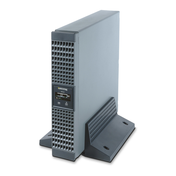
Page 7: Vertical Installation
2. INSTALLATION 2.2 Vertical installation 2.2.1 UPS Installation 2.2.2 UPS Installation with 1 battery extension 1.1-3 kVA — Ref.: IOMNETRTXX00-GB 00…
-
Page 8
2. INSTALLATION 2.2.3 UPS Installation with multiple battery extensions 1.1-3 kVA — Ref.: IOMNETRTXX00-GB 00… -
Page 9: Horizontal Installation On Rack
2. INSTALLATION 2.3 Horizontal installation on rack 2.3.1 Rotation of mimic pannel 1.1-3 kVA — Ref.: IOMNETRTXX00-GB 00…
-
Page 10
2. INSTALLATION 2.3.2 Fitting rack brackets 1.1-3 kVA — Ref.: IOMNETRTXX00-GB 00… -
Page 11
2. INSTALLATION 2.3.3 Fixing to rack 1. Adapt the length of the tracks to fit the rack. 2. Secure the wing nuts. 3. Fix the track to the rack. 4. Slot in the UPS and tighten the screws. MAX 100 kg MAX 100 kg MAX 100 kg MAX 100 kg… -
Page 12: Rear View
3. REAR VIEW 1100 VA 1700 VA 3000 VA 2200 VA Legend A Mains input socket (IEC 320) B Fan C Output socket (full power) D Telephone socket — input E Telephone socket — output F EPO (Emergency Power Off) G RS232 serial connector (JBUS protocol) H USB socket Input protection…
-
Page 13: Connections
4. CONNECTIONS Connection to the mains power supply and to the load(s) must be made using cables of suitable cross section, in accordance with current standards. If not already provided, install a PDU panel allowing isolation of the mains supply upstream of the UPS. The panel must be equipped with an automatic switch rated high enough to handle the current draw on full load, and with a residual current device.
-
Page 14: Connection Of Battery Extension
5. CONNECTION OF BATTERY EXTENSION 5.1 Safety warnings • Before connecting the battery extension, check that it is fully compatible with the model of UPS in use. • The use of battery extensions not supplied by the manufacturer is inadvisable. WARNING! There is a risk of explosion if battery modules are replaced with others of incorrect type.
-
Page 15
5. CONNECTION OF BATTERY EXTENSION Switch Switch ON-OFF ON-OFF 1100 VA 1700 VA 2200 VA 3000 VA Connection of multiple batteries 1.1-3 kVA — Ref.: IOMNETRTXX00-GB 00… -
Page 16: Mimic Panel
6. MIMIC PANEL The mimic panel on the front of the UPS provides all essential information on the operating status of the appliance. Legend A Yellow LED — Operation in by-pass mode. B 2 colour LEDs: • Green — Stand-alone mode (battery power) •…
-
Page 17: Operating Modes
7. OPERATING MODES 7.1 Battery recharge Connect the UPS to the mains voltage for approximately 8 hours to recharge the internal batteries. The UPS can be used even with the batteries not fully charged, though if a power outage should occur, the duration of the backup will be shorter.
-
Page 18: Battery Test
7. OPERATING MODES 7.2.3 Switching off with mains present 7.2.3-1 7.2.3-2 7.2.3-3 Normal operation. • UPS is off but battery remains on short charge • Shut down all loads, one at a time. • Switch off mains power to shut down completely.
-
Page 19: Rated Output Voltage Setting
7. OPERATING MODES 7.3 Rated Output Voltage Setting 7.3-1 7.3-2 7.3-3 Standby mode. 230 Vac mode. 1 sec 7.3-4 230 Vac mode. 240 Vac mode. • Press ON/TEST button to choose the Rated Output Voltage. 200 Vac mode 208 Vac mode. 220 Vac mode.
-
Page 20: Visual And Audible Warning Signals
8. VISUAL AND AUDIBLE WARNING SIGNALS By-pass mode. Overload. Short-circuit on output. continuous continuous Battery needs replacing. Battery flat. Shutdown caused by flat battery. 1 Short every 2 seconds 1 long every 1.25 seconds Overtemperature. Battery charge failure. Fan failure. continuous 1 long 2 short every 4.2 seconds 1 short every 1 second…
-
Page 21: Communication
• UniVision local management software (RS232interface) with local shutdown functions for Windows™ and Linux systems, downloadable free of charge from the Socemec website www.socomec.com (CD included with certain models). • Uni Vision Pro network management software (RS232interface) with local/remote shutdown functions on major operating systems, using Java Shutdown Client.
-
Page 22: Standard Configuration
9. COMMUNICATION 9.5.1 Internal circuit 9.5.1-1 9.5.1-2 Common R1 General alarm R2 No mains R3 Battery low R4 On by-pass R5 Overload R6 Overtemperature CPU Pin GND-R GND-R Input 9.5.1-3 GND-R Common Input GND-C 9.5.2 Standard configuration relay contact GND-R: Relay ground contact Common: 12~24 V DC General alarm No mains…
-
Page 23
9. COMMUNICATION 9.5.3 Customized configuration for relay and/or input contacts Connect Tx to pin 2, Rx to pin 3 and GND-C to pin 5 of the computer’s RS232 port. In Windows, start the Hyper-Terminal application and proceed to open the specified COM port. Set the following properties: Baud rate: 2400, Data Bits: 8, Parity: None, Stop Bit: 1, Flow Control: None. -
Page 24: Maintenance
• Recharge the batteries for a duration of 24 hours at least every 4 weeks during the time the unit remains idle. 10.1 Minor troubleshooting WARNING! If problems should persist or reoccur frequently after following the procedures indicated in this section, contact the SOCOMEC UPS After Sales Service, providing a full description of the current difficulty Problem Possible cause Solution «UPS not powered up…
-
Page 25: Technical Specifications
11. TECHNICAL SPECIFICATIONS Models NRT-U1100 NRT-U1700 NRT-U2200 NRT-U3000 UPS power 1100 VA 1700 VA 2200 VA 3000 VA 800 W 1200 W 1600 W 2100 W Input Single-phase 230 V (160-275 V); 50/60 Hz with automatic selection Input socket IEC 320-C14 (10 A) IEC 320-C20 (16 A) Output Single-phase 230 V nominal ±2% (selectable: 200…
-
Page 26
S E R V I C E M A N A G E M E N T SOCOMEC GROUP S.A. SOCOMEC capital 11 102 300 € — R.C.S. Strasbourg B 548 500 149 SOCOMEC UPS Paris B.P. 60010 — 1, rue de Westhouse — F-67235 Benfeld Cedex…
|
Detail Specifications: 734/734210-netys_rt.pdf file (05 Apr 2023) |
Accompanying Data:
socomec Netys RT Battery Charger, UPS PDF Installation And Operating Manual (Updated: Wednesday 5th of April 2023 10:18:25 PM)
Rating: 4.4 (rated by 95 users)
Compatible devices: ITYS PRO 10, netis rt, MODULYS GP 25 kVA, Masterys Green Power, DELPHYS MX, MASTERYS BC 60 kVA, EBP, MASTERYS IP+.
Recommended Documentation:
Text Version of Installation And Operating Manual
(Ocr-Read Summary of Contents, UPD: 05 April 2023)
-
34, 34 5-11 kVA — Ref.: IOMNETRTXX01-GB 05 10. COMMUNICATION Communication software and accessories are available for monitoring the status of the UPS, with the end in view of optimizing normal operation and ensuring that shutdown at the end of backup time is managed correctly. Applications allow recording of all power outages and any depletion of battery power s…
-
20, 20 5-11 kVA — Ref.: IOMNETRTXX01-GB 05 6.2.3 Connection of cables to the UPS terminal strips 6. CONNECTION OF BY-PASS AND SINGLE UPS 3 4 1 2 074 DRWNETRT-XX 076 DRWNETRT-XX 075 DRWNETRT-XX
… -
35, 35 ENGLISH 5-11 kVA — Ref.: IOMNETRTXX01-GB 05 10.4.1 Internal circuit 10.4.2 Standard confi guration R1 R2 R3 R4 R5 Common GND-R Input +5V CPU Pin R6 GND-R Common R1 R2 R3 R4 R5 R6 Input Tx Rx GND-C SW1 SW2 GND-R R1 General alarm R2 No mains R3 Battery low R4 On by-pass R5 Overload R6 Overtemperature 10.4.1-1 10.4.1-3 10.4.1-2 SW1 SW2 relay contact OFF OFF NO ON OFF NC GND-R: Rela…
-
33, socomec Netys RT 33 ENGLISH 5-11 kVA — Ref.: IOMNETRTXX01-GB 05 9.5 OPERATION IN BY-PASS MODE — UPS IN PARALLEL FOR MAINTENANCE PURPOSES 9. OPERATING MODES A BYPASS switch C UPS1 switch D UPS2 switch B UPS output line breaker Output UPS1+UPS2 OFF ON ON ON Output UPS1 (UPS2 off for maintenance) OFF ON OFF ON Output UPS2 (UPS1 off for maintenance) OFF OFF ON ON BY-PASS…
-
17, 17 ENGLISH 5-11 kVA — Ref.: IOMNETRTXX01-GB 05 5. CONNECTION OF BATTERY EXTENSION Connection of multiple batteries ON-OFF switch ON-OFF switch 5 kVA 7 kVA 9 kVA 11 kVA COM. SLOT EPO PARALLEL RS232 SMART SLOT OUTPUT N L L INPUT N INPUT BREAKER 230Vac 40A 230Vac 50/60Hz 230Vac 50/60Hz CABLE UNDER LOAD. DO NOT DISCONNECT BATTERY EXTERNAL BATTERY CONNECTOR CAUTION: SW Netw…
-
38, 38 5-11 kVA — Ref.: IOMNETRTXX01-GB 05 12. TECHNICAL SPECIFICATIONS Models NRT2-U5000 NRT2-U7000 NRT2-U9000 NRT2-U11000 UPS power 5000 VA 4500 W 7000 VA 5400 W 9000 VA 7200 W 11000 VA 9000 W Input 230 V (1 ph) ± 20% (up to -50% at 50% nominal load) Input socket Terminals Output Single-phase 230 V nominal ±2% (selectable: 200/208/220/240 V); 50/60 Hz Output sockets Ter…
-
24, socomec Netys RT 24 5-11 kVA — Ref.: IOMNETRTXX01-GB 05 7.2 RACK INSTALLATION OF BY-PASS AND UPS IN PARALLEL 7.2.1 Fixing brackets for rack installation 7.2.2 Fitting BY-PASS to rack 7. CONNECTION OF BY-PASS AND UPS IN PARALLEL 133 DRWNETRT-XX 109 DRWNETRT-XX
… -
29, 29 ENGLISH 5-11 kVA — Ref.: IOMNETRTXX01-GB 05 9. OPERATING MODES 9.1 SWITCHING THE NETYS RT ON 9.2 SWITCHING THE NETYS RT OFF 9.1-1 171 DRWNETRT-XX 9.1-3 175 DRWNETRT-XX 3 sec 9.2-1 174 DRWNETRT-XX short 3 sec 9.2-2 177 DRWNETRT-XX short 9.1-4 171 DRWNETRT-XX 3 sec 9.1-2 172 DRWNETRT-XX short
… -
5, socomec Netys RT 5 ENGLISH 5-11 kVA — Ref.: IOMNETRTXX01-GB 05 1. SAFETY STANDARDS 1.2 DESCRIPTION OF THE SYMBOLS USED ON THE LABELS APPLIED TO THE UNIT All the precautions and the warnings on the labels and plates on the inside and outside of the equipment should be respected. DANGER! HIGH VOLTAGE (BLACK/YELLOW) GROUND TERMINAL READ THE USER MANUAL BEFORE USING THE UNIT
… -
12, socomec Netys RT 12 5-11 kVA — Ref.: IOMNETRTXX01-GB 05 MAX 100 kg MAX 100 kg MAX 100 kg MAX 100 kg 3 3 1 2 4 060 DRWNETRT-XX 066 DRWNETRT-XX 061 DRWNETRT-XX 2.4.4 Fixing to rack 1. Adapt the length of the tracks to fit the rack. 2. Secure the wing nuts. 3. Fix the track to the rack. 4. Slot in the UPS and tighten the screws. 2. INSTALLATION
…
Recommended Instructions:
Bluetooth GPS Nav Kit, VX1000, 5CO, BTS-5


-
4152 31 2 4567 8 9 10 12113 OR500LCDRM1U / OR700LCDRM1U User’s Manual K01-0000786-00 Thank you for purchasing a CyberPower product. Please take a few minutes to register your product at: www.CyberPowerSystems.com/Registration. Registration certifies your product’s warranty, confirms your ownership in the event of a product loss or theft and entitles yo …
OR500LCDRM1U 2
-
1Issue: 08Part Number: 31507342Date: 2019-04-15PDU8000 Modular Integrated PDC V1.0Quick GuideCopyright © Huawei Technologies Co., Ltd. 2019. All rights reserved.1Installing the PDC1. Mark the positions for installing the PDC based on the marking-off template. Drill holes and install expansion sleeves.Securing the PDC1.1Leveling foot Level3. Partially drive the bolts into the expansion …
PDU8000 Series 12
-
1 25,216&5N9$2N-LINE 57UPS User Manual and Instructions Table of contents 1. Introduction……………………………………………………………………..2 1.1 System Introduction ………………………………………………….2 1.2 Product Features …………………………………………………… …
SCR2 9
-
User ManualHasználati útmutató Ръководство на потребителяKorisničko uputstvoManual de utilizarev. 1Before using this product, carefully read all product documentation and retain it for future reference.Horus SeriesPWUP-LI060HR-AZ01BPWUP-LI080HR-AZ01BPWUP-LI100HR-AZ01B …
PWUP-LI060HR-AZ01B 27
Additional Information:
Popular Right Now:
Operating Impressions, Questions and Answers:
7.1 Battery recharge
Connect the UPS to the mains voltage for approximately 8 hours to recharge the internal batteries.
The UPS can be used even with the batteries not fully charged, though if a power outage should occur, the duration of the backup
will be shorter.
7.1-1
7.2 Switching the Netys RT ON and OFF
7.2.1 Switching on with mains present
7.2.1-1
Power up all loads, one at a time.
7.2.2 Switching on with no mains power
7.2.2-1
Power up all loads, one at a time.
short
3 sec
7.2.1-2
short
3 sec
7.2.2-2
Normal operation.
short
3 sec
7.2.1-3
Normal operation.
1.1-3 kVA — Ref.: IOMNETRTXX00-GB 00
17
Table of Contents for socomec Netys RT:
-
22 5-11 kVA — Ref.: IOMNETRTXX01-GB 00 6.2.5 Connection of cables to the BY-PASS input and output terminal strips 6. CONNECTION OF BY-PASS AND SINGLE UPS UPS input UPS output UPS input UPS output 1 2 080 DRWNETRT-XX 081 DRWNETRT-XX
-
7 ENGLISH 5-11 kVA — Ref.: IOMNETRTXX01-GB 00 2. INSTALLATION = = 2.3 Vertical installation 2.3.1 UPS Installation 4 4 2 1 3 031 DRWNETRT-XX 115 DRWNETRT-XX 059 DRWNETRT-XX 102 DRWNETRT-XX 103 DRWNETRT-XX
-
2 5-11 kVA — Ref.: IOMNETRTXX01-GB 00 This SOCOMEC UPS appliance is guaranteed against possible defects of manufacture and materials, for a period of 12 months from the date of purchase (local warranty conditions are applicable in addition to the general conditions). The present warranty certificate should NOT be mailed, but kept by the customer together with the proof of purchase document, for use in the event of a claim
-
6 5-11 kVA — Ref.: IOMNETRTXX01-GB 00 2. INSTALLATION 2.1 Environmental requirements for installation Consult the following check list when installing the UPS: • NETYS RT units are designed for use in enclosed environments. • Position the UPS on a flat and stable surface in a properly ventilated room, well away from heat sources and avoiding direct expo- sure to sunlight. • Ambient temperature should be maintained betwee
-
30 5-11 kVA — Ref.: IOMNETRTXX01-GB 00 9. OPERATING MODES 9.2 Operation in BY-PASS mode for maintenance purposes — single UPS + CAUTION: CONNECTOR 192Vdc BATTERY BREAKER 300VDC 50A + CAUTION: CONNECTOR 192Vdc BATTERY BREAKER 300VDC 50A COM. SLOT EPO PAR RS232 MINI COM. SLOT OUTPUT N L L INPUT N PUT AKER 50/60Hz 230Vac 50/60Hz CABLE UNDER LO DO NOT DISCONN 192Vdc 21.5A(5KVA)/30A(7KVA) EXTERNAL BATTERY CONNECTOR CAUTION: SW 100 Network 10 TO CONNECT
-
11 ENGLISH 5-11 kVA — Ref.: IOMNETRTXX01-GB 00 2. INSTALLATION 2.4.3 Rotation of battery extension panel 067 DRWNETRT-XX 064 DRWNETRT-XX 045 DRWNETRT-XX 1 2 3
-
10 5-11 kVA — Ref.: IOMNETRTXX01-GB 00 2. INSTALLATION 2.4.2 Fitting rack brackets 128 DRWNETRT-XX 129 DRWNETRT-XX
-
16 5-11 kVA — Ref.: IOMNETRTXX01-GB 00 5.1 Safety warnings • Before connecting the battery extension, check that it is fully compatible with the model of UPS in use. • The use of battery extensions not supplied by the manufacturer is inadvisable. WARNING! There is a risk of explosion if battery modules are replaced with others of incorrect type. • Depleted batteries are considered as toxic waste. When battery replacement becomes necessary, release all depleted batterie
-
5 ENGLISH 5-11 kVA — Ref.: IOMNETRTXX01-GB 00 L Q N T B L N 2. SAFETY 1.2 Description of the symbols used on the labels applied to the unit All the precautions and the warnings on the labels and plates on the inside and outside of the equipment should be respected. DANGER! HIGH VOLTAGE (BLACK/YELLOW) GROUND TERMINAL READ THE USER MANUAL BEFORE USING THE UNIT 085 DRWNETRT-XX 1-1 Legend. B Contactor solenoid. Q Mains input thermal-magnetic switch T Two-pole conta
-
28 5-11 kVA — Ref.: IOMNETRTXX01-GB 00 The mimic panel on the front of the UPS provides all essential information on the operating status of the appliance. 8. MIMIC PANEL Legend A Display. B Red symbol lit. Fault. C 2 colour LEDs: • Green — Normal. • Red — Overload. D Green LED lit. Normal operation (inverter in-line). E Power-on, Enter and Buzzer override button. F Scroll button — UP G Scroll button — DOWN H Off button I
-
14 5-11 kVA — Ref.: IOMNETRTXX01-GB 00 131 DRWNETRT-XX 111 DRWNETRT-XX 4. CONNECTIONS Connection to the mains power supply and to the load(s) must be made using cables of suitable cross section, in accordance with current standards. If not already provided, install a PDU panel allowing isolation of the mains supply upstream of the UPS. The panel must be equipped with an automatic switch rated high enough to h
-
19 ENGLISH 5-11 kVA — Ref.: IOMNETRTXX01-GB 00 6.2 Connection of BY-PASS to single UPS 6.2.1 Fixing the BY-PASS to the UPS 6. CONNECTION OF BY-PASS AND SINGLE UPS 6.2.2 Signal connections between BY-PASS and UPS N L L N OUTPUT 230 Vac 50/60 Hz UPS OUTPUT UPS UPS BYPASS BYPASS POWER SUPPLY LOAD BYPASS BYPASS INPUT 230 Vac 50/60 Hz UPS INPUT 40 300 55 55 55 073 DRWNETRT-XX 117 DRWNETRT-XX 092 DRWNETRT-XX
-
29 ENGLISH 5-11 kVA — Ref.: IOMNETRTXX01-GB 00 9.1 Basic settings 9. OPERATING MODES 4 sec 9.1-1 9.1-4 143 DRWNETRT-XX 146 DRWNETRT-XX 144 DRWNETRT-XX100 DRWNETRT-XX 9.1-2 9.1-3 • Digit password 1234 using the scroll buttons. • Press ENTER to conrm.
-
13 ENGLISH 5-11 kVA — Ref.: IOMNETRTXX01-GB 00 111 DRWNETRT-XX 131 DRWNETRT-XX 3. REAR VIEW Legend A EPO (Emergency Power Off) B Fan C Battery extension socket D Output terminals E Input terminals F Input switch G RJ45 LAN ethernet connector H Parallel D connector I RS232 serial connector (JBUS protocol) L Slot for optional communication cards BATTERY CABLE UNDER LOAD DO NOT DISCONNECT CAUTION: RS232 PARALLEL EXTERNAL BATTERY CONNECTOR 240Vdc 32A(9KVA)/40A(11KVA) INPUT 230Vac 50/60Hz LN OUTPUT 230Vac 50/60Hz L N EPO I
-
27 ENGLISH 5-11 kVA — Ref.: IOMNETRTXX01-GB 00 7.4 Connection of BY-PASS to UPS in parallel 7. CONNECTION OF BY-PASS AND UPS IN PARALLEL + CAUTION: CONNECTOR 192Vdc BATTERY BREAKER 300VDC 50A + CAUTION: CONNECTOR 192Vdc BATTERY BREAKER 300VDC 50A COM. SLOT EPO PA EL RS232 MINI COM. SLOT OUTPUT N L L I INPUT BREAKER 230Vac 40A 230Vac 50/60Hz 230 CABLE UNDER LO DO NOT DISCON 192Vdc 21.5A(5KVA)/30A(7KVA) EXTERNAL BATTERY CONNECTOR CAUTION: SW 100 Network 10 + CAUTION: CONNECTOR 192Vdc BATTERY BREAKER 300VDC 50A + CAUTION:
Questions, Opinions and Exploitation Impressions:
You can ask a question, express your opinion or share our experience of socomec Netys RT device using right now.
16
Catalogue 2013
Single-phase UPS
Simple to install
•
IEC input and output connections
(1100‑3000 VA) or terminal input and output
connections with built-in magnetothermal
input switch (5000-11000 VA).
•
Compact footprint for installation in rack
cabinets.
•
Attractive design.
Easy to use
•
No configuration necessary on first startup.
•
Wide range of communication protocols for
integration into LAN networks or Building
Management Systems (BMS).
•
Clear LED interface with buzzers that
immediately indicate the operating status
of the UPS, even for less specialist users
(1100-3000 VA).
•
LCD display with menu available in
6 languages (5000‑11000 VA).
Meets practical needs
•
Online double conversion technology with
sinusoidal waveform, completely filters out
all disturbances from / to the mains power
supply and ensures maximum protection of
the utility.
•
Modular battery extension (EBM) to meet
all back-up time requirements, even after
installation.
•
Possibility of 1+1 parallel redundant
configuration to maximise the availability of
critical utilities, even in the event of a module
breakdown (5000-11000 VA).
N T
Y
S RT
from 1100 to 11000 VA
complete solution for IT infrastructures
The solution for
>
Switching
>
Storage
>
Servers and networking
devices
>
VoIP communication systems
>
Structured cabling systems
>
Control systems
>
Video surveillance systems
Technology
>
VFI “online double conversion”
GAMME 110 A
Advantages
Certifications
new
From 5 to 11 kVA