- Manuals
- Brands
- Newall Manuals
- Other
- dp1200
- User manual
-
Contents
-
Table of Contents
-
Bookmarks
Quick Links
DP1200 Digital Readout
User Manual
Related Manuals for Newall dp1200
Summary of Contents for Newall dp1200
-
Page 1
DP1200 Digital Readout User Manual… -
Page 3: Table Of Contents
Contents Specification Page 3 Setup Axis 4 (Digital Rotary Angular) continued Electrical Page 3 Angular Display Setup Page 21 Physical Page 3 Angle Mode Setup Page 21 Environment Page 3 Direction Setup Page 21 Accreditation Page 3 Signal Checking Setup Page 21 Disposal Page 3…
-
Page 4: Specification
Encoder input 4 can be used with Spherosyn 2G / Microsyn 2G or 5v TTL Quadrature, depending on the model ordered. Note: It is possible to upgrade the DP1200 from a 2 or 3 Axis up to 4 Axes, See Page 26 — Unlock Axis. Display Resolution Options Spherosyn 2G or Microsyn 2G 10µm…
-
Page 5: Mounting Options
Mounting Options This section details the various mounting options for the DP1200, both the standard version and the panel mount version. Mill Mount (Non Adjustable) Lathe Mount (Non Adjustable) Adjustable Mount Options Panel Mount Option 297.0 Cutout Corners R5 Min./R15 Max.
-
Page 6: Connection Details
The power has been disconnected, before you connect the encoder(s). DO NOT CONNECT THIS UNIT DIRECTLY TO THE MAINS SUPPLY. If the Newall encoder has a round 7 pin connector, an adaptor cable (part no. 307-80980) is required. Contact your local Newall supplier for details.
-
Page 7: Display And Keypad
Sleep Key Invalid Key Warning The DP1200 is equipped with a visual and audible indication to warn the user when an invalid key has been pressed. If an invalid key has been pressed, all the displays will flash on and off twice along with a…
-
Page 8: Setting Up The Unit
Quick Navigation of Axes 1, 2, 3 & 4 (Analogue) Setup The DP1200 supports a quick navigation feature using the LCD screen and numeric keys, enabling the user to navigate to specific areas without scrolling through each and every menu. This is particularly useful when navigating to one specific item.
-
Page 9: Navigating Axis 4 Setup (Digital Linear)
Setting Up The Unit Setup Menu Navigation (continued) Navigating Axis 4 Setup (Digital Linear) Quick Navigation of Axis 4 Setup (Digital Linear) The quick navigation feature for the setup of axis 4 digital linear is detailed below (where navigation to the main axis setup menu is completed). Numeric Key Setup Function Legend Setup…
-
Page 10: Navigating Axis 4 Setup (Digital Rotary Angular)
Setting Up The Unit Setup Menu Navigation (continued) Navigating Axis 4 Setup (Digital Rotary Angular) Quick Navigation of Axis 4 Setup (Digital Rotary Angular) The quick navigation feature for the setup of axis 4 digital rotary angular is detailed below (where navigation to the main axis setup menu is completed).
-
Page 11: Navigating Axis 4 Setup (Digital Rotary Linear)
Setting Up The Unit Setup Menu Navigation (continued) Navigating Axis 4 Setup (Digital Rotary Linear) Quick Navigation of Axis 4 Setup (Digital Rotary Linear) The quick navigation feature for the setup of axis 4 digital rotary linear is detailed below (where navi- gation to the main axis setup menu is completed).
-
Page 12: Navigating General Setup
Setting Up The Unit Setup Menu Navigation (continued) Navigating General Setup Quick Navigation of General Setup The quick navigation feature for general setup is detailed below (where navigation to the main axis setup menu is completed). Numeric Key Setup Function Language Setup Application Setup Plane Setup…
-
Page 13: Setup Axis 1, 2, 3 & 4 (Analogue)
To select Microsyn 2G 10µm as the encoder type To select Microsyn 2G 5µm as the encoder type Note: The encoder type must match the actual encoder in use, or the DP1200 will not display correctly Display Resolution Setup Navigate to Spherosyn 2G &…
-
Page 14: Zero Approach Setup
Check the accuracy of the DRO system 1. Place the target of the laser or the needle of the dial indicator directly on the Newall reader head. It is absolutely critical to take the readings directly from the Newall reader head. If a dial indicator must be used, be sure that the needle of the indicator is perpendicular to the reader head and not angled.
-
Page 15: Types Of Machine Error
As you follow the procedure ensure that you approach each edge from opposite directions, then subtract the width of the tool from the value displayed on the DP1200. The DP1200 Automatically takes into account the probe diameter as per setting (Linear Only).
-
Page 16: Error Compensation Setup
To select Teach mode To select Program mode Teach Mode Teach mode is an easier way of calculating linear errors using the DP1200 to automatically calculate the error, by comparing the actual measurement and the physical movement. Follow the steps below;…
-
Page 17: Segmented Error Compensation
Setting Up The Unit Segmented Error Compensation The scale travel is broken down into as many as 200 user-defined segments, each with their own correction factor, measured against a high-accuracy standard. The following parameters need to be identified; Starting point — zero Error Travel Correction points…
-
Page 18
The program mode enables the user to define the correction points manually and then enter them into the DP1200. The position is where the correction point occurs, and the correction point is the value to be corrected at that point. -
Page 19: Setup Axis 4 (Digital Linear)
To select Linear as the encoder type Reference Source Setup The DP1200 is capable of using an internal reference or an external reference source for the digital 4th axis. An internal reference is the reference mark provided by the encoder.
-
Page 20: Direction Setup
Please refer to Page 10, Radius / Diameter (Measure Setup) Signal Checking Setup The DP1200 has the facility to detect if the encoder attached to the 4th digital axis has become disconnected, sustained severe cable damage, or with some encoders, experienced electronic failure.
-
Page 21: Setup Axis 4 (Digital Rotary Angular)
To select Teach Resolution Program Resolution Setup This setting allows the user to program the DP1200 with a rotary encoder resolution. Rotary encoder resolutions are usually expressed as Pulses Per Turn. This is the number of pulses output per revolution.
-
Page 22: Angular Display Setup
Setting Up The Unit Angular Display Setup To select Degrees Minutes Seconds Angular Mode Setup This function allows the selection of rollover at 360° back to zero or to provide a continuous measurement. To select Rollover (Rollover at 360°) To select Continuous Direction Setup Please refer to Page 10, Direction Setup Signal Checking Setup…
-
Page 23: Setup Axis 4 (Digital Rotary Linear)
Setting Up The Unit Setup Axis 4 (Digital Rotary Linear) For models with 5v TTL quadrature 4th axis. The rotary linear option is for customers using a rotary encoder who want linear displayed measurement Legend Setup Please refer to Page 10, Legend Setup Encoder Setup To select Rotary (Linear) as the encoder type Reference Source Setup…
-
Page 24: Display Resolution Setup
Setting Up The Unit Display Resolution Setup Please refer to Page 15, Display Resolution Setup Direction Setup Please refer to Page 10, Direction Setup Radius / Diameter (Measure Setup) Please refer to Page 10, Radius / Diameter (Measure Setup) Signal Checking Setup Please refer to Page 16, Signal Checking Setup Zero Approach Setup Please refer to Page 11, Zero Approach Setup…
-
Page 25: General Setup
Setting Up The Unit General Setup Language Setup Choose the required language the unit is to display. If the language required is not in the 1st menu press “7” to display more languages. Application Setup To select Mill To select Lathe To select Generic Note: When set to Lathe, Axis 1 (top) changes to diameter measurement Note: When set to Lathe or Mill, some functions are automatically turned off…
-
Page 26: Functions Setup
Allows the user to enable or disable Mill / Lathe functions. Functions in white text are enabled. Functions in grey text are disabled. Note: Some functions may already be disabled if the DP1200 is set as a Mill or Lathe at application setup, and dependant on the number of axes available.
-
Page 27: Sleep Setup
To default as Lathe To default as Generic Note: When the DP1200 is setup as a Lathe, the ‘X‘ (top) Axis default setting is DIA, therefore the ‘X’ (top) Axis will display double. OEM Defaults: The DP1200 may have OEM default settings specific to a machine. In this case, the DP1200 will only display one reset option.
-
Page 28: Standard Functions
Absolute (abs) mode has been selected The DP1200 has a dedicated key to switch the positional displays between absolute (abs) and incremental (inc) measurements. The current display mode is indicated by a red Incremental (inc) mode has LED either above or below the key as shown on the right.
-
Page 29: Zero And Preset An Axis
This can be seen in the example on the right 0.000 Undo Function The DP1200 stores the last 10 positions/numeric inputs, which can be accessed using the undo feature. Example 1 — non movement Display shows -145.230…
-
Page 30: Half Function / Centre Find
50.000 Digifind / Reference Function The DP1200 comes equipped with Digifind, a feature unique to Newall Digital Readouts. Digifind eliminates the risk of losing your position and datum setup. Digifinds precise setup of a workpiece is carried out only one time. When the unit is powered on, it displays the position at power off, compensated for any movement of a Spherosyn Encoder up to 0.2500″…
-
Page 31: Sub Datums / Memory (Sdm)
Standard Functions Sub Datums / Memory The DP1200 can store up to 200 SDM (Sub-Datum) positions, or machining steps, into the memory. Using SDM allows the operator to work to zero by calling up stored dimensions, instead of «working up» to drawing dimensions. This eliminates the need to constantly refer to the drawing and reduces the possibility of scrapping parts due to misread dimensions.
-
Page 32: Sleep Mode
Once setup, (See Page 24 — Sleep Setup), apply no movement or any key presses for the period of time set and the DP1200 will turn off all displays apart from the power LED. Any key presses or move- ment will bring it out of this mode.
-
Page 33: Rs232 (Data Logging) / Data Acquisition
The DP1200 can offer basic serial communication via a dedicated RS232 compatible port, which is used for data logging purposes. RS232 Connections The RS232 is connected to the DP1200 via a 15-pin D-type connector at the rear of the display. The required connection details are shown below. Pin 3 — RS232 TXD…
-
Page 34
Standard Functions RS232 Setup (Continued) To turn Data Logging off To use Enter Key to trigger Data Logging To select Data Logging periodically to return to the main menu and disable Data Logging If off is selected If Enter Key or Periodic are selected Select the Baud Rate to match the baud rate supported at the PC To select None (disable Parity) -
Page 35: Rs232 Output Data Format
Please see example below; Example: The example below shows an RS232 output from a 4 axes DP1200, with the legend set as “X” (1st axis) “Y” (2nd axis), “Z” (3rd axis) and “W” (4th axis).
-
Page 36: Mill Functions
Mill Functions PCD / Bolt Hole Circle The DP1200 calculates positions for a series of equally spaced holes around the circumference of a circle. Once the parameter data is entered, the DP1200 displays the distance to the next hole. The operator works to zero for each hole location. See example (Fig 1).
-
Page 37
Mill Functions PCD / Bolt Hole Circle (Continued) Note: At this point you can use the keys to navigate back and forth through the menus. To start the PCD / Bolt Hole Circle Routine; -196.580 -122.880 Navigate through the sequence of holes by using keys. -
Page 38: Line Hole
The DP1200 calculates positions for a series of equally spaced holes on a line. Once the parameter data is entered, the DP1200 displays the distance to the next hole. The operator works to zero for each hole location. See example (Fig 2).
-
Page 39
Mill Functions Line Hole (Continued) To start the line hole circle routine; -180.500 -200.000 Navigate through the sequence of holes by using keys. Fig 2 Y axis 350mm line length 20º line 9 holes angle Starting point Datum X axis 180.5mm… -
Page 40: Arc Contouring
Mill Functions Arc Contouring The DP1200 calculates positions for rough machining of an arc or radius. The message display prompts the user for parameters needed to complete the calculations. Once parameters are entered, the DP1200 shows the co-ordinates, which are point to point positions along the arc.
-
Page 41
Mill Functions Arc Contouring (Continued) Enter coordinates for ending point of arc. Enter the tool diameter to be used. Select the appropriate arc type. For this example, we will select internal. Enter the maximum cut required. To start the arc feature; Navigate through the sequence of points using the keys. -
Page 42: Polar Coordinates
Mill Functions Polar Co-ordinates The Polar Coordinate function enables the operator to convert the displayed data from the convention- al Cartesian Coordinates (“X” & “Y”) to polar coordinates (radius length + angle). The two axes used for polar coordinates are defined in the parameter setting for plane (See Page 24 — Plane Setup).
-
Page 43: Skew
Mill Functions Skew The Skew Feature provides capability for the DRO to find the skew angle of a part. It is very useful for the machine operator to know if the part is square to the bed. It can also be used to find other angles on the workpiece. The plane setting parameter defines which axes are used for this feature.
-
Page 44
Mill Functions Skew (Continued) Touch the probe to a second point along the (“Y”) second plane. Touch the tool to a second point along the second plane The angle for (“X”) plane 1 and (“Y”) plane 2 are shown on the DRO. -
Page 45: Lathe Functions
There are two ways to set Tool Offsets, Teach Mode and Program Mode. The DP1200 provides capability for Tool Offsets for up to 3-axes. A 3 or 4 axes DP1200 is required to use 3-axes of Tool Offsets.
-
Page 46
Lathe Functions Teach Offsets (Continued) 9.850 Measure the part using an accurate gauge and enter this value. Repeat this process for all tools required. Note: Use the keys to navigate through the tools Program Offsets Enter the tool dimensions one axis at a time. of the required axis 102.225 Enter the position value using the… -
Page 47: Vector
Lathe Functions Vector Vectoring combines the movement of the “X” and “Z” axes with the angle of the compound. Note: Vector is only available on 3 and 4 axes units. If the compound is set at an angle, vector is very useful. If the compound is aligned with the “X” or “Z” axis, the summing function should be used.
-
Page 48: Taper Angle
Lathe Functions Taper Angle The Taper Function shows the angular displacement of the displayed position. Axis 1 and 2 are used for this function. The taper function ignores the parameter setting for the plane. The example below demonstrates its operation. until the display shows Touch the tool to one end of the taper and zero both axes, then touch the tool at the other end of the taper.
-
Page 49: Axis Summing
Lathe Functions Axis Summing The Summing Function allows the sum of the two selected axes to be displayed. Axis 4 is not used with this function. See Axis Coupling Setup (Page 24) for details on using Axis 4. until the display shows Select the required plane The un-summed position data will be shown in the axis window.
-
Page 50: Troubleshooting Guide
• Check that all the connections are secure. The display works, but There may be a poor earth (ground) connection. Both the DP1200, and the machine on which it is gives erratic readings, installed, must have proper earth (ground) connections.
-
Page 51
Newall Measurement Systems Ltd. Technology Gateway, Cornwall Road South Wigston, Leicester LE18 4XH United Kingdom Tel: +44 (0) 116 264 2730 • Fax: +44 (0) 116 264 2731 E-mail: sales@newall.co.uk • Web: www.newall.co.uk Newall Electronics Inc. 1778 Dividend Drive Columbus, Ohio 43228 USA Tel: +1 614 771 0213 •…
![]()
Компания ООО ПРОНАТОР, готова предложить по низким ценам продукцию Newall Electronics, Inc. http://newall.com/. ,а так же Sensata https://www.sensata.com/ Если вы заинтересованы в приобретении данной продукции Newall Electronics, Inc. а так же Sensata по хорошим, приемлемым ценам и срокам, вы можете направить заявку по любому удобному электронному адресу который указан в контактах, например Этот адрес электронной почты защищен от спам-ботов. У вас должен быть включен JavaScript для просмотра.
.
Newall более 40 лет специализируется на обеспечении станков, других машин и производств передовыми технологиями, повышающими производительность и эффективность станков.Потребность в надежном и высокоточном линейном энкодере побудила Newall в 1973 году разработать всемирно известный линейный энкодер Spherosyn ™ . Spherosyn ™ обладает поистине уникальной конструкцией, в которой ни один из электрических или измерительных компонентов не подвергается воздействию суровых условий мастерской
Newall является мировым специалистом в области высококачественных и высокопроизводительных систем цифрового считывания ( DRO ) и кодеров с линейной обратной связью, поставляя надежные, точные и надежные продукты для широкого спектра измерительных приложений по всему миру. Уникальная технология индуктивного энкодера Newall обеспечивает бескомпромиссную точность в самых суровых и экстремальных условиях окружающей среды, особенно в станках. Newall поддерживает свои продукты глобальной командой, которая стремится предоставить своим клиентам высочайший уровень технической поддержки и обслуживания клиентов.
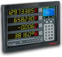
НОВАЯ цифровая индикация DP1200
DP1200 был разработан специально для станков с большим ходом. Он включает в себя функции, необходимые для повышения производительности на расточных станках, VTL, фрезерных станках и токарных станках с большим ходом. DP1200, созданный с учетом потребностей оператора, включает в себя большие четкие цифровые дисплеи и интуитивно понятный цветной экран сообщений TFT, а также дополнительный блок DSU.
(щелкните фото, чтобы увеличить)
Стабильная точность и надежность даже в самых экстремальных производственных условиях Разработанные для работы исключительно с цифровыми считывающими устройствами Newall, энкодеры Spherosyn 2G и Microsyn 2G воплощают поистине новаторский дизайн, в котором вся электроника и измерительные компоненты герметичны и защищены. Энкодеры имеют степень защиты IP67 и будут продолжать обеспечивать точные и надежные показания даже при полном погружении в воду, масло или охлаждающую жидкость. Ни один другой линейный энкодер не сравнится по прочности и надежности со считывающими головками и весами Newall. Стандартная длина хода до 11 метров.

Защита
от окружающей среды Все варианты линейных энкодеров Newall имеют степень защиты от проникновения (IP) 67 (IEC 529). Энкодеры полностью погружны и будут продолжать обеспечивать точные и надежные показания в самых суровых условиях. Грязь, стружка, пыль чугуна, графитовая пыль и другие распространенные загрязнения не повлияют на работу системы линейного энкодера.
Точность, повторяемость и разрешающая способность
Лазерная измерительная система, используемая для калибровки всех весов Newall, была откалибрована аккредитованными лабораториями, обеспечивающими прослеживаемость к национальным стандартам Великобритании. Процедуры соответствуют требованиям британской стандартной спецификации BS5781 / международного стандарта ISO10012-1. Национальная физическая лаборатория (NPL) калибрует эталон, номер сертификата 08A014 / 9501. Все установки Newall Calibration соответствуют этому стандарту NPL. Калибровка весов и считывающих головок Newall проводится при температуре окружающей среды 69,8 ° F (21 ° C).
| Продукт | Точность | Выбираемые разрешения | Повторяемость |
| Сферосин 2Г |
+/- 0,0004 дюйма (10 микрон) |
0,0005 «, 0,0002» | В One Resolution Count |
| Microsyn 2G | +/- 0,0004 дюйма (10 микрон) или +/- 0,0002 (5 микрон) | 0,0005 «, 0,0002» или 0,0005 «, 0,0002, 0,0001, 0,00005″ |
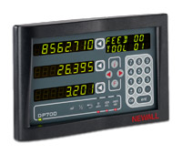
Цифровое считывающее устройство DP700
он DP700 является последним в линии Newall о мощных и интуитивных УЦИ. Устройство заключено в прочный корпус с эргономичным дизайном. УЦИ имеет все основные функции для фрезерных, расточных, токарных, шлифовальных и обычных операций обработки .
Пакет цифрового считывания NMS300
Для станкостроителей и импортеров
Цифровая считывающая система Newall NMS300 устанавливает стандарты надежности, стоимости и простоты использования. Специально разработанная для сотрудничества с производителями и импортерами станков, система УЦИ NMS300 включает энкодеры Newall Spherosyn300 и Microsyn300. Индуктивные энкодеры Newall просты в установке и спроектированы для обеспечения постоянной точности и надежности даже в самых суровых рабочих условиях.
ОСОБЕННОСТИ ВКЛЮЧАЮТ:
- Особые функции токарных и фрезерных станков
- Возможность монтажа на панели
- Возможность выбора разрешения до 1 микрона
- Глобальная техническая поддержка
- Функциональные клавиши, определяемые пользователем
- Доступны специальные монтажные кронштейны
- Доступна индивидуальная маркировка, настройка и отображение сообщения


Преимущество Newall
· Поддержка компании с почти 50-летним проверенным качеством в производстве систем УЦИ и линейных энкодеров
· Надежная и надежная технология индуктивного энкодера
· Датчики имеют степень защиты IP67 — Все электронные и измерительные компоненты изолированы от окружающей среды
· Отсутствие стекла на поломка или царапина
· Постоянно обеспечивает точные показания даже в самых суровых условиях мастерской
· Не требуется чистка или техническое обслуживание
· Устойчивость к ударам и вибрации
· Простота установки — не требуется подкладная планка или обработанная поверхность
ВСЕ ПАКЕТЫ NMS300 ВКЛЮЧАЮТ ВСЕ, НЕОБХОДИМОЕ ДЛЯ
ПОЛНОЙ УСТАНОВКИ: • УЦИ NMS300 (2 или 3 оси)
• Узлы Spherosyn300 и / или Microsyn300 с армированными кабелями
• Комплект кронштейнов шкалы и оборудование
• Кронштейны и крепеж для считывающей головки *
• Монтажный кронштейн и оборудование для дисплея *
* Все пакеты доступны с или без монтажных кронштейнов для считывающей головки и монтажного кронштейна.
Линейные энкодеры Newall DSG и DMG были специально разработаны для использования с конкурирующими брендами дисплеев DRO. Теперь вы можете заменить стеклянные весы на надежные индуктивные энкодеры Newall, устойчивые к охлаждающей жидкости, маслу, грязи и другим условиям окружающей среды.
Конструкция энкодеров DSG и DMG основана на технологии энкодеров Newall Spherosyn и Microsyn, которая имеет экологический рейтинг IP67 и признана во всем мире за качество, точность и надежность.

Энкодер Newall MAG-TS состоит
из считывающей головки, которая перемещается по
магнитно-кодированной ленте. Лента изготовлена из черной основы, прикрепленной к гибкой намагниченной резиновой основе, защищенной защитной полосой из нержавеющей стали.
Угловые показания поворотного стола
Гибкость энкодера MAG-TS позволяет вам крепить ленту по окружности поворотного стола на расточном стане. Угловые значения теперь можно отображать с помощью УЦИ Newall DP1200 или SA-100R .

|
Электрические характеристики |
Механические характеристики |
MAG-TS Монтаж MAG-TS можно установить непосредственно на поверхность станка с помощью прилагаемой клейкой ленты. В качестве альтернативы, ленту можно прикрепить к дополнительному покровителю барукоторый затем крепится к поверхности машины. Считывающая головка должна быть установлена так, чтобы сохранялась правильная высота зазора (0,5 мм +/- 0,02 мм) на протяжении всего хода устройства.
Лента MAG-TS не должна соприкасаться с магнитной стойкой или постоянным магнитом во время установки, использования или обслуживания. Может произойти необратимое повреждение

Абсолютные линейные энкодеры Newall, разработанные для широкого диапазона приложений обратной связи, обеспечивают точное абсолютное положение сразу после включения питания. В кодировщике не используются батареи или статическая память для хранения позиционных данных. Истинное положение может быть восстановлено после подачи питания, независимо от продолжительности или перемещений при отключении питания.
Энкодер идеально подходит для линейных двигателей и других приложений измерения высоких скоростей, включая обратную связь с ЧПУ / ПЛК, машины для захвата и размещения, автомобильные транспортные линии, упаковочные машины, системы на базе ПК и многое другое.

|
Сигнал |
Модель |
Описание |
|---|
|
RS232 |
SHG-A2 |
Последовательная связь RS232 обычно используется для взаимодействия с COM-портами ПК. Этот стандарт EIA позволяет передавать данные от одного передатчика к одному приемнику со скоростью до 20 Кбит / с и на расстоянии до 15 м при максимальной скорости передачи данных. Доступен преобразователь последовательного интерфейса в USB, позволяющий осуществлять интерфейс через |
|
RS485 |
SHG-A4 |
Этот стандарт EIA отвечает требованиям многоточечной сети связи, которая в стандартной комплектации определяет до 32 драйверов и 32 приемников на одной двухпроводной шине. Ключевой особенностью является возможность адресовать отдельные устройства. Эту модель можно заказать с уникальными адресными метками, чтобы облегчить подключение нескольких устройств к шине RS485 . SHG-A4 — протокол RS485 ( 241k ) |
|
SSI |
|
SSI (синхронный последовательный интерфейс) — это запатентованный протокол абсолютного кодировщика. |
|
SHG-AB |
SSI Binary | Биты данных: 24 | Четность: Нет |
|
|
SHG-AG |
Код Серого SSI | Биты данных: 24 | Четность: Нет |
|
|
SHG-AS |
Код Грея SSI с инкрементными сигналами TTL (обычно используется для управления Siemens) Биты данных: 24 | Четность: четная. SHG-AS — SSI с протоколом четности Quad ( 226k ) |
|
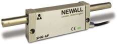
| Fanuc Последовательный | SHG-AF | Это собственный протокол абсолютного кодировщика. Он используется исключительно с продуктами Fanuc с ЧПУ, которые требуют абсолютной обратной связи по положению. SHG-AF — Протокол Fanuc ( 305k ) |
Последовательная связь RS232 обычно используется для взаимодействия с COM-портами ПК. Доступен преобразователь последовательного интерфейса в USB, позволяющий осуществлять интерфейс через порт USB. Абсолютный датчик линейных перемещений SHG-A2, разработанный для широкого диапазона приложений обратной связи, обеспечивает точное абсолютное положение сразу после включения питания. В кодировщике не используются батареи или статическая память для хранения позиционных данных. Истинное положение может быть восстановлено после подачи питания, независимо от продолжительности или перемещений при отключении питания.
| Выходной сигнал | RS232 |
|---|---|
|
Точность / метр |
± 0,0004 «, ± 0,0002», ± 0,0001 «(± 10 мкм, ± 5 мкм, ± 3 мкм) |
|
Резолюции |
10 мкм, 5 мкм, 1 мкм или 0,5 мкм |
|
Масштабные путешествия |
От 4 до 137,8 дюйма (от 102 до 3,5 м) |
|
Диаметр шкалы |
0,601 дюйма (15,25 мм) |
|
Размеры считывающей головки |
2,05 дюйма (В) x 5,16 дюйма (Д) x 1,10 дюйма (Г) (52 мм x 131 мм x 28 мм) |
|
Контрольный маркер |
н / д |
|
Максимальная скорость перемещения |
н / д |
|
Источник питания |
5 В постоянного тока ± 5%, <350 мА |
|
Шок (11 мс) |
100 г (IEC 69-2-6) |
|
Вибрация (55-2000 Гц) |
30 г (IEC 68-2-27) |
|
Период выборки |
50 мкс |
|
Экологический рейтинг |
IP67, полностью погружаемый (IEC 529) — превосходит NEMA 6 |
|
Рабочая Температура |
От 32 до 131 ° F (от 0 до 55 ° C) |
|
Коэффициент расширения |
12 х 10-6 К |
|
Материал шкалы |
Нержавеющая сталь 316 |
|
Общая длина шкалы |
Длина хода шкалы + 10,2 дюйма (258 мм) |
|
Стандартный кабель |
15-жильный, 11,5 ‘(3,5 м) бронированный |
|
Максимальная длина кабеля |
65,6 ‘(20 м) |
|
Стандартный разъем |
15-контактный тип «D» |
|
Соответствие нормам электромагнитной совместимости |
BS EN 61000-6-2 и BS EN 61000-6-4 |
|
Параметры |
|---|
|
Резолюции |
Доступны специальные разрешения |
|---|---|
|
Небронированный кабель |
PUR (полиуретан) |
|
Разъемы |
• IP67 (NEMA 6) |
|
Длина кабеля |
22 фута (7 м) или 19,68 дюйма (0,5 м) |
Быстрая и простая установка
Конструкция этих линейных энкодеров позволяет устанавливать их практически в любом положении, в отличие от линейных энкодеров со стеклянной шкалой, которые обычно необходимо устанавливать так, чтобы манжетное уплотнение было обращено вниз, чтобы предотвратить загрязнение. Самоцентрирующиеся фиксирующие кронштейны позволяют практически без усилий установить весы, для чего требуется только одно отверстие для каждого набора кронштейнов.
Линейный энкодер SHG-A4

RS485 отвечает требованиям многоточечной сети связи, которая может иметь до 32 драйверов и 32 приемников на одной двухпроводной шине. Ключевой особенностью является возможность адресовать отдельные устройства. Эту модель можно заказать с уникальными адресными бирками. Абсолютный датчик линейных перемещений SHG-A4, разработанный для широкого спектра приложений обратной связи, обеспечивает определение истинного абсолютного положения сразу после включения питания. В кодировщике не используются батареи или статическая память для хранения позиционных данных. Истинное положение может быть восстановлено после подачи питания, независимо от продолжительности или перемещений при отключении питания.
SSI (Synchronous Serial Interface) is a patented absolute encoder protocol invented by Max Stegmann GmbH. The transfer of position data is much faster than RS232 or RS485, making this protocol ideal for closed loop motion control. There are several variations of SSI currently available. Developed to meet a wide range of feedback applications, these absolute linear encoders provide a true absolute position immediately upon power-up. The encoder does not use batteries or static memory to retain the positional data. True position can be reacquired once power is applied, regardless of duration or power-off movements.

RS485 отвечает требованиям многоточечной сети связи, которая может иметь до 32 драйверов и 32 приемников на одной двухпроводной шине. Ключевой особенностью является возможность адресовать отдельные устройства. Эту модель можно заказать с уникальными адресными бирками. Абсолютный датчик линейных перемещений SHG-A4, разработанный для широкого спектра приложений обратной связи, обеспечивает определение истинного абсолютного положения сразу после включения питания. В кодировщике не используются батареи или статическая память для хранения позиционных данных. Истинное положение может быть восстановлено после подачи питания, независимо от продолжительности или перемещений при отключении питания
SHG-AF Linear Encoder
This protocol is proprietary to Fanuc and available on all of their control systems. The controller makes a request for positional data and the encoder has to respond correctly with data within a strictly controlled time state. Developed to meet a wide range of feedback applications, the
SHG-AF absolute linear encoder provides a true absolute position immediately upon power-up. The encoder does not use batteries or static memory to retain the positional data. True position can be reacquired once power is applied, regardless of duration or power-off movements.
Линейный кодировщик MCG-TT
Линейный энкодер MCG-TT обеспечивает сверхнизкий профиль энкодера для ограниченного пространства без необходимости жертвовать производительностью или устойчивостью к окружающей среде. Считывающая головка MCG цилиндрической формы может быть помещена в отверстие диаметром всего 16 мм, что дает широкий спектр возможностей применения. Кодер выдает сигнал TTL-RS422 Дифференциальной квадратуры с периодической контрольной отметкой.
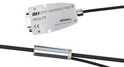
| Выходной сигнал | TTL RS422 Дифференциальная квадратура |
| Тип ссылки | Периодический — каждые 5 мм |
| Шкала OD | 5,75 мм (0,2 дюйма) |
| Размер читающей головки | 56,2 мм x 16,0 мм / внешний диаметр (2,21 дюйма x 0,63 дюйма / внешний диаметр) |
| Максимальный масштабный ход | 1000 мм (39 дюймов) |
MHG-TT совместим с большинством систем управления ПЛК и ЧПУ. Энкодер обеспечивает выход дифференциального квадратурного сигнала с уровнями TTL. Периодическая референтная метка обычно используется для самонаведения.

MHG-VP предназначен для использования вместе с модулем Newall SCC-200. SCC-200 будет выдавать синусоидальный / косинусный сигнал ~ 1Vpp, что делает его идеально подходящим для ЧПУ и другой обратной связи управления.
SHG-PV обеспечивает дифференциальный квадратурный выходной сигнал с уровнями 5–28 В. Квадратурный выход эквивалентен входному постоянному напряжению. SHG-PV принимает входное напряжение 5–28 В постоянного тока.
Примеры:
- Если на энкодер подается напряжение 5 В постоянного тока, на выходе будет квадратурное напряжение 5 В.
- Если на энкодер подается напряжение 24 В постоянного тока, на выходе будет квадратурное напряжение 24 В.

SPB-TT and SPB-TS Linear Press Brake Encoders
SHG-VS линейного кодера предназначен для использования с модулем SCC-200. SCC-200 будет выдавать синусоидальный / косинусный сигнал ~ 1Vpp с одним опорным маркером. Энкодер имеет четыре выбираемых референтных маркера, расположенных через каждые 25,4 мм. Ссылка, выбранная для выходной ссылки, зависит от углового выравнивания шкалы относительно считывающей головки при установке.
Программируемый поворотный энкодер RPE-PV
RPE-PV от Newall обладает возможностью динамического разрешения энкодера, что позволяет пользователям легко программировать разрешение энкодера на любое значение от 1 до 10 000 отсчетов на оборот.
Пользователи могут программировать и перепрограммировать разрешение кодировщика на месте по мере необходимости. Используя дополнительный кабель для программирования, подключите кодировщик к компьютеру через порт USB. Просто введите новое разрешение и нажмите «Программа». Теперь запрограммировано новое разрешение. Это так просто.
Преимущества:
- Просто программировать
- Устанавливается как стандартный кодировщик
- Мгновенная положительная индикация запрограммированного значения
- Исключите догадки о разрешении кодировщика
- Высокая скорость работы из-за большого количества оснований
- Широкий диапазон возможных отсчетов за оборот CPR — от 1 до 10 000
- Автоматическое позиционирование индексного импульса
- Легко изменить CPR для ситуаций прототипирования и настройки машины
- Уменьшите запас различных кодировщиков CRP для обслуживания (держите на складе только один тип и программируйте его по мере необходимости)


SPB-TT and SPB-TS Linear Press Brake Encoders
• Допуск до ± 3 мм на радиальное перемещение из-за отклонения листогибочного пресса
• Индуктивная система без оптики, которая могла бы выйти из строя или стать загрязненной
• Доступна с одиночным или периодическим эталонным маркером
• Запатентованный механизм самоустанавливающегося монтажа
• Дифференциальный квадратурный выход RS422
• Простая установка; Отсутствие движущихся частей
• Полная герметичность, степень защиты IP67
• Устойчивость к ударам и вибрации
|
Характеристики |
|---|
|
Выходной сигнал |
~ 1Vpp от преобразователя SCC-200 |
|---|---|
|
Точность / метр |
± 0,0004 «(± 10 мкм) |
|
Разрешение от SCC-200 |
Период сигнала 20 мкм |
|
Масштабные путешествия |
От 2 дюймов до 462 дюймов (от 51 мм до 11,73 м) |
|
Диаметр шкалы |
0,601 дюйма (15,25 мм) |
|
Размеры считывающей головки |
2,05 дюйма (В) x 5,16 дюйма (Д) x 1,10 дюйма (Г) (52 мм x 131 мм x 28 мм) |
|
Контрольный маркер |
Одиночный (выберите 1 из 4) |
|
Источник питания |
5 В постоянного тока ± 5%, <300 мА (с SCC-200) |
|
Шок (11 мс) |
100 г (IEC 69-2-6) |
|
Вибрация (55-2000 Гц) |
30 г (IEC 68-2-27) |
|
Период выборки |
100 мкс |
|
Экологический рейтинг |
IP67, полностью погружаемый (IEC 529) — превосходит NEMA 6 |
|
Рабочая Температура |
От 32 до 131 ° F (от 0 до 55 ° C) |
|
Коэффициент расширения |
12 х 10-6 К |
|
Материал шкалы |
Нержавеющая сталь 316 |
|
Общая длина шкалы |
Длина хода шкалы + 10,2 дюйма (258 мм) |
|
Стандартный кабель |
9-жильный, 11,5 ‘(3,5 м) бронированный |
|
Максимальная длина кабеля |
82 ‘(25 м) |
|
Стандартный разъем |
9-контактный тип «D» |
|
Соответствие нормам электромагнитной совместимости |
BS EN 50081-2 и BS EN 61000-6-2 |
|
Параметры |
|---|
|
Резолюции |
Доступны специальные разрешения |
|---|---|
|
Небронированный кабель |
PUR (полиуретан) |
|
Разъемы |
• Honda PCR-E20FS (Fanuc) |
|
Длина кабеля |
22 фута (7 м) или 19,68 дюйма (0,5 м |
| Характеристики | |
| Класс точности | ± 10 мкм (± 0,0004 дюйма) |
| Полная длина | Ход + 277,5 мм (10,93 дюйма) |
| Диапазон температур хранения | От -20 до 70ºC (от -4 до 158ºF) |
| Диапазон рабочих температур | От 0 до 55ºC (от 32 до 131ºF) |
| Соответствие нормам электромагнитной совместимости | BS EN 50081-2 и BS EN 50082-2 |
| Движущая сила | <5N |
| Уровень защиты от проникновения | IP67, полностью погружаемый (IEC 529) — превосходит NEMA 6 |
| Вибрация (55-2000 Гц) | 30 г / 294 м / с2 (IEC 68-2-27) |
| Шок (11 мс) | 100 г / 980 м / с2 (IEC 69-2-6) |
| Ссылка | SPB-TS = 4, каждые 50,8 мм от конца шкалы SPB-TT = Периодически каждые 12,7 мм по ходу |
| Источник питания | 5 В постоянного тока ± 5% <85 мА |
| Максимальный акк. / Декабрь. | 10 г / 100 м / с |
| Максимальная скорость перемещения | 1 м / с |
| Тип выхода | RS422 Дифференциальная квадратура |
| Разрешение (мкм / м) | 1 мкм, 5 мкм или 10 мкм |
| Допуск соосности при установке | ± 3 мм (нажатие закрыто) |
Newall предлагает заменители линейных энкодеров Plug and Play для фрезерных станков с ЧПУ с элементами управления ProtoTrak
Newall Electronics теперь предлагает прямую замену линейных энкодеров для датчиков Trak или стеклянных весов на заводах с элементами управления ProtoTrak. Линейные энкодеры SHG отличаются известной надежностью, не требующей обслуживания, и известны линейные энкодеры Newall Spherosyn и Microsyn. Нет более дорогостоящего ремонта датчика колеса или утомительной очистки стекла от накипи. Энкодеры Newall для элементов управления ProtoTrak подключаются напрямую и не требуют специальных параметров управления для настройки или изменения. Воспользуйтесь всеми преимуществами точности линейного энкодера без потери времени из-за сбоя энкодера.

Запчасти для цифровых считывающих систем Newall
Newall предлагает непревзойденную поддержку и гарантии для наших цифровых считывающих систем. Обратитесь за помощью к нашему опытному персоналу службы технической поддержки. Мы поможем вам получить запасные части в три простых шага.
1. Определите детали, которые необходимо заменить.
2. Проверьте статус гарантии.
3. Отправьте запасные части.
Запчасти для цифровых считывающих систем конкурентов
Линейные энкодеры Newall DSG и DMG были специально разработаны для использования с конкурирующими брендами цифровых дисплеев. Теперь вы можете заменить стеклянные весы на надежные индуктивные энкодеры Newall, устойчивые к охлаждающей жидкости, маслу, грязи и другим условиям окружающей среды.
![]()
Newall является мировым специалистом высококачественных и высокопроизводительных цифровых систем считывания (DRO) и линейных датчиков обратной связи, обеспечивая надежное, точные и продукты для широкого спектра измерительных приложений по всему миру. уникальная технология индуктивного датчика Newall обеспечивает бескомпромиссную точность в пределах самых жестких и самых экстремальных условиях окружающей среды, в частности, в приложениях станков. Newall поддерживает свои продукты с глобальной командой, которая стремится обеспечить своим клиентам самый высокий уровень технической поддержки и обслуживания клиентов.
Системы Newall Цифровые датчики (ДРО) предлагают исключительную ценность с передовых технологий и повышению производительные функции. .jpg) Предназначен для использования с Spherosyn ™ и Microsyn ™ линейных датчиков, цифровые системы считывания по Newall хорошо известны для обеспечения наилучших решений для любого применения машины.Прочный литой корпус и чистые фасадные панели, Newall ДРО Системы долговечны.
Предназначен для использования с Spherosyn ™ и Microsyn ™ линейных датчиков, цифровые системы считывания по Newall хорошо известны для обеспечения наилучших решений для любого применения машины.Прочный литой корпус и чистые фасадные панели, Newall ДРО Системы долговечны.
Поставляемая продукция
- DP1200 Digital Readout
- DP500 турель Mill и инструментальный токарный станок ДРО Пакеты
- DP700 Digital Readout
- Датчик BCS M12BBG1-PSC80H-2
-
Датчик SHG ТТ 01009D0101016
1 ООО mm Newall
Download Operation & user’s manual of Newall dp1200 Other for Free or View it Online on All-Guides.com.

1

2

3

4

5

6

7

8

9

10

11

12

13

14

15

16

17

18

19

20

21

22

23

24

25

26

27

28

29

30

31

32

33

34

35

36

37

38

39

40

41

42

43

44

45

46

47

48

49

50

51

User Manual
DP1200 Digital Readout
Standard Functions
RS232 Setup (Continued)
If off is selected
If Enter Key or Periodic are selected
Note: Period will only be shown if the Periodic output was selected
33
To turn Data Logging off
To use Enter Key to trigger Data Logging
To select Data Logging periodically
to return to the main menu and disable Data Logging
Select the Baud Rate to match the
baud rate supported at the PC
To select None (disable Parity)
To select Even Parity
To selects Odd Parity
Enter, using the numeric keypad, the
number of seconds between each
communication
The RS232 is now live and functioning
|
Detail Specifications: 1313/1313624-dp1200.pdf file (03 Mar 2023) |
Accompanying Data:
Newall dp1200 Other PDF Operation & User’s Manual (Updated: Friday 3rd of March 2023 06:31:34 AM)
Rating: 4.1 (rated by 2 users)
Compatible devices: NMS 300, HIGHLOW CONDUCTIVITY TESTER, LATINA, DP700, 590t Treadmill, CXW-219-D69, LS-HM1-D, ELPI5SJ10.
Recommended Documentation:
Text Version of Operation & User’s Manual
(Ocr-Read Summary of Contents, UPD: 03 March 2023)
-
33, Newall dp1200 RS232 (Data Logging) / Data Acquisition 32 Standard Functions The DP1200 can offer basic serial communication via a dedicated RS232 compatible port, which is used for data logging purposes. RS232 Connections The RS232 is connected to the DP1200 via a 15-pin D-type connector at the rear of the display. The required connection details are shown below. The RS232 port allows position da…
-
11, 10 Setting Up The Unit Setup Menu Navigation (continued) Navigating Axis 4 Setup (Digital Rotary Linear) Quick Navigation of Axis 4 Setup (Digital Rotary Linear) Numeric Key Setup Function 1 Legend Setup 2 Encoder Setup 3 Reference Source Setup 4 Resolution Setup 7 Display Resolution Setup 8 Direction Setup 9 More Options Press Key 9 for the options below …
-
36, Newall dp1200 PCD / Bolt Hole Circle 35 Mill Functions The DP1200 calculates positions for a series of equally spaced holes around the circumference of a circle. Once the parameter data is entered, the DP1200 displays the distance to the next hole. The operator works to zero for each hole location. See example (Fig 1). Note: This function only operates in the axes that have been setup in the plane (See Pa…
-
17, Setting Up The Unit 16 Segmented Error Compensation The scale travel is broken down into as many as 200 user-defined segments, each with their own c orrection factor, measured against a high-accuracy standard. The following parameters need to be identified; Each Correction Point is measured with respect to the Starting Point — zero — which is usually set close to one end of the scale…
-
14, Default is 0.000 Setting Up The Unit Zero Approach Setup 13 Navigate to This setting provides a visual indication that one or more axes are approaching zero. This is done by using the far left LED segment on each axis, as the axis approaches zero, each segment of the ‘0’ lights up in quick succession. Once zero has been reached, the ‘0’ to the far left wil…
-
23, Legend Setup 22 Encoder Resolution Setup Setting Up The Unit Please refer to Page 10, Legend Setup Encoder Setup To select Rotary (Linear) as the encoder type To select Program Resolution To select Teach Resolution Program Resolution Setup Teach Resolution Setup Reference Source Setup Please refer to Page 16, Reference Source Setup Enter the linear resolution via the numeric keypad. Example: 1…
-
27, Setting Up The Unit Sleep Setup 26 Allows the user to select a time period where the unit will automatically go into Sleep Mode. If no move- ment is made or keys pressed for the time period set, the sleep mode will be activated. Example: The sleep time is required after 5 minutes Unlock Axis Allows the unit to be upgraded from a 2 or 3 Axis uni…
-
16, Newall dp1200 15 Setting Up The Unit Error Compensation Setup Navigate to To select no Compensation (None) To select Linear Error Compensation To select Segmented Error Compensation Linear Error Compensation Setup To select Teach mode To select Program mode Teach Mode 0.000 499.875 500.000 Program Mode First determine the correction factor required. To do this, use the following equat…
-
29, 28 Standard Functions Zero and Preset an Axis The DP1200 has a dedicated key to switch the operation of the axis selection key between Zero Mode and Set Mode. The selected mode is indicated by an LED either above or below the key as shown on the right. Press to toggle between ‘Set’ and ‘Zero’ Mode Zero mode has been selected Set mode has bee…
-
20, Setting Up The Unit Error Compensation Setup 19 Signal Checking Setup The DP1200 has the facility to detect if the encoder attached to the 4th digital axis has become disconnected, sustained severe cable damage, or with some encoders, experienced electronic failure. To enable Signal Checking To disable Signal Checking Zero Approach Setup Please refer to Page 11, Zero Approach Setup…
-
43, Mill Functions Skew 42 The Skew Feature provides capability for the DRO to find the skew angle of a part. It is very useful for the machine operator to know if the part is square to the bed. It can also be used to find other angles on the workpiece. The plane setting parameter defines which axes are used for this feature. To select the Skew function. Note: Use the keys to navigate through the …
Recommended Instructions:
eTrex Summit — Hiking GPS Receiver, TI070, E1250TW, HSU-09LEB13-H — annexe 1


-
MODEL 742 SPEAKER SYSTEM SPECS:Frequency Response: 65 Hz to 17 kHz ±3 dBUseable Low Frequency: 42 Hz (-10 dB)Power Handling: 400w Continuous PowerRecommended Amp: 5 to 600 wattsSensitivity: 101 dB SPL, 1 Watt @ 1 meterCoverage Angles: 90° Horizontal, 45° VerticalImp: 8ΩHorn Driver Protection: YesInputs/Outputs: Two 1/4″ Woofer Enclosure Type: Closed BoxEnclosure Cove …
742-742P-V1 2
-
PhilipsHybridShellFor iPodnano G4DLA71028Protect your iPod in a clear shellwith non-slip silicone backTough and transparent, HybridShell is a fusion of crystal-clear polycarbonate with a non-slip rubberised back. This combination provides strong protection plus grip in one unique case. The case also features built-in screen protection.Strong protection• Crystal clea …
DLA71028 2
-
Quality since 19469049 Tyler Blvd. • Mentor, Ohio 44060Phone (440) 974-8888 • Fax (440) 974-0165Toll-Free Fax 800-841-8003 • buyersproducts.comInstallation InstructionsAS301 Air Shift CylinderThe AS301 Air Shift Cylinder mounts to Buyers BPC1010-Series, Permco 640-Series, or Commercial C101-Series Dump Pump/Valve in place of the detent assembly.4. Remove four cap screws and slide end …
AS301 2
-
DIGITAL VOICE RECORDER MODEL:ICR-110 BEFORE OPERATING THIS PRODUCT, PLEASE READ THESE INSTRUCTIONS COMPLETELY. I CE “Read all instruction before use” and save for future reference PRECAUTIONS To maintain optimum performance: Do not use unit in places which are extremely hot, cold, dusty or humid. …
ICR 110 4