- @subpage Introduction
- @subpage The-Core-Objects
- @subpage Resource-Management
- @subpage Scripts
- @subpage rtss
- @subpage Mesh-Tools
- @subpage Hardware-Buffers
- @subpage Shadows
- @subpage Animation
- @subpage Instancing
- @subpage Cross-platform-Shaders
@page Introduction Introduction
This chapter is intended to give you an overview of the main components of OGRE and why they have been put together that way.
Object Orientation — more than just a buzzword
The name is a dead giveaway. It says Object-Oriented Graphics Rendering Engine, and that’s exactly what it is. Ok, but why? Why did I choose to make such a big deal about this?
Well, nowadays graphics engines are like any other large software system. They start small, but soon they balloon into monstrously complex beasts which just can’t be all understood at once. It’s pretty hard to manage systems of this size, and even harder to make changes to them reliably, and that’s pretty important in a field where new techniques and approaches seem to appear every other week. Designing systems around huge files full of C function calls just doesn’t cut it anymore — even if the whole thing is written by one person (not likely) they will find it hard to locate that elusive bit of code after a few months and even harder to work out how it all fits together.
Object orientation is a very popular approach to addressing the complexity problem. It’s a step up from decomposing your code into separate functions, it groups function and state data together in classes which are designed to represent real concepts. It allows you to hide complexity inside easily recognised packages with a conceptually simple interface so they are easy to recognise and have a feel of ’building blocks’ which you can plug together again later. You can also organise these blocks so that some of them look the same on the outside, but have very different ways of achieving their objectives on the inside, again reducing the complexity for the developers because they only have to learn one interface.
I’m not going to teach you OO here, that’s a subject for many other books, but suffice to say I’d seen enough benefits of OO in business systems that I was surprised most graphics code seemed to be written in C function style. I was interested to see whether I could apply my design experience in other types of software to an area which has long held a place in my heart — 3D graphics engines. Some people I spoke to were of the opinion that using full C++ wouldn’t be fast enough for a real-time graphics engine, but others (including me) were of the opinion that, with care, and object-oriented framework can be performant. We were right.
In summary, here’s the benefits an object-oriented approach brings to OGRE:
@par Abstraction
Common interfaces hide the nuances between different implementations of 3D API and operating systems
@par Encapsulation
There is a lot of state management and context-specific actions to be done in a graphics engine — encapsulation allows me to put the code and data nearest to where it is used which makes the code cleaner and easier to understand, and more reliable because duplication is avoided
@par Polymorphism
The behaviour of methods changes depending on the type of object you are using, even if you only learn one interface, e.g. a class specialised for managing indoor levels behaves completely differently from the standard scene manager, but looks identical to other classes in the system and has the same methods called on it
Multi-everything
OGRE is more than a 3D engine that runs on one 3D API, on one platform, with one type of scene (indoor levels are most popular). OGRE is able to extend to any kind of scene (but yet still implements scene-specific optimisations under the surface), any platform and any 3D API.
Therefore all the ’visible’ parts of OGRE are completely independent of platform, 3D API and scene type. There are no dependencies on Windows types, no assumptions about the type of scene you are creating, and the principles of the 3D aspects are based on core maths texts rather than one particular API implementation.
Now of course somewhere OGRE has to get down to the nitty-gritty of the specifics of the platform, API and scene, but it does this in subclasses specially designed for the environment in question, but which still expose the same interface as the abstract versions.
For example, there is a @c Win32Window class which handles all the details about rendering windows on a Win32 platform — however the application designer only has to manipulate it via the superclass interface Ogre::RenderWindow, which will be the same across all platforms.
Similarly the Ogre::SceneManager class looks after the arrangement of objects in the scene and their rendering sequence. Applications only have to use this interface, but there is a Ogre::OctreeSceneManager class which optimises the scene management for outdoor levels, meaning you get both performance and an easy to learn interface. All applications have to do is hint about the kind of scene they will be creating and let OGRE choose the most appropriate implementation — this is covered in a later tutorial.
OGRE’s object-oriented nature makes all this possible. Currently OGRE runs on different platforms using plugins to drive the underlying rendering API. Applications use OGRE at the abstract level, thus ensuring that they automatically operate on all platforms and rendering subsystems that OGRE provides without any need for platform or API specific code.
@page The-Core-Objects The Core Objects
@tableofcontents
This tutorial gives you a quick summary of the core objects that you will use in OGRE and what they are used for.
Overview from 10,000 feet
Shown below is a diagram of some of the core objects and where they ’sit’ in the grand scheme of things. This is not all the classes by a long shot, just a few examples of the more more significant ones to give you an idea of how it slots together.
At the very top of the diagram is the Root object. This is your ’way in’ to the OGRE system, and it’s where you tend to create the top-level objects that you need to deal with, like scene managers, rendering systems and render windows, loading plugins, all the fundamental stuff. If you don’t know where to start, Root is it for almost everything, although often it will just give you another object which will actually do the detail work, since Root itself is more of an organiser and facilitator object.
The majority of rest of OGRE’s classes fall into one of 3 roles:
@par Scene Management
This is about the contents of your scene, how it’s structured, how it’s viewed from cameras, etc. Objects in this area are responsible for giving you a natural declarative interface to the world you’re building; i.e. you don’t tell OGRE «set these render states and then render 3 polygons», you tell it «I want an object here, here and here, with these materials on them, rendered from this view», and let it get on with it.
@par Resource Management
All rendering needs resources, whether it’s geometry, textures, fonts, whatever. It’s important to manage the loading, re-use and unloading of these things carefully, so that’s what classes in this area do.
@par Rendering
Finally, there’s getting the visuals on the screen — this is about the lower-level end of the rendering pipeline, the specific rendering system API objects like buffers, render states and the like and pushing it all down the pipeline. Classes in the Scene Management subsystem use this to get their higher-level scene information onto the screen.

You’ll notice that scattered around the edge are a number of plugins. OGRE is designed to be extended, and plugins are the usual way to go about it. Many of the classes in OGRE can be subclassed and extended, whether it’s changing the scene organisation through a custom SceneManager, adding a new render system implementation (e.g. Direct3D or OpenGL), or providing a way to load resources from another source (say from a web location or a database). Again this is just a small smattering of the kinds of things plugins can do, but as you can see they can plug in to almost any aspect of the system. This way, OGRE isn’t just a solution for one narrowly defined problem, it can extend to pretty much anything you need it to do.
The Root object {#The-Root-Object}
The Ogre::Root object is the entry point to the OGRE system. This object MUST be the first one to be created, and the last one to be destroyed. In the example applications I chose to make an instance of Root a member of my application object which ensured that it was created as soon as my application object was, and deleted when the application object was deleted.
The root object lets you configure the system, for example through the Ogre::Root::showConfigDialog method which is an extremely handy method which performs all render system options detection and shows a dialog for the user to customise resolution, colour depth, full screen options etc. It also sets the options the user selects so that you can initialise the system directly afterwards.
The root object is also your method for obtaining pointers to other objects in the system, such as the Ogre::SceneManager, Ogre::RenderSystem and various other resource managers. See below for details.
Finally, if you run OGRE in continuous rendering mode, i.e. you want to always refresh all the rendering targets as fast as possible (the norm for games and demos, but not for windowed utilities), the root object has a method called Ogre::Root::startRendering, which when called will enter a continuous rendering loop which will only end when all rendering windows are closed, or any Ogre::FrameListener objects indicate that they want to stop the cycle (see below for details of Ogre::FrameListener objects).
The RenderSystem object {#The-RenderSystem-object}
The Ogre::RenderSystem object is actually an abstract class which defines the interface to the underlying 3D API. It is responsible for sending rendering operations to the API and setting all the various rendering options. This class is abstract because all the implementation is rendering API specific — there are API-specific subclasses for each rendering API (e.g. D3DRenderSystem for Direct3D). After the system has been initialised through Ogre::Root::initialise, the Ogre::RenderSystem object for the selected rendering API is available via the Ogre::Root::getRenderSystem() method.
However, a typical application should not normally need to manipulate the Ogre::RenderSystem object directly — everything you need for rendering objects and customising settings should be available on the Ogre::SceneManager, Material and other scene-oriented classes. It’s only if you want to create multiple rendering windows (completely separate windows in this case, not multiple viewports like a split-screen effect which is done via the RenderWindow class) or access other advanced features that you need access to the RenderSystem object.
For this reason I will not discuss the Ogre::RenderSystem object further in these tutorials. You can assume the Ogre::SceneManager handles the calls to the Ogre::RenderSystem at the appropriate times.
The SceneManager object {#The-SceneManager-object}
Apart from the Ogre::Root object, this is probably the most critical part of the system from the application’s point of view. Certainly it will be the object which is most used by the application. The Ogre::SceneManager is in charge of the contents of the scene which is to be rendered by the engine. It is responsible for organising the contents using whatever technique it deems best, for creating and managing all the cameras, movable objects (entities), lights and materials (surface properties of objects), and for managing the ’world geometry’ which is the sprawling static geometry usually used to represent the immovable parts of a scene.
It is to the SceneManager that you go when you want to create a camera for the scene. It’s also where you go to retrieve or to remove a light from the scene. There is no need for your application to keep lists of objects, the SceneManager keeps a named set of all of the scene objects for you to access, should you need them. Look in the main documentation under the getCamera, getLight, getEntity etc methods.
The SceneManager also sends the scene to the RenderSystem object when it is time to render the scene. You never have to call the Ogre::SceneManager::_renderScene method directly though — it is called automatically whenever a rendering target is asked to update (see Ogre::Root::renderOneFrame for details).
So most of your interaction with the SceneManager is during scene setup. You’re likely to call a great number of methods (perhaps driven by some input file containing the scene data) in order to set up your scene. You can also modify the contents of the scene dynamically during the rendering cycle if you create your own FrameListener object (see later).
Because different scene types require very different algorithmic approaches to deciding which objects get sent to the RenderSystem in order to attain good rendering performance, the SceneManager class is designed to be subclassed for different scene types. The default SceneManager object will render a scene, but it does little or no scene organisation and you should not expect the results to be high performance in the case of large scenes. The intention is that specialisations will be created for each type of scene such that under the surface the subclass will optimise the scene organisation for best performance given assumptions which can be made for that scene type. An example is the @c OctreeSceneManager which optimises rendering for large levels based on the Octree partitioning scheme.
You can specify the SceneManager type you want as the parameter of Ogre::Root::createSceneManager. If you do not specify any parameter, OGRE will use to the default SceneManager, which is well suited for small and moderate sized scenes.
The ResourceGroupManager Object {#The-ResourceGroupManager-Object}
The Ogre::ResourceGroupManager class is actually a ’hub’ for loading of reusable resources like textures and meshes. It is the place that you define groups for your resources, so they may be unloaded and reloaded when you want. Servicing it are a number of ResourceManagers which manage the individual types of resource, like Ogre::TextureManager or Ogre::MeshManager. In this context, resources are sets of data which must be loaded from somewhere to provide OGRE with the data it needs.
ResourceManagers ensure that resources are only loaded once and shared throughout the OGRE engine. They also manage the memory requirements of the resources they look after. They can also search in a number of locations for the resources they need, including multiple search paths and compressed archives (ZIP files).
Most of the time you won’t interact with resource managers directly. Resource managers will be called by other parts of the OGRE system as required, for example when you request for a texture to be added to a Material, the Ogre::TextureManager will be called for you. If you like, you can call the appropriate resource manager directly to preload resources (if for example you want to prevent disk access later on) but most of the time it’s ok to let OGRE decide when to do it.
One thing you will want to do is to tell the resource managers where to look for resources. You do this via Ogre::ResourceGroupManager::addResourceLocation.
As its name already tells, the ResourceGroupManager keeps resources organized in Groups. These define a set of Resources that shall be loaded / unloaded as a unit. For example, it might be all the resources used for the level of a game.
By default the «General» group is used, which will only be unloaded on shutdown. To define your own groups use Ogre::ResourceGroupManager::createResourceGroup.
Because there is only ever 1 instance of each resource manager in the engine, if you do want to get a reference to a resource manager use the following syntax:
Ogre::TextureManager::getSingleton().someMethod()
Ogre::MeshManager::getSingleton().someMethod()
The Mesh Object {#The-Mesh-Object}
A Ogre::Mesh object represents a discrete model, a set of geometry which is self-contained and is typically fairly small on a world scale. Ogre::Mesh objects are assumed to represent movable objects and are not used for the sprawling level geometry typically used to create backgrounds.
Ogre::Mesh objects are a type of resource, and are managed by the MeshManager resource manager. They are typically loaded from OGRE’s custom object format, the ’.mesh’ format. Mesh files are typically created by exporting from a modelling tool See [Exporters](@ref Exporters) and can be manipulated through various [Mesh Tools](@ref Mesh-Tools)
You can also create Mesh objects manually by calling the Ogre::MeshManager::createManual method. This way you can define the geometry yourself, but this is outside the scope of this manual.
Mesh objects are the basis for the individual movable objects in the world, which are called @ref Entities.
Mesh objects can also be animated using See @ref Skeletal-Animation.
Entities {#Entities}
An entity is an instance of a movable object in the scene. It could be a car, a person, a dog, a shuriken, whatever. The only assumption is that it does not necessarily have a fixed position in the world.
Entities are based on discrete meshes, i.e. collections of geometry which are self-contained and typically fairly small on a world scale, which are represented by the Ogre::Mesh object. Multiple entities can be based on the same mesh, since often you want to create multiple copies of the same type of object in a scene.
You create an entity by calling the Ogre::SceneManager::createEntity method, giving it a name and specifying the name of the mesh object which it will be based on (e.g. ’muscleboundhero.mesh’). The Ogre::SceneManager will ensure that the mesh is loaded by calling the Ogre::MeshManager resource manager for you. Only one copy of the Mesh will be loaded.
Ogre::Entities are not deemed to be a part of the scene until you attach them to a Ogre::SceneNode (see the section below). By attaching entities to SceneNodes, you can create complex hierarchical relationships between the positions and orientations of entities. You then modify the positions of the nodes to indirectly affect the entity positions.
When a Ogre::Mesh is loaded, it automatically comes with a number of materials defined. It is possible to have more than one material attached to a mesh — different parts of the mesh may use different materials. Any entity created from the mesh will automatically use the default materials. However, you can change this on a per-entity basis if you like so you can create a number of entities based on the same mesh but with different textures etc.
To understand how this works, you have to know that all Mesh objects are actually composed of Ogre::SubMesh objects, each of which represents a part of the mesh using one Material. If a Ogre::Mesh uses only one Ogre::Material, it will only have one Ogre::SubMesh.
When an Ogre::Entity is created based on this Mesh, it is composed of (possibly) multiple Ogre::SubEntity objects, each matching 1 for 1 with the Ogre::SubMesh objects from the original Mesh. You can access the Ogre::SubEntity objects using the Ogre::Entity::getSubEntity method. Once you have a reference to a Ogre::SubEntity, you can change the material it uses by calling it’s setMaterialName method. In this way you can make an Ogre::Entity deviate from the default materials and thus create an individual looking version of it.
Materials {#Materials}
The Ogre::Material object controls how objects in the scene are rendered. It specifies what basic surface properties objects have such as reflectance of colours, shininess etc, how many texture layers are present, what images are on them and how they are blended together, what special effects are applied such as environment mapping, what culling mode is used, how the textures are filtered etc.
Materials can either be set up programmatically, by calling Ogre::MaterialManager::create and tweaking the settings, or by specifying it in a ’script’ which is loaded at runtime. See [Material Scripts](@ref Material-Scripts) for more info.
Basically everything about the appearance of an object apart from it’s shape is controlled by the Material class.
The Ogre::MaterialManager class manages the master list of materials available to the scene. The list can be added to by the application by calling Ogre::MaterialManager::create, or by loading a Mesh (which will in turn load material properties).
@copydetails Ogre::MaterialManager::getDefaultSettings()
You can alter these settings by calling Ogre::MaterialManager::getDefaultSettings() and making the required changes to the Material which is returned.
Entities automatically have Material’s associated with them if they use a Ogre::Mesh object, since the Ogre::Mesh object typically sets up it’s required materials on loading. You can also customise the material used by an entity as described in @ref Entities. Just create a new Material, set it up how you like (you can copy an existing material into it if you like using a standard assignment statement) and point the SubEntity entries at it using Ogre::SubEntity::setMaterialName().
Overlays {#Overlays}
Overlays allow you to render 2D and 3D elements on top of the normal scene contents to create effects like heads-up displays (HUDs), menu systems, status panels etc. The frame rate statistics panel which comes as standard with OGRE is an example of an overlay. Overlays can contain 2D or 3D elements. 2D elements are used for HUDs, and 3D elements can be used to create cockpits or any other 3D object which you wish to be rendered on top of the rest of the scene.
You can create overlays either through the Ogre::OverlayManager::create method, or you can define them in an .overlay script. See [Overlay Scripts](@ref Overlay-Scripts) for more info. In reality the latter is likely to be the most practical because it is easier to tweak (without the need to recompile the code). Note that you can define as many overlays as you like: they all start off life hidden, and you display them by calling Ogre::Overlay::show. You can also show multiple overlays at once, and their Z order is determined by the Ogre::Overlay::setZOrder() method.
Notes on Integration
The OverlaySystem is its own component, you need to manually initialize it, with the following two lines of code (mSceneMgr is a pointer to your current Ogre::SceneManager):
Ogre::OverlaySystem* pOverlaySystem = new Ogre::OverlaySystem();
mSceneMgr->addRenderQueueListener(pOverlaySystem);
One Ogre::OverlaySystem per application is enough but you need to call addRenderQueueListener once per SceneManager.
Creating 2D Elements
The Ogre::OverlayElement class abstracts the details of 2D elements which are added to overlays. All items which can be added to overlays are derived from this class. It is possible (and encouraged) for users of OGRE to define their own custom subclasses of OverlayElement in order to provide their own user controls. The key common features of all OverlayElements are things like size, position, basic material name etc. Subclasses extend this behaviour to include more complex properties and behaviour.
An important built-in subclass of OverlayElement is Ogre::OverlayContainer. OverlayContainer is the same as a OverlayElement, except that it can contain other OverlayElements, grouping them together (allowing them to be moved together for example) and providing them with a local coordinate origin for easier lineup.
The third important class is Ogre::OverlayManager. Whenever an application wishes to create a 2D element to add to an overlay (or a container), it should call Ogre::OverlayManager::createOverlayElement. The type of element you wish to create is identified by a string, the reason being that it allows plugins to register new types of OverlayElement for you to create without you having to link specifically to those libraries. For example, to create a panel (a plain rectangular area which can contain other OverlayElements) you would call OverlayManager::getSingleton().createOverlayElement("Panel", "myNewPanel");.
Adding 2D Elements to the Overlay
Only OverlayContainers can be added direct to an overlay. The reason is that each level of container establishes the Zorder of the elements contained within it, so if you nest several containers, inner containers have a higher Z-order than outer ones to ensure they are displayed correctly. To add a container (such as a Panel) to the overlay, simply call Ogre::Overlay::add2D.
If you wish to add child elements to that container, call Ogre::OverlayContainer::addChild. Child elements can be Ogre::OverlayElements or Ogre::OverlayContainer instances themselves. Remember that the position of a child element is relative to the top-left corner of it’s parent.
A word about 2D coordinates
OGRE allows you to place and size elements based on 2 coordinate systems: relative and pixel based.
- Pixel Mode
-
This mode is useful when you want to specify an exact size for your overlay items, and you don’t mind if those items get smaller on the screen if you increase the screen resolution (in fact you might want this). In this mode the only way to put something in the middle or at the right or bottom of the screen reliably in any resolution is to use the aligning options, whilst in relative mode you can do it just by using the right relative coordinates. This mode is very simple, the top-left of the screen is (0,0) and the bottom-right of the screen depends on the resolution. As mentioned above, you can use the aligning options to make the horizontal and vertical coordinate origins the right, bottom or center of the screen if you want to place pixel items in these locations without knowing the resolution.
- Relative Mode
-
This mode is useful when you want items in the overlay to be the same size on the screen no matter what the resolution. In relative mode, the top-left of the screen is (0,0) and the bottom-right is (1,1). So if you place an element at (0.5, 0.5), it’s top-left corner is placed exactly in the center of the screen, no matter what resolution the application is running in. The same principle applies to sizes; if you set the width of an element to 0.5, it covers half the width of the screen. Note that because the aspect ratio of the screen is typically 1.3333 : 1 (width : height), an element with dimensions (0.25, 0.25) will not be square, but it will take up exactly 1/16th of the screen in area terms. If you want square-looking areas you will have to compensate using the typical aspect ratio e.g. use (0.1875, 0.25) instead.
Transforming Overlays
Another nice feature of overlays is being able to rotate, scroll and scale them as a whole. You can use this for zooming in / out menu systems, dropping them in from off screen and other nice effects. See the Ogre::Overlay::scroll, Ogre::Overlay::rotate and Ogre::Overlay::setScale methods for more information.
GUI systems
Overlays are only really designed for non-interactive screen elements, although you can create a simple GUI using the [Trays System](@ref trays). For a far more complete GUI solution, we recommend or Dear ImGui, CEGui or MyGUI.
@page Mesh-Tools Mesh Tools
There are a number of mesh tools available with OGRE to help you manipulate your meshes.
@tableofcontents
XMLConverter {#XMLConverter}
This tool can convert binary .mesh and .skeleton files to XML and back again — this is a very useful tool for debugging the contents of meshes, or for exchanging mesh data easily — many of the modeller mesh exporters export to XML because it is simpler to do, and @c OgreXMLConverter can then produce a binary from it.
@par Usage
OgreXMLConverter [options] sourcefile [destfile]
Run the tool with no arguments to see the available options.
MeshUpgrader {#MeshUpgrader}
This tool is provided to allow you to upgrade your meshes when the binary format changes — sometimes we alter it to add new features and as such you need to keep your own assets up to date.
Furthermore, @c OgreMeshUpgrader can generate additional information for the mesh, like bounding regions and level-of-detail reduction.
See the @ref meshlod-generator Tutorial for details.
@par Usage
OgreMeshUpgrader [options] sourcefile [destfile]
Run the tool with no arguments to see the available options.
@note
The OGRE release notes will notify you when meshes should be upgraded with a new release.
AssimpConverter {#AssimpConverter}
This tool converts 3D-formats supported by assimp to native OGRE .mesh .skeleton and .material files.
@par Usage
OgreAssimpConverter [options] sourcefile [destination]
Run the tool with no arguments to see the available options.
Exporters {#Exporters}
Exporters are plugins to 3D modelling tools which write meshes and skeletal animation to file formats which OGRE can use for realtime rendering. The files the exporters write end in .mesh and .skeleton respectively.
Each exporter has to be written specifically for the modeller in question, although they all use a common set of facilities provided by Ogre::MeshSerializer and Ogre::SkeletonSerializer. They also normally require you to own the modelling tool.
All the exporters here can be built from the source code, or you can download precompiled versions from the OGRE web site.
A Note About Modelling / Animation For OGRE
There are a few rules when creating an animated model for OGRE:
- You must have no more than 4 weighted bone assignments per vertex. If you have more, OGRE will eliminate the lowest weighted assignments and re-normalise the other weights. This limit is imposed by hardware blending limitations.
- All vertices must be assigned to at least one bone — assign static vertices to the root bone.
- At the very least each bone must have a keyframe at the beginning and end of the animation.
If you’re creating non-animated meshes, then you do not need to be concerned with the above.
Full documentation for each exporter is provided along with the exporter itself, and there is a selection of the currently supported modelling tools at OGRECave.
A Note About empty Material Names
All mesh files are required to have a material name set, otherwise most mesh tools will fail with an exception.
Even if they don’t, the exception will happen deep inside the render-loop which is way harder to debug (unless you set the material programmatically).
To set a material name for the mesh, you have these options:
- Re-export the mesh from your preferred DCC (Digital Content Creator) exporter, making sure that a material has been assigned.
- Edit the mesh.xml file to set a material name and reprocess the xml with @c OgreXMLConverter.
- Edit the mesh file with MeshMagick to set a material name
@page Shadows Shadows
Shadows are clearly an important part of rendering a believable scene — they provide a more tangible feel to the objects in the scene, and aid the viewer in understanding the spatial relationship between objects. Unfortunately, shadows are also one of the most challenging aspects of 3D rendering, and they are still very much an active area of research. Whilst there are many techniques to render shadows, none is perfect and they all come with advantages and disadvantages. For this reason, %Ogre provides multiple shadow implementations, with plenty of configuration settings, so you can choose which technique is most appropriate for your scene.
Shadow implementations fall into 2 basic categories:
- @ref Stencil-Shadows
- @ref Texture_002dbased-Shadows.
This describes the method by which the shape of the shadow is generated.
In addition, there is more than one way to render the shadow into the scene:
- @ref Modulative-Shadows, which darkens the scene in areas of shadow, and
- @ref Additive-Light-Masking, which by contrast builds up light contribution in areas which are not in shadow.
You also have the option of @ref Integrated-Texture-Shadows which gives you complete control over texture shadow application, allowing for complex single-pass shadowing shaders. %Ogre supports all these combinations.
@tableofcontents
Enabling shadows {#Enabling-shadows}
Shadows are disabled by default, here’s how you turn them on and configure them in the general sense:
- Enable a shadow technique on the SceneManager as the first thing you doing your scene setup. It is important that this is done first because the shadow technique can alter the way meshes are loaded. Here’s an example:
mSceneMgr->setShadowTechnique(SHADOWTYPE_STENCIL_ADDITIVE);
- Create one or more lights. Note that not all light types are necessarily supported by all shadow techniques, you should check the sections about each technique to check. Note that if certain lights should not cast shadows, you can turn that off by calling setCastShadows(false) on the light, the default is true.
- Disable shadow casting on objects which should not cast shadows. Call setCastShadows(false) on objects you don’t want to cast shadows, the default for all objects is to cast shadows.
- Configure shadow far distance. You can limit the distance at which shadows are considered for performance reasons, by calling Ogre::SceneManager::setShadowFarDistance.
- Turn off the receipt of shadows on materials that should not receive them. You can turn off the receipt of shadows (note, not the casting of shadows — that is done per-object) by calling Material::setReceiveShadows or using the receive_shadows material attribute. This is useful for materials which should be considered self-illuminated for example. Note that transparent materials are typically excluded from receiving and casting shadows, although see the transparency_casts_shadows option for exceptions.
Opting out of shadows {#Opting-out-of-shadows}
By default Ogre treats all non-transparent objects as shadow casters and receivers (depending on the shadow technique they may not be able to be both at once, check the docs for your chosen technique first). You can disable shadows in various ways:
- Turning off shadow casting on the light
-
Calling
Light::setCastShadows(false)will mean this light casts no shadows at all. - Turn off shadow receipt on a material
-
Calling
Material::setReceiveShadows(false)will prevent any objects using this material from receiving shadows. - Turn off shadow casting on individual objects
-
Calling
MovableObject::setCastShadows(false)will disable shadow casting for this object. - Turn off shadows on an entire rendering queue group
-
Calling
RenderQueueGroup::setShadowsEnabled(false)will turn off both shadow casting and receiving on an entire rendering queue group. This is useful because Ogre has to do light setup tasks per group in order to preserve the inter-group ordering. Ogre automatically disables shadows on a number of groups automatically, such asRENDER_QUEUE_BACKGROUND, RENDER_QUEUE_OVERLAY, RENDER_QUEUE_SKIES_EARLYandRENDER_QUEUE_SKIES_LATE. If you choose to use more rendering queues (and by default, you won’t be using any more than this plus the ’standard’ queue, so ignore this if you don’t know what it means!), be aware that each one can incur a light setup cost, and you should disable shadows on the additional ones you use if you can.
Stencil Shadows {#Stencil-Shadows}
Stencil shadows are a method by which a ’mask’ is created for the screen using a feature called the stencil buffer. This mask can be used to exclude areas of the screen from subsequent renders, and thus it can be used to either include or exclude areas in shadow. They are enabled by calling Ogre::SceneManager::setShadowTechnique with a parameter of either SHADOWTYPE_STENCIL_ADDITIVE or SHADOWTYPE_STENCIL_MODULATIVE. Because the stencil can only mask areas to be either ’enabled’ or ’disabled’, stencil shadows have ’hard’ edges, that is to say clear dividing lines between light and shadow — it is not possible to soften these edges.
In order to generate the stencil, ’shadow volumes’ are rendered by extruding the silhouette of the shadow caster away from the light. Where these shadow volumes intersect other objects (or the caster, since self-shadowing is supported using this technique), the stencil is updated, allowing subsequent operations to differentiate between light and shadow. How exactly this is used to render the shadows depends on whether @ref Modulative-Shadows or @ref Additive-Light-Masking is being used. Objects can both cast and receive stencil shadows, so self-shadowing is inbuilt.
The advantage of stencil shadows is that they can do self-shadowing simply on low-end hardware, provided you keep your poly count under control. In contrast doing self-shadowing with @ref Texture_002dbased-Shadows requires a fairly modern machine. For this reason, you’re likely to pick stencil shadows if you need an accurate shadowing solution for an application aimed at older or lower-spec machines.
The disadvantages of stencil shadows are numerous though, especially on more modern hardware. Because stencil shadows are a geometric technique, they are inherently more costly the higher the number of polygons you use, meaning you are penalized the more detailed you make your meshes. The fillrate cost, which comes from having to render shadow volumes, also escalates the same way. Since more modern applications are likely to use higher polygon counts, stencil shadows can start to become a bottleneck. In addition, the visual aspects of stencil shadows are pretty primitive — your shadows will always be hard-edged, and you have no possibility of doing clever things with shaders since the stencil is not available for manipulation there. Therefore, if your application is aimed at higher-end machines you should definitely consider switching to @ref Texture_002dbased-Shadows.
There are a number of issues to consider which are specific to stencil shadows:
- CPU Overhead
- Extrusion distance
- Camera far plane positioning
- Mesh edge lists
- The Silhouette Edge
- Be realistic
- Stencil Optimisations Performed By Ogre
CPU Overhead
Calculating the shadow volume for a mesh can be expensive, and it has to be done on the CPU, it is not a hardware accelerated feature. Therefore, you can find that if you overuse this feature, you can create a CPU bottleneck for your application. Ogre quite aggressively eliminates objects which cannot be casting shadows on the frustum, but there are limits to how much it can do, and large, elongated shadows (e.g. representing a very low sun position) are very difficult to cull efficiently. Try to avoid having too many shadow casters around at once, and avoid long shadows if you can. Also, make use of the ’shadow far distance’ parameter on the SceneManager, this can eliminate distant shadow casters from the shadow volume construction and save you some time, at the expense of only having shadows for closer objects. Lastly, make use of Ogre’s Level-Of-Detail (LOD) features; you can generate automatically calculated LODs for your meshes in code (see the Mesh API docs) or when using the mesh tools such as @ref XMLConverter and @ref MeshUpgrader. Alternatively, you can assign your own manual LODs by providing alternative mesh files at lower detail levels. Both methods will cause the shadow volume complexity to decrease as the object gets further away, which saves you valuable volume calculation time.
Extrusion distance
When vertex programs are not available, Ogre can only extrude shadow volumes a finite distance from the object. If an object gets too close to a light, any finite extrusion distance will be inadequate to guarantee all objects will be shadowed properly by this object. Therefore, you are advised not to let shadow casters pass too close to light sources if you can avoid it, unless you can guarantee that your target audience will have vertex program capable hardware (in this case, Ogre extrudes the volume to infinity using a vertex program so the problem does not occur). When infinite extrusion is not possible, Ogre uses finite extrusion, either derived from the attenuation range of a light (in the case of a point light or spotlight), or a fixed extrusion distance set in the application in the case of directional lights. To change the directional light extrusion distance, use SceneManager::setShadowDirectionalLightExtrusionDistance.
Camera far plane positioning
Stencil shadow volumes rely very much on not being clipped by the far plane. When you enable stencil shadows, Ogre internally changes the far plane settings of your cameras such that there is no far plane — i.e. it is placed at infinity (Camera::setFarClipDistance(0)). This avoids artifacts caused by clipping the dark caps on shadow volumes, at the expense of a (very) small amount of depth precision.
Mesh edge lists
Stencil shadows can only be calculated when an ’edge list’ has been built for all the geometry in a mesh. The official exporters and tools automatically build this for you (or have an option to do so), but if you create your own meshes, you must remember to build edge lists for them before using them with stencil shadows — you can do that by using @ref MeshUpgrader, or by calling Ogre::Mesh::buildEdgeList before you export or use the mesh. If a mesh doesn’t have edge lists, OGRE assumes that it is not supposed to cast stencil shadows.
The Silhouette Edge
Stencil shadowing is about finding a silhouette of the mesh, and projecting it away to form a volume. What this means is that there is a definite boundary on the shadow caster between light and shadow; a set of edges where where the triangle on one side is facing toward the light, and one is facing away. This produces a sharp edge around the mesh as the transition occurs. Provided there is little or no other light in the scene, and the mesh has smooth normals to produce a gradual light change in its underlying shading, the silhouette edge can be hidden — this works better the higher the tessellation of the mesh. However, if the scene includes ambient light, then the difference is far more marked. This is especially true when using Modulative Shadows, because the light contribution of each shadowed area is not taken into account by this simplified approach, and so using 2 or more lights in a scene using modulative stencil shadows is not advisable; the silhouette edges will be very marked. Additive lights do not suffer from this as badly because each light is masked individually, meaning that it is only ambient light which can show up the silhouette edges.
Be realistic
Don’t expect to be able to throw any scene using any hardware at the stencil shadow algorithm and expect to get perfect, optimum speed results. Shadows are a complex and expensive technique, so you should impose some reasonable limitations on your placing of lights and objects; they’re not really that restricting, but you should be aware that this is not a complete free-for-all.
- Try to avoid letting objects pass very close (or even through) lights — it might look nice but it’s one of the cases where artifacts can occur on machines not capable of running vertex programs.
- Be aware that shadow volumes do not respect the ’solidity’ of the objects they pass through, and if those objects do not themselves cast shadows (which would hide the effect) then the result will be that you can see shadows on the other side of what should be an occluding object.
- Make use of SceneManager::setShadowFarDistance to limit the number of shadow volumes constructed
- Make use of LOD to reduce shadow volume complexity at distance
- Avoid very long (dusk and dawn) shadows — they exacerbate other issues such as volume clipping, fillrate, and cause many more objects at a greater distance to require volume construction.
Stencil optimisations performed by Ogre
Despite all that, stencil shadows can look very nice (especially with @ref Additive-Light-Masking) and can be fast if you respect the rules above. In addition, %Ogre comes pre-packed with a lot of optimisations which help to make this as quick as possible. This section is more for developers or people interested in knowing something about the ’under the hood’ behaviour of %Ogre.
- Vertex program extrusion
-
As previously mentioned, Ogre performs the extrusion of shadow volumes in hardware on vertex program-capable hardware. This has 2 major benefits; the obvious one being speed, but secondly that vertex programs can extrude points to infinity, which the fixed-function pipeline cannot, at least not without performing all calculations in software. This leads to more robust volumes, and also eliminates more than half the volume triangles on directional lights since all points are projected to a single point at infinity.
- Scissor test optimisation
-
Ogre uses a scissor rectangle to limit the effect of point / spot lights when their range does not cover the entire viewport; that means we save fillrate when rendering stencil volumes, especially with distant lights
- Z-Pass and Z-Fail algorithms
-
The Z-Fail algorithm, often attributed to John Carmack, is used in Ogre to make sure shadows are robust when the camera passes through the shadow volume. However, the Z-Fail algorithm is more expensive than the traditional Z-Pass; so Ogre detects when Z-Fail is required and only uses it then, Z-Pass is used at all other times.
- 2-Sided stenciling and stencil wrapping
-
Ogre supports the 2-Sided stenciling / stencil wrapping extensions, which when supported allow volumes to be rendered in a single pass instead of having to do one pass for back facing tris and another for front-facing tris. This doesn’t save fillrate, since the same number of stencil updates are done, but it does save primitive setup and the overhead incurred in the driver every time a render call is made.
- Aggressive shadow volume culling
-
Ogre is pretty good at detecting which lights could be affecting the frustum, and from that, which objects could be casting a shadow on the frustum. This means we don’t waste time constructing shadow geometry we don’t need. Setting the shadow far distance is another important way you can reduce stencil shadow overhead since it culls far away shadow volumes even if they are visible, which is beneficial in practice since you’re most interested in shadows for close-up objects.
Texture-based Shadows {#Texture_002dbased-Shadows}
Texture shadows involve rendering shadow casters from the point of view of the light into a texture, which is then projected onto shadow receivers. The main advantage of texture shadows as opposed to @ref Stencil-Shadows is that the overhead of increasing the geometric detail is far lower, since there is no need to perform per-triangle calculations. Most of the work in rendering texture shadows is done by the graphics card, meaning the technique scales well when taking advantage of the latest cards, which are at present outpacing CPUs in terms of their speed of development. In addition, texture shadows are much more customisable — you can pull them into shaders to apply as you like (particularly with Integrated Texture Shadows, you can perform filtering to create softer shadows or perform other special effects on them. Basically, most modern engines use texture shadows as their primary shadow technique simply because they are more powerful, and the increasing speed of GPUs is rapidly amortizing the fillrate / texture access costs of using them.
The main disadvantage to texture shadows is that, because they are simply a texture, they have a fixed resolution which means if stretched, the pixellation of the texture can become obvious. There are ways to combat this though:
- Choosing a projection basis
-
The simplest projection is just to render the shadow casters from the lights perspective using a regular camera setup. This can look bad though, so there are many other projections which can help to improve the quality from the main camera’s perspective. OGRE supports pluggable projection bases via it’s ShadowCameraSetup class, and comes with several existing options
- Uniform, which is the simplest,
- Uniform Focused, which is still a normal camera projection, except that the camera is focused into the area that the main viewing camera is looking at
- Light Space Perspective Shadow Mapping (LiSPSM), which both focuses and distorts the shadow frustum based on the main view camera and
- Plane Optimal, which seeks to optimise the shadow fidelity for a single receiver plane.
- Filtering
-
You can also sample the shadow texture multiple times rather than once to soften the shadow edges and improve the appearance. Percentage Closest Filtering (PCF) is the most popular approach, although there are multiple variants depending on the number and pattern of the samples you take. Our shadows demo includes a 5-tap PCF example combined with depth shadow mapping.
- Using a larger texture
-
Again as GPUs get faster and gain more memory, you can scale up to take advantage of this.
If you combine all 3 of these techniques you can get a very high quality shadow solution.
The other issue is with point lights. Because texture shadows require a render to texture in the direction of the light, omnidirectional lights (point lights) would require 6 renders to totally cover all the directions shadows might be cast. For this reason, Ogre primarily supports directional lights and spotlights for generating texture shadows; you can use point lights but they will only work if off-camera since they are essentially turned into a spotlight shining into your camera frustum for the purposes of texture shadows.
Directional Lights
Directional lights in theory shadow the entire scene from an infinitely distant light. Now, since we only have a finite texture which will look very poor quality if stretched over the entire scene, clearly a simplification is required. Ogre places a shadow texture over the area immediately in front of the camera, and moves it as the camera moves (although it rounds this movement to multiples of texels so that the slight ’swimming shadow’ effect caused by moving the texture is minimised). The range to which this shadow extends, and the offset used to move it in front of the camera, are configurable (See @ref Configuring-Texture-Shadows). At the far edge of the shadow, Ogre fades out the shadow based on other configurable parameters so that the termination of the shadow is softened.
Spotlights
Spotlights are much easier to represent as renderable shadow textures than directional lights, since they are naturally a frustum. Ogre represents spotlight directly by rendering the shadow from the light position, in the direction of the light cone; the field-of-view of the texture camera is adjusted based on the spotlight falloff angles. In addition, to hide the fact that the shadow texture is square and has definite edges which could show up outside the spotlight, Ogre uses a second texture unit when projecting the shadow onto the scene which fades out the shadow gradually in a projected circle around the spotlight.
Point Lights
As mentioned above, to support point lights properly would require multiple renders (either 6 for a cubic render or perhaps 2 for a less precise parabolic mapping), so rather than do that we approximate point lights as spotlights, where the configuration is changed on the fly to make the light shine from its position over the whole of the viewing frustum. This is not an ideal setup since it means it can only really work if the point light’s position is out of view, and in addition the changing parameterisation can cause some ’swimming’ of the texture. Generally we recommend avoiding making point lights cast texture shadows.
Shadow Casters and Shadow Receivers
To enable texture shadows, use the shadow technique SHADOWTYPE_TEXTURE_MODULATIVE or SHADOWTYPE_TEXTURE_ADDITIVE; as the name suggests this produces Modulative Shadows or Additive Light Masking respectively. The cheapest and simplest texture shadow techniques do not use depth information, they merely render casters to a texture and render this onto receivers as plain colour — this means self-shadowing is not possible using these methods. This is the default behaviour if you use the automatic, fixed-function compatible (and thus usable on lower end hardware) texture shadow techniques. You can however use shaders-based techniques through custom shadow materials for casters and receivers to perform more complex shadow algorithms, such as depth shadow mapping which does allow self-shadowing. OGRE comes with an example of this in its shadows demo, although it’s only usable on Shader Model 2 cards or better. Whilst fixed-function depth shadow mapping is available in OpenGL, it was never standardised in Direct3D so using shaders in custom caster & receiver materials is the only portable way to do it. If you use this approach, call SceneManager::setShadowTextureSelfShadow with a parameter of ’true’ to allow texture shadow casters to also be receivers. If you’re not using depth shadow mapping, OGRE divides shadow casters and receivers into 2 disjoint groups. Simply by turning off shadow casting on an object, you automatically make it a shadow receiver (although this can be disabled by setting the ’receive_shadows’ option to ’false’ in a material script. Similarly, if an object is set as a shadow caster, it cannot receive shadows.
Configuring Texture Shadows {#Configuring-Texture-Shadows}
There are a number of settings which will help you configure your texture-based shadows so that they match your requirements.
- Maximum number of shadow textures
- Shadow texture size
- Shadow far distance
- Shadow texture offset (Directional Lights)
- Shadow fade settings
- Custom shadow camera setups
- Shadow texture Depth Buffer sharing
- Integrated Texture Shadows
Maximum number of shadow textures
Shadow textures take up texture memory, and to avoid stalling the rendering pipeline Ogre does not reuse the same shadow texture for multiple lights within the same frame. This means that each light which is to cast shadows must have its own shadow texture. In practice, if you have a lot of lights in your scene you would not wish to incur that sort of texture overhead. You can adjust this manually by simply turning off shadow casting for lights you do not wish to cast shadows. In addition, you can set a maximum limit on the number of shadow textures Ogre is allowed to use by calling Ogre::SceneManager::setShadowTextureCount. Each frame, Ogre determines the lights which could be affecting the frustum, and then allocates the number of shadow textures it is allowed to use to the lights on a first-come-first-served basis. Any additional lights will not cast shadows that frame. Note that you can set the number of shadow textures and their size at the same time by using the Ogre::SceneManager::setShadowTextureSettings method; this is useful because both the individual calls require the potential creation / destruction of texture resources.
Shadow texture size
The size of the textures used for rendering the shadow casters into can be altered; clearly using larger textures will give you better quality shadows, but at the expense of greater memory usage. Changing the texture size is done by calling Ogre::SceneManager::setShadowTextureSize — textures are assumed to be square and you must specify a texture size that is a power of 2. Be aware that each modulative shadow texture will take f$sizesize3f$ bytes of texture memory.
@note if you use the GL render system your shadow texture size can only be larger (in either dimension) than the size of your primary window surface if the hardware supports the Frame Buffer Object (FBO) or Pixel Buffer Object (PBO) extensions. Most modern cards support this now, but be careful of older cards — you can check the ability of the hardware to manage this through Ogre::RSC_HWRENDER_TO_TEXTURE. If this is absent, if you create a shadow texture larger in any dimension than the primary surface, the rest of the shadow texture will be blank.
Shadow far distance
This determines the distance at which shadows are terminated; it also determines how far into the distance the texture shadows for directional lights are stretched — by reducing this value, or increasing the texture size, you can improve the quality of shadows from directional lights at the expense of closer shadow termination or increased memory usage, respectively.
Shadow texture offset (Directional Lights)
@copydetails Ogre::SceneManager::setShadowDirLightTextureOffset
You change this value by calling Ogre::SceneManager::setShadowDirLightTextureOffset.
Shadow fade settings
Shadows fade out before the shadow far distance so that the termination of shadow is not abrupt. You can configure the start and end points of this fade by calling the Ogre::SceneManager::setShadowTextureFadeStart and Ogre::SceneManager::setShadowTextureFadeEnd methods, both take distances as a proportion of the shadow far distance. Because of the inaccuracies caused by using a square texture and a radial fade distance, you cannot use 1.0 as the fade end, if you do you’ll see artifacts at the extreme edges. The default values are 0.7 and 0.9, which serve most purposes but you can change them if you like.
Texture shadows and vertex / fragment programs {#texture_shadows_and_shaders}
When rendering shadow casters into a modulative shadow texture, Ogre turns off all textures, and all lighting contributions except for ambient light, which it sets to the colour of the shadow (Shadow Colour). For additive shadows, it render the casters into a black & white texture instead. This is enough to render shadow casters for fixed-function material techniques, however where a vertex program is used Ogre doesn’t have so much control. If you use a vertex program in the first pass of your technique, then you must also tell ogre which vertex program you want it to use when rendering the shadow caster; see @ref Shadows-and-Vertex-Programs for full details.
Custom shadow camera setups
As previously mentioned, one of the downsides of texture shadows is that the texture resolution is finite, and it’s possible to get aliasing when the size of the shadow texel is larger than a screen pixel, due to the projection of the texture. In order to address this, you can specify alternative projection bases by using or creating subclasses of the Ogre::ShadowCameraSetup class. The default version is called DefaultShadowCameraSetup and this sets up a simple regular frustum for point and spotlights, and an orthographic frustum for directional lights. There is also a Ogre::PlaneOptimalShadowCameraSetup class which specialises the projection to a plane, thus giving you much better definition provided your shadow receivers exist mostly in a single plane. Other setup classes (e.g. you might create a perspective or trapezoid shadow mapping version) can be created and plugged in at runtime, either on individual lights or on the SceneManager as a whole.
Shadow texture Depth Buffer sharing
Shadow textures need a depth buffer like many other RTs (Render Textures). Prior to Ogre 1.8, the depth buffer behavior was left undefined leaving a very small possibility of causing inconsistencies across different window resolutions and render systems. Depending on the render window’s resolutions and/or rendersystem being used, the depth buffer might been shared with the render window or a new one could get created to suite the shadow textures. If the application was depending on the depth buffer contents from the previous scene render (that is, no clear was performed) where a shadow texture render pass was in the middle; then the depth buffer would’ve contained garbage (but not consistent on all machines) causing graphical glitches hard to spot.
From Ogre 1.8 onwards the depth buffer usage & sharing can be flexible controlled through the use of depth pool IDs. These pool IDs are not specifically part of shadow textures, but rather anything involving RTs. All RTs with the same pool ID share the same depth buffers when possible (following RenderSystem API rules, check RenderSystemCapabilities flags to find out what the behavior will be). The default ID for shadow textures is 1; which is the same default value for render windows, and RTTs; thus maintaining the same behavior with older applications while achieving maximum memory saving and performance efficiency because the number of created depth buffers is as lowest as possible.
However there are some reasons to put shadow textures in a separate pool. This holds specially true if the application depends on the previous contents from the depth buffer before the shadow pass, instead of doing a clear:
- In Direct3D9, the shadow texture is more likely to share the depth buffer with the render window at high resolutions (when the window is bigger than the shadow texture resolution), but at low resolutions it won’t be shared, thus causing two different behaviors. Also probably the shadow texture will share the depth buffers with most other RTTs (i.e. compositors)
- In OpenGL 2.1, the shadow texture can’t be shared with the main render window; and most likely will not be shared with many other RTTs (i.e. compositors) since OGL 2.1 has a requirement that texture resolutions should exactly match, while D3D9 specifies depth buffers can be shared as long as the resolutions are equal or less.
For example, the DeferredShading sample suffers from this problem. If this is a problem for a particular effect you’re trying to achieve, you can specify a custom pool ID so that shadow textures get their own depth buffer(s), ensuring they aren’t shared with other RTs. You can set the poolId parameter from either Ogre::SceneManager::setShadowTextureSettings or setShadowTextureConfig
mSceneMgr->setShadowTextureSettings( size, count, format, PoolId );
mSceneMgr->setShadowTextureConfig( 0, 512, 512, PF_FLOAT16_R, 50 );
Note a poolId of 0 will make the shadow textures not to use a depth buffer, which isn’t usually a desired behavior.
Integrated Texture Shadows {#Integrated-Texture-Shadows}
Texture shadows have one major advantage over stencil shadows — the data used to represent them can be referenced in regular shaders. Whilst the default texture shadow modes (SHADOWTYPE_TEXTURE_MODULATIVE and SHADOWTYPE_TEXTURE_ADDITIVE) automatically render shadows for you, their disadvantage is that because they are generalised add-ons to your own materials, they tend to take more passes of the scene to use. In addition, you don’t have a lot of control over the composition of the shadows.
Here is where ’integrated’ texture shadows step in. Both of the texture shadow types above have alternative versions called SHADOWTYPE_TEXTURE_MODULATIVE_INTEGRATED and SHADOWTYPE_TEXTURE_ADDITIVE_INTEGRATED, where instead of rendering the shadows for you, it just creates the texture shadow and then expects you to use that shadow texture as you see fit when rendering receiver objects in the scene. The downside is that you have to take into account shadow receipt in every one of your materials if you use this option — the upside is that you have total control over how the shadow textures are used. The big advantage here is that you can can perform more complex shading, taking into account shadowing, than is possible using the generalised bolt-on approaches, AND you can probably write them in a smaller number of passes, since you know precisely what you need and can combine passes where possible. When you use one of these shadowing approaches, the only difference between additive and modulative is the colour of the casters in the shadow texture (the shadow colour for modulative, black for additive) — the actual calculation of how the texture affects the receivers is of course up to you. No separate modulative pass will be performed, and no splitting of your materials into ambient / per-light / decal etc will occur — absolutely everything is determined by your original material (which may have modulative passes or per-light iteration if you want of course, but it’s not required).
You reference a shadow texture in a material which implements this approach by using the content_type shadow directive in your @ref Texture-Units. It implicitly references a shadow texture based on the number of times you’ve used this directive in the same pass, and the light_start option or light-based pass iteration, which might start the light index higher than 0.
Modulative Shadows {#Modulative-Shadows}
Modulative shadows work by darkening an already rendered scene with a fixed colour. First, the scene is rendered normally containing all the objects which will be shadowed, then a modulative pass is done per light, which darkens areas in shadow. Finally, objects which do not receive shadows are rendered.
There are 2 modulative shadow techniques:
- @ref Stencil-Shadows, SHADOWTYPE_STENCIL_MODULATIVE and
- @ref Texture_002dbased-Shadows, SHADOWTYPE_TEXTURE_MODULATIVE.
Modulative shadows are an inaccurate lighting model, since they darken the areas of shadow uniformly, irrespective of the amount of light which would have fallen on the shadow area anyway. However, they can give fairly attractive results for a much lower overhead than more ’correct’ methods like @ref Additive-Light-Masking, and they also combine well with pre-baked static lighting (such as pre-calculated lightmaps), which additive lighting does not. The main thing to consider is that using multiple light sources can result in overly dark shadows (where shadows overlap, which intuitively looks right in fact, but it’s not physically correct) and artifacts when using stencil shadows (See The Silhouette Edge).
Shadow Colour
The colour which is used to darken the areas in shadow is set by Ogre::SceneManager::setShadowColour; it defaults to a dark grey (so that the underlying colour still shows through a bit).
Note that if you’re using texture shadows you have the additional option of using @ref Integrated-Texture-Shadows rather than being forced to have a separate pass of the scene to render shadows. In this case the ’modulative’ aspect of the shadow technique just affects the colour of the shadow texture.
Additive Light Masking {#Additive-Light-Masking}
Additive light masking is about rendering the scene many times, each time representing a single light contribution whose influence is masked out in areas of shadow. Each pass is combined with (added to) the previous one such that when all the passes are complete, all the light contribution has correctly accumulated in the scene, and each light has been prevented from affecting areas which it should not be able to because of shadow casters. This is an effective technique which results in very realistic looking lighting, but it comes at a price: more rendering passes.
As many technical papers (and game marketing) will tell you, rendering realistic lighting like this requires multiple passes. Being a friendly sort of engine, Ogre frees you from most of the hard work though, and will let you use the exact same material definitions whether you use this lighting technique or not (for the most part, see @ref Pass-Classification-and-Vertex-Programs). In order to do this technique, Ogre automatically categorises the @ref Passes you define in your materials into 3 types:
- ambient Passes categorised as ’ambient’ include any base pass which is not lit by any particular light, i.e. it occurs even if there is no ambient light in the scene. The ambient pass always happens first, and sets up the initial depth value of the fragments, and the ambient colour if applicable. It also includes any emissive / self illumination contribution. Only textures which affect ambient light (e.g. ambient occlusion maps) should be rendered in this pass.
- diffuse/specular Passes categorised as ’diffuse/specular’ (or ’per-light’) are rendered once per light, and each pass contributes the diffuse and specular colour from that single light as reflected by the diffuse / specular terms in the pass. Areas in shadow from that light are masked and are thus not updated. The resulting masked colour is added to the existing colour in the scene. Again, no textures are used in this pass (except for textures used for lighting calculations such as normal maps).
- decal Passes categorised as ’decal’ add the final texture colour to the scene, which is modulated by the accumulated light built up from all the ambient and diffuse/specular passes.
In practice, @ref Passes rarely fall nicely into just one of these categories. For each Technique, Ogre compiles a list of ’Illumination Passes’, which are derived from the user defined passes, but can be split, to ensure that the divisions between illumination pass categories can be maintained. For example, if we take a very simple material definition:
material TestIllumination
{
    technique
    {
        pass
        {
            ambient 0.5 0.2 0.2
            diffuse 1 0 0
            specular 1 0.8 0.8 15
            texture_unit
            {
                texture grass.png
            }
        }
    }
}
Ogre will split this into 3 illumination passes, which will be the equivalent of this:
material TestIlluminationSplitIllumination
{
    technique
    {
        // Ambient pass
        pass
        {
            ambient 0.5 0.2 0.2
            diffuse 0 0 0
            specular 0 0 0
        }

        // Diffuse / specular pass
        pass
        {
            scene_blend add
            iteration once_per_light
            diffuse 1 0 0
            specular 1 0.8 0.8 15
        }

        // Decal pass
        pass
        {
            scene_blend modulate
            lighting off
            texture_unit
            {
                texture grass.png
            }
        }
    }
}
So as you can see, even a simple material requires a minimum of 3 passes when using this shadow technique, and in fact it requires (num_lights + 2) passes in the general sense. You can use more passes in your original material and Ogre will cope with that too, but be aware that each pass may turn into multiple ones if it uses more than one type of light contribution (ambient vs diffuse/specular) and / or has texture units. The main nice thing is that you get the full multipass lighting behaviour even if you don’t define your materials in terms of it, meaning that your material definitions can remain the same no matter what lighting approach you decide to use.
Manually Categorising Illumination Passes {#Manually-Categorising-Illumination-Passes}
Alternatively, if you want more direct control over the categorisation of your passes, you can use the @ref illumination_005fstage option in your pass to explicitly assign a pass unchanged to an illumination stage. This way you can make sure you know precisely how your material will be rendered under additive lighting conditions.
Pass Classification and Vertex Programs {#Pass-Classification-and-Vertex-Programs}
Ogre is pretty good at classifying and splitting your passes to ensure that the multipass rendering approach required by additive lighting works correctly without you having to change your material definitions. However, there is one exception; when you use vertex programs, the normal lighting attributes ambient, diffuse, specular etc are not used, because all of that is determined by the vertex program. Ogre has no way of knowing what you’re doing inside that vertex program, so you have to tell it.
In practice this is very easy. Even though your vertex program could be doing a lot of complex, highly customised processing, it can still be classified into one of the 3 types listed above. All you need to do to tell Ogre what you’re doing is to use the pass attributes ambient, diffuse, specular and self_illumination, just as if you were not using a vertex program. Sure, these attributes do nothing (as far as rendering is concerned) when you’re using vertex programs, but it’s the easiest way to indicate to Ogre which light components you’re using in your vertex program. Ogre will then classify and potentially split your programmable pass based on this information — it will leave the vertex program as-is (so that any split passes will respect any vertex modification that is being done).
Note that when classifying a diffuse/specular programmable pass, Ogre checks to see whether you have indicated the pass can be run once per light (iteration once_per_light). If so, the pass is left intact, including it’s vertex and fragment programs. However, if this attribute is not included in the pass, Ogre tries to split off the per-light part, and in doing so it will disable the fragment program, since in the absence of the ’iteration once_per_light’ attribute it can only assume that the fragment program is performing decal work and hence must not be used per light.
So clearly, when you use additive light masking as a shadow technique, you need to make sure that programmable passes you use are properly set up so that they can be classified correctly. However, also note that the changes you have to make to ensure the classification is correct does not affect the way the material renders when you choose not to use additive lighting, so the principle that you should be able to use the same material definitions for all lighting scenarios still holds. Here is an example of a programmable material which will be classified correctly by the illumination pass classifier:
@snippet Samples/Media/materials/scripts/Examples-Advanced.material normal_map_multipass
Note that if you’re using texture shadows you have the additional option of using @ref Integrated-Texture-Shadows rather than being forced to use this explicit sequence — allowing you to compress the number of passes into a much smaller number at the expense of defining an upper number of shadow casting lights. In this case the ’additive’ aspect of the shadow technique just affects the colour of the shadow texture and it’s up to you to combine the shadow textures in your receivers however you like.
Static Lighting {#Static-Lighting}
Despite their power, additive lighting techniques have an additional limitation; they do not combine well with pre-calculated static lighting in the scene. This is because they are based on the principle that shadow is an absence of light, but since static lighting in the scene already includes areas of light and shadow, additive lighting cannot remove light to create new shadows. Therefore, if you use the additive lighting technique you must either use it exclusively as your lighting solution (and you can combine it with per-pixel lighting to create a very impressive dynamic lighting solution), or you must use @ref Integrated-Texture-Shadows to combine the static lighting according to your chosen approach.
@page Animation Animation
OGRE supports a pretty flexible animation system that allows you to script animation for several different purposes:
- @ref SceneNode-Animation
- Animating SceneNodes automatically to create effects like camera sweeps, objects following predefined paths, etc.
- @ref Skeletal-Animation
- Mesh animation using a skeletal structure to determine how the mesh deforms.
- @ref Vertex-Animation
- Mesh animation using snapshots of vertex data to determine how the shape of the mesh changes.
- @ref Numeric-Value-Animation
- Using OGRE’s extensible class structure to animate any value.
@tableofcontents
Animation State {#Animation-State}
When an entity containing animation of any type is created, it is given an ’animation state’ object per animation to allow you to specify the animation state of that single entity (you can animate multiple entities using the same animation definitions, OGRE sorts the reuse out internally).
You can retrieve a pointer to the AnimationState object by calling Ogre::Entity::getAnimationState. You can then call methods on this returned object to update the animation, probably in the frameStarted event. Each AnimationState needs to be enabled using the setEnabled method before the animation it refers to will take effect, and you can set both the weight and the time position (where appropriate) to affect the application of the animation using correlating methods. AnimationState also has a very simple method ’addTime’ which allows you to alter the animation position incrementally, and it will automatically loop for you. addTime can take positive or negative values (so you can reverse the animation if you want).
Skeletal Animation {#Skeletal-Animation}
Skeletal animation is a process of animating a mesh by moving a set of hierarchical bones within the mesh, which in turn moves the vertices of the model according to the bone assignments stored in each vertex. An alternative term for this approach is ’skinning’. The usual way of creating these animations is with a modelling tool such as Softimage XSI, Milkshape 3D, Blender, 3D Studio or Maya among others. OGRE provides exporters to allow you to get the data out of these modellers and into the engine See [Exporters](@ref Exporters).
There are many grades of skeletal animation, and not all engines (or modellers for that matter) support all of them. OGRE supports the following features:
- Each mesh can be linked to a single skeleton
- Unlimited bones per skeleton
- Hierarchical forward-kinematics on bones
- Multiple named animations per skeleton (e.g. ’Walk’, ’Run’, ’Jump’, ’Shoot’ etc)
- Unlimited keyframes per animation
- Linear or spline-based interpolation between keyframes
- A vertex can be assigned to multiple bones and assigned weightings for smoother skinning
- Multiple animations can be applied to a mesh at the same time, again with a blend weighting
Skeletons and the animations which go with them are held in .skeleton files, which are produced by the OGRE exporters. These files are loaded automatically when you create an Entity based on a Mesh which is linked to the skeleton in question. You then use @ref Animation-State to set the use of animation on the entity in question.
Skeletal animation can be performed in software, or implemented in shaders (hardware skinning). Clearly the latter is preferable, since it takes some of the work away from the CPU and gives it to the graphics card, and also means that the vertex data does not need to be re-uploaded every frame. This is especially important for large, detailed models. You should try to use hardware skinning wherever possible; this basically means assigning a material which has a vertex program powered technique. See @ref Skeletal-Animation-in-Vertex-Programs for more details. Skeletal animation can be combined with vertex animation, See @ref Combining-Skeletal-and-Vertex-Animation.
SceneNode Animation {#SceneNode-Animation}
SceneNode animation is created from the SceneManager in order to animate the movement of SceneNodes, to make any attached objects move around automatically. You can see this performing a camera swoop in the CameraTrack Sample, or controlling how the fish move around in the pond in the Fresnel Sample.
At it’s heart, scene node animation is mostly the same code which animates the underlying skeleton in skeletal animation. After creating the main Animation using Ogre::SceneManager::createAnimation you can create a NodeAnimationTrack per SceneNode that you want to animate, and create keyframes which control its position, orientation and scale which can be interpolated linearly or via splines. You use @ref Animation-State in the same way as you do for skeletal/vertex animation, except you obtain the state from SceneManager instead of from an individual Entity. Animations are applied automatically every frame, or the state can be applied manually in advance using the _applySceneAnimations() method on SceneManager. See the API reference for full details of the interface for configuring scene animations.
Vertex Animation {#Vertex-Animation}
Vertex animation is about using information about the movement of vertices directly to animate the mesh. Each track in a vertex animation targets a single VertexData instance. Vertex animation is stored inside the .mesh file since it is tightly linked to the vertex structure of the mesh.
There are actually two subtypes of vertex animation, for reasons which will be discussed in a moment.
- @ref Morph-Animation
-
Morph animation is a very simple technique which interpolates mesh snapshots along a keyframe timeline. Morph animation has a direct correlation to old-school character animation techniques used before skeletal animation was widely used.
- @ref Pose-Animation
-
Pose animation is about blending multiple discrete poses, expressed as offsets to the base vertex data, with different weights to provide a final result. Pose animation’s most obvious use is facial animation.
Why two subtypes?
So, why two subtypes of vertex animation? Couldn’t both be implemented using the same system? The short answer is yes; in fact you can implement both types using pose animation. But for very good reasons we decided to allow morph animation to be specified separately since the subset of features that it uses is both easier to define and has lower requirements on hardware shaders, if animation is implemented through them. If you don’t care about the reasons why these are implemented differently, you can skip to the next part.
Morph animation is a simple approach where we have a whole series of snapshots of vertex data which must be interpolated, e.g. a running animation implemented as morph targets. Because this is based on simple snapshots, it’s quite fast to use when animating an entire mesh because it’s a simple linear change between keyframes. However, this simplistic approach does not support blending between multiple morph animations. If you need animation blending, you are advised to use skeletal animation for full-mesh animation, and pose animation for animation of subsets of meshes or where skeletal animation doesn’t fit — for example facial animation. For animating in a vertex shader, morph animation is quite simple and just requires the 2 vertex buffers (one the original position buffer) of absolute position data, and an interpolation factor. Each track in a morph animation references a unique set of vertex data.
Pose animation is more complex. Like morph animation each track references a single unique set of vertex data, but unlike morph animation, each keyframe references 1 or more ’poses’, each with an influence level. A pose is a series of offsets to the base vertex data, and may be sparse — i.e. it may not reference every vertex. Because they’re offsets, they can be blended — both within a track and between animations. This set of features is very well suited to facial animation.
For example, let’s say you modelled a face (one set of vertex data), and defined a set of poses which represented the various phonetic positions of the face. You could then define an animation called ’SayHello’, containing a single track which referenced the face vertex data, and which included a series of keyframes, each of which referenced one or more of the facial positions at different influence levels — the combination of which over time made the face form the shapes required to say the word ’hello’. Since the poses are only stored once, but can be referenced may times in many animations, this is a very powerful way to build up a speech system.
The downside of pose animation is that it can be more difficult to set up, requiring poses to be separately defined and then referenced in the keyframes. Also, since it uses more buffers (one for the base data, and one for each active pose), if you’re animating in hardware using vertex shaders you need to keep an eye on how many poses you’re blending at once. You define a maximum supported number in your vertex program definition, via the includes_pose_animation material script entry, See [Pose Animation in Vertex Programs](@ref Pose-Animation-in-Vertex-Programs).
So, by partitioning the vertex animation approaches into 2, we keep the simple morph technique easy to use, whilst still allowing all the powerful techniques to be used. Note that morph animation cannot be blended with other types of vertex animation on the same vertex data (pose animation or other morph animation); pose animation can be blended with other pose animation though, and both types can be combined with skeletal animation. This combination limitation applies per set of vertex data though, not globally across the mesh (see below). Also note that all morph animation can be expressed (in a more complex fashion) as pose animation, but not vice versa.
Subtype applies per track
It’s important to note that the subtype in question is held at a track level, not at the animation or mesh level. Since tracks map onto VertexData instances, this means that if your mesh is split into SubMeshes, each with their own dedicated geometry, you can have one SubMesh animated using pose animation, and others animated with morph animation (or not vertex animated at all).
For example, a common set-up for a complex character which needs both skeletal and facial animation might be to split the head into a separate SubMesh with its own geometry, then apply skeletal animation to both submeshes, and pose animation to just the head.
To see how to apply vertex animation, See @ref Animation-State.
Vertex buffer arrangements
When using vertex animation in software, vertex buffers need to be arranged such that vertex positions reside in their own hardware buffer. This is to avoid having to upload all the other vertex data when updating, which would quickly saturate the GPU bus. When using the OGRE .mesh format and the tools / exporters that go with it, OGRE organises this for you automatically. But if you create buffers yourself, you need to be aware of the layout arrangements.
To do this, you have a set of helper functions in Ogre::Mesh. See API Reference entries for Ogre::VertexData::reorganiseBuffers() and Ogre::VertexDeclaration::getAutoOrganisedDeclaration(). The latter will turn a vertex declaration into one which is recommended for the usage you’ve indicated, and the former will reorganise the contents of a set of buffers to conform to that layout.
Morph Animation {#Morph-Animation}
Morph animation works by storing snapshots of the absolute vertex positions in each keyframe, and interpolating between them. Morph animation is mainly useful for animating objects which could not be adequately handled using skeletal animation; this is mostly objects that have to radically change structure and shape as part of the animation such that a skeletal structure isn’t appropriate.
Because absolute positions are used, it is not possible to blend more than one morph animation on the same vertex data; you should use skeletal animation if you want to include animation blending since it is much more efficient. If you activate more than one animation which includes morph tracks for the same vertex data, only the last one will actually take effect. This also means that the ’weight’ option on the animation state is not used for morph animation.
Morph animation can be combined with skeletal animation if required See @ref Combining-Skeletal-and-Vertex-Animation. Morph animation can also be implemented in hardware using vertex shaders, See @ref Morph-Animation-in-Vertex-Programs.
Pose Animation {#Pose-Animation}
Pose animation allows you to blend together potentially multiple vertex poses at different influence levels into final vertex state. A common use for this is facial animation, where each facial expression is placed in a separate animation, and influences used to either blend from one expression to another, or to combine full expressions if each pose only affects part of the face.
In order to do this, pose animation uses a set of reference poses defined in the mesh, expressed as offsets to the original vertex data. It does not require that every vertex has an offset — those that don’t are left alone. When blending in software these vertices are completely skipped — when blending in hardware (which requires a vertex entry for every vertex), zero offsets for vertices which are not mentioned are automatically created for you.
Once you’ve defined the poses, you can refer to them in animations. Each pose animation track refers to a single set of geometry (either the shared geometry of the mesh, or dedicated geometry on a submesh), and each keyframe in the track can refer to one or more poses, each with its own influence level. The weight applied to the entire animation scales these influence levels too. You can define many keyframes which cause the blend of poses to change over time. The absence of a pose reference in a keyframe when it is present in a neighbouring one causes it to be treated as an influence of 0 for interpolation.
You should be careful how many poses you apply at once. When performing pose animation in hardware (See @ref Pose-Animation-in-Vertex-Programs), every active pose requires another vertex buffer to be added to the shader, and in when animating in software it will also take longer the more active poses you have. Bear in mind that if you have 2 poses in one keyframe, and a different 2 in the next, that actually means there are 4 active keyframes when interpolating between them.
You can combine pose animation with skeletal animation, See @ref Combining-Skeletal-and-Vertex-Animation, and you can also hardware accelerate the application of the blend with a vertex shader, See @ref Pose-Animation-in-Vertex-Programs.
Combining Skeletal and Vertex Animation {#Combining-Skeletal-and-Vertex-Animation}
Skeletal animation and vertex animation (of either subtype) can both be enabled on the same entity at the same time (See @ref Animation-State). The effect of this is that vertex animation is applied first to the base mesh, then skeletal animation is applied to the result. This allows you, for example, to facially animate a character using pose vertex animation, whilst performing the main movement animation using skeletal animation.
Combining the two is, from a user perspective, as simple as just enabling both animations at the same time. When it comes to using this feature efficiently though, there are a few points to bear in mind:
- Combined Hardware Skinning
- Submesh Splits
Combined Hardware Skinning
For complex characters it is a very good idea to implement hardware skinning by including a technique in your materials which has a vertex program which can perform the kinds of animation you are using in hardware. See [Skeletal Animation in Vertex Programs](@ref Skeletal-Animation-in-Vertex-Programs), [Morph Animation in Vertex Programs](@ref Morph-Animation-in-Vertex-Programs), [Pose Animation in Vertex Programs](@ref Pose-Animation-in-Vertex-Programs).
When combining animation types, your vertex programs must support both types of animation that the combined mesh needs, otherwise hardware skinning will be disabled. You should implement the animation in the same way that OGRE does, i.e. perform vertex animation first, then apply skeletal animation to the result of that. Remember that the implementation of morph animation passes 2 absolute snapshot buffers of the from & to keyframes, along with a single parametric, which you have to linearly interpolate, whilst pose animation passes the base vertex data plus ’n’ pose offset buffers, and ’n’ parametric weight values.
Submesh Splits
If you only need to combine vertex and skeletal animation for a small part of your mesh, e.g. the face, you could split your mesh into 2 parts, one which needs the combination and one which does not, to reduce the calculation overhead. Note that it will also reduce vertex buffer usage since vertex keyframe / pose buffers will also be smaller. Note that if you use hardware skinning you should then implement 2 separate vertex programs, one which does only skeletal animation, and the other which does skeletal and vertex animation.
Numeric Value Animation {#Numeric-Value-Animation}
Apart from the specific animation types which may well comprise the most common uses of the animation framework, you can also use animations to alter any value which is exposed via the AnimableObject interface.
AnimableObject
Ogre::AnimableObject is an abstract interface that any class can extend in order to provide access to a number of AnimableValues. It holds a ’dictionary’ of the available animable properties which can be enumerated via the getAnimableValueNames method, and when its createAnimableValue method is called, it returns a reference to a value object which forms a bridge between the generic animation interfaces, and the underlying specific object property.
One example of this is the Ogre::Light class. It extends AnimableObject and provides AnimableValues for properties such as «diffuseColour» and «attenuation». Animation tracks can be created for these values and thus properties of the light can be scripted to change. Other objects, including your custom objects, can extend this interface in the same way to provide animation support to their properties.
AnimableValue
When implementing custom animable properties, you have to also implement a number of methods on the AnimableValue interface — basically anything which has been marked as unimplemented. These are not pure virtual methods simply because you only have to implement the methods required for the type of value you’re animating. Again, see the examples in Light to see how this is done.
@page Instancing Instancing
Instancing significantly reduces the CPU overhead of submitting many separate draw calls and is a great technique for rendering trees, rocks, grass, RTS units and other groups of similar (but necessarily identical) objects.
OGRE supports a variety of techniques to speed up the rendering of many objects in the Scene.
- @ref Static-Geometry
- Pre-transforms and batches up meshes for efficient use as static geometry in a scene.
- @ref Instance-Manager
- Instancing is a way of batching up geometry into a much more efficient form, but with some limitations, and still be able to move & animate it.
@tableofcontents
Static Geometry {#Static-Geometry}
Modern graphics cards (GPUs) prefer to receive geometry in large batches.
It is orders of magnitude faster to render 10 batches of 10,000 triangles than it is to render 10,000 batches of 10 triangles, even though both result in the same number of on-screen triangles.
Therefore it is important when you are rendering a lot of geometry to batch things up into as few rendering calls as possible.
This class allows you to build a batched object from a series of entities in order to benefit from this behaviour. Batching has implications of it’s own though:
- A geometry region cannot be subdivided; that means that the whole group will be displayed, or none of it will. This obivously has culling issues.
- A single world transform must apply to the entire batch. Therefore once you have batched things, you can’t move them around relative to each other.
That’s why this class is most useful when dealing with static geometry (hence the name).
In addition, geometry is effectively duplicated, so if you add 3 entities based on the same mesh in different positions, they will use 3 times the geometry space than the movable version (which re-uses the same geometry).
So you trade memory and flexibility of movement for pure speed when using this class. - A single material must apply for each batch. In fact this class allows you to use multiple materials, but you should be aware that internally this means that there is one batch per material.
Therefore you won’t gain as much benefit from the batching if you use many different materials; try to keep the number down.
@see Ogre::StaticGeometry
@see [Tutorial — Static Geometry](@ref tut_StaticGeom)
Instance Manager {#Instance-Manager}
Instancing is a rendering technique to draw multiple instances of the same mesh using just one render call. There are two kinds of instancing:
@par Software
Two larges vertex & index buffers are created and the mesh vertices/indices are duplicated N number of times. When rendering, invisible instances receive a transform matrix filled with 0s. This technique can take a lot of VRAM and has limited culling capabilities.
@par Hardware
The hardware supports an extra param which allows Ogre to tell the GPU to repeat the drawing of vertices N number of times; thus taking considerably less VRAM. Because N can be controlled at runtime, individual instances can be culled before sending the data to the GPU.
Hardware techniques are almost always superior to Software techniques, but Software are more compatible, where as Hardware techniques require D3D9 or GL3, and is not supported in GLES2
All instancing techniques require shaders. It is possible to have the [RTSS (Realtime Shader System)](@ref rtss) generate the shaders for you.
@see Ogre::InstanceManager
@see @subpage WhatIsInstancing
Static Geometry vs Instancing {#Static-Geometry-vs-Instancing}
| Static Geometry | Instancing |
|---|---|
| Any sort of mesh is grouped in a minimal number of meshes, and cannot be updated (each mesh cannot move independently, only all the static geometry would be able to do so.) | The same mesh used many times, so Instanced geometry can be updated (each mesh can move independently) |
| You have a scene with many unique meshes | Reuse the same mesh many times without the draw call cost. |
| Batches up small static detail fragments like grass without shaders. | One mesh is repeated many times without the performance hit of having them as individual meshes. |
| Geometry that doesn’t move and has low in GPU requirements | Dynamic geometry (animated or moving) and better GPU (sm2.0+) |
| Batches separate sets of polygons together, as long as they have the same properties such as material. These batches are then automatically split into regions for better culling. You can control the region size. This is a good way to reduce batches for static elements. | Good for large numbers of the same exact object. You can have multiple instances of one object that can dynamically move but that are drawn in one draw call. |
New to OGRE? Or just wanting to brush up on an area you haven’t encountered before? We have the following resources you will probably be interested in:
| The Ogre Tutorials is your primary online source of learning material. There you can find guides on how to get started with Ogre development, examples coving specific components as well as more in depth-topics that help you optimize your rendering. | |
 |
Written by Gregory Junker, Pro Ogre 3D Programming is the first book dedicated to teaching new users the fundamentals of using OGRE. It starts from the basics of installation and progresses to more advanced topics like shadows, exploring all the major parts of OGRE along the way such as the powerful material management system. |
 |
Written by Ilya Grinblat and Alex Peterson, OGRE 3D 1.7 Application Development Cookbook. Very Windows/ MFC focused. See Review by Steve. |
 |
Written by Felix Kerger, OGRE 3D 1.7 Beginner’s Guide |
 |
The OGRE Wiki a community resource of learning material. There you can find code tutorials, art tutorials, examples, framework suggestions, lists of other projects using OGRE, articles on approaches other users have taken to solve certain problems, and much more. |
Reference Material
This first tutorial will cover the basic elements of building a scene in Ogre. The primary focus will be the Ogre::SceneManager, Ogre::SceneNode, and Ogre::Entity. An Entity is anything represented by a mesh. A Ogre::SceneNode is what attaches an object to your scene. Finally, the SceneManager is the object that organizes everything. It keeps track of the entities and nodes in your scene and determines how to display them.
We’ll start with an explanation of some of the basic concepts in Ogre. Don’t worry, this first tutorial has a little more explanation than the rest, but that changes very quickly once you get to the later tutorials. We will be building plenty of things. We just have to lay a little groundwork first, so you have somewhere to stand.
The full source for this tutorial can be found in samples directory Samples/Tutorials/BasicTutorial1.cpp.
- Note
- Refer to Setting up an OGRE project for instructions how set up an Ogre project and compile it successfully.
How Ogre Works
We are going to provide a quick introduction to the basic elements of an Ogre scene.
SceneManager
Everything that appears on the screen is managed by the Ogre::SceneManager. The SceneManager keeps track of the locations and other attributes of the objects in your scene. The SceneManager also manages any cameras that you add to your scene. There are multiples types of SceneManagers. They differ in how they partition the scene for culling and searching nodes. There are managers implementing the Octtree scheme and others using portals. For now, you can use the default SceneManager, which is best suited for scenes where most of the objects are visible most of the time.
SceneNode
SceneNodes carry information that is used for all of the objects that are attached to it. An Entity is not rendered in your scene until it is attached to a SceneNode. In addition, a SceneNode is not a visible object in your scene. It only holds abstract information like location and orientation. Only when it is connected to something like an Entity is that information used to actually render something in the scene.
SceneNodes can have more than one object attached to them. We may want to have a light that will follow a character around in a scene. To do this, we could attach both the character Entity and the light to the same SceneNode. This will cause them both to share the same location information. We can even attach SceneNodes to other SceneNodes. This is useful in many circumstances. Imagine you have a character and you want to attach a tool to their hand. You wouldn’t want to attach the tool to SceneNode for the entire character. Instead, you could attach a SceneNode representing their hand to the character’s main SceneNode, and then attach the tool Entity to that «child» SceneNode. more complicated uses of SceneNodes will be covered in later tutorials.
One final thing to keep in mind about SceneNodes is that their position is relative to their parent SceneNode and each SceneManager creates a root Node to which all other SceneNodes are attached.
Entity
An Entity is one type of object that you can render in your scene. It is anything that is represented by a 3D mesh. Even terrain objects are very large entities. Lights, Billboards, Particles, and Cameras are examples of scene elements that are not entities. Ogre uses a well-known design pattern that separates renderable objects from information like their location. This means that you don’t directly place an Entity into your scene. Instead, you place a SceneNode into your scene, then attach your Entity to that SceneNode. The Entity is then rendered using information taken from the SceneNode.
Setting Up the Scene
It’s finally time to start building something in our scene. All source addition will be in «tutorial section» in cpp file of the tutorial TutorialApplication::setup method.
The first thing we want to do is turn on the lights.
scnMgr->setAmbientLight(ColourValue(0.5, 0.5, 0.5));
The setAmbientLight method takes an Ogre::ColourValue. The three values represent the red, green, and blue values of the colour, and they range between 0 and 1.
scnMgr is a variable that is defined in OgreBites::ApplicationContext. There are a number of features available, like setting up resources and initialization of required routines for rendering. They will be introduced as we need them.
Lights will be covered in detail in the next tutorial, but we will still add a simple one to this scene as a teaser. New Light objects can also be requested from the Ogre::SceneManager. We give the Light a unique name when it is created.
Light* light = scnMgr->createLight(«MainLight»);
SceneNode* lightNode = scnMgr->getRootSceneNode()->createChildSceneNode();
lightNode->attachObject(light);
Once the Light is created and attached to its SceneNode, we set its position. The three parameters are the x, y, and z coordinates of the location we want to place the Light.
lightNode->setPosition(20, 80, 50);
Next step is to create a camera.
SceneNode* camNode = scnMgr->getRootSceneNode()->createChildSceneNode();
Camera* cam = scnMgr->createCamera(«myCam»);
cam->setNearClipDistance(5);
cam->setAutoAspectRatio(true);
camNode->attachObject(cam);
camNode->setPosition(0, 0, 140);
getRenderWindow()->addViewport(cam);
Details about camera will be covered in the following tutorial.
The next thing we do is ask the SceneManager to create an Entity.
Entity* ogreEntity = scnMgr->createEntity(«ogrehead.mesh»);
The parameter given to this function must be a mesh that was loaded by Ogre’s resource manager. For now, resource loading is one of the many things that OgreBites::ApplicationContext is taking care of for us. It will be explained further in later tutorials.
Now that we have an Entity, we need to create a SceneNode so the Entity can be displayed in our scene. Every SceneManager has a root node. That node has a method called createChildSceneNode that will return a new SceneNode attached to the root. In older versions of Ogre, you were required to provide a unique name for your Entities and SceneNodes. This is now optional. Ogre will generate names for them if you do not provide one.
SceneNode* ogreNode = scnMgr->getRootSceneNode()->createChildSceneNode();
We save the SceneNode pointer that is returned by the method so that we can attach our Entity to it.
ogreNode->attachObject(ogreEntity);
We now have a basic scene set up. Compile and run your application. You should see an Ogre’s head on your screen. This is only the beginning…
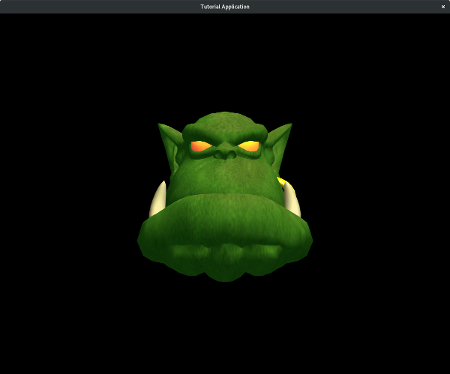
Coordinates Systems
Before we go on, let’s cover some basics of Ogre’s coordinate system. Ogre, like many other graphics engines, uses the x-z plane as the «floor» in a scene. This means that the y-axis is the vertical axis to ensure Ogre is using a right-handed coordinate system
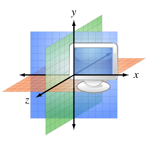
The x-axis starts with negative values to the left and increases to the right (passing through zero at the origin). The z-axis runs forwards and backwards. The positive direction of the z-axis points «out of the screen». So if a character walks towards the screen, then its z value will be increasing. Finally, the y-axis runs from the bottom to the top. Values that are «below ground» are negative. Don’t take these terms in parenthesis literally. You can put the ground wherever you want. It is just to help you orient yourself in the scene.
When you run your application, notice how your Ogre head is facing towards the camera down the positive z-axis. This is a property of the mesh itself and the orientation of the camera. Cameras are covered in a later tutorial. The Ogre head is sitting at the origin of our world, (0, 0, 0). The direction the head is facing by default is a result of which way it was facing when it was originally modeled. You can effectively change this from within Ogre as well, but it will require some knowledge of quaternions, which aren’t really covered until the Intermediate Tutorials.
Ogre uses a vector class to represent positions and directions. There are vectors defined for 2-4 dimensions. They are called Ogre::Vector2, Ogre::Vector3, and Ogre::Vector4 — Vector3 being the most commonly used by far. If you are not familiar with the concept of vectors it is highly recommended to learn a little before attempting these tutorials. Even though Ogre is an abstraction over many of the complications involved with OpenGL and DirectX, there is still no escaping some mathematical concepts. Vectors and basic linear algebra will be some of the most useful things you can learn if you intend to proceed with 3D rendering. This site has produced a nice primer on vectors focused on game programmers.
Adding Another Entity
It’s time to get back to the coding. With our first Entity, we did not specify the location we wanted anywhere. Many of the functions in Ogre have default parameters. The SceneNode::createChildSceneNode(external link) method can take three parameters, but we called it with none. The parameters are the name, position, and rotation of the SceneNode being created. We’ve already mentioned that Ogre generates a unique name for us. It also uses (0, 0, 0) as a default position.
First, let’s move the camera so we can fit more Entities on screen. Place this call right after you set the ambient light in createScene:
camNode->setPosition(0, 47, 222);
Now, let’s create another Entity and SceneNode, but this time we’ll give it a new position.
Entity* ogreEntity2 = scnMgr->createEntity(«ogrehead.mesh»);
SceneNode* ogreNode2 = scnMgr->getRootSceneNode()->createChildSceneNode(Vector3(84, 48, 0));
ogreNode2->attachObject(ogreEntity2);
Vector< 3, Real > Vector3
Definition: OgrePrerequisites.h:252
This is the same thing we did the first time, except we are now providing a Vector3 to our createChildSceneNode method. This will override the default position. Remember, the SceneNode’s position is always relative to its parent. In this case, the parent SceneNode is the root SceneNode, which is positioned at (0, 0, 0) by default.
Compile and run your application. Your Ogre head should have a buddy.
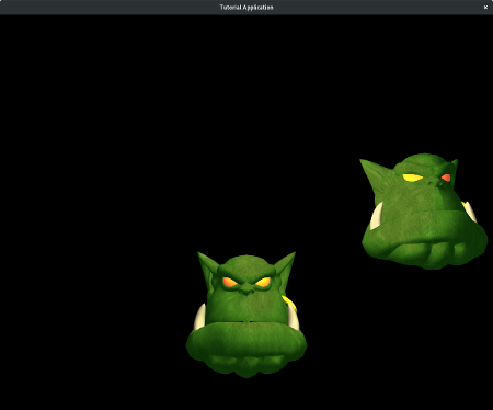
More About Entities
The Ogre::Entity class is very extensive. We will now introduce just a few more of its methods that will be useful. The Entity class has setVisible and isVisible methods. If you want an Entity to be hidden, but you still need it later, then you can use this function instead of destroying the Entity and rebuilding it later.
- Note
- Entities do not need to be pooled like they are in some graphics engines. Only one copy of each mesh and texture is ever loaded into memory, so there is not a big savings from trying to minimize the number of Entities.
The getName method returns the name of an Entity, and the getParentSceneNode method returns the SceneNode that the Entity is attached to. In our case, this would be the root SceneNode.
More About SceneNodes
The Ogre::SceneNode class is very complex. For now, we will only cover some of the most useful methods.
You can set the position after creating the node with setPosition. This is still relative to its parent node. You can move an objective relative to its current position by using translate.
SceneNodes are used to set a lot more than just position. They also manage the scale and rotation of objects. You can set the scale of an object with setScale. And you can use yaw, pitch, and roll to set the object’s orientation. You can use resetRotation to return the object to its default orientation. Finally, you can use rotate to perform more complicated rotations. This will again involve the use of quaternions, which will not be covered until the Intermediate Tutorials.
We’ve already used the attachObject method of a SceneNode. There are few more methods that are useful for dealing with the objects that are attached to a SceneNode. You can use numAttachedObjects to return the number of children attached to your node. You can use one of the many versions of Ogre::SceneNode::getAttachedObject to retrieve one of the SceneNode’s children. The method detachObject can be used to remove a specific child node, and detachAllObjects can be used to remove all.
Since the position of a child node is relative to its parent, it makes it very easy to move large groups of nodes together. For example, if we changed this line:
Class representing a node in the scene graph.
Definition: OgreSceneNode.h:61
virtual SceneNode * createChildSceneNode(const Vector3 &translate=Vector3::ZERO, const Quaternion &rotate=Quaternion::IDENTITY)
Creates an unnamed new SceneNode as a child of this node.
To this:
Then our new node would be parented directly to the SceneNode for our first Entity. This would mean that moving ogreNode would also move ogreNode2. It would also mean that the position of ogreNode2 would be relative to ogreNode.
If you’re having trouble with the idea of a relative location, then maybe an example will help. Let’s say we put our first node, ogreNode, at (10, 10, 10) and attach ogreNode2 directly to ogreNode. Then we set the position of ogreNode2 to be (-10, -10, -10). To figure out where ogreNode2 will be displayed we add its position to the position of its parent.
(10, 10, 10) + (-10, -10, -10) = (0, 0, 0)
ogreNode ogreNode2
parent child
So this means that ogreNode2 would actually be placed at (0, 0, 0) in our world, even though we set its position to (-10, -10, -10). If we detached this node and reattached it to the root SceneNode, then it would really be displayed at (-10, -10, -10), because:
(0, 0, 0) + (-10, -10, -10) = (-10, -10, -10)
root ogreNode2
parent child
Take a few seconds to soak this in. Relativity is hard. That’s why it took an Einstein to really figure it out.
Lastly, you can get a SceneNode or Entity by its name (if you gave it one), by calling getSceneNode or getEntity, which are Ogre::SceneManager methods. This way you don’t have to keep a pointer to all of your SceneNodes. You should generally only define pointers for nodes you will use often.
Changing An Entity’s Scale
We can set the scale of an Entity by calling setScale. This method allows us to provide a scale factor for each dimension. Let’s add another Ogre head and give it a different scale for demonstration. We will also position it so it fits well on the screen.
Entity* ogreEntity3 = scnMgr->createEntity(«ogrehead.mesh»);
SceneNode* ogreNode3 = scnMgr->getRootSceneNode()->createChildSceneNode();
ogreNode3->setPosition(0, 104, 0);
ogreNode3->setScale(2, 1.2, 1);
ogreNode3->attachObject(ogreEntity3);
Compile and run your application. You should see a fat Ogre head up top.
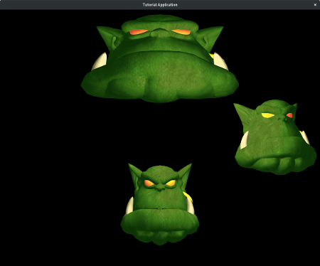
Rotating An Entity
An Entity’s rotation can be changed using the yaw, pitch, and roll methods.
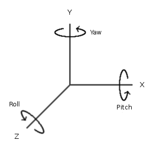
These methods will take either an Ogre::Degree or Ogre::Radian. As the picture demonstrates, rotation around the y-axis is called yaw, around the x-axis is called pitch, and around the z-axis is called roll. These are terms often used in describing the movements of an aircraft.
There is a well-known trick for remembering which direction is a positive rotation around an axis. It is called the right-hand rule. Point your thumb in the direction of the axis, and the direction your fingers curl towards is the positive direction. You can now see why these are often called «right-handed coordinate systems». There are about a million ways of doing the right-hand rule. This is why you might see a group of physics students throwing gang signs while doing their homework. They’re trying to remember which direction the magnetic field is headed.
Let’s put this to use and place a rotated Entity into our scene. We will also position it nicely.
Entity* ogreEntity4 = scnMgr->createEntity(«ogrehead.mesh»);
SceneNode* ogreNode4 = scnMgr->getRootSceneNode()->createChildSceneNode();
ogreNode4->setPosition(-84, 48, 0);
ogreNode4->roll(Degree(-90));
ogreNode4->attachObject(ogreEntity4);
Compile and run your application. We should now have a rotated Ogre head in our scene.
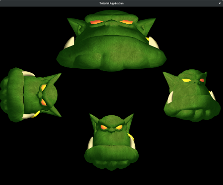
Plugins
Third-party plugins make it easy to integrate external libraries to add things like physics, input, and GUI systems. These libraries are used together to form a full game development environment. You might find this piecemeal approach a little strange, but it is a very common design pattern in large software projects. It is harder to comprehend at first, but it is a much more flexible approach when you want to start building more complicated scenes.
The SDK includes some of these third-party libraries. The Simple DirectMedia Layer is used to manage input events and distribute them to Ogre. You can also make use of Assimp through the AssimpCodec. This library allows you to load many popular geometry formats like .obj. There are other libraries (not included with the SDK) that offer functionality such as sound and physics.
Testing vs Release
When you’re building your application you can just leave every plugin activated. This will allow you to experiment with using them or not. But when you get ready to distribute a release build of your work, then you will want to deactivate any of the plugins you are not using.
Conclusion
You should now have a basic understanding of setting up an Ogre scene. This tutorial provided an introduction to three of the most important objects in Ogre: Ogre::Entity, Ogre::SceneNode, and Ogre::SceneManager. These objects allow us to render and manipulate a scene filled with 3D objects.
An Ogre::Entity represents anything that has an Ogre mesh. A Ogre::SceneNode is used to hold properties like location, scale, and rotation. It is also the anchor that attaches your Entities to your scene and allows them to be rendered on screen. Finally, The Ogre::SceneManager is the object that orchestrates it all. It has methods that allow you to create Entities and SceneNodes and keep them organized within a complicated scene.
Введение в основные принципы Ogre: объекты SceneManager, SceneNode и Entity.
Краткое введение
В этом руководстве мы познакомим вас с базовыми понятиями в Ogre: Менеджер сцены (SceneManager), Node (SceneNode) и Entity. В начале нашего обучения мы не будем углубляться в программирование, вместо этого мы сфокусируемся на главных понятиях и концепциях.
По мере изучения руководства вы будете понемногу добавлять код в ваше приложение и наглядно видеть результаты. Ничто не заменит реального опыта в программировании. Боритесь с желанием просто читать!
Необходимые знания
Это руководство подразумевает, что у вас есть знания программирования на C++, и вы в состоянии установить и скомпилировать приложение с помощью Ogre.
Это руководство также подразумевает, что вы создали проект, используя Ogre Wiki Tutorial Framework, либо вручную, используя CMake или Ogre AppWizard.
Первоначальный код
Для этого руководства мы будем использовать готовой шаблон кода. Не обращайте внимания на весь код, нас будет интересовать только тот, который мы будем добавлять в метод createScene. В следующих статьях мы дадим более глубокое объяснение принципам работы Ogre, но сейчас мы начнем с самого основного.
Прочитайте Setting up an Application, чтобы понять как создать и настроить проект под Ogre.
Создайте новый проект. Назовите его «Tutorial».
Добавьте к нему шаблон:
BaseApplication.h
BaseApplication.cpp
TutorialApplication.h
TutorialApplication.cpp
Вы можете скачать файлы здесь.
Или воспользуйтесь Ogre AppWizard.
В этом руководстве мы будем работать только с файлом TurtorialApplication.cpp и методом createScene().
TutorialApplication.cpp должен содержать следующий код (заголовочные комментарии удалены, чтобы не создавать путаницы):
#include "TutorialApplication.h"

TutorialApplication::TutorialApplication(void)
{
}

TutorialApplication::~TutorialApplication(void)
{
}

//-------------------------------------------------------------------------------------
void TutorialApplication::createScene(void)
{
    Ogre::Entity* ogreHead = mSceneMgr->createEntity("Head", "ogrehead.mesh");

    Ogre::SceneNode* headNode = mSceneMgr->getRootSceneNode()->createChildSceneNode();
    headNode->attachObject(ogreHead);

    // Set ambient light
    mSceneMgr->setAmbientLight(Ogre::ColourValue(0.5, 0.5, 0.5));

    // Create a light
    Ogre::Light* l = mSceneMgr->createLight("MainLight");
    l->setPosition(20,80,50);
}

#if OGRE_PLATFORM == OGRE_PLATFORM_WIN32
#define WIN32_LEAN_AND_MEAN
#include "windows.h"
#endif

#ifdef __cplusplus
extern "C" {
#endif

#if OGRE_PLATFORM == OGRE_PLATFORM_WIN32
    INT WINAPI WinMain( HINSTANCE hInst, HINSTANCE, LPSTR strCmdLine, INT )
#else
    int main(int argc, char *argv[])
#endif
    {
        // Create application object
        TutorialApplication app;

        try
        {
            app.go();
        }
        catch( Ogre::Exception& e )
        {
#if OGRE_PLATFORM == OGRE_PLATFORM_WIN32
            MessageBox( NULL, e.getFullDescription().c_str(), "An exception has occured!",
                        MB_OK | MB_ICONERROR| MB_TASKMODAL);
#else
            std::cerr << "An exception has occured: " << e.getFullDescription().c_str() << std::endl;
#endif
        }

        return 0;
    }

#ifdef __cplusplus
}
#endif
Давайте скомпилируем и запустим программу, чтобы убедится что все настроено правильно. Используйте клавиши WASD для передвижения, и мышь чтобы осмотреться. Нажав клавишу Esc вы закроете приложение.
Решение проблем
Если у вас возникли проблемы при компиляции, еще раз прочитайте Setting Up An Application, для того чтобы убедится, что вы правильно настроили компилятор. Также взгляните в файл Ogre.log, там могут находиться полезные сведения. Еще вы можете поискать решение вашей проблемы на форумах посвященных Ogre. Вполне вероятно ваша проблема уже возникала у других. Если по вашей проблеме нет информации, прочитайте правила форума и не стесняйтесь спрашивать. Если вы хотите, чтобы вам быстро ответили, не ленитесь выложить файл Ogre.log, сообщения об ошибках, и/или отладочную информацию.
В следующих статьях не будет секции «Решение Проблем», поэтому обратите особое внимание на следующие абзацы.
Проблема с Message Box
Если вы используете Visual Studio с включенной в проекте поддержкой Unicode, может возникнуть такая ошибка:
error C2664: 'MessageBoxW' : cannot convert parameter 2 from 'const char *' to 'LPCWSTR' Types pointed to are
unrelated; conversion requires reinterpret_cast, C-style cast or function-style cast
Проблема в том, что функция MessageBox ожидает строку в формате Unicode (в нашем случае), а мы отправляем ей строку в ANSI. Чтобы поправить это, измените следующую строку:
MessageBox( NULL, e.what(), "An exception has occured!", MB_OK | MB_IConerror | MB_TASKMODAL);
на эту:
MessageBoxA( NULL, e.what(), "An exception has occured!", MB_OK | MB_IConerror | MB_TASKMODAL);
Или вы можете исправить это, сменив текстовый формат в вашем компиляторе с Unicode на ANSI. Однако в таком случае не будет поддержки других языков.
Причина в том что функция MessageBox ссылается на MessageBoxA (ANSI) или MessageBoxW (Widechar/Unicode), в зависимости от конфигурации вашего проекта. Мы исправим эту ошибку явно указав использовать ANSI формат функции.
Отсутствие файлов конфигурации или DLL
Если ваше приложение собралось но при запуске выдает ошибку в связи с отсутствием DLL библиотек или конфигурационных файлов (*.cfg), тогда вы вероятно забыли их скопировать из каталога OgreSDK. В Visual Studio, собранные .exe файлы обычно помещаются в каталоги [ProjectFolder]binrelease и [ProjectFolder]bindebug для режима Release и Debug соответственно. Вы должны скопировать все *.dll и *.cfg файлы из папки OgreSDK в эти каталоги. То есть копируйте файлы из [OgreSDK]binrelease в [ProjectFolder]binrelease и из [OgreSDK]bindebug в [ProjectFolder]bindebug. Также отредактируйте resources.cfg и укажите в нем правильные пути. В следующей секции разберем это более детально.
Проблемы с плагинами или ресурсами
Убедитесь что plugins.cfg и resources.cfg находятся в том же каталоге, что и собранный .exe файл. Plugins.cfg указывает огру доступные библиотеки для рендеринга (Direct3D9, OpenGL). Resources.cfg используется ExampleApplication и указывает пути на текстуры, меши и скрипты. Оба этих файла текстовые, отредактируйте их и убедитесь что указанные в них пути ведут куда надо. В противном случае окно с настройками Ogre не найдет библиотек для рендера или возникнет ошибка на экране или в Ogre.log, что выглядит примерно так:
Description: ../../Media/packs/OgreCore.zip - error whilst opening archive: Unable
to read zip file
В таком случае откройте файл resources.cfg и измените пути, которые указывают на каталоги в папке Media находящуюся в папке Ogre. Заметим, что использовать переменные окружения, вроде $(SomeVariable), нельзя.
Невозможно запустить приложение в Visual Studio или CodeBlocks
Если вы используете Visual Studio или Visual C++, и у вас возникли проблемы с запуском компиляции приложения, проблема скорее всего в настройках дебаггера. Если вы запустили приложение из среды разработки (нажав кнопку Run, или Start debugging) и получили сообщение о отсутствующих конфигурационных файлах (*.cfg), значит рабочий каталог не установлен.
Решение этой проблемы зависит от того, какую версию Visual C++ вы используете, поэтому точного решения здесь нет, но основные шаги должны быть теми же самыми. Правый клик по вашему проекту в «solution explorer», (не по самому пункту «solution») и выбираем «properties». Где то в «Configuration Properties» должна быть опция «Debugging». Там выбираем поле «Working directory». Там указываете директорию, куда сохраниться скомпилированный .exe файл.
Если вы не представляете, что писать в этом поле, обратите внимание на поле «Command», которое также должно находится в «Debugging Options». Для примера, в Visual C++ 2003, поле «Command» должно содержать что то вроде «….bin$(ConfigurationName)$(TargetFileName)». Для поля «Working Directory» мы копируем поле «Command» удалив $(TargetFileName). Таким образом в «Working Directory» будет «….bin$(ConfigurationName)». Содержимое этого поля зависит от того какую версию Visual C++ вы используете, а также от того чем вы собираете ваше приложение, так что перед этим обязательно проверьте что содержится в поле «Command». Проверьте что вы изменили «Working Directory» для обоих конфигураций, как Release, так и Debug.
В Visual C++ 2005 нужные поля вероятно будут располагаться немного по другому. Для начала попробуйте указать в этом поле каталог «….bin$(ConfigurationName)», если приложение все еще не запускается — поэкспериментируйте или попробуйте спросить совета на форумах посвященных Ogre.
Если вы используете Code::Blocks, тогда вам необходимо сделать то же самое. Правый клик по вашему проекту, выбираем «Properties…», переходим на вкладку «Build targets», и изменяем содержимое поля «Execution working dir:» указывая в нем тот же каталог в который помещаются исполняемые файлы (см. поле Output filename).
Причина по которой мы делаем это — Ogre ожидает, что некоторые файлы будут находится в том же каталоге, что и .exe файл. И без настройки рабочей директории (working directory), приложение не запустится.
Итак вы запустили ваше приложение, теперь удалим весь код внутри функции createScene() оставив саму функцию. Мы будем писать код внутри этой функции и давать объяснение к каждой строке нашего кода.
Как работает Ogre
Основы SceneManager
Все что вы видите в окне вашего приложения, все управляется с помощью SceneManager. Когда вы добавляете объект на сцену, класс SceneManager берет на себя управление его позиционированием. Когда вы создаете объект Camera, чтобы видеть сцену (в следующих руководствах мы рассмотрим это), то за ним опять же следит SceneManager. Когда вы создаете объекты Plane, Billboards, Lights и все остальное, то SceneManager также берет на себя управление их положением.
Есть несколько типов SceneManager. Есть SceneManager предназначенный для отрисовки ландшафта (Terrain), есть для отрисовки BSP Maps и так далее. Вы можете увидеть несколько типов SceneManager перечисленных здесь. По мере прохождения руководства мы рассмотрим это более подробно.
Основы Entity
Entity — это один из типов объектов которые вы можете добавить к сцене. Entity представляет собой 3D объекты. Робот будет объектом класса Entity, рыба, ландшафт по которому перемещаются ваши персонажи — все это Entity (разве что ландшафт представляет собой очень большой Entity). Источники света, источники частиц, камеры объектами Entity не являются.
Следует упомянуть одну вещь об Ogre, он разделяет сами объекты с их расположением и ориентацией. Это означает то, что к сцене объект Entity напрямую добавить невозможно. Вместо этого, мы можем добавить Entity к объекту SceneNode, которая уже будет содержать информацию о его положении.
Основы SceneNode
Как уже упоминалось выше, класс SceneNode содержит информацию о положении и ориентации объектов которые к нему присоединены. Когда вы создаете объект Entity, он не будет отображаться на экране, пока вы не привяжете его к SceneNode. Но и SceneNode по себе не является объектом, отображающимся на экране. Только в том случае если вы создадите SceneNode и прикрепите к нему Entity (или другой объект), вы имеете шанс действительно что-то увидеть.
К одному SceneNode можно присоединить любое количество объектов. Давайте предположим что у вас есть персонаж который ходит по кругу, и вы хотите, чтобы он освещал окружающее пространство. Для того, чтобы сделать это, сначала нужно создать объект SceneNode, потом создадим Entity которое будет представлять собой нашего персонажа и прикрепим его к SceneNode. Затем мы создадим источник света (Light) и прикрепим его к той же SceneNode, что и персонажа. SceneNode также может быть прикреплена к другим SceneNodes что позволяет создавать иерархию (наследование классов). В следующем руководстве мы расскажем больше об использовании SceneNode.
Один важный момент касающийся SceneNodes. Позиция SceneNode всегда относительна к ее предку, и каждый SceneManager содержит корневой SceneNode к которому прикреплены остальные SceneNode.
Ваше первое приложение на Ogre
Вернемся к коду который мы создали ранее. Найдем функцию TutorialApplication::createScene. Как мы упоминали ранее, изменения будут происходить только в этой функции. Первое что мы сделаем, это установим уровень освещенности самой сцены (ambient light), чтобы видеть результаты нашего труда (в темноте же ничего не видно ). Для этого вызываем функцию setAmbientLight и указываем нужный нам цвет. Конструктор ColorValue принимает три параметра (RGB) для красного, зеленого и голубого цветов. Значение колеблется в промежутке от 0 до 1. Добавим этот код к createScene:
mSceneMgr->setAmbientLight(Ogre::ColourValue(1.0, 1.0, 1.0));
Следующее что мы сделаем, это создадим Entity. Вызываем метод createEntity объекта SceneManager:
Ogre::Entity* ogreHead = mSceneMgr->createEntity("Head", "ogrehead.mesh");
У вас наверняка возникли некоторые вопросы. Первый откуда взялся mSceneMgr, и что за параметры мы передаем в функцию. Переменная mSceneMgr является ссылкой на текущий объект класса SceneManager (это для нас настроено в BaseApplication). Первый параметр функции createEntity это название объекта который мы создаем. Все экземпляры Entity должны иметь уникальное название. Так как при попытке создать два объекта с одинаковым именем, возникнет ошибка. Параметр «ogrehead.mesh» указывает меш (проще говоря сохраненную 3d модель), который будет использован для Entity. В нашем случае «ogrehead.mesh» есть в папке Ogre SDK, и оттуда меш и берется. Загрузка ресурсов будет описана в следующих статьях. Сейчас мы используем для загрузки ресурсов BaseApplication.
Итак Entity мы создали, теперь нам необходимо создать SceneNode, к которому мы прикрепим наш Entity. Каждый SceneManager имеет корневую SceneNode, мы создадим дочернюю к нему SceneNode.
Ogre::SceneNode* headNode = mSceneMgr->getRootSceneNode()->createChildSceneNode("HeadNode");
Это длинное выражение сперва вызывает getRootSceneNode текущего объекта SceneManager. Затем он вызывает метод createChildSceneNode корневой SceneNode. Параметр передаваемый createChildSceneNode это имя SceneNode которую мы создаем. Как и Entity, два экземпляра SceneNode не могут иметь одинаковые имена.
И наконец мы присоединяем Entity к SceneNode, для того чтобы указать голове огра место где она будет находиться:
headNode->attachObject(ogreHead);
Вот и все! Скомпилируйте и запустите ваше приложение. Вы должны увидеть голову огра на вашем экране.

Векторы и координаты
Перед тем как мы пойдем дальше, нужно понять что такое координаты на экране и как работают векторы в Ogre. Ogre (подобно многим графическим движкам) использует координатные оси X и Z для горизонтальных плоскостей, и Y для вертикальной координаты. Если ориентироваться по монитору, то ось X проходит слева направо, с правой стороны положительная часть оси. Ось Y проходит снизу вашего монитора на верх, сверху положительная часть оси. Ось Z берет свое начало глубоко в недрах монитора и выходит из него, вне монитора положительная часть оси.

Заметим, что голова огра сейчас обращена прямо к нам по направлению оси Z, как так? На это влияют свойства самого меша. Камеры рассматриваются позже в следующем руководстве, но сейчас стоит учесть, что голова огра находится в начале координат (0,0,0), и мы видим ее спереди. Стандартное направление головы берется из самой модели, направление, которое было задано при ее создании. Ogre не может предполагать как ориентирована ваша модель. Каждый меш который мы загружаем может быть ориентирован по разному.
Для того, чтобы задать позицию и направление Ogre использует класс Vector (Вектор). Векторы определены в трех классах для 2 (Vector2), 3 (Vector3) и 4 (Vector4) измерений, из них чаще всего используется Vector3. Если вы незнакомы с векторами, стоит освежить их в памяти, прежде делать что нибудь серьезное. Незнание векторов станет серьезной проблемой, когда вы начнете делать что-либо серьезное.
Добавление другого объекта
Поняв как работает система координат, вернемся к нашему коду. Ни в одной из тех трех строк, что мы написали, не указано точное расположение головы огра. Большинство функций в Ogre используют для этого значения по умолчанию. Для примера функция SceneNode::createChildSceneNode имеет три параметра: название SceneNode, ее позиция и исходное положение (разворот). Позиция, как вы уже убедились, имеет координаты (0,0,0). Давайте создадим еще один объект SceneNode, но сейчас укажем ее начальное расположение:
Ogre::Entity* ogreHead2 = mSceneMgr->createEntity( "Head2", "ogrehead.mesh" );
Ogre::SceneNode* headNode2 = mSceneMgr->getRootSceneNode()->createChildSceneNode("HeadNode2", Ogre::Vector3(100, 0, 0));
headNode2->attachObject( ogreHead2 );
Это должно быть уже знакомо. Мы сделали то же самое что и в прошлый раз, кроме двух вещей. Первая — мы назвали SceneNode и Entity немного по другому. Вторая — мы указали начальное положение смещенное на 100 единиц по оси X относительно корневой SceneNode (напомню что координаты SceneNode заданы относительно их предков). Скомпилируйте и запустите программу. Сейчас на сцене две головы огра расположенные бок о бок. Можно сдвинутся немного назад используя клавишу «S», или воспользоваться мышкой, чтобы их увидеть.
Подробней про Entity
Класс Entity довольно обширный, и мы не сможем затронуть все аспекты в рамках статьи, но расскажем достаточно для начала. В классе Entity есть несколько функций которые могут понадобиться прямо сейчас.
Первая — Entity::setVisible и Entity::isVisible. Мы можем скрыть или включить отображение головы на экране просто вызвав эту функцию. Если необходимо скрыть голову, но позже отобразить ее, тогда имеет смысл воспользоваться этой функцией, вместо того чтобы удалять и создавать ее заново. Обратите внимание, что во всем этом не нужно использовать Entitiy. В память загружается только одна копия любого объекта или текстуры, поэтому уменьшая количество Entity вы не сэкономите много памяти. Единственное на чем вы сэкономите в таком случае, это отсутствие затрат на создание и удаление объекта Entity, а они относительно малы.
Функция getName возвращает название объекта Entity, функция getParentSceneNode возвращает SceneNode к которой присоединен объект Entity.
Подробней про SceneNode
Класс SceneNode достаточно большой. Довольно много вещей реализуются с помощью SceneNode, так что сейчас мы рассмотрим только несколько из часто используемых возможностей.
Для того чтобы получить или указать текущее расположение SceneNode есть функции getPosition и setPosition (они возвращают координаты относительно родительской SceneNode). Метод translate позволяет передвинуть объект относительно его текущей позиции.
Кроме позиционирования SceneNode позволяет вращать и масштабировать объект. Для масштабирования применяется функция scale. Для вращения относительно каждой из координатных осей используются функции pitch, yaw и roll. Вы можете воспользоваться resetOrientation, чтобы отменить все вращение примененные к объекту. Вы также можете использовать функции setOrientation, getOrientation и rotate для более гибкого вращения. Тему Кватернионы (Quaternions) мы поднимем в более поздних статьях.
Вы уже знакомы с функцией attachObject. Эти связанные функции также будут довольно полезны, если вы ищете способ управлять объектами которые присоединены к SceneNode: numAttachedObjects, getAttachedObject (есть несколько версий этой функции), detachObject (тоже несколько версий), detachAllObjects. Также существует целый набор функций для работы с предками и потомками SceneNode.
Поскольку все позиционирование и перемещение выполнятся относительно предка SceneNode, мы можем заставить две SceneNode двигаться вместе. Итак у нас получился такой код:
mSceneMgr->setAmbientLight(Ogre::ColourValue(1.0, 1.0, 1.0));
Ogre::Entity* ogreHead = mSceneMgr->createEntity(«Head», «ogrehead.mesh»);
Ogre::SceneNode* headNode = mSceneMgr->getRootSceneNode()->createChildSceneNode(«HeadNode»);
headNode->attachObject(ogreHead);
Ogre::Entity* ogreHead2 = mSceneMgr->createEntity( «Head2», «ogrehead.mesh» );
Ogre::SceneNode* headNode2 = mSceneMgr->getRootSceneNode()->createChildSceneNode( «HeadNode2», Ogre::Vector3( 100, 0, 0 ) );
headNode2->attachObject( ogreHead2 );
Если мы изменим 6 строку с этой:
Ogre::SceneNode* headNode2 = mSceneMgr->getRootSceneNode()->createChildSceneNode( "HeadNode2", Ogre::Vector3( 100, 0, 0 ) );
на эту:
Ogre::SceneNode* headNode2 = headNode->createChildSceneNode( "HeadNode2", Ogre::Vector3( 100, 0, 0 ) );
То укажем, что headNode2 является потомком headNode. При перемещении headNode, headNode2 также будет перемещатся, но при передвижении headNode2, headNode останется на месте. Для примера этот код будет перемещать только headNode2:
headNode2->translate( Ogre::Vector3( 10, 0, 10 ) );
Следующий код заставит перемещаться headNode, но учитывая то что headNode2 является потомком headNode, headNode2 будет перемещаться вместе с headNode.
headNode->translate( Ogre::Vector3( 25, 0, 0 ) );
Этот код заставит перемещаться headNode, но учитывая то что headNode2 является потомком headNode, headNode2 будет перемещаться вместе с headNode. Если у вас возникли проблемы с пониманием этого, давайте разберем простой пример. Мы начнем с корневой SceneNode и пойдем вниз по иерархии SceneNode. Давайте предположим (возьмем наш случай), мы начнем с headNode (0, 0, 0) и переместим ее (translate) на (25, 0, 0). Таким образом новая позиция headNode станет (25, 0, 0) относительно его предка. Позиция headNode2 (100, 0, 0) мы перемещаем ее на (10, 0, 10). Итого новая позиция headNode2 станет (110, 0, 10) относительно его предка (headNode).
Теперь представим где будут находится эти SceneNode. Начнем с корневой SceneNode. Ее позиция всегда (0, 0, 0). Сейчас положение headNode = (root + headNode): (0, 0, 0) + (25, 0, 0) = (25, 0, 0). Ничего удивительного.
headNode2 является потомком headNode, таким образом ее позиция будет (root + headNode + headNode2): (0, 0, 0) + (25, 0, 0) + (110, 0, 10) = (135, 0, 10).
Это всего лишь пример того как наследуются позиции SceneNode. Впрочем необходимость вычислять абсолютные позиции SceneNode возникает довольно редко. Под конец заметим, что вы можете получить как объекты SceneNode так и Entity используя методы getSceneNode и getEntity объекта SceneManager. Следовательно нет необходимости хранить на них ссылки. Имеет смысл сохранять ссылки только на те объекты, которыми вы часто пользуетесь.
Дополнительные рекомендации
К этому моменту у вас должно сложится общее представление о Entities, SceneNodes и SceneManager. Мы предлагаем начать с кода, расположенного выше, и добавлять и удалять головы огра со сцены. Как только вы закончите «баловаться», удалите все содержимое функции createScene и давайте поэкспериментируем со следующими фрагментами кода:
Масштабирование (Scale)
Чтобы масштабировать модели, воспользуемся методом SceneNode->scale. Пропробуйте изменять значения которые мы передаем в функцию scale, и посмотрите, что у вас получится:
mSceneMgr->setAmbientLight(Ogre::ColourValue(1.0, 1.0, 1.0));
Ogre::Entity* ogreHead = mSceneMgr->createEntity(«Head», «ogrehead.mesh»);
Ogre::SceneNode* headNode = mSceneMgr->getRootSceneNode()->createChildSceneNode(«HeadNode»);
headNode->attachObject(ogreHead);
headNode->scale( .5, 1, 2 );
Ogre::Entity* ogreHead2 = mSceneMgr->createEntity( «Head2», «ogrehead.mesh» );
Ogre::SceneNode* headNode2 = mSceneMgr->getRootSceneNode()->createChildSceneNode( «HeadNode2», Ogre::Vector3( 100, 0, 0 ) );
headNode2->attachObject( ogreHead2 );
headNode2->scale( 1, 2, 1 );

Вращение (Rotations)
Вы можете вращать объект используя функции yaw, pitch, и roll передавая им в качестве параметров угол вращения в градусах или радианах. В огре это объекты Degree и Radian соответственно. pitch это вращение вокруг оси X, yaw вращает объект вокруг оси Y а roll — вокруг оси Z. Используйте правую руку для удобства: поместите ваш палец в направлении оси, сожмите оставшиеся пальцы. Направление согнутой части руки — положительное вращение вокруг оси:
Попробуем изменить значение объекта Degree, которое мы передаем и объединим несколько трансформаций:
mSceneMgr->setAmbientLight(Ogre::ColourValue(1.0, 1.0, 1.0));
Ogre::Entity* ogreHead = mSceneMgr->createEntity(«Head», «ogrehead.mesh»);
Ogre::SceneNode* headNode = mSceneMgr->getRootSceneNode()->createChildSceneNode(«HeadNode»);
headNode->attachObject(ogreHead);
headNode->yaw( Ogre::Degree( -90 ) );
Ogre::Entity* ogreHead2 = mSceneMgr->createEntity( «Head2», «ogrehead.mesh» );
Ogre::SceneNode* headNode2 = mSceneMgr->getRootSceneNode()->createChildSceneNode( «HeadNode2», Ogre::Vector3( 100, 0, 0 ) );
headNode2->attachObject( ogreHead2 );
headNode2->pitch( Ogre::Degree( -90 ) );
Ogre::Entity* ogreHead3 = mSceneMgr->createEntity( «Head3», «ogrehead.mesh» );
Ogre::SceneNode* headNode3 = mSceneMgr->getRootSceneNode()->createChildSceneNode( «HeadNode3», Ogre::Vector3( 200, 0, 0 ) );
headNode3->attachObject( ogreHead3 );
headNode3->roll( Ogre::Degree( -90 ) );
В Microsoft Visual Studio 2010 может возникнуть ошибка «Degree is an undeclared identifier». Это может быть исправлено с помощью вызова функции Ogre::Degree, позволяя компилировать вращение.
Среда разработки в Ogre
Большинство файлов (.dll и .cfg) на которые мы ссылаемся в этом туториале можно найти в каталоге OgreSDK/bin версии release и debug. Ваши программы в режиме Debug должны использовать файлы из каталога debug OgreSDK, в режиме Release — файлы из каталоге release соответственно.
В этой части руководства в основном рассматривается платформа Windows. Для Linux эта же информация применима по большей части, но к примеру библиотеки будут иметь расширение .so и могут находится в других каталогах. Также некоторые вещи могут немного отличатся. Со всеми возникающими вопросами идем на форум.
Библиотеки (.dll) и плагины
Получив представление об окружении Ogre, стоит объяснить как библиотеки Ogre работают в целом, чтобы упростить вам дальнейшую жизнь.
Ogre разделен на 3 большие группы библиотек: основная библиотека, плагины и внешние библиотеки.
Основная библиотека
Основная группа библиотек состоит из самой библиотеки и библиотек которые она использует. Основная библиотека Ogre — OgreMain.dll. Эта dll требует некоторые другие библиотеки, такие как cg.dll. Эти библиотеки использует каждое приложение Ogre без исключений.
Плагины
Вторая группа библиотек это плагины. Довольно большая часть функциональности Ogre вынесена в подключаемые библиотеки и может быть включена или выключена в зависимости от потребностей. Базовые плагины которые поставляются вместе с Ogre имеют в названии файла префикс «Plugin_». Также вы можете создавать собственные плагины если у вас есть в этом необходимость, но в этом руководстве этой темы мы не коснемся. Для системы рендеринга (OpenGL, DirectX) Ogre также использует плагины. Эти плагины имеют префикс «RenderSystem_». Эти плагины существуют для того, чтобы вы могли добавлять или удалять системы редеринга из вашего приложения. Особенно полезно это если вы пишете шейдеры или что нибудь зависимое от (для примера) OpenGL и вам необходимо запретить возможность запускать приложение под DirectX. В таком случае можно просто удалить соответствующий плагин RenderSystem. В дополнение, если вашей целью является разработка под нестандартную платформу, вы можете написать собственный плагин для RenderSystem, но в нашем руководстве мы этого не коснемся. В следующей секции будет рассказано как удалить плагины.
Внешние и вспомогательные библиотеки
Третья группа библиотек это внешние библиотеки. Ogre сам по себе является просто библиотекой для рендеринга. Он не занимается отрисовкой пользовательского интерфейса, обработкой сообщений от мыши и клавиатуры, обработкой физики и так далее. Для всего этого вам необходимо использовать другие библиотеки.
Демонстрационные приложения Ogre и SDK версия Ogre включают в себя некоторые такие библиотеки.
— Обработку сообщений клавиатуры и мыши берет на себя OIS (система ввода). Эта библиотека содержится в файле OIS.dll.
— Cg («C» для графики), используемая CgProgramManager, находится в Cg.dll.
Также существуют другие библиотеки (не включенные в SDK) которые расширяют функциональность Ogre (такие как звук и обработка физики) по которым вы можете найти информацию на вики и форумах.
Мораль истории
Моралью этой истории является то, что при тестировании приложения локально, не стоит удалять ничего, чтобы проверить как ваше приложение работает со всем этим. Когда вы будете готовы распространять свои приложения, вам необходимо собрать его в Release режиме и включить в дистрибутив Release библиотеки которые использует ваша программа.
Если ваше приложение не использует CgProgramManager, но использует OIS, тогда нет нужды включать в дистрибутив библиотеки от Cg и CgProgramManager, но о библиотеке OIS необходимо позаботится, иначе приложение не запуститься.
Файлы конфигурации
Ogre использует при запуске несколько файлов конфигурации. Они контролируют какие плагины будут загружены, где находятся ресурсы приложения и тому подобное. Мы быстро пробежимся по каждому из таких конфигурационных файлов и объясним что они делают. Как обычно, если у вас возникают дополнительные вопросы, добро пожаловать на форум.
plugins.cfg
Файл содержит ссылки на плагины которые использует приложение. Чтобы добавить или удалить плагин из приложения просто отредактируйте этот файл. Удалить плагин можно убрав из этого файла соответствующую строку или закомментировав ее добавив # в начале строки. Включить плагин можно добавив строку вида «Plugin=[имя_плагина]». Не нужно дописывать «.dll» в конце названия плагина. Префиксы «RenderSystem_» или «Plugin_» тоже не надо указывать. Вы также можете указать каталог где находятся плагины изменив параметр «PluginFolder». Можно указывать как абсолютные так и относительные пути, но переменные окружения типа $(SomeVariable) использовать нельзя.
resources.cfg
Файл содержит список каталогов в которых Ogre ищет ресурсы. Ресурсы включают в себя скрипты, 3d объекты, текстуры и так далее. В этом файле аналогично можно указывать как абсолютные так и относительные пути, но нельзя переменные окружения типа $(SomeVariable). Заметим что Ogre не ищет ресурсы в подкаталогах, так что придется прописать путь к каждой из папок. К примеру если у вас есть иерархия каталогов вроде «resmeshes» и «resmeshessmall», в ресурсный файл придется добавить две строки содержащие пути к обоим каталогам.
media.cfg
В файле содержится более детальная информация о ресурсах. Не думаю что сейчас у вас будет необходимость изменять этот файл, так что мы опустим детали. Больше информации ищите на форумах посвященных Ogre.
ogre.cfg
Это сгенерированный Ogre файл конфигурации экрана. Этот файл хранит ваши индивидуальные настройки графики. Этот файл не стоит передавать с вашей программой, у других возможно будут совсем другие настройки. Кстати не стоит редактировать его руками, оставьте эту задачу окну конфигурации Ogre.
quake3settings.cfg
Используется BSPSceneManager. Сейчас мы не используем этот файл, поэтому его описание мы пропустим. Этот файл тоже нет смысла распространять если вы не используете BSPSceneManager, но если даже используете, то его содержимое может полностью различаться в зависимости от требований вашего приложения.
Это были все конфигурационные файлы, которые используются непосредственно Ogre. Для запуска Ogre необходимы файлы «plugins.cfg», «resources.cfg», и «media.cfg». В следующих руководствах мы расскажем больше о том как изменить их расположение и какие дополнительные возможности они предоставляют.
Заключение
На этот момент у вас уже должно сложится общее представление о классах SceneManager, SceneNode и Entity. Вы не должны быть знакомы со всем функциями, которые мы упоминали. Так как это базовые объекты и мы будем использовать их довольно часто. В следующих руководствах вы получите о них более полное представление. Вы также познакомились с тем как настраивать Ogre в вашем проекте.
Главный переводчик: alex(x)
Редактор: proVIDec (UnitArt)
unitart.org совместно с ogre3d.ru
Оригинальный вариант статьи вы можете увидеть на ogre3d.org.
Follow this simple guide to quickly get started using OGRe.
Installation
To get OGRe, use one of the following methods:
- pip (recommended)
- easy_install
- git
$ git clone http://github.com/dmtucker/ogre.git
$ cd ogre
$ python setup.py install
Note
This method requires separate installation(s) for dependencies!
Usage
To use OGRe, you must import it into your module:
Next, create an OGRe instance with your API credentials:
retriever = OGRe(
    keys={
        'Twitter': {
            'consumer_key': 'xxxxxxxxxxxxxxxxxxxxxx',
            'access_token': 'xxxxxxxxxxxxxxxxxxxxxxxxxxxx' +
                            'xxxxxxxxxxxxxxxxxxxxxxxxxxxx' +
                            'xxxxxxxxxxxxxxxxxxxxxxxxxxxx' +
                            'xxxxxxxxxxxxxxxxxxxxxxxxxxxx'
        }
    }
)
Finally, make queries using the .get method.
Note
“The [Twitter] Search API is not complete index of all Tweets,
but instead an index of recent Tweets.
At the moment that index includes between 6-9 days of Tweets.”
OGRe may be also be executed directly as shown below.
or (if OGRe was installed with pip)
As one would expect, API keys are necessary whenever OGRe is run, and they may
be passed one of two ways: the keys parameter or via environment variables.
If the latter is preferred, the following table shows what variables are
needed for each source:
| Source | Key Variable(s) |
|---|---|
| TWITTER_CONSUMER_KEY, TWITTER_ACCESS_TOKEN |
Examples
To find 50 image-less Tweets posted within 1km of Twitter headquarters, use:
retriever.fetch(
    sources=('Twitter',),
    media=('text',),
    keyword='',
    quantity=50,
    location=(37.781157, -122.398720, 1, 'km'),
    interval=None
)
Note
Either a keyword or location is required.
To issue the same query directly from the command line, use the following:
$ python -m ogre --keys "{
>   'Twitter': {
>     'consumer_key': '<Insert Twitter Consumer Key.>',
>     'access_token': '<Insert Twitter Access Token.>'
>   }
> }
> --sources Twitter
> --media text
> --quantity 50
> --location 37.781157 -122.398720 1 km
Alternatively, environment variables are checked when keys are unspecified.
$ export TWITTER_CONSUMER_KEY='<Insert Twitter Consumer Key.>'
$ export TWITTER_ACCESS_TOKEN='<Insert Twitter Access Token.>'
$ python -m ogre --sources Twitter --media text
> --quantity 50 --location 37.781157 -122.398720 1 km
See also
For a description of all available command line arguments, run:
Results return as a single GeoJSON FeatureCollection.
So, the example above could return:
{
    "type": "FeatureCollection",
    "features": [
        {
            "geometry": {
                "type": "Point",
                "coordinates": [
                    -122.3970807,
                    37.77541704
                ]
            },
            "type": "Feature",
            "properties": {
                "source": "Twitter",
                "text": "Sending good thoughts to my babe @annecurtissmith...",
                "timestamp": "2014-04-04T02:03:28.431000Z"
            }
        },
        {
            "geometry": {
                "type": "Point",
                "coordinates": [
                    -122.41160509,
                    37.78093192
                ]
           },
             "type": "Feature",
            "properties": {
                "source": "Twitter",
                "text": "I'm at Huckleberry Bicycles...",
                "timestamp": "2014-04-04T02:03:13.190000Z"
            }
        },
        ...
    ]
}
Say we wanted to run the same query and possibly have images returned too.
Additional mediums can be specified with subsequent media flags like this:
$ python -m ogre
> --sources Twitter
> --media text --media image
> --quantity 50
> --location 37.781157 -122.398720 1 km