- Главная
- Горелки для котлов отопления
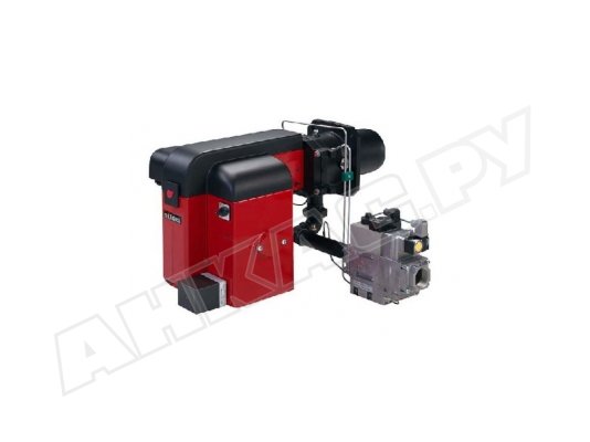
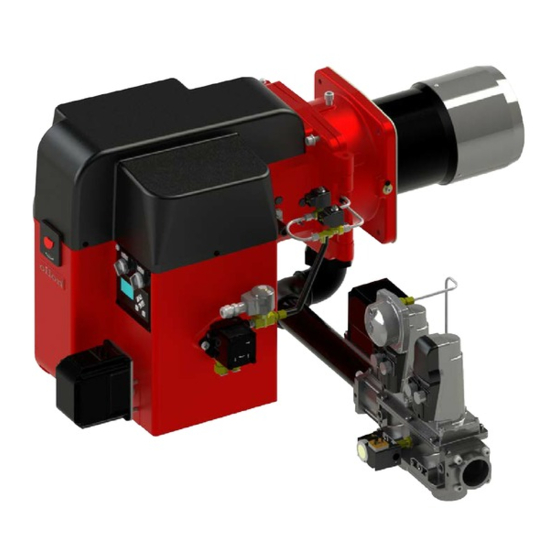
- Газовая горелка Oilon GP- 50 H
код на сайте: 27452
Oilon
, Финляндия
Цена:
Нет цены
Запросить цену

Краткие характеристики
- газовая
- одноступенчатая
- от 200 до 800 кВт
- 400 В
- IP 20
Вес и габариты
- 41 кг
- 45x50x95 см
Описание товара
Природный газ:
Сетевое давление на входе в горелку: 20 — 150/360 мбар.
Температура газа на входе в газовые клапаны: -15…+40 °C.
Сжиженный газ:
Сетевое давление на входе в горелку: 30 — 150/360 мбар.
Температура газа на входе в газовые клапаны: 0…+40 °C.
Основные характеристики
Вид горелки:
газовая
Тип горелки:
одноступенчатая
Мощность горелки:
от 200 до 800 кВт
Электропитание:
400 В
Класс пылевлагозащиты:
IP 20
Рабочая температура:
от 0 до +40 °C
Тип соединения:
?
DN 40
Вес:
41 кг
Габариты:
45x50x95 см
* Технические характеристики и комплект поставки могут быть изменены производителем без предварительного уведомления.
-
Горелки для котлов отопления
-
Газовые горелки
Аналоги
Аналоги не найдены
Газовая горелка Oilon GP- 50 H
Скрол
![]()
Продолжая использовать наш сайт, вы даете согласие на обработку файлов Cookies и других данных, в соответствии с
Политикой конфиденциальности и Пользовательским соглашением.
Вся информация на сайте – собственность ankas.ru.
Публикация любой информации с сайта ankas.ru без разрешения запрещена.
Информация на сайте ankas.ru не является публичной офертой.
© Компания «Анкас», 2013-2023. Все права защищены.
-
Измерительные приборы: манометры, термометры, датчики, термопары
-
Датчики, манометры, реле и преобразователи давления
- Регуляторы давления
- Датчики давления
- Преобразователи давления
- Реле давления
- Манометры
-
Датчики и реле температуры, термометры, термоманометры
- Термопреобразователи
- Термометры
- Датчики и реле температуры
-
Датчики уровня жидкости
- Врезные датчики уровня жидкости
- Погружные датчики уровня жидкости
- Фланцевые датчики уровня жидкости
- Датчики расхода
-
Датчики, манометры, реле и преобразователи давления
-
Приборы учета тепла и воды
-
Теплосчетчики
- Комплекты теплосчетчиков
- Электромагнитные теплосчетчики
- Ультразвуковые теплосчетчики
- Радиаторные теплосчетчики
- Механические теплосчетчики
- Комплектующие для теплосчетчиков
-
Счетчики воды
- Крыльчатые счетчики воды
- Турбинные счетчики воды
- Ультразвуковые счетчики воды
- Электромагнитные счетчики воды
- Комплекты дозаторов для учета тепла и воды
- Холодосчетчики
- Тепловычислители
-
Комплектующие для счетчиков универсальные
- Преобразователи для приборов учета тепла и воды
- Регистраторы для приборов учета тепла и воды
- Дополнительные комплектующие для приборов учета тепла и воды
-
Блочные индивидуальные тепловые пункты
- Модули узла ввода с узлом учета тепловой энергии
- Модули зависимого присоединения системы отопления
- Модули независимого присоединения системы горячего водоснабжения
- Модули открытого присоединения системы горячего водоснабжения
- Модули независимого присоединения систем теплопотребления
- Модули независимого двухступенчатого присоединения системы горячего водоснабжения
- Модули учета для блочных тепловых пунктов
- Модули независимого присоединения системы отопления
- Модули контроля для блочных тепловых пунктов
- Модули управления для блочных тепловых пунктов
- Счетчики газа
-
Расходомеры
- Ультразвуковые расходомеры
- Электромагнитные расходомеры
-
Автоматические системы для приборов учета тепла и воды
- Адаптеры для автоматических систем приборов учета тепла и воды
- Датчики автоматических систем приборов учета тепла и воды
- Комплектующие автоматических систем приборов учета тепла и воды
- Модемы для автоматических систем приборов учета тепла и воды
- Сетевые компоненты автоматических систем приборов учета тепла и воды
-
Монтажные элементы для приборов учета тепла и воды
-
Теплосчетчики
-
Электрооборудование
-
Трансформаторы
- Автотрансформаторы
- Масляные трансформаторы
- Понижающие трансформаторы
- Разделительные трансформаторы
-
Стабилизаторы напряжения
- Аксессуары для стабилизаторов напряжения
- Однофазные стабилизаторы
- Трёхфазные стабилизаторы
- Инверторные стабилизаторы
- Преобразователи частоты
- Устройства плавного пуска
-
Трансформаторы
-
Жидкости (Реагенты) для промывки и очистки
- Реагенты для промывки теплообменников
- Средства (Реагенты) для защиты систем отопления
- Реагенты для нейтрализации и утилизации
-
Реагенты для очистки камеры сгорания
- Реагенты для очистки канализации
- Средства для промывки систем отопления
- Теплоносители
- Бытовая Химия
- Охлаждающие жидкости
-
Химия для бассейна
- Дезинфекция бассейна
- Средства для уничтожения водорослей
- Регулирование PH
- Тестеры воды бассейна
- Таблетки для бассейна
- Хлор для бассейна
-
Вентиляция
-
Сервоприводы и заслонки
- Приводы для воздушных заслонок
- Воздухоохладители
-
Установки для вентиляции и кондиционирования
- Осушители воздуха
- Фильтры для систем вентиляции
-
Сервоприводы и заслонки
-
Отопление
-
Котлы отопительные
- Электрические котлы
- Газовые котлы
- Твердотопливные котлы
- Автоматика для котлов
- Расширительные баки для котлов
- ТЭНы и запчасти для ремонта котлов
-
Воздушно-отопительные агрегаты
- Тепловые пушки
- Тепловые завесы
- Тепловентиляторы
- Обогреватели
- Аксессуары к воздушно-отопительным приборам
- Конвекторы
- Дестратификаторы
- Бойлеры и водонагреватели
-
Радиаторы отопления
- Алюминиевые радиаторы отопления
- Чугунные радиаторы отопления
- Биметаллические радиаторы отопления
- Трубчатые радиаторы
-
Горелочное оборудование
- Газовые горелки
- Дизельные горелки
- Комбинированные горелки
- Горелки на отработанном масле
- Мазутные горелки
- Пилотные горелки
-
Оборудование для систем отопления
- Водорегулирующие клапаны
- Топливные фильтры
- Приводы для клапанов
-
Теплообменное оборудование
- Уплотнения для теплообменника
- Пластины для теплообменника
- Канальное теплообменное оборудование
-
Котлы отопительные
-
Запчасти для ремонта котельного и теплового оборудования
-
Запасные части для горелок
- Трансформаторы розжига
- Приборы и блоки контроля, управления и защиты
- Фотодатчики
- Топливные форсунки
- Сервоприводы и электродвигатели для горелок
- Газовые клапаны и мультиблоки
- Аксессуары для горелки
- Электроды, кабели поджига и ионизации
- Катушки для электромагнитных клапанов
- Платы управления (контроллеры)
- Датчики пламени
-
Запасные части для горелок
-
Насосное оборудование
-
Насосные станции
- Аксессуары и крепеж для насосных станций
- Топливные насосы
-
Насосы для водоснабжения
- Колодезные насосы
- Насосы повышения давления
- Скважинные насосы
- Универсальные насосы
- Фонтанные насосы
-
Насосы для отопления и ГВС
- Насосы для промывки
- Циркуляционные промышленные
- Циркуляционные бытовые
-
Дренажные и фекальные насосы
- Дренажные насосы
- Фекальные насосы
- Мини-насосы (Низковольтные насосы)
-
Многоступенчатые насосы
- Вертикальные многоступенчатые насосы
- Горизонтальные многоступенчатые центробежные насосы
- Полупогружные многоступенчатые насосы
- Консольные и консольно-моноблочные насосы
- Химические насосы
- Горизонтальные одноступенчатые насосы
-
Комплектующие для насосов
- Гидроаккумуляторы
- Торцевые уплотнения для насосов
-
Насосные станции
-
Теплообменники
- Пластинчатые разборные теплообменники
- Паяные пластинчатые теплообменники
-
Кожухотрубные теплообменники
- Кожухотрубные испарители
- Кожухотрубные конденсаторы (охладители выпара ОВА)
- Подогреватели мазута ПМ, ПМР
- Сетевые подогреватели воды, ПСВ
- Кожухотрубные подогреватели
- Теплообменники первичные для котлов
-
Системы автоматизации SIMATIC
-
Программируемые контроллеры
- Базовый контроллер
- SIMATIC S7
- Логические модули LOGO
- Распределенный ввод-вывод
-
Программируемые контроллеры
-
Дымоходы
- Коаксиальные дымоходы
-
Одноконтурные дымоходы
- Круглые дымоходы
- Овальные дымоходы
- Двухконтурные дымоходы
- Комплектующие для дымоходов
-
Запчасти для ремонта холодильной техники
- Терморегулирующие клапаны
-
Регуляторы давления
- Водорегулирующие клапаны
- Фильтры для холодильного оборудования
- Стекла смотровые
- Теплообменное оборудование
- Клапаны запорные
- Клапаны обратные
- Реле давления и температуры
- Регуляторы скорости и реле протока
- Приводы для клапанов
Будьте всегда в курсе!
Узнавайте о скидках и акциях первым

Быстрая доставка:
Доставим по Москве и области за 1-2 дня!
Доставим в регионы от 2 до 10 дней.
Нужна консультация по подбору оборудования?
- Описание
- Характеристики
- Доставка
-
Услуги и монтаж

Котельное оборудование проектирование и монтаж
от 17 000 руб.
Газовая горелка Oilon GP-50 Н – предназначена для непрерывного режима работы и представляет собой полностью моноблочную двухступенчатую, автоматическую горелку которая работает на природном или сжиженном газе. Эта горелка применяться в большинстве отопительных систем, например, в водогрейных и паровых котлах и воздушных обогревателях.
Применение:
- Горелка может быть установлена на водогрейные, паровые котлы или воздухонагреватели.
- Предназначена для использования в закрытых помещениях.
Сжигаемые виды газа:
Природный газ:
- Теплотворная способность Hu = 9,5 кВтч/н м³ (34,3 МДж/н м³).
- Сетевое давление на входе в горелку: 20 — 150/360 мбар.
- Температура газа на входе в газовые клапаны: -15…+40 °C.
Сжиженный газ:
- Сетевое давление на входе в горелку: 30 — 150/360 мбар.
- Температура газа на входе в газовые клапаны: 0…+40 °C.
Особенности:
- Расход газа регулируется дроссельным клапаном или газовыми клапанами (MultiBloc), расположенными при горелке, а также изменением давления газа.
- Воздух для горения подается вентилятором, расположенным в одном корпусе с горелкой.
- Вентилятор рассчитан для подачи воздуха под достаточным и стабильным давлением, что гарантирует безупречный розжиг и хорошее качество горения в современных топках.
- Максимальный диапазон регулировки горелки: 50 — 100 %.
- Макс. потребность воздуха для горения: на каждый 10 кВт мощности – до 13 м3 воздуха.
- Программное реле управляет и контролирует работу горелки.
- Мощность горелки управляется термостатами или прессостатами отопительного котла.
Монтаж:
- Горелку следует установить так, чтобы вал двигателя находился в горизонтальном положении; однако, при этом, горелка не должна быть расположена вверх дном.
- Подключение к питающей электросети при помощи разъема.
Состав поставки:
- Алюминиевый корпус горелки и горелочная голова
- Откидной фланец горелки
- Уплотнение фланца горелки и крепежные винты
- Встроенный вентилятор воздуха горения с электродвигателем
- Воздушная заслонка с сервоприводом
- Трансформатор зажигания, электроды и кабель зажигания
- Газовое сопло, детектор пламени
- Программное реле типа LFL1.322
- Смотровое окно
- Концевой выключатель на фланце горелки
- Переключатель работы горелки 0 – 1 – 2
- Газовый мультиблок MB-ZRDLE
- Реле минимального давления газа и фильтр
- Прибор контроля герметичности газовых клапанов типа VPS 504 для горелок GP-90/140 H
- Дифференциальное реле давления воздуха
- Электросоединительные штекеры
- Контактор электродвигателя и термореле
- Внимание! Горелка GP-50 H поставляется откидывающейся только влево
-
Вид топлива
природный, сжиженный газГазовый клапан
MB-ZRDLE 415 B01 S20Давление, (бар)
0,02-0,36Диаметр сопла, мм
160Длина рабочей части L, (мм)
300Мощность
200-800 кВтМощность прибора
более 40 кВтНазначение
для котловНапряжение питания
380 ВПрименение
промышленнаяПрисоединение
резьбовоеДиаметр присоединения
R 1 1/2″Програмное реле
LFL1.322Рабочая температура, (C°)
от 0 до +40Регулировка мощности
двухступенчатаяСервомотор
SQNСтепень защиты
IP20Тип
газоваяУправление
автоматическое -
Цены доставки
Вес товара В пределах МКАД 0-15 км от МКАД 16-35 км от МКАД 36-60 км от МКАД 61-100 км от МКАД 0-14,9 кг 490 руб. 690 руб. 940 руб. 1190 руб. 1490 руб. 15-29,9 кг 690 руб. 890 руб. 1190 руб. 1490 руб. 1890 руб. 30-99,9 кг 790 руб. 990 руб. 1290 руб. 1590 руб. 1990 руб. Больше 100 кг 990 руб. 1190 руб. 1490 руб. 1790 руб. 2190 руб.
Экспресс доставка +400 рублей от обычной цены доставки (при наличии товара в офисе).Товары, весящие до 15 кг, доставляются до дома, офиса или квартиры. Товары весом более 15 кг доставляются до подъезда. Если вам понадобится подъём груза на этаж, заблаговременно обсудите этот вопрос с менеджером.
Обратите особое внимание на доставку опасных грузов — к ним относятся бытовая химия, реагенты для промывки различных систем и теплоносители. В большинстве случаев ТК взимают за их доставку дополнительную плату, а некоторые из них могут отказать в оказании услуги перевозки.
Продукция брендов Wing, Volcano, Master, Lider, Stropuva доставляется бесплатно в пределах МКАД.
Цены подъёма на этаж
Вес товара Лифт есть Лифта нет 0-15 кг 0 руб. 0 руб. 15-30 кг 150 руб. 150 руб. + 30 руб. за этаж 30-50 кг 300 руб. 300 руб. + 50 руб. за этаж 50-100 кг 450 руб. 450 руб. + 100 руб. за этаж Доставка в страны СНГ
Мы работаем с клиентами не только из России, но и из всех стран СНГ. Так, нами налажено тесное сотрудничество с Республикой Беларусь. В страны СНГ товары, приобретённые у нас, доставляют Почта России и курьерская служба СДЭК. Ориентировочные цены доставки представлены в таблице ниже.
Вес товара Цена Срок Менее 3 кг 600 руб. 3 дня Менее 5 кг 700 руб. 3 дня Менее 10 кг 900 руб. 3 дня Узнайте точные цены — посетите сайт курьерской компании или Почты России, и вы сможете рассчитать стоимость и срок доставки в ваш город.
Почему нам доверяют:

Товар сертифицирован. Официальная гарантия на продукцию.

Удобная и быстрая доставка по России за 1-7 дней.

Весь товар в наличии на наших складах

Постпродажная поддержка и монтаж оборудования

Есть срочная доставка и доставка в выходные дни!

Профессиональная консультация и подбор оборудования
- Похожие товары
-
-
Быстрый просмотр
-
Быстрый просмотр
-
Быстрый просмотр
-
Быстрый просмотр
-
Быстрый просмотр
-
Быстрый просмотр
-
Быстрый просмотр
-
Быстрый просмотр
-
Быстрый просмотр
-
Быстрый просмотр
-
-


-
Contents
-
Table of Contents
-
Troubleshooting
-
Bookmarks
Quick Links
M5164 1640EN
13 October 2016
Operation and maintenance manual
Burner models: GKP-50 MH — 90 MH
Burner equipment: WD34
Read these instructions carefully before installation, use, or maintenance
Original instructions
Related Manuals for Oilon GKP-50 MH
Summary of Contents for Oilon GKP-50 MH
-
Page 1
M5164 1640EN 13 October 2016 Operation and maintenance manual Burner models: GKP-50 MH — 90 MH Burner equipment: WD34 Read these instructions carefully before installation, use, or maintenance Original instructions… -
Page 3: Table Of Contents
Contents Introduction Liability disclaimer………………3 Safety precautions………………3 Product overview………………6 Handling and storing……………….8 Technical data Burner technical data………………9 Burner control technical data…………..10 Load controller module technical data…………12 Servomotor technical data……………. 13 Control panel technical data…………..13 Flame detector technical data…………..13 Safety devices, technical data…………..
-
Page 4
4.18 Setting ratio curve, oil (2-stage)…………… 55 4.19 Capacity range………………56 4.20 Capacity range, oil (2-stage)…………..56 4.21 Setting load controller module operating mode……..56 4.22 Setting load controller parameters…………57 4.23 Load controller use………………. 60 Operation Burner operation………………62 Switch panel………………..65 General description of burner operation……….. -
Page 5: Introduction
Oilon is unable to accept any liability for damage in case of: ● failure to follow these instructions ● other use than what is explained in this manual ●…
-
Page 6
Keep these instructions as well as the electrical diagrams available near the device. Oilon products are manufactured according to general product standards and directives, and based on our best knowledge about product design, and technologies. Operation safety is one of the leading principles in our product development. However, it is wise to be prepared, and think about safety. -
Page 7
Do not use Teflon tape in piping. If burner start-up fails consecutively two times, do not restart burner before carefully investigating the reason for the failure. Do not touch hot pipes or surfaces during operation or maintenance. Emergency shutdown In an emergency, cut off power supply to the burner. Close the manual shut-off valves. -
Page 8: Product Overview
Each burner is tested separately before delivery to the customer. For more information on products, visit our web site at www.oilon.com: Oilon –> Industries –> Product material. Information on components can be found under the headline Burner parts.
-
Page 9
— capacity controller LCM100 and dual-fuel burner module DFM300 are mandatory to LSB bus with WD34, when using a dual-fuel burner Type plate The following illustration shows an example of the type plate of Oilon burners: M5164 1640EN 7 (95) -
Page 10: Handling And Storing
Type plate US ver. 1 Pos. Description Pos. Description Burner type: Degree of protection KP = Light fuel oil RP = Heavy fuel oil GP = Gas GKP = Light fuel oil and gas GRP = Heavy fuel oil and gas Overfire pressure min, IN.WC Serial number Overfire pressure max, IN.WC…
-
Page 11: Technical Data
2 Technical data 2.1 Burner technical data Burner data Burner GKP-50 MH GKP-90 MH Capacity kW, gas 100–800 250–1460 Capacity MBtu, gas 341–2,730 853–4,981 Capacity kg/h, oil 17–68 30–130 Capacity lb/h, oil 37.5–149.9 66.1–286.6 Max. turndown ratio, gas use 1:8 (100–12.5%) 1:6 (100–16.5%)
-
Page 12: Burner Control Technical Data
For reducing noise level, contact the manufacturer. Working diagrams GKP-50 MH GKP-90 MH 1 kg/h = 11.86 kW GKP-50 MH GKP-90 MH 2.20 lb ≈ 40.46 MBtu Usage of burner outside the heat input and pressure curves is forbidden. 2.2 Burner control technical data…
-
Page 13
Main standards ● ANSI/UL 372 ● ANSI/UL 60730-1 ● ANSI/UL 60730-2-5 Burner control BT 300 connector interface BT300 connector interface ver. 3 user interface UI 300 LSB optional (LCM) continuous output 1, air damper continuous output 2, gas damper continuous output 3, oil damper SIC = safety interlock chain 115 VAC 47–63Hz external fuse protection required (max 10A slow-blow) 115 VAC for power supply to external devices… -
Page 14: Load Controller Module Technical Data
2.3 Load controller module technical data Safety equipment, do not self-service. Load controller module LCM100 Power supply 90–250 VAC Mains frequency 50–60 Hz 6 % Power consumption 18.2 VA Permissible ambient temperature -20…+60 °C -4…+140 °F LCM connector interface LCM connector interface ver. 3 Cable assembly Type Shield…
-
Page 15: Servomotor Technical Data
Cable assembly Type Shield Cable Cable length, m length, ft Combination input 20 mA Combination input term. 18 Analog output mA I = Input O = Output Shielded cable must always be connected to TE terminal. 2.4 Servomotor technical data Servomotor 662R5001 662R5003…
-
Page 16: Safety Devices, Technical Data
UV-cell connection ver. 2 Measuring range 0–100% Supply voltage 115 VAC –15/+10 % Min. required detector current * 35 µA Max. possible detector current * 50 µA * When supply voltage 230 V KLC connection ver. 1 Supply voltage 120 VAC -15/+10% Frequency 50 –…
-
Page 17
Type Dungs GMH/GML/GAO A4-4-… Degree of protection NEMA 4 Installation position Switch orientation has an effect on setting value. Standard orientation: sensing port horizontal. For other positions, refer to switch manufacturer’s documentation. Component standard UL Listed ● UL 353 ● File # MH 16628 CSA Certified ●… -
Page 18
Type Siemens SKP15… Adjustment range 110–120 VAC –15/+10 % Allowed ambient and medium temperature -50 °F … +140 °F Degree of protection NEMA 12 Closing time <0.8 s Opening time 3–6 s, depending on valve size Installation position Other positions possible except vertically upside down Component standard UL/429, FM/7400, ANSI Z21.21/CSA 6.5 C/I… -
Page 19: Installation
3 Installation 3.1 Space requirements Leave enough space on each side of the burner for installation, commissioning, and maintenance purposes. The minimum space requirements are presented in the following. Installation, commissioning, or service of the appliance is to be carried out by authorized and trained personnel only, adhering to all local regulations and requirements.
-
Page 20
The burners are attached and supported to a transportation base. The base can be lifted from all sides with a forklift. When lifting the package, the center of gravity must be in the middle between the forks to avoid falling. Lifting D047033 ver. -
Page 21: Installing Burner
3.3 Installing burner GKP-50 MH main dimensions D048897 ver. 3 M5164 1640EN 19 (95)
-
Page 22: Mounting Dimensions
GKP-90 MH main dimensions D048844 ver. 3 Mounting dimensions 1 Mounting plate 2 Insulating plate 3 Ceramic wool or similar L (mm) 240 / 300 Burner L (inch) 300 / 400 A-349A ver. 2 20 (95) M5164 1640EN…
-
Page 23
50 H / M / MH 90 H / M / MH Burner Mounting dimensions, mm ø D2 50 H / M / MH 117.5-135 240 / 300 Burner Mounting dimensions, inches ø D2 50 H / M / MH 6.50 4.63–5.31 9.45 / 11.81… -
Page 24: Gas Valve Selection Table
Do not install the burner upside down. Make sure the burner is firmly attached. 3.4 Gas valve selection table The max. capacities shown in the table are achieved when the boiler back pressure is 0. 3.5 Installing gas module to burner The gas module consists of a double solenoid valve, gas pipe, elbow fitting, and an adjustable elbow fitting.
-
Page 25
The assembly may vary depending on the scope of delivery. To assemble the gas module: Gas module parts are connected to each other with threaded connections. Use thread seal to seal the connections (for example Loctite 577). 1. Screw the gas inlet pipe to the mounting flange (1.1). 2. -
Page 26
No tape or glue is used in this threaded connection. When dismounting the burner from the boiler, the gas line is disconnected from this connection. 5. Support the mounted gas assembly to eliminate any torsional tension. To connect the servomotor cable to the burner control unit: 1. -
Page 27: Installing Burner To Gas Supply Line
3.6 Installing burner to gas supply line Supply line If necessary, decrease the gas pressure with pressure regulating assembly. The gas supply line after the pressure regulator must be of the same size or one size larger than the burner’s gas pressure regulating assembly. The gas valve capacity adjustment disc must be upwards.
-
Page 28
● gas supply pressure ● secondary pressure ● the quantity of gas to be combusted ● type of gas If the gas inlet pressure is higher than the Pmax. value given in the burner technical data, reduce the gas inlet pressure in regulating assembly. Also, if the gas inlet pressure is not stable, stabilize the pressure with pressure regulator. -
Page 29: Installing Hoses
Pos. Item Pos. Item Gas pressure regulating assembly Bellows compensator/gas hose Ball valve Safety shut-off valve, if not incl. in press. regulator Gas filter Safety relief valve, if not incl. in press. regulator Pressure gauge valve Blow-off, when necessary Pressure gauge, high pressure Pressure gauge valve, when necessary Pressure regulator with safety shut-off Pressure gauge, high pressure, when…
-
Page 30: Oil Piping
3.9 Oil piping Oil piping manual shut-off valve The oil supply piping must be equipped with a manual shut-off valve. The flow area of the valve must correspond to the remaining oil piping. The valve must be of quickly closable type (for example, inversion 90°). It must also be easily accessible but protected from unintentional use.
-
Page 31
A266Y ver. 3 The maximum lengths for other viscosities can be calculated by the simple ratio of viscosities. Refer to the following tables for lengths. If the table shows lengths for 20 mm²/s (cSt) viscosity, multiply the length by 20 and divide by the value of the new viscosity mm²/s (cSt). -
Page 32: Electrical Connections
Overlying oil tank Underlying oil tank SUNTEC AJ4 (150 l/h) SUNTEC AJ4 (150 l/h) H (ft) ø 0.39″ ø 0.47″ ø 0.55″ ø 0.63″ H (ft) ø 0.39″ ø 0.47″ ø 0.55″ ø 0.63″ 0.43 0.94 1.81 3.15…
-
Page 33
Boiler equipment and remote control connections are connected to the burner wiring base. Because of the limited number of N/PE connectors and cable gland billets, possible cascade connection of the appliance must be implemented outside the burner’s wiring base. ● When using frequency converter, do cabling work and grounding according to manufacturer instructions. -
Page 34: Commissioning
4 Commissioning 4.1 First start-up Vent fuel lines before first start-up. After the first start-up check the cleanliness of the filter weekly and replace if necessary. If the filter remains clean, inspection period can be extended to one month. Pump must not operate without oil. Vent the oil pump before initial start- up and when changing the pump.
-
Page 35: Adjusting Nozzle And Ignition Electrodes
To start the burner: 1. Open the fuel shut-off valves. 2. Switch on power supply. 3. Switch on the burner from the burner control switch. To stop the burner: Turn the burner control switch to OFF position. 4.2 Adjusting nozzle and ignition electrodes Check and set the ignition electrode spark gap and the distance of the nozzle to the ignition electrodes and diffuser disc as show in the following illustration.
-
Page 36: Oil Pump Pressure Regulation
Burner model GKP-50 4 mm 4 mm 5 mm 0.16 inches 0.16 inches 0.20 inches GKP-90 4 mm 6 mm 7 mm 0.16 inches 0.24 inches 0.28 inches 4.3 Oil pump pressure regulation Fit a pressure gauge in the pressure gauge connection (see section Oil pump). Adjust the oil pressure by turning the pressure regulating screw.
-
Page 37: Adjusting Combustion Air
4.5 Adjusting combustion air Adjustment ring positioning Adjustment ring position has an effect on pressure in combustion head. Adjust pressure by moving adjustment ring back and fort, thus altering the gap between adjustment ring and diffuser plate. For low capacity, adjustment ring is positioned to the front, and for high capacity to the rear.
-
Page 38: Oil Pump
Combustion head components A492V ver. 3 Pos. Item Flame tube Adjustment ring Diffuser disc Combustion head extension Adjustment ring locking To adjust combustion air: Combustion air volume is adjusted with adjusting cam. 1. Check the surplus oxygen level from gas flue after every adjustment with a flue gas analysator.
-
Page 39
Fuel Typical atomizing pressure Oil hose connection Light fuel oil 20–25 bar suction R ½” #2 fuel oil 290–261 PSI return R ½” To adjust pump pressure: ● Use the pressure adjustment screw. ● Turn the screw clockwise to increase the pressure. ●… -
Page 40: Adjusting Differential Air Pressure Switch
Do not remove the bypass plug from the oil pump. Technical data Inlet oil viscosity range: Light fuel oil 2–75 mm²/s (cSt) 2–75 mm²/s (cSt) Inlet oil maximum pressure 2 bar 29 PSI Inlet oil maximum temperature + 60 °C + 140 °F Vacuum in suction line max.
-
Page 41: Adjusting Gas Pressure Switch
Because circumstances vary in different installation locations, the differential air pressure switch setting may have to be reset according to the current conditions to ensure burner function. Make sure not to exceed the given CO limit. Adjusting at the present nominal burner capacity 1.
-
Page 42: Setting Gas Pressure Regulator Skp
The operating area of the gas pressure regulator is determined by the spring installed inside the pressure regulator. There are three types of springs and their operating areas are described in the table below. Springs can be ordered from Oilon Webshop. SKP ver. 1 40 (95)
-
Page 43
To change spring: 1. Remove the plug. 2. Remove the slot-head screw by turning counter-clockwise with a chisel-point screwdriver. 3. Replace the spring. Assemble in reverse order. Excessive tightening of screws may damage the component. Spring type pG (mbar) ∆p / Color Model AGA29… -
Page 44: Setting Gas Pressure Regulator Frs
The operating area of the gas pressure regulator is determined by the spring installed inside the pressure regulator. The factory setting of standard spring p is 10-30 mbar. Springs can be ordered from Oilon Webshop. To adjust outlet pressure 219598a ver. 1 1.
-
Page 45
To replace setting spring 219598b ver. 1 1. Remove protective cap A. Release spring by turning adjustment spindle B counterclockwise. Turn spindle to stop. 2. Unscrew complete adjustment spindle B and remove spring C. 3. Insert new spring D. 4. Assemble complete adjustment spindle and adjust desired offset. 5. -
Page 46: Measuring Gas Pressure
4.11 Measuring gas pressure General rules for gas pressure measurement 1. Shut off the burner. 2. Open the test point connection cover. 3. Attach a silicone hose to the test point connection. Attach a gauge to the other end of the hose. 4.
-
Page 47: Operating And Display Unit
Test point 3 Test point 2 Test point 3 (mbar) (mbar) (in.Wc) (in.Wc) GKP-50 MH GKP-90 MH 13.7 4.12 Operating and display unit User interface For scrolling and changing the values, use the buttons shown on the display. Display Back…
-
Page 48: Display Menus
Menu structure Menus are divided into three operating levels: ● User level (0), does not require password. ● Service level (1), password-protected for commissioning and maintenance personnel. ● Burner manufacturer level (2), password-protected. 4.13 Display menus Menu structure Menu structure ver. 4 A.
-
Page 49
Menu code: 0000 Fuel: OIL or GAS User level: locked (0) or open (1, 2) Upper pillar: burner capacity, % Lower pillar: flame on/off and intensity B Main menu path 0001 ver. 4 C1 Information menu path … -
Page 50
C3 service menu 3000 ver. 3 Changing the user level 1. Enter password. 2. Press Enter. To ensure safe burner operation some settings are protected by passwords that are granted to different user groups. Only authorized personnel can change these settings. Password-protected settings are: ●… -
Page 51
Actuating outputs 3300 ver. 3 ● configuration of actuating outputs Ratio curve-editor 3400 ver. 3 ● editing the ratio curves Deleting ratio curves 3600 ver. 3 ● deletes all curves Setting parameters for controllers 3700 ver. 4 ● parameters for load controller module (LCM) ●… -
Page 52
Changing password, service level 1 3800 ver. 3 Display settings 3900 ver. 3 ● brightness, contrast, waiting time for screen saver C4 dataset processing menu path 4000 ver. 1 Saving and restoring dataset During these actions, the burner should be shut down. To save the dataset from the burner control to the operating panel, press the saving dataset icon. -
Page 53: Manual Start-Up And Servomotor Position Checking
Important symbols Symbol Description Hint 6 Safety device needs replacement (250,000 burner starts). Hint 9 Boiler safety interlock chain is not closed (symbol is blinking). Hint 10 Differential air pressure information is received, although the fan is not in function (symbol is blinking).
-
Page 54: Setting Ignition Position
Start-up on manual drive Check that interlocks and alarms are reset. Activate burner start-up on manual drive from the control panel’s point Pre-purge position checking Factory setting of pre-purge position is fully open (999). Resetting is possible only by PC program. Checking is automatic in every start-up sequence, because full opening is required.
-
Page 55: Setting Ignition Position, Oil (2-Stage)
Setting area: 0–999/ 90° 3400 ver. 3 For more information about adjusting combustion air, see section Adjusting combustion air. Check combustion values of ignition capacity with flue gas analysis. 4.16 Setting ignition position, oil (2-stage) The ignition position is set on the ratio control menu as the point 1 of the ratio curve (ignition position = 1-stage).
-
Page 56: Setting Ratio Curve
4.17 Setting ratio curve Creating curve point individually There can be a maximum of 10 curve points. Set the ratio curve in the control panel menu 3400 numbered ver. 3 Pos. Item fuel (set of curves) set condition level 2 password (burner manufacturer) menu number pillar display: capacity-% O2: residual oxygen -%…
-
Page 57: Setting Ratio Curve, Oil (2-Stage)
Ignition 200, 250, 300, 400, 500, 600, 700, 800, 900, 999 On full capacity curve point: 1. Adjust the burner´s capacity. Note the ratio control. 2. Check combustion values with flue gas analysis. 3. Check flame combustion. Measure fuel consumption on every adjusting point so that the set of curves correspond to the genuine load situation.
-
Page 58: Capacity Range
selected curve point: ignition position X-mark indicates the active «page» I-row actual values/channel 1. Select the desired curve point page with arrow keys. 2. To enter the editing state, press Enter. 3. On the setting row, set the cursor with arrow keys to the desired point. 4.
-
Page 59: Setting Load Controller Parameters
Basic settings of a control module are carried out with DIP switches (LCM) and other settings with a PC application (LSB-remote). The DIP switches are placed on the cover of the module. In the following tables, the factory settings are underlined: DIP-1 0 = no CAN terminator 1 = CAN terminator active…
-
Page 60
Param. no. Description Factory setting 0065 BT300 Adjustment of the input of the firing-rate controller is used for the manual presetting of the burner firing rate BT300 2-stage valve opening point from 1-stage to 2-stage 0–999 BT300 2-stage valve closing point from 2-stage to 1-stage 0–999 BT300 Load controller module output set point, which enables… -
Page 61
After changing a setting, boiler temperature or pressure should stabilize to the new value. If the values fluctuate, the parameters must be checked. Pressure and temperature should not go under or exceed the set values. Examples of typical incorrect settings: Characteristic Control process Control mode… -
Page 62: Load Controller Use
D-term diagram ver. 1 4.23 Load controller use The load controller functions are available on the control panel. Main menu 0000 modified ver. 1 ● measurement unit, ºC/bar ● load controller actual value, I = 105 ºC ● load controller set value, S = 100 ºC 60 (95) M5164 1640EN…
-
Page 63
Setting parameters for load controller 3700 ver. 4 3710 modified ver. 2 ● %-PID load controller settings ● CONST, controller type selection ● ºC/ bar, measurement unit ● 1 and 2 settings and limit settings ● PID terms … -
Page 64: Operation
5 Operation 5.1 Burner operation The following illustration describes the WiseDrive system overview. System alternatives for the GKP-50 MH – 90 MH burners are described in the following sections. WD32-34 system ver. 1 The assembly may vary depending on the scope of delivery.
-
Page 65
See also control system manufacturer’s instructions for setting parameters. PC application The main functions of the remote PC application are: ● setting parameters, ● creating ratio curves, ● data collection, ● fault diagnostics, ● backup copying, and ● manual control. The communication between PC and the WiseDrive system is executed with LSB bus interface to USB connection. -
Page 66
Servomotor and gas regulator valve D045314 ver. 1 Lamtec motor ver. 2 Servomotors drive air dampers and gas regulator valve. The servomotor, controlled by the burner control, regulates the air and fuel ratio electronically. Combustion air fan A fan attached to the burner provides sufficiently high and even air pressure for efficient combustion. -
Page 67: Switch Panel
Flame detectors The burner can be equipped either with an ionization electrode or with a UV/IR detector. UV detector QRA2 for non-permanent operation UV detector KLC for non-permanent operation KLC ver. 1 QRA2 ver. 2 Ionization electrode for permanent operation UV sensor FFS 08 for permanent operation Shape of the ionization electrode can vary depending on burner type.
-
Page 68
A100 Control panel Control switch S1/H1 Fuel selector switch S2 (GKP) D044670 ver. 1 Control switch S1 Switch position State 0 — STOP Control voltage is cut off from burner automation and burner is shut down. 1 — CONTROL Control voltage is switched on to burner automation (burner control, servomotors). -
Page 69: General Description Of Burner Operation
5.3 General description of burner operation PI diagram, oil and gas use B-535V+O ver. 2 Pos. Item Pos. Item Ball valve Pressure switch Oil filter Butterfly valve Oil pump Servomotor Solenoid valve Servomotor Solenoid valve Differential air pressure switch Ball valve Flame detector Pressure switch Oil to burner…
-
Page 70: Legend To Time Sequence Diagram Symbols And Safety Times
Burner operation During burner operation, the capacity controller controls the burner control, which controls the servomotors. Servomotors adjust the gas regulator valve and air dampers between partial load and full load according to the capacity demand (modulating gas use). In oil use, the load controller module controls the burner at high-low control (2- stage).
-
Page 71: Time Sequence Diagram, Gas Use, Without Ignition Gas
5.5 Time sequence diagram, gas use, without ignition gas Time sequence diagram for gas US ver. 1 Closed Position Indicator X20 + X21 Flame signal POC Proof of Closure Air damper Boiler safety locking circuit Gas regulating valve Gas-firing safety locking circuit Ignition transformer Burner ON Gas valve 1 (gas side)
-
Page 72
Start-up ● Control unit safety features are activated. ● Fan motor starts (X25). ● Servomotors drive to the pre-purge position. 0021 ver. 2 ● The differential air pressure switch contact closes when the required air pressure is reached. If the required air pressure is not reached, a safety shutdown will be initiated. -
Page 73
Follow the equivalent sequence. B – Ignition without ignition gas 0036 ver. 1 ● Preignition starts (X04). ● Safety time t9, 3s begins. ● Gas releases to nozzle. ● Gas valves 1 (X01) and 2 (X02) open (Gas valve 2 optional). ●… -
Page 74
● Control unit during normal operation: the control unit adjusts the capacity controller on its modulating range to correspond to the burner load. It does this by controlling the air dampers and gas regulator. ● Control unit during manual operation: the burner operates at the capacity set by the operator. -
Page 75: Time Sequence Diagram, Oil Use, 2-Stage
5.7 Time sequence diagram, oil use, 2-stage Time sequence diagram for oil (two stage) ver. 1 3) Irrelevance time oil P 765 affects safety interlock chain oil and oil pressure min. when ignition valve or oil valve opens. Safety interlock chain boiler Ignition transformer Safety interlock chain burner Main oil valve and 1-stage valve…
-
Page 76
0021 ver. 2 ● The differential air pressure switch contact closes when the required air pressure is reached. If the required air pressure is not reached, a safety shutdown will be initiated. Control is active until a controlled shutdown. Pre-purge … -
Page 77
● Control unit during normal operation: the control unit adjusts the capacity controller with two stages. ● Control unit during manual operation: the burner operates at the capacity set by the operator. The control unit shuts down the burner if it receives a shutdown signal from boiler thermostat/pressure switch. -
Page 78: Maintenance
● Use only original spare parts. When ordering spare parts, give the burner type and serial number. This data is indicated on the burner name plate. ● In maintenance issues, contact your nearest representative or Oilon customer service. To maintain correct operation, do the following at least once a year: 1.
-
Page 79: Dismounting Combustion Head And Gas Nozzle
6.2 Dismounting combustion head and gas nozzle Combustion head structure in 50-model D046304 ver. 1 Pos. Item Pos. Item Gas nozzle Fixing screw of adjusting shaft Gas nozzle fixing screw Combustion head fixing screw (3 pcs) Locking screw of oil nozzle / ignition Combustion head body electrode holder O-ring…
-
Page 80
Combustion head structure in 90-model D046308 ver. 1 Pos. Item Pos. Item Gas nozzle Adjusting shaft Locking screw of gas nozzle Fixing screw of adjusting shaft Locking screw of oil nozzle/ignition Fixing screw of combustion head electrode assembly O-ring Oil nozzle/Ignition electrode assembly Locking screw of adjusting shaft … -
Page 81: Dismounting And Changing Burner Motor
Check O-ring when assembling. Change if necessary. 6.3 Dismounting and changing burner motor Cut off electricity from burner and ensure the motor has no voltage. Burner control switch does not function as isolating switch to the fan motor circuit. Fan cross section D045714_US ver.
-
Page 82: Dismounting And Changing Servomotors
4. Screw off screws in the motor mounting flange and lift the motor away The coupling rubber remains on the pump shaft. 5. Screw off the fixing screw of the coupling frame and detach the coupling frame from the shaft end. 6.
-
Page 83: Testing Safety And Control Devices
Removing the air damper servomotor D044675 ver. 1 Pos. Item Pos. Item Locking plate fixing screw Servomotor Shaft coupling locking plate Aligning surface of servomotor’s shaft Servomotor fixing screw Shaft coupling 1. Disconnect the cables according to the instructions. 2. Loosen the shaft coupling locking plate fixing screws (shaft coupling is left attached to the air damper).
-
Page 84
● flame detector ● differential pressure switch ● gas pressure switches ● gas shut-off valves ● oil shut-off valves ● servomotors ● O /CO trim control (if equipped) ● Variable Speed Module (if equipped) ● boiler safety devices The burner control allows four (4) alarm resets during 15 minutes. When the limit is exceeded, fault code H889 is generated. -
Page 85
Test method Outcome Boiler pre-purging begins. The burner Step 1 1. Disconnect the high pressure hose (+) from the switch. must shut down before the pre-purge 2. Start the burner. cycle is completed. After testing, reconnect the high pressure hose. Symbol ”Hint 15”… -
Page 86
Gas shut-off valves If the burner is equipped with an automatic valve proving system the valves are tested to be leak free during each start-up sequence. To prove the valves manually: 1. Install a pressure gauge between the fuel shut-off valves. Refer to the valve manufacturer’s instructions for the exact location of the measuring port. -
Page 87
Test method Outcome Step 1 1. Detach the hose that leads to the 1- and 2-stage capacity valves, and is lead to the drainage container. 2. Detach the main valve conductors. The burner enters lockout after pre- Step 2 Start the burner and pay attention to oil that is possibly dripping purge, because flame does not form. -
Page 88
Test method Step 1 1. Detach the 1- and 2-stage capacity valve outputs and electrical terminals. If needed, mark the valves with conductors to facilitate reconnecting of them. 2. Place the drainage container under the valve outputs. Step 2 1. Detach the flame detector terminal (X20) from the control unit and install the permanent loop to the terminal according to the figure below. -
Page 89: Resetting Fault And Reading Fault History
Variable Speed Module (if equipped) Test method Outcome 1. Turn the control switch S1 to position 0 to switch off control During prepurge the burner stops to a voltage. fault. Fault code is H141. 2. Detach speed sensor cables from VSM100 module. 3.
-
Page 90: Cleaning Oil Filter
6.7 Cleaning oil filter Cover Element O-ring Upper gasket Lower gasket A346A ver. 3 Make sure oil flow to the filter is cut off before starting cleaning. 1. Unscrew the cup off the cover. 2. Clean the element and the cup. 3.
-
Page 91
Start failure Condition Possible cause Action Burner does not start. Burner Break in control circuit. Required Find out the cause of the break. control remains in stand-by start-up signal from burner control position. terminal X10-L does not transfer to terminal X10- ↑. … -
Page 92
Motor failure Condition Possible cause Action Fan or oil pump motor does not Break in main circuit Find out cause of the break. start. Lockout occurs. Motor overload relay released Check setting, reset. Faulty motor contactor Change. Faulty motor Change. -
Page 93
Flame monitoring fault, lockout Condition Possible cause Action Fan motor starts, flame forms, Incorrect flame detector position Repair. then lockout occurs. Fault code 9, Dirty flame detector Clean. Too weak flame (light) Check burner adjustments. Faulty flame detector Change. -
Page 94: Maintenance During Shutdown
Gas pressure switch max., fault code 609 Condition Possible cause Action Burner shuts down. Gas pressure to nozzle too high Find out cause and repair. Faulty pressure switch Change. Incorrect pressure switch setting Adjust. Oil pump Condition Possible cause Action No oil supply or too low atomizing Dirty filter…
-
Page 95: Burner Parts
If you need help with maintenance and service, contact your nearest representative or Oilon customer service at http://www.oilon.com/customer-service/. 6.10 Burner parts GKP-50 MH Exploded view D048897 ver. 1 The assembly may vary depending on the scope of delivery. M5164 1640EN…
-
Page 96
GKP-90 MH Exploded view D048844 ver. 1 The assembly may vary depending on the scope of delivery. Gas valve VGG ver. 1 94 (95) M5164 1640EN… -
Page 97: Burner Part List
6.11 Burner part list Recommended change interval Part name 1–2 3–5 on demand/ year years years start-up max. Protective cover Flange gasket Fan motor Fan wheel Oil hose to nozzle valve …
-
Page 98
96 (95) M5164 1640EN… -
Page 100
Tarmontie 4 FI-15860 HOLLOLA FINLAND Tel: +358 3 85 761 Fax: +358 3 857 6239 Email: info@oilon.com www.oilon.com…
Бренд: Oilon
Категория для инструкций: Горелки газовые
Алфавит (англ.): O
Описание: Горелки газовые Oilon серии GP — 6. 10, GP — 6. 10 Н, GP — 6. 20, GP — 6. 20 Н. Инструкция по монтажу, эксплуатации и техническому обслуживанию
Размер файла: 531379 байт
Инструкции на горелки газовые Oilon серии GP 6 — 26, GP 50 — 90