-
Contents
-
Table of Contents
-
Troubleshooting
-
Bookmarks
Quick Links
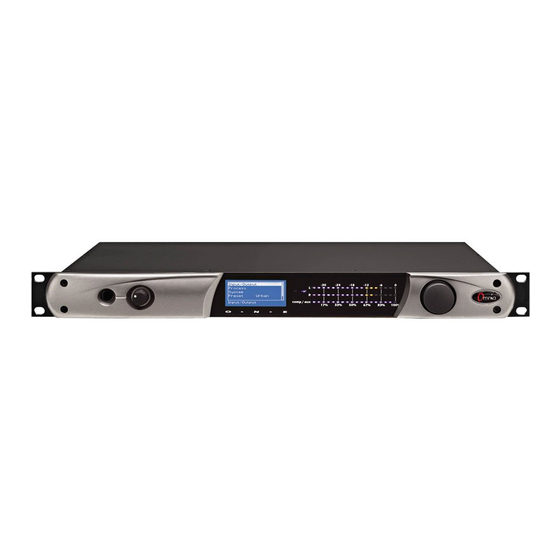
Omnia.ONE
Stereo Audio Processor
Installation and Operation Manual
Revised: June 2013
Applicable to All Software Styles
Software Version 2.6
Omnia ● 1241 Superior Avenue East, Cleveland, Ohio 44114 USA
TEL: +1 216.241.7225 ● FAX: +1 216.241.4103 ● www.omniaaudio.com
Related Manuals for Omnia ONE
Summary of Contents for Omnia ONE
-
Page 1
Omnia.ONE Stereo Audio Processor Installation and Operation Manual Revised: June 2013 Applicable to All Software Styles Software Version 2.6 Omnia ● 1241 Superior Avenue East, Cleveland, Ohio 44114 USA TEL: +1 216.241.7225 ● FAX: +1 216.241.4103 ● www.omniaaudio.com… -
Page 3: President’s Message
It was 1986, in the engineering shop at Z-100, (WHTZ-FM) New York City where our first product was born — The Vigilante FM Limiter. Twenty-one years later and with an incredibly talented team of designers behind it, we offer you the newest baby in our ever-growing family, Omnia.ONE!
-
Page 5: Omnia.one Fm Quick-Start Setup
Omnia.ONE FM Quick-Start Setup We know that you’re probably in a hurry to begin using your new Omnia.ONE FM. If you have technical expertise and previous knowledge of audio processor fundamentals, using this Quick-Start guide will get you up and running as quickly as possible.
-
Page 6
10. Navigate back to the Main Menu, highlight Preset: and click. Rotate the jog wheel to display the preset you would like to start with and click to select it. Go through all of the presets and start with one that sounds best to you. -
Page 7: Omnia.one.sg Quick-Start Setup
Using typical program material, turn up the main clipper drive on your external FM processor temporarily to provide a more steady “worst-case” level at the input of the Omnia ONE.SG. If using a digital output on the external FM processor, set its peak output level to -12.0dBFS if possible. If so, set the Omnia’s input Level control in the Discrete I/O / Input menu to 0.0dB to start.
-
Page 8
In the Discrete I/O / Input submenu, adjust the appropriate input Level control until the peak-reading input bargraph meters are just lighting only the first one or two yellow LEDs. If there is some overshoot in the output of your external FM processor or the link between it and the Omnia ONE.SG, more than the first LED may light. -
Page 9: Omnia.one Am Quick-Start Setup
Main Menu / G/R Metering LCD Display Level Meters Install the Omnia.ONE in the equipment rack using at least two rack screws. If only two screws are used, they MUST be installed in the bottom holes of the rack ears! Connect the audio inputs that are appropriate for your installation.
-
Page 10
12. Navigate back to the Main Menu, highlight Preset: and click. Rotate the jog wheel to display the preset you would like to start with and click to select it. Go through all of the presets and start with one that sounds best to you. -
Page 11: Omnia.one Multicast / Dab / Studio Pro Quick-Start Setup
Main Menu / G/R Metering LCD Display Level Meters Install the Omnia.ONE in the equipment rack using at least two rack screws. If only two screws are used, they MUST be installed in the bottom holes of the rack ears! Connect the audio inputs that are appropriate for your installation.
-
Page 12
Navigate back to the Main Menu, highlight Preset: and click. Rotate the jog wheel to display the preset you would like to start with and click to select it. It is best to go through all of the appropriate presets and start with one that sounds best to you. -
Page 13: Table Of Contents
Omnia.ONE FM Quick-Start Setup ………………. iii Omnia.ONE.SG Quick-Start Setup………………..v Omnia.ONE AM Quick-Start Setup ………………vii Omnia.ONE Multicast / DAB / Studio Pro Quick-Start Setup ……….ix S A F E T Y I N S T R U C T I O N S ………………xv HAZARD / WARNING LABELS ………………..
-
Page 14
Air-Sound Equalization Changes ………………15 Thunder Bass ……………………16 AM Style ……………………..16 Using Omnia.ONE AM with Early PWM Transmitters ……….. 16 The Factory Presets ………………….17 Increasing Density/Loudness ……………….. 18 Adding More Detail — When Loudness Isn’t the Last Word ………. 19 Air-Sound Equalization Changes ……………… -
Page 15
Appendix A: Performance Specifications …………….117 Omnia.ONE FM ……………………117 Omnia.ONE SG ……………………120 Omnia.ONE AM ……………………123 Omnia.ONE Multicast/DAB & Studio Pro…………….. 126 Appendix B: Troubleshooting/Service/Warranty …………..129 Diagnostics and Error Messages………………130 Electrical and mechanical safety note! …………….131 Narrowing down problems………………..131 Obtaining Service …………………..132… -
Page 16
Warranty ……………………..133 Appendix C: Remote Control and Software Update Procedure ……….135 Remote Control ……………………135 Remote ……………………..136 Preset Tab……………………137 Processing Tab ………………….137 In Tab ………………………138 Out Tab ……………………139 IO Tab ……………………..139 Encode Tab (FM Style Only) ………………139 Livewire …………………….. 140 File Transfer …………………… -
Page 17: S A F E T Y
S A F E T Y I N S T R U C T I O N S Read All Instructions. All safety and operating 14. Object and Liquid Entry. Never push objects of any instructions must be read before operating the kind into this product through openings as they may product.
-
Page 18: Hazard / Warning Labels
HAZARD / WARNING LABELS The Exclamation Point symbol, within an equilateral triangle, alerts the user to the presence of important operating and maintenance (servicing) instructions in product literature and instruction manuals. The Lightning Flash With Arrowhead symbol, within an equilateral triangle, alerts the user to the presence of non-insulated dangerous voltages within the product’s enclosure that may be of sufficient magnitude to constitute a risk of electric shock.
-
Page 19: Manual Update Notification
This Directive bans the placing on the European market of new electrical and electronic equipment containing more than agreed levels of lead, cadmium, mercury, hexavalent chromium, polybrominated biphenyl (PBB) and polybrominated diphenyl ether (PBDE) flame retardants. Omnia.ONE FM is in compliance with the EU RoHS Directive.
-
Page 20: Chapter-1: Installation
Omnia.ONE (or any other microcomputer-based equipment). A White Paper by one of our Support Engineers can be found on the Telos Systems website at the URL listed below. It details proper grounding and contains links to some surge suppression products for both the power mains and the often-neglected telephone, Ethernet and ISDN line connections that can (and do) conduct powerful surges into the equipment.
-
Page 21: Installation & Connections
Rack Mounting & Grounding The Omnia.ONE requires one RU (1.75″ [44.45 mm]) of rack space. Rack mount the unit using four rack screws. If only two screws are going to be used, they should be in the bottom holes in the Omnia front panel. No other two-…
-
Page 22: Rear Panel Connections
A Note about Relative Phase: If the relative phase of your installation (including the Omnia.ONE) differs from that of your existing system, your announcers may feel that they sound “weird” in their headphones. If this occurs, then the relative phase of the processor is 180 degrees from what your air talent is used to.
-
Page 23: 19 Khz Sync Output (Bnc) (Active On Fm And Sg Styles Only)
SCA Input (BNC) (Active on FM and SG Styles Only) Any SCA or RDS signal above 53 kHz can be added to the composite outputs of the Omnia.ONE by connecting the signal to the SCA INPUT connector. The SCA signal is mixed in the analog domain directly into both composite outputs.
-
Page 24: Ethernet / Livewire Connection
232 connector of the Omnia and the external modem. Typically this would be 9-pin to 25-pin cable. (External modems traditionally have 25 pin connectors in «DCE» configuration. The Omnia.ONE has a 9 pin in «DTE» configuration, so the standard 9-pin to 25-pin cable will work).
-
Page 25: General Purpose Interface (Gpi) (Db-9F)
This DB9-female connector serves as a four-input, optoisolated interface to the Omnia’s internal GPI functions. Four of the pins are “ground-sink” inputs, one is a bias voltage input, one is a +5V power output, and the remaining three are “ground.” The inputs can be used to dynamically alter the Omnia.ONE’s operation in response to logic transitions on the interface connection.
-
Page 26: Chapter-2: Getting To Know Your Omnia.one
The Omnia.ONE User Interface Now that your Omnia.ONE is rack-mounted, connected to a program audio source, and turned on, you’re ready to learn how to operate it! This chapter covers the Front Panel User Interface, your window into the Omnia.ONE processor.
-
Page 27: Audio I/O Level Display
AGC, Limiter and Clipper sections within the Omnia.ONE. (varies with style) If the “Menu Display” is currently showing on the Omnia.ONE’s LCD screen, press and hold the jog-wheel for two seconds to switch to the processing meter display as shown below.
-
Page 28: Main Menu
The Omnia.ONE menu system has been designed to be intuitive and simple to use. Most operating parameters can be found under one of the menu headings and sub-headings, allowing adjustments to be made quickly and with ease. Rotating the jog-wheel sequentially highlights each menu item in turn. (See “Using the Jog…
-
Page 29: Using The Jog Wheel
Using the Jog Wheel The main user control for the Omnia.ONE is the easy to use jog wheel with its integral push-switch. Using the control is both intuitive and efficient, making it easy to navigate the menu structure of the Omnia.ONE. Processing changes and system adjustments can be quickly made with ease without having to remember multiple controls, their positions, and what they do in each menu.
-
Page 30: User Interface Tutorial — Input Source Selection And Peak Level Setting
(less headroom) is strongly discouraged unless there is another level-control device prior to the Omnia.ONE that will keep the input levels from reaching the maximum digital level of 0 dBFS. During normal operation, you should never see the red “0” segments light.
-
Page 31: An Important Word About Time Delay
We have measured the propagation time delay, the amount of time it takes for the audio signal to travel from the analog input of Omnia.ONE to the output at approximately 7.7ms for the FM Style when using AES/EBU digital I/O, about 9.2ms when using analog I/O. This is enough for a slight voice-character coloration to be audible to the person speaking, but usually not enough to be a problem for talent monitoring off the air.
-
Page 32: Chapter-3: Getting The Sound You Want
The Factory Presets If you go through and listen to all of the included factory presets, you should get a “feel” for them and find one to start with that is close to the sound you are looking for.
-
Page 33: Increasing Density/Loudness
Conversely, if you have the luxury to strive for increased sound quality, we’ve got suggestions for you too! Omnia.ONE FM has been designed to minimize the trade-offs between quality and loudness, and we recommend that before starting the process of cranking it up, try to determine beforehand what sonic characteristics might be lacking.
-
Page 34: Adding More Detail — When Loudness Isn’t The Last Word
Once you have satisfactory results in one area (like overall density) you can then move the focus to the next area that you feel needs more tweaking.
-
Page 35: Thunder Bass
Thunder Bass Omnia.ONE FM has the power to shake the walls with low end! If your source material has it, Omnia.ONE FM can expose that deep bass and do it with muscle! Tailoring Thunder Bass for more dominance is simple, and is done by adjusting the following parameters and in the order listed: 1.
-
Page 36: The Factory Presets
95% may be a good idea, regardless of the presence of the “cliff effect” in your transmitter. The Factory Presets If you go through and listen to all of the included factory presets, you should get a “feel” for them and find one to start with that is close to the sound you are looking for.
-
Page 37: Increasing Density/Loudness
The Omnia.ONE AM is definitely capable of generating moment-to-moment loudness; it has the muscle. It also maintains that famous Omnia clarity sought after by top programmers all over the world. Omnia.ONE AM is designed to minimize the impact of the quality vs. loudness trade-off.
-
Page 38: Adding More Detail — When Loudness Isn’t The Last Word
Once you have satisfactory results in one area (like overall density) you can then move the focus to the next area that you feel needs more tweaking.
-
Page 39: Thunder Bass
Thunder Bass Omnia.ONE AM has the power to shake the walls with low end! If your source material has it, Omnia.ONE AM can expose that deep bass and do it with muscle! Tailoring Thunder Bass for more dominance is simple, and is done by adjusting the following parameters and in the order listed: 1.
-
Page 40: Sensus Technology: Audio Processing
(or too expensive) to do in the past. Running on a platform of the latest high power DSP chips, the Omnia.ONE and our new Sensus technology takes digital dynamics processing into a completely new frontier.
-
Page 41: So… What’s So Smart About Sensus
In other words, what you hear at the output of the Omnia.ONE Multicast will bear no relationship to the audio quality that will be achieved after the audio has passed through the coding process! Need a corollary to this? It’s like trying to taste a pizza while still in the grocery store and staring at the raw ingredients that haven’t been purchased…
-
Page 42: A Word About Density, Clarity, And Intelligibility
“breathing,” “dense,” or “mushy.” It can even induce exaggerated “swish/swirl” artifacts from the codec. Please remember that the core objective of the Omnia.ONE Multicast product is maximum intelligibility at low bitrates and processing that creates heavy density can completely mask that effort. A codec provisioning processor is in quite a different role than a conventional on-air processor.
-
Page 43: Increasing Density/Loudness
Once you have satisfactory results in one area (like overall density) you can then move the focus to the next area that you feel needs more tweaking.
-
Page 44: Equalization (Eq) Changes
Thunder Bass Omnia.ONE Multicast has the power to shake the walls with low end! If your source material has it, Omnia.ONE Multicast can expose that deep bass and do it with muscle! Tailoring Thunder Bass for more dominance is simple, and is done by adjusting the following parameters and in the order listed: 1.
-
Page 45: Coded Audio Considerations
If everything is working properly the vocal quality should not change due to the coding process. If this is noticed, try reducing the Sensus function value by one adjustment click and then re-evaluate.
-
Page 46: Equalization (Eq) Changes
The currently loaded preset is displayed to the right of Preset: on the top line of the Main Menu. You must select a factory preset to get started. Start by listening to each one with typical program material and then start with the one that sounded best to you.
-
Page 47: Bass Enhancement
Bass Enhancement Omnia.ONE Studio Pro has the power to shake the walls with low end! If your source material has it, Omnia.ONE Studio Pro can expose that deep bass and do it with muscle! Tailoring the bass is simple, and is done by adjusting the following parameters and in the order listed: Increase the amount of Bass boost in the Enhance section.
-
Page 48: Chapter-4: Main Menu Selections
100. FM Style Here is a block diagram of the fully digital, DSP based processing stages within the Omnia.ONE FM: The first processing stage is a Wideband AGC (Automatic Gain Control) for overall, automatic “hand on the pot” leveling to keep the following multi-Band stages in their “sweet spot”, followed by the Bass Enhancers (Deep Bass EQ and Phat Bass) and the Crossover (XO), which splits the audio into 4 bands for optimum processing in each of the Bass (L), Midrange (M), Presence (P) and Treble (H) frequency ranges.
-
Page 49: Preset
Preset Omnia.ONE is equipped with a selection of factory presets that can be used to instantly configure the processing for common applications. The currently loaded preset is displayed to the right of Preset: on the top line of the Main Menu.
-
Page 50: Save Preset
» ^ » symbol and click again. The new character appears. Now rotate the knob to select the desired character for it and click to accept. (Note that this inserts a new character before the one selected, and keeps the originally selected character intact as what it was before choosing «^»)
-
Page 51: Rename Preset
<-Exit Click on this option to return to the Main Menu. Adjust Processing This submenu allows changes to be made in any of the Omnia.ONE’s several dozen processing parameters. These adjustments alter the sound and texture of the audio. <-Exit Click on this option to return to the Processing menu.
-
Page 52
AGC Drv (AGC Drive) This control adjusts the amount of drive to the wideband AGC stage. Increasing the drive causes deeper compression to be achieved, and deeper compression allows quieter passages in the input audio to be raised further than if lesser drive (and less compression) was used. -
Page 53
reduction in the lower AGC bands and may cause muddiness with certain program material. A little goes a long way. Warmth This Warm Bass EQ is a shelf boost at 150 Hz. Warmth EQ compensates for program material that is naturally lacking in upper-bass fullness. Be judicious about applying too much, as the resonant frequency of many automobile interiors lies in this frequency range! Also, too much can cause excessive gain reduction in the following 4-Band AGC stage. -
Page 54: Low Band Agc
OV Lim Drv (Overall Limiter Drive) Adjusts the overall amount of drive to all four bands of the multiband Limiter section simultaneously over a + / — 6 dB range. Higher settings will increase density. This can increase loudness but be careful because too much gain reduction in the limiters can lead to a “wall of sound”…
-
Page 55: High Band Agc
Pres Band AGC (Presence Band AGC) See description of settings for Low Band AGC High Band AGC See description of settings for Low Band AGC Low Band Limiter LFLim Drv (Low Frequency Limiter Drive) Adjusts the drive level to the individual Limiter band. Used when you desire more or less density in a specific band.
-
Page 56: Mid Band Limiter
In fact, instead of reducing the output of one of the audio bands in the Final Mixer section, you could instead “dynamically reduce” the level in that band (which also increases density in that band) by lowering the limiter threshold.
-
Page 57
amount of perceived bass in the program material. Be careful! Too much clipping by the Bass Clipper can soften bass ‘punch’. It may also be heard as a “rattling” sound in the bass. Girth Clip When “ON”, this Bass Clipper style is designed to create a phatter effect to low frequencies, and it will help create the illusion of more bass on smaller speakers. -
Page 58
Click on this option to return to the Adjust Processing submenu. Clipper The Clipper is the Omnia.ONE’s final limiting stage. Here is where the Omnia.ONE’s loudness versus quality advantage is most evident! The main clipper is a very powerful algorithm, is highly over-sampled, and is fully anti-aliased. -
Page 59: Input/Output
Failover Time is a feature that when set to a value other than zero (disabled) allows the Omnia.ONE to automatically select another input source if the currently selected one fails. Failover Time is the amount of time that will elapse after the failure of audio on the primary input source before the unit makes the decision to switch to the secondary (failover) input source.
-
Page 60
“Both” is typically selected if it sounds “better” to an announcer (monitoring themselves in headphones using the output of the processing) than “None”. One of the two settings should. The goal is to make the relative phase of the headphone feed more in phase with the announcer’s own bone conduction. -
Page 61
Allows a +/-3dB adjustment of the right analog audio channel gain to correct minor problems in equipment following the Omnia.ONE. The left channel output gain is not affected by this control and is set using the master Analog Level control previously described. -
Page 62
Note: Normally, the “Off” selection under the Pre-emphasis options would not be used in conventional FM transmission applications, but is provided in instances where processing of a flat signal is desired. One example would be when preprocessing prior to a satellite uplink in distributed radio networks. -
Page 63
(STL). In these kinds of installations it is very important that the Omnia.ONE FM is the ONLY device applying the pre-emphasis. All other equipment following the Omnia.ONE FM must have their pre-emphasis disabled for optimum peak modulation control and sound quality. -
Page 64
Stereo Generator SCA Input Gain (Control On Rear Panel) The SCA Input Gain control is an analog trimpot and does not appear in the menu. This trimpot is located just above the SCA Input BNC jack on the rear panel. A small flat-blade screwdriver will be needed to adjust it. -
Page 65
Use this to save your I/O configuration as the system default or save more than one configuration if the unit will be used with different external equipment configurations. These saved configurations can be recalled using the “Load IO Config”… -
Page 66: Administrative
Now rotate the knob to select the desired character for it and click to accept. (Note that this inserts a new character before the one selected, and keeps the originally selected character intact as what it was before choosing «^») When you are finished, simply rotate the knob clockwise with the cursor in “select”…
-
Page 67: Network Configuration
Accepts data in the form of four octets to describe the Ipv4 network address assigned to the Omnia.ONE’s network interface. The entries have the form of: [ octet] . [ octet] . [ octet ] . [ octet] which when entered may appear as a network address such as: 192 .
-
Page 68: Lock Front Panel
Rotating it counter-clockwise will scroll through the numeric characters first, and then through the lower case English alphabet. Once the desired character is found, click to accept that character, rotate the jog wheel one notch clockwise to advance the cursor to the next position and click again to display the editing cursor.
-
Page 69: Sg Style
SG Style The Omnia ONE SG style is designed to accept the output of an external FM audio processor either directly or through a linear digital STL system. It has no audio processing onboard except for a composite clipper stage designed to remove small overshoots from the processed input audio if needed.
-
Page 70
[SB Mode] (Sideband Mode — DSB or SSB) The normal setting for the stereo generator is the DSB setting which provides the full double- sideband, suppressed carrier L-R signal. The special SSB setting provides a single-sideband, suppressed carrier L-R signal that can help reduce multipath and provide increased protection to the baseband spectrum. -
Page 71: Discrete I/O
When set to a value other than zero (disabled) allows the Omnia.ONE to automatically select another input source if the currently selected one fails. Failover Time is the amount of time that will elapse after the failure of audio on the primary input source before the unit makes the decision to switch to the secondary (failover) input source.
-
Page 72
Adjusts the level of the right channel input only over a range of +/- 3.0dB in 0.1dB steps. Invert Inverts the phase of one channel (L inverts only the left channel) (R inverts only the right channel) or BOTH channels. None (the default) passes through both channels normally. -
Page 73
[Mono L+R] — Configures the DSP processing chain to have both the Left and Right internal channels fed from the sum of the Left Channel and Right Channels of the input source selected. Note that this selection is active in all sources selected as Primary and Secondary (Failover) audio sources. -
Page 74
Use this to save your I/O configuration as the system default or save more than one configuration if the unit will be used with different external equipment configurations. These saved configurations can be recalled using the “Load IO Config” option. To save an IO configuration proceed as follows: Highlight “Save IO Config”… -
Page 75: Load Io Config
(Note that this inserts a new character before the one selected, and keeps the originally selected character intact as what it was before choosing «^») When you are finished, simply rotate the knob clockwise with the cursor in “select” mode until the Save button is highlighted and click to save the configuration preset.
-
Page 76: Administrative
Administrative About Presents a dialog displaying the Omnia.ONE software style, firmware release version and front panel software version currently active in the unit. Contrast Adjusts the contrast of the front panel LCD display to optimize it for various viewing angles.
-
Page 77: Lock Front Panel
English alphabet. Once the desired character is found, click to accept that character, rotate the jog wheel one notch clockwise to advance the cursor to the next position and click again to display the editing cursor.
-
Page 78: Am Style
AM Style Here is a block diagram of the fully digital, DSP-based processing stages within the Omnia.ONE AM: The first processing stage is a Wideband AGC (Automatic Gain Control) for overall, automatic “hand on the pot” leveling to keep the following 4-Band stages in their “sweet spot”, followed by the Bass Enhancers (Deep Bass EQ and Phat Bass) and the Crossover (XO), which splits the audio into 4 bands for optimum processing in each of the Bass (L), Midrange (M), Presence (P) and Treble (H) frequency ranges.
-
Page 79: Preset
Preset Omnia.ONE is equipped with a selection of factory presets that can be used to instantly configure the processing for common applications. The currently loaded preset is displayed to the right of Preset: on the top line of the Main Menu.
-
Page 80: Delete Preset
» ^ » symbol and click again. The new character appears. Now rotate the knob to select the desired character for it and click to accept. (Note that this inserts a new character before the one selected, and keeps the originally selected character intact as what it was before choosing «^»)
-
Page 81: Exit
<-Exit Click on this option to return to the Main Menu. Adjust Processing This submenu allows changes to be made in any of the Omnia.ONE’s several dozen processing parameters. These adjustments alter the sound and texture of the audio. <-Exit Click on this option to return to the Main Menu.
-
Page 82
AGC Att (AGC Attack) The attack control adjusts how fast the AGC responds to sudden increases in audio level, and higher numbers equate to faster response times. Faster attack times reduce the transient nature of the input audio, while slower attack times improve it. Extremely slow attack times must be used with caution because allowances must be made in later stages to not overload them during the time when the broadband AGC is adjusting the level downwards. -
Page 83
is unable to reproduce. On systems with larger speakers, the effect of Phat Bass becomes subtler because the extended frequency response of those systems allows the fundamentals of the low notes to be heard, masking the added harmonics contributed by Phat Bass. -
Page 84
Pres Drive Adjusts the amount of gain reduction in the Presence Band AGC. Higher numbers result in more drive and because of the increased compression, a more consistent output from the band. Hi Drive Adjusts the amount of gain reduction in the High Band AGC. Higher numbers result in more drive and because of the increased compression, a more consistent output from the band. -
Page 85
Gt Thresh (Gate Threshold) When the input audio falls below a certain level, the gain control action of the AGC stage is “frozen” by the gate. The level at which this freeze, or hold takes place is controlled by the setting of the Gate Threshold control. Higher numbers cause the gate to activate at higher audio levels. -
Page 86
In fact, instead of reducing the output of one of the audio bands in the Final Mixer section, you could instead “dynamically reduce” the level in that band (which also increases density in that band) by lowering the limiter threshold. -
Page 87
Mid Band Limiter See description of settings for Low Band Limiter Presence Band Limiter See description of settings for Low Band Limiter High Band Limiter See description of settings for Low Band Limiter Bass Clipper The Bass Clipper operates between the output of the Low Band Limiter and the Low Band Mixer, the output of which feeds the main Clipper. -
Page 88
Click on this option to return to the Adjust Processing submenu. Clipper The Clipper is the Omnia.ONE’s final limiting stage. Here is where the Omnia.ONE’s loudness versus quality advantage is most evident! The main clipper is a very powerful algorithm, is highly over-sampled, and is fully anti-aliased. -
Page 89: Input/Output
<-Exit Click on this option to return to the Input/Output menu. Input Src (Input Source) Allows the selection of Analog, AES/EBU (digital) or Livewire as the primary input source to the Omnia.ONE. Fover Time (Failover Time)
-
Page 90
No Channel inversion is performed (factory default) [Both] – Both left and right channel phase is inverted. “Both” is typically selected if it sounds “better” to an announcer (monitoring themselves in headphones using the output of the processing) than “None”. One of the two settings… -
Page 91
XLR male connectors. This control adjusts both the left d right stereo channels simultaneously. Right Trim Allows a +/-3dB adjustment of the right analog audio channel gain to correct minor problems in equipment following the Omnia.ONE. The left channel output gain is not… -
Page 92
Allows a +/-3dB adjustment of the right digital audio channel gain to correct minor left/right balance problems in equipment following the Omnia.ONE. The left channel output gain is not affected by this control and is set using the master AES Level control previously described. -
Page 93
The following spectrograph displays the performance of the 10kHz NRSC-compliant low pass filter: [Tilt EQ] (Tilt Equalization) [Tilt Freq] (Tilt Frequency) Low frequency tilt and equalization controls have been provided after the Omnia.ONE AM’s clipper section in order to compensate for certain design deficiencies in older… -
Page 94
Omnia’s Tilt Equalizer when it is being used on older, less adequate transmitters! Navigate to the Omnia.ONE’s Output Menu, and reduce the output levels to 0dBU on both Left and Right channels. Connect a sine wave Audio Oscillator to the Omnia.ONE AM audio inputs. Set the oscillator to provide a 50 Hz, 0dBu output. -
Page 95
After optimizing the Tilt controls for your particular transmitter, the Tilt adjustment is complete. Normal programming may be applied and the Omnia.ONE’s output levels adjusted for the desired negative and positive modulation. Please see the following oscilloscope photographs of three examples of tilt equalization on the next page. -
Page 96
Use this to save your I/O configuration as the system default or save more than one configuration if the unit will be used with different external equipment configurations. These saved configurations can be recalled using the “Load IO Config” option. To save an IO configuration proceed as follows: Highlight “Save IO Config”… -
Page 97: Administrative
(Note that this inserts a new character before the one selected, and keeps the originally selected character intact as what it was before choosing «^») When you are finished, simply rotate the knob clockwise with the cursor in “select” mode until the Save button is highlighted and click to save the configuration preset.
-
Page 98
Accepts data in the form of four octets to describe the Ipv4 network address assigned to the Omnia.ONE’s network interface. The entries have the form of: [ octet] . [ octet] . [ octet ] . [ octet] which when entered may appear as a network address such as: 192 . -
Page 99: Lock Front Panel
English alphabet. Once the desired character is found, click to accept that character, rotate the jog wheel one notch clockwise to advance the cursor to the next position and click again to display the editing cursor.
-
Page 100: Multicast/Dab Style
Omnia.ONE: 24, 32, 48 and 64 kbps. By starting with one of the factory presets (usually the one named closest to the primary programming and bitrate to be used on the channel the Omnia.ONE Multicast is processing) and then altering it using the controls in the Processing menu, you may change the sound of a preset and then save it with your changes as a user preset for either immediate use or later recall.
-
Page 101: Preset
Preset Omnia.ONE is equipped with a selection of factory presets that can be used to instantly configure the processing for common applications. The currently loaded preset is displayed to the right of Preset: on the top line of the Main Menu.
-
Page 102: Delete Preset
» ^ » symbol and click again. The new character appears. Now rotate the knob to select the desired character for it and click to accept. (Note that this inserts a new character before the one selected, and keeps the originally selected character intact as what it was before choosing «^»)
-
Page 103: Adjust Processing
Adjust Processing This submenu allows changes to be made in any of the Omnia.ONE’s several dozen processing parameters. These adjustments alter the sound and texture of the audio. <-Exit Click on this option to return to the Processing menu. Pre-processing…
-
Page 104
The release control adjusts how fast the AGC recovers from periods of more gain reduction when the input audio levels fall. Faster release times (higher numbers) result in a more dense sound. Even though the Omnia uses program controlled release algorithms, setting the control for extremely fast release times can result in ‘pumping’. -
Page 105
Xover (Crossover) The crossover splits the audio signal into 4 independent bands to enable optimum processing for the bass (L), midrange (M), presence (P) and treble (H) frequency ranges. There are two four-band processing stages that share the same crossover. The crossover points are 180Hz, 1kHz and 3.3kHz plus 6.5kHz for the optional 5 limiter band. -
Page 106
Low Band AGC Attack The attack control adjusts how fast the AGC responds to sudden increases in audio level, and higher numbers equate to faster response times. Faster attack times reduce the transient nature of the input audio, while slower attack times improve it. Extremely slow attack times must be used with caution so as not to allow later stages to be overloaded during the time when the AGC is adjusting the level downwards. -
Page 107
Low Band Limiter LFLim Drv (Low Frequency Limiter Drive) Adjusts the drive level to the individual Limiter band. Used when you desire more or less density in a specific band. These Limiter Drive controls can also be used as secondary dynamic EQ controls after the Drive controls in the AGC Xover. -
Page 108
The drawback is that it can generate intermodulation distortion in the Final Limiter and increase artifacts in the codec employed after the Omnia.ONE Multicast. When both the Girth Clip and Tight Clip settings are both set to “OFF”, the Bass Clipper is effectively bypassed. -
Page 109
Mid Band Adjusts the output level of the mid band limiter into the following Final Limiter stage. Higher numbers result in more midrange but too much mix level can make the following final limiter work unnecessarily hard. Presence Band Adjusts the output level of the presence band limiter into the following Final Limiter stage. Higher numbers result in more presence but too much mix level can make the following final limiter work unnecessarily hard. -
Page 110
Omnia.ONE Multicast offers this feature as a low pass output filter that can be set to one of seven stop band frequencies. Each of the filters possess minimal passband ripple and are phase linear below cutoff. -
Page 111: Input/Output
The Nyquist Theorem states that the maximum frequency that may be applied to a sampled data system is one half the sampling frequency. When signals beyond half the sampling frequency are present, aliasing occurs which causes the appearance of an inverted spectral image of the audio spectrum to be “folded around” the…
-
Page 112
Failover Time is a feature that when set to a value other than zero (disabled) allows the Omnia.ONE to automatically select another input source if the currently selected one fails. Failover Time is the amount of time that will elapse after the failure of audio on the primary input source before the unit makes the decision to switch to the secondary (failover) input source. -
Page 113
“Both” is typically selected if it sounds “better” to an announcer (monitoring themselves in headphones using the output of the processing) than “None”. One of the two settings should. The goal is to make the relative phase of the headphone feed more in phase with the announcer’s own bone conduction. -
Page 114
Allows a +/-3dB adjustment of the right analog audio channel gain to correct minor problems in equipment following the Omnia.ONE. The left channel output gain is not affected by this control and is set using the master Analog Level control previously described. -
Page 115
Use this to save your I/O configuration as the system default or save more than one configuration if the unit will be used with different external equipment configurations. These saved configurations can be recalled using the “Load IO Config” option. To save an IO configuration proceed as follows: Highlight “Save IO Config”… -
Page 116: Administrative
(Note that this inserts a new character before the one selected, and keeps the originally selected character intact as what it was before choosing «^») When you are finished, simply rotate the knob clockwise with the cursor in “select” mode until the Save button is highlighted and click to save the configuration preset.
-
Page 117
Accepts data in the form of four octets to describe the Ipv4 network address assigned to the Omnia.ONE’s network interface. The entries have the form of: [ octet] . [ octet] . [ octet ] . [ octet] which when entered may appear as a network address such as: 192 . -
Page 118: Lock Front Panel
English alphabet. Once the desired character is found, click to accept that character, rotate the jog wheel one notch clockwise to advance the cursor to the next position and click again to display the editing cursor.
-
Page 119: Studio Pro Style
Preset Omnia.ONE is equipped with a selection of factory presets that can be used to instantly configure the processing for common applications. The currently loaded preset is displayed to the right of Preset: on the top line of the Main Menu.
-
Page 120: Adjust Processing
We will discuss the Save Preset, Delete Preset, Rename Preset and <-Exit options first before delving into the details of the Adjust Processing menu. Adjust Processing This submenu allows changes to be made in any of the Omnia.ONE’s several dozen processing parameters. These adjustments alter the sound and texture of the audio. <-Exit Click on this option to return to the Processing menu.
-
Page 121
AGC Att (AGC Attack) The attack control adjusts how fast the AGC responds to sudden increases in audio level, and higher numbers equate to faster response times. Faster attack times reduce the transient nature of the input audio, while slower attack times improve it. Extremely slow attack times must be used with caution because allowances must be made in later stages to not overload them during the time when the broadband AGC is adjusting the level downwards. -
Page 122
with larger speakers, the effect of Phat Bass becomes subtler because the extended frequency response of those systems allows the fundamentals of the low notes to be heard, masking the added harmonics contributed by Phat Bass. Be careful though, too much Phat Bass boost can lead to excessive gain reduction in the lower AGC bands and may cause muddiness with certain program material. -
Page 123
consistent. Be careful though because too much compression can cause the program material to sound less natural and cause low-level noise in the program material to be brought up. OV Lim Drv (Overall Limiter Drive Adjusts the overall amount of drive to all four bands of the multiband Limiter section simultaneously over a + / — 6 dB range. -
Page 124
<-Exit Click on this option to return to the Adjust Processing submenu. Mid Band AGC See description of settings for Low Band AGC Pres Band AGC (Presence Band AGC) See description of settings for Low Band AGC High Band AGC See description of settings for Low Band AGC Low Band Limiter LFLim Drv (Low Frequency Limiter Drive) -
Page 125
Be careful! Too much clipping by the Bass Clipper can soften bass ‘punch’. It may also be heard as a “rattling” sound in the bass or cause additional artifacts in the codec following the Omnia.ONE Studio Pro. Girth Clip When “ON”, this Bass Clipper style is designed to create a phatter effect to low frequencies, and it… -
Page 126
Click on this option to return to the Adjust Processing submenu. Final Limit The Omnia.ONE Studio Pro employs a defeatable final look-ahead limiter to provide absolute precision peak control. This limiter has been designed to minimize processing side-effects like IM distortion, which are usually associated with limiters of this type. -
Page 127: Input/Output
Final Limiter. Ensure that there is enough headroom in the equipment following the Omnia.ONE or reduce the Omnia.ONE’s output level as needed to prevent clipping of the output or overloading the input of the equipment following the Omnia.ONE.
-
Page 128
Failover Time is a feature that when set to a value other than zero (disabled) allows the Omnia.ONE to automatically select another input source if the currently selected one fails. Failover Time is the amount of time that will elapse after the failure of audio on the primary input source before the unit makes the decision to switch to the secondary (failover) input source. -
Page 129
“Both” is typically selected if it sounds “better” to an announcer (monitoring themselves in headphones using the output of the processing) than “None”. One of the two settings should. The goal is to make the relative phase of the headphone feed more in phase with the announcer’s own bone conduction. -
Page 130
Allows a +/-3dB adjustment of the right analog audio channel gain to correct minor problems in equipment following the Omnia.ONE. The left channel output gain is not affected by this control and is set using the master Analog Level control previously described. -
Page 131: Save Io Config
» ^ » symbol and click again. The new character appears. Now rotate the knob to select the desired character for it and click to accept. (Note that this inserts a new character before the one selected, and keeps the originally selected character intact as what it was before choosing «^»)
-
Page 132: Administrative
Click on this option to return to the Main Menu. Administrative About Presents a dialog displaying the Omnia.ONE software style, firmware release version and front panel software version currently active in the unit. Contrast Adjusts the contrast of the front panel LCD display to optimize it for various viewing angles.
-
Page 133
Accepts data in the form of four octets to describe the Ipv4 gateway address assigned to the Omnia.ONE’s network interface. The entries have the form of: [ octet] . [ octet] . [ octet ] . [ octet] which when entered may appear as a network address such as: 192 . -
Page 134: Lock Front Panel
English alphabet. Once the desired character is found, click to accept that character, rotate the jog wheel one notch clockwise to advance the cursor to the next position and click again to display the editing cursor.
-
Page 136: Appendix A: Performance Specifications
Appendix A: Performance Specifications Omnia.ONE FM Note: Discrete I/O measurements have been made in «Bypass» mode (available in the Input/Output menu). FM composite measurements have been made using the «Proof_Perf» preset. General Audio Specifications Frequency Response: Complies with the standard 50 or 75 microsecond pre-emphasis curve within ± 0.50 dB, 30 Hz to 15 kHz.
-
Page 137
Electronically balanced. Input impedance 10k ohms resistive. Maximum Input Level: +22 dBu. Nominal Input Level: +4dBu, which nets a -18dBFS input meter reading on a steady- state signal when the Input Gain control is set to 0.0dB. Program material with a nominal average level (VU reading) of +4dBu will typically produce peak readings on the input meter in the range of -12 dBFS to -6dBFS. -
Page 138
Humidity: 0-95% RH, non-condensing. Dimensions: 19″ wide x 1.75″ high x 16″ deep (48.26cm wide x 13.335 cm high x 40.64 cm deep) including connectors. Unit requires one EIA rack space for mounting. Shipping Weight: 12 lbs. / 5.5 kg StudioHub… -
Page 139: Omnia.one Sg
Omnia.ONE SG General Audio Specifications Frequency Response: Complies with the standard 50 or 75 microsecond pre-emphasis curve within ± 0.50 dB, 30 Hz to 15 kHz. The analog left/right outputs and AES/EBU Digital outputs can be configured for flat or pre- emphasized output.
-
Page 140
A/D Conversion: Crystal Semiconductor CS5361, 24 bit 128x over-sampled delta sigma converter with linear-phase anti-aliasing filter. Pre-ADC anti-alias filter, with high-pass filter at <10 Hz. Connectors: Two, EMI-suppressed XLR-female. Pin 1 chassis ground, Pin 2 «Hot». Analog Audio Output: Left/Right Stereo. Electronically balanced. Output Impedance 20 ohms. -
Page 141
Humidity: 0-95% RH, non-condensing. Dimensions: 19″ wide x 1.75″ high x 16″ deep (48.26cm wide x 13.335 cm high x 40.64 cm deep) including connectors. Unit requires one EIA rack space for mounting. Shipping Weight: 12 lbs. / 5.5 kg StudioHub… -
Page 142: Omnia.one Am
Omnia.ONE AM Note: Discrete I/O measurements have been made in «Bypass» mode (available in the Input/Output menu). Note: All measurements made with the supplied “FACT_TEST” preset, which is available in the Preset Submenu. System Frequency Response Complies with the NRSC emphasis curve within ± 0.50 dB, 30 Hz to 10 kHz.
-
Page 143
Operating Temperature: 32 to 122 deg. F / 0 to 50 deg. C for all operating voltage ranges. Humidity: 0-95% RH, non-condensing. Dimensions: 19″ wide x 1.75″ high x 16″ deep (48.26cm wide x 13.335 cm high x 40.64 cm deep) including connectors. Unit requires one EIA rack space for mounting. -
Page 144
Shipping Weight: 12 lbs. / 5.5 kg StudioHub is a registered trademark of Radio Systems. Telos/Omnia Research and Development is constantly working to improve the quality of our products. Actual specifications are subject to change or improvement without notice. -
Page 145: Omnia.one Multicast/Dab & Studio Pro
Omnia.ONE Multicast/DAB & Studio Pro As of February 2009 – Version 2.2 Multicast, DAB or Studio Pro Software Note: All measurements made using «Bypass» mode, which is available in the Input/Output menu. General Audio Specifications Frequency Response: ± 0.50 dB, 20 Hz to 20 kHz with high pass filter disabled.
-
Page 146
Humidity: 0-95% RH, non-condensing. Dimensions: 19″ wide x 1.75″ high x 16″ deep (48.26cm wide x 13.335 cm high x 40.64 cm deep) including connectors. Unit requires one EIA rack space for mounting. Shipping Weight: 12 lbs. / 5.5 kg StudioHub… -
Page 148: Appendix B: Troubleshooting/Service/Warranty
RS-232 port, as well as viewing of any error messages that may be encountered. This chapter explains the various boot up and error messages that may be encountered while troubleshooting the unit. We’ll cover some basic troubleshooting techniques for isolating possible Omnia.ONE problems in the field, and also how to obtain help or repair service from Omnia.
-
Page 149: Diagnostics And Error Messages
Diagnostics and Error Messages To run a system diagnostics check of the Omnia.ONE unit that can be used by Telos/Omnia Customer Support personnel in case of difficulty with the unit, click on the “Factory Diagnostics” link option in the Utilities section at the bottom of the Configuration screen: A report similar to the below will be generated.
-
Page 150: Electrical And Mechanical Safety Note
If the signal is dead at all three, then this points to a digital audio problem after the dynamic processing DSP chips. If one of the output sections is not operating, then it can be localized to that specific section.
-
Page 151: Obtaining Service
Obtaining Service • Before contacting Omnia Customer Support, please have the serial number of the unit (located on a barcode sticker on the rear panel in this format: 0220WXXXX) and a description of the symptoms/problems ready for the technician. • All units being returned to for service MUST have a Return Authorization (RA) number assigned to them first.
-
Page 152: Warranty
Warranty This Warranty covers «the Products,» which are defined as the various audio equipment, parts, software and accessories manufactured, sold and/or distributed by TLS Corp., d/b/a Omnia (hereinafter «Omnia»). With the exception of software-only items, the Products are warranted to be free from defects in material and workmanship for a period of two years from the date of receipt by the end-user.
-
Page 154: Appendix C: Remote Control And Software Update Procedure
The above screenshot shows the Processing screen of the Omnia.ONE’s built-in remote control applet. NOTE: The FM software style will be used to illustrate the Omnia.ONE Remote Control screens in this chapter. Some screens and their available controls will differ slightly in the other styles.
-
Page 155: Remote
Once Java is installed on your computer, using a Web browser, connect to the IP address of your Omnia.ONE as follows: (see Network Configuration on Page 48 if you need to enter the Network parameters into the Omnia.ONE) Open a standard Web Browser on your computer and connect to the Omnia.ONE by entering:…
-
Page 156: Preset Tab
Omnia.ONE’s front panel. To refresh the front panel preset name, simply click the Omnia.ONE’s jog wheel to enter one of the menus and then click “<-Exit”. (Or enter the Preset menu, rotate the Jog Wheel to the right and select “Cancel*”…
-
Page 157: In Tab
To change the “radio button” settings, simply click once on the button or name of the desired setting and release. In Tab Clicking on the “In” tab will display all of the controls for the Omnia.ONE’s Input menu in the main applet screen. Adjustment of the controls works the same way as described above…
-
Page 158: Out Tab
To enter the IO Configuration menu, click on the “IO” tab. Here you can select a previously saved IO Configuration from the Omnia.ONE’s memory, save your changes to an existing IO configuration, save your IO settings as a new IO Configuration or delete an existing IO Configuration.
-
Page 159: Livewire
Livewire output stream mode is selected. The Livewire output can also be disabled here. In the “Input to Omnia.ONE” section, the channel from your Livewire system to be input to the Omnia.ONE is selected. The Mode: dropdown box should normally be left at the default setting: “From source”.
-
Page 160: File Transfer
Presets are saved as small, text-based files with the “.opr” extension. To upload a previously saved user preset to the Omnia.ONE, use the file entry box (or the browse button) to enter the path to the preset file name to be uploaded and press the “Upload” button.
-
Page 161: I/O Configuration File Transfer
So, after uploading a preset to the unit from the remote, simply save any preset as a new name, rename a preset or delete a preset using the front panel jog wheel and the uploaded preset should then show up in the front panel’s preset list.
-
Page 162: Software Update Procedure
This is a safeguard against loss of power or other interruption during the update. In this event, the Omnia.ONE should still boot into the active bank containing the “old” software (but it is best to avoid interruptions in any case).
-
Page 163
1, double-click it so that it appears in the “Update File:” box, then click the “Update” button. The file will now be uploaded to the Omnia.ONE. This may take up to 5 minutes. A progress bar may or may not appear, depending on the browser being used but once the file is successfully uploaded to the Omnia.ONE, the following “Update Initiated”… -
Page 164
Scroll down the Configuration page to find the “Select Software Bank:” section: In this example, the new software has been uploaded to Bank 1. You will notice that the previous software (Bank 0 in this case) is still selected and running. You can choose to change to the other bank to activate the new software or keep running the current software and reboot later. -
Page 166: Appendix D: Gpi Using The «Interface» Connector (New In Version 2.6)
Appendix D: GPI using the “INTERFACE” connector (New in Version 2.6) Pin 1: +5VDC Out Pin 2: In COM+ Pin 3: IN 1: Trigger input #1 Pin 4: IN 2: Trigger input #2 Pin 5: IN 3: Trigger input #3 Pin 6: IN 4: Trigger input #4 Pins 7,8,9: GND For operation, a voltage must be applied to voltage input on pin 2.
-
Page 167
The Omnia ONE offers the ability to control several functions by means of trigger events (a trigger event is either a physical contact closure or a virtual LiveWire GPIO event). Currently, presets may be selected, the primary and secondary input sources may be selected, and the failover state may be set (forcing a switch to the secondary input) or cleared (forcing a restore to primary input). -
Page 168
Each of the five pins acts independently of the others. Each pin can have one preset assigned to a rising edge on the pin and one preset assigned to a falling edge (or «no action» may be selected for either or both edges). -
Page 169
GPO 3: — PRI <src> — Select the given source, <src>, as the primary input source. <src> must be one of: ANA (for analog), AES (for AES/EBU), or LWR (for LiveWire). — SEC <src> — Select the given source, <src>, as the secondary input source that will be used in case of failover.
- Manuals
- Brands
- Omnia Manuals
- Computer Hardware
- ONE FM
Manuals and User Guides for Omnia ONE FM. We have 2 Omnia ONE FM manuals available for free PDF download: Installation And Operation Manual
-
#1
да простят меня гении этого форума за то, что наверное повторимся в цатый раз. НО! Приглашаю в эту тему тех, кто пользуется Omnia ONE FM и делиться конкретными настройками и пресетами. Не умничайте плизззззз….. просто напишите какой у вас пресет и что вы настраивали в ручную???? какой эффект получили????
-
#3
Мы у себя используем CGBigCHR оттуда. Вроде нормульный пресет ! Единственное частотно дорулил немного в mixer после мультибэнда, а так жмет прилично.
Кстати ! У нас из 30 приборов один закинут полностью. Слетела прошивка. Случаем никто не знает как её залить в чистую омнию ?
-
#4
Мы у себя используем CGBigCHR
Хороший пресет для максимальной громкости при минимальных разборках со связьнадзором
Тоже используем. Баску только добавили немного после мультибэнда (пожирнее).
Ну дык к продавцу надо его послать и пусть парится
-
#5
Хороший пресет для максимальной громкости при минимальных разборках со связьнадзором
Тоже используем. Баску только добавили немного после мультибэнда (пожирнее).
А я наоборот немного придушил басок !
Чет он по default мой саб в тестовом комплекте выносит нафик.
ioneer_smoke:
-
#6
CGBigCHR тоже этим пресетом пользуемся. особо честно говоря о побаиваюсь что то ковырять…..
-
#7
CGBigCHR тоже этим пресетом пользуемся. особо честно говоря о побаиваюсь что то ковырять…..
Не боись! Можно не залазить в многополосник, а поэксперементировать с mixer на выходе.
Хотя… если все устраивает — зачем что-то менять ?!
PS: Если будут вопросы по Omnia One — задавайте !!!
rankster2:
Последнее редактирование: 9 Ноя 2009
-
#8
Подскажите пожалуйста, каким плеером, кроме iPlay, можно воспроизвести поток Livewire?
-
#11
во я лох!!!! прастите….забыл совсем!!! пароль » 123456″
-
#12
а какой у вас уровень входного сигнала?
-
#13
А я наоборот немного придушил басок !
Чет он по default мой саб в тестовом комплекте выносит нафик.
ioneer_smoke:
не по уровню, по окраске :acute:
-
#14
не по уровню, по окраске :acute:
Дык а я про что ? Окрас ! :gamer2:
-
#15
а какой у вас уровень входного сигнала?
До первых желтых светодиодов включительно.
Т.е. входные пики в районе — 12 дБ
ИМХО оптимально тогда звучит.
Последнее редактирование: 4 Мар 2010
-
#17
Простите ,а можно еще раз залить ? По старой ссылке файла нет((
Спасибо
файл опять удален (((
-
#18
прошу прощения….файл утерян. Заново залить никуда не могу по причине отсутствия. Попробую связаться с теми кто мне его дал.
-
#19
прошу помощи!!!! не могу разобраться с уровнями! моя ася — 493921844
-
#20
привет друзья. Всё ковыряюсь с Омнией…пытаюсь громкости в эфире повысить. пока толь эксперименты…
Такой вопрос — А вы обновляли процессор???(Confirm Firmware Update). Надо его обновлять или нет??
Кстати. Нашол тут ту самую маленькую инструкцию по запуску..правда распечатанную. Отсканированная она тут :
http://rghost.ru/4251079
-
#21
Скажите, пожалуйста, можно ли использовать FM процессор Omnia ONE FM дома, просто для записи голоса, будет ли большая задержка? Кто-то пробовал? 
-
#22
Други, кто-нить пользует Omnia.AX(софт)
если не трудно , на прессеты б посмотреть, кто-как рулит?
выложите плиз.:umnik2:
AP!
Последнее редактирование: 14 Фев 2011
-
#24
Скажите, пожалуйста, можно ли использовать FM процессор Omnia ONE FM дома, просто для записи голоса, будет ли большая задержка? Кто-то пробовал?
Можно ли возить ребенка в школу на автокране? Конечно да. Тоже ведь машина)))))
Если серьезно то в принципе то этот прибор имеет и компрессор, и лимитер, и эквалайзер и тп…конечно можно….
А вот про задержку вопрос непонятен…о какой задержке речь?
-
#25
Я послушал процессоры Omnia One и Omnia 6 … может их не настроили… а может это просто такой «фирменный звук»… но тихие песни Omnia как-то плохо вытягивает… Не лучше использовать всё-таки процессоры Orban? В интернете много статей на эту тему…
Может кто-то реально может сравнить две фирмы Omnia и Orban? Есть ли настоящие специалисты, которые могут оценить эти процессоры?
-
#26
radioradioradioradio,
Лучше или не лучше решать всегда конечному пользователю. Со слов и советов Вы все равно до конца не определитесь. Ибо один инженер больше работал с оптимодом, другой с омнией. Могу только выразить ИМХО:
1. Оба прибора (если говорить о omnia 6 и Optimod 85008600) содержат в себе одинаковые функции (автогейн, лимитер, лимитер клипов, эквалайзер, стереоэнхансер ну и тд). Оба имеют функцию генерирования комплексного сигнала (а чего еще надо от FM!! процессора) ). Следовательно выбирайте просто по удобству управления приборами. Хотя и тут…подключились по сети и через браузер все настраивается. Разница конечно в цене есть Омния почти 600 килорублей))
2. Если хотите бу прибор найти, то легче найти оптимод. Но конечно не 8500, а 8300 очень даже часто продается. Можно смело покупать настраивать и он будет работать (если конечно купите исправный).
Так что сравнить их достаточно сложно. Кому то будет удобней орбан, кому то омниа, но уровень приборов все равно примерно равен…это два лидера в этой сфере….Зайдите на любой передающий в москве и кроме этих фирм среди fm процессоров ничего другого нет))…причем например на ОКТОДЕ примерно 5050 орбан и омния))))
-
#27
Может у кого есть инструкця на русском Omnia ONE FM 2.0 Скиньте на [email protected] mail.ru Заранее блогодарен.
-
#28
Ребята, подскажите кто где покупал Omnia One FM, и почем?
Можно в личку.
Нужно покупать, цены везде разные, кому доверять незнаю, на дигитоне покупать?
офф: напишите плиз в личку, лучше она чем ДБМакс? или всетакие стоит всять его но подороже?
upd: кто-нибудь сравнивал Омнию с BW Broadcast? Что скажите, нас уламывают на BW.
Последнее редактирование: 18 Мар 2011
-
#29
офф: напишите плиз в личку, лучше она чем ДБМакс? или всетакие стоит всять его но подороже?
если речь идет о tc.electronic dbmax то сравнение не может быть коректным. Главное отличие омнии это наличие встроенного фммодулятора…омния предназначена для обработки сигнала и !!!! преобразования его в композитный сигнал для передатчика. Но в принципе никто не мешает поставить вместо нее дбмакс и загонять сигнал в передатчик по аесу например…но, повторюсь сравнение не корректно на мой взгляд.
-
#30
Люди, подскажите плиз! Никак не могу настроить этот чудо аппарат. Или очень тихо или засер идет. Я сам далековат от этого. Если несложно, дайте настройки подробные плиз!
![]()
Omnia.ONE
Stereo Audio Processor
Installation and Operation Manual
Revised: June 2013
Applicable to All Software Styles Software Version 2.6
Omnia ● 1241 Superior Avenue East, Cleveland, Ohio 44114 USA TEL: +1 216.241.7225 ● FAX: +1 216.241.4103 ● www.omniaaudio.com

Welcome to Omnia.ONE!
What’s New?
New in software version 2.6 (for the FM style only) is an optional fifth limiter band! The High Band AGC output on the FM style now feeds an optional 6.5kHz crossover and a Super-High Band limiter. There is also some new Livewire-based GPIO functionality.
Also new is the SG style. The SG is a stand-alone FM stereo generator (no processing). It is equipped with a built-in composite clipper and features a single-sideband option.
President’s Message:
I wish to offer my sincere gratitude on behalf of our company and welcome you to Omnia.ONE!
This is our next step in the never-ending quest to build the best signal processor in the world. Considerably more powerful than what its small package implies, Omnia.ONE possesses new hardware and algorithm capabilities that even exceed its predecessors. It is also the first audio processor to incorporate LiveWire connectivity, enabling linear audio over dedicated networks. It’s the hottest ‘interconnect’ technology in the professional audio industry today.
Broadcasters require a lot of flexibility in an audio processor because transmission systems exist in many different forms. The processor you choose must have the tools to meet those needs. Special firmware inside Omnia.ONE allows it to meet the challenges of FM, AM, HD Radio, DAB, DRM, FMing, Podcasting, Netcasting, Satcasting, and any other form of ‘casting’ you can think of. There’s plenty of power inside its little 1U frame, so don’t let the size fool you!
It was 1986, in the engineering shop at Z-100, (WHTZ-FM) New York City where our first product was born — The Vigilante FM Limiter. Twenty-one years later and with an incredibly talented team of designers behind it, we offer you the newest baby in our ever-growing family, Omnia.ONE!
Speaking of the team, I wish to offer a sincere and heart-felt thank you to: Rob Dye, Bill Mohat, Cornelius Gould, Ed Zmuginsky, Mark Manolio, Ted Alexander, David Jablonski,, Betty Ferrell, Marty Greenberg, Steve Kiffmeyer, Denny Sanders, Marty Sacks, Mike Dosch, Kirk Harnack, Mike Uhl, Jim “Clemenza” Armstrong, Marc Johnson, Milos Nemcik, Ken Skok and a host of others (as you can see, it’s not just “Frank” anymore!). It’s a great team of people who always maintain one goal in their minds…keep raising the bar!
Steve Church, my partner in crime and founder of Telos, first introduced DSP technology to broadcasting in 1985. Our team of DSP gurus is the finest in the audio industry. Our own specialized DSP ingenuity has been tremendously beneficial to Omnia’s development.
You have in your possession an incredible audio processor. Also, you have the full support of our entire organization standing behind the product. If you have feedback, or even a new idea, we’re here to listen! Customers, like you, offer us valuable feedback. After all, it’s feedback like yours that helped us introduce the original Omnia.FM, and then take the industry by storm. Our quest today, just as it has been all along, is to continue to be the audio processing brand leader.
To borrow a phrase from my old stomping grounds, Z-100 in New York City, Omnia went from worst to first in the minds and ears of radio broadcasters. We are honored, equally humbled to say the least, and grateful to you, our customers, for helping us make that happen! Omnia processors have been installed by tens of thousands of broadcasters throughout the world, and I am overwhelmed when I look at the list of our end-users. So, it’s to you, our loyal customers and friends, that I say Thank You!
To Great Sounding Audio…the World over!
Frank Foti, President, Omnia Audio
i
ii
Omnia.ONE FM Quick-Start Setup
We know that you’re probably in a hurry to begin using your new Omnia.ONE FM. If you have technical expertise and previous knowledge of audio processor fundamentals, using this Quick-Start guide will get you up and running as quickly as possible. Please refer to the full User Manual for additional installation and setup information.
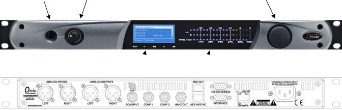
The following illustrations show the location of the various controls and connectors associated with the installation:
|
Headphone Jack Headphone Level Control |
Jog Wheel |
|
Main Menu / G/R Metering LCD Display |
Level Meters |
1.Install the Omnia.ONE in the equipment rack using at least two rack screws. If only two screws are used, they MUST be installed in the bottom holes of the rack ears!
2.Connect the audio inputs that are appropriate for your installation. The Omnia.ONE accepts balanced line-level analog audio via the XLR connectors, AES/EBU digital via the bottom RJ-45 jack (using the “StudioHub” standard pinout) or Livewire.
NOTE: Livewire audio I/O is only to be used if you have an existing Axia or other Livewire system. Otherwise, the Livewire Ethernet jack can be used to remote control the Omnia.ONE via its built-in webpage interface. See Appendix C in the full User Manual for details.
3.Connect the audio outputs in a manner that is appropriate for your installation. We suggest using the composite MPX BNC outputs (and therefore the Omnia’s built-in MPX stereo generator) if at all possible for best performance.
4.Connect AC power to the unit (there is no power switch!)
5.Navigate to the Input/Output / Meter Select setting and select Input.
6.Navigate to the Input/Output / Input / Input Src setting and select the Analog, AES/EBU or Livewire input as appropriate for your installation. If your audio source is active, you should now see meter activity on the LED bargraph meters.
7.While driving the inputs with typical program material at normal operating level, navigate back up to the Input/Output / Input menu (by highlighting and clicking on the “<-EXIT” option) and adjust the appropriate input Level control until the peak-reading input bargraph meters are peaking up to at least –15 and up to –12 dBFS or a little higher.
8.Navigate to the Input/Output / Output / FM Options submenu and ensure that the Pre-Emphasis, De-emphasis and BS-412 settings are correct for your system and your location. If you will not be using the Omnia’s built-in stereo generator, it is very important to ensure that the Omnia is the only device providing the FM pre-emphasis (PreEmphasis ON and De-Emphasis OFF) and that any link between the Omnia’s output and the input to the FM exciter is fully linear with no codecs. If this is not possible, the Omnia must be located at the transmitter site, driving the FM exciter directly.
iii
9.If you are using the Omnia’s built-in stereo generator, navigate to the Input/Output / Stereo Generator menu and adjust the appropriate composite output level control (Comp #1 or Comp #2) for 100% modulation on your station’s modulation monitor. Similarly, adjust the Pilot Lvl control so that the 19kHz stereo pilot injection level indicates between 8 and 10 percent as shown on your station’s stereo modulation monitor. If your modulation monitor does not show pilot injection but you are certain that the total modulation is correct at 100%, simply set the Pilot Lvl control to 9.0%.
If you are using the AES/EBU output to feed pre-emphasized audio to your linear STL or digital exciter, navigate instead to the Input/Output / Output menu and adjust the appropriate output level control for the equipment that follows the Omnia.ONE. Ensure that any limiters, clippers and/or pre-emphasis in the exciter/transmitter are defeated.
10.Navigate back to the Main Menu, highlight Preset: and click. Rotate the jog wheel to display the preset you would like to start with and click to select it. Go through all of the presets and start with one that sounds best to you.
11.We suggest that each time you try a new factory preset, you adjust the Clip Drive in the Processing / Adjust Processing / Clipper menu as follows: Starting with the default setting for a preset, adjust it down in 0.5 dB steps until the loudness just drops below the desired level and then bring it up slightly from there. This should be the optimum setting for your station and market. With most presets, there should be room to turn it up a bit as well if a bit more loudness is needed. Turn it up just enough to achieve the desired loudness level. If you have to turn it up too much, to the point where distortion becomes obtrusive, it would probably be best to start with a more aggressive preset.
The Omnia.ONE Quick-Start Setup is now complete. For more detailed installation and operating instructions (including details about every control function) and to learn about some of the features that make the Omnia.ONE unique, please refer to the latest version of the full Omnia.ONE user manual available on the Omnia website here:
http://omniaaudio.com/manuals
iv

Omnia.ONE.SG Quick-Start Setup
We know that you’re probably in a hurry to begin using your new Omnia.ONE.SG. If you have technical expertise and previous knowledge of stereo generator fundamentals, using this guide will get you up and running as quickly as possible. Please refer to the full User Manual for additional installation and setup information.
The following illustrations show the location of the various controls and connectors associated with the installation:
|
Headphone Jack Headphone Level Control |
Jog Wheel |
|
Main Menu / G/R Metering LCD Display |
Level Meters |
1.Installation: Install the Omnia.ONE.SG in the equipment rack using at least two rack screws. If only two screws are used, they MUST be installed in the bottom holes of the rack ears!
2.Connect the audio inputs that are appropriate for your installation. These should originate from an external FM audio processor and ideally should be pre-emphasized and fully band limited to 16kHz.
3.Connect the Omnia’s composite MPX BNC output(s) as appropriate for your installation to your FM exciter’s baseband composite MPX input or composite STL transmitter.
4.Connect AC power to the unit (there is no power switch!)
5.Navigate to the Discrete I/O / Meter Select setting and select Input.
6.Navigate to the Discrete I/O / Input / Input Src setting and select the Analog, AES/EBU or Livewire input as appropriate for your installation. If your audio source is active, you should now see meter activity on the LED bargraph meters.
Input Calibration: The Omnia ONE.SG is designed to accept pre-processed audio from an external FM audio processor. Ideally, this audio should be pre-emphasized and sourced only through a lossless link using Livewire or AES/EBU. Analog L/R XLR input can also be accepted. Since the Omnia ONE.SG includes a composite clipper, it is very important to calibrate the input level properly so that when the Composite Clip Drive control is set to 0.0, no composite clipping is taking place.
7.Using typical program material, turn up the main clipper drive on your external FM processor temporarily to provide a more steady “worst-case” level at the input of the Omnia ONE.SG. If using a digital output on the external FM processor, set its peak output level to -12.0dBFS if possible. If so, set the Omnia’s input Level control in the Discrete I/O / Input menu to 0.0dB to start.
NOTE: The Omnia ONE SG’s input meters are specially calibrated with higher resolution above -12dBFS for easy and precise input level calibration. The first yellow LED comes on at -12.1dBFS, the second at -11.9dBFS and subsequent ones every 0.2dB above that. The composite clip point (with 0.0dB drive setting) is -12.0dBFS.
v
8.In the Discrete I/O / Input submenu, adjust the appropriate input Level control until the peak-reading input bargraph meters are just lighting only the first one or two yellow LEDs. If there is some overshoot in the output of your external FM processor or the link between it and the Omnia ONE.SG, more than the first LED may light. This should be OK as long as there is not more than a dB or so of overshoot. If there is more overshoot than that, you may need to lower the input level a bit. Be sure in any case that the red “0”dBFS LED’s never light.
9.Ideally, the de-emphasis in the output of your external FM processor should be defeated so that the Omnia ONE.SG is receiving a pre-emphasized, 16kHz band-limited signal. If not, you can turn pre-emphasis and low-pass filtering on. Navigate to the Stereo Generator / Adjust SG submenu and ensure that the Emph Std (50us or 75us), PreEmph (OFF or ON) and Input LPF (OFF or ON) settings are correct for your system and your location.
10.Here in the Stereo Generator / Adjust SG submenu, navigate down to the Comp #1 or Comp #2 controls and adjust the appropriate one for 100% modulation on your station’s modulation monitor. Similarly, adjust the Pilot Lvl control so that the 19kHz stereo pilot injection level indicates between 8 and 10 percent as shown on your station’s stereo modulation monitor. If your modulation monitor does not show pilot injection but you are certain that the total modulation is correct at 100%, simply set the Pilot Lvl control to 9.0%.
11.To save your settings as an SG Config preset, navigate to the Save SG Config setting in the Stereo Generator menu, click on “Name”, enter a preset name using the jog wheel, turn the jog wheel one more click clockwise and click on “Save”. Similarly, I/O configuration presets can also be saved from the Discrete I/O menu.
12.Remember to return your external FM processor’s main clipper drive control to its previous level.
NOTE: To engage the special single-sideband mode available in the Omnia ONE .SG, navigate to the Stereo Generator / Adjust SG submenu and set the SB Mode control to “SSB”. No other adjustments should be needed.
The Omnia.ONE Quick-Start Setup is now complete. For more detailed installation and operating instructions (including details about every control function) and to learn about some of the features that make the Omnia.ONE unique, please refer to the latest version of the full Omnia.ONE user manual available on the Omnia website here:
http://omniaaudio.com/manuals
vi

Omnia.ONE AM Quick-Start Setup
We know that you’re probably in a hurry to begin using your new Omnia.ONE. If you have technical expertise and previous knowledge of audio processor fundamentals, using this Quick-Start guide will get you up and running as quickly as possible. Please refer to the full User Manual for additional installation and setup information.
The following illustrations show the location of the various controls and connectors associated with the installation:
|
Headphone Jack Headphone Level Control |
Jog Wheel |
|
Main Menu / G/R Metering LCD Display |
Level Meters |
1.Install the Omnia.ONE in the equipment rack using at least two rack screws. If only two screws are used, they MUST be installed in the bottom holes of the rack ears!
2.Connect the audio inputs that are appropriate for your installation. The Omnia.ONE accepts balanced line-level analog audio via the XLR connectors, AES/EBU digital via the bottom RJ-45 jack (using the “StudioHub” standard pinout) or Livewire.
NOTE: Livewire audio I/O is only to be used if you have an existing Axia or other Livewire system. Otherwise, the Livewire Ethernet jack can be used to remote control the Omnia.ONE via its built-in webpage interface. See Appendix C in the full User Manual for details.
3.Connect the audio outputs in a manner that is appropriate for your installation. Normally this will be mono balanced analog output to your AM transmitter using either the LEFT or RIGHT output XLR. If you have 2 transmitters, you can use one output for each transmitter and thus have separate level adjustments for each.
4.Connect AC power to the unit (there is no power switch!)
5.Navigate to the Input/Output / Meter Select setting and select Input.
6.Navigate to the Input/Output / Input / Input Src setting and select the Analog, AES/EBU or Livewire input as appropriate for your installation. If your audio source is active, you should now see meter activity on the LED bargraph meters.
7.If you will be running in mono, navigate to the Input/Output / Input / Mono Mode and select the desired mode. Mono L will feed the left channel input’s audio to both output channels, Mono R the same for the right channel input. Mono L+R will sum the left & right inputs and feed the sum to both outputs.
8.While driving the input with typical program material at normal operating level, navigate to the Input/Output / Input menu and adjust the appropriate input Level control until the peak-reading input bargraph meters are peaking up to at least –15 and up to –12 dBFS or a little higher.
vii
9. Navigate to the Input/Output / Output / AM Options submenu and ensure that the Output Polarities, LPF Frequency, Asym Mod and Tilt (normally only used for older plate-modulated transmitters) adjustments are correct for your system and your location. If you will be using asymmetrical modulation to increase your positive modulation above 100%, ensure that when the Asym Mod control is turned up, only the positive modulation peaks are increasing, not the negative peaks. If you find the opposite is true, select Invert for the appropriate output in the menu above.
NOTE: To help make setting modulation levels and positive peaks easier, temporarily set the Processing / Adjust Processing / Clipper / Clip Drive control to a high setting (such as 3.0dB).
10.Navigate to the Input/Output / Output menu and adjust the appropriate control so that the output level is correct for the equipment that follows the Omnia.ONE. Typically this will be the modulation level of your AM transmitter. Ensure that the negative peaks never hit full-cutoff (100%) and then, if desired, increase the asym mod control until positive peak modulation is between 120-125%.
11.Remember to return the Clip Drive control to its previous level.
12.Navigate back to the Main Menu, highlight Preset: and click. Rotate the jog wheel to display the preset you would like to start with and click to select it. Go through all of the presets and start with one that sounds best to you.
The Omnia.ONE Quick-Start Setup is now complete. For more detailed installation and operating instructions (including details about every control function) and to learn about some of the features that make the Omnia.ONE unique, please refer to the latest version of the full Omnia.ONE user manual available on the Omnia website here:
http://omniaaudio.com/manuals
viii
![]()
Omnia.ONE Multicast / DAB / Studio Pro
Quick-Start Setup
We know that you’re probably in a hurry to begin using your new Omnia.ONE. If you have technical expertise and previous knowledge of audio processor fundamentals, using this Quick-Start guide will get you up and running as quickly as possible. Please refer to the full User Manual for additional installation and setup information.
The following illustrations show the location of the various controls and connectors associated with the installation:
|
Headphone Jack Headphone Level Control |
Jog Wheel |
|
Main Menu / G/R Metering LCD Display |
Level Meters |
1.Install the Omnia.ONE in the equipment rack using at least two rack screws. If only two screws are used, they MUST be installed in the bottom holes of the rack ears!
2.Connect the audio inputs that are appropriate for your installation. The Omnia.ONE accepts balanced line-level analog audio via the XLR connectors, AES/EBU digital via the bottom RJ-45 jack (using the “StudioHub” standard pinout) or Livewire.
NOTE: Livewire audio I/O is only to be used if you have an existing Axia or other Livewire system. Otherwise, the Livewire Ethernet jack can be used to remote control the Omnia.ONE via its built-in webpage interface. See Appendix C in the full User Manual for details.
3.Connect the audio outputs in a manner that is appropriate for your installation. Choices are balanced line-level analog audio via the XLR connectors, AES/EBU digital via the top RJ-45 jack (using the “StudioHub” standard pinout) or Livewire. All outputs are active simultaneously.
4.Connect AC power to the unit (there is no power switch!)
5.Navigate to the Input/Output / Meter Select setting and select Input.
6.Navigate to the Input/Output / Input / Input Src setting and select the Analog, AES/EBU or Livewire input as appropriate for your installation. If your audio source is active, you should now see meter activity on the LED bargraph meters.
7.While driving the inputs with typical program material at normal operating level, navigate back up to the Input/Output / Input menu (by highlighting and clicking on the “<-EXIT” option) and adjust the appropriate input Level control until the peak-reading input bargraph meters are peaking up to at least –15 and up to –12 dBFS or a little higher.
8.Navigate to the Input/Output / Output menu and adjust the appropriate control so that the output level is correct for the equipment that follows the Omnia.ONE.
ix
9.Navigate back to the Main Menu, highlight Preset: and click. Rotate the jog wheel to display the preset you would like to start with and click to select it. It is best to go through all of the appropriate presets and start with one that sounds best to you.
The Omnia.ONE Quick-Start Setup is now complete. For more detailed installation and operating instructions (including details about every control function) and to learn about some of the features that make the Omnia.ONE unique, please refer to the latest version of the full Omnia.ONE user manual available on the Omnia website here:
http://omniaaudio.com/manuals
x
|
Table Of Contents |
|
|
Welcome to Omnia.ONE!…………………………………………………………………………………………….. |
i |
|
What’s New?…………………………………………………………………………………………………….. |
i |
|
President’s Message:………………………………………………………………………………………….. |
i |
|
Omnia.ONE FM Quick-Start Setup………………………………………………………………………………. |
iii |
|
Omnia.ONE.SG Quick-Start Setup…………………………………………………………………………………. |
v |
|
Omnia.ONE AM Quick-Start Setup …………………………………………………………………………….. |
vii |
|
Omnia.ONE Multicast / DAB / Studio Pro Quick-Start Setup………………………………………… |
ix |
|
S A F E T Y I N S T R U C T I O N S ………………………………………………………………………… |
xv |
|
HAZARD / WARNING LABELS……………………………………………………………………………….. |
xvi |
|
Manual Update Notification……………………………………………………………………………………….. |
xvii |
|
Chapter-1: Installation …………………………………………………………………………………………………… |
1 |
|
Pre-Installation Tasks……………………………………………………………………………………………… |
1 |
|
About This Manual…………………………………………………………………………………………………. |
1 |
|
Omnia.ONE Components………………………………………………………………………………………… |
1 |
|
AC Power Environment ………………………………………………………………………………………….. |
1 |
|
Installation & Connections ……………………………………………………………………………………… |
2 |
|
Rack Mounting & Grounding ………………………………………………………………………………… |
2 |
|
AC Mains Power………………………………………………………………………………………………….. |
2 |
|
Rear Panel Connections ………………………………………………………………………………………….. |
3 |
|
Analog Audio Inputs and Outputs ………………………………………………………………………….. |
3 |
|
A Note about Relative Phase: ………………………………………………………………………………… |
3 |
|
Stereo Generator Connections (FM Style Only)……………………………………………………….. |
3 |
|
Composite Outputs 1 & 2 (BNC) (Active on FM and SG Styles Only)…………………….. |
3 |
|
19 kHz Sync Output (BNC) (Active on FM and SG Styles Only) ……………………………. |
4 |
|
SCA Input (BNC) (Active on FM and SG Styles Only)………………………………………….. |
4 |
|
Ethernet / Livewire Connection……………………………………………………………………………… |
5 |
|
RS-232 Modem Connection (DB-9M)* ………………………………………………………………….. |
5 |
|
General Purpose Interface (GPI) (DB-9F)*……………………………………………………………… |
6 |
|
Powering Up …………………………………………………………………………………………………………… |
6 |
|
Chapter-2: Getting To Know Your Omnia.ONE……………………………………………………………… |
7 |
|
The Omnia.ONE User Interface………………………………………………………………………………. |
7 |
|
Headphone Level Control……………………………………………………………………………………… |
7 |
|
Level Meters & Processing Bargraphs ……………………………………………………………………. |
7 |
|
Audio I/O Level Display……………………………………………………………………………………….. |
8 |
|
Processing Meter Display ……………………………………………………………………………………… |
8 |
|
Main Menu………………………………………………………………………………………………………….. |
9 |
|
Using the Jog Wheel …………………………………………………………………………………………… |
10 |
|
User Interface Tutorial – Input Source Selection and Peak Level Setting ………………….. |
11 |
|
Proper Setting of Input Levels …………………………………………………………………………… |
11 |
|
An Important Word about Time Delay ………………………………………………………………….. |
12 |
|
Chapter-3: Getting the Sound You Want………………………………………………………………………. |
13 |
|
FM Style……………………………………………………………………………………………………………….. |
13 |
xi
|
The Factory Presets…………………………………………………………………………………………….. |
13 |
|
Increasing Density/Loudness……………………………………………………………………………….. |
14 |
|
Adding More Detail — When Loudness Isn’t the Last Word…………………………………… |
15 |
|
Air-Sound Equalization Changes………………………………………………………………………….. |
15 |
|
Thunder Bass …………………………………………………………………………………………………….. |
16 |
|
AM Style ………………………………………………………………………………………………………………. |
16 |
|
Using Omnia.ONE AM with Early PWM Transmitters…………………………………………… |
16 |
|
The Factory Presets…………………………………………………………………………………………….. |
17 |
|
Increasing Density/Loudness……………………………………………………………………………….. |
18 |
|
Adding More Detail — When Loudness Isn’t the Last Word…………………………………… |
19 |
|
Air-Sound Equalization Changes………………………………………………………………………….. |
19 |
|
Thunder Bass …………………………………………………………………………………………………….. |
20 |
|
Multicast/DAB Style ……………………………………………………………………………………………… |
20 |
|
Purpose……………………………………………………………………………………………………………… |
20 |
|
Sensus Technology: Audio Processingx3 ………………………………………………………….. |
21 |
|
Overview ……………………………………………………………………………………………………….. |
21 |
|
Codec Provisioning ………………………………………………………………………………………… |
21 |
|
Omnia.ONE Multicast and HD Radio………………………………………………………….. |
21 |
|
So… what’s so smart about Sensus ?…………………………………………………………….. |
22 |
|
Loudness Processing and Codecs …………………………………………………………………………. |
22 |
|
A Word About Density, Clarity, and Intelligibility …………………………………………………. |
23 |
|
Quality Versus Density……………………………………………………………………………………….. |
23 |
|
Increasing Density/Loudness……………………………………………………………………………….. |
24 |
|
Adding More Detail—When Loudness Isn’t the Last Word…………………………………….. |
24 |
|
Equalization (EQ) Changes………………………………………………………………………………….. |
25 |
|
Thunder Bass …………………………………………………………………………………………………….. |
25 |
|
Coded Audio Considerations ……………………………………………………………………………….. |
26 |
|
Studio Pro Style…………………………………………………………………………………………………….. |
26 |
|
Purpose……………………………………………………………………………………………………………… |
26 |
|
Delay Throughput ………………………………………………………………………………………………. |
26 |
|
Equalization (EQ) Changes………………………………………………………………………………….. |
27 |
|
Presets ………………………………………………………………………………………………………………. |
27 |
|
Bass Enhancement ……………………………………………………………………………………………… |
28 |
|
Chapter-4: Main Menu Selections…………………………………………………………………………………. |
29 |
|
FM Style……………………………………………………………………………………………………………….. |
29 |
|
Preset………………………………………………………………………………………………………………… |
30 |
|
Processing …………………………………………………………………………………………………………. |
30 |
|
Save Preset………………………………………………………………………………………………………… |
31 |
|
Delete Preset ……………………………………………………………………………………………………… |
31 |
|
Rename Preset……………………………………………………………………………………………………. |
32 |
|
<-Exit ……………………………………………………………………………………………………………….. |
32 |
|
Adjust Processing……………………………………………………………………………………………….. |
32 |
|
Input/Output………………………………………………………………………………………………………. |
40 |
|
Administrative……………………………………………………………………………………………………. |
47 |
|
Lock Front Panel………………………………………………………………………………………………… |
49 |
xii
|
SG Style………………………………………………………………………………………………………………… |
50 |
|
Stereo Generator ………………………………………………………………………………………………… |
50 |
|
Discrete I/O……………………………………………………………………………………………………….. |
52 |
|
Administrative……………………………………………………………………………………………………. |
57 |
|
Lock Front Panel………………………………………………………………………………………………… |
58 |
|
AM Style ………………………………………………………………………………………………………………. |
59 |
|
Preset………………………………………………………………………………………………………………… |
60 |
|
Processing …………………………………………………………………………………………………………. |
60 |
|
Save Preset………………………………………………………………………………………………………… |
60 |
|
Delete Preset ……………………………………………………………………………………………………… |
61 |
|
Rename Preset……………………………………………………………………………………………………. |
61 |
|
<-Exit ……………………………………………………………………………………………………………….. |
62 |
|
Adjust Processing……………………………………………………………………………………………….. |
62 |
|
Input/Output………………………………………………………………………………………………………. |
70 |
|
Administrative……………………………………………………………………………………………………. |
78 |
|
Lock Front Panel………………………………………………………………………………………………… |
80 |
|
Multicast/DAB Style ……………………………………………………………………………………………… |
81 |
|
Preset………………………………………………………………………………………………………………… |
82 |
|
Processing …………………………………………………………………………………………………………. |
82 |
|
Save Preset………………………………………………………………………………………………………… |
82 |
|
Delete Preset ……………………………………………………………………………………………………… |
83 |
|
Rename Preset……………………………………………………………………………………………………. |
83 |
|
<-Exit ……………………………………………………………………………………………………………….. |
83 |
|
Adjust Processing……………………………………………………………………………………………….. |
84 |
|
Input/Output………………………………………………………………………………………………………. |
92 |
|
Administrative……………………………………………………………………………………………………. |
97 |
|
Lock Front Panel………………………………………………………………………………………………… |
99 |
|
Studio Pro Style…………………………………………………………………………………………………… |
100 |
|
Preset………………………………………………………………………………………………………………. |
100 |
|
Processing ……………………………………………………………………………………………………….. |
100 |
|
Adjust Processing……………………………………………………………………………………………… |
101 |
|
Input/Output…………………………………………………………………………………………………….. |
108 |
|
Administrative………………………………………………………………………………………………….. |
113 |
|
Lock Front Panel………………………………………………………………………………………………. |
115 |
|
Appendix A: Performance Specifications…………………………………………………………………….. |
117 |
|
Omnia.ONE FM…………………………………………………………………………………………………….. |
117 |
|
Omnia.ONE SG……………………………………………………………………………………………………… |
120 |
|
Omnia.ONE AM ……………………………………………………………………………………………………. |
123 |
|
Omnia.ONE Multicast/DAB & Studio Pro………………………………………………………………. |
126 |
|
Appendix B: Troubleshooting/Service/Warranty…………………………………………………………. |
129 |
|
Diagnostics and Error Messages…………………………………………………………………………… |
130 |
|
Electrical and mechanical safety note!………………………………………………………………….. |
131 |
|
Narrowing down problems…………………………………………………………………………………… |
131 |
|
Obtaining Service………………………………………………………………………………………………… |
132 |
|
Via the World Wide Web ………………………………………………………………………………….. |
132 |
|
Via E-Mail ………………………………………………………………………………………………………. |
132 |
|
Via Phone………………………………………………………………………………………………………… |
132 |
xiii
|
Warranty ……………………………………………………………………………………………………………. |
133 |
|
Appendix C: Remote Control and Software Update Procedure …………………………………… |
135 |
|
Remote Control …………………………………………………………………………………………………… |
135 |
|
Remote ……………………………………………………………………………………………………………. |
136 |
|
Preset Tab……………………………………………………………………………………………………… |
137 |
|
Processing Tab………………………………………………………………………………………………. |
137 |
|
In Tab…………………………………………………………………………………………………………… |
138 |
|
Out Tab ………………………………………………………………………………………………………… |
139 |
|
IO Tab ………………………………………………………………………………………………………….. |
139 |
|
Encode Tab (FM Style Only)…………………………………………………………………………… |
139 |
|
Livewire ………………………………………………………………………………………………………….. |
140 |
|
File Transfer…………………………………………………………………………………………………….. |
141 |
|
Preset File Transfer………………………………………………………………………………………… |
141 |
|
I/O Configuration File Transfer ……………………………………………………………………….. |
142 |
|
Trigger Scripts …………………………………………………………………………………………………. |
142 |
|
Software Update Procedure…………………………………………………………………………………. |
143 |
|
Special Notes: ………………………………………………………………………………………………….. |
143 |
|
Appendix D: GPI using the “INTERFACE” connector (New in Version 2.6)……………….. |
147 |
xiv
S A F E T Y I N S T R U C T I O N S
1.Read All Instructions. All safety and operating instructions must be read before operating the product.
2.Retain All Instructions. All safety and operating instructions must be retained for future reference.
3.Heed All Warnings. All warnings on the product and those listed in the operating instructions must be adhered to.
4.Follow All Instructions. All operating and product usage instructions must be followed.
5.Heat. This product must be situated away from any heat sources such as radiators, heat registers, stoves, or other products (including power amplifiers) that produce heat.
6.Ventilation. Slots and openings in the product are provided for ventilation. They ensure reliable operations of the product, keeping it from overheating. These openings must not be blocked nor covered during operation. This product should not be placed into a rack unless proper ventilation is provided through following the manufacturer’s installation procedures.
7.Water and Moisture. Do not use this product near water – for example; near a bath tub, wash bowl, kitchen sink or laundry tub; in a wet basement; or near a swimming pool or the like.
8.Attachments. Do not use any attachments not recommended by the product manufacturer as they may cause hazards.
9.Power Sources. This product must be operated from the type of power source indicated on the marking label and in the installation instructions. If you are not sure of the type of power supplied to your facility, consult your local power company.
10.Grounding and Polarization. This product is equipped with a polarized AC plug with integral safety ground pin. Do not defeat the safety ground in any manner.
11.Power Cord Protection. Power supply cords must be routed so that they are not likely to be walked on nor pinched by items placed upon or against them. Pay particular attention to the cords at AC wall plugs and convenience receptacles, and at the point where the cord connects to the product.
12.Lightning. For added protection for this product during a lightning storm, or when it is left unattended and unused for long periods of time, unplug it from the AC wall outlet. This will prevent damage to the product due to lightning and power supply surges.
13.Overloading. Do not overload AC wall outlets, extension cords, or integral convenience outlets as this can result in a fire or electric shock hazard.
14.Object and Liquid Entry. Never push objects of any kind into this product through openings as they may touch dangerous voltage points or short out parts that could result in a fire or electric shock. Never spill liquid of any kind into the product.
15.Accessories. Do not place this product on an unstable cart, stand, tripod, bracket, or table. The product may fall, causing serious damage to a child or adult, and serious damage to the product. Any mounting of the product needs to follow manufacturer’s installation recommendations.
16.A Product and Cart Combination should be moved with care. Quick stops, excessive force, and uneven surfaces may cause the product and the cart combination to overturn.
17.Servicing. Refer all servicing of the product to qualified service personnel.
18.Damage Requiring Service. Unplug this product from the AC wall outlet and refer servicing to qualified service personnel under the following conditions:
•When the AC plug is damaged.
•If liquid has been spilled or objects have fallen into the equipment.
•If the product has been exposed to rain or moisture.
•If the product does not operate normally (following operating instructions).
•If the product has been dropped or damaged in any way.
•When the product exhibits a distinct change in performance. This indicates a need for service.
19.Replacement Parts. When replacement parts are required, be sure the service technician has used replacement parts specified by the manufacturer or that have the same characteristics as the original parts. Unauthorized substitutions may result in fire, electric shock, or other hazards.
20.Safety Check. Upon completion of any repairs to this product, ask the service technician to perform safety checks to determine that the product is in safe operating condition.
21.Cleaning. Do not use liquid cleaners or aerosol cleaners. Use only a damp cloth for cleaning.
xv

HAZARD / WARNING LABELS
The Exclamation Point symbol, within an equilateral triangle, alerts the user to the presence of important operating and maintenance (servicing) instructions in product literature and instruction manuals.
The Lightning Flash With Arrowhead symbol, within an equilateral triangle, alerts the user to the presence of non-insulated dangerous voltages within the product’s enclosure that may be of sufficient magnitude to constitute a risk of electric shock.
WARNING — This equipment generates, uses, and can radiate radio frequency energy. If not installed and used in accordance with the instructions in this manual it may cause interference to radio communications. The device has been formally submitted for testing and found to comply with the limits for a Class B computing device (pursuant to subpart J of Part 15 FCC Rules) and has been designed to provide reasonable protection against such interference when operated in a commercial environment. Operation of this equipment in a residential area may cause interference, and the user and at his expense will be required to take any measures required to correct interference.
CANADA WARNING – This digital apparatus does not exceed the Class B limits for radio noise emissions set out in the Radio Interference Regulations of the Canadian Department of Communications. Le present appareil numerique n’emet pas de bruits radioelectriques depassant les limits applicables aux brouillage radioelectrique edicte par le ministere des Communications de Canada.
CE CONFORMANCE – This device complies with the requirements of the EEC Council Directives: 93/68/EEC (CE Marking); 73/23/EEC (Safety – low voltage directive); 89/336/EEC (electromagnetic compatibility). Conformity is declared to those standards: EN50081-1, EN50082-1.
xvi

LITHIUM BATTERY CAUTION – There is a danger of explosion if the internal battery is replaced incorrectly or shorted. Replace the battery only with same or equivalent type recommended by the manufacturer. Dispose of used batteries according to the manufacturer’s instructions.
USE OF SHIELDED CABLING – In order to conform to the CE requirements for High Frequency radiation, shielded cables must be used for all audio and data connections.
NOTE: When the unit is operated in an extremely high RF environment, it may be helpful to connect cable shields to the XLR-connector terminal that connects cable shield to chassis ground, not to pin 1. Additionally, a 0.01uF capacitor connected between XLR pin-1 and the chassis terminal may be helpful in some instances.
RoHS COMPLIANCE – The RoHS Directive stands for «the restriction of the use of certain hazardous substances in electrical and electronic equipment». This Directive bans the placing on the European market of new electrical and electronic equipment containing more than agreed levels of lead, cadmium, mercury, hexavalent chromium, polybrominated biphenyl (PBB) and polybrominated diphenyl ether (PBDE) flame retardants. Omnia.ONE FM is in compliance with the EU RoHS Directive.
Manual Update Notification
Audio Processing – a unique art form that we take very seriously!
As part of our dedication to the science of audio processing we will continue to improve and update the Omnia product and its documentation based on our ongoing research, real-world field experience, and the valued input from our many thousands of loyal customers.
We strongly encourage our customers to visit our Omnia website for product enhancement announcements, software updates, updated user manuals, and customer support bulletins.
The following URLs have been included for your convenience:
|
Manual Updates |
http://www.omniaaudio.com/support/manuals.htm |
|
Frequently Asked Questions (FAQ) |
http://www.omniaaudio.com/support/faq.htm |
|
Tech Tips & Support Bulletins |
http://www.omniaaudio.com/tech/tips.htm |
|
Software Upgrades & Remote Software |
http://www.omniaaudio.com/support/updates.htm |
|
White Papers & Technical Discussions |
http://www.omniaaudio.com/tech/default.htm |
xvii
Chapter-1: Installation
Pre-Installation Tasks
Please take a few minutes to read through this chapter before proceeding with the installation. This section offers common procedures for installing your new Omnia.ONE processor.
About This Manual
This manual is now written to cover all 4 styles of the Omnia.ONE. This chapter will cover only general installation topics. Topics unique to a specific style are covered in style-specific sections within Chapters 3 and 4. The latest version of this manual is always available for download from the Omnia website here: http://www.omniaaudio.com/support/manuals.htm
Omnia.ONE Components
By now, you’ve unpacked the shipping carton to gain access to this manual. Now is the time to inspect the Omnia.ONE unit and its shipping carton for any signs of shipping damage. Such damage must be reported to your carrier for any claims. The Omnia.ONE shipping box includes the following components:
Omnia.ONE processor.
Omnia.ONE Operating Manual.
Warranty Registration Card. (Please complete the form and return/FAX it to Telos/Omnia)
Two IEC Power Cords, one of the USA/Canada style, and one of the Euro style.
One each Male and Female XLR to StudioHUB RJ45 adaptor cables.
AC Power Environment
The Omnia.ONE subsystem is a DSP-based microcomputer, and therefore requires reasonably clean AC power, just as any modern computer system does. And even though the Omnia.ONE power supply is equipped with robust AC transient suppression, we recommend that an “online” style (non-switching type) Uninterruptible Power Supply (UPS) with transient surge suppression be employed.
At transmitter sites there can be heavy transients on the power lines as well as significant surges introduced into the power system by frequent lighting strikes. These are unwelcome power line events and can damage even the most robust equipment. Therefore you should give the AC power environment and installation practices thorough consideration before plugging in the Omnia.ONE (or any other microcomputer-based equipment).
A White Paper by one of our Support Engineers can be found on the Telos Systems website at the URL listed below. It details proper grounding and contains links to some surge suppression products for both the power mains and the often-neglected telephone, Ethernet and ISDN line connections that can (and do) conduct powerful surges into the equipment.
http://www.telos-systems.com/techtalk/surge.htm
1
![]()
Installation & Connections
Rack Mounting & Grounding
The Omnia.ONE requires one RU (1.75″ [44.45 mm]) of rack space. Rack mount the unit using four rack screws. If only two screws are going to be used, they should be in the bottom holes in the Omnia front panel. No other twoscrew mounting arrangement will prevent distortion of the front panel!
Adequate ventilation should be provided, and it is always good engineering practice to allow one blank rack space immediately above and below the Omnia, especially if equipment generating significant heat is located below the unit. You may install 1RU (1.75″) vented or solid rack panels to fill these spaces.
The processor should be installed into a properly grounded 19″ equipment rack.
It is a good idea, especially at transmitter sites, to run a separate ground strap or braid from the Omnia.ONE’s chassis to a solid rack or station ground point. Although no separate ground lug is provided, the end of the strap or braid can be clamped under the Omnia’s top cover using the Omnia’s existing top cover screws.
AC Mains Power
AC Power Connection
Omnia.ONE utilizes an un-switched EMI-filtered IEC power-entry module.
Omnia.ONE’s automatic voltage–sensing, high-efficiency switching power supply allows it to operate on AC mains voltages from 100 to 240 VAC and from source frequencies of either 50 or 60 Hz.
In the USA or Canada, plug the provided IEC type AC power cord into the unit and then into a grounded AC outlet.
Outside of the USA you must use the appropriate power cord that complies with local electrical regulations.
After power is first applied to the Omnia.ONE, the LCD screen, the “in” and “out” LED’s and the rightmost segments of the LED bargraph meters should light.
After about 20 seconds the LCD screen should show “Omnia.ONE” and at about 30 seconds the Main Menu should appear. Once the Main Menu appears the unit is ready for use.
2

Rear Panel Connections
Analog Audio Inputs and Outputs
Balanced XLR-type connectors are used for the analog audio. Both analog and digital input sources may be connected simultaneously, however, only the input source that has been selected is active. Analog/Digital/Livewire Input source selection is done through the “Input Src” (Input Source) software parameter setting in the Input submenu of the Input/Output menu.
All outputs are active simultaneously.
The stereo analog inputs are designed for standard +4dBu balanced signals. Pin 2 is Hot.
Individual Left and Right analog outputs are available on two male XLR jacks. Pin 2 is Hot.
A Note about Relative Phase:
If the relative phase of your installation (including the Omnia.ONE) differs from that of your existing system, your announcers may feel that they sound “weird” in their headphones. If this occurs, then the relative phase of the processor is 180 degrees from what your air talent is used to. To remedy this, you can either reverse the polarity of both of the analog inputs or simply change the “Invert” setting to [Both] in the Input submenu of the
Input/Output menu.
Stereo Generator Connections (FM Style Only)
Four standard female BNC connectors comprise the Omnia.ONE’s stereo generator connections.
There are two composite MPX outputs with independent software level controls, one SCA input with level adjust trimpot and one 19 kHz pilot sync output.
Composite Outputs 1 & 2 (BNC) (Active on FM and SG Styles Only)
These two low impedance outputs (Composite 1 and Composite 2) are each capable of driving up to 100 feet of RG-58A/U coax cable. The output levels are individually adjustable so the unit can operate as a “composite DA” to drive a variety of equipment. The output levels and other stereo generator settings are set through software parameters in the Stereo Generator submenu of the Input/Output menu. An internal jumper sets the
3

output impedance to either 5 ohms (the factory setting) or 75 ohms. The default setting is appropriate for the vast majority of exciter connections. However, in the event that a higher source impedance is required, a jumper can be moved (one for each composite output) on the motherboard to change the source impedance to 75 ohms. For reference, JP10 is for Composite #1, and JP9 is for Composite #2.
Jumpers JP7 & JP8 are also available if you need to limit the maximum peak-to-peak output voltage from the composite outputs to 4v p-p instead of the normal 10v p-p. They default to the Normal (10v p-p) setting.
19 kHz Sync Output (BNC) (Active on FM and SG Styles Only)
This TTL-level 19 kHz square wave output can be used as the reference signal for most RDS or SCA generators that operate at 57 kHz or other multiple of the 19 kHz pilot frequency. This Sync output is phase and frequency locked to the stereo pilot. When this signal is used to synchronize an external SCA or RDS generator, this locking assures that no difference frequencies exist which may cause intermodulation components between the pilot and the SCA signal.
SCA Input (BNC) (Active on FM and SG Styles Only)
Any SCA or RDS signal above 53 kHz can be added to the composite outputs of the Omnia.ONE by connecting the signal to the SCA INPUT connector. The SCA signal is mixed in the analog domain directly into both composite outputs. A high-pass filter on the SCA input provides SCA to main-channel crosstalk protection. The SCA injection level can be adjusted using the rear panel Gain trimpot.
AES/EBU Digital Input, AES/EBU External Sync Input, and AES/EBU Output
(GREEN Male XLR)
(GREEN Female XLR)
(RED Female XLR)
The digital AES/EBU (AES-3) inputs (IN and EXT. SYNC) use industry-familiar RJ-45 connectors and utilize the StudioHUB+ wiring standard1. They accept any sampling rate between 32kHz and 96kHz. No user adjustment of the sample rate is necessary on the AES-3 input as a high-quality digital sample rate converter is built in.
There is one AES-3 output on a standard RJ-45 connector that provides either an internally generated output sample rate of 48 kHz or the sample rate can be locked to an external AES/EBU signal applied to pins 3 & 6 of the the AES IN / SYNC IN connector or to the AES/EBU input signal. These options are selectable using the “Samp. Rate” setting in the Output submenu of the Input/Output menu.
Note: The analog and digital outputs are active simultaneously.
1 More information about the StudioHUB+ wiring scheme can be found at: http://www.studiohub.com/
For your convenience, two XLR adaptor cables are supplied with the unit. The male XLR lead with the GREEN shrink tubing is used for AES OUT. The male XLR lead with the RED shrink tubing is not used.
The female XLR lead with the GREEN shrink tubing is used for AES IN and the female XLR lead with the RED shrink tubing is used for AES EXTERNAL SYNC IN.
4

Ethernet / Livewire Connection
The RJ-45 10BaseT / 100BaseT Ethernet / Livewire I/O jack can be used simultaneously for both TCP/IP based remote control of your Omnia.ONE and audio input/output to your existing Livewire network.
Ethernet 10BaseT/100BaseT Remote and Livewire I/O
RS-232 Modem Connection (DB-9M)*
This DB9-male connector can be used to connect an external dialup modem for a bi-directional computer remote control connection.1
NOTE: This connector is for a remote control external modem connection only. Please see Appendix B for information on how to use a terminal program along with an internal RS-232 connector for troubleshooting purposes.
RS-232 Modem Port
NOTE: You must use a standard straight-through serial cable and not a null modem cable when connecting the RS232 connector of the Omnia and the external modem. Typically this would be 9-pin to 25-pin cable. (External modems traditionally have 25 pin connectors in «DCE» configuration. The Omnia.ONE has a 9 pin in «DTE» configuration, so the standard 9-pin to 25-pin cable will work).
1 The setup and operation of the Omnia Remote Control application is covered in detail in Appendix C.
*Please note that the RS-232 Modem functionality is not yet implemented in the current software but will be available with a free downloadable software update. Please check the Omnia website for new software announcements, download links and manual updates at: http://www.omniaaudio.com/
5

General Purpose Interface (GPI) (DB-9F)*
This DB9-female connector serves as a four-input, optoisolated interface to the Omnia’s internal GPI functions. Four of the pins are “ground-sink” inputs, one is a bias voltage input, one is a +5V power output, and the remaining three are “ground.” The inputs can be used to dynamically alter the Omnia.ONE’s operation in response to logic transitions on the interface connection.
Full details, including connector pinout, are covered in Appendix D, starting on Page 147.
DB-9M GPI “Interface” Connector
Powering Up
Now you are ready to power up the Omnia.ONE for the first time.
Connect AC power to the unit using the appropriate supplied power cable for your location. (There is no power switch!)
When the Omnia.ONE is first powered on, audio will appear at the analog audio outputs in approximately ten seconds. The AES/EBU and Livewire outputs also become usable at this time however full initialization of the digital ports is not complete for several more seconds and a small audio glitch may be heard when the final sample rate converter initialization is complete. Once the boot process is finished the following Main Menu will appear:
6

Chapter-2: Getting To Know Your Omnia.ONE
The Omnia.ONE User Interface
Now that your Omnia.ONE is rack-mounted, connected to a program audio source, and turned on, you’re ready to learn how to operate it! This chapter covers the Front Panel User Interface, your window into the Omnia.ONE processor.
A front panel jog-wheel with integral push switch, LED bargraph peak-reading level meters and a backlit LCD display that is switchable between menu and AGC/Limiter metering screens make up the primary Omnia.ONE User Interface. The front panel menu access may be password protected to prevent unauthorized tampering with processing or presets.
Omnia.ONE Key Front Panel Features
|
Headphone Jack Headphone Level Control |
Jog Wheel |
|
Main Menu / G/R Metering LCD Display |
Level Meters |
Headphone Level Control
A standard ¼» TRS stereo headphone jack is located at the left side of the front panel and allows the processed signal to be monitored. The Headphone volume level control is physically located to the right of the headphone jack. The headphone amplifier itself is a high-headroom design and is driven by its own high quality D/A converter that is independent of the analog XLR outputs. Therefore level changes in either output will not affect the other.
Level Meters & Processing Bargraphs
The top two of the three horizontal meters show digital sample-accurate peak representations of the left and right channel input or output levels. Whether these bargraphs are displaying Input, Analog Output, AES/EBU Output or Livewire Output levels is selectable from within the Input/Output menu. A front panel indicator confirms which level view has been selected, Input or Output.
The bottom horizontal meter (marked “comp / aux”) displays the composite MPX level from the stereo generator before the output level controls. (Active on FM and SG Styles Only)
7

Audio I/O Level Display
Either input or output levels can be displayed on the top 2 (L & R) meters. The highest LED illuminated indicates digital sample-accurate peak signal levels. The meters are calibrated in decibels below full scale digital (0 dBFS) in 2dB steps. 0 dBFS is the absolute maximum level in the digital domain. Levels from –34 dBFS to –14 dBFS are displayed in blue, levels from –12 to –2 dBFS are displayed in yellow and 0 dBFS (the clipping point) is displayed in red. The bottom meter displays the composite MPX signal level referenced to 100% modulation (FM and SG Styles Only).
Audio I/O Level Display
Processing Meter Display
In “Meter Display” Mode the vertical bargraphs show all of the processing activity (the amount of gain reduction) in the AGC, Limiter and Clipper sections within the Omnia.ONE. (varies with style) If the “Menu Display” is currently showing on the Omnia.ONE’s LCD screen, press and hold the jog-wheel for two seconds to switch to the processing meter display as shown below.
To return to the Menu display, simply click the jog wheel once. (See “Using the Jog Wheel” on Page 10)
FM Style Processing Meter Display
|
AGC Meters |
Limiter/Clipper Meters |
|||
|
W…… Wide Band AGC |
L….. Low Band Limiter |
|||
|
L……. Low Band AGC |
M…. Mid Band Limiter |
|||
|
M…… Mid Band AGC |
P…… Presence Band Limiter |
|||
|
P…… Presence Band AGC |
H….. High Band Limiter |
|||
|
S…… Super-High Band Limiter (optional on |
||||
|
FM style only) |
||||
|
H…… High Band AGC |
B….. Bass Clipper |
|||
|
M…. Main Clipper (AM & FM Styles) |
||||
|
or F…..Final Limiter (MC & SP Styles) |
8

Important Notes:
•A solid white bar will drop downward from the top to display the amount of gain reduction in each processing band. The change from a solid bar to a checkerboard pattern indicates a “gated” condition in that band.
•The wideband AGC and four-band AGCs will recover to a resting gain setting which coincides with the RTZ (Return To Zero) levels set for each band.
•The Clipper meters are peak reading, showing the maximum amount of clipping that occurred over the past 30 milliseconds. The Main clipper meter (FM & AM Styles Only) will indicate higher amounts of clipping on bright program material because the Main Clipper is operating on the preemphasized audio signal. This is normal and does not indicate the perceived amount of audio distortion.
Main Menu
The Omnia.ONE menu system has been designed to be intuitive and simple to use. Most operating parameters can be found under one of the menu headings and sub-headings, allowing adjustments to be made quickly and with ease. Rotating the jog-wheel sequentially highlights each menu item in turn. (See “Using the Jog Wheel” on Page 10)
When the jog wheel is pressed inward (clicked) while a menu item is highlighted it will open that item’s submenu. Similar behavior occurs when selections are made within the various submenus.
To return to the previous level, rotate the jog wheel until <-Exit is highlighted and then press the jog wheel inward. (Click) This will return you to the next highest level in the menu structure. NOTE: Some of the longer menus have an <-Exit option at the top of the menu as well as at the bottom.
The Omnia.ONE Main Menu offers five selections:
•Preset
•Processing
•Input/Output
•Administrative
•Lock Front Panel (not visible in the above screenshot)
9

Using the Jog Wheel
The main user control for the Omnia.ONE is the easy to use jog wheel with its integral push-switch. Using the control is both intuitive and efficient, making it easy to navigate the menu structure of the Omnia.ONE. Processing changes and system adjustments can be quickly made with ease without having to remember multiple controls, their positions, and what they do in each menu. The behavior of the Omnia.ONE’s menu system is consistent across pages and is easy to learn. We believe that you will quickly become comfortable with how it works, and appreciate its simplicity.
Clockwise rotation moves the highlighting in a menu downward and increases a value when editing parameters.
Counterclockwise rotation moves the highlighting in a menu upward and decreases a value when editing parameters.
Pressing inward on the jog-wheel activates the Enter, Return or Select button function as follows:
Pressing the jog-wheel inward once (also called “clicking”) selects the highlighted menu item or accepts the current parameter value. Think of it as a vertical mouse button.
Pressing and holding the jog-wheel in for two seconds will switch the LCD screen to a display of the processing meters so that the gain-reduction activity of the AGC and Limiter sections can be monitored.
Clicking once when the metering screen is displayed will return the display to the menu screen.
10
User Interface Tutorial – Input Source Selection and Peak Level Setting
The following two exercises are a useful introduction to the user interface. Start from the Main Menu (as displayed when the unit is first turned on).
The first exercise changes a parameter selection (the Input Source selection):
Rotate the jog-wheel to highlight Input/Output.
Click the jog-wheel (push on the wheel once until a click is felt and release) to bring up the Input/Output menu.
Rotate the jog-wheel to highlight Input and click.
Rotate the jog-wheel to highlight Input Src and click.
The factory default selection for Input Source is Analog. To change the input selection to AES/EBU digital or Livewire, rotate the jog-wheel until [AES/EBU] or [Livewire] is displayed and click. If you are using the analog inputs, rotate the jog wheel to display [Analog] and click to reselect the analog inputs.
To return to the top level of the Main Menu, rotate the jog-wheel to highlight <-EXIT and click. Repeat until the top level (Main Menu) is reached. NOTE: Many of the Omnia.ONE’s menus have an <-EXIT selection at both the top and bottom of the menu.
The next exercise adjusts a parameter that uses a value (the analog master input level setting):
The Main Menu display should still be showing on the LCD screen. If not, click the jog-wheel to display it.
Highlight Input/Output and click.
Highlight Mtr Select, click, rotate the jog wheel until [Input] is displayed and click. This sets the first 2 LED meters to monitor the Left and Right channel input levels.
Rotate the jog wheel clockwise to highlight Input and click.
Rotate the jog wheel to highlight Anlg Level and click the jog-wheel to select the control.
Rotate the jog-wheel CW to increase the input level. Rotate the jog-wheel CCW to decrease the input level. This control adjusts both channels together in precise 0.5 dB steps. The gain in dB is shown to the right of the “control.” Watch the Left and Right channel LED meters while adjusting per the following section below.
Proper Setting of Input Levels
With normal program audio levels applied, a correct input level setting will result in peak indications on the L & R LED meters achieving –12 dBFS or a little higher (just into the yellow). This gain setting corresponds to system headroom of about 12 dB. You may adjust the input level lower for more headroom if you wish. Setting the input level for higher meter indications (less headroom) is strongly discouraged unless there is another level-control device prior to the Omnia.ONE that will keep the input levels from reaching the maximum digital level of 0 dBFS. During normal operation, you should never see the red “0” segments light.
Once the desired level setting is reached, click the jog-wheel to accept that value. This returns the jog-wheel to Select Mode.
You may highlight and click Right Trim to adjust its gain separately from the left channel if the input source is not well balanced. In this mode the right channel gain can be adjusted over a range of plus and minus 3 dB
11
relative to the gain setting of the left channel.
To return to the top level of the Main Menu, rotate the jog-wheel to highlight <-Exit and click. Repeat until the top level (Main Menu) is reached.
All of the Omnia.ONE’s software parameters are set in a similar fashion using the jog-wheel to scroll through menu items. Clicking a highlighted item selects it; when that item is a control, the jog-wheel adjusts the value or level. Clicking accepts the value or level and returns the jog-wheel to Select Mode.
Note: Altering any processing or gain parameter will instantly be reflected in a change in the Omnia.ONE’s output characteristics because adjustments occur in real time. Therefore any adjustments you make will be instantly heard as they occur.
An Important Word about Time Delay
A question commonly asked about Omnias is “How much time delay does it have?” The answer: “Not enough to drive your DJ’s crazy!”
Certainly, there is reason for concern about the propagation delay through any digital transmission device, audio processors included. We have measured the propagation time delay, the amount of time it takes for the audio signal to travel from the analog input of Omnia.ONE to the output at approximately 7.7ms for the FM Style when using AES/EBU digital I/O, about 9.2ms when using analog I/O. This is enough for a slight voice-character coloration to be audible to the person speaking, but usually not enough to be a problem for talent monitoring off the air.
The delay through the AM style is about 7.0ms(digital I/O) 8.5ms(analog I/O) and the delay through the Multicast style is about 7.6ms using digital I/O and 9.1ms using analog I/O.
For the Studio Pro style, please see the “Delay Throughput” section in the Studio Pro Style section of Chapter 3. The Studio Pro style was designed to minimize the delay throughput by allowing the bypassing of the Bass EQ and Final Limiter sections.
If there is additional delay added to the system, such as that added by certain types of Digital STL, the cumulative delay may become excessive and cause discomfort for the on-air talent.
Real-world tests conducted by Jeff Goode in Indianapolis determined that a slight echo may begin to be heard at 1015ms, and that anything above 25-30 ms is usually too annoying to talent for monitoring off-air.
12
Chapter-3: Getting the Sound You Want
This chapter is divided into four sections, one each for the 4 different Omnia.ONE processing styles, beginning with the FM style below.
Please refer to the section that applies to the style your Omnia.ONE is running:
AM style: Page 16.
Multicast/DAB style: Page 20.
Studio Pro style: Page 26.
The SG style is not covered in this chapter since it contains no processing.
FM Style
Welcome to the OMNIA.ONE FM!
Don’t let the small single-rack sized package fool you! Omnia.ONE’s new hardware platform allows us to pack more power in its single rack space than the original Omnia.FM had in three!
This chapter explains generally how to alter the sound of the Omnia.ONE FM factory presets, if desired, using the controls explained in the Adjust Processing section of Chapter 4. Always go through all of the factory presets first, regardless of their name, and start with the factory preset that is closest to the sound you are looking for.
The Factory Presets
If you go through and listen to all of the included factory presets, you should get a “feel” for them and find one to start with that is close to the sound you are looking for.
Please keep in mind that the “formats” used to name the presets are only guidelines and are not engraved in stone. We had to call them something!
Always make sure your input levels and modulation are set properly before beginning your evaluation of presets. See Proper Setting of Input Levels on Page 11.
It is also important to adjust the main “Clip Drive” control as low as possible for the loudness you need for each preset that you try. This is because the “Clipper Drive” controls the primary tradeoff between loudness and distortion.
We suggest that each time you try a new factory preset, you adjust the Clip Drive in the Processing / Adjust Processing / Clipper menu as follows: Starting with the default setting for a preset, adjust it down in 0.5 dB steps until the loudness just drops below the desired level and then bring it up slightly from there. This should be the optimum setting for your station and market. With most presets, there should be room to turn it up a bit as well if a bit more loudness is needed. Turn it up just enough to achieve the desired loudness level. If you have to turn it up too much, to the point where distortion becomes obtrusive, it would probably be best to start with a more aggressive preset.
The Omnia.ONE FM is definitely capable of generating moment-to-moment loudness; it has the muscle. It also maintains that famous Omnia clarity sought after by top programmers all over the world.
Omnia.ONE FM is designed to minimize the impact of the quality vs. loudness trade-off.
13
If you believe that you’re in a loudness war and you feel a need to react, we can provide some suggestions that should help. Conversely, if you have the luxury to strive for increased sound quality, we’ve got suggestions for you too!
Omnia.ONE FM has been designed to minimize the trade-offs between quality and loudness, and we recommend that before starting the process of cranking it up, try to determine beforehand what sonic characteristics might be lacking.
In many cases it’s not just about increasing the drive to the limiters. Instead, it can be as non-intuitive as creating the illusion of greater loudness by changing something simple – like a time constant. Sometimes the old adage of less is more really applies!
Please give the following content some thought as it may assist you in developing an overall fine-tuning plan if you feel changes beyond our factory presets are justified.
The trade-off between quality and loudness is primarily determined by how you choose to use the limiting and clipping sections. While each function alone will generate “dial presence,” they each have different advantages, as well as side effects.
When excessive limiting is used, intermodulation distortion is increased, making the audio sound “mushy”, and “smeared.” The added short-term density can also cause the audio to be “tight”, “squashed”, or “dense.” The dynamics” artifacts caused by excessive limiting might sound like “pumping,” “breathing.” The rule for limiting is “a little goes a long way!”
When excessive clipping is used, harmonic distortion is increased. The audio level is in effect “running into the brick wall.” Too much clipping can cause the audio to sound “broken-up,” “torn,” “rough,” or “edgy.” As might be expected, the harder the limiters and clippers are driven, the louder the perceived audio. However, you are also much more likely to encounter increased intermodulation and/or harmonic distortion.
The following sections are provided to assist you in designing the personality of your sound. As we said earlier, there is no precise recipe for setting up audio processing because each application is different. However there are a few basics that we can share with you that can help get you to where you want to go. Setting up processing for the absolute best end product usually requires a concerted effort, some extended periods of critical listening, and making a few intelligently chosen and subtle changes over time. It will be time and effort well spent, and all you need to know up front is that you must:
Know your goals (have a plan).
Take your time.
Always adjust deliberately and methodically.
Listen critically before making more adjustments.
Increasing Density/Loudness
Try to resist the temptation to crank up the aggressive processing sections. They will definitely add loudness but usually at the cost of quality and intelligibility. Many times, just building a bit more RMS energy in the AGC sections will do the trick.
The following are some suggestions on where to begin to make changes. For best results you should try them in the order we have listed below.
Increasing loudness can be accomplished in five ways:
1.Alter the following parameters in the AGC:
Increase the Drive to the AGC sections.
Increase the Release settings to make the bands operate faster.
14
2.Modify the Multiband Limiter sections:
Increase the Drive to the Limiter section.
Increase the Release settings to make the bands operate faster.
Note that slowing the Attack time by using a lower setting can help make things sound more natural when faster Release times are used. But be careful not to allow too many fast transients through to the final limiter section.
3.Set the Hold threshold in each band to a lower value.
4.Increase the Drive to the clipper sections.
5.A combination of all of the above (yes, it sounds crazy but it’s true)!
Always resist the temptation to make too many changes at once because it then becomes difficult to determine why, or why not, an adjustment made the change you hear. It is better to make small adjustments to a small number of controls at a time, and then listen to the result with a wide variety of program material. Once you have satisfactory results in one area (like overall density) you can then move the focus to the next area that you feel needs more tweaking.
Don’t be afraid to experiment with different styles of processing! Our presets are good starting points and are not restricted to any particular format because of their name!
Adding More Detail — When Loudness Isn’t the Last Word
Now that we’ve “squashed the grape,” let’s look at what it takes to undo a heavily processed signal. Basically, just reversing the procedures listed above will do the trick:
1.Reduce the Drive to the Clipper sections.
2.Back off on the influence of the Limiter stages:
•Reduce the Overall Limiter Drive in the Xover.
•Reduce the Release times to slow down recovery.
•Raise the threshold of the Hold function.
3.Ease up on the AGC sections:
•Reduce the AGC Drive to the Wideband AGC and the Overall AGC Drive in the Xover.
•Reduce the Release times to operate slower.
Backing off the clipping sections first will allow the processing to retain a level of competitive loudness while enhancing quality, and the overall dynamic texture will be affected less.
Start with reducing the Clipper amount in 0.5 dB steps. It’s surprising how much detail can be restored from just a small change of 0.5 dB. Continue to reduce it until the loudness just falls off too much and then bring it back up a little from there.
Generally, changes in the Clipper drives will have the most noticeable effect on quality, but it will also affect the relative loudness level, too. You’ll need to find a “happy medium” that’s right for you.
Air-Sound Equalization Changes
Tailoring the shape of the overall audio spectrum can be done in three different sections:
1.The relative drive settings in the multiband AGC Xover menu.
2.The relative Drive settings in the individual multiband Limiter menus.
3.The settings of the multiband limiter Mixer controls.
15
All three options will provide noticeable change in EQ. We suggest you use the first two listed options.
In either case, an EQ change is still followed by a dynamically controlled stage. Therefore any excessive EQ change can be ‘undone’ by the subsequent AGC or Limiter.
The last option, adjusting the Mixer, is designed to provide a final minor trim to the spectrum. If you’ve noticed that we calibrated these controls in 0.10 dB steps, then you know what we mean when we say these controls are for fine trim!
Since this stage is after all of the dynamic AGC and Limiting, a radical change in level in the Mixer will result in additional and possibly excessive final limiting or clipping distortion of audio in that band. We suggest that changes implemented here be limited to no more than about 1.0 dB. Naturally, the decrease in mix level can be done to any desired amount.
Thunder Bass
Omnia.ONE FM has the power to shake the walls with low end! If your source material has it, Omnia.ONE FM can expose that deep bass and do it with muscle! Tailoring Thunder Bass for more dominance is simple, and is done by adjusting the following parameters and in the order listed:
1.Increase the amount of Bass boost in the Enhancers section.
2.Increase the Drive to the Low Frequency Limiter.
3.Increase the Release setting in the Low Frequency Limiter.
4.Increase the Drive to the Bass Clipper.
Just as in the section on ‘overdoing’ processing, again moderation is the key. If all of the above changes are made in unison there is a possibility of severe low frequency buildup. This would unbalance the audio spectrum and produce the illusion of “lost” presence and high frequencies.
Generally, an increase in the Bass boost alone will provide a sufficient enhancement to the low end. Bass adjustments should typically be done after selecting the preset you wish to use.
AM Style
Welcome to the OMNIA.ONE AM!
Don’t let the small single-rack sized package fool you! Omnia.ONE’s new hardware platform allows us to pack more power in its single rack space than the original Omnia had in three!
This chapter explains generally how to alter the sound of the Omnia.ONE AM using the factory presets, and if desired, using the controls explained in the Adjust Processing section of Chapter 4, to alter those presets and create custom user presets.
Using Omnia.ONE AM with Early PWM Transmitters
Certain PWM (Pulse Width Modulation) transmitter designs may exhibit a condition that can be exaggerated by the extremely dense output of the Omnia. This condition is often referred to as the “cliff effect”.
These transmitters have a hard time dealing with linear response to high negative modulation levels and may show a runaway condition when called upon to produce heavy negative modulation approaching 100 percent.
This effect can be seen by applying a steady 1 kHz tone to the transmitter at slightly less than 95 percent negative modulation. Observe the modulation monitor closely as you slowly advance the modulation level to 100 percent.
16
If you notice a sudden jump to 100 percent without being able to first get to 97, 98 or 99 percent then you are experiencing «cliff effect.»
Due to the high processing power of the Omnia, this can result in over the air distortion not caused by the Omnia itself.
The simple solution is to operate the Omnia so that negative peaks never exceed 90 to 95 percent modulation. You will not notice any significant loss of level but will notice a much cleaner and less fatiguing sound. You may of course make up this modulation loss by operating the Omnia with a slight amount of asymmetric output to achieve 100 percent or more on positive peaks.
You will also find that limiting negative modulation to less than 95 percent will allow much more aggressive settings on the Omnia without audible distortion.
Furthermore, the design of the average AM receiver can cause noticeable distortion without any added loudness when dense negative modulation exceeds 95 percent from any modern transmitter. So keeping your negative modulation below 95% may be a good idea, regardless of the presence of the “cliff effect” in your transmitter.
The Factory Presets
If you go through and listen to all of the included factory presets, you should get a “feel” for them and find one to start with that is close to the sound you are looking for.
Please keep in mind that the “formats” used to name the presets are only guidelines and are not engraved in stone. We had to call them something!
Always make sure your input levels and modulation are set properly before beginning your evaluation of presets. See Proper Setting of Input Levels on Page 11.
It is also important to adjust the main “Clipper Drive” control as low as possible for the loudness you need for each preset that you try. This is because the “Clipper Drive” controls the primary tradeoff between loudness and distortion.
We suggest that each time you try a new factory preset, you adjust the Clip Drive in the Processing / Adjust Processing / Clipper menu as follows: Starting with the default setting for a preset, adjust it down in 0.5 dB steps until the loudness just drops below the desired level and then bring it up slightly from there. This should be the optimum setting for your station and market. With most presets, there should be room to turn it up a bit as well if a bit more loudness is needed. Turn it up just enough to achieve the desired loudness level. If you have to turn it up too much, to the point where distortion becomes obtrusive, it would probably be best to start with a more aggressive preset.
Because many of our customers have been asking for an “in your face” preset for AM talk and sports shows, we have designed several talk/sports presets that really punch it up. We also were asked for presets that would sound something like a “60’s – early 70’s” densely processed Top 40 music station, so we designed the OLDIESHEAVY preset for that. There are several other less aggressive presets available for AM music formats such as NOSTALGIA and JAZZ. There is also a softer CLASSICAL preset, which provides “AM type enhancement”, but less dense processing for music as well as less aggressive talk. And finally there are the “MEDIUM” presets that could be good starting points if you want a somewhat processed, but not too aggressive sound.
If you don’t need all of the processing power of the more aggressive “out of the box” presets, you still may wish to start with one of them and back it down somewhat rather than starting “softer” and cranking it up, as has been “tradition”.
Please note that if you do choose to use the most aggressive presets (such as FLAMETHROW) to their maximums, your entire AM audio chain needs to be pristine. The STL needs to be as transparent as the proverbial “short piece of wire” and the transmitter / antenna system should be as “state of the art” as possible for maximum benefit.
17
The Omnia.ONE AM is definitely capable of generating moment-to-moment loudness; it has the muscle. It also maintains that famous Omnia clarity sought after by top programmers all over the world.
Omnia.ONE AM is designed to minimize the impact of the quality vs. loudness trade-off.
If you believe that you’re in a loudness war and you feel a need to react, we can provide some suggestions that should help. Conversely, if you have the luxury to strive for increased sound quality, we’ve got suggestions for you too!
Omnia.ONE AM has been designed to minimize the trade-offs between quality and loudness, and we recommend that before starting the process of cranking it up, try to determine beforehand what sonic characteristics might be lacking.
In many cases it’s not just about increasing the drive to the limiters. Instead, it can be as non-intuitive as creating the illusion of greater loudness by changing something simple – like a time constant. Sometimes the old adage of less is more really applies!
Please give the following content some thought as it may assist you in developing an overall fine-tuning plan if you feel changes beyond our factory presets are justified.
The trade-off between quality and loudness is primarily determined by how you choose to use the limiting and clipping sections. While each function alone will generate “dial presence,” they each have different advantages, as well as side effects.
When excessive limiting is used, intermodulation distortion is increased, making the audio sound “mushy”, and “smeared.” The added short-term density can also cause the audio to be “tight”, “squashed”, or “dense.” The dynamics” artifacts caused by excessive limiting might sound like “pumping,” “breathing.” The rule for limiting is “a little goes a long way!”
When excessive clipping is used, harmonic distortion is increased. The audio level is in effect “running into the brick wall.” Too much clipping can cause the audio to sound “broken-up,” “torn,” “rough,” or “edgy.” As might be expected, the harder the limiters and clippers are driven, the louder the perceived audio. However, you are also much more likely to encounter increased intermodulation and/or harmonic distortion.
The following sections are provided to assist you in designing the personality of your sound. As we said earlier, there is no precise recipe for setting up audio processing because each application is different. However there are a few basics that we can share with you that can help get you to where you want to go. Setting up processing for the absolute best end product usually requires a concerted effort, some extended periods of critical listening, and making a few intelligently chosen and subtle changes over time. It will be time and effort well spent, and all you need to know up front is that you must:
Know your goals (have a plan).
Take your time.
Always adjust deliberately and methodically.
Listen critically before making more adjustments.
Increasing Density/Loudness
Try to resist the temptation to crank up the aggressive processing sections. They will definitely add loudness but usually at the cost of quality and intelligibility. Many times, just building a bit more RMS energy in the AGC sections will do the trick.
The following are some suggestions on where to begin to make changes. For best results you should try them in the order we have listed below.
Increasing loudness can be accomplished in five ways:
18
1.Alter the following parameters in the AGC:
a.Increase the Drive to the AGC sections.
b.Increase the Release settings to make the bands operate faster.
2.Modify the Multiband Limiter sections: Increase the Drive to the Limiter section.
Increase the Release settings to make the bands operate faster.
Note that slowing the Attack time by using a lower setting can help make things sound more natural when faster Release times are used. But be careful not to allow too many fast transients through to the final limiter section.
3.Set the Hold threshold in each band to a lower value.
4.Increase the Drive to the clipper sections.
5.A combination of all of the above (yes, it sounds crazy but it’s true)!
Always resist the temptation to make too many changes at once because it then becomes difficult to determine why, or why not, an adjustment made the change you hear. It is better to make small adjustments to a small number of controls at a time, and then listen to the result with a wide variety of program material. Once you have satisfactory results in one area (like overall density) you can then move the focus to the next area that you feel needs more tweaking.
Don’t be afraid to experiment with different styles of processing! Our presets are good starting points and are not restricted to any particular format because of their name!
Adding More Detail — When Loudness Isn’t the Last Word
Now that we’ve “squashed the grape,” lets look at what it takes to undo a heavily processed signal. Basically, just reversing the procedures listed above will do the trick:
1.Reduce the Drive to the Clipper sections.
2.Back off on the influence of the Limiter stages:
•Reduce the Overall Limiter Drive in the Xover.
•Reduce the Release times to slow down recovery.
•Raise the threshold of the Hold function.
3.Ease up on the AGC sections:
•Reduce the AGC Drive to the Wideband AGC and the Overall AGC Drive in the Xover.
•Reduce the Release times to operate slower.
Backing off the clipping sections first will allow the processing to retain a level of competitive loudness while enhancing quality and the overall dynamic texture will be affected less.
Start with reducing the Clipper amount in 0.5 dB steps. It’s surprising how much detail can be restored from just a small change of 0.5 dB. Continue to reduce it until the loudness just falls off too much and then bring it back up a little from there.
Generally, changes in the Clipper drive will have the most noticeable effect on quality, but it will also affect the relative loudness level, too. You’ll need to find a “happy medium” that’s right for you.
Air-Sound Equalization Changes
Tailoring the shape of the overall audio spectrum can be done in three different sections:
19
1.The relative drive settings in the multiband AGC Xover menu.
2.The relative Drive settings in the individual multiband Limiter menus.
3.The settings of the multiband limiter Mixer controls.
There is also a separate “HF EQ” control which affects only the “brightness” by allowing you to adjust the amount of NRSC-compliant pre-emphasis that is applied.
All these options will provide noticeable change in EQ. We suggest you use the first two listed options to shape the overall frequency balance and the “HF EQ” control to control the brightness of the higher frequencies.
In either case, an EQ change is still followed by a dynamically controlled stage. Therefore any excessive EQ change can be ‘undone’ by the subsequent AGC or Limiter.
The last option, adjusting the Mixer, is designed to provide a final minor trim to the spectrum. If you’ve noticed that we calibrated these controls in 0.10 dB steps, then you know what we mean when we say these controls are for fine trim!
Since this stage is after all of the dynamic AGC and Limiting, a radical change in level in the Mixer will result in additional and possibly excessive clipping distortion of audio in that band. We suggest that changes implemented here be limited to no more than about 1.0 dB. Naturally, the decrease in mix level can be done to any desired amount.
Thunder Bass
Omnia.ONE AM has the power to shake the walls with low end! If your source material has it, Omnia.ONE AM can expose that deep bass and do it with muscle! Tailoring Thunder Bass for more dominance is simple, and is done by adjusting the following parameters and in the order listed:
1.Increase the amount of Bass boost in the Enhance section.
2.Increase the Drive to the Low Frequency Limiter.
3.Increase the Release setting in the Low Frequency Limiter.
4.Increase the Drive to the Bass Clipper.
Just as in the section on ‘overdoing’ processing, again moderation is the key. If all of the above changes are made in unison there is a possibility of severe low frequency buildup. This would unbalance the audio spectrum and produce the illusion of “lost” presence and high frequencies.
Generally, an increase in the Bass boost alone will provide a sufficient enhancement to the low end. Bass adjustments should typically be done after selecting the preset you wish to use.
Multicast/DAB Style
Welcome to the OMNIA.ONE Multicast / DAB!
Purpose
The Omnia.ONE Multicast was created to optimize audio quality when using “lossy” data reduction audio codecs such as HD Radio, AAC, AAC+, MP3, WMA etc.
First we will present some important information about our unique Sensus technology that will allow you to maximize the audio quality and minimize the audible artifacts of the codec process:
20
Sensus Technology: Audio Processingx3
Overview
Until now, digital signal processing has been a more precise numeric implementation of well-known analog methods. Even relatively recently designed digital audio processors couldn’t veer too far from the comparatively simplistic concepts that analog dynamics processing had utilized… until now!
Extremely high power DSP chips have become available and at relatively low cost, and they make it possible to build smarter and more complex processing algorithms that were too difficult or impossible (or too expensive) to do in the past.
Running on a platform of the latest high power DSP chips, the Omnia.ONE and our new Sensus technology takes digital dynamics processing into a completely new frontier. Instead of the two-dimensional static processing architecture of the
past, Sensus enables the audio processor to modify its own architecture in real time and in response to ever-changing program content.
Simply stated, Sensus has the ability to “sense” what must be done to a signal in order to best tailor it for the following codec. As program content changes, it “rearranges the algorithms” to accomplish this goal. The uniqueness of the Sensus technology makes it highly suitable not only for codec pre-conditioning (or provisioning), but also for a range of other
highly specialized signal processing challenges. The following is a discussion of how Sensus technology can be applied to a coded audio environment.
Codec Provisioning
The codec is now a common denominator in the world of audio and broadcasting. Digital broadcasting (HDTV, HDRadioR, DAB, DRM), podcasting, webcasting, cellcasting, and downloadable music files all employ a form of codec-based data compression in order to minimize the bandwidth required to transmit data. The necessarily low bitrates utilized by these mediums presents a tough challenge for any audio processor used prior to a codec.
Traditional dynamics processors were designed to fulfill the requirements of a medium where the functions were generally static. That is, they were well suited to the rather simplistic peak control and bandwidth limiting methods that were required for analog broadcasting, as well as for the signal normalization techniques used in recording and mastering. Audio codecs on the other hand are moving targets — each codec algorithm has its own set of artifacts. So not only does the sonic quality vary depending on the algorithm and bitrate used, but more importantly they vary in their ability to mask their own coding action. This is why we call it a ‘moving target’, and is why conventional audio processors fall short in a coded audio environment and can actually make coding artifacts worse due to their inability to adapt appropriately to the changing operation of the codec as the program content changes.
Prior art in audio dynamics processing could only address some of the challenges of provisioning audio for coding. This hurdle existed because the codec adapts to the incoming program (so as to generate the least amount of output data representing the input audio) causing the sonic artifacts generated by the process to continually change. Unless the audio processor can predict these changing characteristics of the codec, it can’t possibly create output audio that is perfectly tailored for the coding process.
Conventional processors utilize rather simplistic high frequency limiters and fixed low pass filtering that does not change with the program material. When these less intelligent processors feed a codec the audio might sound acceptable one moment and offensive the next. Because they cannot “know” what the codec will do next, the result is over-compensated, dull and lifeless audio… audio that still contains objectionable codec-generated artifacts!
Omnia.ONE Multicast and HD Radio
The advent of HD RadioR has introduced the capability to transmit multiple program streams, or “Multicast”, within a single 96kbps digital broadcast data channel. To facilitate this, multicast relies on the use of codecs with comparatively low bitrates. A broadcaster can choose to transmit a number of multicast channels and select the bitrate for each one. However,
21
the more multicast channels there are, the lower the bitrate each channel must have in order for them to all fit within the total available bandwidth.
In the very near future, many low bitrate multicast audio channels might exist. To achieve maximum sound quality, the kind that attracts and holds listeners, those channels will need specialized dynamics processing capable of creating great
sound regardless of program content and bitrate. They will need Sensus .
Omnia.ONE Multicast was designed from the ground up for provisioning audio for codecs operating at these low bitrates.
With Sensus , the innovative algorithm inside Omnia.ONE Multicast, it is now possible to have consistently high audio quality with a minimum of codec-induced artifacts. Omnia.ONE Multicast creates highly listenable audio lacking the dull, muffled, ‘swirley’ sound usually associated with codecs operated at extremely low bitrates.
So… what’s so smart about Sensus ?
The fact is, Sensus is smart. In real time it predicts program content that will be troublesome for the codec, and by modifying it’s own algorithms can make appropriate changes to the program material before it ever reaches the codec!1 The result is consistently high audio quality through a codec-based system, even at very low (18kbps – 21kbps) bitrates.
The human voice is very difficult to code at low bitrates without quality and intelligibility suffering. But Omnia.ONE
Multicast with Sensus can generate clean, smooth, crystal clear audio that’s consistently great sounding no matter what the codec or bitrate is.
— Important Note —
1 It is extremely important to never directly audition the output of the Omnia.ONE Multicast for audio quality without the audio being first routed through a codec!
Why?
The processed output of the Omnia.ONE Multicast has been ‘pre-corrected’ for the characteristics of the following codec and because of this the audio may contain strange sounding artifacts that will imitate the ‘inverse’ of what that codec will do. Because of this the audio exiting the Omnia.ONE Multicast may be unpleasant to listen to and will certainly be inferior to that which will exit the codec later on.
In other words, what you hear at the output of the Omnia.ONE Multicast will bear no relationship to the audio quality that will be achieved after the audio has passed through the coding process!
Need a corollary to this?
It’s like trying to taste a pizza while still in the grocery store and staring at the raw ingredients that haven’t been purchased yet.
Thank you for selecting the incredible Omnia.ONE Multicast Audio Processor. Your continued patronage and support are appreciated.
Sincerely,
The Omnia Development Team
Loudness Processing and Codecs
In general, applications requiring audio processing prior to a codec don’t rely heavily on absolute loudness for their overall success. Loudness is still important of course – you do want to be heard – but it is not the most important thing. It has been well established that codecs generally do not like extremely processed audio applied to their inputs because with very dense audio there are fewer opportunities to hide coding artifacts (these opportunities to hide coding action are commonly referred to as codec entropy).
22
If you believe that you’re in a density war and you feel a need to react, we can provide some suggestions that should help. Conversely, if you have the luxury to strive for increased sound quality, we’ve got suggestions for you too! There will always be a subjective compromise whenever there is a desire to shift the processing priority from the highest quality setting to those generating the highest loudness.
Omnia.ONE Multicast has been designed to minimize the trade-offs between quality and loudness, and we recommend that before starting the process of cranking it up, try to determine beforehand what sonic characteristics might be lacking.
In many cases it’s not just about increasing the drive to the limiters. Instead, it can be as non-intuitive as creating the illusion of greater loudness by changing something simple – like a time constant. Sometimes the old adage of less is more really applies!
Please give the following content some thought as it may assist you in developing an overall fine-tuning plan if you feel changes beyond our factory presets are justified.
A Word About Density, Clarity, and Intelligibility
Processing for the coded audio world is quite a bit different than what is done for FM-Stereo and AM. There are two significant differences, and both impact the overall sound of a coded transmission: First, there is no pre-emphasis network in coded audio. Second, clipping should never be used for peak control.
In conventional broadcast applications the method of clipping that was used contributed substantially to the quality vs. loudness tradeoff – it was a fairly simple two-way tug of war.
In the coded domain the tradeoff is much different — it becomes a three-way tug of war between quality, loudness, and audible artifacts. Using the rules for conventional processing will cause trouble in a coded audio environment. Why? Because Codecs complain. And they complain in the form of nasty and objectionable artifacts when harmonic or intermodulation (IMD) distortion is presented to their input. In fact, dynamic peak limiters employing extremely fast time constants (which generates a form of program-dependent IMD) can easily cause serious trouble for a codec.
Quality Versus Density
The primary trade-off between quality and artifacts will be located within the processor’s limiter sections. With increased depth of limiting, intermodulation distortion increases and the ‘fast’ activity of the limiters causes the audio to sound “tight” or “squashed”. If limiting is taken to the extreme, the sound can be perceived as “pumping,” “breathing,” “dense,” or “mushy.” It can even induce exaggerated “swish/swirl” artifacts from the codec.
Please remember that the core objective of the Omnia.ONE Multicast product is maximum intelligibility at low bitrates and processing that creates heavy density can completely mask that effort. A codec provisioning processor is in quite a different role than a conventional on-air processor. It is far more of a tool than a weapon.
The following sections are provided to assist you in designing the personality of your sound. As we said earlier, there is no precise recipe for setting up audio processing because each application is different. However there are a few basics that we can share with you that can help get you to where you want to go. Setting up processing for the absolute best end product usually requires a concerted effort, some extended periods of critical listening, and making a few intelligently chosen and subtle changes over time. It will be time and effort well spent, and all you need to know up front is that you must:
Know your goals (have a plan).
Take your time.
Always adjust deliberately and methodically.
Listen critically before making more adjustments.
23
Increasing Density/Loudness
Try to resist the temptation to crank up the aggressive processing sections. They will definitely add loudness but usually at the cost of quality and intelligibility. Many times, just building a bit more RMS energy in the AGC sections will do the trick.
The following are some suggestions on where to begin to make changes. For best results you should try them in the order we have listed below.
Increasing loudness can be accomplished in five ways:
1.Alter the following parameters in the AGC:
Increase the Drive to the AGC sections.
Increase the Release settings to make the bands operate faster.
2.Modify the Multiband Limiter sections:
Increase the Drive to the Limiter section.
Increase the Release settings to make the bands operate faster.
3.Note that slowing the Attack time by using a lower setting can help make things sound more natural when faster Release times are used. But be careful not to allow too many fast transients through to the final limiter section.
4.Set the Hold threshold in each band to a lower value.
5.A combination of all of the above (yes, it sounds crazy but it’s true)!
Always resist the temptation to make too many changes at once because it then becomes difficult to determine why, or why not, an adjustment made the change you hear. It is better to make small adjustments to a small number of controls at a time, and then listen to the result with a wide variety of program material. Once you have satisfactory results in one area (like overall density) you can then move the focus to the next area that you feel needs more tweaking.
Don’t be afraid to experiment with different styles of processing! Our presets are good starting points and are not restricted to any particular format because of their name!
Some users prefer their processing to be perceptibly loud but very dynamic. While this may not result in the loudest sound, it gives the illusion of competitive loudness while still retaining a lot of detail and clarity. To achieve this sound you should target most adjustments to the Limiter sections, and avoid heavy use of the Final Limiter and fast settings in the AGC sections. Using very fast attack and release times in the multi-band limiters — without pushing them beyond 5dB or so of gain reduction — keeps IM distortion to a minimum and generates higher RMS levels. This translates into higher perceived loudness.
On the other hand, using larger amounts of drive to the multi-band limiters, along with faster release times will generate far more consistency and density. Increases in final limiting depth (more drive) will further add to this. The end effect is that the audio is now consistently loud — at all times.
The drawback to this kind of sound is that when taken to extremes, the excessive density can cause listener fatigue and add additional coding artifacts. While Omnia.ONE Multicast is designed to minimize listener fatigue, when adjusted to do so it is capable of generating large amounts of density that could eventually lead to listener fatigue.
Adding More Detail—When Loudness Isn’t the Last Word
Now that we’ve “squished the grape,” lets look at what it takes to undo a signal that is being too heavily processed. Basically, we’ll just be reversing the procedures listed above and in this order:
1. Reduce the Drive to the Final Limiter.
24
2.Back off on the influence of the Limiter stages:
•Reduce the amount of Drive.
•Lower the Release settings in each band to slow down recovery.
•Raise the threshold of the Hold function.
3.Ease up on the Wideband-AGC sections:
•Reduce the Drive to the Wideband-AGC.
•Lower the Release setting to cause it to operate slower.
Backing off the limiting sections first will allow the processing to still retain a level of loudness while restoring punch and quality. Start with reducing the Final Limiter amount in 0.5 dB steps. It’s surprising how much detail can be restored from such a small change. Generally, a change in the Final Limiter drive will have the most noticeable effect on quality, but it will also affect the relative loudness level, too. You’ll need to find a “happy medium” that’s right for your application.
Equalization (EQ) Changes
Tailoring the shape of the overall audio spectrum can be done in four different ways:
Adjusting the Drive to the individual bands from within the XOver menu, which sets the input levels to the multi-band AGC sections.
Changing the relative amount of Drive to the individual multi-band limiters.
Adjusting one or more bands to have faster release times than the others.
Adjusting the settings within the Mixer.
All four options will provide a noticeable change in EQ and each will have a different character. We suggest you use the first two listed options before trying others. In each case the EQ change you make is followed by a dynamically controlled stage, so the subsequent AGC or Limiter will counter any excessive EQ adjustments.
The last option, adjusting the Mixer, is designed to provide a final minor trim to the audio spectrum. Since this stage is after all of the dynamic multi-band AGC and Peak Limiting, a radical change in level in the Mixer could result in excessive look-ahead final limiting in that band’s frequency range. We suggest that any changes implemented here be limited to about 0.5 dB to 0.7 dB of boost maximum. Alternately, a decrease in mix levels can be done in any desired amount and without fear of final limiter overdrive.
Thunder Bass
Omnia.ONE Multicast has the power to shake the walls with low end! If your source material has it, Omnia.ONE Multicast can expose that deep bass and do it with muscle! Tailoring Thunder Bass for more dominance is simple, and is done by adjusting the following parameters and in the order listed:
1.Increase the amount of Bass boost in the Enhance section.
2.Increase the Drive to Low Frequency Limiter.
3.Increase the Release setting in the Low Frequency Limiter.
4.Increase the Drive to the Bass Clipper.
25
Just as in the section on ‘overdoing’ processing, again moderation is the key. If all of the above changes are made in unison there is a possibility of severe low frequency buildup. This would unbalance the audio spectrum and produce the illusion of “lost” presence and high frequencies.
Generally, an increase in the Bass boost alone will provide a sufficient enhancement to the low end. Bass adjustments should typically be done after selecting the preset you wish to use and the low pass filter that is appropriate for the codec to be used.
Coded Audio Considerations
Adjusting processing for coded audio is different than conventional radio. While many of the dynamics functions are the same, i.e. compression, limiting, EQ, etc, please consider that the audio processor is a tool to improve the performance of the codec. This is especially true at lower bitrates. When making processing adjustments, try to avoid building too much density in the presence and high frequency ranges. Density in this spectra cause codec efficiency to become reduced and artifacts increased.
Even though Sensus technology is applied downstream from the main processing and will improve system performance, remember that the processor is a sum of its collective dynamics parts and the result will be based on the cumulative effect of all of the settings. When adjustments are being made pay particular attention to program content that segues from music to voice and back again. If everything is working properly the vocal quality should
not change due to the coding process. If this is noticed, try reducing the Sensus function value by one adjustment click and then re-evaluate.
Studio Pro Style
Welcome to the OMNIA.ONE Studio Pro!
Purpose
The Omnia.ONE Studio Pro was created for use in studio applications that do not require low-pass (high-cut) filtering or pre-emphasis, do not necessarily require precisely controlled peak output levels but may require minimizing the time delay through the unit (delay throughput).
The Omnia.ONE Studio Pro is best suited for audio applications that require processing to control overall levels with minimum delay throughput, minimum processing artifacts, minimum distortion and maximum fidelity.
Some examples of such applications would be headphone feeds, pre-delay feeds, TV/video studio/remote preprocessing etc. The Omnia.ONE Studio Pro is ideal wherever full-fidelity multi-band processing is needed along with minimum delay.
Delay Throughput
The two sections of the processing that cause the most delay are the “Bass Boost” enhancers (2.1 ms) and the Final Limiter (2.7 ms). These sections can both be bypassed, if desired, to minimize the delay time of the audio through the unit.
With both of these sections bypassed, the delay through the unit will be only about 2.8 ms when using the digital AES/EBU input & output. There is an additional delay of about 1.5 ms when using the analog inputs & outputs (for a total of about 4.3 ms) due to the delay through the A to D and D to A converters.
With both of these sections engaged the delay through the unit will be about 7.6 ms using the digital I/O and 9.1 ms using the analog I/O.
26
Equalization (EQ) Changes
Tailoring the shape of the overall audio spectrum can be done in four different ways:
Adjusting the Drive to the individual bands from within the XOver menu; this sets the input (drive) levels to the multi-band AGC sections.
Changing the relative amount of Drive to the individual multi-band limiters.
Adjusting one or more bands to have faster release times than the others.
Adjusting the settings within the Mixer.
All four options will provide a noticeable change in EQ and each will have a different character. We suggest you use the first two listed options before trying others. In each case the EQ change you make is followed by a dynamically controlled stage, so the subsequent AGC or Limiter will counter any excessive EQ adjustments.
The last option, adjusting the Mixer, is designed to provide a final minor trim to the audio spectrum. Since this stage is after all of the dynamic multi-band AGC and Peak Limiting, a radical change in level in the Mixer could result in excessive output level leading to clipping or, if the final look-ahead limiter is being used, too much final limiting in that band’s frequency range. We suggest that any changes implemented here be limited to about 0.5 dB to 0.7 dB of boost maximum. Alternately, a decrease in mix levels can be done in any desired amount and without fear of final limiter overdrive.
Presets
Omnia.ONE is equipped with a selection of factory presets that can be used to instantly configure the processing for common applications. The currently loaded preset is displayed to the right of Preset: on the top line of the Main Menu.
You must select a factory preset to get started. Start by listening to each one with typical program material and then start with the one that sounded best to you.
You can then modify that preset, if needed, using the controls available in the Processing menu. Modifications can then be saved and recalled as user presets. The factory presets cannot be over-written so they are always there and can be re-loaded if you get into trouble.
Full details about each control and instructions for saving and loading presets can be found in Chapter 4.
Here is a list of the factory presets with a brief description of each one:
General: General purpose preset and a good starting point for most. A moderate amount of leveling, compression and multi-band peak limiting action. The Bass EQ and Final Limiter sections are bypassed by default.
GenLight: Similar to General but with less overall compression and multi-band peak limiting action. The Bass EQ and Final Limiter sections are bypassed by default.
GenNoLim: Only the AGC (leveling & compression) sections are active. The 4-Band peak limiter section is bypassed, as are the Bass EQ and Final Limiter sections. This preset will control the average level but will pass all peaks through un-altered. Be careful setting the Output Level to avoid clipping.
Aggressive: Similar to General but with more aggressive compression and multi-band peak limiting. The Bass EQ and Final Limiter sections are bypassed by default.
Sports: This is primarily for voice applications. News, Sports, Talk etc. The Final Limiter section is bypassed by default but the Bass EQ section is engaged by default.
27
Bypass: This preset bypasses ALL processing and should be used for test purposes only or as a convenient way to listen to the unmodified source audio for comparison.
Bass Enhancement
Omnia.ONE Studio Pro has the power to shake the walls with low end! If your source material has it, Omnia.ONE Studio Pro can expose that deep bass and do it with muscle! Tailoring the bass is simple, and is done by adjusting the following parameters and in the order listed:
1.Increase the amount of Bass boost in the Enhance section.
2.NOTE: Engaging the “Bass Boost” section will increase the delay time of the audio through the unit by 2.1 ms, so if minimizing the delay throughput is important in your application, leave the “Bass Boost” setting on “Bypass” and use the following techniques for bass enhancement.
3.Increase the Drive to Low Frequency Limiter.
4.Increase the Release setting in the Low Frequency Limiter.
Just as in the section on ‘overdoing’ processing, again moderation is the key. If all of the above changes are made in unison there is a possibility of severe low frequency buildup. This would unbalance the audio spectrum and produce the illusion of “lost” presence and high frequencies.
28

Chapter-4: Main Menu Selections
This section presents a detailed overview of the Main Menu items for each of the 5 styles, their submenus (if any), and details about each of the adjustable controls within.
Omnia.ONE FM adjustments are covered starting below.
Omnia.ONE SG adjustments are covered starting on Page 50.
Omnia.ONE AM adjustments are covered starting on Page 59.
Omnia.ONE Multicast/DAB adjustments are covered starting on Page 81.
Omnia.ONE Studio Pro adjustments are covered starting on Page 100.
FM Style
Here is a block diagram of the fully digital, DSP based processing stages within the Omnia.ONE FM:
The first processing stage is a Wideband AGC (Automatic Gain Control) for overall, automatic “hand on the pot” leveling to keep the following multi-Band stages in their “sweet spot”, followed by the Bass Enhancers (Deep Bass EQ and Phat Bass) and the Crossover (XO), which splits the audio into 4 bands for optimum processing in each of the Bass (L), Midrange (M), Presence (P) and Treble (H) frequency ranges.
Each of the four processing bands consists of an AGC followed by a peak limiter plus an additional 5th optional limiter band for the super-highs. Each AGC works on the average level in its band, passing faster transient peaks on to the following peak limiter. The 4-Band AGC acts as both a “dynamic equalizer” and a gated compressor to add consistency and increase density at the same time. This helps keep the following peak limiter stage from working too hard, allowing it to work only on transient peaks.
The outputs of each limiter are re-combined in the Mixer (Mix), the output of which feeds the Pre-Emphasis and Omnia’s precision, non-aliasing peak Clipper (with integrated 15kHz low-pass filter). This stage filters the audio for FM broadcast transmission and clips off any overshoots generated by the combining of the multi-Band limiters and the low-pass filter.
The tightly controlled, filtered output of the Clipper feeds the built-in digital Stereo Generator (with composite clipper), the headphone jack (with its own automatic de-emphasis) and the XLR outputs (analog and AES/EBU digital) with selectable de-emphasis.
29
More information on each of these processing stages can be found below in the descriptions for each processing parameter control.
Increasing any setting will lead to more aggressive processing. For example, a higher drive setting adds more gain into the dynamics section, a higher attack or release setting means a faster time constant, a higher gate threshold setting means more gating will occur, and a higher (farther to the right on the control) setting for a filter means more filtering is occurring (so the lowest frequency settings for a low pass filter are farthest to the right on the control).
Depending on the type of control adjusted and its range, the changes you make can affect the sound in subtle or extreme ways. Our advice is to make a limited number of changes at a time, make those changes in small increments, and then listen to the results for a period of time before making any further adjustments. Keep in mind that should you get “lost” you can always go back to where you started by simply recalling the factory preset that you started with. The factory presets cannot be overwritten.
Preset
Omnia.ONE is equipped with a selection of factory presets that can be used to instantly configure the processing for common applications. The currently loaded preset is displayed to the right of Preset: on the top line of the Main Menu.
Highlighting Preset: and clicking the jog wheel (see Using the Jog Wheel on Page 10) will open the Preset menu.
Rotating the jog wheel will scroll through all of the factory presets as well as any user presets that have been stored within the unit’s non-volatile memory. The currently loaded preset will appear with square brackets around it.
Clicking the jog wheel will load the displayed preset into the Omnia.ONE, instantly setting the various processing parameters.
To exit the Preset menu without loading a preset, rotate the jog wheel clockwise until *cancel* is displayed and click.
By alternately loading different presets you may compare the sound between them.
Here in the Preset: menu, you may select and load presets to use, but not save, delete, or rename them. Those operations may be accomplished from within the Processing menu.
Processing
Highlighting and clicking Processing from the main menu opens up the Processing menu that contains these options: Adjust Processing, Save Preset, Delete Preset, Rename Preset and <-Exit. This is where the sound of the Omnia.ONE can be fine-tuned and customized. Once customized, this is also where your user presets are saved, deleted and renamed. Each submenu in the Adjust Processing menu can be highlighted, clicked to open, and the individual controls within can be adjusted to individual taste.
Since you cannot build a preset from scratch, a factory preset must be used as a starting point for creating your “signature sound.” Each processor parameter may be adjusted to taste as required. Once the processing is adjusted, the Save Preset function is used to store your changes as a new user preset to non-volatile internal memory. The factory presets cannot be overwritten.
Using the Delete Preset and Rename Preset options, existing user presets may be deleted from memory or renamed as needed. The original factory presets can never be deleted or renamed.
We will discuss the Save Preset, Delete Preset, Rename Preset and <-Exit options first before delving into the details of the Adjust Processing menu.
30
Save Preset
This option saves any changes you have made to the currently running preset into the Omnia.ONE’s non-volatile memory. Changes can be saved over an existing user preset (without renaming it) or as a new user preset with a new name. You may not save a factory preset over itself with the same name and attempting this will generate the error message: “Cannot overwrite factory preset. Save preset with new name.”
Preset names can contain up to 10 characters.
To save your changes proceed as follows:
Highlight Save Preset and click. “Name” will be highlighted and the Name field will automatically display the existing preset name. If you wish to overwrite this existing preset with your changes, just rotate the jog wheel clockwise to highlight the Save button and click. Your changes will be saved to the existing preset.
If instead, you wish to save your changes as a new user preset with a different name, click the jog wheel while “Name” is highlighted and the editing cursor will appear, highlighting the first character of the existing preset name.
This is “select” mode.
At this point you can scroll left and right through the text by rotating the jog wheel knob. Be careful not to scroll clockwise past the blank space just after the last character of the preset name or “select” mode will be cancelled. If this happens, simply rotate the knob counter-clockwise until “Name” is highlighted and click to re-enter “select” mode.
When you reach the character you want to edit, click. This puts the cursor in “edit” mode. You can now change that character by scrolling through the character list with the knob. When the desired character is found, click. This will return the cursor to “select” mode and you can again turn the knob to select the next character to edit.
-To delete a character… Select the character to be deleted, click, choose the » < » symbol and click again to delete that character. Characters can only be deleted one at a time.
-To insert a character between 2 existing characters… Select the character just after where the new character is to be inserted, click, choose the » ^ » symbol and click again. The new character appears. Now rotate the knob to select the desired character for it and click to accept. (Note that this inserts a new character before the one selected, and keeps the originally selected character intact as what it was before choosing «^»)
When you are finished, simply rotate the knob clockwise (with the cursor in “select” mode) until the Save button is highlighted and click to save the preset. Your new user preset will now appear in the Preset: menu.
-To cancel at any time without saving… With the cursor in “select” mode, rotate the knob clockwise until Cancel is highlighted and click.
Delete Preset
This option allows a preset to be deleted. You may never delete a factory preset. An error message will be generated if you attempt to do so. You may delete the last preset that was loaded. The loaded settings, along with any changes, will continue to “live on” as the current settings, but cannot be recalled again until they are saved.
To delete a user preset highlight Delete Preset and click. Rotate the jog wheel to display the preset to be deleted. Click the jog wheel and that preset will be instantly deleted. Warning: There is no delete confirmation dialog!
If you wish to exit without deleting a preset, rotate the jog wheel clockwise until *cancel* is displayed in the preset list and click.
31
 Loading…
ВАЖНО: Любые действия по обновлению программного обеспечения Omnia ONE FM должны осуществляться только квалифицированным персоналом!
Software Update Instructions_Changelog v2.7 (Оригинальное руководство по обновлению со списком изменений в ПО v. 2.7 на английском)
Руководство по обновлению (файл для скачивания)
one_fm_2.7(400).oup -файл обновления ПО v.2.7(400)-JavaFix
ВАЖНО: Если текущее программное обеспечение Вашей OmniaONE имеет версию 1.1 или ещё более раннюю, то перед обновлением до версии 2.хх необходимо сначала установить ПО версии 1.2, используя описанную ниже процедуру, а затем ещё раз выполнить обновление до версии 2.х. (fm_1.2(13).oup -файл обновления ПО v.1.2)
Процедура обновления программного обеспечения выполняется через Ethernet соединение с помощью любого WEB браузера и файла обновления, загруженного с сайта Omnia. OmniaONE имеет два банка памяти для программного обеспечния и новая версия всегда загружается в неактивный банк. Это позволяет предотвратить последствия в случае пропадания электропитания во время процедуры обновления. OmniaOne просто загрузится с использованием активного банка, в котором «старая» версия ПО. Но в любом случае лучше избегать прерываний во время обновления.
Для обновления или преобразования ПО OmniaONE выполните следующее действия:
1. Загрузите файл обновления OmniaONE (.oup) и сохраните его на Вашем компьютере.
2. Убедитесь, что параметры конфигурации сети Вашей OmniaONE соответствуют Вашей сети (для получения более подробной информации см. раздел «Network Configuration» Руководства пользователя OmniaONE) и подключите блок к сети Ethernet через разъём Livewire с помощью кабеля категории 5 или напрямую к вашему компьютеру используя кросс-кабель категории 5.
3. Запустите на Вашем компьютере web браузер и подключитесь к web интерфейсу OmniaONE введя IP адрес блока в адресной строке браузера. После подключения вы увидите экран входа в систему, показанный ниже. Введите пароль (пароль по умолчанию — omnia) и нажмите копку Login или просто Enter на клавиатуре:
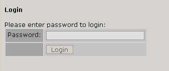
4. Должно появиться главное меню. Кликните на ссылку Firmware Update.
5. Появится экран Confirm Firmware Update (Подтверждение обновление ПО ) с предупреждением:
«Выполнение обновления потребует остановки управления, измерителей и аудио процессора. Во время обновления звук в эфире не будет прерван, но для активации нового программного обеспечения потребуется перезагрузка устройства, что приведет к прерыванию звука. После загрузки обновления Вы сможете изменить банк загрузки для активации нового программного обеспечения и перезагрузки или продолжать работать на текущей версии ПО и произвести перезагрузку позднее. Вы хотите продолжить процесс обновления?»
Если вы хотите продолжить после прочтения предупреждения, то нажмите кнопку Continue и появится диалог Update File для выбора файла:

6. Нажмите кнопку «Browse», найдите файл обновления, загруженный и сохраненный на Вашем компьютере (см. пункт 1) и выберите его двойным кликом чтобы он появился в поле Update File:, и нажмите кнопку Update. Файл будет загружен в OmniaONE. Это может занять до 5 минут. Шкала выполнения может появиться или нет в зависимости от используемого браузера, но как только файл будет загружен должен появиться следующий экран Update Initiated:
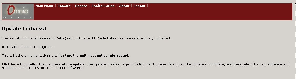
7. Теперь в неактивном банке загружен новый файл ПО. Прочитайте информацию на странице Update Initiated и нажмите на ссылку: Click here to monitor the progress of the update.
Должна появиться страница Installation Progress Monitor (монитор выполнения обновления):
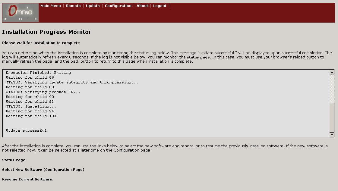
Окно журнала обновляется автоматически каждые 8 секунд.
Примечание: Если окно журнала не отображается в Вашем браузере, то Вы можете нажать на ссылку Status Page для отображения альтернативного журнала. В таком случае Вам будет необходимо вручную обновлять страницу лога кнопкой Reload, а после завершения установки нажать кнопку «Назад» в Вашем браузере для возврата.
Когда внизу лога появится Update Successful (как на рисунке), обновление будет инсталлировано и готово к выбору. Примечание: Для того, чтобы увидеть сообщение «Update Successful», возможно будет необходимо перейти вниз окна лога с помощью полосы или стрелки прокрутки в правой части окна.
8. После сообщения *Update Successful8 нажмите на ссылку: Select New Software (Configuration Page)
9. Перейдите вниз страницы конфигурации, чтобы увидеть раздел Select Software Bank:

В этом примере, новое программное обеспечение было загружено в банк 1.
Видно, что предыдущее программное обеспечение (в банке 0 в данном случае) по-прежнему выбрано и работает.
Вы можете выбрать другой банк для активации нового программного обеспечения или продолжить работу на текущей версии ПО.
Примечание: Для активации нового программного обеспечения потребуется перезагрузка и это вызовет прерывание звука.
В разделе Select Software Bank: выберите банк с новой версией ПО и нажмите кнопку Apply (Применить). В этом примере мы решили активировать новое ПО, выбрали «Bank 1» и нажали кнопку Apply:
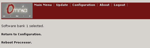
Чтобы активировать выбранный банк нажмите ссылку Reboot Processor. Процессор будет перезагружен и новое программное обеспечение будет активировано.
Если нет возможности немедленно активировать новое ПО, то можно продолжить работу на предыдущей версии. Для этого нажмите ссылку Return to Configuration. Когда Вы будете готовы активировать новую версию ПО вернитесь на страницу конфигурации и повторите пункт 9.
После активации новая версия должна появиться в строке Running Software:
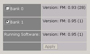
10. Можно закрыть окно браузера. Обновление программного обеспечения завершено.
Примечание: для обновления с версии 1.1 и более ранних до версий 2.х потребуется повторить эту процедуру как было замечено в начале этого документа.

iii
Omnia.ONE FM Quick-Start Setup
We know that you’re probably in a hurry to begin using your new Omnia.ONE FM. If you have technical expertise and
previous knowledge of audio processor fundamentals, using this Quick-Start guide will get you up and running as quickly
as possible. Please refer to the full User Manual for additional installation and setup information.
The following illustrations show the location of the various controls and connectors associated with the installation:
Headphone Jack Headphone Level Control
Jog Wheel
Main Menu / G/R Metering LCD Display Level Meters
1. Install the Omnia.ONE in the equipment rack using at least two rack screws. If only two screws are used, they MUST
be installed in the bottom holes of the rack ears!
2. Connect the audio inputs that are appropriate for your installation. The Omnia.ONE accepts balanced line-level analog
audio via the XLR connectors, AES/EBU digital via the bottom RJ-45 jack (using the “StudioHub” standard pinout) or
Livewire.
NOTE: Livewire audio I/O is only to be used if you have an existing Axia or other Livewire system. Otherwise, the
Livewire Ethernet jack can be used to remote control the Omnia.ONE via its built-in webpage interface. See Appendix
C in the full User Manual for details.
3. Connect the audio outputs in a manner that is appropriate for your installation. We suggest using the composite MPX
BNC outputs (and therefore the Omnia’s built-in MPX stereo generator) if at all possible for best performance.
4. Connect AC power to the unit (there is no power switch!)
5. Navigate to the Input/Output / Meter Select setting and select Input.
6. Navigate to the Input/Output / Input / Input Src setting and select the Analog, AES/EBU or Livewire input as
appropriate for your installation. If your audio source is active, you should now see meter activity on the LED
bargraph meters.
7. While driving the inputs with typical program material at normal operating level, navigate back up to the Input/Output
/ Input menu (by highlighting and clicking on the “<-EXIT” option) and adjust the appropriate input Level control
until the peak-reading input bargraph meters are peaking up to at least –15 and up to –12 dBFS or a little higher.
8. Navigate to the Input/Output / Output / FM Options submenu and ensure that the Pre-Emphasis, De-emphasis and
BS-412 settings are correct for your system and your location. If you will not be using the Omnia’s built-in stereo
generator, it is very important to ensure that the Omnia is the only device providing the FM pre-emphasis (Pre-
Emphasis ON and De-Emphasis OFF) and that any link between the Omnia’s output and the input to the FM exciter
is fully linear with no codecs. If this is not possible, the Omnia must be located at the transmitter site, driving the FM
exciter directly.