Терморегулятор Omron E5CC относится к новому поколению устройств контроля температуры. Установка этого оборудования гарантирует точность регулировки и поддержание работы обжиговых и лабораторных печей.
Содержание
-
- Как правильно подключить терморегулятор Omron E5CC к муфельной печи
- Почему стоит установить терморегулятор Omron E5CC на муфельную печь
Регулятор Omron способен работать даже в условиях повышенной влажности

Японские терморегуляторы не зря считаются самыми высокоточными в мире. Достаточно посмотреть на перечень их достоинств:
- Жидкокристаллический дисплей. Монитор этой модели отличается увеличенными размерами, наличием подсветки и повышенной контрастностью изображения. Благодаря этому информация будет видна с большого расстояния и под разными углами.
- Производительность работы. Главные характеристики регуляторов – это скорость и точность измерения. Иногда от колебания температуры всего в несколько градусов может зависеть конечный результат исследований. Алгоритм работы регулятора Omron E5CC позволяет поддерживать выставленные параметры в пределах 0,5°С.
- Легкость управления. Автоматическая настройка намного уменьшит затраты времени, а также максимально упростит регулирование температуры во время работы.
- Компактность. Данный прибор можно устанавливать на любые муфельные электропечи SNOL.
Цитата: Во время устранения загрязнений после работы печи, регулятор также можно очищать. Для этого используются неагрессивные моющие средства
Как правильно подключить терморегулятор Omron E5CC к муфельной печи
Изучив инструкцию на русском про терморегулятор Omron E5CC, можно сделать вывод, что это устройство не сложное в эксплуатации. Для любых этапов работы – подключения, настройки или пользования достаточно сделать всего несколько простых шагов. Все операции проводятся путем нажатия клавиш с интуитивно понятными значениями.
Оптимальная температура окружающей среды во время работы прибора – не выше 45 градусов Цельсия
Для регулятора Omron E5CC инструкция на русском языке предусматривает возможность установки на разное оборудование – промышленное, бытовое и лабораторное. В их число входят, в том числе, муфельные печи и сушильные шкафы. При первичном подключении руководством по эксплуатации предусмотрены такие меры:
- Убедиться, что упаковка и сам прибор не носят следы повреждений.
- Осмотреть вентиляционные отверстия вокруг места для монтажа терморегулятора – они должны оставаться свободными для отвода тепла.
- Не стоит сильно затягивать клеммные зажимы.
- Необходимо правильно подсоединить входы питания.
- В месте установки обеспечить отсутствие жидкостей и посторонних предметов.
Если терморегулятор будет подвергаться постоянному нагреву, нужно позаботиться о дополнительном охлаждении или вентиляции

Опишем процесс монтажа на панель электропечи и особенности настройки Omron E5CC:
- Вставить устройство в специальное отверстие.
- Для обеспечения водонепроницаемости использовать прокладку.
- Предварительно закрепить регулятор, надев переходник от клеммного блока.
- Поочередно затянуть два крепежных винта.
Для подключения терморегулятора к компьютеру используется стандартный кабель USB
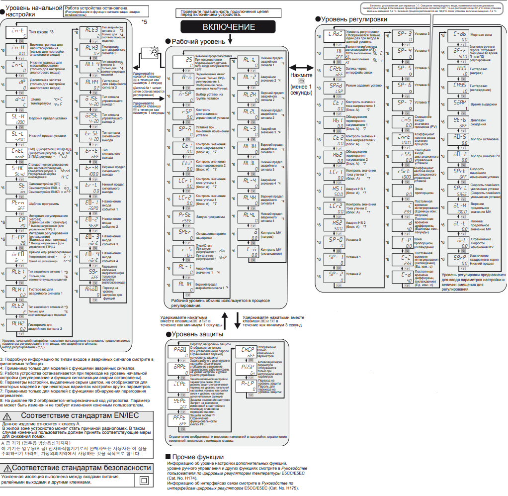
После включения питания на дисплее автоматически отображается эксплуатационный уровень. Чтобы изменить параметры, нужно перейти на одну из таких систем настроек:
- Первоначальной подготовки.
- Регулирования.
- Расширенной функциональности.
- Передачи информационных данных.
При выставлении настроек не забудьте выбрать единицы измерения температуры — ºC или °F

Какие функции еще входят в инструкцию по программированию Omron E5CC, наглядно можно посмотреть в представленном видео:
Почему стоит установить терморегулятор Omron E5CC на муфельную печь
Как видим, терморегулятор Omron E5CC способен контролировать множественные рабочие функции лабораторных печей. Его отличительными особенностями являются:
- 2Пид-регулирование.
- Наличие аналоговых входов.
- Небольшие габариты.
- Возможность использования интерфейса RS-485.
- Датчики сигналов о неисправностях.
- Работа с термопарами разных типов.
- Простая инструкция по настройке и управлению.
- Контрастный ЖК-дисплей с крупноразмерными цифрами, видными издалека.
Любые лабораторные исследования или работа с образцами предусматривают точное соблюдение температурных параметров. Использование терморегуляторов Omron E5CC дает возможность обеспечить необходимые условия для проведения опытов.
Производитель обеспечивает техническую поддержку для устройств любого типа. Сотрудники более 200 сервисных центров по всему миру помогут быстро устранить неисправности и произвести замену нужных деталей.
Еще один бонус – гарантия единой цены на устройства во всех странах

По всем вопросам эксплуатации и приобретения терморегуляторов обращайтесь в компанию «Лабор».
Предписание
В этом руководстве описаны функции, рабочие параметры и области применения для оптимального использования продукта. Пожалуйста, соблюдайте следующие правила при использовании этого продукта:
• Этот продукт предназначен для использования только квалифицированным персоналом, знакомым с электрическими системами.
• Внимательно прочтите и усвойте содержание данного руководства перед использованием оборудования, чтобы обеспечить правильную работу оборудования.
Типы подключаемых датчиков и входов
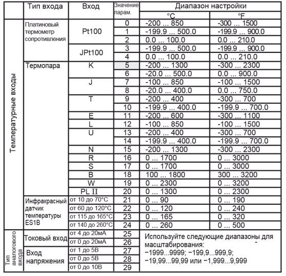
Примечание:
- Значение по умолчанию: 5.
- S.ERR отображается, если при подключении платинового термометра сопротивления
соответствующим образом не будет настроен тип входа. Для снятия отображения S.ERR необходимо правильно выполнить подсоединения при этом выключить и снова включить
питание.
Программирование и настройка прибора
Список возможных ошибок
В случае возникновения ошибки на дисплее № 1 отображается код ошибки.
Примите необходимые меры в соответствии с кодом ошибки, руководствуясь таблицей ниже.
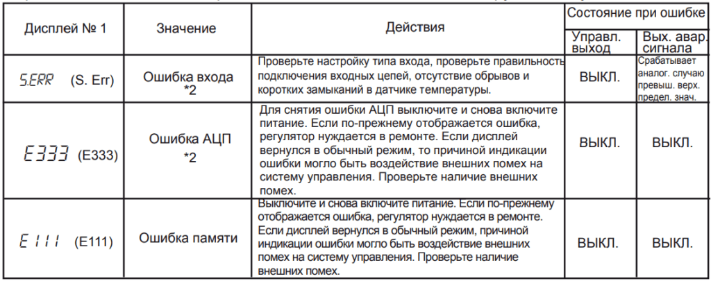
Примечание:
Если входной сигнал находится в пределах диапазона регулирования, но выходит за диапазон отображения значений на дисплее (-1999…9999), на дисплее отобразится [[[[, если значение меньше -1999, и ]]]], если значение больше 9999. При такой индикации выходы управления и сигнализации аварий работают в своем обычном режиме.
*2: Ошибка отображается только в режиме «Значение процесса / Уставка».
В других режимах ошибка не отображаются.
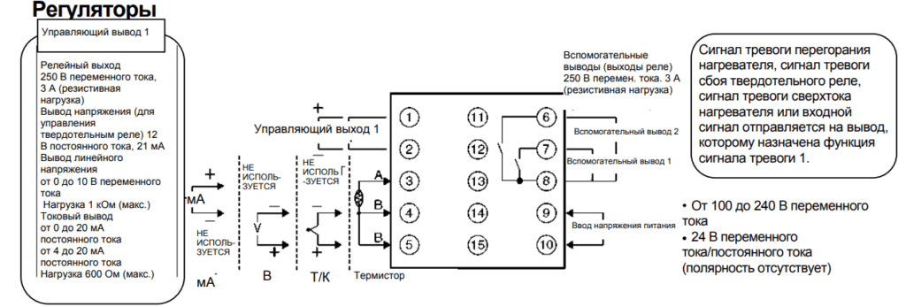
Схема подключения прибора
Внимание!
Выход напряжения (выход управления срабатыванием твердотельного реле) не изолирован гальванически от внутренних цепей. При использовании заземленной термопары не подключайте к земле какие-либо управляющие выходные клеммы. Если клеммы выхода управления подключен к земле, измеренные значения температуры будут неправильными из-за тока утечки.
Скачать полную документацию.
RU
E5CC
Digital Controller
EN
INSTRUCTION MANUAL
Thank you for purchasing the OMRON E5CC Digital Controller.
This manual describes the functions, performance, and
application methods needed for optimum use of the product.
Please observe the following items when using the product.
• This product is designed for use by qualified personnel with
a knowledge of electrical systems.
• Before using the product, thoroughly read and understand
this manual to ensure correct use.
• Keep this manual in a safe location so that it is available for
reference whenever required.
OMRON Corporation
©All Rights Reserved
Refer to the E5□C Digital Controllers User’s Manual (Cat. No. H174)
for detailed application procedures.
Safety Precautions
Key to Warning Symbols
Indicates a potentially hazardous situation which, if
not avoided, is likely to result in minor or moderate
injury or property damage. Read this manual
CAUTION
carefully before using the product.
5377443-6A
CC1
Wiring
Dimensions
Dimensions (mm)
Solderless terminal size
(64)
4
60
48×48
1
* Do not remove the terminal block. Doing so may result in failure or malfunction.
* A Setup Tool port is provided on the upper of the product. Use this port to connect a personal computer to the product when using
the Setup Tool. E58-CIFQ2 USB-Serial Conversion Cable is required to connect the personal computer to the product. (Do not use
the product with the USB-Serial Conversion Cable left permanently connected.)
Refer to the instruction manual provided with the USB-Serial Conversion Cable for details on connection methods.
Names of Parts on Front Panel
• °C / °F : temperature unit
The temperature unit is displayed when the displayed value
is a temperature. Either C or F is displayed according to
the set value of the temperature unit.
•
Level key
Use this key to change levels:
•
Mode key
Press this key to change the contents of the display.
Press this button for 1 s or longer for reverse scroll.
• Press the O key and the M key together for at
least 3 seconds to switch to protect level.
• Shift key (PF key)
The default PF Setting parameter is for shifting the digit.
This is a function key. When it is pressed, the function
set for the PF Setting parameter will operate.
Operation Menu
Input Type
Input type
Input
Setting
Setting range
°C
°F
0
-200 to 850
-300 to 1500
Platinum
Pt100
1
resistance
-199.9 to 500.0
-199.9 to 900.0
thermometer
2
0.0 to 100.0
0.0 to 210.0
3
-199.9 to 500.0
-199.9 to 900.0
JPt100
4
0.0 to 100.0
0.0 to 210.0
K
5
-200 to 1300
-300 to 2300
Thermocouple
6
-20.0 to 500.0
0.0 to 900.0
J
7
-100 to 850
-100 to 1500
8
-20.0 to 400.0
0.0 to 750.0
T
9
-200 to 400
-300 to 700
10
-199.9 to 400.0
-199.9 to 700.0
11
-200 to 600
-300 to 1100
E
L
12
-100 to 850
-100 to 1500
U
13
-200 to 400
-300 to 700
14
-199.9 to 400.0
-199.9 to 700.0
N
15
-200 to 1300
-300 to 2300
R
16
0 to 1700
0 to 3000
S
17
0 to 1700
0 to 3000
B
18
100 to 1800
300 to 3200
W
19
0 to 2300
0 to 3200
PL II
20
0 to 1300
0 to 2300
21
0 to 90
0 to 190
Infrared
10 to 70°C
22
Thermosensor
60 to 120°C
0 to 120
0 to 240
ES1B
115 to 165°C
23
0 to 165
0 to 320
140 to 260°C
24
0 to 260
0 to 500
4 to 20mA
25
Current input
0 to 20mA
Use the following ranges for scaling: -1999
26
to 9999, -199.9 to 999.9, -19.99 to 99.99,
1 to 5V
27
Voltage input
0 to 5V
28
-1.999 to 9.999
0 to 10V
29
*The default is»5″.
*s. e rr will be displayed when a platinum resistance thermometer is mistakenly connected
while input type is not set for it. To clear the s. e rr display, correct the wiring and cycle the
power supply.
Alarms
Alarm output function
Alarm type
Setting
Positive alarm value (X) Negative alarm value (X)
0
No alarm function
Output off
Vary with
*1
Deviation upper/lower limit
1
«L», «H» values
X
X
Deviation upper limit
ON
ON
2
OFF
OFF
SP
SP
X
ON
Deviation lower limit
ON
3
OFF
OFF
SP
SP
L H
Vary with
ON
*1
Deviation upper/lower range
4
«L», «H» values
OFF
SP
Deviation upper/lower limit
L H
Vary with
*1
5
ON
«L», «H» values
standby sequence ON
OFF
SP
X
X
Deviation upper limit
ON
ON
6
OFF
standby sequence ON
OFF
SP
SP
X
Deviation lower limit
ON
ON
7
standby sequence ON
OFF
OFF
SP
SP
X
X
ON
ON
8
Absolute value upper limit
OFF
OFF
0
X
X
ON
ON
9
Absolute value lower limit
OFF
OFF
0
X
Absolute value upper limit
ON
ON
10
OFF
OFF
standby sequence ON
0
X
Absolute value lower limit
ON
11
ON
standby sequence ON
OFF
OFF
0
12
LBA (only for alarm 1)
13
PV Change Rate Alarm
X
ON
ON
14
SP absolute value upper limit
OFF
OFF
0
X
ON
15
SP absolute value lower limit
ON
OFF
OFF
0
X
ON
ON
16
MV absolute value upper limit
OFF
OFF
0
X
ON
MV absolute value lower limit
ON
17
OFF
OFF
0
X
ON
ON
18
RSP absolute value upper limit
OFF
OFF
0
X
ON
19
RSP absolute value lower limit
ON
OFF
OFF
0
*1: Upper and lower limits can be set for parameters 1, 4 and 5 to
provide for different types of alarm. These are indicated by the
letter «L» and «H».
• The default alarm type is «2»
Conformance to EN/IEC Standards
This is a class A product.
In residential areas it may cause radio interference, in which case the user
may be required to take adequate measures to reduce interference.
A 급 기기 (업무용 방송통신기자재)
이 기기는 업무용(A 급) 전자파적합기기로서 판매자또는 사용자는 이 점을
주의하시기 바라며, 가정외의지역에서 사용하는 것을 목적으로 합니다.
Warning Symbols
CAUTION
Minor injury due to electric shock may occasionally occur.
Do not touch the terminals while power is being supplied.
Electric shock, fire, or malfunction may occasionally occur. Do not allow metal objects, conductors,
cuttings from installation work, or moisture to enter the Digital Controller, the Setup Tool ports, or
between the pins on the connectors on the Setup Tool cable.
Do not use the product where subject to flammable or explosive gas. Otherwise, minor injury from
explosion may occasionally occur.
Never disassemble, modify, or repair the product or touch any of the internal parts. Minor electric
shock, fire, or malfunction may occasionally occur.
CAUTION — Risk of Fire and Electric Shock
a) This is the product UL listed as Open Type Process Control Equipment. It must be mounted in an enclosure
that does not allow fire to escape externally.
b) More than one disconnect switch may be required to de-energize the equipment before servicing.
c) Signal inputs are SELV, limited energy.
d) Caution: To reduce the risk of fire or electric shock, do not interconnect the outputs of different Class 2 circuits.
If the output relays are used past their life expectancy, contact fusing or burning may occasionally occur.
Always consider the application conditions and use the output relays within their rated load and
electrical life expectancy. The life expectancy of output relays varies considerably with the output load
and switching conditions.
Loose screws may occasionally result in fire. Tighten the terminal screws to the specified torque of 0.43
to 0.58 N•m.
Set the parameters of the product so that they are suitable for the system being controlled. If they are
not suitable, unexpected operation may occasionally result in property damage or accidents.
A malfunction in the Digital Controller may occasionally make control operations impossible or prevent
alarm outputs, resulting in property damage. To maintain safety in the event of malfunction of the Digital
Controller, take appropriate safety measures, such as installing a monitoring device on a separate line.
Suitability for Use
Omron Companies shall not be responsible for conformity with any standards, codes or regulations which
apply to the combination of the Product in the Buyer’s application or use of the Product.
At Buyer’s request, Omron will provide applicable third party certification documents identifying ratings and
limitations of use which apply to the Product. This information by itself is not sufficient for a complete
determination of the suitability of the Product in combination with the end product, machine, system, or
other application or use. Buyer shall be solely responsible for determining appropriateness of the particular
product with respect to Buyer’s application, product or system. Buyer shall take application responsibility in
all cases.
NEVER USE THE PRODUCT FOR AN APPLICATION INVOLVING SERIOUS RISK TO LIFE OR
PROPERTY WITHOUT ENSURING THAT THE SYSTEM AS A WHOLE HAS BEEN DESIGNED TO
ADDRESS THE RISKS, AND THAT THE OMRON PRODUCT(S) IS PROPERLY RATED AND INSTALLED
FOR THE INTENDED USE WITHIN THE OVERALL EQUIPMENT OR SYSTEM.
Installation
Individual mounting (mm)
M3
In the pack:
44.8×44.8
*Main unit
*Instruction manual
*Watertight packing (Y92S-P8):
*Adapter (Y92F-49):
*Terminal cover (Provided only for
+0.6
□□□□
□
models with E5CC-
5
):
45
0
Sold Separately
*Terminal cover (E53-COV23)
*USB-Serial Conversion Cable
(E58-CIFQ2)
• Insert the main unit through the mounting hole in the panel (1 to 5 mm thickness). Insert the
mounting brackets (supplied) into the fixing slots located on the top and bottom of the rear
case.
• Tighten the two mounting screws on the top and bottom of the adapter to keep them
balanced, and finally tighten them to a torque of between 0.29 and 0.39 N·m.
• When more than one machine is installed, make sure that the ambient temperature does
not exceed the specified limit.
Operation indicators
•
• SUB1: Auxiliary output 1 indicator
No.1 display
• SUB2: Auxiliary output 2 indicator
Process value or set data type
• SUB3: Auxiliary output 3 indicator
• OUT1: Control output 1 indicator
•
• OUT2: Control output 2 indicator
No.2 display
Set point, set data read-out value or changed input
•
RSP: Remote SP indicator
value
Lit when the assigned function is ON.
•
Up and Down keys
•
Each press of U key increments or advances the
TUNE:
values displayed on the No.2 display.
Flashing during self-tuning.
Each press of D key decrements or returns the
Lit during auto-tuning.
values displayed on the No.2 display.
Operation stopped.
Initial Setting Level
(Control/alarm are both stopped.)
alt3
in-t
Alarm 3
Input Type *3
*6
2
Type
5
M
M
Scaling Upper Limit
in-h
alh3
Alarm 3
(only when setting
*6
*6
Hysteresis
100
0.2
analog input)
M
M
Scaling Lower Limit
alt4
in-l
Alarm 4
(only when setting
*6
*6
Type
0
2
analog input)
M
M
Decimal Point
dp
alh4
Alarm 4
(only when setting
*6
*6
Hysteresis
0
0.2
analog input)
M
M
c
°C=
o1st
d-u
Temperature
Control Output 1
f
*6
*6
°F=
Unit
Signal
c
4-20
M
M
trst
sl-h
Transfer
*6
SP Upper Limit
Output Signal
4-20
1300
M
M
tr-t
sl-l
Transfer
SP Lower Limit
*6
Output Type
off
-200
M
M
PID•ON/OFF
tr-h
cntl
Transfer Output
onof
In ON/OFF control =
*6
100.0
onof
Upper Limit
pid
In 2-PID control =
M
M
Standard or Heating/Cooling
tr-l
s-hc
Transfer Output
stnd
*6
Standard control =
Lower Limit
0.0
stnd
h-c
Heating and cooling control =
M
M
ev-1
st
ST (Self-Tuning)
Event Input
*6
*6
on
Assignment 1
ST ON =
msp0
on
ST OFF =
off
M
M
ev-2
ptrn
Event Input
Program Pattern
*6
Assignment 2
stop
off
M
M
cp
Control Period (Heating)
ev-3
Event Input
*6
*6
(Unit: Seconds)
Assignment 3
none
20
*Voltage output (for driving SSR): 2
M
M
ev-4
c-cp
Control Period (Cooling)
Event Input
*6
*6
(Unit: Seconds)
Assignment 4
none
20
*Voltage output (for driving SSR): 2
X
M
M
Extraction of Square
orev
Direct/Reverse Operation
sqr
Root Enable
or-r
*6
In Reverse operation (Heating) =
(Only when analog
or-r
off
input is set)
or-d
In Direct operation (Cooling) =
M
M
alt1
amov
Move to Advanced
Alarm 1 Type:
*3
*6
Function Setting
*6
Specified models only
2
*4
0
Level
M
M
alh1
X
Alarm 1 Hysteresis
*6
0.2
M
alt2
Alarm 2 Type:
0
*3
*6
Specified models only
2
*4
M
0
X
alh2
Alarm 2 Hysteresis
*6
0
0.2
X
M
0
Initial setting level enables users to specify their preferred
operating conditions (input type, alarm type, control method, etc.)
*3: Refer to the adjoining tables for details of input types and alarm types.
X
*4: Applicable only to models with alarm functions.
*5: Operation is stopped when moved to the initial setting level.
0
(control/alarm are both stopped.)
X
*6: The grayed-out setting items are not displayed for some models and
0
some settings of other setting items.
X
*7: Applicable only to models with heater burnout functions.
0
*8: The four numeric digits of the product code are displayed in the No. 2
X
display. The setting cannot be changed and there is nothing that you
need to set.
0
X
0
Conformance to Safety Standard
X
0
Reinforced insulation is provided between input power
supply, relay outputs, and between other terminals.
Due to UL Listing requirements, use the E54-CT1L or E54-CT3L
current transformer with the factory wiring (internal wiring).
Use a UL category XOBA or XOBA7 current transformer that is UL
Listed for field wiring (external wiring) and not the factory wiring
(internal wiring).
Always externally connect the recommended fuse that is specified
in the Instruction Manual before you use the Digital Controller.
Analog Input
• If you input an analog voltage or current, set the Input Type
parameter to the correct input type.
• Do not use the Digital Controller to measure a circuit with
Measurement Category II, III, or IV.
• Do not use the Digital Controller to measure an energized circuit to
which a voltage that exceeds 30 Vms or 60 VDC is applied.
The protection provided by the Digital Controller may be impaired if the
Digital Controller is used in a manner that is not specified by the
manufacturer.
Precautions for Safe Use
Be sure to observe the following precautions to prevent operation failure, malfunction, or adverse affects on the
performance and functions of the product. Not doing so may occasionally result in unexpected events.
Use the product within specifications.
(1) The product is designed for indoor use only. Do not use the product outdoors. Do not use or store the product
in any of the following locations.
•Places directly subject to heat radiated from heating equipment.
•Places subject to splashing liquid or oil atmosphere.
•Places subject to direct sunlight.
•Places subject to dust or corrosive gas (in particular, sulfide gas and ammonia gas).
•Places subject to intense temperature change.
•Places subject to icing and condensation.
•Places subject to vibration and large shocks.
(2) Use/store within the rated temperature and humidity ranges. Provide forced-cooling if required.
(3) To allow heat to escape, do not block the area around the product.
Do not block the ventilation holes on the product.
(4) Be sure to wire properly with correct polarity of terminals.
(5) Use the specified size of crimped terminals (M3, width 5.8 mm or less) for wiring. To connect bare wires to the
terminal block, use copper braided or solid wires with a gage of AWG24 to AWG18 (equal to cross- sectional
area of 0.205 to 0.8231 mm
2
). (The stripping length is 6 to 8 mm.) Up to two wires of same size and type, or
two crimped terminals can be inserted into a single terminal.
(6) Do not wire the terminals which are not used.
(7) Allow as much space as possible between the controller and devices that generate a powerful high- frequency
or surge. Separate the high-voltage or large-current power lines from other lines, and avoid parallel or
common wiring with the power lines when you are wiring to the terminals.
(8) Use this product within the rated load and power supply.
(9) Make sure that the rated voltage is attained within two seconds of turning ON the power using a switch or relay
contact. If the voltage is applied gradually, the power may not be reset or output malfunctions may occur.
(10) Make sure that the Digital Controller has 30 minutes or more to warm up after turning ON the power before
starting actual control operations to ensure the correct temperature display.
(11) When executing self-tuning, turn the load and the unit ON simultaneously, or turn the load ON before you turn
the controller ON.
(12) A switch or circuit breaker should be provided close to this unit. The switch or circuit breaker should be within
easy reach of the operator, and must be marked as a disconnecting means for this unit.
(13) Wipe off any dirt from the Digital Controller with a soft dry cloth. Never use thinners, benzine, alcohol, or any
cleaners that contain these or other organic solvents. Deformation or discoloration may occur.
(14) Design system (control panel, etc) considering the 2 second of delay that the controller’s output to be set after
power ON.
(15) The output will turn OFF when you move to the Initial Setting Level. Take this into consideration when
performing control.
(16) The number of non-volatile memory write operations is limited. Therefore, use RAM write mode when
frequently overwriting data during communications or other operations.
(17) When disassembling the Temperature Controller for disposal, use suitable tools.
(18) Do not exceed the communications distance that is given in the specifications and use the specified
communications cable. Refer to the E5□C Digital Controllers User’s Manual (Cat. No.H174) for the
communications distance and cable specifications.
(19) Do not turn the power supply to the Digital Controller ON or OFF while the USB-Serial Conversion Cable is
connected. The Digital Controller may malfunction.
(20) The maximum terminal temperature is 75°C. Use wires with heat resistance of 75°C min to wire the terminals.
Side-by-side mounting (mm)
+1
(48 x number of units — 2.5)
0
Waterproofing is impossible
with side-by-side
installation. When
waterproofing is required, fit
watertight packing on the
backside of front panel.
•
STOP: Control stopped indicator
Lit when «Run/Stop» is stopped during operation.
During control stop, functions other than control output
are valid.
•
CMW: Communications writing
enabled/disabled indicator
Lit when communications writing is enabled and not lit
when it is disabled.
•
:Protection indicator
Lit when Setting Change Protect is
ON (disables the Up and Down Keys).
• MANU: Manual output indicator
Lit when the Auto/Manual Mode is set
to Manual Mode.
Check the wiring before turning ON the power supply.
*5
POWER ON
*3
*4
Operation Level
Process Value/Set Point
25
al1l
s.err is displayed when
*6
connected sensor is
*3
0
different from input type.
*4
M
Hold O down
a-m
al-2
Auto/Manual Switch
for at least
*6
*6
PID control only.
3 seconds
M
(No.1 display flashes,
then the control stops.)
m-sp
al2h
Multi-SP
*6
*6
Set Point Selection
0
M
Hold O down
rsp
al2l
for at least
*6
Remote SP Monitor
*6
0.0
1 second
M
sp-m
al-3
Set Point During
*6
*6
SP Ramp
0
M
ct1
Heater Current 1
al3h
*6
*6
Value Monitor
0.0
*7
(Unit: A)
M
ct2
Heater Current 2
al3l
*6
*6
Value Monitor
0.0
*7
(Unit: A)
M
lcr1
Leakage Current 1
al-4
*6
*6
Value Monitor
0.0
*7
(Unit: A)
M
lcr2
Leakage Current 2
al4h
*6
*6
Value Monitor
0.0
(Unit: A)
*7
M
prst
al4l
*6
Program Start
*6
rset
M
sktr
*6
Soak Time Remain
*6
0
M
r-s
RUN/STOP
c-o
run
*6
When control start =
*6
run
stop
When control stop =
M
al-1
*6
Alarm Value 1
*4
0
M
al1h
Alarm Value Upper Limit 1
*6
*4
0
M
Operation level should normally be used during operations.
Hold O and M keys
Hold O and M keys
down for at least
down for at least
1 second
3 seconds
Protect Level
Move to Protect Level
pmov
chgp
Displayed only when a
password is set. Restricts
0
off
moving to Protect Level.
M
Operation / Adjustment Protect
oapt
Restricts displaying and
pmsk
modifying menu items in
0
Operation, Adjustment,
and Manual Control Levels.
M
Initial Setting / Communication Protect
icpt
prlp
Restricts movement to the
Initial Setting, Communications
1
Setting, and Advanced Function
M
Setting Levels.
wtpt
Setting Change Protect
Restricts changes to settings
off
by operating the front panel keys.
M
pfpt
PF Key Protect
Restricts PF key operation.
off
M
Restricts which settings can be displayed or changed, and
restricts change by key operation.
Other functions
Refer to the E5□C Digital Controllers User’s Manual (Cat. No.
H174) for information on the Advanced Function Setting Level,
Manual Control Level, and other functions.
Refer to the E5□C Digital Controllers Communications Manual (Cat.
No. H175) for information on communications.
Specifications
Power supply voltage
Operating voltage range
Power consumption
Option 000:
All other specifications:
Indication accuracy
(Ambient temperature: 23°C)
Event input
Contact input
No-contact input
Remote SP input
Control output 1
Control output 2
Control method
Auxiliary outputs
Transfer output
Ambient temperature
Ambient humidity
Storage temperature
Altitude
Recommended fuse
Weight
Degree of protection
Installation environment
Memory protection
Temporary overvoltage
Connections
(The applicability of the electric terminals varies with the type of machine.)
Do not connect anything to the terminals that are shaded gray.
Control output 1
Control output 2
Auxiliary outputs 1, 2, and 3
Voltage output (for driving SSR)
Relay output
Current output
Relay outputs
12 VDC, 21 mA
250 VAC, 3 A (resistive load)
0 to 20 mA DC
two outputs 250 VAC: 3 A
4 to 20 mA DC
Voltage output (for driving SSR)
(resistive load)
Load: 500 Ω max.
12 VDC, 21 mA
three outputs 250 VAC: 2 A
(resistive load)
*1 Control Outputs 1 and 2
RX
QX
CX
CQ
One relay
One voltage output
One linear
Two voltage outputs
Linear current output/
output
(for driving SSR)
current output
(for driving SSR)
voltage output (for driving SSR)
OUT1
OUT1
OUT1
OUT1
1
1
1
1
1
+
+
+
R
Q
C
Q
−
−
−
2
2
2
2
2
OUT2
+ Q
3
3
3
3
3
1
2
3
*2 Sensor Temperature/Analog Input
4
TC
Pt
I
V
5
A
+
4
4
4
4
6
−
B
mA
−
5
5
5
5
−
B
V
6
6
6
6
+
+
*5 Options
001
002
003
004
Event inputs 1 and 2,
Communications
Communications
Communications (RS-485)
and event inputs 3 and 4
and CT1
(RS-485) and CT1
(RS-485), CT1, and CT2
(−)
B(+)
B(+)
B(+)
13
13
13
13
RS-485
RS-485
RS-485
14
14
14
14
EV1
A(−)
A(−)
A(−)
15
15
15
15
EV2
(−)
16
16
16
16
CT1
CT1
CT1
17
17
17
17
COM
EV3
CT2
18
18
18
18
EV4
* When complying with EMC standards, the line connecting the sensor must be 30 m or less.
If the cable length exceeds 30 m, compliance with EMC standards will not be possible.
* Use non-voltage inputs for the event inputs. The polarity for a non-contact input is indicated by «(-).»
Only the value set to the ins: Temperature Input Shift parameter is applied to the entire temperature input range.
When the process value is 200°C, the process value is treated as 201.2°C after input shift if the input shift value
is set to 1.2°C. The process value is treated as 198.8°C after input shift if the input shift value is set to -1.2°C.
Adjustment Level
l.adj
Adjustment Level
*8
Displayed only once when
entering Adjustment Level.
M
AT Execute / Cancel
at
at-2
*6
100%AT Execute
off
at-1
40%AT Execute
Alarm Value
M
Lower Limit 1 *4
0
cmwt
Communications Writing
M
*6
off
Press O
Alarm Value 2 *4
M
(less than
0
spmd
1 second)
SP Mode
M
*6
lsp
Alarm Value
M
Upper Limit 2 *4
0
ct1
Heater Current 1 Value
M
*6
Monitor (Unit: A)
*7
0.0
Alarm Value
M
Lower Limit 2 *4
0
hb1
Heater Burnout Detection 1
M
*6
(Unit: A)
*7
0.0
Alarm Value 3 *4
M
0
ct2
Heater Current 2 Value
M
*6
Monitor (Unit: A)
*7
0.0
Alarm Value
M
Upper Limit 3 *4
0
hb2
Heater Burnout Detection 2
M
*6
(Unit: A)
*7
0.0
Alarm Value
M
Lower Limit 3 *4
0
lcr1
Leakage Current 1 Value
M
*6
Monitor (Unit: A)
*7
0.0
M
Alarm Value 4 *4
0
hs1
HS Alarm 1
M
*6
(Unit: A)
*7
50.0
Alarm Value
M
Upper Limit 4 *4
0
lcr2
Leakage Current 2 Value
M
*6
Monitor (Unit: A)
*7
0.0
Alarm Value
M
Lower Limit 4 *4
0
hs2
HS Alarm 2
*6
M
50.0
(Unit: A)
*7
o
MV Monitor
M
(Heating)
0.0
sp-0
SP 0
*6
M
0
MV Monitor
M
(Cooling)
0.0
sp-1
SP 1
M
*6
0
M
sp-2
SP 2
*6
0
M
Adjustment level is for entering set values and shift values for control.
Error Display (troubleshooting)
When an error has occurred, the No.1 display shows the error code. Take necessary measure
according to the error code, referring the table below.
No.1 display
Meaning
Check the setting of the Input Type parameter,
s.err
Input error
(S. Err)
check the input wiring, and check for broken or
*2
Changed
shorts in the temperature sensor.
Parameters Only
After the correction of A/D converter error, turn the
power OFF then back ON again. If the display
M
A/D converter error
remains the same, the controller must be repaired.
e333
Parameter Mask
(E333)
*2
If the display is restored to normal, then a
Enable
probable cause can be external noise affecting the
Displayed only
on
control system. Check for external noise.
when a parameter
mask is set.
M
Turn the power OFF then back ON again. If the
Password to Move
display remains the same, the controller must be
e111
Memory error
to Protect Level
repaired. If the display is restored to normal, then
(E111)
a probable cause can be external noise affecting
0
the control system. Check for external noise.
M
If the input value exceeds the display limit (-1999 to 9999), though it is within the control
range, [[[[ will be displayed under -1999 and ]]]] above 9999. Under these conditions,
control output and alarm output will operate normally.
Refer to the E5□C Digital Controllers User’s Manual (Cat. No. H174) for the controllable ranges.
*2: Error shown only for «Process value / Set point». Not shown for other status.
OMRON EUROPE B.V.
Wegalaan 67-69, NL-2132 JD Hoofddorp The Netherlands
Phone 31-2356-81-300
FAX 31-2356-81-388
OMRON ELECTRONICS LLC
One Commerce Drive Schaumburg, IL 60173-5302 U.S.A
Phone 1-847-843-7900
FAX 1-847-843-7787
OMRON ASIA PACIFIC PTE. LTD.
No. 438A Alexandra Road # 05-05/08 (Lobby 2),
Alexandra Technopark, Singapore 119967
Phone 65-6835-3011
FAX 65-6835-2711
OMRON Corporation
Shiokoji Horikawa, Shimogyo-ku, Kyoto 600-8530 JAPAN
100 to 240 VAC, 50/60 Hz or
24 VAC, 50/60 Hz / 24 VDC
85 to 110% of the rated voltage
5.2 VA max. (100 to 240 VAC)
3.1 VA max. (24 VAC)/1.6 W max. (24 VDC)
6.5 VA max. (100 to 240 VAC)
4.1 VA max. (24 VAC)/2.3 W max. (24 VDC)
Thermocouple:
(±0.3 % of indication value or ±1°C,
whichever is greater) ±1 digit max.
Platinum resistance thermometer:
(±0.2 % of indication value or ±0.8°C,
whichever is greater) ±1 digit max.
Analog input:
±0.2 % FS ±1 digit max.
Output current: approx. 7 mA per contact.
ON:1 kΩ max., OFF: 100 kΩ min.
ON: residual voltage 1.5 V max.,
OFF: leakage current 0.1 mA max.
4 to 20 mA DC or 0 to 20 mA DC
0 to 5 V DC or 1 to 5 V DC or 0 to 10 V DC
Relay output :SPST-NO
250VAC, 3A(resistive load)
Electrical life of relay: 100,000 operations
Voltage output (for driving SSR):
12 VDC ±20%, 21 mA
Current output: 4 to 20 mA DC, 0 to 20mA DC
Load: 500 Ω max.
Voltage output (for driving SSR):
12 VDC, 21 mA
ON/OFF or 2-PID control
Relay outputs:SPST-NO, 250 VAC,
two outputs: 3 A (resistive load),
three outputs: 2 A (resistive load),
Electrical life of relay: 100,000 operations
4 to 20 mA DC with load of 500 Ω max.
1 to 5 VDC with load of 1 kΩ min.
-10 to 55°C
(Avoid freezing or condensation)
25% to 85%
-25 to 65°C
(Avoid freezing or condensation)
Max. 2,000m
T2A, 250 VAC, time-lag, low-breaking capacity
Approx. 120 g (Digital Controller only)
Front panel: IP66
Rear case: IP20, Terminal section: IP00
Installation category II, pollution
degree 2 (as per IEC61010-1)
Non-volatile memory
(Number of write operations: 1,000,000)
Short term: 1200 V+ (power supply voltage)
Long term: 250 V+ (power supply voltage)
E5CC
1. Control outputs
5. Options
The E5CC is set for a K thermocouple (input type of 5)
by default. If a different sensor is used, an input error
(s.err) will occur.
Check the setting of the Input Type parameter.
*3 Auxiliary Outputs
Auxiliary outputs 1 and 2 Auxiliary outputs 1, 2, and 3
OUT1
+
C
7
7
—
OUT2
Auxiliary output 3
Auxiliary output 2
Q
+
8
8
Auxiliary output 2
9
9
Auxiliary output 1
Auxiliary output 1
10
10
13
7
14
8
Check for a single-fault condition of the COM t
erminal before use if auxiliary outputs 1,2 and 3
15
9
will be connected to different electrical potentials.
16
10
*4 Input Power Supply
17
11
100 to 240 VAC
24 VAC/DC
18
12
11
11
12
12
(no polarity)
005
006
007
Event inputs 1 to 4
Event inputs 1 and 2, and
Event inputs 1 and 2,
and remote SP
transfer output
(−)
(−)
(−)
13
13
13
14
14
14
EV1
EV1
EV1
15
15
15
EV2
EV2
EV2
(−)
+
16
16
+
16
+
V
V
+
17
17
17
m
EV3
A
I
18
−
−
18
18
EV4
c-db
sp-3
SP 3
Dead Band
*6
*6
0
0.0
M
M
sp-4
of-r
Manual Reset Value
SP 4
*6
Clears the offset
*6
0
50.0
during P or PD control.
M
M
sp-5
hys
SP 5
Hysteresis (Heating)
*6
*6
0
1.0
M
M
sp-6
chys
SP 6
Hysteresis (Cooling)
*6
*6
0
1.0
M
M
sp-7
soak
SP 7
*6
*6
Soak Time
0
1
M
M
ins
wt-b
PV
*6
*6
Wait Band
Input Shift
0.0
off
M
M
inrt
mv-s
PV input
*6
*6
MV at Stop
Slope Coefficient
1.000
0.0
M
M
rss
mv-e
Remote SP
*6
*6
MV at PV Error
Input Shift
0.0
0.0
M
M
rsrt
sprt
Remote SP input
*6
*6
SP Ramp Set Value
Slope Coefficient
1.000
off
M
M
p
sprl
Proportional
SP Ramp Set Value
*6
*6
Band
8.0
same
(SP Ramp Fall Value)
M
M
i
ol-h
Integral Time
MV Upper Limit
*6
*6
233
(Unit: Seconds)
100.0
M
M
d
ol-l
Derivative Time
*6
*6
MV Lower Limit
(Unit: Seconds)
40
0.0
M
M
c-p
orl
Proportional Band
MV Change
*6
*6
(Cooling)
8.0
Rate Limit
0.0
M
M
Integral Time
c-i
sqrp
Extraction of Square
*6
*6
(Cooling)
Root Low-cut Point
233
0.0
(Unit: Seconds)
M
M
c-d
Derivative Time
plcm
Communications
*6
*6
(Cooling)
Monitor
40
1234
(Unit: Seconds)
M
M
Status at error
Action
Control
Alarm
output
Operates
OFF
as above the
upper limit.
OFF
OFF
OFF
OFF
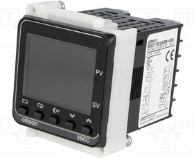
* Изображения служат только для ознакомления,
см. техническую документацию
Добавить в корзину 1 шт.
на сумму 50 130 руб.
Посмотреть альтернативные предложения2
Номенклатурный номер: 8002556088
Артикул: E5CC-RX3A5M-000
Страна происхождения: КИТАЙ
Бренд / Производитель: Omron

Описание
АвтоматикаРегулировка и управлениеРегуляторыРегуляторы температуры
Контроллер температуры цифровой серии E5CC, релейный выход, три вспомогательных выхода, напряжение питания 100..240 VAC, универсальный вход
Технические параметры
| Maximum Operating Temperature | +55°C |
| Minimum Operating Temperature | -10°C |
| Number of Outputs | 1 |
| Output Type | Relay |
| Series | E5CC |
| Size | 48x48mm |
| Supply Voltage | 100 → 240 V ac |
| Вес, г | 147.7 |
Техническая документация
Сроки доставки
Доставка в регион Курск
| Магазин «ЧИП и ДИП» | 5 июля1 | бесплатно |
| ПВЗ Boxberry | 3 июля1 | бесплатно |
| ПВЗ СДЭК | 4 июля1 | бесплатно |
| ПВЗ Л-Пост | 4 июля1 | бесплатно |
| ПВЗ 5Post | 5 июля1 | бесплатно |
| Почта России | 12 июля1 | бесплатно |
| Курьер | 4 июля1 | 416 руб.2 |
| ТК DPD | 3 июля1 | 546 руб.2 |
| ТК «Деловые линии» | 4 июля1 | 824 руб.2 |
Цена и наличие в магазинах
| ул. Карла Маркса, 68, ТЦ «Мега Гринн», 1 этаж | нет в наличии |
Термопара /Термосопротивление / По току / По напряжению
Дискретное вкл/выкл, 2-ПИД регулирование
K, J, E, T, L, N, U, R, S, B, C, P (PLII)
Вход термосопротивления (RTD):
JPt100, Pt100
Вход аналоговый по напряжению:
0-5 В, 1-5 В, 0-10 В
Диапазон регулировки температуры, °C:
-200…+2300
Количество контуров управления:
1
Количество аварийных выходов:
3
Температура эксплуатации Max, °C:
55
Температура эксплуатации Min, °C:
-10
Размер прямоугольного корпуса, мм:
48×48
2 11-сегментных светодиодных LED
Температура эксплуатации, °C:
-10…+55
Бесплатный самовывоз из пунктов выдачи заказов
г. Смоленск, 2-й Рославльский пер., 14 Б, Цокольный этаж, оф 6.
Пн — Пт 8 — 19
Суббота 10 — 17
Воскресенье выходной
Доставка по России
Транспортными компаниями (до терминала либо до двери)
СДЭК, Деловые Линии, ЕМС Почта России, DPD
Оперативная доставка в Санкт-Петербург, Екатеринбург, Новосибирск, Нижний Новгород, Краснодар, Самару, Челябинск, Казань, Пермь, Ростов-на-Дону, Уфу, Воронеж, Ижевск, Иркутск, Красноярск, Белгород.
Доставка в Казахстан и Беларусь
Отправляем товары транспортной компанией СДЭК
Доставка по Москве
Стоимость доставки 350 р. за исключением крупногабаритного товара (обговаривается отдельно)