- Manuals
- Brands
- mru Manuals
- Measuring Instruments
- OPTIMA7 biogas
- User manual
-
Contents
-
Table of Contents
-
Troubleshooting
-
Bookmarks
Quick Links
OPTIMA7 biogas
USER MANUAL
4102EN-BIO
Related Manuals for mru OPTIMA7 biogas
Summary of Contents for mru OPTIMA7 biogas
-
Page 1
OPTIMA7 biogas USER MANUAL 4102EN-BIO… -
Page 2
USER MANUAL OPTIMA7 Biogas Producer: Legal notices / Intellectual property rights comments Original user manual © 2020 by MRU No part of this manual my be published in any form (print, fotocopy, electronic media or any other publication form) without a written approval by the publisher. -
Page 3: Table Of Contents
Automatic Auto-off function ……………. 29 6.3. Measuring with grid power supply / Battery charging ……29 6.4. Battery charge condition …………….29 6.5. Operating temperature ……………… 30 6.6. Controlling Condensate separator (water trap) ……..30 3 / 72 MRU GmbH, D-74172 Neckarsulm…
-
Page 4
USER MANUAL OPTIMA7 Biogas 6.7. Connections and tightness …………….31 6.8. Automatic zero-pint setting …………….31 6.9. Repeating the zeroing ………………32 7 Performing measurement ……….33 7.1. Selecting the measuring program ……………33 7.2. Performing Biogas measurement …………..34 7.3. Flue gas measurement (option) …………..34 7.4. -
Page 5
Performing and checking the update …………..68 In case of error ………………….69 11.6. Troubleshooting ………………..70 Troubleshooting the analyzer …………….70 Troubleshooting condensate separator …………71 12 Declaration of conformity ……….72 5 / 72 MRU GmbH, D-74172 Neckarsulm… -
Page 6: Information For Product And Safety
USER MANUAL OPTIMA7 Biogas Information for product and safety 1.1. Safety manual All general information and safety precautions of MRU products are listed in the supplied separate safety manual. Therefore, this manual must be read and observed before the first use of the instrument .
-
Page 7: Ensure Safety
NO — 3 years. The use of the analyzer for regulatory purposes is subject to special regula- tions (for example a periodical examination of the analyzer). Please obtain the appropriate regulations from your local responsible authority. 7 / 72 MRU GmbH, D-74172 Neckarsulm…
-
Page 8
This area classification is country specific, please observe and notice it. • MRU instruments may be operated in hazardous areas zone 2 by skilled users obeying local guidelines e.g. by using LEL gas detectors… -
Page 9: User Guidelines For Rechargeable Batteries
• Do not cut or squeeze the connecting cables of the rechargeable battery. • Do not connect the (+) contact to the (-) contact or metal. • Non-observance of the above guidelines can cause heat, fire and explo- sions 9 / 72 MRU GmbH, D-74172 Neckarsulm…
-
Page 10: Introduction
USER MANUAL OPTIMA7 Biogas 2 Introduction • This manual enables you to understand and safely operate this MRU Ana- lyzer. • Please read this manual with great vigilant and get familiar with the product before using it. • This analyzer may only be operated by competent personnel and for its intended use.
-
Page 11
The analyzer must be used according to instructions for the intended use. Our analyzers are checked according to the following regulations: VDE 0411 (EN61010) and DIN VDE 0701 before they leave the MRU GmbH factory. MRU technical products are designed and manufactured according to DIN 31000/ VDE 1000 and UVV = VBG 4 of the professional guilds for fine me- chanics and electrical engineering. -
Page 12: About Us
USER MANUAL OPTIMA7 Biogas 2.2. About us The analyzer is produced by the MRU GmbH in Neckarsulm, Germany (Founded in 1984), a medium sized company that specializes in developing, producing and marketing high quality emission monitoring analyzers. MRU GmbH produces a wide range of instruments, from standard analyzers up to tailor made industrial analyzers.
-
Page 13: Packaging
Hazardous waste must be returned to MRU prepaid. 2.5. Return of electronic equipment MRU GmbH is required to accept the return, for proper disposal, of all analyz- ers delivered after 13th of August 2005. Analyzers must be returned to MRU prepaid.
-
Page 14: Description
USER MANUAL OPTIMA7 Biogas 3 Description 3.1. Gas flow diagram The analyzer extracts a partial volume of the biogas and analyses it for its components using NDIR and electrochemical sensors. Position Description Biogas sampling hose Connection to gas outlet Condensate separator…
-
Page 15: Analyzer
Temperature connector T2 Temperature connector T1 Pressure connector P1 Pressure connector P2 Gas outlet IR-Interface USB-port and charging port SD-card reader Fixing magnets Analyzer feet Handle strip Gas outlet Pressure connector P3 Connector AUX 15 / 72 MRU GmbH, D-74172 Neckarsulm…
-
Page 16: Condensate Separator
USER MANUAL OPTIMA7 Biogas NOTE If during zeroing T air (5) is disconnected, then value of T gas at the end of zeroing will be used. In this case, the measuring value will be displayed green coloured. If T air (5) will be connected during the measurement, then…
-
Page 17: Probes
3.4. Probes The Analyzer is available with different probes, both with exchangeable probe tubes. A complete list of available probes can be found in the current price list of this analyzer. 17 / 72 MRU GmbH, D-74172 Neckarsulm…
-
Page 18: Operating
USER MANUAL OPTIMA7 Biogas 4 Operating 4.1. Display All information required to operate the analyzer is displayed as shown be- low. Position Description Menu bar Function key bar Display panel 1. Menu 2. Measurement value Zeroing active SD-Card in the slot 1.
-
Page 19: Keypad
Abort or return to the menu above Jump in between lines, change Arrow Keys values Confirmation key, select a marked menu point Activates the printer function in the Printer measurement and service window 19 / 72 MRU GmbH, D-74172 Neckarsulm…
-
Page 20: Menu Structure
USER MANUAL OPTIMA7 Biogas 4.3. Menu structure The analyzer organizes all available actions in three main menus: • Menu Measurement All available measurement options will be displayed and can be selected here. • Menu Storage All available storage options will be displayed and can be selected here.
-
Page 21: First Usage
„3 seconds OK key press is displayed Keyboard beeper ON / OFF Keyboard beeper activated or deactivated Logo switch ON ON / OFF Logo will be displayed 5.3. Setting measurement 21 / 72 MRU GmbH, D-74172 Neckarsulm…
-
Page 22: Switch-On Protection
USER MANUAL OPTIMA7 Biogas ► Press F3. The Extras menu appears. ► Press F3. The menu Settings appears. ► Press F3. The menu Measurement settings appears. In the «Measurement settings» menu you can make for example the follow-…
-
Page 23: Setting Printer Type And Print Out
The menu print-out appears. In the menu «print-out» menu you can make for example the following ad- justments: Printer type Select printer type MRU / HP Print logo ON/OFF Print logo Print option SHORT/LONG SHORT: Print-out without area for signature and site infor- mation Line 1 (Site no.) is necessary…
-
Page 24: Setting Bluetooth Parameters
The menu Settings appears. ► Press F2. The menu Bluetooth appears. The following MRU software can be used: MRU4u (Bluetooth) Available in the Apple App Store and Google Play For iOS communication with PC, tablet or smartphone is additionally the Low power module # 66173 required SMARTdata (Bluetooth) (SMARTdata Version 1.2.0 or newer)
-
Page 25: Setting Date And Time
The following settings are possible: • Measurement windows: configuration of what and where will be dis- played in the 3 measurement value windows. • Zoom – window: select what will be displayed in the zoom — window 25 / 72 MRU GmbH, D-74172 Neckarsulm…
-
Page 26: Setting Co Limit Value (Only Gas Flue Measurement)
USER MANUAL OPTIMA7 Biogas Setting CO limit value (only gas flue measurement) ► Select Gas measurements. ► Press OK. The menu Selection meas. program appears. ► Select the desired measuring program from which the CO limit value is to be set ►…
-
Page 27: Configuration Of The Measurement Window (Display Content) — Only Flue Gas Measurement
Now you select “Save measuring window”. All your changes will be saved and all saved values will be printed when using the printer function. Start the measuring program – once you are inside the measuring window press the menu key 27 / 72 MRU GmbH, D-74172 Neckarsulm…
-
Page 28: Configuring Zoom Window
USER MANUAL OPTIMA7 Biogas Configuring zoom window Three zoom windows are available in each measuring program for the zoomed display of 2 measured values each. Which values are displayed in a zoomed view can be configured. ► Start a measuring program.
-
Page 29: Preparing Measurement
USER MANUAL OPTIMA 7 Biogas 6 Preparing measurement 6.1. Ensure power supply The analyzer can be used with: • with the internal MRU battery (provided) • with the MRU battery charger (provided) External equipment may only be connected while the analyzer is switched off! 6.2.Automatic Auto-off function…
-
Page 30: Operating Temperature
USER MANUAL OPTIMA7 Biogas 6.5. Operating temperature If the analyzer has been stored at low temperatures, it will require some time to equilibrate to the ambient temperature before being switched on. If it does not equilibrate, condensation will occur inside the analyzer! If the temperature is out of its operation range you will see the following messages on the display: “Analyzer too hot”…
-
Page 31: Connections And Tightness
During zeroing, the -> 0.0 <- symbol flashes in the upper right corner of the display. After zeroing is complete, the analyzer is ready for measurement. If sensors are faulty, the error is identified during zeroing and an error message is displayed. 31 / 72 MRU GmbH, D-74172 Neckarsulm…
-
Page 32: Repeating The Zeroing
USER MANUAL OPTIMA7 Biogas 6.9. Repeating the zeroing The zeroing can be repeated at any time as long as the probe is not inside the stack. 32 / 72 MRU GmbH, D-74172 Neckarsulm…
-
Page 33: Performing Measurement
► The exhaust outlet at the rear of the analyzer may never be covered during a measurement, never operate the an- alyzer in a transport case. ► Go to the Measurement menu. ► Select the desired measurement program. ► Press OK. 33 / 72 MRU GmbH, D-74172 Neckarsulm…
-
Page 34: Performing Biogas Measurement
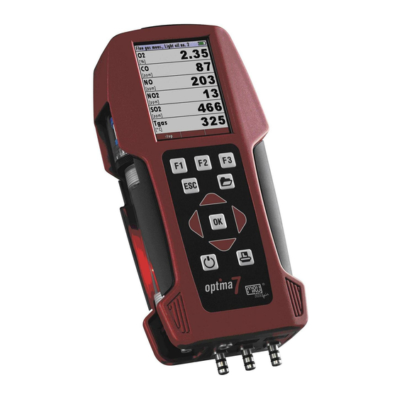
USER MANUAL OPTIMA7 Biogas 7.2. Performing Biogas measurement Measurement start / stop Menu key Store measurement Print display content Back to Measurement menu 7.3. Flue gas measurement (option) Measurement values can be organized on three pages, each page displaying 6 measurement values.
-
Page 35: Setting Co-Limit Value (Only With Flue Gas Measurement)
If in the function key bar «store» is indicated, you can store with the accompanying function key F2 or F3 the measurement in the data memory. The function of the data memory is explained in chapter 8Data Stor- age, Page 40. 35 / 72 MRU GmbH, D-74172 Neckarsulm…
-
Page 36: Printing Measurement Values
USER MANUAL OPTIMA7 Biogas 7.6. Printing measurement values The measurement results can be printed out on the Speedprinter (IR table printer, art. no. 62693) with the printer key. ► You must align the Speedprinter as follows: values that can be seen in the measurement window on all three pages will be printed, dou- ble measurement values will only be printed once.
-
Page 37: Terminate Measurement
► Go to the Measurement menu. ► Select Last measured values. The measured value window with the last measured values appears. ► Press F1. The measurement is continued. 37 / 72 MRU GmbH, D-74172 Neckarsulm…
-
Page 38: Pressure Measurement (Option)
USER MANUAL OPTIMA7 Biogas 7.9. Pressure measurement (Option) Pressure (4 values) is measured and saved to the selected measurement name. The actual measured value is displayed in the middle of the display. The 4 measurement names can be changed as desired.
-
Page 39: Differential Temperature Measurement (Option)
The menu Diff. Temp. Measurement appears. The temperatures T1, T2 and the difference are displayed. NOTE The accuracy of the difference temperature measurement is guaranteed only on use of the MRU temperature sensors. 39 / 72 MRU GmbH, D-74172 Neckarsulm…
-
Page 40: Data Storage
The analyzer can store up to 4,000 different sites. New sites can be added in the analyzer. Modifications can be done using an external PC program e.g. MRU Win. NOTE New sites created in the analyzer will NOT be transferred back to the computer program.
-
Page 41: Calling Up Information About Data Storage
• view all data of the stored sites • create new sites • change date of existing sites • delete sites NOTE New sites created in the analyzer will NOT be transferred to a PC program 41 / 72 MRU GmbH, D-74172 Neckarsulm…
-
Page 42: Create New Site
USER MANUAL OPTIMA7 Biogas Create new site ► Go to the Storage menu. ► Press F2. The menu Sites administration appears. ► Press F1. The menu Modify site appears. ► Press F1 to assign manually a site number to the site.
-
Page 43: View Sites
► Press OK. The menu Search a site appears. You can choose to filter by Site number, by content in Line 2 or for the rest of the other text lines. 43 / 72 MRU GmbH, D-74172 Neckarsulm…
-
Page 44: Changing Sites
USER MANUAL OPTIMA7 Biogas ► Select a line in which you want to search for content. In this example, the search is performed in line 2. ► Press F3. A window appears. ► Enter the desired search term. In this example the search term is John Example.
-
Page 45
► Press OK. A message appears. ► Select continue to delete all sites. ► Select abort to retain all sites. ► Press OK. Depending on the selection, the site is deleted or retained 45 / 72 MRU GmbH, D-74172 Neckarsulm… -
Page 46: Data Transfer Using Sd Card
USER MANUAL OPTIMA7 Biogas 8.4. Data transfer using SD card The data exchange format is CSV. A character-separated values (CSV) file is a simple text format for a database table. Each record in the table is one line of the text file. Each field value of a record is separated from the next by a char- acter.
-
Page 47
However, the analyzer marks the files that have been im- ported successfully. If you try to import a file with the same analyzer that is already in the analyzer you will get a red infor- mation screen. 47 / 72 MRU GmbH, D-74172 Neckarsulm… -
Page 48: Exporting Sites
USER MANUAL OPTIMA7 Biogas Exporting sites ► Go to the Storage menu. ► Select Sites onto SD card. ► Press OK The menu Sites onto SD card appears. ► Press F2. The sites are exported. This function can be used for an analyzer back up or if you wish to supply the analyzer information to a computer program or another analyzer.
-
Page 49: Exporting Combustion Measurements
The created file has the file name “DDMxxxxx.csv“, in which the xxxxx are continu- ing 5-digit numbers with leading zeros. The created file has a column header with the following information: Site number, Date/Time, as well as 4 saved pressure measurements. 49 / 72 MRU GmbH, D-74172 Neckarsulm…
-
Page 50: Measurement In Data Storage
USER MANUAL OPTIMA7 Biogas 8.5. Measurement in Data storage Viewing measurements ► Go to the Storage menu. ► Select View measurements. ► Press OK. The menu View measurements appears. An overview of the number of stored measurements according to the measurement type appears.
-
Page 51: Deleting Measurements
A message appears. Select continue to delete all measurements. Select abort to retain all measurements. ► Press OK. Depending on the selection, the measurement data are deleted or re- tained. 51 / 72 MRU GmbH, D-74172 Neckarsulm…
-
Page 52: Transferring Measurements To Sd-Card (Option)
USER MANUAL OPTIMA7 Biogas Transferring measurements to SD-Card (Option) he analyzer offers the possibility to export all stored measurements to a SD card. ► Go to the Storage menu ► Select Measurements to SD card. ► Press OK. ► Select the desired measurement type.
-
Page 53: Extras / Adjustments
If you enter a wrong pin code you will be exited into the “Extra Menu” again. Please contact MRU GmbH if you need the Pin Code for your analyzer. Press the Enter key if you should have landed in this menu by accident and you will be exited into the “Extra Menu”…
-
Page 54: Default Settings
USER MANUAL OPTIMA7 Biogas 9.2. Default settings The analyzer will be reset to original delivery settings. NOTE With the default setting, all individual settings are lost. ► Go to the Extras menu. ► Select Default settings. ► Press OK. A window appears.
-
Page 55: Service Values
In this menu you will see all ser- vice values of the sensors and also other parameters. In case of a defect contact the MRU service department. The MRU service technician will ask you about these values or he will ask you to send them by fax or email.
-
Page 56: Leak Proof Test
USER MANUAL OPTIMA7 Biogas 9.4. Leak proof test With the leak proof test, the system is checked by the device (incl. the con- densate separator) on undensity. The internal gas pump generates in addi- tion a subpressure which is measured over the built-in draft sensor and is observed for a period of 10 seconds.
-
Page 57: Contents Sd Card
If no undensity is ascertained in these external parts the OPTIMA 7 Combustion Analyzer has to be checked in a service department (worldwide service departments see www.mru.eu) 9.5.Contents SD card ► Go to the menu Extras.
-
Page 58: Contents Analyzer Information
USER MANUAL OPTIMA7 Biogas 9.6. Contents Analyzer information Here you will find information about the analyzer and the installed options. ► Go to the Extras menu. ► Select Device info. The menu Device info appears. ► Press F2. The menu Options list appears.
-
Page 59: Maintenance And Care
• If not used for a longer period of time, charge the battery first. • Charge the battery approximately every 4 weeks. 10.1. Maintenance An annual inspection and, if necessary, calibration of the sensors by an MRU service centre (www.mru.eu) is recommended to maintain their value NOTE Please note that correct operation of the analyzer is only ensured if the sensors are adjusted regularly.
-
Page 60: Appendix
USER MANUAL OPTIMA7 Biogas 11 Appendix 11.1. Technical data General data English Values Operating temperature +5°C … +45 °C / 41 °F … 113 °F Rel. Humidity, non-condensing Storage Temperature -20°C … +50°C / -4°F … 122°F Internal Battery Pack,…
-
Page 61
10% (> 500 ppm) Response Time T90 < 40s Electrochemical Sensor on additional position (depending on configura- tion) Nom. Measuring Range 0 — 500 ppm Overload Range < 2000 ppm Resolution 1 ppm 61 / 72 MRU GmbH, D-74172 Neckarsulm… -
Page 62
USER MANUAL OPTIMA7 Biogas ± 5 ppm / Accuracy abs./reading 5% (0 — 500 ppm) 10% (> 500 ppm) Response Time T90 < 40s Electrochemical Sensor on standard position (depending on configura- tion) Nom. Measuring Range 0 — 2000 ppm Overload Range <5000 ppm… -
Page 63: Analysis And Calculations
Eingabe Querschnittsfläche: Kreis / Rechteck / Quadrat / Form freie Eingabe Einheit cm, m, cm2, mm2, feet2, inch2 Größe 0…60m2 Messbereich 0,1l/s — 6000m3/s Auflösung 11.2. Analysis and calculations Calculated values Air ratio 63 / 72 MRU GmbH, D-74172 Neckarsulm…
-
Page 64
USER MANUAL OPTIMA7 Biogas Measuring Range 1 — 20 Resolution 0,01 Excess Air Measuring Range 0 — 999 % Resolution Dew point Unit °C Measuring Range 0-100 °C Resolution Losses qA Measuring Range 0 — 99,9% Resolution Efficiency Measuring Range… -
Page 65
Available conversions of CO [ppm] related to. on 0% rest O (undiluted) [ppm] related to. on fuel type dependent O reference value [mg/m [mg/kWh] [mg/MJ] [mg/m ] on fuel type depend- ent O reference value 65 / 72 MRU GmbH, D-74172 Neckarsulm… -
Page 66
USER MANUAL OPTIMA7 Biogas Continuously calculated val- Unit Air ratio Dew point [°C] CO/CO2 ratio 66 / 72 MRU GmbH, D-74172 Neckarsulm… -
Page 67: Text Input
Abort the window, changes will NOT be saved 11.4. Asking user for decision The analyzer requires confirmation of the user decision for various functions Select a line Confirm the action Abort the window, changes will NOT be saved 67 / 72 MRU GmbH, D-74172 Neckarsulm…
-
Page 68: Firmware Update
USER MANUAL OPTIMA7 Biogas 11.5. Firmware update Install the new software version in the analyzer ► Go to the Extras menu. ► Select Device info. The menu Device info appears. In the first line the Firmware version appears, for example 1.33.00.
-
Page 69: In Case Of Error
(Check that the SD card is correctly inserted and perform a reset by pressing the ESC and ON keys simultaneously). Where can I get help if the update was not successful? Please contact your responsible sales representative or via email: info@mru.de 69 / 72 MRU GmbH, D-74172 Neckarsulm…
-
Page 70: Troubleshooting
USER MANUAL OPTIMA7 Biogas 11.6. Troubleshooting Troubleshooting the analyzer 1. Effect 2. Error indication 3. Cause 4. Solution Device cannot be LED behind the con- Device does not re- Press ESC and ON simul- switched off by densate separator is taneously! act on any key.
-
Page 71: Troubleshooting Condensate Separator
(white = OK) Sensor failure Brown-black = re- Pump failure newal Wrong measuring values Cover, intermediary unit, Check tightness with plexiglass tube and locking every filter change. pieces are not tightly fixed respectively screwed 71 / 72 MRU GmbH, D-74172 Neckarsulm…
-
Page 72: Declaration Of Conformity
USER MANUAL OPTIMA7 Biogas 12 Declaration of conformity 72 / 72 MRU GmbH, D-74172 Neckarsulm…
- Manuals
- Brands
- mru Manuals
- Measuring Instruments
- Optima 7
- User manual
-
Contents
-
Table of Contents
-
Troubleshooting
-
Bookmarks
Quick Links
Operation manual OPTIMA7
6902EN
1 / 51
MRU GmbH, D-74172 Neckarsulm
Related Manuals for mru Optima 7
Summary of Contents for mru Optima 7
-
Page 1
Operation manual OPTIMA7 6902EN 1 / 51 MRU GmbH, D-74172 Neckarsulm… -
Page 2
Legal notices / Intellectual property rights comments Original user manual © 2018 by MRU No part of this manual my be published in any form (print, fotocopy, electronic media or any other publication form) without a written approval by the publisher. -
Page 3: Table Of Contents
Operation manual OPTIMA7 Content Introduction ……………………. 5 1.1. Intended use ………………….5 1.2. The company MRU GmbH …………….6 1.3. Analyzer details ………………..7 1.4. Packaging ………………….. 7 1.5. Return of hazardous materiales …………..7 1.6. Return of electronic equipment …………..7 Safety ……………………..
-
Page 4
10.4. Using the USB Port ………………. 45 10.5. Technical data ………………..46 Analisis and calculations ………………… 48 10.6. Fuel type list ………………….. 48 10.7. Troubleshooting ………………..49 10.8. Declaration of conformity OPTIMA7 …………51 4 / 51 MRU GmbH, D-74172 Neckarsulm… -
Page 5: Introduction
1000 and UVV = VBG 4 of the professional guilds for fine mechanics and electrical engi- neering. MRU GmbH assures that the analyzer complies to the essential requirements of the legal regulations of the member states of the electro-magnetic compatibility (89/336/EWG).
-
Page 6: The Company Mru Gmbh
(founded in 1984), a medium sized company that specializes in developing, producing and marketing high quality emission monitoring analyzers. MRU GmbH produces a wide range of instruments, from standard analyzers up to tailor made industrial analyzers. MRU GmbH contact details are listed on the previous page.
-
Page 7: Analyzer Details
Hazardous waste must be returned to MRU prepaid. 1.6. Return of electronic equipment MRU GmbH is required to accept the return, for proper disposal, of all analyzers delivered after 13th of August 2005. Analyzers must be returned to MRU prepaid.
-
Page 8: Safety
The explanation of safety notices: • CAUTION HOT – danger of burns and fire hazards from gas extraction probe. Physical harm and property damage can be caused. ► Cool down the probe tube. 8 / 51 MRU GmbH, D-74172 Neckarsulm…
-
Page 9: Ensure Safety
• Don’t carry or store the battery together with sharp objects. • Don’t connect the (+) contact with the (-) contact or connect these to a metal object. • Not obeying the above instructions can cause heat, fire and explosion. 9 / 51 MRU GmbH, D-74172 Neckarsulm…
-
Page 10: Description
OPTIMA7 analyzer measurements of gas, oil and wood fired furnaces. Available options for this and other analyzers can be found on the MRU Homepage or speak to a member of our sales team. Gas schematics diagram…
-
Page 11: The Analyzer
Gas outlet IR-Interface USB-port and charging port SD-card reader Fixing magnets Analyzer feet Handle strip Gas outlet Pressure connector P3 Connector AUX IMORTANT Gas outlet: During measurement the gas outlet must not be covered 11 / 51 MRU GmbH, D-74172 Neckarsulm…
-
Page 12: The Condensate Separator (Water Trap)
During the measurement accumulating condensate is collected in the condensate separa- Remove the condensate separator by pulling it towards you (1) out of the groove of the OPTIMA 7 housing, then pull it downwards (2). • CAUTION Condensate is acidic The condensate from the container can be slight acidic and can cause chemical burn.
-
Page 13: Extraction Probes
1,5 m sampling line and 2,7 m sampling line Probe tube Probe cone ( high grade steel) Triple hose (NBR or Viton) Connector for sample gas measurement Connector for draft measurement Connector for temperature measurement 13 / 51 MRU GmbH, D-74172 Neckarsulm…
-
Page 14: The Display
Abort or return to the menu above ESC Key Jump in between lines, change values Arrow Keys Confirmation key, select a marked menu point OK Key Activates the printer function in the measurement and service window. Printer Key 14 / 51 MRU GmbH, D-74172 Neckarsulm…
-
Page 15: Menu Configuration
Operation manual OPTIMA7 3.6. Menu configuration The OPTIMA 7 organizes all available actions in three main menus: Menu Measurement all tasks for the measurement pro- grams of the analyzer. Here you can select all installed and available measurement programs.
-
Page 16: First Usage
„3 seconds OK key press “ displays Keyboard beeper ON / OFF Keyboard beeper activated or deactivated Power-on logo ON / OFF Logo will be show during power-ON of the ana- lyzer 16 / 51 MRU GmbH, D-74172 Neckarsulm…
-
Page 17: Switch-On Protection
“Zeroing finished, Sensors are ready. Analyzer ready for measurement.” “Reminder! Charge batteries at regular intervals!” “Measurement stopped/started.” 4.3. Switch-ON protection If activated and if ON key is pressed (possibly inadvertently), then the message: „3 seconds OK key press “displays 17 / 51 MRU GmbH, D-74172 Neckarsulm…
-
Page 18: Setting Printer Type And Print Out
In some print outs (adjustment, service …) the info will be printed forever. 4.5. Bluetooth settings The following MRU software can be used: MRU4u (Bluetooth) Available in the Apple App Store and Google Play For iOS communication with PC, tablet or smartphone is additionally…
-
Page 19: Set Time And Date
The CO limit can be defined for each of the 4 measurement programs. Using during the measuring the context menu and you can press the CO limit key – the CO limit can be changed in 100 ppm steps. 19 / 51 MRU GmbH, D-74172 Neckarsulm…
-
Page 20: Select Fuel Types And O Reference
F1 key. Added fuel types have a check mark in front of the fuel type. To each fuel type the parameters are displayed by selecting F3 “O2Ref”. All parameters are displayed read-only except the O” reference value that can be changed 20 / 51 MRU GmbH, D-74172 Neckarsulm…
-
Page 21: User Definable Fuel Types (Only If Combustion Calculation Is On)
Add or remove selected fuel to the pre-selected fuel types Back to the window “Fuel type selection” Modify fuel type parameters Modify fuel type parameters Modify fuel type name Text input see chapter 10.2 Save the new fuel type name 21 / 51 MRU GmbH, D-74172 Neckarsulm…
-
Page 22: Define The Measuring Window
You can choose if you want a core flow search before every measurement or not. This func- tion is only possible in the programs 1 -4. Enabling the core flow search is a global instru- ment setting valid for all programs and therefore described in chapter 4.2 22 / 51 MRU GmbH, D-74172 Neckarsulm…
-
Page 23: Maintenance
Operation manual OPTIMA7 Maintenance The OPTIMA 7 needs to the long value preservation only one very low maintenance need: 5.1. Cleaning Taking good care of your OPTIMA7 will ensure long-term maintenance value: • CAUTION Condensate is acidic The condensate from the container can be slight acidic and can cause chemical burn.
-
Page 24: Preparation For Each Measurement
Preparation for each measurement 6.1. Power supply The analyzer can be used with: • with the internal MRU battery (provided) • with the MRU battery charger (provided) External equipment may only be connected while the analyzer is switched off! 6.2. Auto OFF The instrument is automatically switched off after 60 minutes.
-
Page 25: Operation
If you press the F1 key “Start” in the measurement menu, you will be directed directly into the measurement screen, using the parameters (program and fuel type) that have been se- lected last time the analyzer was used. change be- tween the lines 25 / 51 MRU GmbH, D-74172 Neckarsulm…
-
Page 26: Combustion Test
Temperature will result in the bars moving away from the max. Temperature (1 bar is equivalent to 1°C). Once the right core flow has been achieved, the probe is fixed with the probe cone screw. 26 / 51 MRU GmbH, D-74172 Neckarsulm…
-
Page 27: Measured Value Display
If the draft measurement is disabled it is displayed with “—.-“. The draft measurement can be enabled again by zeroing the draft: F3 key “zero draft”. To indicate that the draft measurement is not continuously available it is displayed in col- our red. 27 / 51 MRU GmbH, D-74172 Neckarsulm…
-
Page 28: Co-Limit (Without Purging)
If the CO value sinks below the CO threshold, then the red CO value becomes again black Starting from this moment the purge pump can be switched off over the menu key again. 28 / 51 MRU GmbH, D-74172 Neckarsulm…
-
Page 29: Test Program
With the ESC key one reaches back in the main menu. • CAUTION HOT – danger of burns and fire hazards from gas extraction probe. Physical harm and property damage can be caused. 1. Cool down the probe tube. 29 / 51 MRU GmbH, D-74172 Neckarsulm…
-
Page 30: Temporary Buffer
7.12. Temporary buffer The OPTIMA 7 gives the possibility to set the momentary values into a temporary buffer during effecting and continuing the measurement. Later on, the values can be brought…
-
Page 31: Printing The Measuring Results
In the main menu “Measurement” select the point “last meas. values”. The last values can be viewed, printed and/or saved. OK F1 Above the F1 key “Start“instead of “Stop” is displayed. Pressing this key will continue the measurement. 31 / 51 MRU GmbH, D-74172 Neckarsulm…
-
Page 32: Pressure Measurement
Note: The accuracy of the difference temperature measurement is guaranteed only on use of the MRU temperature sensors. 7.18. Last measured values offers the possibility to display the last measured values even if they have OPTIMA7 not been stored inside the analyzer.
-
Page 33: Data Storage
The analyzer can store up to 1,000 different sites. New sites can be added in the analyzer. Modifications can be done using an external PC program e.g. MRU Win. Attention: New sites created in the analyzer will NOT be transferred back to the computer program.
-
Page 34
• If only one site is found as a result of the search, this is displayed. If became several sites the total number is found in the header viewed and you can scroll by this found standing with the arrow keys. Page through the sites Menu key: Search site 34 / 51 MRU GmbH, D-74172 Neckarsulm… -
Page 35: New Entry And Change Of Sites
F3 = «store». or F2 8.5. Delete sites You are able to • delete the displayed sites only by selecting the menu entry «F3» = “delete • or delete all sites at the same time 35 / 51 MRU GmbH, D-74172 Neckarsulm…
-
Page 36: Data Transfer Using The Sd Card
Each record in the table is one line of the text file. Each field value of a record is separated from the next by a character. Optima 7 uses a semi-colon ‘;’ as value separator (other implementations use sometimes a comma). Implementations of CSV can often handle field values with embedded line breaks or separator characters by using quotation marks or escape sequences.
-
Page 37
The created file has the file name “DDMxxxxx.csv“, in which the xxxxx are continuing 5 digit num- bers with leading zeros. The created file has a column header with the following information: Site number, Date/Time, as well as 4 saved pressure measurements.. 37 / 51 MRU GmbH, D-74172 Neckarsulm… -
Page 38: Measurement In Data Storage
«search a site» and execute, as de- scribed in the chapter site administration. Delete a measurement You are able to • delete single measurements, while they are displayed – press the key F3 = «delete» . 38 / 51 MRU GmbH, D-74172 Neckarsulm…
-
Page 39
• or delete all measurements of a measuring type. Transfer measurements to the SD card he OPTIMA 7 offers the possibility to export all stored measurements to a SD card. By confirming with the F2 key the data transmission / export on the SD card is started. -
Page 40: Extras / Adjustment
Operation manual OPTIMA7 Extras / Adjustment The OPTIMA 7 is delivered in a standard software configuration which should cover most needs. However, there are many ways to tailor the settings to your individual needs if re- quired. The possibilities are highly flexible and individual adaptable.
-
Page 41: Analyzer And Accessories Leak Test
Operation manual OPTIMA7 In case of a defect contact the MRU service department. The MRU service technician will ask you about these values or he will ask you to send them by fax or email. Jump between the lines Function test gas pump (on / off)
-
Page 42: Contents Sd Card
If of the leak proof test is not passed the probe must be checked including the hosing as well as the condensate separator. If no undensity is ascertained in these external parts the OPTIMA 7 Combustion Analyzer has to be checked in a service department (worldwide service departments see www.mru.eu)
-
Page 43: Contents Analyzer Information
Here you will find information about the analyzer and the installed options. Press the F2-key to see the installed options. With the F1-key you get information about the date of the last 7 service procedures 43 / 51 MRU GmbH, D-74172 Neckarsulm…
-
Page 44: Appendix
Selected letter or number will over write the current letter or num- Abort the window, changes will NOT be saved 10.2. Asking user for a decision The OPTIMA 7 will ask you now and then to confirm the action that will be taken. Select a line Confirm the action…
-
Page 45: Firmware Update
10.4. Using the USB Port This port is used for data transfer from your analyzer to your PC / Laptop using the MRU Online View (Version 2.XX). The first time you want to use your analyzer for data transfer to your PC or laptop, you have to “mate”…
-
Page 46: Technical Data
0 – 2.000 ppm, overload up to 5.000 ppm*** Accuracy ± 10 ppm or** 5 % of the measured value up to 2.000 ppm or** 10 % of the measured value up to 5.000 ppm Reaction time T90* ≤ 40 sec 46 / 51 MRU GmbH, D-74172 Neckarsulm…
-
Page 47
244 x 113 x 54 mm / 4.3” x 8.8” x 2.04” * = typical sensor value, ** whichever is larger, ***only for SHORT-TERM measurement Technical changes possible Rev date: 20180814 at any time! 47 / 51 MRU GmbH, D-74172 Neckarsulm… -
Page 48: Analisis And Calculations
The calculations of efficiency and exhaust losses are performed using Siegert’s formula. For further information please contact MRU GmbH. (www.mru.eu) 10.6. Fuel type list Fuel types for different countries can be obtained from MRU GmbH: Web page: www.mru.eu 48 / 51…
-
Page 49: Troubleshooting
(loose connection), re- line, formation of move condensate condensate at the from the probe tip. probe tip. 49 / 51 MRU GmbH, D-74172 Neckarsulm…
-
Page 50
(white = OK) Sensor failure Brown-black = renewal Pump failure Wrong measuring values Cover, intermediary unit, Check tightness with every plexiglass tube and locking filter change. pieces are not tightly fixed respectively screwed 50 / 51 MRU GmbH, D-74172 Neckarsulm… -
Page 51: Declaration Of Conformity Optima7
Operation manual OPTIMA7 10.8. Declaration of conformity OPTIMA7 51 / 51 MRU GmbH, D-74172 Neckarsulm…
-
Газоанализатор Optima 7
/images/all/3/3001/big/img_5.jpg
jijijij

-
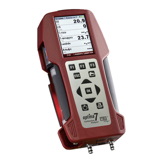
Газоанализатор Optima 7 в кейсе для переноски
/images/all/3/3001/big/img_14.jpg
Газоанализатор Optima 7 в кейсе для переноски
-
Газоанализатор Optima 7
/images/all/3/3001/big/img_16.jpg
1
-
Газоанализатор Optima 7 в сумке для переноски
/images/all/3/3001/big/img_18.jpg
1


Просьба уточнять актуальность цены у менеджеров. Стоимость указана с учетом НДС. Оплата производится по безналичному расчету.
Внимание! Счета выставляются при сумме заказа от 3000 руб. Мы работаем как с юридическими, так и с физическими лицами.
Осуществляем доставку по России, Казахстану, Беларуси и странам таможенного союза курьерскими службами и транспортными компаниями.

ОПИСАНИЕ
ОТЗЫВЫ
ВОПРОСЫ
Газоанализатор Optima7
Тип оборудования: Газоанализатор, анализатор дымовых газов, анализатор давления, скорости воздуха.
Производитель: MRU, Германия
Серия: Optima7
Модель: Optima7
Описание: прибор для настройки и регулировки газовых и жидкотопливных горелок, котлов.
Гарантия на газоанализатор Optima7: 12 мес.
Газоанализатор Optima7 внесен в Государственный реестр средств измерений РФ
Назначение прибора:
Ручной, компактный, высокоточный газоанализатор для промышленности Optima7 предназначен для точной настройки и регулировки газовых и жидкотопливных горелок, наладки конденсационных котлов, а также экологических замерах.
Особенности газоанализатора Optima7:
-
Измерение 1, 2, 3, 4 или до 7 газов одновременно(O2, CO, NO, NO2, SO2, CO2, H2S)
-
Измерение дифференциального давления
-
Измерение скорости газового потока (опция)
-
Погрешность по NO — 5% от измеренного значения
-
Погрешность по NO2 — 5ппм
-
Противоударный корпус со встроенным держателем на ремень и магнитом
-
Дополнительный насос для продувки сенсора СО (опция)
-
Защитное отключение СО (программируется Пользователем)
-
Подходит для всех типов горелок
-
Компактный и легкий, простой в работе
-
Различные длины и материал зондов
-
Русская версия экранного меню прибора
-
Цветной 8-ми строчный дисплей со встроенной подсветкой
-
ИК-интерфейс для передачи данных на портативный принтер
-
Встроенная память на 100 измерений
-
Интерфейс miniUSB для передачи данных на ПК
-
Работа от встроенных аккумуляторов или от сети 220 В (в комплекте)
-
Уловитель конденсата с фильтром (в комплекте)
-
Зонд температуры окружающего воздуха (опция)
-
Термобокс от -15 градусов (опция)
-
Измерение тяги/разрежения
Технические характеристики газоанализатора Optima7:
|
Каналы измерения |
|
|
O2 |
|
|
Диапазон измерения |
0 — 21,0 об. % |
|
Погрешность измерения |
± 0,2 об.% . во всем диапазоне |
|
CO (с компенсацией H2 ) |
|
|
Диапазон измерения |
0 — 4.000 ppm, возможно до 10.000 ppm |
|
Погрешность измерения |
± 20 ppm или 5 % от измеренного значения ≤ 4.000 ppm 10 % от измеренного значения > 4.000 ppm |
|
CO высокое (опция # 61506) |
|
|
Диапазон измерения |
0 — 4.000 ppm, возможно до 20.000 ppm |
|
Погрешность измерения |
± 100 ppm или 5 % от измеренного значения ≤ 4.000 ppm 10 % от измеренного значения > 4.000 ppm |
|
NO (опция # 61505) |
|
|
Диапазон измерения |
0 — 1.000 ppm, возможно до 5.000 ppm |
|
Погрешность измерения |
± 5 ppm или 5 % от измеренного значения ≤ 1.000 ppm 10 % от измеренного значения > 1.000 ppm |
|
NO2 (опция # 61507) |
|
|
Диапазон измерения |
0 — 200 ppm, возможно до 1.000 ppm |
|
Погрешность измерения |
± 5 ppm или 5 % от измеренного значения ≤ 200 ppm 10 % от измеренного значения > 200 ppm |
|
SO2 (опция # 61508) |
|
|
Диапазон измерения |
0 — 2.000 ppm, возможно до 5.000 ppm |
|
Погрешность измерения |
± 10 ppm или 5 % от измеренного значения ≤ 2000 ppm 10 % от измеренного значения > 2000 ppm |
|
Температура газа TA |
|
|
Диапазон измерения |
0 — 600 °C при использовании стандартной газозаборной трубки |
|
Погрешность измерения |
± 2 °C ≤ 200 °C 1 % от измеренного значения > 200 °C |
|
Температура воздуха TL |
|
|
Диапазон измерения |
0 — 100 °C |
|
Погрешность измерения |
± 1 °C |
|
Давление/Разрежение |
|
|
Диапазон измерения |
± 100 гПа |
|
Погрешность измерения |
± 0,03 гПа или 1% от измеренного значения |
|
Дифференциальное давление (опция # 61509) |
|
|
Диапазон измерения |
± 100 гПа |
|
Погрешность измерения |
± 0,03 гПа или 1% от измеренного значения |
|
Скорость газового потока (опция # 61509) |
|
|
Диапазон измерения |
1 м/сек до 100 м/сек |
|
Погрешность |
± 1 м/сек или 1 % от измеренного значения |
|
Расчетные параметры (Зависит от вида топлива) |
|
|
CO2 |
|
|
Диапазон измерения |
0 — CO2 макс |
|
Погрешность измерения |
± 0,3 об.% во всем диапазоне. |
|
Точка росы |
°C |
|
Потери тепла qA |
0 — 99,9 % |
|
Эффективность |
0 — 120 % |
|
Размерность |
мг/Нм3,приведенный к O2, мг/КВтч, NOx как мг/Нм3 NO2 |
|
Общие данные |
|
|
Рабочая температура |
+ 5 — + 45 °C, максимально 95 % ОВ, без конденсации |
|
Температура хранения |
— 20 — + 50 °C |
|
Электропитание |
4 аккумулятора NiMh (тип АА), на 8 часов непрерывной работы, сетевой адаптер для зарядки аккумуляторов 90 — 260В / 6 — 9В |
|
Масса |
не более. 1 кг. |
|
Габариты |
(Ш x Д x В) 80 x 210 x 55 мм |
Комплект поставки газоанализатора Optima7:
- Газоанализатор Optima7
-
Пластиковый кейс для прибора и принадлежностей
-
Руководство по эксплуатации
*Технические характеристики и комплект поставки оборудования могут быть изменены производителем без предварительного уведомления.
Дополнительную информацию по ценам на газоанализаторы и их характеристикам можно получить, обратившись к нашим специалистам, по телефонам, указанным в разделе
«контакты«.
Доставляем оборудование для контроля параметров окружающей среды по всей России курьерскими службами и транспортными компаниями.
| Владимир: Цена газоанализатора Optima 7 |
Спрашивает: Осман:
Здравствуйте. Скажите цену на optima 7 и комплекттацию
Спрашивает: Владимир:
Сообщите цену Optima 7
Спрашивает: Bolatbek:
Можно ли вашим прибором Optima 7 замерять CH если да то как?
Спрашивает: Алексей:
Здравствуйте. Подскажите, как установить в газоанализатор Optima 7 встроенный сенсор O2 long life? До этого стоял стандартный. Спасибо
|
Сертификаты
|
|
|
|
|
|
ПОХОЖИЕ ТОВАРЫ |

- Описание
- Особенности
- Комплектация
- Технические характеристики
- Поддержка
- Отзывы (0)
Optima 7 — Газоанализатор компактный мультигазовый с первичной поверкой
Многоцелевой анализатор MRU Optima 7 (Оптима 7) для наладки и контроля котлов и турбин, а также экологического мониторинга выбросов промышленных объектов. Эргономичный, тонкий, легкий корпус удобно помещается в руке, а встроенные магниты позволяют прикрепить измерительный блок к металлическим поверхностям, что освобождает Ваши руки при проведении измерений. Большой цветной дисплей с яркой подсветкой позволяет считывать показания на большом расстоянии и при плохом освещении. Передача информации на принтер осуществляется с помощью ИК-порта, для подключения прибора к компьютеру используется мини-USB. Хранение данных на SD-карте памяти объемом 2Гб.
Особенности прибора Optima 7:
- Одновременно измеряет 7 компонентов
- Удобный тонкий корпус с встроенными магнитами
- Яркий цветной дисплей 3,5” с подсветкой
- Мини-USB для подключения к ПК
- ИК-порт для передачи на скоростной термопринтер
- Встроенный конденсатосборник с PTFE фильтром и подсветкой
- Программируемые функциональные кнопки
- Коннекторы из нержавеющей стали
- Внесен в Гос. Реестр СИ РФ
Комплект поставки измерительного оборудования Optima 7:
- Сенсор O2
- Датчик давления
- Блок питания
- Аккумулятор
- Встроенная память
- Разъем mini-USB
Технические характеристики газоанализатора Optima 7:
| Виды топлива | Природный газ, дизель, сжиженный газ, мазут, гранулы, дрова, биодизель, и «индивидуальные» | |
| Измеряемые параметры | Диапазон измерения | Погрешность |
| Электрохимические сенсоры | ||
| Кислород O2 | (0-21,0)% | ±0,2% |
| Оксид углерода CO с H2 компенсацией | (0… 400) млн-1 (св. 400… 4000)млн-1 (св. 4000… 10000)млн-1 |
±20 млн-1 ±5% ±10% |
| Оксид углерода CO низкий
(специальная программа и калибровка) |
(0… 100) млн-1 (св. 100… 300) млн-1 (св. 300… 400) млн-1 (св. 400… 4000) млн-1 (св. 4000… 10000) млн-1 |
±5 млн-1 ±5% ±20 млн-1 ±5% ±10% |
| Оксид углерода CO высокий | (0… 800) млн-1 (св. 800… 20000) млн-1 |
±40 млн-1 ±5% |
| Оксид углерода CO очень высокий | (0… 0,4)% (св. 0,4… 10)% |
±0,02% ±5% |
| Оксид азота NO | (0… 100) млн-1 (св. 100… 4000) млн-1 |
±10 млн-1 ±10% |
| Оксид азота NO низкий (специальная программа и калибровка) | (0… 50) млн-1 (св. 50… 300) млн-1 (св. 300… 4000) млн-1 |
±5 млн-1 ±10% ±10% |
| Диоксид азота NO2 | (0… 50) млн-1 (св. 50… 500) млн-1 |
±5 млн-1 ±10% |
| Диоксид серы SO2 | (0… 100) млн-1 (св. 100… 4000) млн-1 |
±10 млн-1 ±10% |
| Сероводород H2S | (0… 100) млн-1 (св. 100… 300) млн-1 |
±10 млн-1 ±10% |
| Инфракрасные сенсоры | ||
| Диоксид углерода CO2 | (0… 5)% (0… 8)% (0… 20)% |
±0,2% ±0,2% ±0,5% (0… 10)% ±5% (св. 10… 20)% |
| Диоксид углерода CO2 | (0… 30)% | ±0,5% (0… 10)% ±5% (св. 10… 30)% |
| Диоксид углерода CO2 | (0… 50)% | ±0,5% (0… 10)% ±5% (св. 10… 50)% |
| Оксид углерода CO | (0… 30)% | ±0,05% (0… 1,0)% ±5% (св. 1,0… 30)% |
| Метан CH4 | (0… 20)% | ±0,02% (0… 0,4)% ±5% (св. 0,4… 20) |
| Температура газа | 0… 650 °C (нержавеющая сталь) 0… 1 000 °C (сплав инконель) |
±2°C (0… 200°C); ±1% (0… 650°C) ±2°C (0… 200°C); ±1% (200… 1000°C) |
| Температура воздуха | 0… 100 °C | ±1°C |
| Дифференциальное давление | – 100… 100 гПа | ±0,02гПа (-2… 2гПа) ±1% (-100… 2гПа) ±1% (2… 100гПа) |
| Расчетные параметры (зависят от вида топлива) | ||
| Диоксид углерода CO2 | 0… 20% | ±0,3% об. (абс) |
| Потери qA | 0… 99,9 % | |
| Эффективность η | 0… 120 % | |
| Избыток воздуха λ | 1… 9,99% | |
| Теплотехнические параметры | Расчет для вида топлива ( в т.ч.. индивидуальных): CO2, избыток воздуха λ, потери, эффективность сгорания, точка росы, соотношение CO/ CO2 | |
| Расчет выбросов | Мг/Нм3, NOx как мг/м3 NO2 истинное значение NOx=NO+NO2, с учетом 02 нормативное (корректируется пользователем) | |
| Продувка для защиты сенсора CO (опция) при помощи 2-го насоса* | ||
| Основные параметры: | ||
| Рабочая температура | 5… 45°C, при ОВ не более 95%, без образования конденсата | |
| Температура хранения | -20 … 50°C | |
| Применение | Неагрессивная среда, без большого содержания пыли, не пожаро-взрывоопасные зоны | |
| Электропитание | Встроенные аккумуляторы: Li-ion на 15 часов работы или NiMH на 6 часов работы От внешнего источника питания 220В или от USB порта ПК |
|
| Класс защиты | IP20 | |
| Вес, кг, не более | 0,9 с термочехлом 1,2 с термобоксом 2,7 |
|
| Габариты, мм, не более | 244 х 113 х 54 мм |
*возможна при отсутствии ИК-сенсоров
Назначение
Описание
Программное обеспечение
Технические характеристики
Знак утверждения типа
Поверка
Сведения о методах измерений
Нормативные документы
Назначение
Газоанализаторы Optima 7 (далее — газоанализаторы) предназначены для измерения объемной доли O2, СО, NO, NO2, SO2, H2S, С02, СН4, а также, параметров газовых сред в газоходах при контроле производственных процессов: температуры, давления.
Описание
Принцип действия газоанализаторов основан на непрерывном и селективном измерении электрохимическими (для газов O2, СО, NO, NO2, SO2, H2S) и инфракрасными (для газов СО, С02, СН4) сенсорами анализируемых компонентов в потоке проходящего газа. Пробы газа для анализа отбирают при помощи зонда и встроенного в анализатор мембранного насоса. Анализируемый газ проходит по шлангу через сборник конденсата и фильтр в измерительный сенсор. Общее число установленных сенсоров для измерения газов может быть от одного до семи. Если в анализаторе присутствует более одного канала измерений СО или NO, с разными диапазонами измерений, переключение с меньшего на больший диапазон, происходит автоматически.
Газоанализаторы полностью автоматизированы. Встроенный микропроцессор управляет процессом измерений. Перед каждым измерением проводится автоматическая диагностика газоанализаторов, продувка сенсоров воздухом и установка нулевых показаний. Возможно автоматическое переключение сенсоров при превышении заданного диапазона массовых концентраций оксида углерода и оксида азота. Предусмотрено также автоматическое отключение приборов, если температура окружающей среды не соответствует заданной.
Газоанализаторы имеют 2 канала измерений температуры с термоэлектрическими преобразователями с номинальной статической характеристикой преобразования (НСХ) типа «К» по МЭК 60584-1 (ГОСТ Р 8.585-2001), принцип действия которых основан на термоэлектрическом эффекте — генерировании термоэлектродвижущей силы, возникающей из-за разности температур между соединениями различных металлов или сплавов, образующих часть одной и той же цепи. Газоанализаторы позволяют измерять избыточное и абсолютное давление (разрежение), а также разность давлений газа в неагрессивных средах. Для этого газоанализаторы снабжены тензоре-зистивными первичными сенсорами и электронной схемой.
При появлении на входах давления (разности давлений) происходит его преобразование в электрический сигнал. Значение этого сигнала пропорционально измеряемому давлению.
Газоанализаторы имеют крупный цветной графический дисплей с функцией «zoom», что позволяет индицировать на одной странице 6 параметров в обычном размере или два параметра в крупном размере. Последовательность и размер индикации на «страницах» дисплея, а также количество «страниц» индикации настраивается Пользователем.
Программное обеспечение (ПО) позволяет на основании измеренных значений состава и температуры анализируемого газа, рассчитать эффективность и потери при сжигании топлива, содержание диоксида углерода (при отсутствии соответствующего сенсора), температуру точки росы, коэффициент избытка воздуха X. Полученные результаты выводятся на дисплей, и внешний принтер.
Общий вид газоанализатора Optima 7 представлен на рисунке 1.
Пломбирование газоанализатора Optima 7 не предусмотрено.
Рисунок 1 — Общий вид газоанализатора Optima 7.
Программное обеспечение
Для идентификации ПО используется файловый менеджер Total Commander.
Обработка метрологических данных происходит на основе жестко определенного алгоритма без возможности изменения.
Метрологически незначимая часть, состоит из ПО, которое используется для обеспечения наилучшей наглядности отображения информации.
Защита ПО осуществляется посредством записи защитного бита при программировании микропроцессора в процессе производства газоанализаторов. Защитный бит запрещает чтение кода микропрограммы, поэтому модификация программного обеспечения (умышленная или неумышленная) невозможна. Снять защитный бит можно только при полной очистке памяти микропроцессора вместе с программой находящейся в его памяти.
Уровень защиты программного обеспечения «высокий» в соответствии с Р 50.2.077-2014.
Программное обеспечение не влияет на метрологические характеристики.
Таблица 1 — Идентификационные данные программного обеспечения
|
Идентификационные данные (признаки) |
Значение |
|
|
Аппаратное ПО |
ПО для перепрограммирования анализатора |
|
|
Идентификационное наименование ПО |
OPT7.mastersoft |
OPT7.servicesoft |
|
Номер версии (идентификационный номер) ПО |
ПО 1.10.10 |
V1.11.03 |
|
Цифровой идентификатор ПО |
1156211 |
0202А41 |
|
Алгоритм вычисления цифрового идентификатора ПО |
CRC32 |
Таблица 2 — Диапазон измерений и пределы допускаемой основной погрешности
|
Диапазон измерений объемной доли |
Пределы допускаемой погрешности* |
|
|
абсолютной, об. доля |
относительной, % |
|
|
Канал О2 |
||
|
от 0 до 21,0 % |
±0,2 % |
— |
|
Канал CO низкий |
||
|
от 0 до 100 млн-1 св. 100 до 300 млн-1 включ. |
±5 млн-1 |
±5 |
|
Канал CO |
||
|
от 0 до 400 млн-1 св. 400 до 4000 млн-1 включ. св. 4000 до 10000 млн-1 включ |
±20 млн-1 |
±5 ±10 |
|
Канал CO при установленном канале CO низкий |
||
|
св. 300 до 400 млн-1 включ. св. 400 до 4000 млн-1 включ. св. 4000 до 10000 млн-1 включ. |
±20 млн-1 |
±5 ±10 |
|
Канал CO высокий |
||
|
от 0 до 800 млн-1 св. 800 до 20000 млн-1 включ. |
±40 млн-1 |
±5 |
|
Канал CO очень высокий |
||
|
от 0 до 0,4 % св. 0,4 до 10 % включ. |
±0,02 % |
±10 |
|
Канал NO низкий |
||
|
от 0 до 50 млн-1 св. 50 до 300 млн-1 включ. |
±5 млн-1 |
±10 |
|
Канал NO |
||
|
от 0 до 100) млн-1 св.100 до 4000 млн-1 включ. |
±10 млн-1 |
±10 |
|
Канал NO при установленном канале NO низкий |
||
|
св. 300 до 4000 млн-1 включ. |
±10 |
|
|
Канал |
NO2 (до 500 млн-1) |
|
|
от 0 до 50 млн-1 св. 50 до 500 млн-1 включ. |
±5 млн-1 |
±10 |
|
Канал SO2 |
||
|
0 до 100 млн-1 св. 100 до 4000 млн-1 включ. |
±10 млн-1 |
±10 |
|
Канал H2S (до 300 млн-1) |
||
|
от 0 до 100 млн-1 св. 100 до 300 млн-1 включ. |
±10 млн-1 |
±10 |
|
Канал СО2 инфракрасный |
||
|
от 0 до 5 % |
±0,2 % |
— |
|
Канал СО2 инфракрасный |
||
|
от 0 до 8 % |
±0,2 % |
— |
|
Канал СО2 инфракрасный |
||
|
от 0 до 10 % св. 10 до 20 % включ. |
±0,5 % |
±5 |
Продолжение таблицы 2
|
Диапазон измерений объемной доли |
Пределы допускаемой погрешности* |
|
|
абсолютной, об. доля |
относительной, % |
|
|
Канал СО2 инфракрасный |
||
|
от 0 до 10 % св. 10 до 30 % включ. |
±0,5 % |
±5 |
|
Канал СО2 инфракрасный |
||
|
от 0 до 10 % св. 10 до 50 % включ. |
±0,5 % |
±5 |
|
Канал CO инфракрасный |
||
|
от 0 до 1,0 % св. 1,0 до 30 % включ. |
±0,05 % |
±5 |
|
Канал СН4 инфракрасный |
||
|
от 0 до 0,4 % св. 0,4 до 20 % включ. |
±0,02 % |
±5 |
|
Примечание: *при температуре окружающей среды (20 ± 5) °С. |
Таблица 3 — Диапазон измерений температуры и пределы допускаемой основной погрешности каналов измерения температуры_
|
Диапазон измерений температуры |
Пределы допускаемой погрешности* |
|
|
абсолютной |
относительной,% |
|
|
зонд из нержавеющей стали (термоэлектрический преобразователь с НСХ типа «К» для |
||
|
измерения температуры газа, диапазон измерений: от 0 до 650°С) |
||
|
от 0 до 200 |
±2 |
|
|
свыше 200 до 650 |
±1 |
|
|
зонд из сплава INCONEL (термоэлектрический преобразователь с НСХ типа «К» для |
||
|
измерения температуры газа, диапазон измерений: от 0 до 1000°С) |
||
|
от 0 до 200 |
±2 |
|
|
свыше 200 до 1000 |
±1 |
|
|
зонд из пластика с открытым ЧЭ (термоэлектрический преобразователь с НСХ типа «К» для |
||
|
измерений температуры воздуха, диапазон измерений: от 0 до 100°С) |
||
|
от 0 до 100 оС |
±1 |
|
|
Примечание: *при температуре окружающей среды (20 ± 5) °С |
Таблица 4 — Диапазон измерений и пределы допускаемой основной погрешности каналов измерения давления_
|
Диапазон измерений дифференциального давления, избыточного давления, вакуумметрического давления |
Пределы допускаемой погрешности* |
|
|
абсолютной |
относительной,% |
|
|
от минус 2 гПа до 2 гПа от минус 100 гПа до минус 2 гПа от 2 гПа до 100 гПа |
±0,02 гПа |
±1 1 |
|
Примечание: *при температуре окружающей среды (20 ± 5) °С. |
Таблица 5 — Пределы допускаемой дополнительной погрешности от изменения температуры окружающей среды в диапазоне (5.. .40) °С в долях основной погрешности на каждые 10 °С
|
Канал измерения |
Значение |
|
Канал О2 (21 %) |
±0,3 |
|
Канал CO |
±0,2 |
|
Канал NO |
±0,3 |
|
Канал NO2 |
±0,3 |
|
Канал SO2 |
±0,5 |
|
Канал H2S |
±0,5 |
|
Канал СО2 |
±0,3 |
|
Канал СН4 инфракрасный |
±0,5 |
|
Канал измерения температуры газа (воздуха) |
±0,1 |
Технические характеристики
|
Наименование характеристики |
Значение |
|
Параметры электрического питания: — напряжение переменного тока |
встроенный аккумулятор, от внешнего источника 220 В или от USB порта компьютера |
|
Потребляемая мощность (с термобоксом), Вт, не более |
7 (18) |
|
Температура хранения, °С |
от -20 до +50 |
|
Габаритные размеры (с термобоксом), мм, не более: |
|
|
— длина — ширина — высота |
244 (292) 113 (150) 54 (б8) |
|
Масса газоанализатора, кг, не более Масса газоанализатора с термочехлом, кг, не более Масса газоанализатора с термобоксом с обогревом, кг, не более |
0,9 1,2 2,7 |
|
Условия эксплуатации: |
|
|
— температура окружающей среды, °С: |
от +5 до +45 от -15 до +40 (с термочехлом) от -30 до +40 (с термобоксом с обогревом) |
|
— относительная влажность воздуха, % |
до 95, без образования конденсата |
|
Класс защиты |
IP 20 (с термобоксом IP 21) |
|
Наработка на отказ, ч, не менее |
8000 |
Знак утверждения типа
наносится на шильдик с индивидуальным номером прибора и может дублироваться на лицевой панели прибора, а также, на титульный лист Руководства по эксплуатации газоанализатора типографским способом.
Таблица 7 — Комплектность средства измерения
|
Наименование характеристики |
Обозначение |
Количество |
|
Газоанализатор** с измерительными сенсорами O2, СО, NO, NO2, SO2, H2S, ТО2, СН4 |
Optima 7 |
по заказу |
|
Внешние зонды и соединительные шнуры |
— |
по заказу |
|
Футляр для хранения и транспортировки |
— |
1 шт. |
|
Руководство по эксплуатации |
— |
1 экз. |
|
Методика поверки |
МП 48157-11 |
1 экз. |
|
Примечание. ** — в зависимости от заказанной комплектации. |
Поверка
осуществляется по документу МП 48157-11 «Инструкция. Газоанализаторы «Optima 7″. Методика поверки», утвержденному ГЦИ СИ ФГУП «ВНИИМС» 15 сентября 2011 г.
Основные средства поверки:
— ГСО 10530-2014;
— ГСО 10531-2014;
— ГСО 10537-2014;
— ГСО 10546-2014;
— генератор газовых смесей ГГС модификация ГГС-03-03 (рег. № 62151-15).
Допускается применение аналогичных средств поверки, обеспечивающих определение
метрологических характеристик, поверяемых СИ с требуемой точностью.
Знак поверки наносится на свидетельство о поверке.
Сведения о методах измерений
приведены в эксплуатационном документе.
Нормативные документы
ГОСТ 8.558-2009 ГСИ. Государственная поверочная схема для средств измерений температур»
ГОСТ 8.187-76 ГСИ. Государственный специальный эталон и общесоюзная поверочная схема для средств измерений разности давлений до 4-104 Па
Приказ Росстандарта от 14.12.2018 г. № 2664 Государственная поверочная схема для средств измерений содержания компонентов в газовых и газоконденсатных средах Техническая документация фирмы-изготовителя «MRU GmbH», Германия