//Руководство по эксплуатации эскалатора OTIS XO 21NR
//Руководство по эксплуатации, пассажирский ЩЛЗ, 2017 г.
//Руководство по эксплуатации Могилевлифтмаш, 1998 г.
//Руководство по эксплуатации лифта Otis Европа-2000 серии Z
//Руководство по эксплуатации лифта Otis GeN2 Premier
//Руководство по эксплуатации лифта Otis GeN2 MRL
//Руководство по эксплуатации лифта Otis GeN2 Comfort
//Руководство по эксплуатации лифта Otis 2000, 2017 г.
//Руководство по эксплуатации лифта Otis 1000 R УТВ
//Руководство по эксплуатации лифта KLEEMANN Line 2000
//Руководство по эксплуатации КМЗ 630 кг, 1 м/с, 1996 г.
//Руководство по эксплуатации, грузовой ЩЛЗ 2013 г.
//Инструкция по монтажу АО «Уральский лифтостроительный завод» 1993 г. (pdf)
//Инструкция по эксплуатации СПУЛ (pdf)
//Руководство по эксплуатации лифта Otis HEBA (pdf)
-
Contents
-
Table of Contents
-
Bookmarks
Quick Links
Model OI-7032
32-Channel
_____________________________________
Operation Manual
Revision 2.5w
_______________________________________________________________________________________
___________________________________________________________
Summary of Contents for OTIS GEN2 OI-7032
-
Page 1
Model OI-7032 32-Channel _____________________________________ Operation Manual Revision 2.5w _______________________________________________________________________________________ ___________________________________________________________… -
Page 2: Product Overview
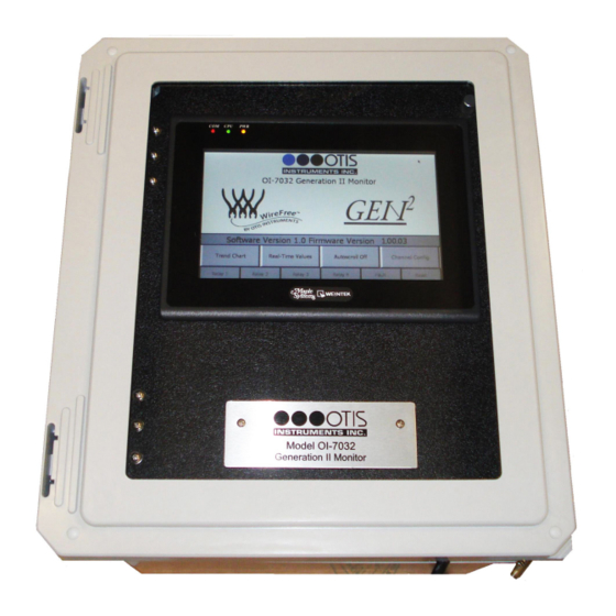
Product Overview The Otis Instruments, Inc. GenII OI-7032 (32-Channel) is a Hybrid Monitor that supports up to 32 WireFree sensor units, and up to four 4-20mA input sensors (when only 28 channels are setup as WireFree). The OI-7032 is backward compatible with GenI WireFree sensor units, and also supports GenII Wirefree sensor units (configurable).
-
Page 3: Table Of Contents
Table of Contents Product Overview……………………….2 Introduction…………………………5 Warnings…………………………6 Complete System Diagrams……………………7 Front Panel…………………………….7 Internal Diagram…………………………..8 Terminal Board……………………………..9 Touchscreen (Front)……………………………10 Touchscreen (Back)…………………………..10 AC (Delta) Power Supply…………………………11 Internal Diagram – As Wired from the Factory………………….12 Internal Diagram – Completely Wired……………………..13 Wiring Configurations……………………..14 DC Power-in (24 Volts DC (nominal;…
-
Page 4
VIEW Modbus Output Settings: Baud Rate……………………71 VIEW Radio Settings: Radio Timeout……………………..72 VIEW Gen II Radio Settings: Network ID……………………72 VIEW Gen II Radio Settings: Primary or Secondary Monitor………………73 VIEW OI-7032 Reset to Factory Default……………………73 VIEW Relay Settings: Relays 1-4 (Failsafe)……………………74 VIEW Relay Settings: Fault Terminal……………………..74 VIEW Relay Settings: Fault Relay Assign…………………… -
Page 5: Introduction
Introduction This document is an Operation Manual containing diagrams and step-by-step instruction for proper operation of the Otis Instruments, Inc. GenII OI-7032. This document should be read before initial operation of the product. Should a question arise during the use of the product, this document will serve as a first reference for consultation.
-
Page 6: Warnings
-20 to 122 degrees Fahrenheit. If the OI-7032 is at risk of being exposed to temperatures that are outside the previously stated range, DO NOT install the device in that location. For applications in areas with the potential of reaching extreme temperatures, Otis Instruments recommends using the OI-7032 indoors only (in a temperature-controlled environment).
-
Page 7: Complete System Diagrams
Complete System Diagrams The following diagrams should be consulted for identification of Panels, Boards, and any other system component that may be referred to in this Operation Manual. Front Panel…
-
Page 8: Internal Diagram
Internal Diagram…
-
Page 9: Terminal Board
Terminal Board…
-
Page 10: Touchscreen (Front)
Touchscreen (Front) Touchscreen (Back)
-
Page 11: Ac (Delta) Power Supply
AC (Delta) Power Supply…
-
Page 12: Internal Diagram — As Wired From The Factory
Internal Diagram – As Wired from the Factory…
-
Page 13: Internal Diagram — Completely Wired
Internal Diagram – Completely Wired…
-
Page 14: Wiring Configurations
Please consult a solar panel manufacture for specific details. Otis Instruments, Inc. may also be contacted to provide guidance and recommendations.
-
Page 15
DC Power-in (24 Volts DC (nominal; 22-26 Volts DC)) cont… 1. Open the enclosure box to expose the Front Panel. 2. Unscrew the two thumb-screws on the Front Panel. 3. Open the Front Panel so that the Terminal Board is exposed. -
Page 16
DC Power-in (24 Volts DC (nominal; 22-26 Volts DC)) cont… 4. Locate the Power Terminal (on the lower right side of the Terminal Board). 5. Connect the DC Power Supply live wire (red) to the terminal marked “+12-35 VDC”. 6. Connect the DC Power Supply Ground wire (black) to the terminal marked “GND”. 7. -
Page 17: Ac Power Supply Connection
For AC Power applications, the Delta Power Supply located below the Terminal Board should be used. NOTE: The unit will be wired for the power-type that is requested by the purchaser when shipped from Otis Instruments, Inc. 1. Open the enclosure box to expose the Front Panel.
-
Page 18
AC Power Supply Connection cont… 4. Connect a positive (red) wire to the Power Terminal terminal labeled “+12-35 VDC” on the Terminal Board. 5. Connect the other end of that same positive (red) wire from the Terminal Board to the terminal labeled “+V”… -
Page 19: Touchscreen Power Connection
Touchscreen Power Connection NOTE: The Touchscreen power connection will be pre-wired for use when the unit is shipped from Otis Instruments, Inc. 1. Open the enclosure box to expose the Front Panel. 2. Unscrew the two thumb-screws on the Front Panel.
-
Page 20
Touchscreen Power Connection cont… 4. Locate the Touchscreen’s Power Terminal. 5. Connect the positive DC Supply wire (red) to the terminal labeled “+”. 6. Connect the negative DC Supply wire (black) to the terminal labeled “-” 7. Connect an earth ground wire (green) to the ground terminal. 8. -
Page 21
Touchscreen Power Connection cont… 9. Connect the positive DC Supply wire (red) to the terminal labeled “12-32 VDC” on the Power Supply Terminal Block. 10.Connect the negative DC Supply wire (black) to the terminal labeled “GND” on the Power Supply Terminal Block. -
Page 22: Touchscreen Connection
Touchscreen Connection NOTE: The OI-7032 Touchscreen will be pre-wired when the unit is shipped from Otis Instruments, Inc. 1. Open the enclosure box to expose the Front Panel. 2. Unscrew the two thumb-screws on the Front Panel. 3. Open the Front Panel so that the back of the Touchscreen is exposed.
-
Page 23
Touchscreen Connection cont… 4. Locate the COM Port and the Control Screen Terminal Block. 5. Plug the DB-9 connector into the COM1 Port. -
Page 24
Touchscreen Connection cont… 6. Connect the yellow wire from the DB-9 connector to the terminal labeled “A” on the Control Screen Terminal Block. 7. Connect the white wire from the DB-9 connector to the terminal labeled “GND” on the Control Screen Terminal Block. -
Page 25: Memory Installation
NOTE: The maximum memory card capacity is 2GB. NOTE: The OI-7032 memory card will be pre-installed in the touch- screen when the unit is shipped from Otis Instruments, Inc. 1. Open the enclosure box to expose the Front Panel. 2. Unscrew the two thumb-screws on the Front Panel.
-
Page 26
Memory Installation cont… 4. Locate the USB Port on the back of the Touchscreen. 5. Insert a USB-compatible memory card into the USB Port. 6. Close the Front Panel. 7. Screw in the thumb-screws. 8. Close the enclosure box. -
Page 27: Connecting Sensors
Connecting Sensors The OI-7032 is capable of monitoring up to four wired (4-20mA) sensors. Sensor connection should be completed according to the following instructions. Connecting Sensor 1 1. Locate the Sensor 1 Terminal Block on the Terminal Board.
-
Page 28
Connecting Sensor 1 cont… 2. Connect the positive (red) wire to the terminal labeled “+VDC”. 3. Connect the signal (green) wire to the terminal labeled “4-20mA”. 4. Connect the neutral (black) wire to the terminal labeled “GND”. -
Page 29: Connecting Sensor 2
Connecting Sensor 2 1. Locate the Sensor 2 Terminal Block on the Terminal Board.
-
Page 30
Connecting Sensor 2 cont… 2. Connect the positive (red) wire to the terminal labeled “+VDC”. 3. Connect the signal (green) wire to the terminal labeled “4-20mA”. 4. Connect the neutral (black) wire to the terminal labeled “GND”. -
Page 31: Connecting Sensor 3
Connecting Sensor 3 1. Locate the Sensor 3 Terminal Block on the Terminal Board.
-
Page 32
Connecting Sensor 3 cont… 2. Connect the positive (red) wire to the terminal labeled “+VDC”. 3. Connect the signal (green) wire to the terminal labeled “4-20mA”. 4. Connect the neutral (black) wire to the terminal labeled “GND”. -
Page 33: Connecting Sensor 4
Connecting Sensor 4 1. Locate the Sensor 4 Terminal Block on the Terminal Board.
-
Page 34
Connecting Sensor 4 cont… 2. Connect the positive (red) wire to the terminal labeled “+VDC”. 3. Connect the signal (green) wire to the terminal labeled “4-20mA”. 4. Connect the neutral (black) wire to the terminal labeled “GND”. -
Page 35: Relay Configurations
Relay Configurations The OI-7032 offers four relays to be setup. Each of the four relays may be setup as Normal Open (NO) or Normally Closed (NC). Connecting Relay 1 1. Locate the Relay 1 Terminal Block on the Terminal Board.
-
Page 36
Connecting Relay 1 cont… 2. Connect the live wire (red) from the Relay 1 Alarm (light/horn) to the terminal labeled “NO” (or “NC”) on the Relay 1 Terminal Block. 3. Connect the neutral wire (black) from the Relay 1 Alarm (light/horn) to the terminal labeled “GND”… -
Page 37: Connecting Relay 2
Connecting Relay 2 1. Locate the Relay 2 Terminal Block on the Terminal Board.
-
Page 38
Connecting Relay 2 cont… 2. Connect the live wire (red) from the Relay 2 Alarm (light/horn) to the terminal labeled “NO” (or “NC”) on the Relay 2 Terminal Block. 3. Connect the neutral wire (black) from the Relay 2 Alarm (light/horn) to the terminal labeled “GND”… -
Page 39: Connecting Relay 3
Connecting Relay 3 1. Locate the Relay 3 Terminal Block on the Terminal Board.
-
Page 40
Connecting Relay 3 cont… 2. Connect the live wire (red) from the Relay 3 Alarm (light/horn) to the terminal labeled “NO” (or “NC”) on the Relay 3 Terminal Block. 3. Connect the neutral wire (black) from the Relay 3 Alarm (light/horn) to the terminal labeled “GND”… -
Page 41: Connecting Relay 4
Connecting Relay 4 1. Locate the Relay 4 Terminal Block on the Terminal Board.
-
Page 42
Connecting Relay 4 cont… 2. Connect the live wire (red) from the Relay 4 Alarm (light/horn) to the terminal labeled “NO” (or “NC”) on the Relay 3 Terminal Block. 3. Connect the neutral wire (black) from the Relay 4 Alarm (light/horn) to the terminal labeled “GND”… -
Page 43: Power On/Off
Power On/Off Powering on the device activates its functions. When powered on, the device is fully functional and access to system and settings menus is allowed. Once power is supplied to the OI-7032—by being plugged into an AC outlet or by being wired to a DC power supply—the Touchscreen will illuminate.
-
Page 44: Basic Operation — Home Screen Navigation
Basic Operation — Home Screen Navigation The Home Screen is the Main Menu of the OI-7032, and should be used view indicators, as well as to enter the sub-menus. NOTE: To return to the Home Screen at any time, press “HOME”…
-
Page 45: Trend Chart
Trend Chart The Trend Chart allows the user to view logged data for each channel. The Trend Chart menu allows the user to select a group of eight channels, and then view the trends for the selected set. The trend chart will show data that was recorded over the past week. To view additional data (up to 2 months prior), use the USB that’s connected to the back of the Touchscreen.
-
Page 46
Trend Chart cont… The Touchscreen will show the following: 3. Select a channel group to view. The Touchscreen will show the following (in this example, the group of “Channels 1-8” was chosen): 4. Select a range to view. -
Page 47
Trend Chart cont… The Touchscreen will show the following (in this example, the range selection of 0-10 was chosen): NOTE: Load-time will depend on the amount of recorded data. Please wait until all data has loaded before using the navigation arrows. 5. -
Page 48: Real-Time Values
Real-Time Values The Real-Time Values Screen allows the user to view the current status of each sensor. Status readings include: Sensor Location ▪ Reading ▪ Address ▪ Mode ▪ Battery ▪ TSLM ▪ Relays ▪ The Real-Time Values Screen should be entered from the Home Screen. 1.
-
Page 49
Real-Time Values cont… The Touchscreen will show the following: 3. Select a channel group to view. The Touchscreen will show the following (in this example, the group of “Channels 25-32” was selected):… -
Page 50
Real-Time Value cont… 4. Real-Time Value Data may be viewed from this screen. To view data for additional channels, press either of the “Channels xx – xx” buttons on the lower left/right side of the Touch Screen. 5. Press “Home” to return to the Home Screen when finished viewing the data. -
Page 51: Time Since Last Calibration And Null
Time Since Last Calibration and Null The Time Since Last Calibration and Null Screen allows the user to view the last time each sensor assembly was calibrated or nulled. The Time Since Last Calibration and Null Screen should be entered from the Real-Time Values Screen via the Home Screen.
-
Page 52
Times Since Last Calibration and Null cont… The Touchscreen will show the following: 3. Press “Calibration and Null Values”. The Touchscreen will show the following: 4. Press “Home” to return to the Home Screen when finished viewing the data. -
Page 53: Autoscroll On/Off
Autoscroll On/Off Autoscroll may be used to continuously scroll through the current state of each channel. To turn this feature On/Off, simply press “Autoscroll On/Off”. NOTE: The unit will automatically Autoscroll after 20 seconds of Home Screen inactivity. In this example, Autoscroll is Off.
-
Page 54: Channel Configuration
Channel Configuration The following instructions should be consulted when configuring the channels for their corresponding sensor assemblies. Once one channel is setup, these settings may be duplicated for all channels by pressing “Duplicate Setting” on the lower right side of the Touchscreen. Remember, though, that the duplicate settings feature will duplicate the settings for ALL successive channels.
-
Page 55
Channel Configuration cont… 2. Press “Channel Config” to enter Channel Configuration Mode. The Touchscreen will show the following: 3. Choose a group of channels to configure. The Touchscreen will show the following (in this example, “Channel 1-8” was selected):… -
Page 56
Channel Configuration cont… 4. Choose a channel to configure. The Touchscreen will show the following (in this example, “Channel 1” was selected): 5. Touch the desired button on the Touchscreen to setup that specific aspect of the sensor assembly. For options that require numbers be typed, a numeric keypad will appear when that … -
Page 57: Set As Wired Or Wirefree (Channels 29-32 Only)
Set as Wired or WireFree (Channels 29-32 ONLY) To begin configuring the channel, set the channel-type to Wired or WireFree. Processing When operations are confirmed, the Touchscreen may display that the operation is being processed. When the following is displayed, please wait until processing is complete (and the green box disappears) before pressing another button.
-
Page 58: Relay Configuration
Relay Configuration To setup the relays for Channel 1, complete the following steps. 1. Press “Relay 1” to turn Relay 1 On/Off. In this example, Relay 1 is On. 2. Press “Alarm On Rising” (or “Alarm On Falling”) to set Relay 1 as Rising or Falling. In the image above, Relay 1 is set as “Alarm On Rising”.
-
Page 59: Setting Radio Address (Wirefree)
Setting Radio Address (WireFree) 1. To set the radio address, touch the value next to “Radio Address” and wait for the numeric keypad to appear. 2. Type the desired address on the keypad, then press “ENT”. NOTE: The range of available addresses is 1-255. If a value that falls outside this range is entered, the previously set value will •…
-
Page 60: Setting Scale (Wired)
Setting Scale (Wired) 1. To set the scale, touch the value next to “Scale” and wait for the numeric keypad to appear. 2. Type the desired scale on the keypad, then press “ENT”. NOTE: The range of available scales is 1 – 65000. If a value that falls outside this range is entered, the previously set value will be used.
-
Page 61: Setting Sensor Location
Setting Sensor Location 1. To specify the sensor location, touch the space to the right of “Sensor Location” and wait for the on-screen keyboard to appear. 2. Type the desired sensor location name—up to ten characters—on the keypad, then press “ENT”. NOTE: To enter lower-case letters, press “Shift”.
-
Page 62: Duplicate Settings
Duplicate Settings Each channel may be setup individually, or one channel may be setup and then duplicated to all other channels. The “duplicate” feature will set all channels the same way as the one channel that was manually setup. When the duplicate feature is used: The address value is incremented ▪…
-
Page 63
Duplicate Settings cont… 3. Press “Yes” to confirm, or “No” to decline, the Duplicate Settings operation. -
Page 64: Channel Off
Channel Off 1. To turn the channel off, press “Channel On”. 2. The button will then say “Channel Off”, as illustrated here: NOTE: The Channel On/Off state can be duplicated to all successive channels by pressing the “Duplicate Settings” button.
-
Page 65: Configuration Menu Navigation
Configuration Menu Navigation The Configuration Menu should be used to view/modify any of the following: Monitor Serial # • Date Manufactured • Calibration Mode • Relay Tests • OI-7032 Restart • Modbus Output Settings (Address; Baud Rate) • Radio Settings (Radio Timeout) •…
-
Page 66: Entering Configuration Menu
Entering Configuration Menu To enter the Configuration Menu: Touch the WireFree logo, then ▪ Press and hold the GEN II logo until the Touchscreen shows the Configuration Menu. ▪ The Touchscreen will show the following:…
-
Page 67: View Monitor Serial
View Monitor Serial # The Monitor Serial # can be viewed on the upper left side of the Touchscreen while in the Configuration Menu. View Date Manufactured The Date Manufactured can be viewed on the upper right side of the Touchscreen while in the Configuration Menu.
-
Page 68: Calibration Mode
Calibration Mode While in the Configuration Menu, press “Enter Calibration Mode” to put the OI-7032 in Calibration Mode. While in Calibration Mode, the Touchscreen will show the following:…
-
Page 69: Relay Tests
Calibration Mode cont… To exit Calibration Mode, touch “Calibration Mode Active” or “Reset”. Relay Tests While in the Configuration Menu, press “Test Relays”.
-
Page 70: Oi-7032 Restart
Relay Test cont… When in Relay Test Mode, the Touchscreen will consecutively light each Relay (in red) every 5 seconds. To cancel the Relay Test, press “Testing Relays” or “Reset”. When all 4 relays have been tested (and passed), the Touchscreen will look like the following illustration (before automatically returning to the regular Configuration Menu view): OI-7032 Restart While in the Configuration Menu, press “Restart OI-7032”…
-
Page 71: View Modbus Output Settings: Address
VIEW Modbus Output Settings: Address While in the Configuration Menu, the address can be viewed in the Modbus Output Settings box. To modify the Address, consult the next section of this Operation Manual “Second-Level Modifications – Configuration Menu”. VIEW Modbus Output Settings: Baud Rate While in the Configuration Menu, the Baud Rate can be viewed in the Modbus Output Settings box.
-
Page 72: View Radio Settings: Radio Timeout
VIEW Radio Settings: Radio Timeout While in the Configuration Menu, the Radio Timeout can be viewed in the Radio Settings box. To modify the Radio Settings, consult the next section of this Operation Manual “Second-Level Modifications – Configuration Menu”. VIEW Gen II Radio Settings: Network ID While in the Configuration Menu, the Network ID can be viewed in the Gen II Radio Settings box.
-
Page 73: View Gen Ii Radio Settings: Primary Or Secondary Monitor
VIEW Gen II Radio Settings: Primary or Secondary Monitor While in the Configuration Menu, the monitor can view the “Primary/Secondary Monitor” setting in the Gen II Radio Settings box. To modify the Gen II Radio Settings, consult the next section of this Operation Manual “Second-Level Modifications –…
-
Page 74: View Relay Settings: Relays 1-4 (Failsafe)
VIEW Relay Settings: Relays 1-4 (Failsafe) While in the Configuration Menu, the user can view the Relay Failsafe (1-4) setting next to the corresponding relay number in the Relay 1, 2, 3 or 4 box. To modify the Relay Failsafe settings, consult the next section of this Operation Manual “Second-Level Modifications –…
-
Page 75: View Relay Settings: Fault Relay Assign
VIEW Relay Settings: Fault Relay Assign While in the Configuration Menu, the user can view the Relay 4 Fault Relay setting in the “Relay 4 is Fault Relay” box. To modify the Relay 4 fault relay assignment, consult the next section of this Operation Manual “Second-Level Modifications –…
-
Page 76: Configuration Menu Modifications (Second-Level Configuration Menu)
Configuration Menu Modifications (Second-Level Configuration Menu) To modify certain items in the Configuration Menu, the OI-7032 Terminal Board must be reset (while in the Configuration Menu). To reset the board, copmlete the following steps. 1. Press “Restart OI-7032”. The Touchscreen will show the following: 2.
-
Page 77: Modify Modbus Output Settings: Address
MODIFY Modbus Output Settings: Address While in the Second-Level Configuration Menu, modify the address by touching the number next to the word “Address”. When the numeric keypad appears, type the desired address number and then press “ENT”. NOTE: The acceptable values for this setting are 1-247. If a value that falls outside this range is entered, the previously entered value will be used.
-
Page 78: Modify Modbus Output Settings: Baud Rate
MODIFY Modbus Output Settings: Baud Rate While in the Second-Level Configuration Menu, modify the Baud Rate by pressing the arrow next to the current Baud Rate setting, and then choosing the desired option from the drop-down list. MODIFY Radio Settings: Radio Timeout While in the Second-Level Configuration Menu, adjust the Radio Timeout by touching the number next to “Radio Timeout (Minutes)”.
-
Page 79: Modify Gen Ii Radio Settings: Network Id
MODIFY Gen II Radio Settings: Network ID While in the Second-Level Configuration Menu, adjust the Network ID by touching the number under “Network ID”. When the numeric keypad appears, type the desired ID number and then press “ENT”. NOTE: The values allowed for “Network ID” are 1-78. If a value that falls outside this range is entered, the previously entered value will be used.
-
Page 80: Modify Oi-7032 Reset To Factory Default
MODIFY OI-7032 Reset to Factory Default While in the Second-Level Configuration Menu, the user can reset the OI-7032 to the factory default settings by completing the following steps. 1. Press the “Yes” button in the “Reset OI-7032 to Factory Defaults?” box. 2.
-
Page 81: Modify Relay Settings: Fault Terminal
MODIFY Relay Settings: Fault Terminal While in the Second-Level Configuration Menu, set the relays and fault terminal to be failsafe (or not failsafe) by pressing the “Failsafe” (or “Not Failsafe”) button in the Relay Settings box. MODIFY Relay Settings: Fault Relay Assign While in the Second-Level Configuration Menu, set relay 4 as the fault relay (or not the fault relay) by pressing the “Yes/No”…
-
Page 82: Relay Indicator
Relay Indicator Indicators for all four relays remain along the bottom of the Touchscreen at all times. When a relay has been triggered, that relay indicator will turn red. In the illustration below, all four relays are in alarm (in Relay Test Mode):…
-
Page 83: Fault Indicator
Fault Indicator A button for fault indication remains along the bottom of the Touchscreen at all times. When a fault occurs, the fault button will turn orange. Fault Status To view the Fault Status, press the “Fault” button. The screen will show orange buttons for the channels that are in fault, as well as a description of the fault.
-
Page 84: Channel On Without Wired Sensor Connected (Fault)
Fault Status cont… Channel On Without Wired Sensor Connected (Fault) F1: Check Sensor Cable…
-
Page 85: F4: Check Sensor Board
Fault Status cont… F4: Check Sensor Board…
-
Page 86: Error Messages
Error Messages The following section contains explanations, and corresponding illustrations, for error messages that may appear while using the OI-7032. Double-Primary Error Problem: There are two primary monitors in the network, which is not allowed. NOTE: The Primary/Secondary setting ONLY applies to a GEN II network. Reason 1: The OI-7032 was setup to be the primary monitor and it was turned off or reset, the secondary monitor became the primary monitor.
-
Page 87: Autoscroll Error
Autoscroll Error Problem: Autoscroll is turned on, but all channels are turned off. Solution: Return to the Home Screen and activate all channels that are needed.
-
Page 88: Appendix A: Software Installation
APPENDIX A: Software Installation…
-
Page 89: Installation
Installation This section will detail how to set up the OI-7032 software. HMI Software Insert the provided CD into the CDROM drive of a computer. The following screen should automatically appear: Select the top button “Install Ezware-5000”. The following window will appear:…
-
Page 90
HMI Software cont… Select the top option again. The following notification will appear: Press OK. On the following screen, press “Next”. Press “Next” again. -
Page 91
HMI Software cont… Press “Next” again. Press “Next” again to begin installation. -
Page 92
HMI Software cont… After the installation is complete, the following window will appear: Fill in the appropriate fields. The serial number can be found on the back of the plastic case that contained the CD. If a viable Internet connection is available, press the “Register via Internet” button now. If a viable Internet connection is not available, press “Print Faxable Form”… -
Page 93: Appendix B: Reading Usb Drive
APPENDIX B: Reading USB Drive…
-
Page 94: Usb Drive
USB Drive The following instructions will advise the user on how to remove and read the USB Drive information. Removing the USB Drive Remove the USB drive from the OI-7032. Plug the USB drive into your computer. Reading the USB Drive When looking at the contents of the USB drive, you will see the following: Opening the Datalog Files Each folder is labeled.
-
Page 95
Opening the Easy Converter Software cont… Open the folder within labeled “Ezware-5000”. Open the shortcut called “Easy Converter”. Once Easy Converter is opened, click the “open” button to locate the datalog file desired to convert. Once the file has been selected and “OK” is pressed, the following window will appear:… -
Page 96
Opening the Easy Converter Software cont… Press “OK” to proceed to the next window. Press “OK” again. The following window will appear. The data may then be converted into an .xls (spreadsheet file). -
Page 97: Converting The Datalog File To An .Xls (Spreadsheet) File
Converting the Datalog File to an .xls (spreadsheet) File In order to convert the file to an .xls or spreadsheet file, complete the following instructions. Press the “spreadsheet” button as seen in the diagram above. The software will convert the file and save it in the same location as the datalog file. To view the file, complete the instructions in the following section.
-
Page 98: Appendix C: 4-20Ma Loop Current Introduction
APPENDIX C: 4-20mA Loop Current Introduction…
-
Page 99: 4-20Ma Current Loop Introduction
Overview 4-20mA («four to twenty”), is an analog electrical transmission standard used by Otis Instruments for some of its ambient gas sensors and monitors. The signal is a current loop where 4mA represents zero percent signal, and 20mA represents 100 percent signal (full scale of the sensor assembly).
-
Page 100: Measuring Current
Measuring Current If the value measured is 0mA, then: the loop wires are broken, the sensor assembly is not powered up, the sensor assembly is malfunctioning, or the monitor is malfunctioning. A DMM (digital multi meter) or Current Meter may be used to test a 4-20mA signal. Place the DMM or Current Meter in line with the loop and measure current.
-
Page 101: Specifications
Specifications Operating Voltage: 24 Volts DC (nominal; 22-26 Volts DC), 120/240 Volts AC Compatibility: Otis WireFree and wired (4-20mA input) sensor units Channels: Gases: all that are supported by the sensor assemblies Wired Output: RS-485 Modbus Relays: four Dry-Contact (5 Amp) w/ 4 Amp Fuses…
-
Page 102
Warranty Statement for WireFree Touchscreen Monitor OI-7032 Hardware Otis Instruments, Inc. (Manufacturer) warrants its products to be free of defects in workmanship and materials—under normal use and service—from the date of purchase from the manufacturer or from the product’s authorized reseller. The hardware for this device is under a one-year limited warranty. -
Page 103
Otis Instruments, Inc. Corporate Office 2200 E. Villa Maria Dr. Bryan, TX 77802 979.776.7700 www.otisinstruments.com…
Опубликовано 20 февраля, 2022 Обновлено 20 февраля, 2022
Техническое описание


![]()
![]()
МOС OТИС
ЛИФТ ПАССАЖИРСКИЙ
Модель ”GeN2”
Электрический
Без машинного помещения
Руководство по эксплуатации
И техническое описание.
Г.
СОДЕРЖАНИЕ
Введение 3
Техническое описание
| 1.1. Назначение |
| 1.2. Состав, устройство и работа лифта |
| 1.3. Устройство составных частей лифта |
| 1.4. Краткое описание электропривода и системы управления |
| 1.5. Комплексное опробование и обкатка лифта |
| Руководство по эксплуатации |
| 2.1. Общие указания |
| 2.2. Указания мер безопасности |
| 2.3. Подготовка к работе |
| 2.4. Порядок работы |
| 2.5. Проверка технического состояния |
| 2.6. Возможные неисправности и методы их устранения |
| 2.7. Техническое обслуживание |
| 2.8. Техническое освидетельствование |
| 2.9. Инструкция по освобождению из кабины лифта пассажиров |
| Приложение |
| 1. Комплект рисунков. |
| 2. Рабочее руководство по деталям и узлам. Привод дверей DO 2000. |
| 3. DCSS для DO 2000. Программа пуска. |
| 4. Программа запуска контроллера MCS – 220 (MCS-LSB-II). |
| 5. Испытания. |
ВВЕДЕНИЕ
Настоящий документ предназначен для изучения устройства и принципа действия электрических пассажирских лифтов компании ОТИС модели “GeN2”, а также содержит указания, необходимые для полного использования их возможностей при эксплуатации и техническом обслуживании.
Руководство предназначено для прошедших обучение по программе ОТИС специалистов и обслуживающего персонала специализированной организации, имеющей разрешение (лицензию) на эксплуатацию лифтов выданную органами Госгортехнадзора в соответствии с требованиями «Правил устройства и безопасной эксплуатации лифтов» (ПУБЭЛ).
При эксплуатации и техническом обслуживании лифтов, кроме настоящей инструкции, следует руководствоваться следующими документами:
1. Процедуры по обслуживанию и ремонту лифта GeN2
2. Рабочее руководство по деталям и узлам. Привод двери DO 2000.
3. Руководство по обслуживанию компонентов системы на месте эксплуатации. DCSS для DO 2000. Программа пуска.
4. Сопроводительной документацией, поставляемой с лифтом (паспорт, электрическая схема, чертежи, сертификаты).
5. Правилами устройства и безопасной эксплуатации лифтов (ПУБЭЛ);
6. Правилами устройства и эксплуатации электроустановок (ПУЭ);
7. Действующими ведомственными указаниями и инструкциями, не уменьшающими требования ПУБЭЛ.
Сертифицированные узлы — ловители, ограничитель скорости, буфера и замки дверей шахты ремонту не подлежат.
ТЕХНИЧЕСКОЕ ОПИСАНИЕ
Назначение
Техническое описание
1.1.1. Лифт GeN2 — это стационарная электрическая грузоподъемная машина периодического действия, предназначенная для подъема и спуска людей и (или) грузов в кабине, движущейся по жестким вертикальным направляющим в специальной изолированной шахте.
1.1.2. Лифт GeN2 предназначен в основном для подъема и спуска людей, в отдельных случаях допускается транспортировка грузов в сопровождении пассажира, при этом суммарный вес не должен превышать установленной грузоподъемности лифта.
НЕ ДОПУСКАЕТСЯ транспортирование грузов, могущих повредить оборудование лифта или отделку купе кабины.
1.1.3. Лифт рассчитан на эксплуатацию в условиях, исключающих попадание на оборудование лифта атмосферных осадков, в невзрывоопасной и не пожароопасной средах, без агрессивных паров и газов в концентрациях, разрушающих металл и изоляцию.
Нормальные значения климатических факторов окружающей среды для шахты лифта:
— диапазон температур воздуха в шахте от 0°С до +40°С;
— шахта должна быть вентилируемой с относительной влажностью не более 80% при температуре +20°С.
Источник
|
Detail Specifications: 1513/1513010-gen2_oi7032.pdf file (03 Apr 2023) |
Accompanying Data:
OTIS GEN2 OI-7032 Controller PDF Operation Manual (Updated: Monday 3rd of April 2023 03:08:34 AM)
Rating: 4.5 (rated by 2 users)
Compatible devices: ST5-Q, PANARAY 620M, A52 Series, UT35A/RSP, OptiFlow XR, 802c, 3234 Series, GMA22-MW.
Recommended Documentation:
Text Version of Operation Manual
(Ocr-Read Summary of Contents, UPD: 03 April 2023)
-
21, Touchscreen Power Connection cont… 9. Connect the positive DC Supply wire (red) to the terminal labeled “12-32 VDC” on the Power Supply Terminal Block. 10.Connect the negative DC Supply wire (black) to the terminal labeled “GND” on the Power Supply Terminal Block. 11.Connect the earth ground wire (green) to the terminal labeled “EGND” on the Power Supply Terminal Block. 12.Close …
-
4, OTIS GEN2 OI-7032 VIEW Modbus Output Settings: Baud Rate……………………………………………………………………………………………………..71 VIEW Radio Settings: Radio Timeout……………………………………………………………………………………………………………..72 VIEW Gen II Radio Settings: Network ID……..…
-
17, AC Power Supply Connection For AC Power applications, the Delta Power Supply located below the Terminal Board should be used. NOTE: The unit will be wired for the power-type that is requested by the purchaser when shipped from Otis Instruments, Inc. 1. Open the enclosure box to expose the Front Panel. 2. Unscrew the two thumb-screws on the Front Panel. 3. Open the Front Panel so that the…
-
61, Setting Sensor Location 1. To specify the sensor location, touch the space to the right of “Sensor Location” and wait for the on-screen keyboard to appear. 2. Type the desired sensor location name—up to ten characters—on the keypad, then press “ENT”. NOTE: To enter lower-case letters, press “Shift”. 61
… -
70, Relay Test cont… When in Relay Test Mode, the Touchscreen will consecutively light each Relay (in red) every 5 seconds. To cancel the Relay Test, press “Testing Relays” or “Reset”. When all 4 relays have been tested (and passed), the Touchscreen will look like the following illustration (before automatically returning to the regular Configuration Menu view): OI-7032 Rest…
-
67, View Monitor Serial # The Monitor Serial # can be viewed on the upper left side of the Touchscreen while in the Configuration Menu. View Date Manufactured The Date Manufactured can be viewed on the upper right side of the Touchscreen while in the Configuration Menu. 67
… -
69, Calibration Mode cont… To exit Calibration Mode, touch “Calibration Mode Active” or “Reset”. Relay Tests While in the Configuration Menu, press “Test Relays”. 69
… -
7, OTIS GEN2 OI-7032 Complete System Diagrams The following diagrams should be consulted for identification of Panels, Boards, and any other system component that may be referred to in this Operation Manual. Front Panel 7
… -
79, OTIS GEN2 OI-7032 MODIFY Gen II Radio Settings: Network ID While in the Second-Level Configuration Menu, adjust the Network ID by touching the number under “Network ID”. When the numeric keypad appears, type the desired ID number and then press “ENT”. NOTE: The values allowed for “Network ID” are 1-78. If a value that falls outside this range is entered, the previously entered value …
Recommended Instructions:
31A, 101, MZ-3500, Halo H2601E70 Chorus, Strata DK, PLC300


-
SVA: DALI screen (if required) B: DALI devicesDo NOT connect DALI and SDIM/DMX at the same time.A: DALI häiriösuoja (jos tarpeen) B: DALI laitteetÄlä kytke DALI ja SDIM/DMX ohjausta samanaikaisesti.A: DALI skärm (vid behov) B: DALI enheter Anslut EJ DALI och SDIM/DMX kontroll samtidigt.A: Schermatura DALI (se richiesta) B: Ai dispositivi DALI Non collegare contemporaneamente …
474 2
-
14/02/2019 Co00052 www.uniteck.fr Unisolar 20.24 W Regulateur de charge solaire PWM (avec sortie contrôlée) PWM Solar charge controller (with controlled output) Regulador de carga solar PWM (Con salidad controlada) 10.24 / 20.24 / 30.24 UNISOLAR FR EN ES …
UNISOLAR 10.24 46
-
2 3508607-001508607-001508607-001 / FAAvailability, design and specifi cations are subject to change without notice. All rights reserved.INSTALLATION AND MAINTENANCE INSTRUCTIONSENINSTRUCTIONS D’INSTALLATION ET DE MAINTENANCEFRINBETRIEBNAHME — UND WARTUNGSANLEITUNGDEINSTRUCCIONES DE PUESTA EN MARCHA Y MANTENIMIENTOESINSTRUZIONI DI MESSA IN SERVIZIO E MANUTENZIONEITALGEMENE INSTALLAT …
652 Series 18
-
Installation & Service Instructions83-059-000Regulator Model R16With Variations and AccessoriesISSUED: April, 2006Supersedes: September, 1995Doc.# 83059000, ECN# 060135, Rev. 1Richland, MI 49083 Tel: (269) 629-5000 WARNINGTo avoid unpredictable system behavior that can cause personal injuryand property damage:• Disconnect electrical supply (when necessary) before installation,servicin …
R16 2
Additional Information:
Popular Right Now:
Operating Impressions, Questions and Answers:

-
Contents
-
Table of Contents
-
Troubleshooting
-
Bookmarks
Quick Links
Related Manuals for OTIS GEN II OI-6000
Summary of Contents for OTIS GEN II OI-6000
-
Page 3
WALL TO COMPLY WITH THE HAZARDOUS LOCATION RATING OF THIS PRODUCT DANGER DANGER: OTIS INSTRUMENTS INC. OI-6000-X-X-X-X-O IS AN AMBIENT AIR HAZARDOUS GAS SENSOR ASSEMBLY AND ONLY MONITORS IN THE IMMEDIATE VICINITY OF THE SENSOR HOUSING. A SITE SURVEY IS REQUIRED IN ORDER TO DETERMINE THE BEST PLACEMENT AND QUANTITY OF SENSOR ASSEMBLIES. -
Page 5: Table Of Contents
TABLE OF CONTENTS TABLE OF CONTENTS PRODUCT OVERVIEW ……………………….1 INTRODUCTION …………………………1 PRODUCT SPECIFICATIONS ……………………..2 SYSTEM DIAGRAMS ……………………….. 3 1.3.1 EXTERNAL SYSTEM DIAGRAM ……………………… 3 1.3.2 INTERNAL SYSTEM DIAGRAM……………………..4 1.3.3 ASSEMBLY DIAGRAM ……………………….5 INSTALLATION AND START-UP …………………….. 6 PRODUCT PLACEMENT ……………………….
-
Page 6
TABLE OF CONTENTS OPERATION SETTINGS ……………………….. 39 POWERING THE DEVICE ……………………… 39 4.1.1 POWERING OFF …………………………39 4.1.2 POWERING ON …………………………39 SENSOR CALIBRATION ……………………….40 4.2.1 NULLING THE SENSOR (AUTO NULL) ………………….40 4.2.2 CALIBRATING THE SENSOR (MANUAL CAL) ………………..42 4.2.3 CALIBRATING THE SENSOR (AUTO CAL) …………………. -
Page 7: Product Overview
Non-intrusive interface with the OI-6000 is made possible by use of the Otis Magnetic Tool included in the purchase of the device. The OI-6000 display screen will always show the present concentration of gas being detected by the sensor assembly.
-
Page 8: Product Specifications
PRODUCT OVERVIEW 1.2 PRODUCT SPECIFICATIONS System Specifications Operating Voltage +12 to +35 VDC Current Draw 250 mA Maximum Operating Temperature Range -40⁰C to +54⁰C Humidity Range 0% to 98% Relative Humidity, Noncondensing Measurement Range Varies based on gas type Response Time Varies based on gas type Protection Power Electromagnetic Interference (EMI) Filter…
-
Page 9: System Diagrams
5 SUB Button 6 Mounting Hole 7 HIGH Alarm LED 8 Sensor Housing Assembly 9 Sensor Rain Guard 10 Otis Magnetic Tool 11 LOW Alarm LED 12 ADD Button 13 Enclosure Lid Locking Screw 14 Display Screen 15 Optional Antenna Fitting…
-
Page 10: Internal System Diagram
PRODUCT OVERVIEW 1.3.2 INTERNAL SYSTEM DIAGRAM RS-485 Modbus Terminal Block Fault Terminal Block Power Input/4-20mA Output Terminal Block Radio Module (If equipped) Sensor Housing Socket Antenna Fitting Connector (If equipped with a radio module) Relay 1 Terminal Block (If equipped with relays) Relay 2 Terminal Block (If equipped with relays) OI-6000-X-X-X-X-O OPS_GUIDE_REV 3.1…
-
Page 11: Assembly Diagram
PRODUCT OVERVIEW 1.3.3 ASSEMBLY DIAGRAM Enclosure Lid Internal System Antenna Fitting Plug (If equipped with a radio module) Enclosure Body Antenna Fitting (If equipped with a radio module) or #7 (If not equipped with a radio module) 900 MHz or 2.4 GHz Antenna (If equipped with a radio module) Explosion Proof Plug (If not equipped with a radio module) Sensor Housing Base Sensor Element…
-
Page 12: Installation And Start-Up
(1) the site/facility where the equipment is being installed and (2) the potentially present gas types and their dispersion. Otis strongly recommends that the end-user consults with the appropriate third party Health, Safety and Environmental (HSE) and Industrial Hygiene (IH) professionals to determine the final quantity and placement of your gas detection devices.
-
Page 13: Product Mounting
INSTALLATION AND STARTUP 2.2 PRODUCT MOUNTING It is recommended to mount the unit to a solid structure (such as a concrete wall, steel column, or angle iron) where a minimum of vibration will be transmitted to the unit. Alternately, a pole may be used along with a strap or a U-bolt, as long as it is rigid and of sufficient strength.
-
Page 14: Opening The Enclosure
To provide power to the OI-6000, you will need to connect the power cable from the sensor terminal block on an Otis monitor, or alternate user supplied power source, to the OI-6000 power terminal block located on the back of the control board. Refer to the following instructions for how to wire your device: On the GEN II Model OI-6000 Detector: 1.
-
Page 15
To utilize the added functionality of the device, additional wiring is necessary. If an Otis Monitor is not used, the OI-6000 can be powered from any +12 to +35 VDC power supply that is capable of supplying at least 250 mA. -
Page 16: Connecting 4-20 Ma Output
To utilize the 4-20 mA wired data output feature of the OI-6000, you will need to connect the signal cable from your Otis Monitor sensor terminal block to the OI-6000 power terminal block located on the control board. Refer to the following instructions for how to wire your device: On the GEN II Model OI-6000 Detector: 1.
-
Page 17
INSTALLATION AND STARTUP OTIS MONITOR OI-6000 SENSOR TERMINAL POWER TERMINAL +12 to +35 VDC WHITE +12 to +35 VDC WHITE BLACK BLACK 4-20 mA GREEN 4-20 mA GREEN OI-6000-X-X-X-X-O OPS_GUIDE_REV 3.1… -
Page 18: Connecting Rs-485
The OI-6000 supports Modbus RTU over a RS-485 link. To integrate your device with RS-485 Modbus data communications, you will need to connect the Modbus cable from your Otis Monitor RS-485 input terminal block to the OI-6000 RS-485 output terminal block located on the control board of the unit. Refer…
-
Page 19
BROWN NOTICE If an Otis Monitor is not used, the OI-6000 can be connected to a Programmable Logic Controller (PLC) for RS-485 Modbus data communications. For integration and setup, refer to the Modbus Register Map found in Appendix C of this manual. -
Page 20: Connecting Relays/Alarms
INSTALLATION AND STARTUP 2.3.5 CONNECTING RELAYS/ALARMS The OI-6000 relays are commonly used to power and control external alarming devices, such as alarm lights (visual) and horns (audio). Refer to the following instructions for how to wire your device. If you do not have relays in your OI-6000 skip to section 2.3.6 CONNECTING THE FAULT TERMINAL.
-
Page 21
INSTALLATION AND STARTUP OI-6000 OI-6000 POWER TERMINAL RELAY 1 TERMINAL +12 to +35 VDC BLUE 4-20 mA BLUE NOTICE It is recommended that the relay connections are wired as normally-open (NO). However, normally- closed (NC) wiring configurations provide an inherent fail-safe and may be preferred. OI-6000-X-X-X-X-O OPS_GUIDE_REV 3.1… -
Page 22
INSTALLATION AND STARTUP 2.3.5.1.1 CONNECTING NORMALLY-OPEN (NO) RELAYS On the external alarming device (light/horn): 1. Locate the power (RED) and ground (BLACK) wires on the alarming device. On the GEN II Model OI-6000 Detector: 1. Feed the alarming device wires through the power hub and into the enclosure. 2. -
Page 23
INSTALLATION AND STARTUP 2.3.5.1.2 CONNECTING NORMALLY-CLOSED (NC) RELAYS On the external alarming device (light/horn): 1. Locate the power (RED) and ground (BLACK) wires on the alarming device. On the GEN II Model OI-6000 Detector: 1. Feed the alarming device wires through the power hub and into the enclosure 2. -
Page 24
INSTALLATION AND STARTUP 2.3.5.2 CONNECTING RELAY 2 On the GEN II Model OI-6000-IR-152 Detector: 1. Locate the Relay 1 terminal block on the radio/relay board and complete the following: a. Connect a second power (BLUE) wire to the “COM” terminal. 2. -
Page 25
INSTALLATION AND STARTUP 2.3.5.2.1 CONNECTING NORMALLY-OPEN (NO) RELAYS On the external alarming device (light/horn): 1. Locate the power (RED) and ground (BLACK) wires on the alarming device. On the GEN II Model OI-6000 Detector: 1. Feed the alarming device wires through the power hub and into the enclosure. 2. -
Page 26
INSTALLATION AND STARTUP 2.3.5.2.2 CONNECTING NORMALLY-CLOSED (NC) RELAYS On the external alarming device (light/horn): 1. Locate the power (RED) and ground (BLACK) wires on the alarming device. On the GEN II Model OI-6000-IR-152 Detector: 1. Feed the alarming device wires through the power hub and into the enclosure. 2. -
Page 27: Connecting The Fault Terminal
INSTALLATION AND STARTUP 2.3.6 CONNECTING THE FAULT TERMINAL The fault terminal is used to provide indication of a device failure. The fault terminal is a normally-closed (NC), or fail-safe, configuration, terminating power to the external fault device when prompted. Unlike the optional relay terminals, the fault terminal is a wet-contact, requiring only the power and ground wires of the external fault device to be wired during installation.
-
Page 28
INSTALLATION AND STARTUP OI-6000-X-X-X-X-O OPS_GUIDE_REV 3.1… -
Page 29: Closing The Enclosure
During warmup, the display will show a countdown of the time remaining until the system start-up is complete. The Otis logo and the unit information will also show on the display screen during start-up. At the end of the countdown, the device will be in normal operating mode.
-
Page 30: Normal Operating Mode
INSTALLATION AND STARTUP 2.5 NORMAL OPERATING MODE During normal operating mode, the OI-6000 continuously samples the air and updates the measured concentration of the target gas on the display screen. The display, when in normal operation, appears as shown below. ④…
-
Page 31: Product Settings And Configuration
PRODUCT SETTINGS AND CONFIGURATION 3 PRODUCT SETTINGS AND CONFIGURATION The product settings and configuration menu allows the end-user to tailor the device settings to meet their required specifications and/or site conditions. The product settings and configuration menu consist of the following screens: …
-
Page 32: Performing The Relay Test
3. Press the MENU button to advance to the System Information screen. 3.2 NETWORK ID The Network ID is used to synchronize the communication between the Otis Monitor and Sensor Assembly: There are 52 networks available with the GEN II 900 MHz radio.
-
Page 33: System Information
PRODUCT SETTINGS AND CONFIGURATION 3.3 SYSTEM INFORMATION The system information screen allows the end-user to view the following information: The status of the radio link (Only present if radio module is installed) The scale of the sensor element. The supply voltage of the sensor unit.
-
Page 34: Unit Information
PRODUCT SETTINGS AND CONFIGURATION 3.5 UNIT INFORMATION The unit information screen allows the end-user to view the following information: The number of missed radio transmissions to the monitor (Only present if radio module installed) The date of manufacture of the sensor assembly. The serial number of the sensor assembly.
-
Page 35: Latching And Non-Latching Relay Settings
PRODUCT SETTINGS AND CONFIGURATION 3.7 LATCHING AND NON-LATCHING RELAY SETTINGS Relay 1 and Relay 2 can be set to latching or non-latching. Relays set to non-latching will automatically deactivate when the detected gas level falls below the corresponding alarm setting. Conversely, latching relays, once activated, MUST be manually reset at the device, regardless of the change in gas detection level readings.
-
Page 36: Relay 2: Latching/Non-Latching Setting
PRODUCT SETTINGS AND CONFIGURATION 3.7.2 RELAY 2: LATCHING/NON-LATCHING SETTING 1. Use the ADD and SUB buttons to toggle between the “UnLatch” and “Latch” options. 2. Press the MENU button to select the desired setting and to advance to the Relay 1 fail-safe setting screen.
-
Page 37: Relay 1: Fail-Safe Setting
PRODUCT SETTINGS AND CONFIGURATION If the fault terminal cannot be used, Otis Instruments recommends one of the following configurations: Recommended Configurations for Relay Fail-Safe Setting Power Source Relay Wiring Fail-Safe Outcome OI-6000 Normally-Closed (NC) No (Off) Normal Operation: Closed Alarm Activation: Open…
-
Page 38: Calibration Method
PRODUCT SETTINGS AND CONFIGURATION 3.9 CALIBRATION METHOD The calibration method selection allows you to choose how you calibrate the sensor element. Manual calibration is the default method for all gas types. Manual calibration lets you use the ADD and SUB buttons during calibration to match the reading shown on the screen to the value of the gas being applied.
-
Page 39: Modbus Address Setting
1 to 255. Eight of the addresses are used for internal system settings, leaving addresses 1 to 247 available for your device. The RS-485 Modbus communication parameters used in Otis devices is 8 data bits, no parity, and 1 stop bit; these parameters are fixed and cannot be changed. The floating point data values are presented with the least significant bytes first.
-
Page 40: Modbus Baud Setting
OI-6000 MUST match the baud rate setting on the attached Otis Monitor, or other Modbus device. All Otis devices have factory default Modbus baud settings of 9600 bps. The RS-485 Modbus communication…
-
Page 41: Ma Offset Settings
Setting the 4-20 mA offset allows the end-user to calibrate the sensor’s analog output. Upon installation of the device, if the detected gas reading on OI-6000 does not correspond to the reading on the Otis Monitor, or other monitoring device, the zero offset (4 mA) and the full-scale offset (20 mA) can be adjusted on the unit.
-
Page 42: Full-Scale Offset Setting
1. Use the ADD and SUB buttons to increase and decrease the full-scale offset, respectively, until the Otis Monitor reads the full scale value for that channel. 2. Press the MENU button to save the desired setting and to advance to the display screen contrast setting screen.
-
Page 43: Return To Factory Default Settings
PRODUCT SETTINGS AND CONFIGURATION 3.14 RETURN TO FACTORY DEFAULT SETTINGS Returning the OI-6000 to its factory default settings will reset all customization of the device, including the null and calibration settings of the sensor element. OI-6000 Product and Configuration Factory Default Settings Configuration Setting Relay Test…
-
Page 44
PRODUCT SETTINGS AND CONFIGURATION 1. Press the ADD button to select “Yes” to return the device to its factory default settings and to advance to the return to factory default settings confirmation screen. If you do not wish to return the device to its factory default settings, press the SUB button to select “No”… -
Page 45: Operation Settings
During the 1-minute warmup, the display will show a countdown of the time remaining until the system start-up is complete. The Otis logo and the unit information will also flash on the display screen and, at the end of the countdown, the device will be in normal operating mode.
-
Page 46: Sensor Calibration
4.2 SENSOR CALIBRATION Calibration is the process of evaluating and adjusting the precision and accuracy of measurement equipment. Although Otis calibrates every device at the factory, for best accuracy, the detector SHOULD be calibrated in the environment where it is installed.
-
Page 47
OPERATION SETTINGS 3. Press the ADD button to select “Yes” to confirm that the sensor is in clean air and to begin nulling the sensor. If the sensor is not in clean air, press the SUB button to select “No” to discontinue the null process and to return to the previous screen. -
Page 48: Calibrating The Sensor (Manual Cal)
OPERATION SETTINGS 4.2.2 CALIBRATING THE SENSOR (MANUAL CAL) You should ONLY perform the calibration of the sensor after the null process has been completed. For best results, use 50% of the sensor scale of your target gas in an air balance with a flow rate of 0.25 to 0.5 LPM.
-
Page 49: Calibrating The Sensor (Auto Cal)
OPERATION SETTINGS 4.2.3 CALIBRATING THE SENSOR (AUTO CAL) You should ONLY perform the calibration of the sensor after the null process has been completed. For best results, use 50% of the sensor scale of your target gas in an air balance with a flow rate of 0.25 to 0.5 LPM.
-
Page 50
OPERATION SETTINGS 6. Attach the tubing on the Calibration Adapter Kit to the regulator on the calibration gas bottle. 7. Ensure that the gas is flowing and press the MENU button to begin calibrating the sensor, the unit will automatically begin the calibration process, the amount of time on the timer will vary based on the gas type. -
Page 51: Sensor Alarm Settings
OPERATION SETTINGS 4.3 SENSOR ALARM SETTINGS The OI-6000 has two alarm settings: LOW alarm and HIGH alarm. Regardless of whether the device includes the optional two dry-contact relays, the system alarm settings are available on the device. All alarm set-points are field adjustable up to 60% of the full scale gas concentration.
-
Page 52: Sensor Low Alarm Rise/Fall Setting
OPERATION SETTINGS 4.3.2 SENSOR LOW ALARM RISE/FALL SETTING 1. Use the ADD and SUB buttons to select between activation on a Rising or a Falling gas level, respectively. 2. Press the MENU button to save the desired setting and to advance to the sensor HIGH alarm setting screen.
-
Page 53: Sensor High Alarm Rise/Fall Setting
OPERATION SETTINGS 4.3.4 SENSOR HIGH ALARM RISE/FALL SETTING 1. Use the ADD and SUB buttons to select between activation on a Rising or a Falling gas level, respectively. 2. Press the MENU button to save the desired setting and to advance to setting the radio address (if you have a radio module installed), otherwise you will return to Normal Operating Mode.
-
Page 54: Manual Reset For Activated Latching Alarms
OPERATION SETTINGS 4.5 MANUAL RESET FOR ACTIVATED LATCHING ALARMS Relay alarms set to latching will not deactivate until the alarms are manually reset at the device. This includes LOW and HIGH alarm indicator LEDs and optional wired relays. When latching alarms have been activated, refer to the following instructions for how to manually deactivate the alarms on your device: 1.
-
Page 55: Product Maintenance
5 PRODUCT MAINTENANCE 5.1 SCHEDULED MAINTENANCE Otis recommends that our equipment be calibrated a MINIMUM of every 90 days, and STRONGLY advise that calibration be performed every 30 days. Without knowing the specific application, sensor assembly location, gas exposure and other factors, the company recommends monthly calibrations – assuming no damage or potential damage has occurred to the sensor and that there has not been a power outage to the sensor assembly.
-
Page 56: Sensor Replacement
The sensor elements used in the OI-6000 detects gas in either % or PPM concentrations, this element must be fully functional in order for the system to operate correctly. Otis recommends replacing the sensing element whenever a slow response to gas is observed during the normal calibration process. After replacing the sensing element the device MUST then be nulled and calibrated for proper operation of the device.
-
Page 57: Product Troubleshooting
APPENDICES 5.3 PRODUCT TROUBLESHOOTING OI-6000 Fault Codes Problem Cause(s) Solution(s) 1. The control board has lost communication with 1. Check connection between the sensor the digital sensor interface adapter board. housing connector header and the digital Check sensor interface adapter board plug-in. Sensor 2.
-
Page 58: Product Replacement Parts And Accessories
While not all of the components on the OI-6000 can be field-replaced, there are several parts that are replaceable by an Otis Approved Service Technician. To purchase accessories/replacement parts for your device, contact the sales representative of this product for assistance.
-
Page 59
INTRODUCTION TO 4-20 mA CURRENT LOOP SIGNALS APPENDIX B: MODBUS COMMUNICATIONS APPENDIX C: MODBUS REGISTER MAP APPENDIX D: OTIS INSTRUMENTS PRODUCT WARRANTY STATEMENT APPENDIX E: INFORMATION ABOUT RMA SERVICE REPAIRS APPENDIX F: INFORMATION ABOUT RMA RETURNS FOR CREDIT OI-6000-X-X-X-X-O OPS_GUIDE_REV 3.1… -
Page 60: Appendix A: Introduction To 4-20 Ma Current Loop Signals
20 mA the highest. The relationship between the current loop and the gas value is linear. In addition, Otis devices use values below 4 mA to indicate special status conditions, as shown below:…
-
Page 61
APPENDICES Sensor Element Scale Ranges Sensor Type Gas Type Formula Range Electrochemical (EC) Hydrogen Sulfide 0-100 PPM Electrochemical (EC) Hydrogen Sulfide (High Range) H2S2K 0-2000 PPM Electrochemical (EC) Sulfur Dioxide 0-20 PPM Electrochemical (EC) Oxygen 0-25 % Electrochemical (EC) Carbon Monoxide 0-1000 PPM Electrochemical (EC) Chlorine… -
Page 62: Appendix B: Modbus Communications
Based on the type of circuit used, there is a limit on how many devices that can be connected to a Modbus sensor network. Otis Monitors currently allow a maximum of 32 devices on a single network. The data is transferred along the Modbus network at a specified Modbus baud, or rate of speed.
-
Page 63
APPENDICES The signal wire of each unit is run to the signal terminal of the neighboring sensor. With each device connected to the previous device via the signal wire, a “chain” is created, with the first device in the chain directly connected to the monitor. RS-485 Modbus Connection Distances for Electrical Wiring Distance Length… -
Page 64: Appendix C: Modbus Register Map
APPENDICES APPENDIX C: MODBUS REGISTER MAP OI-6000 MODBUS REGISTER MAP Register Register Address Address Data Description Length Unit Valid Response(s) (Hex) (Dec) Gas Reading FLOAT Numerical Gas Reading Modbus Address UINT 0 – 247 Gas Type ENUM 0 – 26, see below Unit Type ENUM 0 –…
-
Page 65
APPENDICES OI-6000 MODBUS REGISTER MAP ENUMERATION KEYS Register Address 4: Gas Type Response Gas Type H2S – Hydrogen Sulfide SO2 – Sulfur Dioxide O2 – Oxygen CO – Carbon Monoxide CL2 – Chlorine CO2 – Carbon Dioxide LEL – Combustible Gas VOC –… -
Page 66
APPENDICES Register Address C/12: Sensor Type Response Sensor Type EC – Electrochemical IR – Infrared PID – Photo Ionization Detector Register Address 17/23: Relay Setting Relay Setting Function 0 – Fall Relay 2: Rise/Fall Setting 1 — Rise 0 – Fall Relay 1: Rise/Fall Setting 1 — Rise 0 –… -
Page 67: Appendix D: Product Warranty Statement
Otis’ published guidelines; (f) damage, caused by service performed by anyone who is not a representative of Otis or who is not an Otis authorized service provider; (g) damage, caused by product modifications, alterations of functionality or capability; (h) defects, caused by normal wear and tear or otherwise due to the normal aging of the Otis product, or (i) any product in which a product-labeled serial number has been removed, defaced, or altered in any way.
-
Page 68
Otis Warranty service, at their discretion, will (a) repair the device using new or previously used parts that are equivalent to new in performance and reliability, (b) replace the Otis Product with a device that is at least functionally equivalent to the Otis product and is formed from new and/or previously used parts that are equivalent to new in performance and reliability, or (c) exchange the Otis Product for a refund of your purchase price, when an Otis Product is submitted. -
Page 69: Appendix E: Information About Rma Service Repairs
(i.e. magnetic switches, resistors, capacitors, relays, etc.). There is no charge for RMA Service repairs that are within the specified warranty period. For a copy of the Otis Instruments, Inc. Product Warranty Statement, please visit our website at www.otisinstruments.com/official_statements. Products/parts that are not within the specified warranty period will result in a charge to the customer for service.
-
Page 70
APPENDICES INTERNATIONAL RMA SERVICE REPAIRS The customer is responsible for complying with all import/export requirements for shipment of RMA/Service repairs to Otis Instruments, Inc. OTIS INSTRUMENTS RMA SERVICE DEPARTMENT Otis Instruments / Repairs 301 South Texas Ave. Bryan, Texas 77803 Office: 979.776.7700… -
Page 71: Appendix F: Information About Rma Returns For Credit
IMPORTANT INFORMATION All RMA Returns for Credit must be shipped to OTIS Instruments / RMA Returns, 301 S. Texas Avenue, Bryan, Texas 77803. Product/part returns must be in their original condition and packaging, as shipped from the manufacturer. Returns that do not meet these specifications will be rejected for return for credit.
-
Page 72
Otis Instruments 301 S. Texas Avenue, Bryan, Texas 77803 Tel: 979.776.7700 Fax: 979.776.7719 sales@otisinstruments.com service@otisinstruments.com www.otisinstruments.com…