Руководства пользователя
Версия —
61.58 KB
P4P800 SE Memory QVL
Версия T2437
2.57 MB
Motherboard DIY Troubleshooting Guide (Traditional Chinese version)
Версия U1535
236.87 KB
P4P800 SE Quick Start Guide for Multi-Language Edition (U1535)
Версия E1886
5.26 MB
P4P800 SE User’s Manual English Version E1886
Версия 1535
7.19 MB
P4P800 SE Users Manual German Version G1535
Версия 1535
8.99 MB
P4P800 SE User’s Manual Japanese Version J1535
Версия 1535
6.01 MB
P4P800 SE French manual version F1535
Версия K1535
9.04 MB
P4P800 SE User’s Manual Korean Version K1535
Версия T1535
8.59 MB
P4P800 SE User’s Manual Traditional Chinese Version T1535
Версия 1535
5.31 MB
P4P800 SE User’s Manual English Version E1535

-
Contents
-
Table of Contents
-
Bookmarks
Quick Links
Related Manuals for Asus P4P800 SE
Summary of Contents for Asus P4P800 SE
-
Page 1
P4P800 SE User Guide… -
Page 2
Product warranty or service will not be extended if: (1) the product is repaired, modified or altered, unless such repair, modification of alteration is authorized in writing by ASUS; or (2) the serial number of the product is defaced or missing. -
Page 3: Table Of Contents
How this guide is organized … ix Where to find more information … ix Conventions used in this guide … x Typography … x P4P800 SE specifications summary … xi Chapter 1: Product introduction 1.1 Welcome! … 1-1 1.2 Package contents … 1-1 1.3 Special features …
-
Page 4
Using AFUDOS to update the BIOS … 4-2 4.1.3 Using AFUDOS to copy BIOS from PC … 4-3 4.1.4 Using ASUS EZ Flash to update the BIOS … 4-4 4.1.5 Recovering the BIOS with CrashFree BIOS 2 … 4-5 4.1.6 ASUS Update … -
Page 5
5.2.1 Running the support CD … 5-1 5.2.2 Drivers menu … 5-2 5.2.3 Utilities menu … 5-3 5.2.4 ASUS Contact Information … 5-4 5.2.5 Other information … 5-5 5.3 Software Information … 5-7 5.3.1 ASUS MyLogo2™ … 5-7 5.3.2 ASUS Instant Music … 5-9… -
Page 6
Contents 5.5 SoundMAX ® Setup wizards … 5-14 ® 5.6 Intel RAID for Serial ATA configuration … 5-17 5.6.1 BIOS Configuration … 5-17 5.6.2 Installing Serial ATA (SATA) hard disks … 5-17 5.6.3 Creating, Deleting, and Resetting RAID Sets … 5-18 5.6.4 Creating a RAID Volume … -
Page 7: Notices
Notices Federal Communications Commission Statement This device complies with Part 15 of the FCC Rules. Operation is subject to the following two conditions: • This device may not cause harmful interference, and • This device must accept any interference received including interference that may cause undesired operation.
-
Page 8: Safety Information
Safety information Electrical safety • To prevent electrical shock hazard, disconnect the power cable from the electrical outlet before relocating the system. • When adding or removing devices to or from the system, ensure that the power cables for the devices are unplugged before the signal cables are connected.
-
Page 9: About This Guide
Refer to the following sources for additional information and for product and software updates. 1. ASUS websites The ASUS website provides updated information on ASUS hardware and software products. Refer to the ASUS contact information. 2. Optional documentation Your product package may include optional documentation, such as warranty flyers, that may have been added by your dealer.
-
Page 10: Conventions Used In This Guide
Conventions used in this guide To make sure that you perform certain tasks properly, take note of the following symbols used throughout this manual. DANGER/WARNING: Information to prevent injury to yourself when trying to complete a task. CAUTION: Information to prevent damage to the components when trying to complete a task.
-
Page 11: P4P800 Se Specifications Summary
4 x 184-pin DDR DIMM sockets for up to 4GB unbuffered ASUS Hyper-Path Technology Expansion slots 1 x AGP 8X (0.8V, 1.5V only) 5 x PCI 1 x ASUS WiFi slot for optional wireless LAN upgrade ICH5R SouthBridge supports Storage AI Audio ADI AD1985 SoundMAX…
-
Page 12
Front panel audio connector Serial port 2 connector 4Mb Flash ROM, AMI BIOS, PnP, DMI2.0, WfM2.0, SM BIOS 2.3, ASUS EZ Flash, ASUS Instant Music, ASUS MyLogo2, ASUS C.P.R., ASUS Multi-Language BIOS PCI 2.2, PCI 2.3, USB 2.0 WfM2.0, DMI 2.0, WOL, WOR, chassis intrusion… -
Page 13: Chapter 1: Product Introduction
Chapter 1 This chapter describes the motherboard features and the new technologies it supports. Product introduction…
-
Page 14
Chapter summary Welcome! … 1-1 Package contents … 1-1 Special features … 1-2 ASUS P4P800 SE motherboard… -
Page 15: Welcome
Thank you for buying the ASUS The motherboard delivers a host of new features and latest technologies making it another standout in the long line of ASUS quality motherboards! The motherboard incorporates the Intel 478-pin package coupled with the Intel benchmark for an effective desktop platform solution.
-
Page 16: Special Features
266 DIMMs. The ultra-fast 400MHz memory bus delivers the required bandwidth for the latest 3D graphics, multimedia, and Internet applications. ASUS Hyper-Path Technology This unique technology from ASUS optimizes the true potential of the ® Intel 865PE chipset to deliver the highest performance among competing 865PE-based solutions.
-
Page 17
480 Mbps on USB 2.0 — supporting up to 8 USB 2.0 ports. The higher bandwidth of USB 2.0 allows connection of devices such as high resolution video conferencing cameras, next generation scanners and printers, and fast storage units. USB 2.0 is backward compatible with USB 1.1. ASUS P4P800 SE motherboard… -
Page 18: Unique Asus Features
1.3.2 Unique ASUS features ASUS Wi-Fi slot The ASUS Wi-Fi slot is designed for the ASUS WiFi-b™ add-on card to set up an environment for wireless LAN. The ASUS WiFi-b™ add-on card bundles the exclusive software Access Point (AP) to save the extra cost of a stand-alone AP.
-
Page 19: Asus Mylogo2
See page 4-31. CrashFree BIOS 2 This feature allows you to restore the original BIOS data from the ASUS support CD in case when the BIOS codes and data are corrupted. This protection eliminates the need to buy a replacement ROM chip.
-
Page 20
ASUS Instant Music This unique feature allows you to playback audio files even without booting the system to Windows™. Just press the ASUS Instant Music special function keys and enjoy the music! See pages 4-27, 5-9. Chapter 1: Product introduction… -
Page 21: Chapter 2: Hardware Information
Chapter 2 This chapter lists the hardware setup procedures that you have to perform when installing system components. It includes description of the jumpers and connectors on the motherboard. Hardware information…
-
Page 22
Chapter summary Before you proceed … 2-1 Motherboard overview … 2-2 Central Processing Unit (CPU) … 2-6 System memory … 2-12 Expansion slots … 2-16 Jumpers … 2-20 Connectors … 2-23 ASUS P4P800 SE motherboard… -
Page 23: Before You Proceed
The illustration below shows the location of the onboard LED. ® P4P800 SE P4P800 SE Onboard LED ASUS P4P800 SE motherboard SB_PWR1 Standby Powered…
-
Page 24: Motherboard Overview
Motherboard overview Before you install the motherboard, study the configuration of your chassis to ensure that the motherboard fits into it. Make sure to unplug the power cord before installing or removing the motherboard. Failure to do so may cause you physical injury and damage motherboard components.
-
Page 25: Motherboard Layout
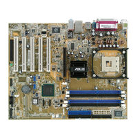
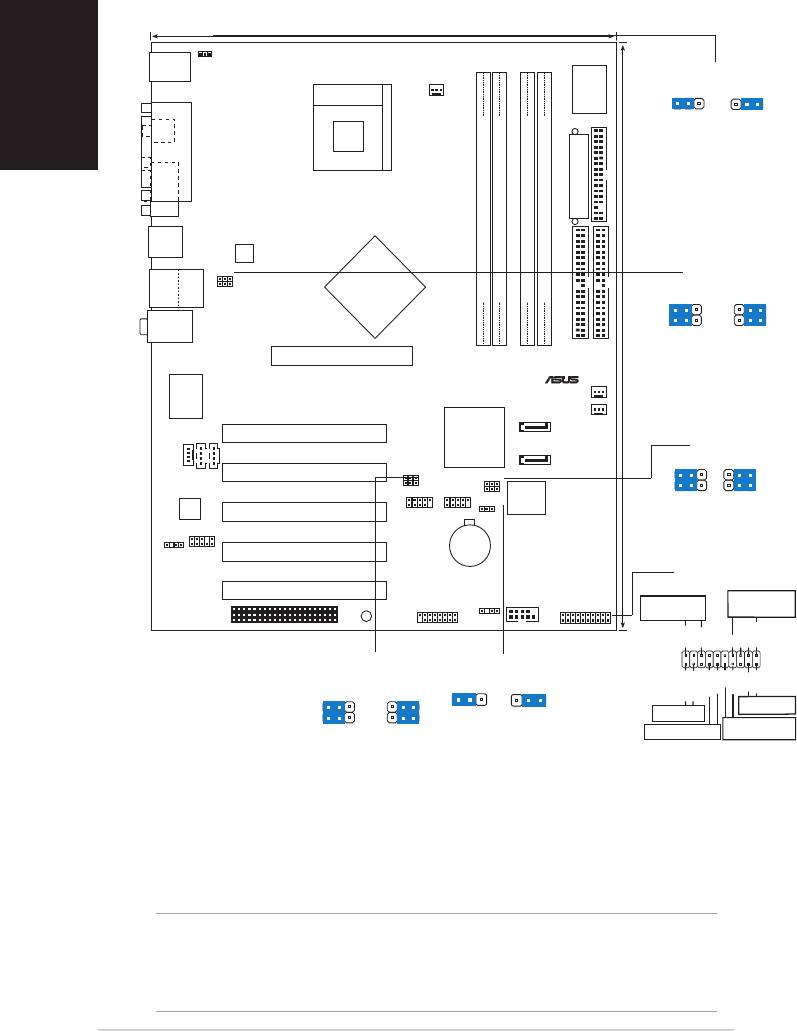
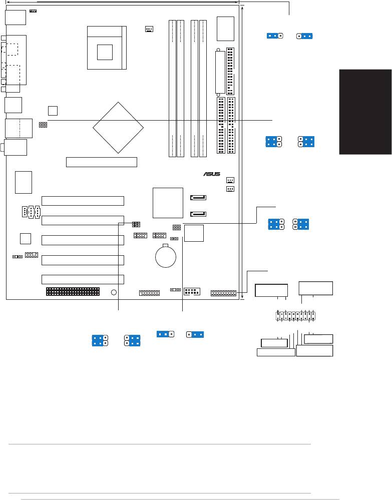
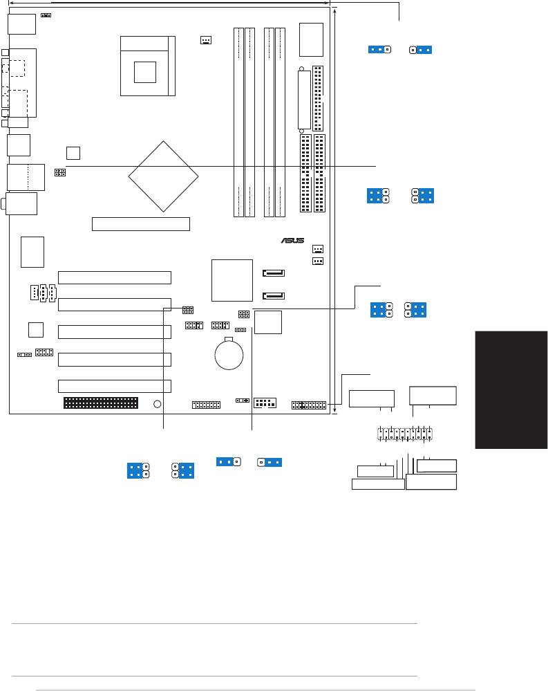
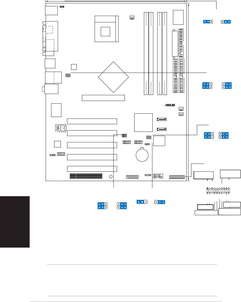
Below:Mic In Accelerated Graphics Port (AGP1) PCI1 AUX1 PCI2 MODEM1 Audio PCI3 Codec P4P800 SE FP_AUDIO PCI4 SPDIF_OUT PCI5 WIFI ASUS P4P800 SE motherboard 24.5cm (9.6in) Socket 478 CPU_FAN1 Intel 82865PE Memory Controller Intel ICH5R USBPW56 SMB20 USBPW78 CLRTC1 USB_56…
-
Page 26: Layout Contents
2.2.4 Layout Contents Slots 1. DDR DIMM slots 2. PCI slots 3. AGP slot 4. Wi-Fi slot Jumpers 1. Clear RTC RAM (3-pin CLRTC) 2. USB device wake-up (3-pin USBPW12, USBPW34, 3. Keyboard power (3-pin KBPWR) 4. SMB 2.0 jumper Rear Panel Connectors 1.
-
Page 27
— System Warning Speaker Lead (Orange 4-pin SPKR) — Reset Switch (Blue 2-pin RESET) — ATX Power Switch (Yellow 2-pin PWRBTN) — System Management Interrupt Lead (Light Blue 2-pin SMI) — Hard Disk Activity LED (Red 2-pin IDE_LED) ASUS P4P800 SE motherboard Page 2-25 2-25 2-25… -
Page 28: Central Processing Unit (Cpu)
Central Processing Unit (CPU) 2.3.1 Overview The motherboard comes with a surface mount 478-pin Zero Insertion Force (ZIF) socket designed for the Intel Take note of the marked corner (with gold triangle) on the CPU. This mark should match a specific corner on the socket to ensure correct installation.
-
Page 29: Installing The Cpu
2. Unlock the socket by pressing the lever sideways, then lift it up to a 90°-100° angle. Make sure that the socket lever is lifted up to 90°-100° angle; otherwise, the CPU does not fit in completely. ASUS P4P800 SE motherboard Socket Lever 90º~100º angle…
-
Page 30
3. Position the CPU above the socket such that its marked corner matches the base of the socket lever. 4. Carefully insert the CPU into the socket until it fits in place. The CPU fits only in one correct orientation. DO NOT force the CPU into the socket to prevent bending the pins and damaging the CPU! 5. -
Page 31: Installing The Heatsink And Fan
Retention Module Base Your boxed Intel installation instructions for the CPU, heatsink, and the retention mechanism. If the instructions in this section do not match the CPU documentation, follow the latter. ASUS P4P800 SE motherboard ® Pentium ® 4 processor, the package ®…
-
Page 32
2. Position the fan with the retention mechanism on top of the heatsink. Align and snap the four hooks of the retention mechanism to the holes on each corner of the module base. Make sure that the fan and retention mechanism assembly perfectly fits the heatsink and module base, otherwise you cannot snap the hooks into the holes. -
Page 33: Connecting The Cpu Fan Cable
CPU fan cable to the connector on the motherboard labeled CPU_FAN. Do not forget to connect the CPU fan connector! Hardware monitoring errors may occur if you fail to plug this connector. ASUS P4P800 SE motherboard CPU Fan Connector (CPU_FAN) 2-11…
-
Page 34: System Memory
Memory Module (DIMM) sockets. The following figure illustrates the location of the sockets. P4P800 SE P4P800 SE 184-Pin DDR DIMM Sockets 2.4.2 Memory configurations You may install 64 MB, 128 MB, 256 MB, 512 MB, and 1GB DDR DIMMs into the DIMM sockets using the memory configurations in this section.
-
Page 35
800 MHz PC3200/PC2700*/PC2100 533 MHz PC2700/PC2100 400 MHz PC2100 *When using 800MHz CPU FSB, PC2700 DDR DIMMs may run only at 320MHz (not 333MHz) due to chipset limitation. ASUS P4P800 SE motherboard Sockets DIMM_A1 DIMM_A2 DIMM_B1 (blue) (black) (blue) Populated —… -
Page 36: Qualified Vendor List
Dual-channel memory configuration . C* — support for 4 modules inserted into the blue & yellow slots as two pairs of Dual-channel memory configuration. Obtain DDR DIMMs only from ASUS qualified vendors. Visit the ASUS website (www.asus.com) for the latest QVL. 2-14 Brand…
-
Page 37: Installing A Dimm
Support the DIMM lightly with your fingers when pressing the retaining clips. The DIMM might get damaged when it flips out with extra force. 2. Remove the DIMM from the socket. ASUS P4P800 SE motherboard DDR DIMM NOTCH Unlocked Retaining Clip…
-
Page 38: Expansion Slots
Expansion slots In the future, you may need to install expansion cards. The motherboard has available PCI slots and an Accelerated Graphics Port (AGP) slot. The following sub-sections describe the slots and the expansion cards that they support. Make sure to unplug the power cord before adding or removing expansion cards.
-
Page 39: Interrupt Assignments
When using PCI cards on shared slots, ensure that the drivers support “Share IRQ” or that the cards do not need IRQ assignments. Otherwise, conflicts will arise between the two PCI groups, making the system unstable and the card inoperable. ASUS P4P800 SE motherboard Standard Function System Timer Keyboard Controller…
-
Page 40: Pci Slots
Install only 1.5V or 0.8V AGP cards on this motherboard! This motherboard does not support 3.3V AGP cards. P4P800 SE P4P800 SE Accelerated Graphics Port (AGP) If installing the ATi 9500 or 9700 Pro Series VGA cards, use only the card version PN xxx-xxxxx-30 or later, for optimum performance and overclocking stability.
-
Page 41: Wi-Fi Slot
2.5.6 Wi-Fi slot The Wi-Fi (Wireless Fidelity) slot supports the ASUS WiFi-b™ module. Visit the ASUS website (www.asus.com) for product updates. The Wi-Fi slot conforms to the Institute of Electrical and Electronics Engineers (IEEE) 802.11b/g standard for wireless devices operating in the 2.4 GHz frequency band.
-
Page 42: Clear Rtc Ram
6. Hold down the <Del> key during the boot process and enter BIOS setup to re-enter data. P4P800 SE P4P800 SE Clear RTC RAM You do not need to clear the RTC when the system hangs due to overclocking. For system failure due to overclocking, use the C.P.R.
-
Page 43: Usb Device Wake-Up
S3 and S4 sleep modes (no power to CPU, DRAM in slow refresh, power supply in reduced power mode). ® P4P800 SE P4P800 SE USB Device Wake Up • The USB device wake-up feature requires a power supply that can provide 500mA on the +5VSB lead for each USB port. Otherwise, the system will not power up.
-
Page 44
1A on the +5VSB lead, and a corresponding setting in the BIOS (see section 4.5.1 Power Up Control). P4P800 SE P4P800 SE Keyboard Power Setting 4. SMB2.0 (two 3-pin SMB20) These jumpers allow you to enable or disable the SMBus 2.0 feature supported on the motherboard. -
Page 45: Connectors
9. Serial connector. This 9-pin COM1 port is for serial devices. 10. S/PDIF Coaxial out jack. This jack connects to external audio output devices with coaxial cable connectors. 11. PS/2 keyboard port. This purple connector is for a PS/2 keyboard. ASUS P4P800 SE motherboard 2-23…
-
Page 46
Rear panel audio ports function variation The functions of the Line Out (lime), Line In (blue), and Mic (pink) ports on the rear panel change when you select the 4-channel or 6-channel audio configuration as shown in the following table. Headphone/ 2-Speaker Light Blue… -
Page 47: Internal Connectors
5 plug). ® P4P800 SE P4P800 SE Floppy Disk Drive Connector 2. IDE connectors (40-1 pin PRI_IDE1, SEC_IDE1) This connector supports the provided UltraDMA100/66 IDE hard disk ribbon cable. Connect the cable’s blue connector to the primary…
-
Page 48
150 MB/s data transfer rate, faster than the standard parallel ATA with 133 MB/s (UltraDMA133). P4P800 SE P4P800 SE SATA Connectors Important notes on Serial ATA • In a legacy operating system (DOS, Windows 98, Windows Me,… -
Page 49
Configuration” for details on the related BIOS items. Windows BIOS item 2000/XP Onboard IDE Operate Mode Enhanced Mode Enhanced Mode Support On S-ATA IDE Port Settings ASUS P4P800 SE motherboard P-ATA Primary Secondary (2 devices) (2 devices) — — Windows 98/Me/NT4.0… -
Page 50
These are not jumpers! DO NOT place jumper caps on the fan connectors! P4P800 SE P4P800 SE 12-Volt Fan Connectors 5. Serial Port 2 connector (10-1 pin COM2) This connector accomodates a second serial port using a serial port bracket. -
Page 51
The minimum recommended wattage is 300W, or 350W for a fully configured system. The system may become unstable or may not boot up if the power is inadequate. ® P4P800 SE P4P800 SE ATX Power Connector ASUS P4P800 SE motherboard ATXPWR1 ATX12V1 +12V DC GND +3.3VDC… -
Page 52: Usb Headers
You must install the driver before you can use the USB 2.0 capability. P4P800 SE P4P800 SE USB 2.0 Header NEVER connect a 1394 cable to any of the USB (blue) connectors. Doing so will damage the motherboard! 2-30 ®…
-
Page 53
® P4P800 SE P4P800 SE Front Panel Audio Connector The Front panel Line-Out connector and the Rear panel Line-Out jack can not work simultaneously. ASUS P4P800 SE motherboard… -
Page 54
By default, the pins labeled “Chassis Signal” and “Ground” are shorted with a jumper cap. If you wish to use the chassis intrusion detection feature, remove the jumper cap from the pins. P4P800 SE P4P800 SE Chassis Alarm Lead 2-32 ® GAME CHASSIS1 ®… -
Page 55: System Panel Connector
This connector accommodates several system front panel functions. ® P4P800 SE P4P800 SE System Panel Connectors • System Power LED Lead (Green 3-1 pin PLED) This 3-1 pin connector connects to the system power LED. The LED lights up when you turn on the system power, and blinks when the system is in sleep mode.
-
Page 56
• Hard disk activity LED (Red 2-pin IDE_LED) This connector supplies power to the hard disk activity LED. Any read or write activity of an IDE device cause this LED to light up. The System Panel connector is color-coded for easy and foolproof connection. -
Page 57: Chapter 3: Powering Up
Chapter 3 This chapter describes the power up sequence, the vocal POST messages and ways of shutting down the system. Powering up…
-
Page 58: Chapter Summary
Chapter summary Starting up for the first time … 3-1 Powering off the computer … 3-2 ASUS P4P800 SE motherboard…
-
Page 59: Starting Up For The First Time
30 seconds from the time you turned on the power, the system may have failed a power-on test. Check the jumper settings and connections or call your retailer for assistance. 7. At power on, hold down <Del> to enter BIOS Setup. Follow the instructions in Chapter 4. ASUS P4P800 SE motherboard…
-
Page 60: Powering Off The Computer
Powering off the computer 3.2.1 Using the OS shut down function If you are using Windows 1. Click the Start button then click Shut Down… 2. Make sure that the Shut down option button is selected, then click the OK button to shut down the computer. 3.
-
Page 61: Chapter 4: Bios Setup
Chapter 4 This chapter tells how to change the system settings through the BIOS Setup menus. Detailed descriptions of the BIOS parameters are also provided. BIOS setup…
-
Page 62
Chapter summary Managing and updating your BIOS … 4-1 BIOS Setup program … 4-9 Main menu … 4-12 Advanced menu … 4-16 Power menu … 4-28 Boot menu … 4-32 Exit menu … 4-37 ASUS P4P800 SE motherboard… -
Page 63: Managing And Updating Your Bios
1. ASUS AFUDOS — Updates the BIOS using a bootable floppy disk in DOS mode. 2. ASUS EZ Flash — Updates the BIOS using a floppy disk during POST. 3. ASUS CrashFree BIOS 2 — Updates the BIOS using a bootable floppy disk or the motherboard support CD.
-
Page 64: Using Afudos To Update The Bios
4.1.2 Using AFUDOS to update the BIOS To update the BIOS using the AFUDOS.EXE utility: 1. Visit the ASUS website (www.asus.com) to download the latest BIOS file for your motherboard. Save the BIOS file to a bootable floppy disk. Write the BIOS file name on a piece of paper. You need to type the exact BIOS file name at the prompt.
-
Page 65: Using Afudos To Copy Bios From Pc
Main filename A:>afudos /oMYBIOS03.rom AMI Firmware Update Utility — Version 1.10 Copyright (C) 2002 American Megatrends, Inc. All rights reserved. Reading flash … 0x0008CC00 (9%) ASUS P4P800 SE motherboard Extension name…
-
Page 66: Using Asus Ez Flash To Update The Bios
4.1.4 Using ASUS EZ Flash to update the BIOS The ASUS EZ Flash feature allows you to easily update the BIOS without having to go through the long process of booting from a diskette and using a DOS-based utility. The EZ Flash is built-in the BIOS firmware so it is accessible by simply pressing <Alt + F2>…
-
Page 67: Recovering The Bios With Crashfree Bios 2
BIOS. See section “4.1.1 Creating a bootable floppy disk.” To recover the BIOS from a floppy disk: 1. Boot the system. 2. When a corrupted BIOS is detected, the following screen message appears. Bad BIOS checksum. Starting BIOS recovery… Checking for floppy… ASUS P4P800 SE motherboard…
-
Page 68
3. Insert a floppy disk that contains the original or the latest BIOS file for this motherboard. If all the necessary files are found in the floppy disk, the BIOS update process continues. Make sure that the BIOS file in the floppy disk is renamed as “P4P800SE.ROM”. -
Page 69: Asus Update
Visit ASUS website (www.asus.com) to download the latest BIOS file. 4.1.6 ASUS Update The ASUS Update is a utility that allows you to update the motherboard BIOS in Windows ® environment. This utility is available in the support CD that comes with the motherboard package.
-
Page 70
3. If you selected updating/ downloading from the Internet, select the ASUS FTP site nearest you to avoid network traffic, or choose Auto Select. Click Next. 4. From the FTP site, select the BIOS version that you wish to download. Click Next. -
Page 71: Bios Setup Program
1. The BIOS setup screens shown in this chapter are for reference purposes only, and may not exactly match what you see on your screen. 2. Visit the ASUS website (www.asus.com) to download the latest product and BIOS information. ASUS P4P800 SE motherboard…
-
Page 72: Bios Menu Screen
4.2.1 BIOS menu screen Menu items Menu bar System Time System Date Legacy Diskette A Legacy Diskette B Primary IDE Master Primary IDE Slave Secondary IDE Master Secondary IDE Slave Third IDE Master Fourth IDE Master IDE Configuration System Information Sub-menu items 4.2.2 Menu bar The menu bar on top of the screen has the following main items:…
-
Page 73: Menu Items
Press Up/Down arrow keys or PageUp/PageDown keys to display the other items on the screen. 4.2.9 General help At the top right corner of the menu screen is a brief description of the selected item. ASUS P4P800 SE motherboard 4-11…
-
Page 74: Main Menu
Main menu When you enter the BIOS Setup program, the Main menu screen appears, giving you an overview of the basic system information. Refer to section “4.2.1 BIOS menu screen” for information on the menu screen items and how to navigate through them. System Time System Date Legacy Diskette A…
-
Page 75: Primary And Secondary Ide Master/Slave; Third And Fourth Ide Master
When set to Disabled, the data transfer from and to the device occurs one sector at a time. Configuration options: [Disabled] [Auto] ASUS P4P800 SE motherboard Select the type of device connected to the system.
-
Page 76: Ide Configuration
PIO Mode [Auto] Selects the PIO mode. Configuration options: [Auto] [0] [1] [2] [3] [4] DMA Mode [Auto] Selects the DMA mode. Configuration options: [Auto] [SWDMA0] [SWDMA1] [SWDMA2] [MWDMA0] [MWDMA1] [MWDMA2] [UDMA0] [UDMA1] [UDMA2] [UDMA3] [UDMA4] [UDMA5] SMART Monitoring [Auto] Sets the Smart Monitoring, Analysis, and Reporting Technology.
-
Page 77
The Serial ATA BOOTROM item appears only when the item Configure S-ATA as RAID is set to [Yes] . IDE Detect Time Out [35] Selects the time out value for detecting ATA/ATAPI devices. Configuration options: [0] [5] [10] [15] [20] [25] [30] [35] ASUS P4P800 SE motherboard 4-15… -
Page 78: System Information
4.3.7 System Information This menu gives you an overview of the general system specifications. The items in this menu are auto-detected by BIOS. AMI BIOS Version : 1001.004 Build Date : 01/27/04 Processor Type : Intel(R) Pentium(R) 4 Family CPU 2.40G Speed : 2400MHz Count…
-
Page 79: Jumperfree Configuration
Allows enhanced system performance. Setting to [Turbo] may cause the system to become unstable. If this happens, revert to the default setting [Auto]. Configuration options: [Auto] [Standard] [Turbo] ASUS P4P800 SE motherboard Select the target CPU frequency, and the [Standard] relevant parameters will be auto-adjusted.
-
Page 80
When you set the AI Overclocking Tuner item to [Manual], the related overclocking items appear. Configure System Frequency/Voltage AI Overclock Tuner CPU External Frequency (MHz) DRAM Frequency AGP/PCI Frequency (MHz) CPU VCore Voltage DDR Reference Voltage AGP VDDQ Voltage Performance Mode CPU External Frequency (MHz) [XXX] Indicates the frequency sent by the clock generator to the system bus and PCI bus. -
Page 81: Cpu Configuration
[Disabled] [Enabled] CPU Internal Thermal Control [Auto] This item allows you to disable or set to auto the CPU Internal Thermal Control function. Configuration options: [Auto] [Disabled] ASUS P4P800 SE motherboard Selects the VID setting at which the processor is to run.
-
Page 82: Chipset
Hyper-Threading Technology [Enabled] This item allows you to enable or disable the processor Hyper-Threading Technology. Configuration options: [Disabled] [Enabled] The Hyper-Threading Technology item appears only when you install an Intel ® Pentium 4.4.3 Chipset The Chipset menu items allow you to change the advanced chipset settings.
-
Page 83
Memory Acceleration Mode [Auto] This field when [Enabled] minimize latencies from CPU to memory to boost system performance. Enable this item to activate the ASUS HyperPath Technology feature. Configuration options: [Auto] [Enabled] Setting to [Enabled] may cause the system to become unstable! If this happens, revert to the default setting [Auto]. -
Page 84: Onboard Devices Configuration
ICH Delayed Transaction [Enabled] Configuration options: [Disabled] [Enabled] MPS Revision [1.1] Configuration options: [1.1] [1.4] 4.4.4 Onboard Devices Configuration OnBoard AC’97 Audio OnBoard LAN OnBoard LAN Boot ROM Serial Port1 Address Serial Port2 Address Parallel Port Address Parallel Port Mode ECP Mode DMA Channel Parallel Port IRQ OnBoard Game/MIDI Port…
-
Page 85
Configuration options: [DMA0] [DMA1] [DMA3] Parallel Port IRQ [IRQ7] Configuration options: [IRQ5] [IRQ7] Onboard Game/MIDI Port [Disabled] Allows you to select the Game Port address or to disable the port. Configuration options: [Disabled] [200/300] [200/330] [208/300] [208/330] ASUS P4P800 SE motherboard 4-23… -
Page 86: Pci Pnp
4.4.5 PCI PnP The PCI PnP menu items allow you to change the advanced settings for PCI/PnP devices. The menu includes setting IRQ and DMA channel resources for either PCI/PnP or legacy ISA devices, and setting the memory size block for legacy ISA devices. Take caution when changing the settings of the PCI PnP menu items.
-
Page 87: Usb Configuration
USB Function [8 USB Ports] Allows you to enable or disable the USB function. Configuration options: [Disabled] [2 USB Ports] [4 USB Ports] [6 USB Ports] [8 USB Ports] ASUS P4P800-E Deluxe motherboard Enables USB host controllers. [8 USB Ports]…
-
Page 88
Legacy USB Support [Auto] Allows you to enable or disable support for legacy USB devices. Setting to Auto allows the system to detect the presence of USB devices at startup. If detected, the USB controller legacy mode is enabled. If no USB device is detected, the legacy USB support is disabled. -
Page 89: Instant Music Configuration
Music CD playback. Configuration options: [IDE Primary Master] [IDE Primary Slave] [IDE Secondary Master] [IDE Secondary Slave] The above item appears only if you enabled the Instant Music item. ASUS P4P800-E Deluxe motherboard If enabled, power up by PS/2 kepyboard…
-
Page 90: Power Menu
Power menu The Power menu items allow you to change the settings for the Advanced Power Management (APM). Select an item then press Enter to display the configuration options. Suspend Mode Repost Video on S3 Resume ACPI 2.0 Support ACPI APIC Support APM Configuration Hardware Monitor 4.5.1 Suspend Mode [Auto]…
-
Page 91: Apm Configuration
[87.5%] [75.0%] [62.5%] [50%] [37.5%] [25%] [12.5%] Power Button Mode [On/Off] Allows the system to go into On/Off mode or suspend mode when the power button is pressed. Configuration options: [On/Off] [Suspend] ASUS P4P800-E Deluxe motherboard Enable or disable APM. [Enabled]…
-
Page 92
Restore on AC Power Loss [Power Off] When set to Power Off, the system goes into off state after an AC power loss. When set to Power On, the system goes on after an AC power loss. When set to Last State, the system goes into either off or on state whatever was the system state before the AC power loss. -
Page 93: Hardware Monitor
Q-Fan Control [Disabled] Allows you to enable or disable the ASUS Q-Fan feature that smartly adjusts the fan speeds for more efficient system operation. When this field is set to [Enabled], the Fan Speed Ratio the appropriate fan speed ratio.
-
Page 94: Boot Menu
CPU Fan Speed [xxxxRPM] or [N/A] Chassis Fan Speed [xxxxRPM] or [N/A] Power Fan Speed [xxxxRPM] or [N/A] The onboard hardware monitor automatically detects and displays the CPU, chassis, and power fan speeds in rotations per minute (RPM). If any of the fans is not connected to the motherboard, the specific field shows N/A.
-
Page 95: Boot Device Priority
This allows you to enable or disable the full screen logo display feature. Configuration options: [Disabled] [Enabled] Make sure that the above item is set to [Enabled] if you wish to use the ASUS MyLogo2™ feature. ASUS P4P800-E Deluxe motherboard Specifies the boot sequence from the [1st Floppy Drive] available devices.
-
Page 96
Add On ROM Display Mode [Force BIOS] Sets the display mode for option ROM. Configuration options: [Force BIOS] [Keep Current] Bootup Num-Lock [On] Allows you to select the power-on state for the NumLock. Configuration options: [Off] [On] PS/2 Mouse Support [Auto] Allows you to enable or disable support for PS/2 mouse. -
Page 97: Security
If you forget your BIOS password, you can clear clear it by erasing the CMOS Real Time Clock (RTC) RAM. See section “2.6 Jumpers” for information on how to erase the RTC RAM. ASUS P4P800-E Deluxe motherboard <Enter> to change password.
-
Page 98: Change User Password
After you have set a supervisor password, the other items appear to allow you to change other security settings. Security Settings Supervisor Password User Password Change Supervisor Password User Access Level Change User Password Clear User Password Password Check Boot Sector Virus Protection User Access Level (Full Access] This item allows you to select the access restriction to the Setup items.
-
Page 99: Exit Menu
Load Setup Defaults Pressing <Esc> does not immediately exit this menu. Select one of the options from this menu or <F10> from the legend bar to exit. ASUS P4P800-E Deluxe motherboard Exit system setup after saving the changes. F10 key can be used for this operation.
-
Page 100
Exit & Save Changes Once you are finished making your selections, choose this option from the Exit menu to ensure the values you selected are saved to the CMOS RAM. The CMOS RAM is sustained by an onboard backup battery and stays on even when the PC is turned off. -
Page 101: Chapter 5: Software Support
Chapter 5 This chapter describes the contents of the support CD that comes with the motherboard package. Software support…
-
Page 102
Support CD information … 5-1 Software Information … 5-7 AI Net feature … 5-12 SoundMAX ® 4 XL software … 5-13 Intel ® RAID for Serial ATA configuration … 5-19 Creating a RAID driver disk … 5-23 ASUS P4P800 SE motherboard… -
Page 103: Install An Operating System
The contents of the support CD are subject to change at any time without notice. Visit the ASUS website for updates. 5.2.1 Running the support CD To begin using the support CD, simply insert the CD into your CD-ROM drive.
-
Page 104: Drivers Menu
5.2.2 Drivers menu The drivers menu shows the available device drivers if the system detects installed devices. Install the necessary drivers to activate the devices. Intel Chipset Inf Update Program This item installs the Intel ® Chipset INF Update Program that enables ®…
-
Page 105: Utilities Menu
This program allows you to download the latest version of the BIOS from the ASUS website. Before using the ASUS Update, make sure that you have an Internet connection so you can connect to the ASUS website. ASUS P4P800 SE motherboard ®…
-
Page 106: Asus Contact Information
Screen display and utilities option may not be the same for other operating system versions. 5.2.4 ASUS Contact Information Clicking the ASUS Contact Information tab displays as stated. You may also find this information in the inside front cover of this user guide. Chapter 5: Software support…
-
Page 107: Other Information
CD. Click an icon to display the specified information. Motherboard Info The window displays the general specifications of the motherboard. Browse this CD The window displays the support CD contents in graphical format. ASUS P4P800 SE motherboard…
-
Page 108
Technical Support Form The window displays the ASUS Technical Support Request Form that you have to fill up when requesting technical support. Filelist The window displays the contents of the support CD and a brief description of each in text format. -
Page 109: Software Information
5.3.1 ASUS MyLogo2™ The ASUS MyLogo2™ is automatically installed when you install the ASUS Update utility from the software menu. See section “5.2.3 Utilities menu”. Before using ASUS MyLogo2™ feature, use the AFUDOS utility to make a copy of your original BIOS file, or obtain the latest BIOS version from the ASUS website.
-
Page 110
Your system boots with the new boot logo. Instead of starting from ASUS Update, you may also launch ASUS MyLogo2 directly from the Windows Start menu to change your BIOS boot logo. After you have modified the BIOS file with the new logo, use the ASUS Update utility to upload the new BIOS. -
Page 111: Asus Instant Music
2. Instant Music does not work if you installed and enabled an add-on sound card. 3. Instant Music only supports PS/2 keyboard. To enable ASUS Instant Music: 1. Connect the analog audio cable from the optical drive (CD-ROM, DVD-ROM, or CD-RW drive) to the 4-pin CD-In connector (labeled CD) on the motherboard.
-
Page 112
To use ASUS Instant Music: 1. Ensure that the power cord is plugged to a grounded power source, so that the system has a standby power. 2. Use either one of the two sets of special function keys on your keyboard to play audio CDs. -
Page 113
7. Refer to the Instant Music function key definitions on the previous page to select other tracks or control the volume. 8. Press <F2> or <Enter> once to stop playing the CD. Press <F2> or <Enter> one more time to eject the CD. ASUS P4P800 SE motherboard 5-11… -
Page 114: Ai Net Feature
AI Net feature The motherboard supports the Marvell Technology. The VCT virtually diagnoses and reports cable faults using the Time Domain Reflectometry (TDR) tool. The VCT technology detects and reports open and shorted cables with up to one meter of accuracy. It also detects impedance mismatches, pair swaps, pair polarity problems, and pair skew problems of up to 64 ns.
-
Page 115: Soundmax ® 4 Xl Software
4 XL software is correctly installed, you will find the SoundMAX the taskbar. From the taskbar, double-click on the SoundMAX4 XL icon to display the SoundMAX ASUS P4P800 SE motherboard ® 4 XL software ® 4 XL with AudioESP™ software to 4 XL requires Microsoft ®…
-
Page 116: Setup Wizards
Setup wizards Use the speaker and microphone setup wizards to fine tune the gain/ attenuation of the inputs/outputs for optimal audio performance. You may launch the setup wizards by clicking the Configuration button when AudioESP detects and verifies a newly connected peripheral, or by clicking on the icon from the SoundMAX control panel.
-
Page 117
The Preferences page of the SoundMAX4 XL allows you to change various audio settings. Listening environment options The SoundMAX4 XL support several audio technologies including SoundMAX SPX™ Animated Audio, 3DPA™, MultiDrive™ 5.1, EnvironmentFC™, MacroFX/ZoomFX™, and Virtual Theater Surround. ASUS P4P800 SE motherboard 5-15… -
Page 118
Rear panel audio ports function variation The functions of the Line Out (lime), Line In (blue), and Mic (pink) ports on the rear panel change when you select the 4-channel or 6-channel audio configuration as shown in the following table. Headphone/ 2-Speaker Light Blue… -
Page 119: Intel Raid For Serial Ata Configuration
1. Attach either cable end to the SATA connector on the motherboard. 2. Attach the other cable end to the SATA hard disk. 3. Connect the SATA power cables. ASUS P4P800 SE motherboard ® RAID 0 and RAID 1 for Serial ATA drives ®…
-
Page 120: Creating, Deleting, And Resetting Raid Sets
5.6.3 Creating, Deleting, and Resetting RAID Sets The Serial ATA RAID set must be configured in the RAID Configuration utility. This configuration can be done by the Intel During the Power-On Self Test (POST), the following message will appear for a few seconds: “Press <Ctrl-I> to enter Raid Configuration Utility”. When this message appears, press <Ctrl+I>…
-
Page 121: Deleting A Raid Volume
Take caution in using this option; All data on the RAID drives will be lost! To delete a RAID volume: 1. Select 2 Delete RAID Volume then press <Enter>. ASUS P4P800 SE motherboard DELETE ARRAY MENU Drives Capacity Status 149.0GB Normal HELP [<ESC>]-Previous Menu…
-
Page 122: Reset Raid Data
2. Press <Del> to delete the RAID volume. Are you sure you want to delete this volume? Are you sure you want to delete volume «RAID_Volume1»? (Y/N) 3. The utility prompts a verification message, press <Y>. 5.6.6 Reset RAID Data Copyright(C) 2003 Intel Corporation.
-
Page 123: Creating A Raid Driver Disk
SCSI or RAID driver. 2. Press <F6> then insert the RAID disk driver into the floppy disk drive. 3. Follow the succeeding screen instructions to complete the installation. ASUS P4P800 SE motherboard ® RAID driver is required when installing ®…
-
Page 124
5-22 Chapter 5: Software support…
- Manuals
- Brands
- Asus Manuals
- Motherboard
- P4P800 SE
Manuals and User Guides for Asus P4P800 SE. We have 2 Asus P4P800 SE manuals available for free PDF download: User Manual, Guía De Inicio Rápido
Asus P4P800 SE User Manual (125 pages)
Asus Computer Hardware — Motherboard User Manual
Brand: Asus
|
Category: Motherboard
|
Size: 5.51 MB
Table of Contents
-
Table of Contents
3
-
Notices
7
-
Federal Communications Commission Statement
7
-
Canadian Department of Communications Statement
7
-
-
Safety Information
8
-
Electrical Safety
8
-
About this Guide
9
-
How this Guide Is Organized
9
-
Where to Find more Information
9
-
Conventions Used in this Guide
10
-
Typography
10
-
-
P4P800 SE Specifications Summary
11
-
Chapter 1: Product Introduction
13
-
Welcome
15
-
Package Contents
15
-
Special Features
16
-
Product Highlights
16
-
Unique ASUS Features
18
-
Asus Mylogo2
19
-
-
-
Chapter 2: Hardware Information
21
-
Before You Proceed
23
-
Motherboard Overview
24
-
Placement Direction
24
-
Screw Holes
24
-
Motherboard Layout
25
-
Layout Contents
26
-
-
Central Processing Unit (CPU)
28
-
Overview
28
-
Installing the CPU
29
-
Installing the Heatsink and Fan
31
-
Connecting the CPU Fan Cable
33
-
-
System Memory
34
-
Overview
34
-
Memory Configurations
34
-
Qualified Vendor List
36
-
Installing a DIMM
37
-
Removing a DIMM
37
-
-
Expansion Slots
38
-
Installing an Expansion Card
38
-
Configuring an Expansion Card
38
-
Interrupt Assignments
39
-
PCI Slots
40
-
AGP Slot
40
-
Wi-Fi Slot
41
-
Clear Rtc Ram
42
-
-
Jumpers
42
-
USB Device Wake-Up
43
-
Connectors
45
-
Rear Panel Connectors
45
-
Internal Connectors
47
-
Usb Headers
52
-
System Panel Connector
55
-
-
-
-
Chapter 3: Powering up
57
-
Chapter Summary
58
-
Starting up for the First Time
59
-
Powering off the Computer
60
-
Using the os Shut down Function
60
-
Using the Dual Function Power Switch
60
-
-
-
Chapter 4: BIOS Setup
61
-
Managing and Updating Your BIOS
63
-
Creating a Bootable Floppy Disk
63
-
Using AFUDOS to Update the BIOS
64
-
Using AFUDOS to Copy BIOS from PC
65
-
Using ASUS EZ Flash to Update the BIOS
66
-
Recovering the BIOS with Crashfree BIOS 2
67
-
ASUS Update
69
-
-
BIOS Setup Program
71
-
BIOS Menu Screen
72
-
Menu Bar
72
-
Navigation Keys
72
-
Menu Items
73
-
Sub-Menu Items
73
-
Configuration Fields
73
-
Pop-Up Window
73
-
Scroll Bar
73
-
General Help
73
-
-
Main Menu
74
-
System Time
74
-
System Date
74
-
Legacy Diskette a
74
-
Language
74
-
Primary and Secondary IDE Master/Slave; Third and Fourth IDE Master
75
-
IDE Configuration
76
-
System Information
78
-
-
Advanced Menu
78
-
Jumperfree Configuration
79
-
CPU Configuration
81
-
Chipset
82
-
Onboard Devices Configuration
84
-
PCI Pnp
86
-
USB Configuration
87
-
Instant Music Configuration
89
-
-
Power Menu
90
-
Suspend Mode
90
-
Repost Video on S3 Resume
90
-
ACPI 2.0 Support
90
-
ACPI APIC Support
90
-
APM Configuration
91
-
Hardware Monitor
93
-
-
Boot Menu
94
-
Boot Device Priority
95
-
Boot Settings Configuration
95
-
Security
97
-
Change User Password
98
-
-
Exit Menu
99
-
-
Chapter 5: Software Support
101
-
Install an Operating System
103
-
Support CD Information
103
-
Running the Support CD
103
-
Drivers Menu
104
-
Utilities Menu
105
-
ASUS Contact Information
106
-
Other Information
107
-
-
Software Information
109
-
ASUS Mylogo2
109
-
ASUS Instant Music
111
-
-
AI Net Feature
114
-
Soundmax ® 4 XL Software
115
-
Setup Wizards
116
-
-
Intel RAID for Serial ATA Configuration
119
-
Intel ® RAID for Serial ATA Configuration
119
-
BIOS Configuration
119
-
Installing Serial ATA (SATA) Hard Disks
119
-
Installing Serial ATA Hard Disks
119
-
Creating, Deleting, and Resetting RAID Sets
120
-
Creating a RAID Volume
120
-
Deleting a RAID Volume
121
-
Reset RAID Data
122
-
-
Creating a RAID Driver Disk
123
-
Advertisement

(French) Asus P4P800 SE Guía De Inicio Rápido (16 pages)
Motherboard DIY Troubleshooting Guide
Brand: Asus
|
Category: Motherboard
|
Size: 0.24 MB
Table of Contents
-
Quick Start Guide
1
-
Installation du Processeur
2
-
Mémoire Système
3
-
Motherboard Layout
5
-
Installieren der Cpu
5
-
Instalación de la CPU
11
Advertisement
Related Products
-
Asus P4P800-X
-
Asus P4P800S-X
-
Asus P4P800-E DELUXE
-
Asus P4P800-MX
-
Asus p4p800s
-
Asus P4P800-VM
-
ASUS P4P800 DELUXE
-
Asus P4P800S-E Deluxe
-
Asus P4P800-F
-
Asus P4P8X SE
Asus Categories
Motherboard
![]()
Laptop
![]()
Desktop
![]()
Monitor
![]()
Network Router
More Asus Manuals
Раздел: Компьютерная техника, комплектующие, аксессуары
Тип: Материнская Плата
Инструкция к Материнской Плате Asus P4P800 SE

U1535
P4P800 SE
Quick Start Guide
Français
Deutsch
Italiano
Español
усский
First Edition V1 Published January 2004
Copyright © 2004 ASUSTeK COMPUTER INC. All Rights Reserved.
15-063405100
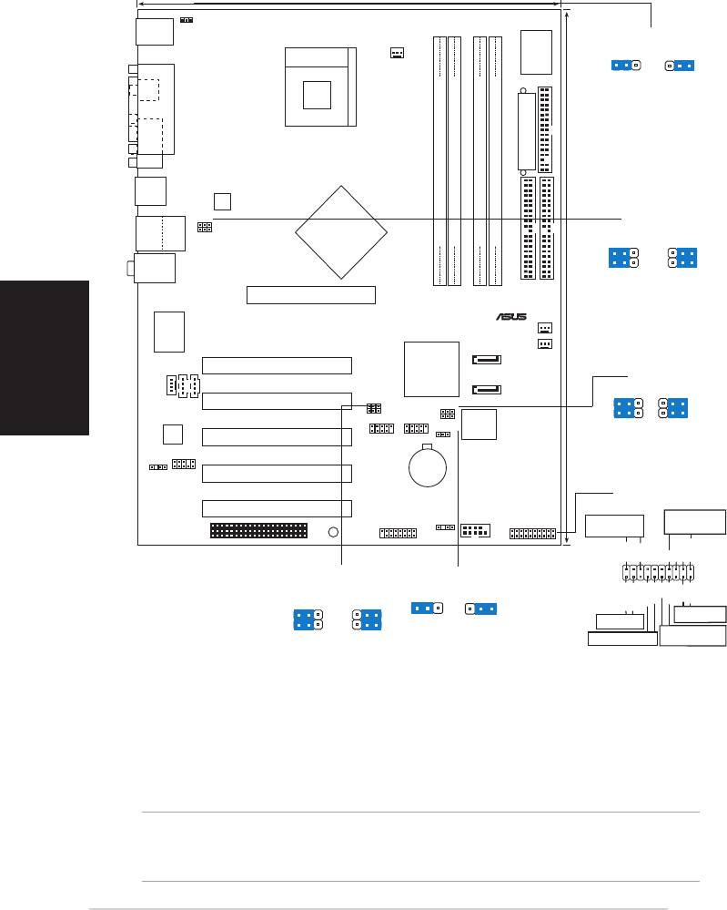
1. Schéma de la Carte Mère
24.5cm (9.6in)
Français
PS/2KBMS
KBPWR
T: Mouse
B: Keyboard
KBPWR
Socket 478
2312
CPU_FAN1
I/O
Super
+5V +5VSB
SPDIF_O
(Default)
PARALLEL PORT
COM1
ATX Power Connector
FLOPPY1
USB20_12
ATX12V1
Intel
USBPW12
82865PE
USB2.0
Top:
USBPW34
T: USB3
RJ-45
USBPW12
Memory
DDR DIMM_A1 (64 bit,184-pin module)
DDR DIMM_A2 (64 bit,184-pin module)
DDR DIMM_B1 (64 bit,184-pin module)
DDR DIMM_B2 (64 bit,184-pin module)
B: USB4
USBPW34
Controller
21
2
3
Top:Line In
Hub
Center:Line Out
Below:Mic In
+5V
+5VSB
(Default)
Accelerated Graphics Port (AGP1)
PRI_IDE1
®
SEC_IDE1
30.5cm (12.0in)
CHA_FAN1
Marvell
88E8001
Gbit LAN
PWR_FAN1
SATA1
PCI1
Intel
CD1
ICH5R
AUX1
SATA2
SMB20
21
2
3
MODEM1
PCI2
USBPW56
SMB20
USBPW78
4Mbit
Audio
CLRTC1
Firmware
Enable
Disable
Hub
(Default)
Codec
PCI3
USB_56 USB_78
FP_AUDIO
P4P800 SE
CR2032 3V
Lithium Cell
SPDIF_OUT
PCI4
CMOS Power
PANEL1
PCI5
SB_PWR1
GAME1
CHASSIS1
COM2
Connecteur
PANEL1
LED alimentation
Haut-parleur
WIFI
PLED+
PLED-
+5V
Ground
Ground
Speaker
USBPW56
CLRTC1
USBPW78
12 23
PWR
Reset
21
2
3
ExtSMI#
Ground
Ground
Ground
IDE_LED+
IDE_LED-
Bouton de reset
Normal Clear CMOS
IDE_LED
(Default)
Commutateur
+5V
+5VSB
SMI Lead
d’alimentation ATX*
(Default)
* Nécessite une alimentation ATX.
2. Installation du Processeur
Suivez les étapes ci-dessous pour installer le processeur.
1. Repérez le support ZIF de 478-broches situé sur la carte mère.
2. Soulevez le levier du support à un angle de 90° minimum.
AVERTISSEMENT !
Le processeur s’insère uniquement dans le bon sens. NE PAS forcer le
processeur sur son support pour éviter de tordre les broches et d’endommager
ainsi le processeur!
2
Carte mère ASUS P4P800 SE

3. Positionnez le processeur au-dessus du support de manière à ce que son bord
marqué corresponde à la base du levier du support.
4. Insérez avec soin le processeur sur son support jusqu’à ce qu’il s’insère
correctement.
5. Une fois le processeur mis en place, rabattez le levier du support pour sécuriser
le processeur. Le levier se bloque sur le petit ergot latéral pour indiquer qu’il est
en place.
Français
3. Mémoire Système
La carte mère dispose de quatre emplacements DIMM DDR (Double Data Rate)
supportant les DIMM non-ECC PC3200/2700/2100 pour un total pouvant atteindre
4GB de mémoire système.
REMARQUES
1. Lisez les remarques importantes relatives à la configuration de la
mémoire décrites dans le guide utilisateur avant d’installer les DIMM.
2. Assurez-vous de bien couper l’alimentation avant d’ajouter ou de retirer
les DIMM pour éviter d’endommager les DIMM ou d’autres composants
du système.
Tableau 1 Configurations Mémoire Recommandées
Emplacements
Mode DIMM_A1 DIMM_A2 DIMM_B1 DIMM_B2
(bleu) (noir) (bleu) (noir)
Simple canal (1) Occupé — — —
(2) — Occupé — —
(3) — — Occupé —
(4) — — — Occupé
Double canal (1) Occupé
— Occupé —
(2) — Occupé — Occupé
(3)* Occupé Occupé Occupé Occupé
* Pour réaliser une configuration à double-canal (3), vous pouvez :
• installer des DIMM identiques dans les quatre emplacements, ou
• installer une paire de DIMM identiques dans les emplacements DIMM_A1 et
DIMM_B1 (emplacements bleus) et une autre paire de DIMM identiques dans
les emplacements DIMM_A2 et DIMM_B2 (emplacements noirs)
Tableau 2 Synchronisation entre la Fréquence Mémoire et la
FSB du processeur
FSB du CPU Type DIMM DDR Fréquence Mémoire
800 MHz PC3200/PC2700*/PC2100 400/333*/266 MHz
533 MHz PC2700/PC2100 333/266 MHz
400 MHz PC2100 266 MHz
* Lorsque vous utilisez une FSB de processeur à 800MHz, les DIMM DDR PC2700
peuvent fonctionner uniquement à 320MHz (au lieu de 333MHz) en raison des
limitations du chipset.
Carte mère ASUS P4P800 SE
3

4. Informations du BIOS
La ROM Flash sur la carte mère contient un BIOS. Vous pouvez mettre à jour les
Français
informations du BIOS ou configurer ses paramètres en utilisant l’utilitaire de Setup
du BIOS. Les écrans BIOS comprennent les clés de navigation et une courte aide en
ligne pour vous guider. Si vous rencontrez des problèmes liés au système ou si le
système devient instable une fois que vous aurez modifié les paramètres, chargez
les Paramètres de Réglage Par Défaut. Référez-vous au Chapitre 4 du guide
utilisateur pour obtenir plus d’informations détaillées relatives au BIOS. Rendez visite
au site web d’ASUS (www.asus.com) pour obtenir les mises à jour.
Pour accéder au Setup lors du démarrage:
Pressez <Suppr> lors du Test Automatique de Démarrage (POST : Power-On Self
Test ). Si vous ne pressez pas la touche <Suppr>, le POST continuera son programme
de test.
Pour accéder au Setup après le POST:
• Redémarrez le système en pressant <Ctrl> + <Alt> + <Suppr>, puis pressez
<Suppr> lors du POST, ou
• Pressez le bouton de réinitialisation situé sur le châssis puis pressez
<Suppr> lors du POST, ou
• Eteignez et rallumez le système puis pressez <Suppr> lors du POST.
Pour mettre à jour le BIOS avec AFUDOS:
Bootez le système à l’aide d’une disquette qui contient le dernier fichier BIOS. A
l’ouverture de la session DOS, saisissez afudos /i<filename.rom> puis pressez
Entrée. Rebootez le système lorsque la mise à jour sera terminée.
Pour mettre à jour le BIOS avec ASUS EZ Flash:
Bootez le système puis pressez <Alt>-<F2> lors du POST pour lancer EZ Flash.
Insérez la disquette qui contient le dernier fichier BIOS. EZ Flash effectuera le
processus de mise à jour du BIOS et rebootera automatiquement le système une
fois qu’il aura terminé.
Pour récupérer le BIOS avec CrashFree BIOS 2:
Bootez le système. Si le BIOS est corrompu, l’outil de récupération automatique CrashFree
BIOS 2 détectera une disquette ou un CD pour restaurer le BIOS. Insérez le CD de
support pour la carte mère ou une disquette qui contient le fichier BIOS original ou le
dernier fichier BIOS. Rebootez le système une fois que le BIOS sera rétabli.
5. Informations sur le CD technique
Cette carte mère supporte les systèmes d’exploitation Windows 98SE/ME/2000/XP.
Installez toujours la dernière version d’OS et les mises à jour correspondantes de
manière à maximiser les caractéristiques de votre hardware.
Le CD technique livré avec la carte mère contient des logiciels et de nombreux pilotes
et utilitaires qui améliorent les fonctions de la carte mère. Pour utiliser le CD technique,
insérez-le simplement dans votre lecteur CD-ROM. si Autorun est activé dans votre
ordinateur, le CD affiche automatiquement l’écran de bienvenue et les menus
d’installation. Si l’écran de bienvenue n’apparaît pas automatiquement, localisez le
fichier ASSETUP.EXE dans le dossier BIN du CD technique et double-cliquez dessus.
4
Carte mère ASUS P4P800 SE
1. Motherboard layout
24.5cm (9.6in)
PS/2KBMS
KBPWR
T: Mouse
B: Keyboard
KBPWR
Socket 478
CPU_FAN1
I/O
2312
Super
+5V +5VSB
SPDIF_O
(Default)
PARALLEL PORT
COM1
ATX Power Connector
FLOPPY1
USB20_12
ATX12V1
Intel
USBPW12
82865PE
USB2.0
Top:
USBPW34
T: USB3
RJ-45
USBPW12
Memory
DDR DIMM_A1 (64 bit,184-pin module)
DDR DIMM_A2 (64 bit,184-pin module)
DDR DIMM_B1 (64 bit,184-pin module)
DDR DIMM_B2 (64 bit,184-pin module)
B: USB4
USBPW34
Controller
21
2
3
Deutsch
Top:Line In
Hub
Center:Line Out
Below:Mic In
+5V
+5VSB
(Default)
Accelerated Graphics Port (AGP1)
PRI_IDE1
®
SEC_IDE1
30.5cm (12.0in)
CHA_FAN1
Marvell
88E8001
Gbit LAN
PWR_FAN1
SATA1
CD1
PCI1
Intel
ICH5R
SATA2
SMB20
AUX1
21
2
3
MODEM1
PCI2
USBPW56
SMB20
USBPW78
4Mbit
Audio
CLRTC1
Firmware
Enable
Disable
Hub
(Default)
Codec
PCI3
USB_56 USB_78
FP_AUDIO
P4P800 SE
CR2032 3V
Lithium Cell
SPDIF_OUT
PCI4
CMOS Power
PANEL1
PCI5
SB_PWR1
GAME1
CHASSIS1
COM2
PANEL1
Lautsprecher-
Strom-LED
WIFI
anschluss
PLED+
PLED-
+5V
Ground
Ground
Speaker
USBPW56
CLRTC1
USBPW78
12 23
PWR
21
2
3
Ground
Ground
Reset
Ground
IDE_LED+
IDE_LED-
ExtSMI#
Normal Clear CMOS
Reset-Schalter
IDE-LED
(Default)
+5V
+5VSB
SMI-Leiter
ATX-Stromschalter*
(Default)
* Benötigt ATX-Stromversorgung.
2. Installieren der CPU
Folgen Sie bitte den nachstehenden Schritten, um eine CPU zu installieren.
1. Suchen Sie auf dem Motherboard den 478-pol. ZIF-Sockel.
2. Heben Sie den Sockelhebel bis zu einem Winkel von 90 Grad hoch.
WARNUNG!
Die CPU passt nur in einer Richtung in den Sockel. Stecken Sie die CPU nicht
gewaltsam hinein, um verbogene Kontaktstifte und Schäden an der CPU zu
vermeiden!
ASUS P4P800 SE-Motherboard
5

3. Richten Sie die markierte Ecke der CPU auf die Sockelecke, die dem
Hebelscharnier am nächsten liegt, aus.
4. Setzen Sie die CPU vorsichtig in den Sockel ein. Achten Sie auf den korrekten Sitz.
5. Sobald die CPU richtig sitzt, drücken Sie den Sockelhebel nach unten, um die
CPU zu arretieren. Sie hören einen Klickton, wenn der Hebel einrastet.
3. Arbeitsspeicher
Das Motherboard ist mit vier Double Data Rate (DDR)-DIMM-Steckplätzen
ausgestattet. Diese Steckplätze unterstützen bis zu 4 GB Systemspeicher aus Nicht-
ECC PC3200/2700/2100 DIMMs.
Deutsch
HINWEISE
1. Lesen Sie bitte vor der DIMM-Installation die wichtigen Hinweise zu
Speicherkonfigurationen im Benutzerhandbuch.
2. Vor dem Ein- oder Ausbau von DIMM-Modulen bitte unbedingt den
Netzstecker ziehen, um Schäden an den Modulen oder anderen
Systemkomponenten zu vermeiden.
Tabelle 1 Empfohlene Arbeitsspeicherkonfigurationen
Steckplätze
Modus DIMM_A1 DIMM_A2 DIMM_B1 DIMM_B2
(blau) (schwarz) (blau) (schwarz)
Ein-Kanal (1) Installiert — — —
(2) — Installiert — —
(3) — — Installiert —
(4) — — — Installiert
Dual-Kanal (1) Installiert
— Installiert —
(2) — Installiert — Installiert
(3)* Installiert Installiert Installiert Installiert
* Bei einer Dual-Kanalkonfiguration (3) können Sie:
• identische DIMMs in alle vier Steckplätze einstecken, oder
• ein identisches DIMM-Paar in DIMM_A1 und DIMM_B1 (blaue Steckplätze) und
ein identisches DIMM-Paar in DIMM_A2 und DIMM_B2 (schwarze Steckplätze)
einstecken.
Tabelle 2 Speicherfrequenz-/CPU FSB-Synchronisation
CPU FSB DDR DIMM-Typ Speicherfrequenz
800 MHz PC3200/PC2700*/PC2100 400/333*/266 MHz
533 MHz PC2700/PC2100 333/266 MHz
400 MHz PC2100 266 MHz
* Wenn Sie eine CPU FSB von 800MHz verwenden, dann können PC2700 DDR DIMMs
wegen der Chipsatzeinschränkung nur mit 320MHz (nicht 333MHz) arbeiten.
6
ASUS P4P800 SE-Motherboard

4. BIOS-Informationen
Das BIOS ist in einem Flash-ROM auf dem Motherboard gespeichert. Sie können
mit Hilfe des BIOS-Setupprogramms die BIOS-Informationen aktualisieren oder die
Parameter konfigurieren. Auf den BIOS-Seiten finden Sie Navigationstasten und eine
kurze Online-Hilfe. Laden Sie bitte die Standardwerte (Setup-Defaults), wenn
Systemprobleme auftreten oder das System unstabil geworden ist, nachdem die
Einstellungen geändert wurden. Sehen Sie im Kapitel 4 des Benutzerhandbuchs für
ausführende BIOS-Informationen nach. Besuchen Sie die ASUS-Website
(www.asuscom.de/bios) für die jeweils aktuellste BIOS-Version.
Aufrufen des Setupprogramms beim Starten:
Drücken Sie die Taste <Entf> während des Einschaltselbsttests (POST); ansonsten
setzt der POST seine Testroutinen fort.
Aufrufen des Setupprogramms nach dem POST:
• Starten Sie das System erneut, indem Sie <Strg> + <Alt> + <Entf> drücken.
Deutsch
Drücken Sie anschließend <Entf> während des POST.
• Oder drücken Sie die Reset-Taste am Computergehäuse. Drücken Sie
anschließend <Entf> während des POST.
• Oder schalten Sie das System aus und dann wieder ein. Drücken Sie anschließend
<Entf> während des POST.
Aktualisieren des BIOS mit AFUDOS:
Booten Sie das System von einer Diskette, die die neueste BIOS-Datei enthält. Tippen
Sie in die DOS-Eingabeaufforderung afudos /i<filename.rom> ein und drücken
anschließend die Eingabetaste. Starten Sie das System neu, nachdem die
Aktualisierung vervollständigt wurde.
Aktualisieren des BIOS mit ASUS EZ Flash:
Booten Sie das System neu und drücken <Alt>-<F2> während des POST, um EZ
Flash zu starten. Legen Sie die Diskette, die die neueste BIOS-Datei enthält, ein. EZ
Flash führt den BIOS-Aktualisierungsprozess aus und startet das System automatisch
nach dem Vervollständigen des Prozesses neu.
Wiederherstellen des BIOS mit CrashFree BIOS 2:
Booten Sie das System. Wenn das BIOS beschädigt ist, sucht das CrashFree BIOS
2 Auto-Wiederherstellungsdienstprogramm eine Diskette oder CD, mit der das BIOS
wiederhergestellt werden kann. Legen Sie die Motherboard Support-CD oder eine
Diskette, die die originale oder neueste BIOS-Datei enthält, ein. Starten Sie das System
neu, nachdem das BIOS wiederhergestellt wurde.
5. Informationen über die Software Support CD
Das Motherboard unterstützt die Windows 98SE/ME/2000/XP-Betriebssysteme.
Verwenden Sie bitte immer die jeweils letzte Version des Betriebssystems und führen
ggf. die notwendigen Aktualisierungen durch, um die maximale Leistung Ihrer
Hardware zu erhalten.
Die dem Motherboard beigefügte Support CD beinhaltet nützliche Software und einige
Utility-Treiber, die die Funktionen des Motherboards verstärken. Legen Sie einfach
die CD in Ihr CD-ROM-Laufwerk ein. Ein Begrüßungsbild, sowie ein Installationsmenü,
erscheinen automatisch, wenn die Autorun-Funktion in Ihrem System aktiviert ist.
Falls das Begrüßungsfenster nicht automatisch erscheint, klicken Sie bitte doppelt
auf die Datei ASSETUP.EXE in dem BIN-Ordner auf der Support CD, um das
Installationsmenü aufzurufen.
ASUS P4P800 SE-Motherboard
7
1. Diagramma disposizione scheda madre
24.5cm (9.6in)
PS/2KBMS
KBPWR
T: Mouse
B: Keyboard
KBPWR
Socket 478
I/O
2312
CPU_FAN1
Super
+5V +5VSB
SPDIF_O
(Default)
PARALLEL PORT
COM1
ATX Power Connector
FLOPPY1
USB20_12
ATX12V1
Intel
USBPW12
82865PE
USB2.0
Top:
USBPW34
T: USB3
RJ-45
USBPW12
Memory
DDR DIMM_A1 (64 bit,184-pin module)
DDR DIMM_A2 (64 bit,184-pin module)
DDR DIMM_B1 (64 bit,184-pin module)
DDR DIMM_B2 (64 bit,184-pin module)
B: USB4
USBPW34
Controller
21
2
3
Top:Line In
Hub
Center:Line Out
Below:Mic In
+5V
+5VSB
(Default)
Accelerated Graphics Port (AGP1)
PRI_IDE1
®
SEC_IDE1
30.5cm (12.0in)
Italiano
CHA_FAN1
Marvell
88E8001
Gbit LAN
PWR_FAN1
SATA1
PCI1
Intel
CD1
ICH5R
SATA2
SMB20
AUX1
21
2
3
MODEM1
PCI2
USBPW56
SMB20
USBPW78
4Mbit
CLRTC1
Firmware
Enable
Disable
Audio
Hub
(Default)
Codec
PCI3
USB_56 USB_78
FP_AUDIO
P4P800 SE
CR2032 3V
Lithium Cell
SPDIF_OUT
PCI4
CMOS Power
PANEL1
PCI5
SB_PWR1
CHASSIS1
LED della
Connettore
GAME1
COM2
PANEL1
WIFI
corrente
altoparlanti
PLED+
PLED-
+5V
Ground
Ground
Speaker
USBPW56
CLRTC1
USBPW78
12 23
PWR
Reset
21
2
3
ExtSMI#
Ground
Ground
Ground
IDE_LED+
IDE_LED-
Interruttore
Normal Clear CMOS
IDE_LED
Reimposta
(Default)
+5V
+5VSB
Interruttore di
SMI Lead
(Default)
corrente ATX*
* Richiede una fonte di alimentazione ATX.
2. Installazione della CPU
Attenersi alle fasi seguenti per installare una CPU.
1. Ubicare la presa ZIF a 478 pin sulla scheda madre.
2. Sollevare la leva della presa ad un angolo di almeno 90°.
AVVISO!
La CPU può essere inserita solamente con un corretto orientamento. NON forzare
la CPU nella presa diversamente si possono piegare i pin e danneggiare la CPU!
8
Scheda madre ASUS P4P800 SE

3. Porre la CPU sulla presa in modo che gli angoli contrassegnati coincidano con la
base della leva della presa.
4. Inserire completamente con delicatezza la CPU nella presa.
5. Quando la CPU è al suo posto, abbassare la leva della presa per bloccare la
CPU. La leva scatta sulla linguetta laterale indicando che è bloccata.
3. Memoria di sistema
La scheda madre ha quattro prese DIMM DDR (Double Data Rate) che supportano
DIMM non-ECC PC3200/2700 / 2100 per memorie di sistema con dimensioni massime
di 4 GB.
NOTE
1. Prima di installare i DIMM leggere le note riguardo alla configurazione
della memoria riportate nella Guida utente.
2. Assicurarsi di scollegare l’alimentazione prima di aggiungere o rimuovere
i DIMM per evitare di danneggiare questi ultimi o qualsiasi altro componente
del sistema.
Tavola1 Configurazioni raccomandate della memoria
Prese
Modalità DIMM_A1 DIMM_A2 DIMM_B1 DIMM_B2
Italiano
(Blu) (Nero) (Blu) (Nero)
Canale singolo (1) Corredato — — —
(2) — Corredato — —
(3) — — Corredato —
(4) — — — Corredato
Canale doppio (1) Corredato
— Corredato —
(2) — Corredato — Corredato
(3)* Corredato Corredato Corredato Corredato
* Per la configurazione canale doppio (3), si può:
• installare DIMM identici su tutte le quattro prese, oppure
• installare coppie identiche di DIMM su DIMM_A1 e DIMM_B1 (prese blu) e coppie
identiche di DIMM su DIMM_A2 e DIMM_B2 (prese nere)
Tavola 2 Frequenza della memoria / sincronizzazione FSB CPU
CPU FSB Tipo DIMM DDR Frequenza memoria
800 MHz PC3200/PC2700*/PC2100 400/333*/266 MHz
533 MHz PC2700/PC2100 333/266 MHz
400 MHz PC2100 266 MHz
* Quando si utilizza FSB CPU 800 MHz, i DIMM DDR PC2700 possono funzionare
solamente a 320 MHz (non a 333 MHz) a causa delle limitazioni del Chipset.
Scheda madre ASUS P4P800 SE
9

4. Informazioni sul BIOS
La Flash ROM sulla scheda madre contiene il BIOS. È possibile aggiornare le
informazioni del BIOS, o configurare i parametri utilizzando l’utilità di configurazione
BIOS Setup. La schermata BIOS include tasti di navigazione ed una concisa guida in
linea. Se si riscontrano problemi con il sistema, oppure se questo diventa instabile
dopo avere modificato le impostazioni, caricare le impostazioni predefinite di
configurazione Setup Defaults. Fare riferimento al Capitolo 4 della Guida utente per
informazioni dettagliate sul BIOS. Visitare la pagina Web ASUS (www.asus.com)
per gli aggiornamenti.
Per accedere al Setup all’avvio:
Premere il tasto <Delete> durante il POST (Power On Self Test). Se non si preme il
tasto <Delete>, il POST continua le sue routine di diagnostica.
Per accedere al Setup dopo il POST:
• Riavviare il sistema premendo i tasti <Ctrl> + <Alt> + <Delete>, poi premere il
tasto <Delete> durante il POST, oppure
• Premere il tasto di ripristino sul telaio, poi premere il tasto <Delete> durante il
POST, oppure
Italiano
• Spegnere e riaccendere il sistema e poi premere il tasto <Delete> durante il POST
Per aggiornare il BIOS con AFUDOS:
Avviare il sistema da un dischetto floppy che contenga il file BIOS più aggiornato. Al
prompt di DOS, scrivere: afudos /i<filename.rom> poi premere il tasto Enter / Invio.
Riavviare il sistema quando l’aggiornamento è completato.
Per aggiornare il BIOS con ASUS EZ Flash:
Avviare il sistema e premere <Alt>-<F2> durante il POST per avviare EZ Flash.
Inserire un dischetto floppy che contenga il file BIOS più aggiornato. EZ Flash esegue
le procedure d’aggiornamento del BIOS e, una volta completato, riavvia
automaticamente il sistema.
Per ripristinare il BIOS con CrashFree BIOS 2:
Avviare il sistema. Se il BIOS è corrotto lo strumento di ripristino automatico di
CrashFree BIOS 2 cerca un dischetto floppy o un CD per ripristinare il BIOS. Inserire
il CD di supporto della scheda madre, oppure un dischetto floppy che contenga il file
BIOS originale o più aggiornato. Riavviare il sistema quando il BIOS è ripristinato.
5. Informazioni sul CD di supporto al Software
Questa scheda madre supporta un sistema operativo (OS) Windows 98SE/ME/2000/
XP. Installate sempre l’ultima versione OS e gli aggiornamenti corrispondenti, in modo
da massimizzare le funzioni del vostro hardware.
Il CD di supporto in dotazione alla scheda madre contiene dei software utili e diversi
utility driver che potenziano le funzioni della scheda madre. Per cominciare a usare il
CD di supporto, basta inserire il CD nel CD-ROM drive. Il CDmostra automaticamente
lo schermo di benvenuto e i menu dell’installazione se Autorun è attivato nel vostro
computer. Se lo schermo di benvenuto non compare automaticamente, trovate e
cliccate due volte il file ASSETUP.EXE dalla cartella BIN nel CD di supporto per
mostrare i menu.
10
Scheda madre ASUS P4P800 SE
1. Distribución de la placa base
PCI1
P4P800 SE
PANEL1
LED de
Conexión de
alimentación
altavoces
Español
PLED+
PLED-
+5V
Ground
Ground
Speaker
PWR
ExtSMI#
Ground
Ground
Reset
Ground
IDE_LED+
IDE_LED-
Interruptor de
IDE_LED
reinicio
Interruptor de
Terminal SMI
alimentación ATX*
* Necesita una fuente de alimentación ATX.
2. Instalación de la CPU
Para instalar la CPU siga estas instrucciones.
1. Localice la ranura ZIF de 478 contactos en la placa base.
2. Levante la palanca de la ranura hasta un ángulo de 90º.
¡ADVERTENCIA!
La CPU encaja solamente en una dirección. NO la fuerce sobre la ranura para
evitar que los contactos se doblen y la CPU quede dañada!
Placa base ASUS P4P800 SE
11
®
24.5cm (9.6in)
PS/2KBMS
KBPWR
T: Mouse
B: Keyboard
KBPWR
Socket 478
I/O
2312
CPU_FAN1
Super
+5V +5VSB
SPDIF_O
(Default)
PARALLEL PORT
COM1
ATX Power Connector
FLOPPY1
USB20_12
ATX12V1
Intel
USBPW12
82865PE
USB2.0
Top:
USBPW34
T: USB3
RJ-45
USBPW12
Memory
DDR DIMM_A1 (64 bit,184-pin module)
DDR DIMM_A2 (64 bit,184-pin module)
DDR DIMM_B1 (64 bit,184-pin module)
DDR DIMM_B2 (64 bit,184-pin module)
B: USB4
USBPW34
Controller
21
2
3
Top:Line In
Hub
Center:Line Out
Below:Mic In
+5V
+5VSB
(Default)
Accelerated Graphics Port (AGP1)
PRI_IDE1
SEC_IDE1
30.5cm (12.0in)
CHA_FAN1
Marvell
88E8001
Gbit LAN
PWR_FAN1
SATA1
Intel
CD1
ICH5R
SMB20
AUX1
SATA2
21
2
3
MODEM1
PCI2
USBPW56
SMB20
USBPW78
4Mbit
Audio
CLRTC1
Firmware
Enable
Disable
Hub
(Default)
Codec
PCI3
USB_56 USB_78
FP_AUDIO
CR2032 3V
Lithium Cell
SPDIF_OUT
PCI4
CMOS Power
PANEL1
PCI5
SB_PWR1
GAME1
CHASSIS1
COM2
WIFI
USBPW56
CLRTC1
USBPW78
12 23
21
2
3
Normal Clear CMOS
(Default)
+5V
+5VSB
(Default)

3. Coloque la CPU sobre la ranura de manera que la esquina marcada coincida
con la base de la palanca de la ranura.
4. Inserte con cuidado la CPU en la ranura hasta que entre en su sitio.
5. Cuando la CPU se encuentre en su sitio, empuje la palanca de la ranura para
fijar la CPU. La palanca encajará en la ficha lateral para indicar que está cerrada.
3. Memoria de sistema
La placa base incluye cuatro ranuras DIMM DDR (Doble velocidad de datos) que
admiten DIMM no ECC PC3200/2700/2100 sin memoria intermedia hasta 4Gb de
memoria de sistema.
NOTAS
1. Lea las notas importantes acerca de la configuración del sistema en
la guía del usuario antes de instalar los DIMM.
2. Asegúrese de desenchufar la fuente de alimentación antes de añadir o
extraer módulos DIMM para evitar dañar los módulos u otros componentes
del sistema.
Tabla 1 Configuraciones de memoria recomendadas
Ranuras
Modo DIMM_A1 DIMM_A2 DIMM_B1 DIMM_B2
(azul) (negro) (azul) (negro)
Canal sencillo (1) Poblado — — —
(2) — Poblado — —
Español
(3) — — Poblado —
(4) — — — Poblado
Canal dual (1) Poblado
— Poblado —
(2) — Poblado — Poblado
(3)* Poblado Poblado Poblado Poblado
* Para la configuración de un canal dual (3), puede:
• instalar DIMM idénticos en todas las ranuras, o
• instalar pares de DIMM idénticos en DIMM_A1 y DIMM_B1 (zóclaos azules) y
pares DIMM idénticos en DIMM_A2 y DIMM_B2 (ranuras negras)
Tabla 2 Sincronización de la frecuencia de memoria/CPU FSB
CPU FSB Tipo de DIMM DDR Frecuencia de memoria
800 MHz PC3200/PC2700*/PC2100 400/333*/266 MHz
533 MHz PC2700/PC2100 333/266 MHz
400 MHz PC2100 266 MHz
* Cuando utilice una CPU FSB de 800MHz, los DIMM DDR PC2700 pueden funcionar
solamente a 320MHz (no a 333MHz) debido a la limitación del juego de chips.
12
Placa base ASUS P4P800 SE

4. Información de la BIOS
La Flash ROM de la placa base contiene la BIOS. Puede actualizar la información de
la BIOS o configurar los parámetros utilizando la utilidad Configuración de la BIOS.
Las pantallas de la BIOS incluyen teclas de navegación y una breve ayuda en línea
para guiarle. Si encuentra algún problema con el sistema o si el sistema se vuelve
inestable tras cambiar la configuración, cargue los valores de configuración
predeterminados. Consulte el Capítulo 4 de la guía de usuairo para obtener
información detallada sobre la BIOS. Visite el sitio web ASUS (www.asus.com) para
obtener actualizaciones.
Para entrar en la Configuración al inicio:
Pulse <Suprimir> durante la comprobación inicial (Power-On Self Test, POST). Si
no lo hace, POST continuará con las pruebas de rutina.
Para entrar en la Configuración tras el POST:
• Reinicie el sistema pulsando <Ctrl> + <Alt> + <Supr.> y, a continuación, pulse
<Suprimir> durante el POST, o
• Pulse el botón de reinicio del chasis y, a continuación, pulse <Suprimir> durante
el POST, o
• Apague el sistema y vuelva a encenderlo y pulse <Suprimir> durante el POST
Para actualizar la BIOS con AFUDOS:
Inicie el sistema desde un disquete que contenga, el último archivo de la BIOS. En el
símbolo de raíz, escriba afudos /i<filename.rom> y pulse Intro. Reinicie el sistema
cuando se haya completado la actualización.
Para actualizar la BIOS con ASUS EZ Flash:
Inicie el sistema y pulse <Alt>-<F2> durante el POST para ejecutar EZ Flash.
Introduzca un disquete que contenga el último archivo de la BIOS. EZ Flash realizará
el proceso de actualización de la BIOS y reiniciará automáticamente el sistema cuando
haya terminado.
Español
Para recuperar la BIOS con CrashFree BIOS 2:
Inicie el sistema. Si la BIOS está dañada, la herramienta de recuperación CrashFree
BIOS 2 buscará un disquete o un CD para recuperar la BIOS. Introduzca el CD de
ayuda de la placa base o un disquete con el archivo original de la BIOS o el más
reciente. Reinicie el sistema tras recuperar la BIOS.
5. Información del CD de software
Esta placa base admite los sistemas operativos (SO) Windows 98SE/ME/2000/XP.
Instale siempre la versión más reciente del SO y las actualizaciones correspondientes
para maximizar las funciones del hardware.
El CD que se suministra con la placa base contiene un útil software y varios
controladores para mejorar las características de la placa base. Para comenzar a
utilizar el CD, simplemente tiene que introducirlo en la unidad de CD-ROM. El CD
mostrará automáticamente la pantalla de bienvenida y los menús de instalación si su
equipo tiene activada la función de reproducción automática. Si la pantalla de
bienvenida no aparece automáticamente, localice y haga doble clic sobre el archivo
ASSETUP.EXE de la carpeta BIN del CD para mostrar los menús.
Placa base ASUS P4P800 SE
13
1. хема системной платы
24.5cm (9.6in)
PS/2KBMS
KBPWR
T: Mouse
B: Keyboard
KBPWR
Socket 478
CPU_FAN1
I/O
2312
Super
+5V +5VSB
SPDIF_O
(Default)
PARALLEL PORT
COM1
ATX Power Connector
FLOPPY1
USB20_12
ATX12V1
Intel
USBPW12
82865PE
USB2.0
Top:
USBPW34
T: USB3
RJ-45
USBPW12
Memory
DDR DIMM_A1 (64 bit,184-pin module)
DDR DIMM_A2 (64 bit,184-pin module)
DDR DIMM_B1 (64 bit,184-pin module)
DDR DIMM_B2 (64 bit,184-pin module)
B: USB4
USBPW34
Controller
21
2
3
Top:Line In
Hub
Center:Line Out
Below:Mic In
+5V
+5VSB
(Default)
Accelerated Graphics Port (AGP1)
PRI_IDE1
®
SEC_IDE1
30.5cm (12.0in)
CHA_FAN1
Marvell
88E8001
Gbit LAN
PWR_FAN1
SATA1
PCI1
Intel
CD1
ICH5R
AUX1
SATA2
SMB20
21
2
3
MODEM1
PCI2
USBPW56
SMB20
USBPW78
4Mbit
Audio
CLRTC1
Firmware
Enable
Disable
Hub
(Default)
Codec
PCI3
USB_56 USB_78
FP_AUDIO
P4P800 SE
CR2032 3V
Lithium Cell
SPDIF_OUT
PCI4
CMOS Power
PANEL1
PCI5
SB_PWR1
GAME1
CHASSIS1
COM2
PANEL1
ндикатор
азъем динамика
WIFI
питания
PLED+
PLED-
+5V
Ground
Ground
Speaker
USBPW56
CLRTC1
USBPW78
12 23
PWR
21
2
3
Ground
Reset
ExtSMI#
Ground
Ground
IDE_LED+
IDE_LED-
нопка
Normal Clear CMOS
IDE_LED
перезагрузки
усский
(Default)
+5V
+5VSB
ыключатель
(Default)
ндикатор SMI
питания ATX*
* еобходим блок питания ATX.
2. Установка процессора
ля установки процессора:
1. айдите на системной плате 478-выводной разъем типа ZIF.
2. однимите рычажок фиксации процессора так, чтобы угол составил не менее 90°.
У!
уществует только одно правильное положение процессора при установке.
е применяйте излишнюю силу при установке процессора в разъем, чтобы
не погнуть контакты и не повредить процессор!
14
истемная плата ASUS P4P800 SE

3. ри установке процессора в разъем совместите помеченный угол процессора с основанием
рычажка фиксации.
4. Аккуратно вставьте процессор в гнездо так, чтобы он принял нужное положение.
5. атем опустите рычажок фиксации процессора, чтобы зафиксировать процессор. ычажок
должен защелкнуться за боковой выступ. Это значит, что процессор зафиксирован.
3. истемная память
а системной плате расположены четыре разъема для модулей памяти Double Data Rate (DDR)
DIMM, в которые устанавливаются небуферизованные модули памяти DIMM non-ECC PC3200/
2700/2100. Объем памяти каждого из модулей может быть до 4 б.
римечания.
1. еред установкой модулей памяти DIMM прочтите важные примечания о
конфигурации памяти, указанные в руководстве пользователя.
2. о избежание выхода из строя модулей питания или других компонентов системы
перед установкой убедитесь, что питание отключено.
аблица 1 екомендованная конфигурация памяти
азъемы
ежим DIMM_A1 DIMM_A2 DIMM_B1 DIMM_B2
(синий) (черный) (синий) (черный)
Одноканальный (1) аполнен — — —
(2) — аполнен — —
(3) — — аполнен —
(4) — — — аполнен
вуканальный (1) аполнен
— аполнен —
(2) — аполнен — аполнен
(3)* аполнен аполнен аполнен аполнен
* случае двуканальной конфигурации (3) можно:
• установить одинаковые модули памяти DIMM во все четыре гнезда, или
• установить одинаковые пары модулей памяти DIMM в разъемы DIMM_A1 и DIMM_B1 (синие
разъемы), и в DIMM_A2 и DIMM_B2 (черные разъемы).
аблица 2 инхронизация частот памяти и шины (CPU FSB)
усский
CPU FSB ип DDR DIMM астота памяти
800 ц PC3200/PC2700*/PC2100 400/333*/266 ц
533 ц PC2700/PC2100 333/266 ц
400 ц PC2100 266 ц
* сли частота шины процессора 800 ц, то модуль памяти PC2700 DDR DIMM может работать
только на частоте 320 ц из-за внутренних ограничений платы.
истемная плата ASUS P4P800 SE
15

4. азовая система ввода/вывода (BIOS)
BIOS записан в микросхеме энергонезависимой памяти, находящейся на системной плате.
спользуя утилиту настройки BIOS можно настроить или обновить BIOS. Экраны BIOS содержат
кнопки навигации и краткую справку. сли после изменения настроек BIOS система стала
работать нестабильно, восстановите настройки по умолчанию (Setup Defaults). одробное
описание базовой системы ввода/вывода BIOS см. в разделе 4 руководства пользователя.
Обновления можно найти на веб-сайте компании ASUS (www.asus.com).
тобы войти в режим настройки при загрузке системы:
нажмите на клавишу Delete во время выполнения системой программы самотестирования
(POST). сли не нажимать на клавишу Delete, то продолжится выполнение программы
самотестирования.
тобы войти в режим настройки после завершения выполнения программы
самотестирования (POST):
• перезагрузите систему, используя клавиши Ctrl + Alt + Delete, затем нажмите на клавишу
Delete во время выполнения программы самотестирования или
• нажмите на кнопку reset (сброс) на корпусе , затем нажмите на клавишу Delete во время
выполнения программы самотестирования
• выключите и снова включите систему , затем нажмите на клавишу Delete во время выполнения
программы самотестирования
ля обновления BIOS с помощью AFUDOS:
агрузите систему с дискеты, на которой содержится последняя версия BIOS. командной
строке DOS введите afudos /i<filename.rom> и нажмите Enter. осле завершения обновления
перезапустите систему.
ля обновления BIOS с ASUS EZ Flash:
агрузите систему и нажмите Alt-F2 в то время как программа самотестирования будет запускать
EZ Flash. ставьте дискету, на которой содержится последняя версия BIOS. EZ Flash выполнит
обновление BIOS и автоматически перезагрузит систему.
ля восстановления BIOS с помощью CrashFree BIOS 2:
агрузите систему. сли BIOS поврежден, программа автовосстановления CrashFree BIOS 2
проверит наличие дискеты или компакт—диска для восстановления BIOS. ставьте компакт—диск
или дискету со средствами поддержки для системной платы, на которой содержится
усский
первоначальная или последняя версия BIOS. ерегрузите систему после восстановления BIOS.
5. нформация о компакт—диске с О
анная системная плата поддерживается операционными системами
Windows 98SE/ME/2000/XP. екомендуется устанавливать наиболее новые операционные
системы и соответствующие обновления для полноценного использования возможностей
аппаратного обеспечения.
омпакт—диск, поставляемый вместе с системной платой, содержит полезные программы и
утилиты, расширяющие возможности системной платы. тобы начать работу с этим компакт—
диском, вставьте его в привод CD-ROM. Автоматически запустится экран приветствия и
установочные меню (если функция Автозапуск включена). сли экран приветствия не появился
автоматически, для его отображения найдите и запустите файл ASSETUP.EXE, находящийся в
каталоге BIN на компакт—диске.
16
истемная плата ASUS P4P800 SE
Аннотации для Материнской Платы Asus P4P800 SE в формате PDF
Топ 10 инструкций
Другие инструкции
Скачать файл PDF «ASUS P4P800 SE Инструкция по эксплуатации» (5.26 Mb)
Популярность:
6265 просмотры
Подсчет страниц:
125 страницы
Тип файла:
Размер файла:
5.26 Mb