
Регистрация устройства поможет вам управлять его гарантией, получать техническую поддержку и отслеживать статус ремонта.
Регистрация продукта
Руководства пользователя
Версия E5226
1.34 MB
P5G41T-M LX2 Series user’s manual (English)
-
Драйверы
13
-
Инструкции по эксплуатации
6
Языки:

ASUS P5G41T-M LX2/GB/LPT инструкция по эксплуатации
(58 страниц)
- Языки:Английский
-
Тип:
PDF -
Размер:
2.64 MB -
Описание:
P5G41T-M user’s manual (English)
Просмотр

ASUS P5G41T-M LX2/GB/LPT инструкция по эксплуатации
(60 страниц)
- Языки:Немецкий
-
Тип:
PDF -
Размер:
3.74 MB -
Описание:
P5G41T-M user’s manual (German)
Просмотр

ASUS P5G41T-M LX2/GB/LPT инструкция по эксплуатации
(58 страниц)
- Языки:Японский
-
Тип:
PDF -
Размер:
2.84 MB -
Описание:
P5G41T-M user’s manual (Japanese)
Просмотр

ASUS P5G41T-M LX2/GB/LPT инструкция по эксплуатации
(59 страниц)
- Языки:Французский
-
Тип:
PDF -
Размер:
2.61 MB -
Описание:
P5G41T-M user’s manual (French)
Просмотр

ASUS P5G41T-M LX2/GB/LPT инструкция по эксплуатации
(58 страниц)
- Языки:Китайский
-
Тип:
PDF -
Размер:
2.96 MB -
Описание:
P5G41T-M user’s manual (Traditional Chinese)
Просмотр

ASUS P5G41T-M LX2/GB/LPT инструкция по эксплуатации
(27 страниц)
-
Тип:
PDF -
Размер:
3.39 MB -
Описание:
P5G41T-M Asian Quick Start Guide for Multiple Languages
Просмотр
На NoDevice можно скачать инструкцию по эксплуатации для ASUS P5G41T-M LX2/GB/LPT. Руководство пользователя необходимо для ознакомления с правилами установки и эксплуатации ASUS P5G41T-M LX2/GB/LPT. Инструкции по использованию помогут правильно настроить ASUS P5G41T-M LX2/GB/LPT, исправить ошибки и выявить неполадки.
Содержание
- P5g41t m lx2 gb куда подключать спикер
- Page 23: Chassis
- Этапы подключения передней панели к материнской плате
- Этап 1
- Этап 2
- Этап 3
- Этап 4
- Видео-инструкция по подключению фронтальной панели к «материнке»
- Страница 14: Asus p5g41-m lx, P5g41-m lx, Usbpw5-8, Usbpw1-4, Kbpwr
- Инструкция и руководство для Asus P5G41C-M LX на русском на испанском на французском на итальянском на чешском на немецком на польском
- Français Deutsh Italiano Español Русский Português Polski Če.
- Installer le cpu, Layout de la carte mère, Français
- Mémoire système, Français
- Informations du bios, Informations sur le dvd de support, Français
- Motherboard-layout 2. installieren der cpu, Deutsch, Asus p5g41c-m lx a b
P5g41t m lx2 gb куда подключать спикер
Page 23: Chassis

Chapter 1: Product introduction
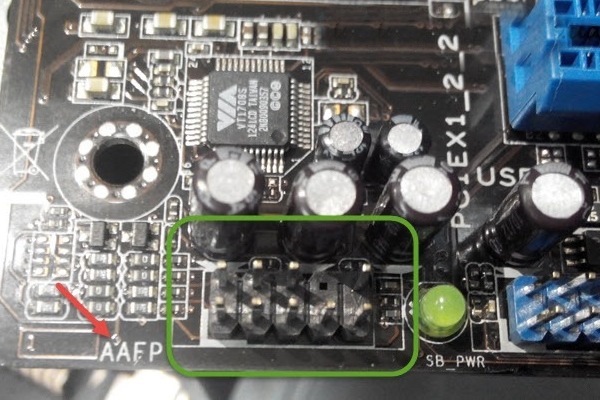
Front panel audio connector (10-1 pin AAFP)
This connector is for a chassis-mounted front panel audio I/O module that supports
either HD Audio or legacy AC`97 audio standard. Connect one end of the front panel
audio I/O module cable to this connector.
P5G41T-M LX2/GB/LPT Front panel audio connector
• We recommend that you connect a high-definition front panel audio module to this
connector to avail of the motherboard’s high-definition audio capability.
• If you want to connect a high-definition front panel audio module to this connector, set
the Front Panel Type item in the BIOS setup to [HD Audio]. If you want to connect an
AC’97 front panel audio module to this connector, set the item to [AC97]. By default, this
connector is set to [HD Audio]. See section 2.4.2 Chipset for details.
Chassis intrusion connector (4-1 pin CHASSIS)
This connector is for a chassis-mounted intrusion detection sensor or switch. Connect
one end of the chassis intrusion sensor or switch cable to this connector. The chassis
intrusion sensor or switch sends a high-level signal to this connector when a chassis
component is removed or replaced. The signal is then generated as a chassis intrusion
By default, the pins labeled “Chassis Signal” and “GND” are shorted with a jumper cap.
Remove the jumper caps only when you intend to use the chassis intrusion detection
P5G41T-M LX2/GB/LPT Chassis intrusion connector
The Chassis intrusion connector is an optional item for P5G41T-M LX2 and
Передняя панель на корпусе системного блока никак не связана с остальными «внутренностями» компьютера. Значит, при ручном отключении с целью чистки или, что немного сложнее, при замене материнской платы, придётся самостоятельно подключать фронтальную панель. Далее будет в подробностях рассказано, как сделать это максимально правильно.
Этапы подключения передней панели к материнской плате
Рассмотрим основные моменты в подключении фронтальной панели к «материнке»:
Этап 1
Первым делом необходимо найти основной шлейф с 4 (иногда 5-6) штекерами. Возможна некоторая разница в названиях, цвете и т. д.
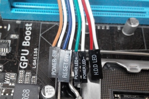
Расположенные на фото сверху штекеры подразумевают собой следующее:
- POWERSW (или PWRBTN) – активирует манипуляции с кнопкой включения/выключения компьютера на панели.
- H.D.D.LED (или HDLED) – лампочка, мигающая при работе жёсткого диска.
- POWERLED + и – (или PLED) – лампочка на кнопке включения/отключения компьютера; если компьютер работает, то горит, и наоборот; может быть цельным штекером.
- RESTARTSW (или RESET) – активирует кнопку перезагрузки компьютера.
- SPEAKER – небольшой динамик, издающий писк, если наблюдаются проблемы в работе компьютера.
Названия этих штекеров могут различаться, но не сильно. Например, вместо POWERSW может быть указано PW. А вместо RESTARTSW – просто RES. Сравнивая первые буквы названия штекеров и разъёмов, можно без труда понять, какой штекер куда должен подключаться. Также помогают цвета, которые, зачастую, соответствуют цвету кабелей от штекеров. Но в первую очередь нужно сравнивать именно названия, следом – цвета, ведь они могут различаться, в отличие от названий.
Этап 2
Вставлять штекеры необходимо в одно большое гнездо (FRONTPANEL или F_PANEL) на краю материнской платы. Обычно оно выглядит вот так:
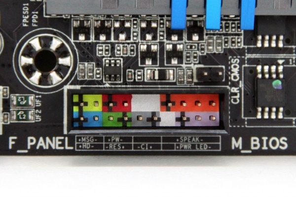
Чтобы подсоединить провода в разъёмы правильной стороной, можно просто посмотреть на сам штекер. Если в нём не будет хватать одного контакта (железная «спица»), то присоединять нужно этим местом, в соответствии с другим пустым местом на материнской плате, в разъёме. Также могут помочь боковые крепления на некоторых гнёздах и штекерах (крепления должны быть на одной стороне). Дополнительно можно ориентироваться по цветам в разъёме или визуальным подсказкам в виде блестящих контактов и т. п. Как правило, штекеры подсоединяются надписью «на себя» или в сторону надписей на материнской плате (схеме).
Внизу, под цветными разъёмами, схематично указаны (подписаны) места, куда нужно подключать штекеры. Например, согласно схеме под разъёмами, отвечающий за кнопку включения компьютера штекер (POWERSW) следует подсоединить в красное гнездо (второе слева, сверху, подписано как PW). Все остальные провода присоединяются в указанные на схеме места соответствующим образом.
В сопроводительной к компьютеру документации, если она имеется, также есть подсказки по подключению штекеров в гнёзда. Выглядят данные подсказки так:
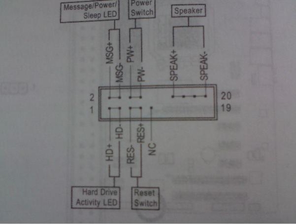
Как видно на рисунке, в документах даже расшифровываются названия штекеров и сокращений на схеме. Например, RES – ResetSwitch (рус. «кнопка перезагрузки») и т. д.
Этап 3
Штекеры, отвечающие за работу USB-портов на передней панели, подключаются чуть иначе и проще. Выглядит USB-штекер — вот так:
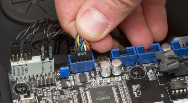
Разъём для данного штекера может иметь следующие названия:
- F_USB1/F_USB2;
- USB1/USB2;
- или все гнёзда для этого штекера могут называться просто USB.
Не имеет значения, куда будет подключаться провод, так как все USB-гнёзда полностью идентичны. За исключением USB 3.0. Если на передней панели имеется именно такой USB-штекер, то и разъём на материнской плате нужно искать с соответствующим названием. Зачастую именно так он и называется – USB 3.0, но могут быть и исключения в виде F_USB30 и т. д.
Этап 4
Подключение звука (наушники/микрофон) на фронтальной панели происходит идентично описанным ранее процессам.
Берётся штекер из передней панели с названием AC97 или HDAUDIO и вставляется в разъём с соответствующей надписью:
Если звук так и не появился, возможно, проблема кроется в BIOS. Перезагрузив компьютер и «попав» в систему BIOS, следует проверить фронтальную панель и её характеристики. Иногда бывает, что подключён штекер HDAUDIO, а BIOS распознал подключённое устройство как AC 97. Решается данный недочёт изменением в BIOSе неправильного драйвера на соответствующий подключённому в материнской плате.
Видео-инструкция по подключению фронтальной панели к «материнке»
В следующем видео на наглядном примере и во всех деталях объясняется процесс присоединения штекеров в разъёмы на материнской плате.
Страница 14: Asus p5g41-m lx, P5g41-m lx, Usbpw5-8, Usbpw1-4, Kbpwr

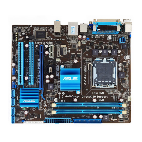
Формат материнской платы
Для установки процессора выполните следующее:
1.
Нажмите на удерживающий рычаг большим пальцем (А), затем перемещайте его влево
(В) до тех пор, пока он не высвободится из-под фиксирующего язычка.
Источник
Инструкция и руководство для
Asus P5G41C-M LX на русском на испанском на французском на итальянском на чешском на немецком на польском
41 страница подробных инструкций и пользовательских руководств по эксплуатации
Asus p5g41t-m lx2/gb + xeon e5450 — быстрый курс по установке ксеона 🙂
ОБЗОР МАТЕРИНСКОЙ ПЛАТЫ Asus p5g41t m lx2 v2
Материнская плата c AliExpress LGA 775 ddr3 ( Asus p5p41t le )
Разгон Xeon E5450 на Asus P5G41T-MLX
Asus P5G41C-M LX 775 Socket Anakarta & Xeon E5450 CPU (İŞLEMCİ) MONTAJ ve Yükleme
Asus P5G41C-M LX & XEON X5472 FSB1600 CPU UYARLAMA-MONTAJ YÜKLEME-BIOS
Asus P5G41C-M LX & Xeon X5460 CPU (3.16Ghz.) SYSTEM UPDATE
Asus P5G41C M LX Mother Board
Français Deutsh Italiano Español Русский Português Polski Če.
P5g41c-m lx, Motherboard, Quick start guide
Quick Start Guide
2010 ASUSTeK COMPUTER INC.
All Rights Reserved
Installer le cpu, Layout de la carte mère, Français
Asus p5g41c-m lx a b, F_panel, P5g41c-m lx, Usbpw5-8, Usbpw1-4, Kbpwr
ASUS P5G41C-M LX
Installer le CPU
Pour installer le CPU :
1. Pressez le levier avec votre pouce (A) et déplacez-le vers la gauche (B)
jusqu’à ce qu’il soit libéré de son onglet de rétention.
Layout de la carte mère
Ce côté doit être face à vous.
DDR3 DIMM_A1 (64bit, 240-pin module)
DDR2 DIMM_A1 (64bit, 240-pin module)
DDR3 DIMM_B1 (64bit, 240-pin module)
DDR2 DIMM_B1 (64bit, 240-pin module)

Mémoire système, Français
ASUS P5G41C-M LX
2. Soulevez le levier dans un angle de 135º.
3. Soulevez la plaque avec votre pouce et votre index à un angle de 100º, puis
enlevez le couvercle PnP de la plaque.
4. Placez le CPU sur le socket, en vous assurant que la marque en forme de
triangle doré est placée en bas à gauche du socket. Les ergots d’alignement
du socket doivent correspondre aux encoches du CPU.
5. Refermez la plaque, puis pressez le levier jusqu’à ce qu’il se loge dans le
loquet de rétention.
• Pour éviter d’endommager les broches du socket, ne retirez le couvercle
PnP que lors de l’installation d’un CPU.
• Veuillez garder le couvercle en cas de retour du produit.
• La garantie de ce produit ne couvre pas les dommages causés aux
broches du socket.
Vous pouvez installer des modules mémoire DDR3 non tamponnés et non ECC de
512Mo, 1Go, 2Go et 4Go dans les slots noirs ou des modules mémoire DDR2 non
tamponnés et non ECC de 512Mo, 1Go, 2Go et 4Go dans les slots bleus.
• N’utilisez pas des modules mémoire DDR3 et DDR2 simultanément.
• Vous pouvez installer des modules mémoire de tailles variables dans le
Canal A et B. Le système mappe la taille totale du canal de plus petite taille
pour les configurations dual-channel. Tout excédant de mémoire du canal
le plus grand est alors mappé pour fonctionner en single-channel.
• Installez toujours des modules mémoire avec une latence CAS identique.
Pour obtenir une compatibilité optimale, il vous est recommandé de vous
équiper des modules de mémoire auprès du même vendeur.
• En raison des limitations d’adressage mémoire sur les systèmes
d’exploitation Windows 32-bits, lorsque vous installez 4Go ou plus de
mémoire sur cette carte mère, le montant de mémoire utilisable par le
système d’exploitation sera de 3 Go ou moins. Pour une utilisation effective
de la mémoire, vous pouvez :
Utiliser un maximum de 3 Go lors de l’utilisation d’un système
Installer un système d’exploitation Windows 64-bits si vous souhaitez
installer 4 Go ou plus de mémoire sur cette carte mère.
• Cette carte mère ne supporte pas les modules mémoire composés de
puces mémoire de 256 Mo ou moins.
DDR3_A1 et DDR2_A1
DDR3_B1 et DDR2_B1

Informations du bios, Informations sur le dvd de support, Français
ASUS P5G41C-M LX
Informations du BIOS
Utilisez le programme de configuration du BIOS pour mettre à jour le BIOS ou
configurer ses paramètres. Les écrans BIOS comprennent les clés de navigation
et une courte aide en ligne pour vous guider. Si vous rencontrez des problèmes
liés au système ou si le système devient instable une fois que vous aurez modifié
les paramètres, chargez les Paramètres de Réglage Par Défaut. Rendez visite au
site web d’ASUS (www.asus.com) pour obtenir les mises à jour.
Pour accéder au Setup lors du démarrage:
Pressez lors du Test Automatique de Démarrage (POST : Power-On
Self Test ). Si vous ne pressez pas la touche , le POST continuera son
programme de test.
Pour accéder au programme de configuration du BIOS après le POST :
• Redémarrez le système en pressant + + , puis pressez
lors du POST, ou
• Pressez le bouton de réinitialisation situé sur le châssis puis pressez
lors du POST, ou
• Eteignez et rallumez le système puis pressez lors du POST.
Pour mettre à jour le BIOS avec ASUS EZ Flash 2 :
Démarrez le système et appuyez sur + lors du POST pour lancer EZ
Flash 2. Insérez un disque flash USB contenant le dernier fichier image du BIOS.
EZ Flash 2 lance le processus de mise à jour du BIOS et redémarre le système
automatiquement une fois terminé.
Pour restaurer le BIOS avec CrashFree BIOS 3 :
Démarrez le système. Si le BIOS est corrompu, l’outil de restauration automatique
CrashFree BIOS 3 vérifiera la présence du fichier du BIOS sur le lecteur optique
et le disque flash USB. Connectez un disque flash USB ou insérez le DVD de
support dans le lecteur optique contenant le dernier fichier image du BIOS ou celui
d’origine. Redémarrez le système une fois le processus de restauration du BIOS
Informations sur le DVD de support
Cette carte mère supporte les systèmes d’exploitation Windows
Installez toujours la dernière version d’OS et les mises à jour correspondantes de
manière à profiter pleinement des caractéristiques de votre matériel.
Le DVD de support livré avec la carte mère contient les pilotes, les applications
logicielles, et les utilitaires que vous pouvez installer pour tirer partie de toutes les
fonctions de la carte mère.
’Exécution automatique n’est pas activée sur votre ordinateur, parcourez
le contenu du DVD de support pour localiser le fichier ASSETUP.EXE dans le
répertoire BIN. Double-cliquez sur
ASSETUP.EXE pour lancer le DVD.

Motherboard-layout 2. installieren der cpu, Deutsch, Asus p5g41c-m lx a b
F_panel, P5g41c-m lx, Usbpw5-8, Usbpw1-4, Kbpwr
ASUS P5G41C-M LX
Installieren der CPU
So installieren Sie den Prozessor:
1. Drücken Sie den Arretierhebel mit Ihrem Daumen (A) und schieben Sie ihn nach
links (B), bis er vom Halteriegel losgelassen wird.
Источник
-
Contents
-
Table of Contents
-
Bookmarks
Quick Links
Related Manuals for Asus P5G41T-M LX
Summary of Contents for Asus P5G41T-M LX
-
Page 1
P5G41T-M LX… -
Page 2
Product warranty or service will not be extended if: (1) the product is repaired, modified or altered, unless such repair, modification of alteration is authorized in writing by ASUS; or (2) the serial number of the product is defaced or missing. -
Page 3: Table Of Contents
Welcome! ………………1-1 Package contents …………….. 1-1 Special features …………….1-1 1.3.1 Product highlights …………1-1 1.3.2 Innovative ASUS features ……….1-2 Before you proceed …………..1-4 Motherboard overview …………..1-5 1.5.1 Placement direction …………1-5 1.5.2 Screw holes …………..1-5 1.5.3…
-
Page 4
Chapter 2: BIOS information Managing and updating your BIOS ……….2-1 2.1.1 ASUS Update utility …………2-1 2.1.2 ASUS EZ Flash 2 …………2-2 2.1.3 ASUS CrashFree BIOS ……….. 2-3 BIOS setup program …………..2-4 2.2.1 BIOS menu screen …………2-5 2.2.2… -
Page 5
Boot Device Priority …………2-17 2.6.2 Boot Settings Configuration ………. 2-17 2.6.3 Security …………….. 2-18 Tools menu …………….. 2-20 2.7.1 ASUS EZ Flash 2 …………2-20 2.7.2 Express Gate [Auto] …………2-20 2.7.3 AI NET 2……………. 2-20 Exit menu ………………2-21… -
Page 6: Notices
This class B digital apparatus complies with Canadian ICES-003. ASUS Recycling/Takeback Services ASUS recycling and takeback programs come from our commitment to the highest standards for protecting our environment. We believe in providing solutions for you to be able to responsibly recycle our products, batteries, other components as well as the packaging materials.
-
Page 7: Safety Information
Complying with the REACH (Registration, Evaluation, Authorisation, and Restriction of Chemicals) regulatory framework, we published the chemical substances in our products at ASUS REACH website at http://csr.asus.com/english/REACH.htm. DO NOT throw the motherboard in municipal waste. This product has been designed to enable proper reuse of parts and recycling.
-
Page 8: About This Guide
Refer to the following sources for additional information and for product and software updates. ASUS websites The ASUS website provides updated information on ASUS hardware and software products. Refer to the ASUS contact information. Optional documentation Your product package may include optional documentation, such as warranty flyers, that may have been added by your dealer.
-
Page 9: P5G41T-M Lx Specifications Summary
— 2 x 240-pin DIMM sockets support unbuffered non-ECC 1333(O.C.)/1066/800 MHz DDR3 memory modules — Supports up to 8GB system memory * Refer to www.asus.com for the latest Memory QVL (Qualified Vendors Lists). ** When you install a total memory of 4GB or more, Windows ®…
-
Page 10
P5G41T-M LX specifications summary ASUS unique ASUS CrashFree BIOS 3 features ASUS AI NET 2 ASUS Q-Fan ASUS EZ Flash 2 ASUS MyLogo 2 ASUS Anti-Surge Protection ASUS Turbo Key ASUS Express Gate ASUS EPU-L Back panel I/O ports 1 x PS/2 keyboard port… -
Page 11: Chapter 1: Product Introduction
® The motherboard delivers a host of new features and latest technologies, making it another standout in the long line of ASUS quality motherboards! Before you start installing the motherboard, and hardware devices on it, check the items in your package with the list below.
-
Page 12: Innovative Asus Features
Turbo Key ASUS Turbo Key allows you to turn the PC power button into an overclocking button. After you easy setup, Turbo Key boosts performances without interrupting ongoing work or games, simply through pressing the button.
-
Page 13: Asus Express Gate
BIOS file using the bundled support DVD or USB flash disk that contains the latest BIOS file. ASUS EZ Flash 2 ASUS EZ Flash 2 is a utility that allows you to update the BIOS without using an OS-based utility. ASUS AI NET2…
-
Page 14: Before You Proceed
Before you proceed Take note of the following precautions before you install motherboard components or change any motherboard settings. • Unplug the power cord from the wall socket before touching any component. • Before handling components, use a grounded wrist strap or touch a safely grounded object or a metal object, such as the power supply case, to avoid damaging them due to static electricity.
-
Page 15: Motherboard Overview
Screw holes Place six screws into the holes indicated by circles to secure the motherboard to the chassis. Do not overtighten the screws! Doing so can damage the motherboard. Place this side towards the rear of the chassis ASUS P5G41T-M LX…
-
Page 16: Motherboard Layout
1.5.3 Motherboard layout 1.5.4 Layout contents Connectors/Jumpers/Slots/LED Page Connectors/Jumpers/Slots/LED Page Keyboard power (3-pin KBPWR) 1-19 Serial ATA connectors (7-pin SATA1-4) 1-24 ATX power connectors (24-pin EATXPWR, 1-23 USB connectors (10-1 pin USB56, USB78) 1-24 4-pin ATX12V) USB device wake-up (3-pin USBPW1-4, 3-pin 1-19 System panel connector (10-1 pin F_PANEL) 1-26…
-
Page 17: Central Processing Unit (Cpu)
Contact your retailer immediately if the PnP cap is missing, or if you see any damage to the PnP cap/socket contacts/motherboard components. ASUS will shoulder the cost of repair only if the damage is shipment/transit-related. • Keep the cap after installing the motherboard. ASUS will process Return Merchandise Authorization (RMA) requests only if the motherboard comes with the cap on the LGA775 socket.
-
Page 18
Press the load lever with your thumb Retention tab (A), then move it to the left (B) until it is released from the retention tab. To prevent damage to the socket pins, do not remove the PnP cap unless you are installing a CPU. Load lever Lift the load lever in the direction of the PnP cap… -
Page 19
To prevent contaminating the paste, DO NOT spread the paste with your finger directly. Close the load plate (A), then push the load lever (B) until it snaps into the retention tab. ASUS P5G41T-M LX… -
Page 20: Installing The Cpu Heatsink And Fan
1.6.2 Installing the CPU heatsink and fan The Intel LGA775 processor requires a specially designed heatsink and fan assembly to ® ensure optimum thermal condition and performance. • When you buy a boxed Intel processor, the package includes the CPU fan and ®…
-
Page 21: Uninstalling The Cpu Heatsink And Fan
Disconnect the CPU fan cable from the connector on the motherboard. Rotate each fastener counterclockwise. Pull up two fasteners at a time in a diagonal sequence to disengage the heatsink and fan assembly from the motherboard. ASUS P5G41T-M LX 1-11…
-
Page 22: System Memory
Carefully remove the heatsink and fan assembly from the motherboard. Rotate each fastener clockwise to ensure correct orientation when reinstalling. System memory 1.7.1 Overview The motherboard comes with two Double Data Rate 3 (DDR3) Dual Inline Memory Modules (DIMM) sockets. The figure illustrates the location of the DDR3 DIMM sockets: Channel Sockets Channel A…
-
Page 23: Memory Configurations
SEC 901 HCF8 K4B1G0846E — • • SAMSUNG M378B5273BH1-CF8 4096MB DS SAMSUNG 846 K4B2G0846B-HCF8 • • Elixir M2Y2G64CBHA9N-BE 2048MB DS — 7-7-7-20 — • • Kingtiger 2GB DIMM PC3-8500 2048MB DS Hynix H5TQ1G83AFP G7C • • ASUS P5G41T-M LX 1-13…
-
Page 24
DDR3-1333 MHz (O.C.) capability DIMM socket Chip support (Optional) Vendor Part No. Size Chip NO. Timing Voltage Brand A-Data AD31333001GOU 1024MB A-Data AD30908C8D-151C E0906 • A-Data AD31333G001GOU 3072MB(Kit of 3) SS 8-8-8-24 1.65-1.85V • A-Data AD31333002GOU 2048MB A-Data AD30908C8D-151C E0903 •… -
Page 25
• A*: Supports one module inserted into any slot as Single-channel memory configuration. • B*: Supports one pair of modules inserted into both the blue slots as one pair of Dual-channel memory configuration. Visit the ASUS website at www.asus.com for the latest QVL. ASUS P5G41T-M LX 1-15… -
Page 26: Installing A Dimm
1.7.3 Installing a DIMM Unplug the power supply before adding or removing DIMMs or other system components. Failure to do so can cause severe damage to both the motherboard and the components. To install a DIMM: DIMM notch Press the retaining clips outward to unlock a DIMM socket.
-
Page 27: Expansion Slots
This motherboard supports PCI Express x1 network cards, SCSI cards, and other cards that comply with the PCI Express specifications. 1.8.5 PCI Express x16 slot This motherboard supports a PCI Express x16 graphics card that complies with the PCI Express specifications. ASUS P5G41T-M LX 1-17…
-
Page 28: Clear Rtc Ram
Jumpers Clear RTC RAM (3-pin CLRTC) This jumper allows you to clear the Real Time Clock (RTC) RAM in CMOS. You can clear the CMOS memory of date, time, and system setup parameters by erasing the CMOS RTC RAM data. The onboard button cell battery powers the RAM data in CMOS, which include system setup information such as system passwords.
-
Page 29
• The USB device wake-up feature requires a power supply that can provide 500mA on the +5VSB lead for each USB port; otherwise, the system would not power up. • The total current consumed must NOT exceed the power supply capability (+5VSB) whether under normal condition or in sleep mode. ASUS P5G41T-M LX 1-19… -
Page 30: Connectors
1.10 Connectors 1.10.1 Rear panel connectors PS/2 mouse port (green). This port is for a PS/2 mouse. Parallel port. This 25-pin port connects a parallel printer, a scanner, or other devices. LAN (RJ-45) port. This port allows Gigabit connection to a Local Area Network (LAN) through a network hub.
-
Page 31: Internal Connectors
Front Panel Type item in the BIOS setup to [HD Audio]. If you want to connect an AC’97 front panel audio module to this connector, set the item to [AC97]. By default, this connector is set to [HD Audio]. See section 2.4.3 Chipset for details. ASUS P5G41T-M LX 1-21…
-
Page 32
IDE connector (40-1 pin PRI_IDE) The onboard IDE connector is for the Ultra DMA 100/66/33 signal cable. There are three connectors on each Ultra DMA 100/66/33 signal cable: blue, black, and gray. Connect the blue connector to the motherboard’s IDE connector, then select one of the following modes to configure your device. -
Page 33
The system may become unstable or may not boot up if the power is inadequate. • If you are uncertain about the minimum power supply requirement for your system, refer to the Recommended Power Supply Wattage Calculator at http://support.asus. com/PowerSupplyCalculator/PSCalculator.aspx?SLanguage=en-us for details. ASUS P5G41T-M LX… -
Page 34
Serial ATA connectors (7-pin SATA1-4) These connectors are for the Serial ATA signal cables for Serial ATA 3Gb/s hard disk and optical disk drives. The Serial ATA 3Gb/s is backward compatible with Serial ATA 1.5Gb/s specification. The data transfer rate of the Serial ATA 3Gb/s is faster than the standard parallel ATA with 133 MB/s (Ultra DMA133). -
Page 35
These are not jumpers! Do not place jumper caps on the fan connectors! Only the 4-pin CPU fan supports the ASUS Q-FAN feature. Digital audio connector (4-1 pin SPDIF_OUT) This connector is for an additional Sony/Philips Digital Interface (S/PDIF) port. Connect the S/PDIF Out module cable to this connector, then install the module to a slot opening at the back of the system chassis. -
Page 36: System Panel Connector
System panel connector (10-1 pin PANEL) This connector supports several chassis-mounted functions. • System power LED (2-pin PLED) This 2-pin connector is for the system power LED. Connect the chassis power LED cable to this connector. The system power LED lights up when you turn on the system power, and blinks when the system is in sleep mode.
-
Page 37: Software Support
The contents of the Support DVD are subject to change at any time without notice. Visit the ASUS website at www.asus.com for updates. To run the Support DVD Place the Support DVD to the optical drive.
-
Page 38
1-28 Chapter 1: Product introduction… -
Page 39: Managing And Updating Your Bios
BIOS in the future. Copy the original motherboard BIOS using the ASUS Update utility. 2.1.1 ASUS Update utility The ASUS Update is a utility that allows you to manage, save, and update the motherboard BIOS in Windows environment. ®…
-
Page 40: Asus Ez Flash 2
Follow the onscreen instructions to complete the updating process. 2.1.2 ASUS EZ Flash 2 The ASUS EZ Flash 2 feature allows you to update the BIOS without using an OS-based utility. Before you start using this utility, download the latest BIOS file from the ASUS website at www.asus.com.
-
Page 41: Asus Crashfree Bios
2.1.3 ASUS CrashFree BIOS The ASUS CrashFree BIOS is an auto recovery tool that allows you to restore the BIOS file when it fails or gets corrupted during the updating process. You can restore a corrupted BIOS file using the motherboard support DVD or a removable device that contains the updated BIOS file.
-
Page 42: Bios Setup Program
• The BIOS setup screens shown in this section are for reference purposes only, and may not exactly match what you see on your screen. • Visit the ASUS website at www.asus.com to download the latest BIOS file for this motherboard.
-
Page 43: Bios Menu Screen
For configuring options for special functions. Exit For selecting the exit options and loading default settings. To select an item on the menu bar, press the right or left arrow key on the keyboard until the desired item is highlighted. ASUS P5G41T-M LX…
-
Page 44: Navigation Keys
2.2.3 Navigation keys At the bottom right corner of a menu screen are the navigation keys for that particular menu. Use the navigation keys to select items in the menu and change the settings. Some of the navigation keys differ from one screen to another. 2.2.4 Menu items The highlighted item on the menu bar displays the specific items for that menu.
-
Page 45: Main Menu
IDE device type. Select CDROM if you are specifically configuring a CD-ROM drive. Select ARMD (ATAPI Removable Media Device) if your device is either a ZIP, LS-120, or MO drive. Configuration options: [Not Installed] [Auto] [CDROM] [ARMD] This item does not appear when you select the SATA 1/2/3/4 devices. ASUS P5G41T-M LX…
-
Page 46: Storage Configuration
LBA/Large Mode [Auto] Enables or disables the LBA mode. Setting to [Auto] enables the LBA mode if the device supports this mode, and if the device was not previously formatted with LBA mode disabled. Configuration options: [Disabled] [Auto] Block (Multi-sector Transfer) M [Auto] Enables or disables data multi-sectors transfers.
-
Page 47: System Information
Select either one of the preset overclocking configuration options: Manual — allows you to individually set overclocking parameters. Auto — loads the optimal settings for the system. Overclock Profile — loads overclocking profiles with optimal parameters for stability when overclocking. ASUS P5G41T-M LX…
-
Page 48
The following two items appear only when you set the AI Overclocking item to [MANUAL]. CPU Frequency [xxx] Displays the frequency sent by the clock generator to the system bus and PCI bus. The value of this item is auto-detected by the BIOS. Use the <+> and <-> keys to adjust the CPU frequency. -
Page 49: Cpu Configuration
Virtualization Technology. Virtualization enhanced by Intel ® ® Virtualization Technology allows a platform to run multiple operating systems and applications in independent partitions. With virtualization, one computer system can function as multiple virtual systems. Configuration options: [Enabled] [Disabled] ASUS P5G41T-M LX 2-11…
-
Page 50: Chipset
CPU TM Function [Enabled] Enables or disables Intel CPU Thermal Monitor (TM) function, a CPU overheating protection ® function. When enabled, the CPU core frequency and voltage are reduced when the CPU overheats. Configuration options: [Disabled] [Enabled] Execute-Disable Bit Capability [Enabled] Allows you to enable or disable the No-Execution Page Protection Technology.
-
Page 51: Onboard Devices Configuration
Parallel Port ECP DMA. Configuration options: [DMA0] [DMA1] [DMA3] EPP Version [1.9] Appears only when the Parallel Port Mode is set to [EPP]. Configuration options: [1.9] [1.7] Parallel Port IRQ [IRQ7] Allows you to select parallel port IRQ. Configuration options: [IRQ5] [IRQ7] ASUS P5G41T-M LX 2-13…
-
Page 52: Usb Configuration
2.4.5 USB Configuration The items in this menu allows you to change the USB-related features. Select an item then press <Enter> to display the configuration options. The Module Version and USB Devices Enabled items show the auto-detected values. If no USB device is detected, the item shows None.
-
Page 53: Pci Pnp
Application-Specific Integrated Circuit (ASIC). When set to Enabled, the ACPI APIC table pointer is included in the RSDT pointer list. Configuration options: [Disabled] [Enabled] 2.5.4 Anti Surge Support [Enabled] Allows you to enable or disable the Anti-Surge protection. Configuration options: [Disabled] [Enabled] ASUS P5G41T-M LX 2-15…
-
Page 54: Apm Configuration
2.5.5 APM Configuration Restore on AC Power Loss [Power Off] When set to [Power Off], the system goes into off state after an AC power loss. When set to [Power On], the system goes on after an AC power loss. When set to [Last State], the system goes into either off or on state, whatever the system state was before the AC power loss.
-
Page 55: Boot Menu
Configuration options: [Removable Dev.] [Hard Drive] [ATAPI CD-ROM] [Disabled] • To select the boot device during system startup, press <F8> when ASUS Logo appears. • To access Windows OS in Safe Mode, do any of the following: ®…
-
Page 56: Security
Full Screen Logo [Enabled] This allows you to enable or disable the full screen logo display feature. Configuration options: [Disabled] [Enabled] Set this item to [Enabled] to use the ASUS MyLogo2 feature. ™ AddOn ROM Display Mode [Force BIOS] Sets the display mode for option ROM. Configuration options: [Force BIOS] [Keep Current] Bootup Num-Lock [On] Allows you to select the power-on state for the NumLock.
-
Page 57: Change User Password
Password Check [Setup] When set to [Setup], BIOS checks for user password when accessing the Setup utility. When set to [Always], BIOS checks for user password both when accessing Setup and booting the system. Configuration options: [Setup] [Always] ASUS P5G41T-M LX 2-19…
-
Page 58: Tools Menu
2.7.1 ASUS EZ Flash 2 Allows you to run ASUS EZ Flash 2. When you press <Enter>, a confirmation message appears. Use the left/right arrow key to select between [Yes] or [No], then press <Enter> to confirm your choice. See section 2.1.2 ASUS EZ Flash 2 for details.
-
Page 59: Exit Menu
When you select this option or if you press <F5>, a confirmation window appears. Select OK to load default values. Select Exit & Save Changes or make other changes before saving the values to the non-volatile RAM. ASUS P5G41T-M LX 2-21…
-
Page 60
2-22 Chapter 2: BIOS information… -
Page 61: Asus Contact Information
+1-510-739-3777 +1-510-608-4555 Web site usa.asus.com Technical Support Telephone +1-812-282-2787 Support fax +1-812-284-0883 Online support support.asus.com ASUS COMPUTER GmbH (Germany and Austria) Address Harkort Str. 21-23, D-40880 Ratingen, Germany +49-2102-959911 Web site www.asus.de Online contact www.asus.de/sales Technical Support Telephone (Component) +49-1805-010923*…
Инструкция и руководство для
Asus P5G41-M LX на русском на испанском на французском на итальянском на чешском на немецком на польском


41 страница подробных инструкций и пользовательских руководств по эксплуатации
 12:31
12:31
Сборка бюджетного игрового компьютера
 06:52
06:52
Asus p5g41t-m lx2/gb + xeon e5450 — быстрый курс по установке ксеона
 13:35
13:35
ASUS P5G41-M LX XEON X5472 1600FSB+BECHMARK TEST+GTA V GAME TEST
 03:49
03:49
ОБЗОР МАТЕРИНСКОЙ ПЛАТЫ Asus p5g41t m lx2 v2
 08:22
08:22
Материнская плата c AliExpress LGA 775 ddr3 ( Asus p5p41t le )
 12:44
12:44
Разгон Xeon E5450 на Asus P5G41T-MLX
 17:56
17:56
XEON E5462 CPU 1600FSB-ASUS P5G41-M LX GAME TEST-BENCHMARK TEST
 02:53
02:53
Разгон Xeon e5450(x5450) на g41 чипсете
Français Deutsh Italiano Español Русский Português Polski Če…
P5g41-m lx, Motherboard, Quick start guide
- Изображение
- Текст
Français
Deutsh
Italiano
Español
Русский
Português
Polski
Česky
Magyar
Български
Română
Srpski
Türkçe
Quick Start Guide
First Edition
February 2009
Copyright © 2009 ASUSTeK COMPUTER INC.
All Rights Reserved
U4972
P5G41-M LX
Motherboard

Installer le cpu, Layout de la carte mère, Français
Asus p5g41-m lx, F_panel, P5g41-m lx, Usbpw5-8, Usbpw1-4, Kbpwr
- Изображение
- Текст
2
Français
ASUS P5G41-M LX
2.
Installer le CPU
Pour installer le CPU :
1. Pressez le levier avec votre pouce (A) et déplacez-le vers la gauche (B)
jusqu’à ce qu’il soit libéré de son onglet de rétention.
1.
Layout de la carte mère
A
B
Languette de
retenue
Levier
Ce côté doit être face à vous.
Capuchon PnP
P5G41-M LX
PCIEX16
PCIEX1_1
PCIEX1_2
PCI1
PRI_IDE
USB56
USB78
F_PANEL
AAFP
IC
S
9LRS954
ATX12V
EATXPW
R
CPU_FAN
Intel
®
G41
Lithium Cell
CMOS Power
Super
I/O
AUDIO
ALC
662-VC1
RTL
8103EL
KBMS
8Mb
BIOS
SB_PWR
CLRTC
USBPW1-4
USBPW5-8
KBPWR
SPEAKER
18.3cm(7.2in)
24.4cm(9.6in)
LGA775
Intel
®
ICH7
DDR2 DIMM_A1 (64bit, 240-pin module)
DDR2 DIMM_B1 (64bit, 240-pin module)
VG
A
COM1
LAN1_USB12
USB34
SATA1 SATA3
SATA2
SATA4
CHA_FAN
1 2
2 3
Normal
(Default)
Clear RTC
CLRTC
2
1
2 3
+5V
(Default)
+5VSB
USBPW5-8
2
1
2
3
+5V
+5VSB
(Default)
USBPW1-4
2
1
2 3
+5V
(Default)
+5VSB
KBPWR
PIN 1
PWR BTN
PLED
+
PLED
—
PWR
GND
HD_LED
+
HD_LED-
Groun
d
Rese
t
F_PANEL
PLED
+HDLED
RESET

Français
ASUS P5G41-M LX
2. Soulevez le levier dans un angle de 135º.
3. Soulevez la plaque avec votre pouce et votre index à un angle de 100º, puis
enlevez le couvercle PnP de la plaque.
4. Placez le CPU sur le socket, en vous assurant que la marque en forme de
triangle doré est placée en bas à gauche du socket. Les ergots d’alignement
du socket doivent correspondre aux encoches du CPU.
5. Refermez la plaque, puis pressez le levier jusqu’à ce qu’il se loge dans le
loquet de rétention.
• Pour éviter d’endommager les broches du socket, ne retirez le couvercle
PnP que lors de l’installation d’un CPU.
• Veuillez garder le couvercle en cas de retour du produit.
• La garantie de ce produit ne couvre pas les dommages causés aux broches
du socket.
.
Mémoire Système
Vous pouvez installer des DIMM DDR2 GB unbuffered non-ECC de 512 MO, 1 Go,
2 Go et 4 Go dans les sockets.
• Vous pouvez installer des modules mémoire de tailles variables dans le
Canal A et B. Le système mappe la taille totale du canal de plus petite taille
pour les configurations dual-channel. Tout excédant de mémoire du canal
le plus grand est alors mappé pour fonctionner en single-channel.
• Installez toujours des modules mémoire avec une latence CAS identique.
Pour obtenir une compatibilité optimale, il vous est recommandé de vous
équiper des modules de mémoire auprès du même vendeur.
• En raison des limitations d’adressage mémoire sur les systèmes
d’exploitation Windows 32-bits, lorsque vous installez 4Go ou plus de
mémoire sur cette carte mère, le montant de mémoire utilisable par le
système d’exploitation sera de 3 Go ou moins. Pour une utilisation effective
de la mémoire, vous pouvez :
—
Utiliser un maximum de 3 Go lors de l’utilisation d’un système
d’exploitation 32-bits.
—
Installer un système d’exploitation Windows 64-bits si vous
souhaitez installer 4 Go ou plus de mémoire sur cette carte
mère.
• Cette carte mère ne supporte pas les modules mémoire composés de
puces mémoire de 256 Mo ou moins.
Canal
Emplacements
Canal A
DIMM_A1
Canal B
DIMM_B1

Informations du bios, Informations sur le dvd de support, Français
Страница 4
- Изображение
- Текст
4
Français
ASUS P5G41-M LX
4.
Informations du BIOS
Utilisez le programme de configuration du BIOS pour mettre à jour le BIOS ou
configurer ses paramètres. Les écrans BIOS comprennent les clés de navigation
et une courte aide en ligne pour vous guider. Si vous rencontrez des problèmes
liés au système ou si le système devient instable une fois que vous aurez modifié
les paramètres, chargez les Paramètres de Réglage Par Défaut. Rendez visite au
site web d’ASUS (www.asus.com) pour obtenir les mises à jour.
Pour accéder au Setup lors du démarrage:
Pressez <Suppr> lors du Test Automatique de Démarrage (POST : Power-On
Self Test ). Si vous ne pressez pas la touche <Suppr>, le POST continuera son
programme de test.
Pour accéder au programme de configuration du BIOS après le POST :
• Redémarrez le système en pressant <Ctrl> + <Alt> + <Suppr>, puis pressez
<Suppr> lors du POST, ou
• Pressez le bouton de réinitialisation situé sur le châssis puis pressez <Suppr>
lors du POST, ou
• Eteignez et rallumez le système puis pressez <Suppr> lors du POST.
Pour mettre à jour le BIOS avec ASUS EZ Flash 2 :
Démarrez le système et appuyez sur <Alt> + <F2> lors du POST pour lancer EZ
Flash 2. Insérez un disque flash USB contenant le dernier fichier image du BIOS.
EZ Flash 2 lance le processus de mise à jour du BIOS et redémarre le système
automatiquement une fois terminé.
Pour restaurer le BIOS avec CrashFree BIOS :
Démarrez le système. Si le BIOS est corrompu, l’outil de restauration automatique CrashFree
BIOS 3 vérifiera la présence du fichier du BIOS sur le lecteur optique et le disque flash
USB. Connectez un disque flash USB ou insérez le DVD de support dans le lecteur optique
contenant le dernier fichier image du BIOS ou celui d’origine. Redémarrez le système une
fois le processus de restauration du BIOS terminé.
5.
Informations sur le DVD de support
Cette carte mère supporte les systèmes d’exploitation Windows
®
XP / Vista. Installez
toujours la dernière version d’OS et les mises à jour correspondantes de manière à profiter
pleinement des caractéristiques de votre matériel.
Le DVD de support livré avec la carte mère contient les pilotes, les applications logicielles,
et les utilitaires que vous pouvez installer pour tirer partie de toutes les fonctions de la carte
mère.
Si l’Exécution automatique n’est pas activée sur votre ordinateur, parcourez
le contenu du DVD de support pour localiser le fichier ASSETUP.EXE dans le
répertoire BIN. Double-cliquez sur ASSETUP.EXE pour lancer le DVD.

Motherboard-layout 2. installieren der cpu, Deutsch, F_panel
Asus p5g41-m lx, P5g41-m lx, Usbpw5-8, Usbpw1-4, Kbpwr
- Изображение
- Текст
5
ASUS P5G41-M LX
Deutsch
A
B
1.
Motherboard-Layout
2.
Installieren der CPU
So installieren Sie den Prozessor:
1. Drücken Sie den Arretierhebel mit Ihrem Daumen (A) und schieben Sie ihn nach
links (B), bis er vom Halteriegel losgelassen wird.
Ladehebel
Halteriegel
PnP-Kappe
Diese Seite der Cam-Box
sollte zu Ihnen zeigen.
P5G41-M LX
PCIEX16
PCIEX1_1
PCIEX1_2
PCI1
PRI_IDE
USB56
USB78
F_PANEL
AAFP
IC
S
9LRS954
ATX12V
EATXPW
R
CPU_FAN
Intel
®
G41
Lithium Cell
CMOS Power
Super
I/O
AUDIO
ALC
662-VC1
RTL
8103EL
KBMS
8Mb
BIOS
SB_PWR
CLRTC
USBPW1-4
USBPW5-8
KBPWR
SPEAKER
18.3cm(7.2in)
24.4cm(9.6in)
LGA775
Intel
®
ICH7
DDR2 DIMM_A1 (64bit, 240-pin module)
DDR2 DIMM_B1 (64bit, 240-pin module)
VG
A
COM1
LAN1_USB12
USB34
SATA1 SATA3
SATA2
SATA4
CHA_FAN
1 2
2 3
Normal
(Default)
Clear RTC
CLRTC
2
1
2 3
+5V
(Default)
+5VSB
USBPW5-8
2
1
2
3
+5V
+5VSB
(Default)
USBPW1-4
2
1
2 3
+5V
(Default)
+5VSB
KBPWR
PIN 1
PWR BTN
PLED
+
PLED
—
PWR
GND
HD_LED
+
HD_LED-
Groun
d
Rese
t
F_PANEL
PLED
+HDLED
RESET

ASUS P5G41-M LX
Deutsch
.
Arbeitsspeicher
Sie können 512 MB, 1 GB, 2 GB und 4 GB ungepufferte nicht-ECC DDR2 DIMMs in
den DIMM-Sockeln installieren.
2. Heben Sie den Arretierhebel bis zu einem Winkel von 135º hoch.
3. Heben Sie die Deckplatte mit Daumen und Zeigefinger bis zu einem Winkel von
100º hoch, und drücken Sie die PnP-Abdeckung von der Deckplattenaussparung,
um sie zu entfernen.
4. Legen Sie die CPU auf den Sockel. Richten Sie dabei das goldene Dreieck auf
die linke untere Kante des Sockels aus. Die Sockelausrichtungsnase muss in
die CPU-Kerbe einpassen.
5. Schließen Sie die Deckplatte und drücken Sie dann den Arretierhebel, bis er in
den Halteriegel einrastet.
•
Um Schäden an den Sockelpolen zu vermeiden, entfernen Sie bitte die PnP-Abdeckung nicht
vor dem Beginn der CPU-Installation.
•
Bitte bewahren Sie die Abdeckung fär den Fall einer Räckgabe des Produktes auf.
•
Die Produktgarantie deckt keine Beschädigung der Sockelpole ab.
Kanal
Steckplätze
Kanal A
DIMM_A1
Kanal B
DIMM_B1
• Sie können verschiedene Speichergrößen in Channel A und Channel B
installieren. Das System ordnet die gesamte Größe des weniger belegten
Kanals für die Dual-Channel-Konfiguration zu. Der überschüssige Speicher
des höher belegten Kanals wird dann der Single-Channel-Konfiguration
zugeordnet.
• Installieren Sie immer DIMMs mit gleicher CAS-Latenzzeit. Für optimale
Installieren Sie immer DIMMs mit gleicher CAS-Latenzzeit. Für optimale
Kompatibilität wird empfohlen, nur Speichermodule eines Herstellers zu
verwenden.
• Durch die Speicheradressenbeschränkung in 32-Bit-Windows
®
können vom
Betriebssystem nur 3GB oder weniger benutzt werden, selbst wenn 4GB
installiert wurden. Für eine effektive Speichernutzung empfehlen wir Ihnen
folgendes:
— Installieren Sie maximal 3GB Speicher, wenn Sie ein 32-Bit-Windows
Installieren Sie maximal 3GB Speicher, wenn Sie ein 32-Bit-Windows
®
—
betriebssystem benutzen.
— Installieren Sie ein 64-Bit-Windows
®
-betriebssystem, wenn Sie auf dem
Motherboard 4GB oder mehr Speicher installieren wollen.
• Dieses Motherboard unterstützt keine DIMMs, die aus 256 Megabit- (Mb)
Chips oder weniger hergestellt wurden.

7
ASUS P5G41-M LX
Deutsch
4.
BIOS-Informationen
Benutzen Sie das BIOS-Einstellungsprogramm zum aktualisieren des BIOS oder
zur Konfiguration seiner Parameter. Die BIOS-Anzeigen enthalten Navigations-
anleitungen und eine kurze Online-Hilfe, um Ihnen die Verwendung zu erleichtern.
Falls in Ihrem System Probleme auftauchen, oder das System nach dem Verändern
einiger Einstellungen instabil wird, sollten Sie die Standardeinstellungen zurückholen.
Weitere Neuigkeiten finden Sie auf der ASUS-Webseite (www.asus.com).
So öffnen Sie das BIOS-Setup beim Systemstart:
Drücken Sie <Entf> während des Power-On Self-Test (POST). Wenn Sie nicht <Entf>
drücken, fährt der POST mit seiner Routine fort.
So öffnen Sie das Setup nach dem POST:
• Starten Sie das System neu, indem Sie <Strg> + <Alt> + <Entf> drücken, und
drücken Sie dann <Entf> während des POST, oder
• Drücken Sie den Reset-Schalter am Computergehäuse, und drücken Sie dann
<Entf> während des POST, oder
• Schalten Sie das System aus und wieder an, und drücken Sie dann <Entf>
während des POST
Aktualisieren des BIOS mit ASUS EZ Flash 2:
Booten Sie das System neu und drücken <Alt> + <F2> während des POST, um
EZ Flash 2 zu starten. Legen Sie die Diskette, die die neueste BIOS-Datei enthält,
ein. EZ Flash 2 führt den BIOS-Aktualisierungsprozess aus und startet das System
automatisch nach dem Vervollständigen des Prozesses neu.
So stellen Sie das BIOS mit CrashFree BIOS wieder her:
Starten Sie das System. Falls die BIOS-Datei beschädigt ist, sucht das CrashFree
BIOS 3-Wiederherstellungsprogramm nach einer Diskette oder DVD, mit der das BIOS
wieder hergestellt werden kann. Legen Sie die Support-DVD des Motherboards, oder
eine Diskette mit der ursprünglichen oder einer neueren BIOS-Datei ein. Starten Sie
das System neu, wenn das BIOS wieder hergestellt ist.
5.
Software-Unterstützungbg
Das Motherboard unterstützt Windows
®
XP/Vista Betriebssysteme (OS). Installieren
Sie bitte immer die neueste OS-Version und die entsprechenden Updates, um die
Funktionen Ihrer Hardware zu maximieren.
Die mit dem Motherboard gelieferte Support-DVD enthält die Treiber, Anwendungs-
Software und Programme die Sie installieren können, um alle Motherboard-
Funktionen benutzen zu können. Es wird bei aktivierter Autorun-Funktion
automatisch das Treibermenü angezeigt.
Wenn Autorun nicht aktiviert ist, durchsuchen Sie den Inhalt der Support-DVD,
um die Datei ASSETUP.EXE im Ordner BIN zu finden. Doppelklicken Sie auf
das Dateisymbol ASSETUP.EXE, um die DVD auszuführen.

Italiano, F_panel, Asus p5g41-m lx
P5g41-m lx, Usbpw5-8, Usbpw1-4, Kbpwr
- Изображение
- Текст
ASUS P5G41-M LX
Italiano
A
B
1.
Diagramma disposizione scheda madre
2.
Installazione della CPU
Installazione della CPU:
1. Premere la levetta di carico con il pollice (A), poi spostarla e sinistra (B) finché
è liberata dalla linguetta di trattenimento.
Levetta di carico
Linguetta di trattenimento
Copertura PnP
Questo lato del modulo deve essere
rivolto verso sé stessi.
P5G41-M LX
PCIEX16
PCIEX1_1
PCIEX1_2
PCI1
PRI_IDE
USB56
USB78
F_PANEL
AAFP
IC
S
9LRS954
ATX12V
EATXPW
R
CPU_FAN
Intel
®
G41
Lithium Cell
CMOS Power
Super
I/O
AUDIO
ALC
662-VC1
RTL
8103EL
KBMS
8Mb
BIOS
SB_PWR
CLRTC
USBPW1-4
USBPW5-8
KBPWR
SPEAKER
18.3cm(7.2in)
24.4cm(9.6in)
LGA775
Intel
®
ICH7
DDR2 DIMM_A1 (64bit, 240-pin module)
DDR2 DIMM_B1 (64bit, 240-pin module)
VG
A
COM1
LAN1_USB12
USB34
SATA1 SATA3
SATA2
SATA4
CHA_FAN
1 2
2 3
Normal
(Default)
Clear RTC
CLRTC
2
1
2 3
+5V
(Default)
+5VSB
USBPW5-8
2
1
2
3
+5V
+5VSB
(Default)
USBPW1-4
2
1
2 3
+5V
(Default)
+5VSB
KBPWR
PIN 1
PWR BTN
PLED
+
PLED
—
PWR
GND
HD_LED
+
HD_LED-
Groun
d
Rese
t
F_PANEL
PLED
+HDLED
RESET

9
ASUS P5G41-M LX
Italiano
3.
Memoria di sistema
Nelle prese per DIMM, si possono installare moduli di memoria DIMM DDR non-ECC,
senza buffer, da 512 MB, 1 GB, 2 GB e da 4 GB.
2. Sollevare la levetta di carico nella direzione indicata dalla freccia ad un anglo
di 135°.
3. Sollevare la placca di carico con il pollice e l’indice ad un angolo di 100º (A),
poi spingere la copertura PnP dalla placca di carico per rimuoverla (B).
4. Collocare la CPU sopra la presa, assicurandosi che il triangolo dorato si trovi
nell’angolo in basso a sinistra della presa. Il tasto di allineamento della presa
deve adattarsi alla dentellatura della CPU.
5. Chiudere la placca di carico (A), poi spingere la leva di carico (B) finché scatta
nella linguetta di trattenimento.
•
Per evitare di danneggiare i pin, non rimuovere la copertura PnP salvo
si stia installando una CPU.
•
Conservare il cappuccio per eventuali restituzioni del prodotto.
•
La garanzia del prodotto non copre i danni ai pin della presa.
Canale doppio
Prese
Coppia A
DIMM_A1
Coppia B
DIMM_B1
• È possibile installare diversi formati di memoria nei canali A e B. Il sistema
mappa la dimensione totale del canale di dimensione più piccolo per la
configurazione a canale doppio. Qualsiasi accesso alla memoria dal canale
di dimensione maggiore, viene quindi mappato per il funzionamento a canale
singolo.
• Utilizzare e installare sempre moduli DIMM con la stessa latenza CAS. Per
poter garantire la perfetta compatibilità dei moduli, si raccomanda di utilizzare
moduli di memoria acquistati presso lo stesso venditore.
• A causa dei limiti con gli indirizzi di memoria nel sistema operativo Windows®
a 32 bit, quando si installa una memoria da 4GB o più sulla scheda madre, la
memoria effettivamente utilizzabile dal sistema operativa può essere di 3GB
o meno. Per usare in modo efficace la memoria, si raccomanda di eseguire
una delle seguenti azioni:
— Usare 3GB di memoria di sistema al massimo se si utilizza il sistema
Usare 3GB di memoria di sistema al massimo se si utilizza il sistema
operativo Windows® a 32 bit.
— Per installare 4GB di memoria o più sulla scheda madre, installare il
sistema operativo Windows® a 64 bit.
• Questa scheda madre non supporta DIMM da 256 megabit (Mb) o minori.

Informazioni sul bios, Italiano, Supporto per il software
Страница 10
- Изображение
- Текст
10
ASUS P5G41-M LX
Italiano
4.
Informazioni sul BIOS
Usare l’utilità per la configurazione del BIOS per aggiornare il BIOS o configurarne i
parametri. La schermata BIOS include tasti di navigazione ed una concisa guida in
linea. Se si riscontrano problemi con il sistema, oppure se questo diventa instabile
dopo avere modificato le impostazioni, caricare le impostazioni predefinite di
configurazione Setup Defaults. Visitare la pagina Web ASUS (www.asus.com) per
gli aggiornamenti.
Per accedere al Setup all’avvio:
Premere il tasto <Delete> durante il POST (Power On Self Test). Se non si preme il
tasto <Delete>, il POST continua le sue routine di diagnostica.
Per accedere al Setup dopo il POST:
• Riavviare il sistema premendo i tasti <Ctrl> + <Alt> + <Delete>, poi premere il
tasto <Delete> durante il POST, oppure
• Premere il tasto di ripristino sul telaio, poi premere il tasto <Delete> durante il
POST, oppure
• Spegnere e riaccendere il sistema e poi premere il tasto <Delete> durante il
POST
Aggiornare il BIOS con ASUS EZ Flash 2:
Avviare il sistema e premere <Alt> + <F2> nel corso del POST per lanciare EZ Flash 2.
Inserire una memoria flash USB contenente il file con la versione più recente del BIOS.
EZ Flash 2 esegue il processo di aggiornamento del BIOS e riavvia automaticamente
il sistema una volta completato.
Ripristinare il BIOS con CrashFree BIOS :
Avviare il sistema. Se il BIOS è danneggiato, lo strumento per il ripristino automatico
CrashFree BIOS 3 verifica l’unità ottica e la memoria flash USB per verificare la
presenza di un file BIOS in modo da poter procedere al ripristino del BIOS: Inserire
una memoria flash USB o il DVD di supporto che contiene il file con la versione più
recente o originale del BIOS. Riavviare il sistema dopo avere eseguito il ripristino
del BIOS.
5.
Supporto per il software
Questa scheda madre supporta un sistema operativo (OS) Windows
®
XP/Vista.
Installate sempre l’ultima versione OS e gli aggiornamenti corrispondenti, in modo
da massimizzare le funzioni del vostro hardware.
Il DVD di supporto fornito con il pacchetto della scheda madre contiene i driver, le
applicazioni software e le utilità che possono essere installate per poter sfruttare tutte
le caratteristiche della scheda madre. Viene visualizzato automaticamente il menu
Driver se sul computer è attiva l’Esecuzione automatica.
Se sul computer non è attiva ESECUZIONE AUTOMATICA, sfogliare i contenuti
del DVD di supporto per individuare il file ASSETUP.EXE nella cartella BIN.
Fare doppio clic su ASSETUP.EXE per eseguire il DVD.

Комментарии
-
Драйверы
13
-
Инструкции по эксплуатации
6
Языки:
ASUS P5G41T-M LX2/GB/LPT инструкция по эксплуатации
(58 страниц)
- Языки:Английский
-
Тип:
PDF -
Размер:
2.64 MB -
Описание:
P5G41T-M user’s manual (English)
Просмотр
ASUS P5G41T-M LX2/GB/LPT инструкция по эксплуатации
(60 страниц)
- Языки:Немецкий
-
Тип:
PDF -
Размер:
3.74 MB -
Описание:
P5G41T-M user’s manual (German)
Просмотр
ASUS P5G41T-M LX2/GB/LPT инструкция по эксплуатации
(58 страниц)
- Языки:Японский
-
Тип:
PDF -
Размер:
2.84 MB -
Описание:
P5G41T-M user’s manual (Japanese)
Просмотр
ASUS P5G41T-M LX2/GB/LPT инструкция по эксплуатации
(59 страниц)
- Языки:Французский
-
Тип:
PDF -
Размер:
2.61 MB -
Описание:
P5G41T-M user’s manual (French)
Просмотр
ASUS P5G41T-M LX2/GB/LPT инструкция по эксплуатации
(58 страниц)
- Языки:Китайский
-
Тип:
PDF -
Размер:
2.96 MB -
Описание:
P5G41T-M user’s manual (Traditional Chinese)
Просмотр
ASUS P5G41T-M LX2/GB/LPT инструкция по эксплуатации
(27 страниц)
-
Тип:
PDF -
Размер:
3.39 MB -
Описание:
P5G41T-M Asian Quick Start Guide for Multiple Languages
Просмотр
На NoDevice можно скачать инструкцию по эксплуатации для ASUS P5G41T-M LX2/GB/LPT. Руководство пользователя необходимо для ознакомления с правилами установки и эксплуатации ASUS P5G41T-M LX2/GB/LPT. Инструкции по использованию помогут правильно настроить ASUS P5G41T-M LX2/GB/LPT, исправить ошибки и выявить неполадки.
Посмотреть инструкция для Asus P5G41T-M LX бесплатно. Руководство относится к категории Материнские платы, 18 человек(а) дали ему среднюю оценку 8.7. Руководство доступно на следующих языках: английский. У вас есть вопрос о Asus P5G41T-M LX или вам нужна помощь? Задайте свой вопрос здесь
Не можете найти ответ на свой вопрос в руководстве? Вы можете найти ответ на свой вопрос ниже, в разделе часто задаваемых вопросов о Asus P5G41T-M LX.
Какая ширина Asus P5G41T-M LX?
Какая толщина Asus P5G41T-M LX?
Инструкция Asus P5G41T-M LX доступно в русский?
Не нашли свой вопрос? Задайте свой вопрос здесь
Посмотреть инструкция для Asus P5G41T-M LX бесплатно. Руководство относится к категории материнские платы, 18 человек(а) дали ему среднюю оценку 8.7. Руководство доступно на следующих языках: английский. У вас есть вопрос о Asus P5G41T-M LX или вам нужна помощь? Задайте свой вопрос здесь
Не можете найти ответ на свой вопрос в руководстве? Вы можете найти ответ на свой вопрос ниже, в разделе часто задаваемых вопросов о Asus P5G41T-M LX.
Какая ширина Asus P5G41T-M LX?
Какая толщина Asus P5G41T-M LX?
Инструкция Asus P5G41T-M LX доступно в русский?
Не нашли свой вопрос? Задайте свой вопрос здесь