-
Contents
-
Table of Contents
-
Troubleshooting
-
Bookmarks
Quick Links
AIR CONDITIONING SYSTEMS
CONNECTION KIT
PAC-LV11M-J
INSTALLATION MANUAL
For safe and correct use, please read this installation manual thoroughly before installing the indoor unit.
Related Manuals for Mitsubishi Electric City Multi PAC-LV11M-J
Summary of Contents for Mitsubishi Electric City Multi PAC-LV11M-J
-
Page 1
AIR CONDITIONING SYSTEMS CONNECTION KIT PAC-LV11M-J INSTALLATION MANUAL For safe and correct use, please read this installation manual thoroughly before installing the indoor unit. -
Page 2: Table Of Contents
• Always use an air cleaner, humidifier, electric heater, and other acces- compressor trouble may result. sories specified by Mitsubishi Electric. • Use liquid refrigerant to fill the system. — Ask an authorized technician to install the accessories. Improper installation — If gas refrigerant is used to seal the system, the composition of the refriger- by the user may result in water leakage, electric shock, or fire.
-
Page 3: Before Getting Installed
— If dust, dirt, or water gets in the refrigerant cycle, the refrigerant may deteri- • Do not touch the refrigerant pipes during and immediately after opera- orate. tion. — During and immediately after operation, the refrigerant pipes are may be hot 1.3.
-
Page 4: Overview Of Units
2. Overview of units 2.1. System outline 2.1.1. System example Connection kit Connection kit Connection kit Connection kit Outdoor unit 2.2. Unit construction Outdoor unit Capacity Indoor unit that Number of units can be Refer to manuals of the outdoor unit. Total system wide connected capacity…
-
Page 5: Installation
2.3. Installation 2.3.1. Installing the connection kit Parts to procure locally • Suspension bolts or anchor bolts : W3/8 (M10) • Nut : W3/8 (M10) • Washer : W3/8 (M10) Installing the unit in a ceiling (1) Install the suspension bolts. Wooden structures •…
-
Page 6
Connect the Connection Kit to the liquid pipe and install it inside the ceiling or on a wall (Do not install in an outdoor location. It may cause a breakdown). Make sure to install the access door on the ceiling. Installation location •… -
Page 7
Installation pattern C (Installing the unit on a wall.) Set the Connection Kit mounting plate as shown below. (Unit: mm) Install the two screws (5 × 10) Mounting plate Anchor nuts (procure locally) Ceiling ANCHOR NUT PITCH SERVICE SPACE Wall 4-Oval holes Wall MIN.50… -
Page 8: Installing The Refrigerant Piping
2.3.2. Installing the refrigerant piping Check the Connection Kit accessories and parts 1Pipe cover × 2 2Thermistor holder — ø9.52 × 1 3Thermistor holder — ø12.7 × 1 Connect Connection Kit to the liquid pipe. When brazing the refrigerant pipes, be sure to braze, after covering a wet cloth to the insulation pipes of the units in order to prevent it from burning and shrinking by heat.
-
Page 9
2.3.3. Installing the thermistors Be sure to install the thermistors (gas) supplied with the unit as shown in the illustration. • If the thermistors are not installed, the unit will not operate. If the thermistors are installed incorrectly, the unit will not operate properly. -
Page 10
(2) Insulate the thermistor with the supplied thermal insulation (procure locally). Thermal insulation (procure locally) (3) Cut a 100 mm slit on the top portion of the extension piping pipe cover, and then cover the thermistors with the pipe cover. Pipe cover (procure locally) (4) Wrap the thermal insulation covering the thermistor with tape. -
Page 11: Wiring Of Main Power Supply And Equipment Capacity
2.3.4. Electrical work 2.3.4.1. Caution (1) Follow local regulations and ordinances for technical standards related to electrical equipment, wiring, and Outdoor unit Connection kit Connection kit specifications of each electric power company. (51) (01) (02) (2) Wiring for control (hereinafter referred to as transmission line) must be situated at least 5 cm from the power source wiring M2 S M2 S…
-
Page 12
1. Use separate power supplies for the outdoor unit and connection kit. 2. Consider the ambient conditions (ambient temperature, direct sunlight, rain, etc.) when wiring and making connections. 3. The wire size is the minimum value for metal conduit wiring. The power cord size must be 1 rank thinker in consideration of voltage drops. -
Page 13
Examples of UNACCEPTABLE unit configurations (2) Connecting an MA & Contact Termianl Interface using (1) Grouping with CITY MULTI indoor unit IT terminal The connection kit cannot be in the same group to which a CITY MULTI Address: 51 indoor unit belongs because their signal information differs. -
Page 14
Examples of ACCEPTABLE unit configurations (1) Connecting with CITY MULTI outdoor unit A: PURY A: PUHY Address: 51 Address: 51 Address: 01 Address: 01 A-control A-control Address: 52 TB02 A Outdoor unit A Outdoor unit B Connection kit B Connection kit C Indoor unit C Indoor unit D Remote controller… -
Page 15
(4) Grouping with multi-connection kit and RAC indoor units Address: 51 Address: 51 Address: 51 Address: 01 Address: 02 Address: 01 Address: 02 Address: 01 Address: 02 A-control A-control A-control A-control A-control A-control Group Group Group A Outdoor unit A Outdoor unit A Outdoor unit B Connection kit B Connection kit… -
Page 16
2.3.4.4. Wiring Check the Connection Kit accessories and parts 1Cable band × 2 2Thermistor (1) Remove the electrical cover. (2) Install the two cable bands 1. Electrical cover 1Cable band Electrical wire inlet (Power supply, To indoor unit) AT-adapter board Bands Electrical wire inlet (To outdoor unit, From gas thermistor) Terminal block… -
Page 17: Refrigerant Piping
2.3.5. Refrigerant piping Indoor unit connection example • Connect one connection kit per indoor unit. • Connect the connection kit the liquid pipe. • The thermistor-G (gas) is installed close to the connecting point of the extension piping (gas) for the indoor unit. Connection kit MAX.
-
Page 18: Dip Switch Setting
1-10 (897) -*K* series or later (0: OFF, 1: ON) 3. Specifications SPECIFICATIONS OF OPTIONAL PARTS MODEL PAC-LV11M-J Power source Single/220-240 V/50/60 Hz Connectable number of indoor units External finish Hot-dip zinc-coated steel sheet (No external finish) External dimension H×W×D 183 ×…
-
Page 19: Outlines And Dimensions
4. Outlines and dimensions…
-
Page 20: Wiring Diagram
5. Wiring diagram…
-
Page 21: Refrigerant System Diagram
6. Refrigerant system diagram Gas pipe thermistor TH23 Gas pipe Liquid pipe Brazed connections Strainer (#100 mesh) Linear expansion valve Indoor unit Connection kit…
-
Page 22: Troubleshooting
7. Troubleshooting 7.1. Test run Caution: Before operating the unit, check that the wiring, piping, and thermistor are installed and that the switches have been set. Refer to the «Test run» section of the indoor units and outdoor unit installation manuals. After installation of an indoor unit, connection kit, and outdoor unit, begin a test run to check water leaks in the connection kit.
-
Page 23: Check Methods
7.2. Check methods 1. Component and check points (1) Thermistor Gas pipe thermistor (TH23) Disconnect the connector and measure the resistance between terminals with a tester. (Ambient temperature 10°C — 30°C) Normal Abnormal 4.3kΩ — 9.6kΩ Open or short (Refer to the thermistor characteristic graph below.) 1) Thermistor characteristic graph Low-temperature thermistor Gas pipe thermistor (TH23)
-
Page 24
1) Summary of linear expansion valve (LEV) operation The LEV is operated by a stepping motor, which operates by receiving a pulse signal from the controller board. The LEV position changes in response to the pulse signal. Controller board and LEV connection 12VDC Brown White… -
Page 25
2) LEV operation Close Open Fully open valve (2000 pulses) No. of pulses Extra tightening (80 — 100 pulse) Valve opening degree When the power is turned on, a pulse signal of 2200 pulses is output (valve closure signal), to bring the valve to position A. When the valve is operating normally, it is free of vibration noise. -
Page 26: Dip Switch Setting (Factory Setting)
Symptom Checking Criteria Remedy Valve closure fail- To check the LEV on the connection kit, check the indoor unit liquid pipe tempera- Replace the LEV ure (leaky valve) ture that appears on the operation monitor on the outdoor unit’s multi control board if the amount of while operating the indoor unit in question in the FAN mode and the other indoor leakage is great.
-
Page 27
2. Capacity code setting (1) SW2 Dipswitch settings must be made while the unit is stopped. Factory setting = Every switch is set to OFF. The switches are set to correspond to the indoor unit capacity. Model P15, P20 P32, P35 P40, P42 P100 P125… -
Page 28
Please be sure to put the contact address/telephone number on this manual before handing it to the customer. HEAD OFFICE: TOKYO BLDG., 2-7-3, MARUNOUCHI, CHIYODA-KU, TOKYO 100-8310, JAPAN Authorized representative in EU:MITSUBISHI ELECTRIC EUROPE B.V. HARMAN HOUSE, 1 GEORGE STREET, UXBRIDGE, MIDDLESEX UB8 1QQ, U.K. WT06728X03…
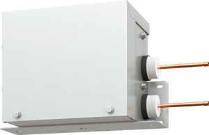
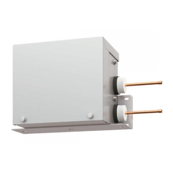
Внутренние блоки бытовой серии ПРЕМИУМ Инвертор MSZ-LN25~50VG, ДЕЛЮКС Инвертор MSZ-FH25~50VE, ДИЗАЙН Инвертор MSZ-EF22~50VE, СТАНДАРТ Инвертор MSZ-SF15/20VA и MSZ-SF25~50VE, а также напольные блоки MFZ-KJ25~50VE подключаются в мультизональную VRF-систему CITY MULTI с помощью специального М-контроллера PAC-LV11M-J. М-контроллер представляет собой металлический корпус, в котором смонтированы электронный ТРВ и электронный печатный узел для преобразования команд из сети M-NET в протокол управления бытовыми системами «A-control».
 PAC-LV11M-J (0,8 МБ, 2 стр.)
| Наименование | PAC-LV11M-J |
|---|---|
| Количество портов | 1 |
| Совместимые внутренние блоки | MSZ-LN25/35VG (кроме PUMY-P),
MSZ-LN50VG (кроме PUMY-(S)P), MSZ-FH25~50VE, MSZ-EF22~50VE, MSZ-SF15/20VA, MSZ-SF25~50VE, MFZ-KJ25~50VE (кроме PUMY-SP) |
| Совместимые наружные блоки | PUMY-(S)P VKM/YKM, PUCY-(E)P Y(S)KA,
PUHY-(E)P Y(S)NW-A, PUHY-HP YHM-A, PQHY-P YLM-A PURY-P Y(S)NW-A, PQRY-P YLM-A |
| Габаритные размеры (В×Ш×Д) | 183 мм х 355 мм х 142 мм |
| Вес прибора | 3,5 кг |
| Фреонопровод (жидкость) | 6,35 мм (1/4), пайка |
| Фреонопровод (газ) | нет |
| Электропитание | 1 фаза, 220 В, 50 Гц |
| Подключение дренажного трубопровода | не требуется |
| Совместимые пульты управления | Беспроводные пульты управления |
| Сигнальные линии | M-NET (CITY MULTI) и «new A-control» (RAC) |
| Завод (страна) | MITSUBISHI ELECTRIC CORPORATION AIR-CONDITIONING & REFRIGERATION SYSTEMS WORKS (Япония) |
Подбор оборудования Митсубиши
AIR CONDITIONING SYSTEMS
CONNECTION KIT
INSTALLATION MANUAL
For safe and correct use, please read this installation manual thoroughly before installing the indoor unit.
GB
PAC-LV11M-J
Contents
1. Safety precautions ........................................................................ 2
1.1. Before installation and electric work .............................. 2
1.2. Precautions for devices that use R410A refrigerant ...... 2
1.3. Before getting installed .................................................. 3
1.4. Before getting installed (moved) - electrical work .......... 3
1.5. Before starting the test run............................................. 3
2. Overview of units........................................................................... 4
2.1. System outline ............................................................... 4
2.2. Unit construction ............................................................ 4
2.3. Installation...................................................................... 5
3.
4.
5.
6.
7.
2.4. Dip switch setting..........................................................18
Specifications...............................................................................18
Outlines and dimensions..............................................................19
Wiring diagram.............................................................................20
Refrigerant system diagram.........................................................21
Troubleshooting ...........................................................................22
7.1. Test run.........................................................................22
7.2. Check methods.............................................................23
7.3. Dip switch setting (Factory setting)...............................26
1. Safety precautions
1.1. Before installation and electric work
GB
Before installing the unit, make sure you read all the “Safety precautions”.
The “Safety precautions” provide very important points regarding
safety. Make sure you follow them.
•
•
Symbols used in the text
Warning:
Describes precautions that should be observed to prevent danger of injury
or death to the user.
•
Caution:
Describes precautions that should be observed to prevent damage to the
unit.
•
Symbols used in the illustrations
: Indicates an action that must be avoided.
•
: Indicates that important instructions must be followed.
: Indicates a part which must be grounded.
: Indicates that caution should be taken with rotating parts. (This symbol is
displayed on the main unit label.) <Color: yellow>
•
•
: Beware of electric shock (This symbol is displayed on the main unit label.)
<Color: yellow>
1.2. Precautions for devices that use
R410A refrigerant
Warning:
Carefully read the labels affixed to the main unit.
Warning:
•
•
•
•
•
•
•
•
•
•
•
When installing and moving the unit to another site, do not charge the it
with a refrigerant different from the refrigerant specified on the unit.
- If a different refrigerant or air is mixed with the original refrigerant, the refrigerant cycle may malfunction and the unit may be damaged.
If the unit is installed in a small room, measures must be taken to prevent the refrigerant concentration from exceeding the safety limit even
if the refrigerant should leak.
- Consult the dealer regarding the appropriate measures to prevent the safety
limit from being exceeded. Should the refrigerant leak and cause the safety
limit to be exceeded, hazards due to lack of oxygen in the room could result.
When moving and reinstalling the unit, consult the dealer or an authorized technician.
- If the air conditioner is installed improperly, water leakage, electric shock, or
fire may result.
After completing installation work, make sure that refrigerant gas is not
leaking.
- If the refrigerant gas leaks and is exposed to a fan heater, stove, oven, or
other heat source, it may generate noxious gases.
Do not reconstruct or change the settings of the protection devices.
- If the pressure switch, thermal switch, or other protection device is shorted
and operated forcibly, or parts other than those specified by Mitsubishi Electric are used, fire or explosion may result.
To dispose of this product, consult your dealer.
Do not use a leak detection additive.
Ask the dealer or an authorized technician to install the connection kit.
- Improper installation by the user may result in water leakage, electric shock,
or fire.
Install the unit at a place that can withstand its weight.
- Inadequate strength may cause the unit to fall down, resulting in injuries.
Use the specified cables for wiring. Make the connections securely so
that the outside force of the cable is not applied to the terminals.
- Inadequate connection and fastening may generate heat and cause a fire.
Prepare for typhoons and other strong winds and earthquakes and
install the unit at the specified place.
- Improper installation may cause the unit to topple and result in injury.
Always use an air cleaner, humidifier, electric heater, and other accessories specified by Mitsubishi Electric.
- Ask an authorized technician to install the accessories. Improper installation
by the user may result in water leakage, electric shock, or fire.
Never repair the unit. If the unit must be repaired, consult the dealer.
- If the unit is repaired improperly, water leakage, electric shock, or fire may
result.
When handling this product, always wear protective equipment.
EG: Gloves, full arm protection namely boiler suit, and safety glasses.
- Improper handling may result in injury.
If refrigerant gas leaks during installation work, ventilate the room.
- If the refrigerant gas comes into contact with a flame, poisonous gases will
be released.
Install the unit according to this Installation Manual.
- If the unit is installed improperly, water leakage, electric shock, or fire may
result.
Have all electric work done by a licensed electrician according to “Electric Facility Engineering Standard” and “Interior Wire Regulations” and
the instructions given in this manual and always use a special circuit.
- If the power source capacity is inadequate or electric work is performed
improperly, electric shock and fire may result.
Keep the electric parts away from water (washing water etc.).
- It might result in electric shock, catching fire or smoke.
2
Caution:
•
•
•
•
•
•
•
•
•
Do not use the existing refrigerant piping.
- The old refrigerant and refrigerator oil in the existing piping contains a large amount
of chlorine which may cause the refrigerator oil of the new unit to deteriorate.
Use refrigerant piping made of C1220 (Cu-DHP) phosphorus deoxidized
copper as specified in the JIS H3300 “Copper and copper alloy seamless pipes and tubes”. In addition, be sure that the inner and outer surfaces of the pipes are clean and free of hazardous sulphur, oxides, dust/
dirt, shaving particles, oils, moisture, or any other contaminant.
- Contaminants on the inside of the refrigerant piping may cause the refrigerant residual oil to deteriorate.
Store the piping to be used during installation indoors and keep both
ends of the piping sealed until just before brazing. (Store elbows and
other joints in a plastic bag.)
- If dust, dirt, or water enters the refrigerant cycle, deterioration of the oil and
compressor trouble may result.
Use liquid refrigerant to fill the system.
- If gas refrigerant is used to seal the system, the composition of the refrigerant in the cylinder will change and performance may drop.
Do not use a refrigerant other than R410A.
- If another refrigerant (R22, etc.) is used, the chlorine in the refrigerant may
cause the refrigerator oil to deteriorate.
Use a vacuum pump with a reverse flow check valve.
- The vacuum pump oil may flow back into the refrigerant cycle and cause the
refrigerator oil to deteriorate.
Do not use the following tools that are used with conventional refrigerants.
(Gauge manifold, charge hose, gas leak detector, reverse flow check
valve, refrigerant charge base, vacuum gauge, refrigerant recovery
equipment)
- If the conventional refrigerant and refrigerator oil are mixed in the R410A, the
refrigerant may deteriorated.
- If water is mixed in the R410A, the refrigerator oil may deteriorate.
- Since R410A does not contain any chlorine, gas leak detectors for conventional refrigerants will not react to it.
Do not use a charging cylinder.
- Using a charging cylinder may cause the refrigerant to deteriorate.
Be especially careful when managing the tools.
•
1.3. Before getting installed
Caution:
•
•
•
•
•
•
Do not install the unit where combustible gas may leak.
- If the gas leaks and accumulates around the unit, an explosion may result.
Do not use the connection kit where food, pets, plants, precision instruments, or artwork are kept.
- The quality of the food, etc. may deteriorate.
Do not use the unit in special environments.
- Oil, steam, sulfuric smoke, etc. can significantly reduce the performance of
the unit or damage its parts.
When installing the unit in a hospital, communication station, or similar
place, provide sufficient protection against noise.
- The inverter equipment, private power generator, high-frequency medical
equipment, or radio communication equipment may cause the air conditioner to operate erroneously, or fail to operate. On the other hand, the unit
may affect such equipment by creating noise that disturbs medical treatment
or image broadcasting.
Do not install the unit on a structure that may cause leakage.
- When the room humidity exceeds 80% or when the drain pipe is clogged,
condensation may drip from the indoor unit. Perform collective drainage
work together with the outdoor unit, as required.
The unit should be installed the ceiling over than 2.5 m from floor.
•
•
•
•
•
Do not touch the refrigerant pipes during and immediately after operation.
- During and immediately after operation, the refrigerant pipes are may be hot
and may be cold, depending on the condition of the refrigerant flowing
through the refrigerant piping, compressor, and other refrigerant cycle parts.
Your hands may suffer burns or frostbite if you touch the refrigerant pipes.
Do not operate the unit with the panels and guards removed.
- Rotating, hot, or high-voltage parts can cause injuries.
Do not turn off the power immediately after stopping operation.
- Always wait at least five minutes before turning off the power. Otherwise,
water leakage and trouble may occur.
If the supply cord is damaged, it must be replaced by the manufacturer,
its service agent or similarly qualified persons in order to avoid a hazard.
This appliance is not intended for use by persons (including children)
with reduced physical, sensory or mental capabilities, or lack of experience and knowledge, unless they have been given supervision or
instruction concerning use of the appliance by a person responsible for
their safety.
Children should be supervised to ensure that they do not play with the
appliance.
GB
- If dust, dirt, or water gets in the refrigerant cycle, the refrigerant may deteriorate.
1.4. Before getting installed (moved) electrical work
Caution:
•
•
•
•
•
•
•
•
•
•
Ground the unit.
- Do not connect the ground wire to gas or water pipes, lightning rods, or telephone ground lines. Improper grounding may result in electric shock.
Install the power cable so that tension is not applied to the cable.
- Tension may cause the cable to break and generate heat and cause a fire.
Install a leak circuit breaker, as required.
- If a leak circuit breaker is not installed, electric shock may result.
Use power line cables of sufficient current carrying capacity and rating.
- Cables that are too small may leak, generate heat, and cause a fire.
Use only a circuit breaker and fuse of the specified capacity.
- A fuse or circuit breaker of a larger capacity or a steel or copper wire may
result in a general unit failure or fire.
Do not wash the unit.
- Washing them may cause an electric shock.
Be careful that the installation base is not damaged by long use.
- If the damage is left uncorrected, the unit may fall and cause personal injury
or property damage.
Install the drain piping according to this Installation Manual to ensure
proper drainage. Wrap thermal insulation around the pipes to prevent
condensation.
- Improper drain piping may cause water leakage and damage to furniture and
other possessions.
Be very careful about product transportation.
- Some products use PP bands for packaging. Do not use any PP bands for a
means of transportation. It is dangerous.
Safely dispose of the packing materials.
- Packing materials, such as nails and other metal or wooden parts, may
cause stabs or other injuries.
- Tear apart and throw away plastic packaging bags so that children will not
play with them. If children play with a plastic bag which was not torn apart,
they face the risk of suffocation.
1.5. Before starting the test run
Caution:
•
•
Turn on the power at least 12 hours before starting operation.
- Starting operation immediately after turning on the main power switch can
result in severe damage to internal parts. Keep the power switch turned on
during the operational season.
Do not touch the switches with wet fingers.
- Touching a switch with wet fingers can cause electric shock.
3
2. Overview of units
2.1. System outline
2.1.1. System example
Connection kit
Connection kit
Connection kit
Connection kit
GB
Outdoor unit
2.2. Unit construction
Outdoor unit
Indoor unit that
can be
connected
Capacity
Number of units
Total system wide
capacity
Refer to manuals of the outdoor unit.
+
Branching Pipe
Connection kit
Wall mounted
* For connectable indoor unit
models, consult your dealer.
4
2.3. Installation
2.3.1. Installing the connection kit
Parts to procure locally
• Suspension bolts or anchor bolts : W3/8 (M10)
• Nut : W3/8 (M10)
• Washer : W3/8 (M10)
Wooden structures
• Use tie beams (single storied houses) or second floor beams (two
story houses) as reinforcing members.
• Wooden beams for suspending air conditioners must be sturdy and
their sides must be at least 6 cm long if the beams are separated by
not more than 90 cm. The size of the suspension bolts should be
M10 (W3/8). (The bolts are not supplied with the unit.)
A Ceiling
B Rafter
C Beam
D Roof beam
B* Suspension bolt pitch
Ferro-concrete structures
Secure the suspension bolts using the method shown, or use
steel or wooden hangers, etc. to install the suspension bolts.
E Use inserts rated at 100-150 kg each (procure locally)
F Suspension bolts M10 (W3/8) (procure locally)
G Steel reinforcing rod
MIN.30
(When unit is hung
and nuts tightened)
(2) Install the connection kit.
(Unit: mm)
Suspension bolt M10
(ޓprocure locally)
Nut (procure locally)
Washer (procure locally)
Washer (procure locally)
Nuts (procure locally)
Unit
Installing the unit on a wall
(1) Install the anchor nuts.
(2) Install the connection kit.
Do not install the refrigerant pipes on top of the
unit when installing the unit on a wall, otherwise
condensation can enter the electrical devices,
which can cause an electric shock or a fire.
5
GB
Installing the unit in a ceiling
(1) Install the suspension bolts.
Connect the Connection Kit to the liquid pipe and install it inside the ceiling or on a wall (Do not install in an outdoor location. It may
cause a breakdown). Make sure to install the access door on the ceiling.
Installation location
• The installation patterns below are available. Select the installation pattern according to the preferred installation method. The
distance between indoor unit and Connection Kit is within 15 m. (Pipe:15 m, Cable:2.5 m)
• Install the connection kit at a height of 2.5 m or above from the floor, where it is not easily accessible for the users.
Installation pattern A (Using suspension bolt ; recommended pattern)
Set the Connection Kit mounting plate as shown below.
The mounting plate can also be fixed to suspension bolts before it is fixed to the Connection Kit.
(Unit: mm)
Mounting plate
MIN.30
GB
Install the two screws (5 × 10)
240
Suspension bolt pitch
Suspension bolt M10
181
Ceiling
Wall
MIN.100
MIN.500
SERVICE SPACE
MIN.200
182
Installation pattern B (Installing the unit on a wall.)
(Unit: mm)
Set the Connection Kit mounting plate as shown below.
Install the two screws (5 × 10)
MIN.30
Mounting plate
250
ANCHOR NUT PITCH
Install the four screws (4×50 procure
locally) in oval holes.
Anchor nuts
(procure locally)
110
Ceiling
6
MIN.100
4-Oval holes
Oval hole dimension
5
62
ANCHOR NUT PITCH
181
Wall
(R
10
)
MIN.200
Wall
MIN.500
SERVICE SPACE
MIN.50
Installation pattern C (Installing the unit on a wall.)
Set the Connection Kit mounting plate as shown below.
(Unit: mm)
Install the two screws (5 × 10)
500
SERVICE SPACE
Mounting plate
Ceiling
250
ANCHOR NUT PITCH
Anchor nuts
(procure locally)
183
62
ANCHOR NUT PITCH
69
GB
500
SERVICE SPACE
Wall
4-Oval holes
Wall
MIN.50
MIN.200
MIN.100
Install the four screws (4×50 procure
locally) in oval holes.
(Unit: mm)
Installation pattern D (Installing the unit on a wall.)
Set the Connection Kit mounting plate as shown below.
Install the two screws (5 × 10)
Mounting plate
Anchor nuts
(procure locally)
250
ANCHOR NUT PITCH
MIN.200
Ceiling
MIN.30
183
MIN.50
4-Oval holes
Wall
Wall
MIN.30
62
ANCHOR NUT PITCH
69
500
SERVICE SPACE
Install the four screws (4×50 procure
locally) in oval holes.
7
2.3.2. Installing the refrigerant piping
Check the Connection Kit accessories and parts
1Pipe cover × 2
2Thermistor holder - ø9.52 × 1
3Thermistor holder - ø12.7 × 1
Connect Connection Kit to the liquid pipe.
When brazing the refrigerant pipes, be sure to braze, after covering a wet cloth to the insulation pipes of the units in order to prevent
it from burning and shrinking by heat.
Brazing
To indoor unit
GB
To outdoor unit
Refrigerant pipe (procure locally)
Connection kit
Press the pipe cover 1 on the liquid piping against the Connection Kit and wrap it to hold it in place.
Fasten the supplied bands 20 mm from each of the pipe covers 1.
Band (procure locally)
1Pipe cover
20
Connection kit
20
(120)
Wrap the pipe cover 1 with tape.
Tape (procure locally)
8
Refrigerant pipe
(procure locally)
2.3.3. Installing the thermistors
Be sure to install the thermistors (gas) supplied with the unit as shown in the illustration.
• If the thermistors are not installed, the unit will not operate. If the thermistors are installed incorrectly, the unit will not operate
properly.
Take precaution so that condensation does contact the thermistor leads or enters the electrical devices.
Before installing thermal insulation to the frame connecting points of the indoor unit, be sure to install the thermistors
according to the procedures given on this page.
* Refer to section 8.4 "Wiring (mm)" for the location of CN44.
MAX. 15000
Connection kit
Brazed point
Gas: CN44
MAX. 2000
GB
1500
Thermistor installation order
(1) Securely fasten the thermistor (gas) supplied with the unit using the thermistor holders (2, 3) at the fastening points of indoor
unit refrigerant pipes.
• Set thermistor-G (gas) in thermistor holders 2 or 3, and then fasten the refrigerant pipes.
Select thremistor holders that match the size
of the refrigerant piping.
Indoor unit capacity
15-40
50
pipe size (mm)
Gas
Liquid
ø9.52
ø6.35
ø12.7
ø6.35
(procure locally)
MAX. 1500 mm
Gas
2
•
•
•
•
3
Caution:
To prevent condensation from dripping on the thermistor fasteners, wrap them with sufficient thermal insulation.
Install the thermistor so that the piping is on top (as shown in above illustration).
Take out the thermistor lead from above the piping.
Install the thermistor indoors.
• Route the following lead, line, and cable pairs so that they do not come into contact with each other.
- Thermistor lead and indoor unit-connection kit transmission line
- Thermistor lead and power supply cable
- Transmission line and power supply cable
9
(2) Insulate the thermistor with the supplied thermal insulation (procure locally).
Thermal insulation (procure locally)
(3) Cut a 100 mm slit on the top portion of the extension piping pipe cover, and then cover the thermistors with the pipe cover.
GB
Pipe cover (procure locally)
(4) Wrap the thermal insulation covering the thermistor with tape.
Caution:
Be sure to take out the thermistor lead from above.
Tape (procure locally)
Thermistor lead
(procure locally)
Tape (procure locally)
(5) Cover the thermistor with the thermal insulation.
Thermal insulation (procure locally)
Bundle up the excess thermistor lead.
•
•
•
•
Caution:
Do not make the thermistor lead taut.
Do not add extensions to the thermistor lead.
Do not cut the excess thermistor lead.
Make sure that the bundle of thermistor lead does not interfere with any other wiring.
10
2.3.4. Electrical work
2.3.4.1. Caution
Connection kit
Outdoor unit
(51)
(01)
TB3
M1M2 S
TB5
TB
M1M2 S S1S2S3
Connection kit
(02)
L1
TB5
TB
M1M2 S S1S2S3
ℓ1
ℓ2
L2
L3
S1S2S3
TB
S1S2S3
TB
Indoor unit
Indoor unit
Connection kit
(03 )
TB5
M1 M2 S
TB
S1S2S3
ℓ3
(7) Before turning the indoor unit and the connection kit on,
be sure to set the switches.
(8) To turn the power on, turn on the indoor unit, connection
kit, then the outdoor unit, in that order.
GB
(1) Follow local regulations and ordinances for technical
standards related to electrical equipment, wiring, and
specifications of each electric power company.
(2) Wiring for control (hereinafter referred to as transmission line)
must be situated at least 5 cm from the power source wiring
so that it is not influenced by electrical noise. (Do not insert
transmission line and power source wire in the same conduit.)
(3) Be sure to provide designated grounded work to outdoor unit.
(4) Never connect the main power source to the terminal block of
a transmission line. If connected, electrical parts will be burnt
out.
(5) Use a 2-core shield cable for connecting a transmission line to
TB5 of the connection kit. If transmission of different systems
are wired with the same multiplecore cable, which can result
in poor transmission and receipt and can cause incorrect
operation.
(6) The system will not operate if connected improperly.
TB2 : Terminal block for power supply
TB : Terminal block for transmission line to indoor unit
TB5 : Terminal block for transmission line to outdoor unit
S1S2S3
TB
Indoor unit
(9) For identification purposes, list the indoor unit model names in
the nameplate on the control box of the connection kit.
(10) Provide grounding for the indoor unit and the connection kit
separately.
(11) Secure the connection kit wires in place with the Cable bands
(Refer to Section 2.3.4.4.) to protect against external forces.
(12) Secure the connection kit wires in place with the Bands (Refer
to Section 2.3.4.4.) to prevent fingers from coming in contact
with the inside of the connection kit from the wire outlet.
2.3.4.2. Connecting the connection kit, indoor and outdoor unit transmission cables
• Connect the outdoor unit (TB3) to the connection kit (TB5). (Non-polarized 2-wire) The "S" terminal on the connection kit (TB5) is
a shielding wire connection. For connecting cable specifications, refer to the outdoor unit installation manual.
• Connect the indoor unit (TB) to the connection kit (TB). For connecting cable specifications, refer to the indoor unit installation
manual.
Permissible Length
1 "Indoor unit - connection kit"
Maximum transmission cable length : ℓ1 and ℓ2, ℓ3 ≤ 10 m (2-Core 1.0 mm2)
2 "Outdoor unit - connection kit" + "connection kit - connection kit"
Maximum transmission cable length : (L1 + L2) or (L 1 + L 3) or (L2 + L 3) ≤ 200 m
2.3.4.3. Wiring of main power supply and equipment capacity
Connection kit
Thickness of wire for main power supply and on/off capacities
Model
Connection kit
Minimum wire thickness (mm2)
Main cable
Branch
Ground
1.5
1.5
1.5
Breaker for wiring (NFB)
Breaker for current leakage
15 A
15 A
11
1. Use separate power supplies for the outdoor unit and connection kit.
2. Consider the ambient conditions (ambient temperature, direct sunlight, rain, etc.) when wiring and making connections.
3. The wire size is the minimum value for metal conduit wiring. The power cord size must be 1 rank thinker in consideration of voltage
drops.
Make sure that the power supply voltage does not drop more than 10%.
4. Select non-fuse breaker (NFB) or earth leakage breaker (NV).
(A means for the disconnection of the supply with an isolation switch, or similar device, in all active conductors shall be
incorporated in the fixed wiring.)
5. Power supply codes of appliance must not be lighter than design 60245 IEC 53 or 60227 IEC 53.
6. A switch with at least a 3 mm contact separation in each pole must be provided by the air conditioner installation.
Power cable size : more than 1.5 mm2.
GB
Warning:
• Be sure to use the specified wires for connection so that no external force is imparted to the terminal connections.
If the wires are not securely connected, a fire can occur.
• Be sure to use the appropriate type of overcurrent protection switch. Note that generated overcurrent may include some
amount of direct current.
Caution:
• Some installation sites may require a ground-fault interrupter. If a ground-fault interrupter is not installed, an electric
shock can occur.
• Use only a circuit breaker and fuse of the specified capacity. Using a fuse and copper wire with excessive capacity can
cause a malfunction or a fire.
• The temperature set at the last operation takes priority by operating the system controller, MA/ME remote controller, or
local remote controller.
When connected to a CITY MULTI indoor unit in a system
M-NET system remote controllers cannot be used to operate the indoor unit that is connected to the connection kit.
<Restrictions>
1. The indoor unit to which the connection kit is connected cannot be in the same group to which a City Multi indoor unit belongs.
2. A group operation using M-NET between the indoor unit to which the connection kit is connected and other indoor unit cannot be
performed properly if an M-NET Interface (MAC-333IF or MAC-399IF) is connected to the indoor unit using IT terminal.
3. If the connection kit is used, a group operation can be performed via the system controller or ME remote controller only. (A group
operation cannot be performed via the wireless remote controller or MA remote controller.)
12
Examples of UNACCEPTABLE unit configurations
(1) Grouping with CITY MULTI indoor unit
E
A
The connection kit cannot be in the
same group to which a CITY MULTI
indoor unit belongs because their
signal information differs.
Address: 51
B
E
Address: 01
Address: 02
A
A
Address: 51
Address: 52
Group
A-control
B
B
Address: 01
Address: 02
F
C
A-control
A-control
C
C
IT terminal
D
GB
G
(2) Connecting an MA & Contact Termianl Interface using
IT terminal
IT terminal
D
D
This unit configuration is not
acceptable because signal information
for the indoor unit to which the
connection kit is connected and the
MA & Contact Terminal Interface
A Outdoor unit
B Connection kit
C Indoor unit
D Remote controller
E CITY MULTI indoor unit
F Remote controller (ME)
G M-NET transmission cable
A Outdoor unit
B Connection kit
C Indoor unit
D M-NET Interface
E System controller
(3)-1 When using wireless remote controller
(3)-2 When using MA remote controller
A
E
Address: 51
This unit configuration is not
acceptable because only one indoor
unit can be operated properly from
the wireless remote controller
(referred to as WR in the figure).
B
B
Address: 01
Address: 02
Group
This unit configuration is not
acceptable because signal
information for the City Multi indoor
unit and MAC-397IF differs.
A
G
Address: 51
B
F
Address: 01
Address: 02
A-control
C
C
C
IT communication
D
D
E
H
A Outdoor unit
B Connection kit
C Indoor unit
D Remote controller
E M-NET transmission cable
A Outdoor unit
B Connection kit
C Indoor unit
D MA & Contact Terminal Interface
E Remote controller (MA)
F CITY MULTI indoor unit
G M-NET transmission cable
H MA transmission cable
13
Examples of ACCEPTABLE unit configurations
(1) Connecting with CITY MULTI outdoor unit
A: PURY
A: PUHY
A
F
A
E
Address: 51
Address: 51
TB3
TB3
B
B
Address: 01
Address: 01
TB5
TB5
TB
TB
A-control
GB
D
A-control
C
C
Address: 52
TB02
E
D
A Outdoor unit
B Connection kit
C Indoor unit
D Remote controller
E M-NET transmission cable
A Outdoor unit
B Connection kit
C Indoor unit
D BC controller
E Remote controller
F M-NET transmission cable
(2) Connecting MA remote controller
(3) Connecting ME remote controller
A
F
Address: 51
A
TB3
E
Address: 51
TB3
B
Address: 01
TB5
B
TB
Address: 01
A-control
C
TB
TB5
A-control
IT communication
C
D
D
MA communication line
E
A Outdoor unit
B Connection kit
C Indoor unit
D MAC 397IF
E Remote controller (MA)
F M-NET transmission cable
14
A Outdoor unit
B Connection kit
C Indoor unit
D Remote controller (ME)
E M-NET transmission cable
(4) Grouping with multi-connection kit and RAC indoor units
F
E
A
TB7
TB7
E
Address: 51
A
A
E
Address: 51
TB3
Address: 51
F
E
TB3
TB3
B
B
B
Address: 01
Address: 02
B
B
Address: 01
Address: 02
B
Address: 01
TB5
TB
TB5
TB
TB5
TB
A-control
TB
C
A-control
A-control
C
TB5
Address: 02
C
TB5
A-control
TB5
TB
A-control
C
C
Group
Group
TB
A-control
C
GB
D
Group
D
D
A Outdoor unit
B Connection kit
C Indoor unit
D System controller
E M-NET transmission cable
A Outdoor unit
B Connection kit
C Indoor unit
D Remote controller (ME)
E M-NET transmission cable
A Outdoor unit
B Connection kit
C Indoor unit
D Remote controller (ME)
E System controller
F M-NET transmission cable
15
2.3.4.4. Wiring
Check the Connection Kit accessories and parts
1Cable band × 2
2Thermistor
(1) Remove the electrical cover.
(2) Install the two cable bands 1.
118
Electrical cover
1Cable band
Electrical wire inlet (Power supply, To indoor unit)
57
AT-adapter board
Bands
68
Electrical wire inlet (To outdoor unit, From gas thermistor)
GB
Terminal block
1Cable band
Screws
Controller board
(3) Insert the wiring and thermistor 2 into the unit, and then fasten them with the bands on the inside of the unit.
(4) Connect each wire to the terminal block securely.
(5) Connect thermistor 2 to CN44 of the controller board.
(6) Fix the cable bands 1 tightly so that the cables outside the unit will not be pulled out.
Ground terminal
Terminal block: TB2
(power supply)
-/N 220-240 V/220 V
50/60Hz
Power supply cable
Terminal block: TB
(to indoor unit)
Controller board
CN44
SW3
Indoor unit cable
SW2
1Cable band
SW11
SW1
SW12
SW14
SW4
Bands
1Cable band
Outdoor unit cable
SWC
2Thermistor cable
Terminal block: TB5
(to outdoor unit)
remote controller
SW5
SWA
(7) After installing the unit, install the electric cover.
16
2.3.5. Refrigerant piping
Indoor unit connection example
• Connect one connection kit per indoor unit.
• Connect the connection kit the liquid pipe.
• The thermistor-G (gas) is installed close to the connecting point of the extension piping (gas) for the indoor unit.
Connection kit
MAX. 15 m
(Brazed)
Indoor unit capacity
Liquid pipe size (mm)
15-50
ø6.35 × 0.8
* Connection kit
GB
Piping connection size
ø6.35 × 0.8
Additional refrigerant quantity
• If necessary, add additional refrigerant to the unit by following the calculation method given in the outdoor unit manual.
• When calculating the refrigerant quantity, be sure to include the connection kit-to-indoor unit liquid pipe length.
• The amount of refrigerant required by the indoor units must be charged to the system. Refer to the manual that came with the
outdoor unit for details.
2.3.6. Error code
The table below summarizes the error codes for the indoor and outdoor units that are connected to the connection kit. Refer to the
relevant Service Handbook for other error codes.
Error code
0404
4124
6840
6841
6842
6843
Indoor unit error code
(reference)
Fb, FC
PE
E6, E8
E9
E7, E9
E6, E8
Error type
Indoor unit EEPROM abnormality
Electric system not operate due to damper abnormality
A control communication reception error
A control communication synchronism not recover
A control communication transmission/reception hardware trouble
A control communication start bit detection error
17
2.4. Dip switch setting
(1) SW2
Set the dip switches in the connection kit as follows to configure the capacity settings for the connected indoor unit.
Model P15, P20
Capacity (model) code
3
SW2
setting
P22
4
123456
ON
OFF
P25
5
123456
ON
OFF
P32, P35 P40, P42
6
8
123456
123456
ON
OFF
ON
OFF
P50
9
123456
ON
OFF
P63
13
123456
123456
ON
OFF
P71
14
ON
OFF
P80
16
123456
123456
ON
OFF
P100
20
ON
OFF
P125
25
123456
ON
OFF
P140
28
123456
ON
OFF
P200
40
123456
123456
123456
ON
OFF
P250
50
ON
OFF
ON
OFF
Note. The setting timing for SW2 is before power is turned on.
(2) SW4
Set the dip switches in the connection kit as follows.
GB
SW4
setting
(3) Address switch
Actual indoor unit address setting varies in different systems. Refer to the installation manual for the outdoor unit for details on
how to make the address setting.
Each address is set with a combination of the settings for the 10's digit and 1's digit.
(Example)
When setting the address to "3", set the 1's digit to 3, and the 10's digit to 0.
When setting the address to "25", set the 1's digit to 5, and the 10's digit to 2.
(4) BRANCH No. setting (Only PURY)
Setting method
• Assign the smallest address to the main unit in the group.
• In a system with a sub BC controller, make the settings for the indoor units in the following order.
(i) Indoor unit to be connected to the main BC controller
(ii) Indoor unit to be connected to sub BC controller 1
(iii) Indoor unit to be connected to sub BC controller 2
Make the settings for the indoor units in the way that the formula "(i) < (ii) < (iii)" is true.
Note
• In case of connecting with BC controller, BRANCH No. setting is required.
(5) Other
When the unit is used in a high-temperature and humidity atmosphere, change the dip switch settings of the outdoor unit as follows.
Model
PUHY/PURY
-*H* series
-*J* series
PUHY/PURY
-*K* series or later
Dip switch setting
SW4
SW4-1: ON
SW4
1-10
(0: OFF, 1: ON)
1000000111
(897)
3. Specifications
SPECIFICATIONS OF OPTIONAL PARTS
MODEL
PAC-LV11M-J
Power source
Single/220-240 V/50/60 Hz
Connectable number of indoor units
1
External finish
Hot-dip zinc-coated steel sheet (No external finish)
External dimension H×W×D
mm
183 × 355 × 142
Net weight
kg
3.5
Liquid pipe
mm
6.35 Brazed
Refrigerant piping
diameter
Gas pipe
mm
Wiring
To Outdoor unit
2-core shield cable
18
4-10×5 oblong holes
(For wall surface installation)
㧨To outdoor unit㧪
Wiring to terminal block: TB5
㧨To gas pipe㧪
Wiring from gas thermistor
Note 3
Screw bolt (M5×10)
㧨POWER SUPPLY㧪
Wiring to terminal block: TB2
1-phase 220-240V 50, 60Hz
㧨To indoor unit㧪
Wiring to terminal block: TB
24
Installation plate
2-ø12 holes
(For suspension bolt)
68
58
142
183
240
15
280
250
213
250
20
280
15
100
4-10×5 oblong holes
(For plane surface installation)
355
109
GB
Connection pipe
of outdoor unit
ø6.35㧨Brazed㧪
Connection pipe
of indoor unit
ø6.35㧨Brazed㧪
110
㧨Accessories㧪
ޓޓInstallation plate㨯㨯㨯㨯㨯㨯㨯㨯㨯㨯㨯㨯㨯㨯㨯㨯㨯㨯㨯㨯㨯㨯㨯㨯1pc.
ޓGas thermistor㨯㨯㨯㨯㨯㨯㨯㨯㨯㨯㨯㨯㨯㨯㨯㨯㨯㨯㨯㨯㨯㨯㨯㨯㨯㨯1pc.
ޓThermistor holder (ø9.52)㨯㨯㨯㨯㨯㨯㨯㨯㨯㨯㨯㨯1pc.
ޓThermistor holder (ø12.7)㨯㨯㨯㨯㨯㨯㨯㨯㨯㨯㨯㨯1pc.
ޓScrew bolt (M5×10)㨯㨯㨯㨯㨯㨯㨯㨯㨯㨯㨯㨯㨯㨯㨯㨯㨯㨯㨯㨯2pc.
ޓPipe cover㨯㨯㨯㨯㨯㨯㨯㨯㨯㨯㨯㨯㨯㨯㨯㨯㨯㨯㨯㨯㨯㨯㨯㨯㨯㨯㨯㨯㨯㨯㨯2pc.
ޓCable band㨯㨯㨯㨯㨯㨯㨯㨯㨯㨯㨯㨯㨯㨯㨯㨯㨯㨯㨯㨯㨯㨯㨯㨯㨯㨯㨯㨯㨯㨯2pc.
65
34
62
69
62
11
Note 1. Please attach a gas thermistor to the gas pipe of a spot.
2. When this is shipped from the factory, the installation
plate is not attached to the mainbody.
3. When you install the unit on a wall, please attach the
installation plate referring to the left figure. (M5×10)
4. When you use the suspension bolt, please attach the
installation plate inside out.
5. Suspension bolt (ø10), washer (M10), and nut (M10)
prepare in the field.
4. Outlines and dimensions
19
20
TO INDOOR UNIT
FUSE
C.B.
P.B.
A.B.
TB2
TB
TB5
F001
ZNR001
NR
SA
TH23
LED1
SYMBOL
Power source terminal block
Transmission terminal block
Transmission terminal block
Fuse AC250V 6.3A
Varistor
Varistor
Surge Absorber
Thermistor (piping temp.detection/gas pipe)
LED (Power supply)
Controller board
Power supply board
AT-adapter board
NAME
SYMBOL EXPLANATION
TO OUTDOOR UNIT
REMOTE CONTROLLER
POWER SUPPLY
ޓAC220-240V
ޓ50, 60Hz
BREAKER
M1
M2
S
S3
S1
S2
L
N
SW1(C.B.)
SW2(C.B.)
SW3(C.B.)
SW4(C.B.)
SW5(C.B.)
SW11(C.B.)
SW12(C.B.)
SW14(C.B.)
SWA(C.B.)
SWC(C.B.)
LEV
SYMBOL
TB5
TB
TB2
A.B.
NAME
2
1
CN570
(Red)
CN450
5
4
3
2
1
3
2
1
ZNR001
CN351
(Blue)
U
123
Switch (for mode selection)
Switch (for capacity code)
Switch (for mode selection)
Switch (for model selection)
Switch (for mode selection)
Switch (1s digit address set)
Switch (10ths digit address set)
Switch (BRANCH No.)
Switch (for static pressure selection)
Switch (for static pressure selection)
Linear expansion valve
F001
CN001
2
1
CN105
(Red)
1
2
3
4
5
CN2M
(Blue)
1
2
5
4
3
2
1
NR
SW1
SW2
SW3
CN44
4
3
2
1
SW4
SW14
SW12
SW11
SWA
CN60
6
5
4
3
2
1
SW5
SWC
C.B.
(Heavy dotted line): Field wiring
:Terminal
NOTE: Symbols used in wiring diagram above are,
DC280-340V
Rectifier circuit
LED1
CNXB2
CN2S
U
SA
CNXC2
2
1
CNSK
(Red)
3
2
1
TAB1
P.B.
LEV
M
CITY MULTI CONNECTION KIT
GB
TH23
5. Wiring diagram
6. Refrigerant system diagram
(B)
(A)
(D)
(C)
(F)
(G)
(E)
(E)
GB
(H)
(A)
Gas pipe thermistor TH23
(B)
Gas pipe
(C)
Liquid pipe
(D)
Brazed connections
(E)
Strainer (#100 mesh)
(F)
Linear expansion valve
(G)
Indoor unit
(H)
Connection kit
21
7. Troubleshooting
7.1. Test run
Caution:
Before operating the unit, check that the wiring, piping, and thermistor are installed and that the switches have been set.
GB
Refer to the "Test run" section of the indoor units and outdoor unit installation manuals.
After installation of an indoor unit, connection kit, and outdoor unit, begin a test run to check water leaks in the connection kit.
Be sure to perform a test run in cooling mode for each indoor unit installed. Make sure that each indoor unit operates
properly following the installation manual supplied with the unit.
If a test run is performed on all indoor units at once, improper connection of the refrigerant pipes and the indoor and outdoor unit
connecting wires cannot be detected.
Caution:
• Always use the remote controller to operate the indoor unit.
• When using a connection kit, operation from the outdoor unit is not possible.
• The following symptoms are not malfunctions.
.
Symptom
Cause
The cooling (heating) operation cannot be operated
Indoor unit does not operate
even if set to cooling (heating ) when the cooling (heating) operation of another
indoor unit is operating.
operation
Indoor unit fan stops during
heating operation
The fan stops during defrosting operation.
Fan stops when the refrigerant collecting mode ** is
activated.
When this occurs, the vanes close.
Indoor unit LED display *
Stand by
(For Multi System)
Stand by
(For Multi System)
* See the operation manual of indoor units for details.
** This mode is activated for approximately 1 minute to help avoid an insufficient supply of refrigerant during heating operation when
refrigerant is stored in an indoor unit that has been turned off or thermo-off.
• A hissing noise can be heard immediately after the air conditioner is started or stopped. This is the sound of the refrigerant flowing
inside a connection kit. The problem is insignificant.
22
7.2. Check methods
1. Component and check points
(1) Thermistor
Gas pipe thermistor (TH23)
Disconnect the connector and measure the resistance between terminals with a tester.
(Ambient temperature 10°C - 30°C)
Normal
Abnormal
4.3kΩ - 9.6kΩ
Open or short
(Refer to the thermistor characteristic graph below.)
1) Thermistor characteristic graph
Low-temperature thermistor
Gas pipe thermistor (TH23)
Rt = 15 exp { 3480(
1
273+t
1 )}
273
GB
50
Thermistor R0 = 15 kΩ±3%
Multiplier of B = 3480 kΩ±2%
40
30
(B)
0°C 15kΩ
10°C 9.6kΩ
20°C 6.3kΩ
25°C 5.2kΩ
30°C 4.3kΩ
40°C 3.0kΩ
20
(A) Temperature
(°C)
(B) Resistance
(kΩ)
10
0
-20
-10
0
10
20
30
40
50
(A)
(2) Linear expansion valve
Disconnect the connector, and measure the resistance between terminals with a tester.
Refer to the next page for details.
Normal
(F)
(E)
(D)
M
(C)
(B)
LEV
(A)
CN60
1
2
3
4
5
6
1-5
White-Red
2-6
Yellow-Brown
Abnormal
3-5
Orange-Red
4-6
Blue-Brown
Open or short
200 kΩ±10%
(A)
Brown
(D)
Orange
(B)
Red
(E)
Yellow
(C)
Blue
(F)
White
23
1) Summary of linear expansion valve (LEV) operation
The LEV is operated by a stepping motor, which operates by receiving a pulse signal from the controller board.
The LEV position changes in response to the pulse signal.
Controller board and LEV connection
(G)
12VDC
(A)
6
(C)
(B)
5
(A)
(C)
4
(E)
(D)
3
(E)
2
(F)
1
(J)
4
M
6
5
2
1
3
GB
(F) (B) (D)
(H)
(A)
Brown
(F)
White
(B)
Red
(G)
Control board
(C)
Blue
(H)
Connection (CN60)
(D)
Orange
(I)
Drive circuit
(E)
Yellow
(J)
Linear expansion valve
Pulse signal output and valve operation
Phase
number
Output pulse
1
2
3
4
ø1
ON
OFF
OFF
ON
ø2
ON
ON
OFF
OFF
ø3
OFF
ON
ON
OFF
ø4
OFF
OFF
ON
ON
The output pulse changes in the following order:
When the valve closes 1 -> 2 -> 3 -> 4 -> 1
When the valve opens 4 -> 3 -> 2 -> 1 -> 4
When the valve position remains the same, all output signals will be OFF.
If any output signal is missing or if the signal remains ON, the motor vibrates and makes clicking noise.
24
(I)
2) LEV operation
Close
(b)
Open
(c)
Fully open valve (2000 pulses)
(d)
No. of pulses
(e)
Extra tightening (80 - 100 pulse)
(f)
Valve opening degree
(f)
(a)
(a)
(b)
GB
(c)
(d)
(e)
When the power is turned on, a pulse signal of 2200 pulses is output (valve closure signal), to bring the valve to position A.
When the valve is operating normally, it is free of vibration noise. If the valve locks or when it goes from point E to A in the figure,
it makes louder noise than would be heard when there is an open phase.
Check for abnormal sound/vibration by placing the metal tip of a screwdriver against the valve and the handle side against your
ear.
3) Troubleshooting
Symptom
Checking Criteria
Remedy
Circuit failure on
Disconnect the connectors on the control board, and connect LEDs to test the cirthe microcomputer cuit as shown below.
Replace the controller board if
driving circuit failure is detected.
6
5
4
3
2
1
1k
LED
Pulse signals are output for 10 seconds when the main power is turned on. If there
are LEDs that do not light up at all or remain lit after the pulses are turned off, there
is a problem with the driving circuit.
Locked LEV
The motor will idle and make small clicking noise if it is run while the LEV is locked.
If this clicking noise is heard both when the valve is fully closed and while it is being
opened, it indicates a problem.
Replace the LEV.
Disconnected or
shorted LEV motor
coils
Measure the resistance between the coils with a tester (red-white, red-orange,
brown-yellow, brown-blue). The normal range of resistance is 150 Ω±10%
Replace the LEV.
25
Symptom
Checking Criteria
Valve closure failure (leaky valve)
Remedy
To check the LEV on the connection kit, check the indoor unit liquid pipe tempera- Replace the LEV
ture that appears on the operation monitor on the outdoor unit's multi control board if the amount of
while operating the indoor unit in question in the FAN mode and the other indoor
leakage is great.
units in the cooling mode.
(A)
Thermistor (RT12, RT13)
(A)
GB
LEV
Normally, the LEV is fully closed while the unit is in the FAN mode. If the valve is
leaky, liquid pipe thermistor reading will be lower than normal. If it is significantly
lower than the ambient temperature, valve closure failure is suspected. If the
amount of leakage is insignificant, replacement of LEV is unnecessary unless it is
causing a problem.
Misconnections of Perform a visual check for disconnected connectors.
connectors or con- Perform a visual check of lead wire color.
tact failure
Disconnect the
connectors on
the control board
and perform a
continuity test.
7.3. Dip switch setting (Factory setting)
1. Function setting
(1) SW1
Switch position
Switch setting
ON
OFF
1
-
-
-
2
-
-
-
3
-
-
-
4
-
-
-
5
-
-
-
6
-
-
-
7
-
-
-
8
-
-
-
9
Auto restart after power failure
Enabled
Disabled
10
Power start/stop
Enabled
Disabled
Factory setting
(2) SW3
Factory setting
26
Function
2. Capacity code setting
(1) SW2
Dipswitch settings must be made while the unit is stopped.
Factory setting = Every switch is set to OFF.
The switches are set to correspond to the indoor unit capacity.
Model P15, P20
Capacity (model) code
3
SW2
setting
P22
4
123456
ON
OFF
P25
5
123456
P32, P35 P40, P42
6
8
123456
123456
ON
OFF
ON
OFF
ON
OFF
P50
9
123456
ON
OFF
P63
13
123456
123456
ON
OFF
P71
14
ON
OFF
P80
16
123456
123456
ON
OFF
P100
20
ON
OFF
P125
25
123456
ON
OFF
P140
28
123456
ON
OFF
P200
40
123456
123456
123456
ON
OFF
P250
50
ON
OFF
ON
OFF
Note. The setting timing for SW2 is before power is turned on.
3. Model setting
(1) SW4
Dipswitch settings must be made while the unit is stopped.
GB
Factory setting
Note:
Changes made to the dipswitches SW1, SW2, and SW3 will become effective when the unit comes to a stop (remote controller
off). There is no need to power cycle the unit.
4. Power voltage setting
(1) SW5
Dipswitch settings must be operated with the main power turned OFF.
Factory setting
Set SW5 to 240V side when the power supply is 240 volts.
When the power supply is 220 and 230 volts, set SW5 to 220V side.
220V
(208V)
240V
(230V)
5. External static pressure (The SWA and SWC switches on the connection kit will not be used.)
(1) SWA, SWC
Factory
setting
3
2
1
SWA
2
1
SWC
6. 1s and 10ths digits
(1) SW11, SW12 (Rotary switch)
The connection kit requires address setting.
Address settings must be made while the unit is stopped.
Factory setting
7. BRANCH No. setting
(1) SW14 (Rotary switch)
This switch is used when the unit connected to an R2 series of outdoor unit.
Factory setting
Note:
Changes to the dipswitches SW11, SW12, SW14, and SW15 must be made while the unit is stopped and the remote controller
is OFF.
27
This product is designed and intended for use in the residential,
commercial and light-industrial environment.
The product at hand is
based on the following
EU regulations:
• Low Voltage Directive 2006/95/EC
• Electromagnetic Compatibility Directive
2004/108/EC
Please be sure to put the contact address/telephone number on
this manual before handing it to the customer.
HEAD OFFICE: TOKYO BLDG., 2-7-3, MARUNOUCHI, CHIYODA-KU, TOKYO 100-8310, JAPAN
Authorized representative in EU:MITSUBISHI ELECTRIC EUROPE B.V.
HARMAN HOUSE, 1 GEORGE STREET, UXBRIDGE, MIDDLESEX UB8 1QQ, U.K.
WT06728X03
Printed in Japan
- Topics
- manualzz, manuals, Mitsubishi Electric PAC-LV11M-J manual, PAC-LV11M-J pdf download, PAC-LV11M-J Installation manual, Mitsubishi Electric user manuals, Mitsubishi Electric service instructions, PAC-LV11M-J instructions,
- Collection
- manuals_contributions; manuals; additional_collections
- Language
- English
- Addeddate
- 2020-11-21 14:27:28
- Identifier
- manualzz-id-755717
- Identifier-ark
- ark:/13960/t5r884464
- Ocr
- ABBYY FineReader 11.0 (Extended OCR)
- Page_number_confidence
- 96.30
- Ppi
- 300
- Scanner
- Internet Archive Python library 1.9.3
plus-circle Add Review
plus-circle Add Review
comment
Reviews
There are no reviews yet. Be the first one to
write a review.
50
Views
DOWNLOAD OPTIONS
download 1 file
ABBYY GZ download
download 1 file
DAISY download
For print-disabled users
download 1 file
EPUB download
download 1 file
FULL TEXT download
download 1 file
ITEM TILE download
download 1 file
KINDLE download
download 1 file
PAGE NUMBERS JSON download
download 1 file
PDF download
download 1 file
SINGLE PAGE PROCESSED JP2 ZIP download
download 1 file
TORRENT download
download 12 Files
download 6 Original
SHOW ALL
IN COLLECTIONS
Manuals: Contributions Inbox 
The Manual Library 
Additional Collections 
Uploaded by
chris85
on November 21, 2020
Note for Owners:
Guidesimo.com webproject is not a service center of Mitsubishi Electric trademark and does not carries out works for diagnosis and repair of faulty Mitsubishi Electric PAC-LV11M-J equipment. For quality services, please contact an official service center of Mitsubishi Electric company. On our website you can read and download documentation for your Mitsubishi Electric PAC-LV11M-J device for free and familiarize yourself with the technical specifications of device.
More Air Conditioner Devices:
-
Lennox TSA036S4
E N G I N E E R I N G D A T ATST−CLASSt SPLIT SYSTEM UNITSStandard Efficiency − R−410A − 60 HZA I R C O N D I T I O N E R SBulletin No. 210461March 2008Supersedes July 2007SEER up to 14.03 to 5 TonsCooling Capacity − 33,400 to 62,500 BtuhMODEL NUMBER IDENTIFICATION TSA Y1036 S 44 nMajor Design SequenceA = 1st GenerationB = 2nd GenerationBrand/FamilyT = T−Classt Product LineUnit TypeS …
TSA036S4 Air Conditioner, 24
-
Seifert 870600201USL
Version Nr. 1-9 — 21.03.2022 Doc. No. 99870600201USL 1 / 18Table of Content 870600201USL1. User manual 2 …………………………………………………………………………………………………………………. 2. Legal regulations 2 …………………………………………………………………………………………………………. 3. Safety instruc …
870600201USL Air Conditioner, 18
-
Samsung LN40A630M1F
Contact SAMSUNG WORLDWIDEIf you have any questions or comments relating to Samsung products, please contact the SAMSUNG customer care center.Contacte con SAMSUNG WORLDWIDESi tiene alguna pregunta o comentario referente a nuestros productos, por favor contacte con nuestro Servicio de Atención al Cliente.CountryCustomer Care CenterWeb Site AddressCANADA 1-800-SAMSUNG(726-7864) www.samsung.com/caSa …
LN40A630M1F TV, 107
-
Fujitsu AU*F12LA
OPERATING MANUALCompact Cassette TypeKeep this manual for future referenceAIR CONDITIONERP/N9374379477-03English9374379477-03_OM.indb 19374379477-03_OM.indb 1 2/25/2013 11:36:15 AM2/25/2013 11:36:15 AM …
AU*F12LA Air Conditioner, 17
-
Frigidaire FRA124HT1
frigidaire.comSignature FeaturesEortless™ Remote Temperature ControlA themostat located on your air conditioner’s remote control precisely maintains preset room temperature, so you will remain comfortable at all times.Ready-Select™ ControlsEasily select options with the touch of a button.Eortless™ Clean FilterOur anti-microbial filter cleans the air, removing harmful bacteria. Remote …
FRA124HT1 Air Conditioner, 2