-
Contents
-
Table of Contents
-
Bookmarks
Quick Links
GE
Measurement & Control
Flow
DigitalFlow™ XGM868i
General-Purpose Gas Flow Transmitter (1 & 2 Channel)
Startup Guide
910-197U Rev. F1
February 2016
Related Manuals for GE DigitalFlow XGM868i
Summary of Contents for GE DigitalFlow XGM868i
-
Page 1
Measurement & Control Flow DigitalFlow™ XGM868i General-Purpose Gas Flow Transmitter (1 & 2 Channel) Startup Guide 910-197U Rev. F1 February 2016… -
Page 3
DigitalFlow™ XGM868i General-Purpose Gas Flow Transmitter (1 & 2 Channel) Startup Guide 910-197U Rev. F1 February 2016 www.gemeasurement.com ©2016 General Electric Company. All rights reserved. Technical content subject to change without notice. -
Page 4
[no content intended for this page]… -
Page 5
Preface Information Paragraphs Note: These paragraphs provide information that provides a deeper understanding of the situation, but is not essential to the proper completion of the instructions. IMPORTANT: These paragraphs provide information that emphasizes instructions that are essential to proper setup of the equipment. -
Page 6
Environmental Compliance Waste Electrical and Electronic Equipment (WEEE) Directive GE Measurement & Control is an active participant in Europe’s Waste Electrical and Electronic Equipment (WEEE) take-back initiative, directive 2012/19/EU. The equipment that you bought has required the extraction and use of natural resources for its production. It may contain hazardous substances that could impact health and the environment. -
Page 7: Table Of Contents
Contents Chapter 1. Installation 1.1 Introduction ………………. .1 1.2 Unpacking .
-
Page 8
Contents Chapter 4. Specifications 4.1 General Specifications ……………..55 4.1.1 Hardware Configuration . -
Page 9: Chapter 1. Installation
To ensure safe and reliable operation of the Model XGM868i Ultrasonic Flow Transmitter, the system must be installed in accordance with the guidelines established by GE engineers. Those guidelines, which are explained in detail in this chapter, include the following specific topics: •…
-
Page 10: Site Considerations
Chapter 1. Installation 1.3 Site Considerations Because the relative location of the flowcell and the electronics enclosure is important, use the guidelines in this section to plan the XGM868i installation. Figure 1 shows a typical XGM868i enclosure and spoolpiece ready for insertion into a process line.
-
Page 11: Flowcell Location
Also, protect the transducer cables and connections from the weather and corrosive atmospheres. Note: When using non-GE cables to connect the flow rate transducers to the Model XGM868i electronics enclosure, the cables must have electrical characteristics identical to the GE cables. Type RG62 a/u coaxial cable should be used, and each cable must be the same length (within ±4 in.).
-
Page 12: Installing A Flowcell
Figure 1 on page 2 shows a typical Model XGM868i spoolpiece, with a mounting bracket to hold the electronics enclosure. For detailed instructions on installing the transducers and/or spoolpiece, refer to the supplied drawings and the enclosed GE Gas Transducer Installation Guide (916-049). 1.5 Installing Temperature and Pressure Transmitters Optional temperature and pressure transmitters may be installed near the ultrasonic transducer ports as part of the flowcell.
-
Page 13: Mounting The Xgm868I Electronics Enclosure
Chapter 1. Installation 1.6 Mounting the XGM868i Electronics Enclosure The standard Model XGM868i electronics package is housed in a Type-4X weather-resistant enclosure suitable for indoor or outdoor use. Refer to Figure 8 on page 23 for the mounting dimensions and the weight of this enclosure. The Model XGM868i electronics enclosure is fitted with a mounting boss that has a single 3/4”…
-
Page 14
Chapter 1. Installation Making the Electrical Connections (cont.) WARNING! Always disconnect the line power from the Model XGM868i before removing either the front cover or the rear cover. This is especially important in a hazardous environment. 1. Disconnect any existing power line from its source. 2. -
Page 15: Wiring The Line Power
Chapter 1. Installation 1.7.1 Wiring the Line Power The Model XGM868i may be ordered for operation with power inputs of 100-120 VAC, 220-240 VAC, or 12-28 VDC. The label on the side of the electronics enclosure lists the meter’s required line voltage and power rating. The fuse size is listed in Chapter 4, Specifications.
-
Page 16: Wiring The Transducers
Chapter 1. Installation 1.7.2 Wiring the Transducers Before wiring the XGM868i transducers, complete the following steps: • disconnect the main power from the electronics enclosure • remove the rear cover and install all required cable clamps Based on the location of the electronics enclosure, proceed to the appropriate sub-section for detailed instructions. 1.7.2a Flowcell-Mounted Enclosure For an electronics enclosure mounted directly on the flowcell, wire the transducers as follows:…
-
Page 17
Chapter 1. Installation 1.7.2b Remote-Mounted Enclosure For a remote mounted enclosure, refer to the wiring diagram in Figure 10 on page 25 and the remote transducer wiring in Figure 12 on page 27, and complete the following steps: WARNING! Before connecting the transducers, take them to a safe area and discharge any static buildup by shorting the center conductor of the transducer cables to the metal shield on the cable connector. -
Page 18: Wiring Std 0/4-20 Ma Analog Outputs
Chapter 1. Installation 1.7.3 Wiring Std 0/4-20 mA Analog Outputs The standard configuration of the Model XGM868i flow transmitter includes two isolated 0/4-20 mA analog outputs (designated as outputs 1 and 2). Connections to these outputs may be made with standard twisted-pair wiring, but the current loop impedance for these circuits must not exceed 600 ohms.
-
Page 19: Wiring The Serial Port
Use the serial port to connect the Model XGM868i flow transmitter to a printer, an ANSI terminal or a personal computer. The RS232 interface is wired as Data Terminal Equipment (DTE). Table 1 lists the standard cables available from the factory for this purpose. Table 1: GE Serial Cables Part Number PC Connector…
-
Page 20
Chapter 1. Installation 1.7.4a Wiring the RS232 Interface (cont.) Refer to Figure 10 on page 25 to complete the following steps: WARNING! Dangerous voltages exist within the electronics enclosure. Do not attempt to wire the unit until the main power has been disconnected 1. -
Page 21
Chapter 1. Installation 1.7.4b Wiring the RS485 Interface Use the optional RS485 serial port to network multiple XGM868i flow transmitters to a single control system. As an option, the standard RS232 port on the XGM868i may be configured as a two-wire, half-duplex RS485 interface. -
Page 22: Wiring The Option Cards
Chapter 1. Installation 1.7.5 Wiring the Option Cards The Model XGM868i can accommodate one option card in Slot 1 and one option card in Slot 2 . The following option card functions are available only in the combinations listed in Table 14 on page 63: •…
-
Page 23
Chapter 1. Installation 1.7.5b Wiring an Alarms Option Card Each alarms option card includes two or four general-purpose Form C relays (designated as A, B, C and D). The maximum electrical ratings for the relays are listed in Chapter 4, Specifications. Each of the alarm relays can be wired as either Normally Open (NO) or Normally Closed (NC). -
Page 24
Chapter 1. Installation 1.7.5c Wiring a 0/4-20 mA Analog Inputs Option Card To calculate the standard flow rates, the Model XGM868i requires accurate temperature and pressure data from the measurement site. Transmitters installed in the flowcell can provide this information via an optional 0/4-20 mA analog inputs option card. -
Page 25
Chapter 1. Installation 1.7.5c Wiring a 0/4-20 mA Analog Inputs Option Card (cont.) Before making any connections, complete the steps in Preparing for Wiring on page 14. Wire the analog inputs as shown on the label in the rear cover (see Figure 11 on page 26). Note: The analog inputs option card can be calibrated with the Model XGM868i’s built-in analog outputs. -
Page 26
Chapter 1. Installation 1.7.5e Wiring an RTD Inputs Option Card The Model XGM868i RTD (Resistance Temperature Device) inputs option card provides two or four direct RTD inputs (designated as A, B, C and D). Each RTD input requires three wires, and should be connected as shown on the label in the rear cover (see Figure 3 on page 6 and Figure 11 on page 26). -
Page 27
Slot 2. The RS485 standard allows up to 32 nodes (drivers and receivers) on one multidrop network, at distances up to 4,000 ft (1,200 m). GE recommends using 24-gauge (24 AWG) twisted-pair wire with a characteristic impedance of 120 ohms and 120-ohm termination at each end of the communications line. -
Page 28
Chapter 1. Installation 1.7.5i Wiring the MODBUS/TCP Interface Customers can also use a modified XGM868i that provides a MODBUS/TCP interface to communicate to an internal network. An optional MODBUS/TCP card with a unique MAC (IP) address (installed only in slot 2) includes an RJ45 connector. -
Page 29
Chapter 1. Installation 1.7.5k Wiring the Foundation Fieldbus Interface To connect the Foundation Fieldbus interface to the XGM868i, make the network connections at J8, pins 1 and 2, as shown in drawing Y of Figure 13 on page 28. As an option, you can connect a shield to J8 pin 3, depending on the network wiring. -
Page 30
Chapter 1. Installation [no content intended for this page] DigitalFlow™ XGM868i Startup Guide… -
Page 31
Chapter 1. Installation Ø6.10 (155) 51° 2.06 7 PLCS (52) 3/4″ NPTF 7 PLCS 3.86 (98) 3/4″ NPTF 7 PLCS 8.20 (208) DETAIL A 0.52 (13) VIEW A-A 1.00 0.28 (7) (25) 0.25 (6) 1.50 (38) NOTES: 1. ALL DIMENSIONS ARE REFERENCE. 2. -
Page 32
Chapter 1. Installation .135 Ø6.10 (155) .135 R .410 2.06 (52) 51° 7 PLCS .270 .205 3.86 DETAIL C (98) 8 PLACES 3/4″ NPTF 7 PLCS 8.20 (208) 1.250 5.00 1.250 DETAIL A 2.375″ PIPE REF ONLY 1.250 0.52 (13) .625 SEE DETAIL C 1.00… -
Page 33
Chapter 1. Installation J2 — INPUT/OUTPUT CONNECTIONS* NOTE: For compliance with the European Union’s Low Voltage Directive Pin # (2006/95/EC), this unit requires an external power disconnect device Designation I/O1 I/O2 I/O3 I/O4 I/O5 I/O6 I/O7 I/O8 I/O9 I/O10 I/O11 I/O12 such as a switch or circuit breaker. -
Page 34
Chapter 1. Installation -01 (AA,HH) -02 (FF,TT,FT,CT,CF) -03 (FO,TO,CO) -04 (FA,FH,TA,TH,CA,CH) -05 (CI,TI,FI) -06 (CR,FR,TR) Pin 1 Pin 1 Pin 1 Pin 1 Pin 1 Pin 1 -07 (CIR) -08 (AI,HI) -09 (OI) -10 (OR) -11 (AR,HR) -12 (II) Pin 1 Pin 1 Pin 1 Pin 1… -
Page 35
(UP TO 1000 FEET) SUPPLIED BY GE UPSTREAM TRANSDUCER PREAMPLIFIER (REF ONLY) FLOW COAXIAL CABLES, BNC TO BNC 10 FOOT, SUPPLIED BY GE TRANSDUCER PIPE (REF ONLY) (REF ONLY) FLYING LEAD TO BNC COAX CABLES (UP TO 1000 FEET) SUPPLIED BY GE DOWNSTREAM… -
Page 36
Chapter 1. Installation ETHERNET ETHERNET (RJ45) (RJ45) ETHERNET FOUNDATION FIELDBUS MODBUS/TCP Terminal Block Connector Terminal Block Connector Terminal Block Connector DigitalFlow™ XGM868i Startup Guide… -
Page 37: Chapter 2. Initial Setup
• interface with multiple GE instruments. This chapter focuses on programming via the keypad. For information on programming the XGM868i via PanaView, refer to Appendix C of the Programming Manual.
-
Page 38: The Xgm868I Enclosure Keypad
Chapter 2. Initial Setup 2.3 The XGM868i Enclosure Keypad Keypad Program Along with the 2-line, 16-character LCD, the XGM868i includes a 6-key magnetic keypad. The decal cutout for each key contains a hall effect sensor, pushbutton switch and visible red LED. The magnetic wand used to activate a magnetic key is found attached to the meter chassis below the front panel.
-
Page 39
Chapter 2. Initial Setup The XGM868i Enclosure Keypad (cont.) When you power up the XGM868i, the display first shows the model and software version: XGM868i Y4AM.STD The meter then starts to display measured parameters. 10.00 Ft/s To enter the Keypad Program, press the [Escape] key, followed by the [Enter] key, and the [Escape] key again. Each successive key must be entered within 10 seconds of the prior key. -
Page 40: Entering Data In The Global Menu
Chapter 2. Initial Setup 2.4 Entering Data in the Global Menu To begin programming your meter, you must select the system units from the menu as discussed below. Refer to GLOBL Figure 15 on page 41 and remember to record all programming data in Appendix B, Data Records. Note: Refer to the Programming Manual for information on the other submenus in the GLOBL menu.
-
Page 41
Chapter 2. Initial Setup 2.4.1a Selecting Volumetric Units 1. Scroll to the desired Volumetric Units for the flow rate display and press [Enter]. Table 6 lists the available volumetric units. Table 6: Available Volumetric/Totalizer Units English Metric ACF = Actual Cubic Feet ACM = Actual Cubic Meters KACF = Thousands of ACF KACM = Thousands of ACM… -
Page 42
Chapter 2. Initial Setup 2.4.1c Selecting Mass Flow Units 1. Scroll to the desired Mass Flow units for the flow rate display and press [Enter]. The available units for this prompt are determined by the selection made at the System Units screen. See Table 7. Table 7: Available Mass Flow Units English Metric… -
Page 43: Activating A Channel
Chapter 2. Initial Setup 2.5 Activating a Channel submenu permits selection of the desired measurement method. In addition, it is used to Channelx-ACTIV activate/deactivate one or both of the channels in a 2-Channel Model XGM868i. To access the Channelx-ACTIV submenu: 1.
-
Page 44: Entering System Data For The Channel
Chapter 2. Initial Setup 2.6 Entering System Data for the Channel The Channelx-System submenu is used to enter system parameters for the channel. 2.6.0a Accessing the Channelx-System Submenu 1. From the Channel PROGRAM menu, scroll to SYSTM and press [Enter]. 2.
-
Page 45: Entering Transducer And Pipe Parameters
Chapter 2. Initial Setup 2.6.0d Selecting Mass Flow Units 1. Scroll to the desired Mass Flow units for the flow rate display and press [Enter]. The available units for this prompt are determined by the selection made at the System Units prompt. See Table 9 below. Table 9: Available Mass Flow Units English Metric…
-
Page 46: Special Transducers
Chapter 2. Initial Setup 2.7.1 Special Transducers 3. Scroll to the transducer Frequency (supplied by the factory) and press [Enter]. Note: The frequency is required to transmit an excitation voltage at the transducer’s natural frequency. 4. Enter the special transducer Tw (time delay) value (supplied by the factory) and press [Enter]. Tw is the time required for the transducer signal to travel through the transducer and its cable.
-
Page 47
Chapter 2. Initial Setup 2.7.2a Path and Axial Lengths (cont.) 8. In the same manner, enter the appropriate Axial Length L unit type and axial length of the ultrasonic signal, and press [Enter]. 9. Scroll to the desired Fluid Type and press [Enter]. Then do one of the following: •… -
Page 48
Chapter 2. Initial Setup [no content intended for this page] DigitalFlow™ XGM868i Startup Guide… -
Page 49
Chapter 2. Initial Setup [Esc] [Enter] [Esc] PROG RESET CALIB CNTRS Reset Totals (* for 2-Channel meter only) See Service Manual CH2* GLOBL DARKN LITEN STORE ABORT SYSTM COMM Meter Message System Units ACTIV SYSTM PIPE SETUP Channel Label Transducer Number English Metric Site/Channel Message… -
Page 50
Chapter 2. Initial Setup [no content intended for this page] DigitalFlow™ XGM868i Startup Guide… -
Page 51: Chapter 3. Operation
Chapter 3. Operation Chapter 3. Operation 3.1 Introduction See Chapter 1, Installation, and Chapter 2, Initial Setup, to prepare the Model XGM868i system for operation. When the meter is ready to take measurements, proceed with this chapter. The following specific topics are discussed: •…
-
Page 52: Powering Up
Chapter 3. Operation 3.2 Powering Up Because the Model XGM868i does not have an ON/OFF switch, it will power up as soon as the connected power source is energized. Note: For compliance with the European Union’s Low Voltage Directive (2006/95/EC), this unit requires an external power disconnect device such as a switch or circuit breaker.
-
Page 53: The Lcd Display
Chapter 3. Operation 3.3 The LCD Display The components of the LCD display are shown in Figure 16, along with a typical mass flow rate readout. Channel # Parameter CH1 MASS 4500 LB/HR XGM868i Flow Rate Units Figure 16: A Typical LCD Flow Rate Display As shown in Figure 16, the display screen includes the following information: •…
-
Page 54: The Optional Panaview Display
Chapter 3. Operation 3.4 The Optional PanaView Display The components of the PanaView text display appear in Figure 17, along with a typical flow rate readout. Figure 17: A Typical PanaView Text Display Pane As shown in Figure 17, the text pane includes the following information: •…
-
Page 55: Taking Measurements
Chapter 3. Operation 3.5 Taking Measurements The Model XGM868i is capable of displaying several different variables in a variety of formats. However, this manual will discuss only the basic measurement displays using the LCD display or the PanaView display. Refer to Chapter 2, Displaying Data, in the Programming Manual for instructions on setting up alternate choices.
-
Page 56
Chapter 3. Operation 3.5.1 Programming the LCD (cont.) 8. Scroll to the desired Channel option, as listed in Table 11. Table 11: Channel Options Option Description Channel 1 Channel 2 CH1+CH2 CH1-CH2 (CH1+CH2)/2 9. For each channel, select the desired Measurement Parameter, as shown in Table 12. Table 12: Available Measurement Parameters Option Bar Description… -
Page 57: Using The Lcd Display
Chapter 3. Operation Table 12: Available Measurement Parameters (cont.) Option Bar Description Good CNTdn Displays the AGC DAC count for downstream gain setting. N.A. N.A. P#up Displays signal peaks for the upstream transducer. 100-2300 <100 or >2300 P#dn Displays signal peaks for the downstream transducer. 100-2300 <100 or >2300 TEMP…
-
Page 58: Panaview Display
Chapter 3. Operation 3.5.3 PanaView Display Power up PanaView, establish communications with the XGM868i and enter the required startup parameters, as described in Chapter 2, Initial Setup. Then, proceed as follows: Note: See Chapter 2, Initial Setup, in this manual and/or Chapter 1, Programming Site Data, in the Programming Manual for complete instructions on entering startup data via PanaView.
-
Page 59
Chapter 3. Operation 3.5.3 PanaView Display (cont.) 4. From the expanded tree, double-click on the desired flow parameter to display it in the right pane of the window. 5. Before actual data values can be displayed in the text pane, activate one of the following data collection modes (see Figure 19 on page 50): •… -
Page 60
Chapter 3. Operation 3.5.3a Displaying Multiple Process Parameters The procedure for displaying a single process parameter in a text screen may be repeated to simultaneously display multiple process parameters. To do so, proceed as follows: 1. Display the first process parameter in a text screen, as described in the previous section. 2. -
Page 61: Pausing Measurement
Chapter 3. Operation 3.5.3b Displaying Multiple Text Windows The procedures for displaying one or more process parameters in a single Text Display window may be repeated to open multiple Text Display windows. To do so, proceed as follows: 1. To open another Text Display window and display the desired process parameter(s) in the new window, repeat the steps in PanaView Display.
-
Page 62
Chapter 3. Operation 3.5.4a Procedure Options The Startup Guide is intended to provide only those instructions necessary to get the XGM868i installed and operating. By following the instructions in this chapter, the Model XGM868i can be set up to display the desired channel option and the desired measurement parameter, using either the LCD display or PanaView. -
Page 63: Chapter 4. Specifications
Chapter 4. Specifications Chapter 4. Specifications 4.1 General Specifications The general specifications for the Model XGM868i flow transmitter are as follows: 4.1.1 Hardware Configuration 4.1.1a Enclosures: Standard: Epoxy-coated aluminum Type 4X/IP66 Class 1, Division 1, Groups B C and D Flameproof ISSeP 02ATEX008 II 2GD EE d IIC T5 IP66 T95°C Optional: Stainless steel…
-
Page 64: Velocity Range
Chapter 4. Specifications 4.1.4 Velocity Range 4.1.4a Bidirectional: –150 to –0.1 ft/s (–46 to –0.03 m/s) 0.1 to 150 ft/s (0.03 to 46 m/s) 4.1.5 Rangeability 1500:1 4.1.6 Repeatability 0.2% to 0.5% of reading Note: Specifications assume a fully developed flow profile, with a typical straight run of pipe 20 diameters upstream and 10 diameters downstream, and flow velocity greater than 3 ft/s (1m/s).
-
Page 65: Input/Output Specifications
Chapter 4. Specifications 4.2.5 Input/Output Specifications 4.2.5a Digital Display: 2-line x 16-character, software-configurable, LCD display with LED backlight 4.2.5b Digital Communications: Standard: RS232 serial port for PC, Terminal or Printer Optional: RS485 serial port for multi-user network RS485 MODBUS Communications MODBUS/TCP Ethernet Foundation Fieldbus…
-
Page 66: Preamplifier
Chapter 4. Specifications 4.2.6 Preamplifier Inline preamplifier for long cable lengths or attenuating installations, operating temperature –40° to 140°F (–40° to 60°C) 4.3 Flow Transducer Specifications The ultrasonic flow transducer specifications for the Model XGM868i flow transmitter are as follows: 4.3.1 Physical 4.3.1a Type…
-
Page 67: Flowcell Specifications
Optional: ANSI flanged 150 lb. to 1500 lb. 4.4.3 Pipe Size & Materials 4.4.3a Pipe OD: 2 to 120 in. (50 to 3000 mm) NB and larger. 4.4.3b Materials: All metals. Consult GE for other materials. DigitalFlow™ XGM868i Startup Guide…
-
Page 68
Chapter 4. Specifications [no content intended for this page] DigitalFlow™ XGM868i Startup Guide… -
Page 69: Appendix A. Ce Mark Compliance
Appendix A. CE Mark Compliance Appendix A. CE Mark Compliance A.1 Introduction For CE Mark compliance, the Model XGM868i flow transmitter must be wired in accordance with the instructions in this appendix. CE Mark compliance is required only for units intended for use in EEC countries. IMPORTANT: A.2 Wiring The Model XGM868i must be wired with the recommended cable, and all connections must be properly shielded and…
-
Page 70
Appendix A. CE Mark Compliance [no content intended for this page] DigitalFlow™ XGM868i Startup Guide… -
Page 71: Appendix B. Data Records
Appendix B. Data Records Appendix B. Data Records B.1 Available Option Cards The Model XGM868i can hold one option card in Slot 1 and one in Slot 2. The available configurations are listed in Table 14 below. Table 14: Option Card Configurations Card # Slot # Configuration…
-
Page 72: Option Cards Installed
Appendix B. Data Records B.2 Option Cards Installed Whenever an option card is installed or changed in the Model XGM868i flow transmitter, record the type of card and any additional setup information in the appropriate row of Table 15 below. Table 15: Option Cards Installed Slot # Type of Option Card…
-
Page 73: Setup Data
Appendix B. Data Records B.3 Setup Data After the Model XGM868i flow transmitter has been installed, setup data must be entered via the User Program prior to operation. Record that information in Table 16 below. Table 16: Setup Data General Information Model # Serial # Software Vers.
-
Page 74
Appendix B. Data Records Table 16: Setup Data (cont.) Channel — Input/Output Zero Cutoff Zero Cutoff Temp. Input Temp. Input Base Temp. Base Temp. Pressure Input Pressure Input Base Pressure Base Pressure Low Press. Switch Low Press. Switch Pressure Limit Pressure Limit Channel — SETUP — V Averaging Response Time… -
Page 75
Appendix B. Data Records Table 16: Setup Data (cont.) Global — System Meter Message Totalizer Units System Units English Metric Tot. Dec. Digits Pressure Units Mass Flow Atmos. Pressure Mass Flow Time Vol. Units MDOT Dec. Digit Vol. Time Units Mass Totals Vol. -
Page 76
Appendix B. Data Records [no content intended for this page] DigitalFlow™ XGM868i Startup Guide… -
Page 77: Appendix C. Measuring P And L Dimensions
– Standard GE 90° transducers have the face offset from the centerline of the body by 0.6 inches. Thus, a pair of transducers has a total offset of 1.2 inches, as indicated in Equation C-2. For example, suppose that the transducer installation angle is 30°…
-
Page 78
Appendix C. Measuring P and L Dimensions 180° Installation Pipe Thickness Pipe O.D. Bias 90° Installation Figure 22: Top View of Typical Transducer Installations DigitalFlow™ XGM868i Startup Guide… -
Page 79
Index Symbols ……. . . 48 ….21 +MASS Data Logging Option Card . -
Page 80
Index Initial Setup ……65 Data Table Option Cards ….. . . 29 Minimum Required . -
Page 81
Index ……..48 ……..49 Td S . -
Page 82
Index ……..48 ……..49 Vinst . -
Page 83
AUTHORIZATION NUMBER (RAN), and shipping instructions for the return of the instrument to a service center will be provided. 2. If GE Sensing instructs you to send your instrument to a service center, it must be shipped prepaid to the authorized repair station indicated in the shipping instructions. -
Page 84
Warranty [no content intended for this page] DigitalFlow™ XGM868i Startup Guide… -
Page 85
• Cable glands of an approved flameproof design are required. These must be installed according to the manufacturer’s instructions. Where the cable glands are provided by GE Sensing, the manufacturer’s instructions, as supplied to GE Sensing, will be included in the documentation. -
Page 87
• Cable glands of an approved flameproof design are required. These must be installed according to the manufacturer’s instructions. Where the cable glands are provided by GE, the manufacturer’s instructions, as supplied, to GE, will be included in the documentation. -
Page 89
DECLARATION Sensing CONFORMITY DOC-0003, Rev. C GE Sensing 1100 Technology Park Drive Billerica, MA 01821 declare under our sole responsibility that the DigitalFlow™ XGF868i Ultrasonic Flare Gas Flow Transmitter DigitalFlow™ XGM868i Ultrasonic Gas Flow Transmitter DigitalFlow™ XGN868i Ultrasonic Natural Gas Flow Transmitter DigitalFlow™… -
Page 92
Customer Support Centers U.S.A. The Boston Center 1100 Technology Park Drive Billerica, MA 01821 U.S.A. Tel: 800 833 9438 (toll-free) 978 437 1000 E-mail: sensing@ge.com Ireland Sensing House Shannon Free Zone East Shannon, County Clare Ireland Tel: +353 (0)61 470200 E-mail: gesensingsnnservices@ge.com An ISO 9001:2008 Certified Company www.gemeasurement.com/en/about-us/quality.html…
![]()
|
GE |
|
|
Measurement & Control |
Flow |
DigitalFlow™ XGM868i
General-Purpose Gas Flow Transmitter (1 & 2 Channel)
Startup Guide
910-197U Rev. F1
February 2016

DigitalFlow™ XGM868i
General-Purpose Gas Flow Transmitter (1 & 2 Channel)
Startup Guide
910-197U Rev. F1
February 2016
www.gemeasurement.com
©2016 General Electric Company. All rights reserved. Technical content subject to change without notice.
[no content intended for this page]
ii
Preface
Information Paragraphs
Note: These paragraphs provide information that provides a deeper understanding of the situation, but is not essential to the proper completion of the instructions.
IMPORTANT: These paragraphs provide information that emphasizes instructions that are essential to proper setup of the equipment. Failure to follow these instructions carefully may cause unreliable performance.
CAUTION! This symbol indicates a risk of potential minor personal injury and/or severe damage to the equipment, unless these instructions are followed carefully.
WARNING! This symbol indicates a risk of potential serious personal injury, unless these instructions are followed carefully.
Safety Issues
WARNING! It is the responsibility of the user to make sure all local, county, state and national codes, regulations, rules and laws related to safety and safe operating conditions are met for each installation. The safety of any system incorporating the equipment is the responsibility of the assembler of the system.
Auxiliary Equipment
Local Safety Standards
The user must make sure that he operates all auxiliary equipment in accordance with local codes, standards, regulations, or laws applicable to safety.
Working Area
WARNING! Auxiliary equipment may have both manual and automatic modes of operation. As equipment can move suddenly and without warning, do not enter the work cell of this equipment during automatic operation, and do not enter the work envelope of this equipment during manual operation. If you do, serious injury can result.
WARNING! Make sure that power to the auxiliary equipment is turned OFF and locked out before you perform maintenance procedures on the equipment.
|
DigitalFlow™ XGM868i Startup Guide |
iii |
Preface
Qualification of Personnel
Make sure that all personnel have manufacturer-approved training applicable to the auxiliary equipment.
Personal Safety Equipment
Make sure that operators and maintenance personnel have all safety equipment applicable to the auxiliary equipment. Examples include safety glasses, protective headgear, safety shoes, etc.
Unauthorized Operation
Make sure that unauthorized personnel cannot gain access to the operation of the equipment.
Environmental Compliance
Waste Electrical and Electronic Equipment (WEEE) Directive
GE Measurement & Control is an active participant in Europe’s Waste Electrical and Electronic Equipment (WEEE) take-back initiative, directive 2012/19/EU.
The equipment that you bought has required the extraction and use of natural resources for its production. It may contain hazardous substances that could impact health and the environment.
In order to avoid the dissemination of those substances in our environment and to diminish the pressure on the natural resources, we encourage you to use the appropriate take-back systems. Those systems will reuse or recycle most of the materials of your end life equipment in a sound way.
The crossed-out wheeled bin symbol invites you to use those systems.
If you need more information on the collection, reuse and recycling systems, please contact your local or regional waste administration.
Visit www.gemeasurement.com/environmental-health-safety-ehs for take-back instructions and more information about this initiative.
|
iv |
DigitalFlow™ XGM868i Startup Guide |

Contents
Chapter 1. Installation
1.1 Introduction . . . . . . . . . . . . . . . . . . . . . . . . . . . . . . . . . . . . . . . . . . . . . . . . . . . . . . . . . . . . . . . . . . . . . . . . . . . . . . . . . . . . . . . . . . . .1 1.2 Unpacking . . . . . . . . . . . . . . . . . . . . . . . . . . . . . . . . . . . . . . . . . . . . . . . . . . . . . . . . . . . . . . . . . . . . . . . . . . . . . . . . . . . . . . . . . . . . .1 1.3 Site Considerations . . . . . . . . . . . . . . . . . . . . . . . . . . . . . . . . . . . . . . . . . . . . . . . . . . . . . . . . . . . . . . . . . . . . . . . . . . . . . . . . . . . . .2 1.3.1 Electronics Enclosure Location . . . . . . . . . . . . . . . . . . . . . . . . . . . . . . . . . . . . . . . . . . . . . . . . . . . . . . . . . . . . . . . . . . . . .2 1.3.2 Flowcell Location. . . . . . . . . . . . . . . . . . . . . . . . . . . . . . . . . . . . . . . . . . . . . . . . . . . . . . . . . . . . . . . . . . . . . . . . . . . . . . . . . .3 1.3.3 Transducer Location. . . . . . . . . . . . . . . . . . . . . . . . . . . . . . . . . . . . . . . . . . . . . . . . . . . . . . . . . . . . . . . . . . . . . . . . . . . . . . .3 1.3.4 Cable Lengths. . . . . . . . . . . . . . . . . . . . . . . . . . . . . . . . . . . . . . . . . . . . . . . . . . . . . . . . . . . . . . . . . . . . . . . . . . . . . . . . . . . . .3 1.3.5 Temperature and Pressure Transmitters . . . . . . . . . . . . . . . . . . . . . . . . . . . . . . . . . . . . . . . . . . . . . . . . . . . . . . . . . . . .3 1.3.6 Transducer Cables . . . . . . . . . . . . . . . . . . . . . . . . . . . . . . . . . . . . . . . . . . . . . . . . . . . . . . . . . . . . . . . . . . . . . . . . . . . . . . . .3 1.4 Installing a Flowcell. . . . . . . . . . . . . . . . . . . . . . . . . . . . . . . . . . . . . . . . . . . . . . . . . . . . . . . . . . . . . . . . . . . . . . . . . . . . . . . . . . . . .4
1.5 Installing Temperature and Pressure Transmitters. . . . . . . . . . . . . . . . . . . . . . . . . . . . . . . . . . . . . . . . . . . . . . . . . . . . . . . .4 1.6 Mounting the XGM868i Electronics Enclosure . . . . . . . . . . . . . . . . . . . . . . . . . . . . . . . . . . . . . . . . . . . . . . . . . . . . . . . . . . . .5 1.7 Making the Electrical Connections. . . . . . . . . . . . . . . . . . . . . . . . . . . . . . . . . . . . . . . . . . . . . . . . . . . . . . . . . . . . . . . . . . . . . . .5 1.7.1 Wiring the Line Power . . . . . . . . . . . . . . . . . . . . . . . . . . . . . . . . . . . . . . . . . . . . . . . . . . . . . . . . . . . . . . . . . . . . . . . . . . . . .7 1.7.2 Wiring the Transducers . . . . . . . . . . . . . . . . . . . . . . . . . . . . . . . . . . . . . . . . . . . . . . . . . . . . . . . . . . . . . . . . . . . . . . . . . . . .8 1.7.3 Wiring Std 0/4-20 mA Analog Outputs . . . . . . . . . . . . . . . . . . . . . . . . . . . . . . . . . . . . . . . . . . . . . . . . . . . . . . . . . . . . 10 1.7.4 Wiring the Serial Port . . . . . . . . . . . . . . . . . . . . . . . . . . . . . . . . . . . . . . . . . . . . . . . . . . . . . . . . . . . . . . . . . . . . . . . . . . . . 11 1.7.5 Wiring the Option Cards . . . . . . . . . . . . . . . . . . . . . . . . . . . . . . . . . . . . . . . . . . . . . . . . . . . . . . . . . . . . . . . . . . . . . . . . . 14
Chapter 2. Initial Setup
2.1 Introduction . . . . . . . . . . . . . . . . . . . . . . . . . . . . . . . . . . . . . . . . . . . . . . . . . . . . . . . . . . . . . . . . . . . . . . . . . . . . . . . . . . . . . . . . . . 29 2.2 Programming Methods . . . . . . . . . . . . . . . . . . . . . . . . . . . . . . . . . . . . . . . . . . . . . . . . . . . . . . . . . . . . . . . . . . . . . . . . . . . . . . . 29 2.3 The XGM868i Enclosure Keypad . . . . . . . . . . . . . . . . . . . . . . . . . . . . . . . . . . . . . . . . . . . . . . . . . . . . . . . . . . . . . . . . . . . . . . . 30 2.4 Entering Data in the Global Menu . . . . . . . . . . . . . . . . . . . . . . . . . . . . . . . . . . . . . . . . . . . . . . . . . . . . . . . . . . . . . . . . . . . . . 32 2.4.1 Entering Global System Data. . . . . . . . . . . . . . . . . . . . . . . . . . . . . . . . . . . . . . . . . . . . . . . . . . . . . . . . . . . . . . . . . . . . . 32 2.5 Activating a Channel. . . . . . . . . . . . . . . . . . . . . . . . . . . . . . . . . . . . . . . . . . . . . . . . . . . . . . . . . . . . . . . . . . . . . . . . . . . . . . . . . . 35
2.6 Entering System Data for the Channel . . . . . . . . . . . . . . . . . . . . . . . . . . . . . . . . . . . . . . . . . . . . . . . . . . . . . . . . . . . . . . . . . 36 2.7 Entering Transducer and Pipe Parameters . . . . . . . . . . . . . . . . . . . . . . . . . . . . . . . . . . . . . . . . . . . . . . . . . . . . . . . . . . . . . 37 2.7.1 Special Transducers . . . . . . . . . . . . . . . . . . . . . . . . . . . . . . . . . . . . . . . . . . . . . . . . . . . . . . . . . . . . . . . . . . . . . . . . . . . . . 38 2.7.2 Pipe Data . . . . . . . . . . . . . . . . . . . . . . . . . . . . . . . . . . . . . . . . . . . . . . . . . . . . . . . . . . . . . . . . . . . . . . . . . . . . . . . . . . . . . . . 38
Chapter 3. Operation
3.1 Introduction . . . . . . . . . . . . . . . . . . . . . . . . . . . . . . . . . . . . . . . . . . . . . . . . . . . . . . . . . . . . . . . . . . . . . . . . . . . . . . . . . . . . . . . . . . 43 3.2 Powering Up . . . . . . . . . . . . . . . . . . . . . . . . . . . . . . . . . . . . . . . . . . . . . . . . . . . . . . . . . . . . . . . . . . . . . . . . . . . . . . . . . . . . . . . . . 44 3.3 The LCD Display . . . . . . . . . . . . . . . . . . . . . . . . . . . . . . . . . . . . . . . . . . . . . . . . . . . . . . . . . . . . . . . . . . . . . . . . . . . . . . . . . . . . . . 45 3.4 The Optional PanaView Display . . . . . . . . . . . . . . . . . . . . . . . . . . . . . . . . . . . . . . . . . . . . . . . . . . . . . . . . . . . . . . . . . . . . . . . 46 3.5 Taking Measurements . . . . . . . . . . . . . . . . . . . . . . . . . . . . . . . . . . . . . . . . . . . . . . . . . . . . . . . . . . . . . . . . . . . . . . . . . . . . . . . . 47
3.5.1 Programming the LCD . . . . . . . . . . . . . . . . . . . . . . . . . . . . . . . . . . . . . . . . . . . . . . . . . . . . . . . . . . . . . . . . . . . . . . . . . . . 47 3.5.2 Using the LCD Display . . . . . . . . . . . . . . . . . . . . . . . . . . . . . . . . . . . . . . . . . . . . . . . . . . . . . . . . . . . . . . . . . . . . . . . . . . . 49 3.5.3 PanaView Display . . . . . . . . . . . . . . . . . . . . . . . . . . . . . . . . . . . . . . . . . . . . . . . . . . . . . . . . . . . . . . . . . . . . . . . . . . . . . . . 50 3.5.4 Pausing Measurement. . . . . . . . . . . . . . . . . . . . . . . . . . . . . . . . . . . . . . . . . . . . . . . . . . . . . . . . . . . . . . . . . . . . . . . . . . . 53
|
DigitalFlow™ XGM868i Startup Guide |
v |

Contents
Chapter 4. Specifications
4.1 General Specifications . . . . . . . . . . . . . . . . . . . . . . . . . . . . . . . . . . . . . . . . . . . . . . . . . . . . . . . . . . . . . . . . . . . . . . . . . . . . . . . . .55
4.1.1 Hardware Configuration . . . . . . . . . . . . . . . . . . . . . . . . . . . . . . . . . . . . . . . . . . . . . . . . . . . . . . . . . . . . . . . . . . . . . . . . . .55
4.1.2 Environmental . . . . . . . . . . . . . . . . . . . . . . . . . . . . . . . . . . . . . . . . . . . . . . . . . . . . . . . . . . . . . . . . . . . . . . . . . . . . . . . . . . .55
4.1.3 Velocity Accuracy . . . . . . . . . . . . . . . . . . . . . . . . . . . . . . . . . . . . . . . . . . . . . . . . . . . . . . . . . . . . . . . . . . . . . . . . . . . . . . . .55
4.1.4 Velocity Range . . . . . . . . . . . . . . . . . . . . . . . . . . . . . . . . . . . . . . . . . . . . . . . . . . . . . . . . . . . . . . . . . . . . . . . . . . . . . . . . . . .56
4.1.5 Rangeability . . . . . . . . . . . . . . . . . . . . . . . . . . . . . . . . . . . . . . . . . . . . . . . . . . . . . . . . . . . . . . . . . . . . . . . . . . . . . . . . . . . . .56
4.1.6 Repeatability. . . . . . . . . . . . . . . . . . . . . . . . . . . . . . . . . . . . . . . . . . . . . . . . . . . . . . . . . . . . . . . . . . . . . . . . . . . . . . . . . . . . .56
4.2 Electrical Specifications. . . . . . . . . . . . . . . . . . . . . . . . . . . . . . . . . . . . . . . . . . . . . . . . . . . . . . . . . . . . . . . . . . . . . . . . . . . . . . . .56
4.2.1 Power Supply . . . . . . . . . . . . . . . . . . . . . . . . . . . . . . . . . . . . . . . . . . . . . . . . . . . . . . . . . . . . . . . . . . . . . . . . . . . . . . . . . . . .56
4.2.2 Power Consumption. . . . . . . . . . . . . . . . . . . . . . . . . . . . . . . . . . . . . . . . . . . . . . . . . . . . . . . . . . . . . . . . . . . . . . . . . . . . . .56
4.2.3 Operating Mode. . . . . . . . . . . . . . . . . . . . . . . . . . . . . . . . . . . . . . . . . . . . . . . . . . . . . . . . . . . . . . . . . . . . . . . . . . . . . . . . . .56
4.2.4 European Compliance . . . . . . . . . . . . . . . . . . . . . . . . . . . . . . . . . . . . . . . . . . . . . . . . . . . . . . . . . . . . . . . . . . . . . . . . . . . .56
4.2.5 Input/Output Specifications. . . . . . . . . . . . . . . . . . . . . . . . . . . . . . . . . . . . . . . . . . . . . . . . . . . . . . . . . . . . . . . . . . . . . . .57
4.2.6 Preamplifier. . . . . . . . . . . . . . . . . . . . . . . . . . . . . . . . . . . . . . . . . . . . . . . . . . . . . . . . . . . . . . . . . . . . . . . . . . . . . . . . . . . . . .58
4.3 Flow Transducer Specifications . . . . . . . . . . . . . . . . . . . . . . . . . . . . . . . . . . . . . . . . . . . . . . . . . . . . . . . . . . . . . . . . . . . . . . . .58
4.3.1 Physical . . . . . . . . . . . . . . . . . . . . . . . . . . . . . . . . . . . . . . . . . . . . . . . . . . . . . . . . . . . . . . . . . . . . . . . . . . . . . . . . . . . . . . . . .58
4.3.2 Area Classifications . . . . . . . . . . . . . . . . . . . . . . . . . . . . . . . . . . . . . . . . . . . . . . . . . . . . . . . . . . . . . . . . . . . . . . . . . . . . . .58
4.4 Flowcell Specifications. . . . . . . . . . . . . . . . . . . . . . . . . . . . . . . . . . . . . . . . . . . . . . . . . . . . . . . . . . . . . . . . . . . . . . . . . . . . . . . . .59
4.4.1 Spoolpiece. . . . . . . . . . . . . . . . . . . . . . . . . . . . . . . . . . . . . . . . . . . . . . . . . . . . . . . . . . . . . . . . . . . . . . . . . . . . . . . . . . . . . . .59
4.4.2 Cold Tap . . . . . . . . . . . . . . . . . . . . . . . . . . . . . . . . . . . . . . . . . . . . . . . . . . . . . . . . . . . . . . . . . . . . . . . . . . . . . . . . . . . . . . . . .59
4.4.3 Pipe Size & Materials . . . . . . . . . . . . . . . . . . . . . . . . . . . . . . . . . . . . . . . . . . . . . . . . . . . . . . . . . . . . . . . . . . . . . . . . . . . . .59
Appendix A. CE Mark Compliance
A.1 Introduction. . . . . . . . . . . . . . . . . . . . . . . . . . . . . . . . . . . . . . . . . . . . . . . . . . . . . . . . . . . . . . . . . . . . . . . . . . . . . . . . . . . . . . . . . . .61
A.2 Wiring . . . . . . . . . . . . . . . . . . . . . . . . . . . . . . . . . . . . . . . . . . . . . . . . . . . . . . . . . . . . . . . . . . . . . . . . . . . . . . . . . . . . . . . . . . . . . . . .61
Appendix B. Data Records
B.1 Available Option Cards . . . . . . . . . . . . . . . . . . . . . . . . . . . . . . . . . . . . . . . . . . . . . . . . . . . . . . . . . . . . . . . . . . . . . . . . . . . . . . . .63
B.2 Option Cards Installed . . . . . . . . . . . . . . . . . . . . . . . . . . . . . . . . . . . . . . . . . . . . . . . . . . . . . . . . . . . . . . . . . . . . . . . . . . . . . . . . .64
B.3 Setup Data. . . . . . . . . . . . . . . . . . . . . . . . . . . . . . . . . . . . . . . . . . . . . . . . . . . . . . . . . . . . . . . . . . . . . . . . . . . . . . . . . . . . . . . . . . . .65
Appendix C. Measuring P and L Dimensions
C.1 Introduction. . . . . . . . . . . . . . . . . . . . . . . . . . . . . . . . . . . . . . . . . . . . . . . . . . . . . . . . . . . . . . . . . . . . . . . . . . . . . . . . . . . . . . . . . . .69
C.2 Measuring P and L. . . . . . . . . . . . . . . . . . . . . . . . . . . . . . . . . . . . . . . . . . . . . . . . . . . . . . . . . . . . . . . . . . . . . . . . . . . . . . . . . . . . .69
|
vi |
DigitalFlow™ XGM868i Startup Guide |

Chapter 1. Installation
Chapter 1. Installation
1.1Introduction
To ensure safe and reliable operation of the Model XGM868i Ultrasonic Flow Transmitter, the system must be installed in accordance with the guidelines established by GE engineers. Those guidelines, which are explained in detail in this chapter, include the following specific topics:
Unpacking the Model XGM868i system
Selecting suitable sites for the electronics enclosure and the flowcell/transducers
Installing the flowcell/transducers
Note: See the enclosed Transducer Installation Guide for detailed instructions on transducer installation.
Installing optional temperature and pressure transmitters
Installing the electronics enclosure
Wiring the electronics enclosure
WARNING! The Model XGM868i flow transmitter can measure the flow rate of many gases, some of which are potentially hazardous. In such cases, the importance of proper safety practices cannot be overemphasized.
Be sure to follow all applicable local safety codes and regulations for installing electrical equipment and working with hazardous gases or flow conditions. Consult company safety personnel or local safety authorities to verify the safety of any procedure or practice.
!ATTENTION EUROPEAN CUSTOMERS!
To meet CE Mark requirements, all cables must be installed as described in Appendix A,
CE Mark Compliance.
1.2Unpacking
Carefully remove the electronics enclosure, the transducers, and the cables from the shipping containers. Before discarding any of the packing materials, account for all components and documentation listed on the packing slip. The discarding of an important item along with the packing materials is all too common. If anything is missing or damaged, contact the factory immediately for assistance.
|
DigitalFlow™ XGM868i Startup Guide |
1 |
Chapter 1. Installation
1.3Site Considerations
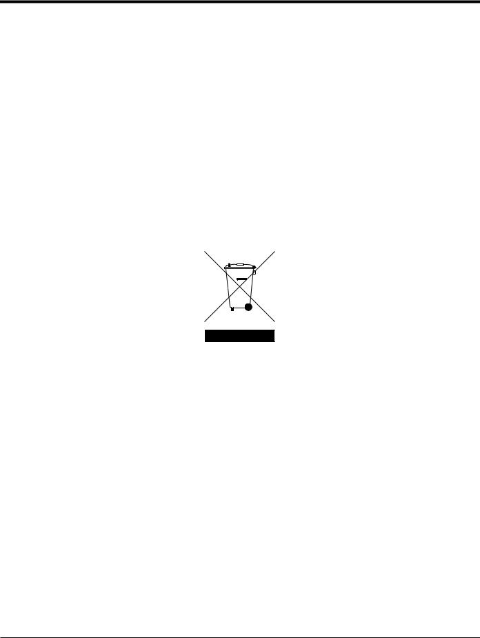
Because the relative location of the flowcell and the electronics enclosure is important, use the guidelines in this section to plan the XGM868i installation. Figure 1 shows a typical XGM868i enclosure and spoolpiece ready for insertion into a process line.
Figure 1: A Typical Model XGM868i System
1.3.1 Electronics Enclosure Location
The standard Model XGM868i electronics enclosure is a powder-coated, cast-aluminum, Type-7/4X explosion-proof enclosure; an optional stainless-steel enclosure is available. Typically, the enclosure is mounted as close as possible to the transducers. When choosing a site, make sure the location permits easy access to the electronics enclosure for programming, maintenance and service.
Note: For compliance with the European Union’s Low Voltage Directive (2006/95/EC), this unit requires an external power disconnect device such as a switch or circuit breaker. The disconnect device must be marked as such, clearly visible, directly accessible, and located within 1.8 m (6 ft) of the Model XGM868i.
|
2 |
DigitalFlow™ XGM868i Startup Guide |
![]()
Chapter 1. Installation
1.3.2 Flowcell Location
The pipeline flowcell consists of the flow rate transducers and any pressure and/or temperature transducers employed as part of the flow measurement system. Ideally, choose a section of pipe with unlimited access to the flowcell; for example, a long stretch of pipe that is above ground. However, if the flowcell is to be mounted on an underground pipe, dig a pit around the pipe to facilitate installation of the transducers.
1.3.3 Transducer Location
For a given fluid and pipe, the Model XGM868i’s accuracy depends primarily on the location and alignment of the transducers. In addition to accessibility, when planning for transducer location, adhere to the following guidelines:
1.Locate the transducers so that there are at least 20 pipe diameters of straight, undisturbed flow upstream and 10 pipe diameters of straight, undisturbed flow downstream from the measurement point. To ensure undisturbed flow, avoid sources of turbulence in the fluid such as valves, flanges, expansions and elbows; and dips or low spots in which condensed liquid may collect.
2.Because condensate or sediment at the bottom of the pipe may cause attenuation of the ultrasonic signal, locate the transducers on the side of a horizontal pipe, when possible. If limited pipe access necessitates top-mounted transducers and the sound beam path includes a reflection, shift the transducers to at least 10° off top dead center. This will minimize the influence of any sediment on the reflected ultrasonic signals.
1.3.4 Cable Lengths
Locate the electronics enclosure as close as possible to the flowcell/transducers, preferably directly on the flowcell. However, the factory can supply transducer cables up to 1,000 ft (300 m) in length for remote location of the electronics enclosure. If longer cables are required, consult the factory for assistance.
1.3.5 Temperature and Pressure Transmitters
When installing temperature and/or pressure transmitters in the flowcell, locate them downstream of the transducers. These transmitters should be positioned no closer to the Model XGM868i transducers than 2 pipe diameters and no further away from the transducers than 20 pipe diameters.
1.3.6 Transducer Cables
When installing the transducer cables, always observe established standard practices for the installation of electrical cables. Specifically, do not route transducer cables alongside high-amperage AC power lines or any other cables that could cause electrical interference. Also, protect the transducer cables and connections from the weather and corrosive atmospheres.
Note: When using non-GE cables to connect the flow rate transducers to the Model XGM868i electronics enclosure, the cables must have electrical characteristics identical to the GE cables. Type RG62 a/u coaxial cable should be used, and each cable must be the same length (within ±4 in.).
|
DigitalFlow™ XGM868i Startup Guide |
3 |
Chapter 1. Installation
1.4Installing a Flowcell
A flowcell is the section of pipe where the transducers are mounted. It can be created either by mounting the transducers on the existing pipeline or by mounting them on a spoolpiece. A spoolpiece is a separately manufactured pipe section, matched to the existing pipe, which contains ports for mounting the transducers. This approach allows the transducers to be aligned and calibrated before inserting the spoolpiece into the pipeline.
Figure 1 on page 2 shows a typical Model XGM868i spoolpiece, with a mounting bracket to hold the electronics enclosure. For detailed instructions on installing the transducers and/or spoolpiece, refer to the supplied drawings and the enclosed GE Gas Transducer Installation Guide (916-049).
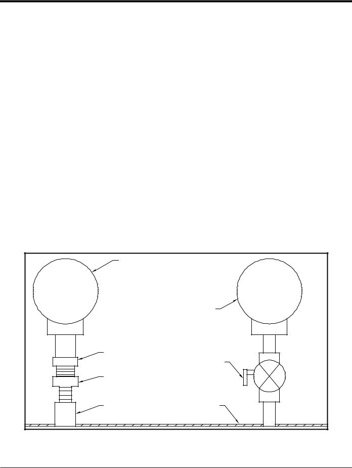
1.5Installing Temperature and Pressure Transmitters
Optional temperature and pressure transmitters may be installed near the ultrasonic transducer ports as part of the flowcell. Be sure to observe the siting requirements given earlier in this chapter. These transmitters should send a 0/4-20 mA signal to the Model XGM868i. In turn, the Model XGM868i must be fitted with a suitable option card to process the signals and to provide the required 24 VDC power to the transmitters. Any desired transmitters or sensors may be used, but they must have an accuracy equal to 0.5% of the reading or better.
Note: Resistive Thermal Devices (RTDs) are a good choice for measuring the temperature.
Typically, a 1/2” or 3/4” NPT female threaded port is used to mount the transmitters on the flowcell. If the pipeline is insulated, the coupling may need to be extended to provide convenient access. Of course, other types of mounting ports, including flanged ports, may be used for the transmitters.
Figure 2 shows a typical mounting arrangement for the pressure and temperature transmitters. The temperature sensor should protrude 1/4 to 1/2 way into the pipe.
|
Temperature Transmitter |
|
|
Pressure Transmitter |
|
|
RTD |
Isolation Valve |
|
Thermowell |
|
|
Coupling |
Flowcell Wall |
Figure 2: Typical Temperature/Pressure Transmitter Mounting
|
4 |
DigitalFlow™ XGM868i Startup Guide |

Chapter 1. Installation
1.6Mounting the XGM868i Electronics Enclosure
The standard Model XGM868i electronics package is housed in a Type-4X weather-resistant enclosure suitable for indoor or outdoor use. Refer to Figure 8 on page 23 for the mounting dimensions and the weight of this enclosure.
The Model XGM868i electronics enclosure is fitted with a mounting boss that has a single 3/4” NPTF threaded hole at its center and four 1/4-20 tapped holes at its corners. By using this mounting boss, the electronics enclosure may be mounted by any of the typical techniques shown in Figure 10 on page 25.
WARNING! Proper grounding of the XGM868i chassis is required to prevent the possibility of electric shock. See Figure 10 on page 25 for the location of the chassis grounding screw.
IMPORTANT: Since the IREX keys do not work properly in direct sunlight, be sure to position the XGM868i with an optional sunshield or out of direct sunlight.
1.7Making the Electrical Connections
This section contains instructions for making all the necessary electrical connections to the Model XGM868i flow transmitter. Refer to Figure 10 on page 25 for a complete wiring diagram.
Except for the power connector, all electrical connectors are stored on their terminal blocks during shipment and may be removed from the enclosure for more convenient wiring. Simply, feed the cables through the conduit holes on the side of the enclosure, attach the wires to the appropriate connectors and plug the connectors back onto their terminal blocks.
!ATTENTION EUROPEAN CUSTOMERS!
To meet CE Mark requirements, all cables must be installed as described in Appendix A,
CE Mark Compliance.
Refer to Figure 3 on page 6 and prepare the Model XGM868i for wiring by completing the following steps:
|
DigitalFlow™ XGM868i Startup Guide |
5 |
Chapter 1. Installation
1.7Making the Electrical Connections (cont.)
WARNING! Always disconnect the line power from the Model XGM868i before removing either the front cover or the rear cover. This is especially important in a hazardous environment.
1.Disconnect any existing power line from its source.
2.Loosen the set screw on the rear cover.
3.Place a rod or long screwdriver across the cover in the slots provided, and rotate the cover counterclockwise until it comes free from the enclosure.
4.Install any required cable clamps in the appropriate conduit holes around the side of the enclosure.
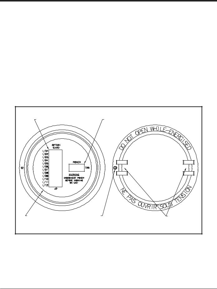
5.Note the labels inside the rear cover to assist in wiring the power and option card connections. Also, Figure 11 on page 26 shows the rear cover option card labels for every available option card configuration.
Proceed to the appropriate section of this chapter to make the desired wiring connections.
|
Option Card Connections |
Power Connections |
|
|
Wiring Label |
Set Screw |
Slots |
|
Inside View |
Outside View |
Figure 3: Rear Cover with Connection Labels
|
6 |
DigitalFlow™ XGM868i Startup Guide |

Chapter 1. Installation
1.7.1 Wiring the Line Power
The Model XGM868i may be ordered for operation with power inputs of 100-120 VAC, 220-240 VAC, or 12-28 VDC. The label on the side of the electronics enclosure lists the meter’s required line voltage and power rating. The fuse size is listed in Chapter 4, Specifications. Be sure to connect the meter only to the specified line voltage.
Note: For compliance with the European Union’s Low Voltage Directive (2006/95/EC), this unit requires an external power disconnect device such as a switch or circuit breaker. The disconnect device must be marked as such, clearly visible, directly accessible, and located within 1.8 m (6 ft) of the Model XGM868i.
Note: Only use Class 2 Rated Power supply for line power connection to DC instrument.
Refer to Figure 10 on page 25 to locate terminal block TB5 and connect the line power as follows:
WARNING! Improper connection of the line power leads or connecting the meter to the incorrect line voltage may damage the unit. It may also result in hazardous voltages at the flowcell and associated piping as well as within the electronics enclosure.
1.Prepare the line power leads by trimming the line and neutral AC power leads (or the positive and negative DC power leads) to a length 0.5 in. (1 cm) shorter than the ground lead. This ensures that the ground lead is the last to detach if the power cable is forcibly disconnected from the meter.
2.Install a suitable cable clamp in the conduit hole indicated in Figure 10 on page 25. If possible, avoid using the other conduit holes for this purpose, to minimize any interference in the circuitry from the AC power line.
!ATTENTION EUROPEAN CUSTOMERS!
To meet CE Mark requirements, all cables must be installed as described in Appendix A,
CE Mark Compliance.
3.Strip 1/4 in. of insulation from the end of each of the three power line leads.
4.Route the cable through the conduit hole and connect the line power leads to terminal block TB5, using the pin number assignments shown in Figure 10 on page 25.
5.Leaving a bit of slack, secure the power line with the cable clamp.
WARNING! Make sure both covers, with their o-ring seals, are installed and the set screws tightened before applying power in a hazardous environment.
CAUTION! The transducers must be properly wired before applying power to the meter.
Proceed to the next section to continue the initial wiring of the Model XGM868i flow transmitter.
|
DigitalFlow™ XGM868i Startup Guide |
7 |

Chapter 1. Installation
1.7.2 Wiring the Transducers
Before wiring the XGM868i transducers, complete the following steps:
•disconnect the main power from the electronics enclosure
•remove the rear cover and install all required cable clamps
Based on the location of the electronics enclosure, proceed to the appropriate sub-section for detailed instructions.
1.7.2a Flowcell-Mounted Enclosure
For an electronics enclosure mounted directly on the flowcell, wire the transducers as follows:
WARNING! Before connecting the transducers, take them to a safe area and discharge any static buildup by shorting the center conductor of the transducer cables to the metal shield on the cable connector.
Note: For transducer frequencies below 2 MHz, the cable lengths given for a pair of transducers must be within 4 in. (10 cm) of each other. If the transducer frequency exceeds 2 MHz, the cable lengths must be within 0.5 in. (1.25 cm) of each other.
1.Locate the CH1 transducer cables and connect them to the two CH1 transducers in the flowcell. Feed the free ends of the cables through the selected conduit hole in the electronics enclosure.
2.Refer to the wiring diagram in Figure 10 on page 25 and connect the transducer cables to terminal block J3. Then, secure the cable clamp.
Note: The RED cable leads are the SIG(+) leads and the BLACK cable leads are the RTN(-) leads.
!ATTENTION EUROPEAN CUSTOMERS!
To meet CE Mark requirements, all cables must be installed as described in Appendix A,
CE Mark Compliance.
3.For a 2-Channel XGM868i, repeat steps 1-2 to connect the CH2 transducers to terminal block J4. It is not required that both channels of a 2-Channel unit be connected.
4.If wiring of the unit has been completed, reinstall the rear cover on the enclosure and tighten the set screw.
Note: A channel must be activated before it can begin taking measurements. See Chapter 2, Initial Setup, for instructions.
|
8 |
DigitalFlow™ XGM868i Startup Guide |

Chapter 1. Installation
1.7.2b Remote-Mounted Enclosure
For a remote mounted enclosure, refer to the wiring diagram in Figure 10 on page 25 and the remote transducer wiring in Figure 12 on page 27, and complete the following steps:
WARNING! Before connecting the transducers, take them to a safe area and discharge any static buildup by shorting the center conductor of the transducer cables to the metal shield on the cable connector.
1.Using the pair of coaxial cables with BNC to BNC connectors supplied by the factory (or equivalent cables), connect both CH1 transducers to the preamplifier.
CAUTION! As part of maintaining the FM/CSA environmental rating (TYPE 4) on the remote preamplifier, thread sealant is required on all conduit entries.
2.If an optional lightning protector is being installed, connect it to the preamplifier as shown.
3.Using the supplied coaxial cables with BNC to flying lead connectors (or equivalent cables), route the cables through one of the conduit holes in the electronics enclosure and connect the preamplifier to terminal block J3. Secure the cable clamp.
Note: The RED cable leads are the SIG(+) leads and the BLACK cable leads are the RTN(-) leads.
!ATTENTION EUROPEAN CUSTOMERS!
To meet CE Mark requirements, all cables must be installed as described in Appendix A,
CE Mark Compliance.
4.For a 2-Channel XGM868i, repeat steps 3-5 to connect the CH2 transducers to terminal block J4 in the electronics enclosure. It is not required that both channels of a 2-Channel unit be connected.
5.If wiring of the unit has been completed, reinstall the rear cover on the enclosure and tighten the set screw.
Note: A channel must be activated before it can begin taking measurements. See Chapter 2, Initial Setup, for instructions.
Proceed to the next section to continue the initial wiring of the unit.
|
DigitalFlow™ XGM868i Startup Guide |
9 |

Chapter 1. Installation
1.7.3 Wiring Std 0/4-20 mA Analog Outputs
The standard configuration of the Model XGM868i flow transmitter includes two isolated 0/4-20 mA analog outputs (designated as outputs 1 and 2). Connections to these outputs may be made with standard twisted-pair wiring, but the current loop impedance for these circuits must not exceed 600 ohms.
To wire the analog outputs, complete the following steps:
1.Disconnect the main power and remove the rear cover.
2.Install the required cable clamp in the chosen conduit hole on the side of the electronics enclosure.
3.Refer to Figure 10 on page 25 for the location of terminal block J1 and wire the analog outputs as shown. Secure the cable clamp.
Note: Analog outputs 1 and 2 in the wiring diagram correspond to analog outputs A and B in Slot 0 in the XGM868i software.
!ATTENTION EUROPEAN CUSTOMERS!
To meet CE Mark requirements, all cables must be installed as described in Appendix A,
CE Mark Compliance.
4. If wiring of the unit has been completed, reinstall the rear cover on the enclosure and tighten the set screw.
WARNING! Make sure both covers, with their o-ring seals, are installed and the set screws tightened before applying power in a hazardous environment.
Note: Prior to use, the analog outputs must be set up and calibrated. See Chapter 1, Calibration, of the Service Manual for detailed instructions.
Proceed to the next section to continue the initial wiring of the unit.
|
10 |
DigitalFlow™ XGM868i Startup Guide |

Chapter 1. Installation
1.7.4 Wiring the Serial Port
The Model XGM868i flowmeter is equipped with an RS232 or an RS485 serial interface. An RS485 option is also available with MODBUS capability. When the MODBUS option is present, the XGM868i may also have the standard RS232 serial interface.
The serial port is used to transmit stored data and displayed readings to a personal computer by connecting the meter’s serial interface to the serial port of the PC. In addition, the Model XGM868i can receive and execute remote commands, using the Instrument Data Manager or PanaView software via this link.
For more information on serial communications refer to your EIA-RS Serial Communications manual (916-054). Proceed to the appropriate sub-section for wiring instructions.
!ATTENTION EUROPEAN CUSTOMERS!
To meet CE Mark requirements, all cables must be installed as described in Appendix A,
CE Mark Compliance.
1.7.4a Wiring the RS232 Interface
Use the serial port to connect the Model XGM868i flow transmitter to a printer, an ANSI terminal or a personal computer. The RS232 interface is wired as Data Terminal Equipment (DTE). Table 1 lists the standard cables available from the factory for this purpose.
Table 1: GE Serial Cables
|
Part Number |
PC Connector |
XGM868i Connector |
|
704-659 |
DB-25 Male |
Flying Leads (5) |
|
704-660 |
DB-9 Male |
Flying Leads (5) |
|
704-661 |
DB-25 Female |
Flying Leads (5) |
|
704-662 |
DB-9 Female |
Flying Leads (5) |
Each of the cables listed in the table above is available in several standard lengths. However, a user-supplied cable may be used, if preferred. In either case, wire the XGM868i end of the serial cable in accordance with the pin designations listed in Table 2 on page 12.
|
DigitalFlow™ XGM868i Startup Guide |
11 |

Chapter 1. Installation
1.7.4a Wiring the RS232 Interface (cont.)
Refer to Figure 10 on page 25 to complete the following steps:
WARNING! Dangerous voltages exist within the electronics enclosure. Do not attempt to wire the unit until the main power has been disconnected
1. Disconnect the main power and remove the rear cover.
WARNING! The XGM868i must be moved to a safe environment before removing either cover.
2.Install the required cable clamp in the chosen conduit hole on the side of the electronics enclosure.
3.Use the information in Table 2 to construct a suitable cable for connecting the Model XGM868i to the external device. If desired, an appropriate cable may be purchased from the factory.
Table 2: RS232 Connection to DCE or DTE Device
|
DCE |
DCE |
DTE |
DTE |
|||
|
J1 |
Signal |
DB25 |
DB9 |
DB25 |
DB9 |
|
|
Pin # |
Description |
Pin # |
Pin # |
Pin # |
Pin # |
|
|
5 |
DTR (Data Terminal |
20 |
4 |
20 |
4 |
|
|
Ready) |
||||||
|
6 |
CTS (Clear to Send) |
4 |
7 |
5 |
8 |
|
|
7 |
COM (Ground) |
7 |
5 |
7 |
5 |
|
|
8 |
RX (Receive) |
2 |
3 |
3 |
2 |
|
|
9 |
TX (Transmit) |
3 |
2 |
2 |
3 |
|
4.Feed the cable’s flying leads through the conduit hole and wire it to terminal block J1. Connect the other end of the cable to the external serial device and secure the cable clamp.
After the wiring has been completed, consult the User’s Manual for the external device to configure it for use with the XGM868i.
|
12 |
DigitalFlow™ XGM868i Startup Guide |
![]()
Chapter 1. Installation
1.7.4b Wiring the RS485 Interface
Use the optional RS485 serial port to network multiple XGM868i flow transmitters to a single control system. As an option, the standard RS232 port on the XGM868i may be configured as a
two-wire, half-duplex RS485 interface.
IMPORTANT: The Model XGM868i must be configured at the factory for RS485 operation.
To wire the RS485 serial port, refer to Figure 10 on page 25 and complete the following steps:
WARNING! Dangerous voltages exist within the electronics enclosure. Do not attempt to wire the unit until the main power has been disconnected
1. Disconnect the main power and remove the rear cover.
WARNING! The XGM868i must be moved to a safe environment before removing either cover.
2.Install the required cable clamp in the chosen conduit hole on the side of the electronics enclosure.
3.Feed one end of the cable through the conduit hole, wire it to terminal block J1 and secure the cable clamp. Use the information in Table 3 to wire a suitable cable for connecting the XGM868i to the external device.
Table 3: RS485 Connections
|
J1 Pin # |
Signal Description |
|
9 |
Data + |
|
8 |
Data — |
|
7 |
Shield |
|
6 |
Not Used |
|
5 |
Not Used |
|
4 |
Not Used |
4. If wiring of the unit has been completed, reinstall the rear cover on the enclosure and tighten the set screw. Proceed to the next section to continue the initial wiring of the unit.
|
DigitalFlow™ XGM868i Startup Guide |
13 |

Chapter 1. Installation
1.7.5 Wiring the Option Cards
The Model XGM868i can accommodate one option card in Slot 1 and one option card in Slot 2. The following option card functions are available only in the combinations listed in Table 14 on page 63:
Alarm Relays (Slot 1)
Analog Inputs (Slot 1)
Totalizer/Frequency Outputs (Slot 1)
RTD Inputs (Slot 1)
Analog Outputs (Slot 1)
MODBUS Communications (Slot 2)
MODBUS/TCP Communications (Slot 2)
Ethernet (Slot 2)
Foundation Fieldbus (Slot 2)
Data Logging (Slot 2) — no wiring required
Wiring any option card installed in Slot 1 requires completion of the following general steps:
1.7.5a Preparing for Wiring
1.Disconnect the main power and remove the rear cover.
2.Install a cable clamp in the chosen conduit hole on the side of the electronics enclosure and feed a standard twisted-pair cable through this conduit hole.
3.Locate the 12-pin terminal block (J2) in Figure 10 on page 25 and wire the option card as indicated on the label inside the rear cover (see Figure 3 on page 6 and Figure 11 on page 26). Secure the cable clamp.
IMPORTANT: Because of the attached wiring label, all rear covers must remain with their original meters.
!ATTENTION EUROPEAN CUSTOMERS!
To meet CE Mark requirements, all cables must be installed as described in Appendix A,
CE Mark Compliance.
4. If wiring of the unit has been completed, reinstall the rear cover on the enclosure and tighten the set screw.
Note: Prior to use, the option card must be set up and calibrated. See Chapter 1, Programming Site Data, in the Programming Manual and Chapter 1, Calibration, in the Service Manual for detailed instructions.
For more specific instructions on particular option cards, proceed to the appropriate section(s) that follow.
|
14 |
DigitalFlow™ XGM868i Startup Guide |
Chapter 1. Installation
1.7.5b Wiring an Alarms Option Card
Each alarms option card includes two or four general-purpose Form C relays (designated as A, B, C and D).
The maximum electrical ratings for the relays are listed in Chapter 4, Specifications. Each of the alarm relays can be wired as either Normally Open (NO) or Normally Closed (NC).
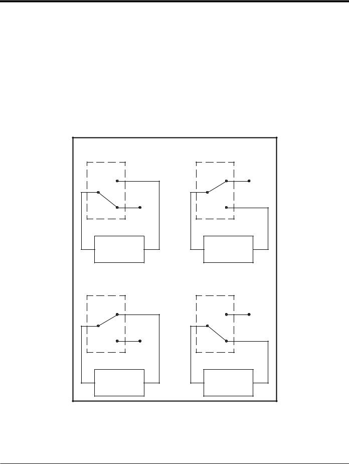
In setting up an alarm relay, it may be wired for either conventional or fail-safe operation. In fail-safe mode, the alarm relay is constantly energized, except when it is triggered or a power failure or other interruption occurs. See Figure 4 for the operation of a NO alarm relay in both conventional and fail-safe mode.
Before making any connections, complete the steps in Preparing for Wiring on page 14. Connect each alarm relay in accordance with the wiring instructions shown on the label inside the rear cover (see Figure 3 on page 6 and Figure 11 on page 26).
|
Conventional, |
Fail-Safe, |
|
not triggered |
not triggered |
|
NO |
NO |
|
C |
C |
|
NC |
NC |
|
Alarm |
Alarm |
|
Monitoring |
Monitoring |
|
Device |
Device |
|
Conventional, |
Fail-Safe, |
|
triggered |
triggered or power failure |
|
NO |
NO |
|
C |
C |
|
NC |
NC |
|
Alarm |
Alarm |
|
Monitoring |
Monitoring |
|
Device |
Device |
Figure 4: Conventional and Fail-Safe Operation
|
DigitalFlow™ XGM868i Startup Guide |
15 |
Chapter 1. Installation
1.7.5c Wiring a 0/4-20 mA Analog Inputs Option Card
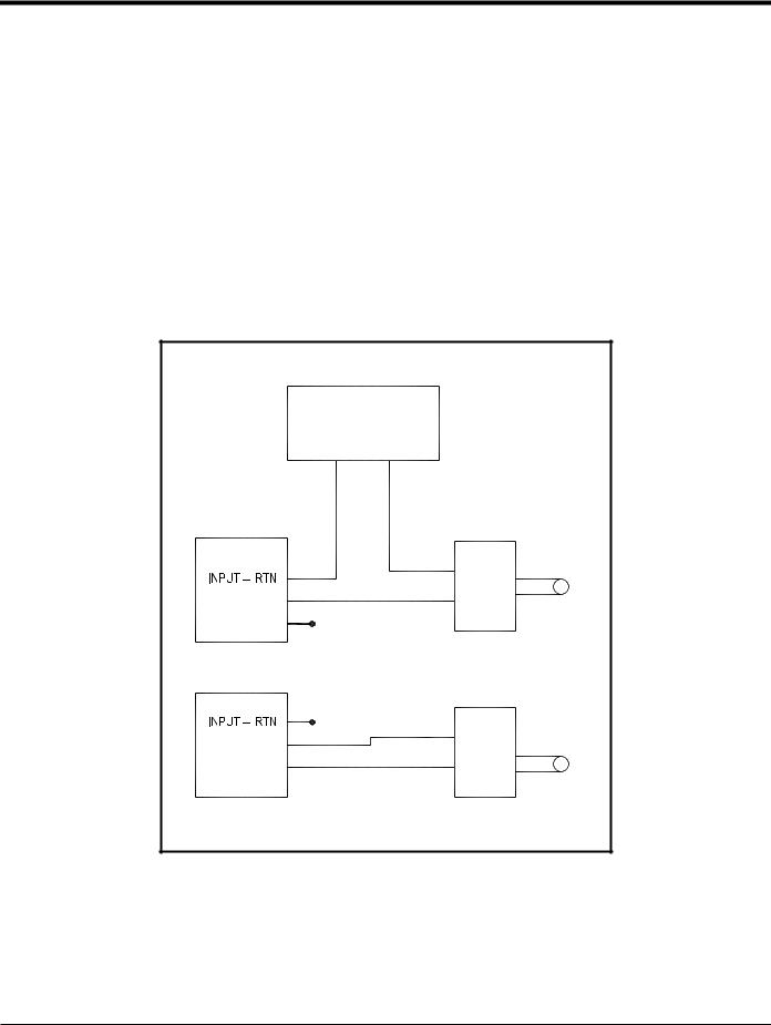
To calculate the standard flow rates, the Model XGM868i requires accurate temperature and pressure data from the measurement site. Transmitters installed in the flowcell can provide this information via an optional 0/4-20 mA analog inputs option card. This option card includes two or four isolated 0/4-20 mA analog inputs (designated as A, B, C and D), each of which includes a 24 VDC power supply for loop-powered transmitters. Either input may be used to process the temperature signal, while the other input is used to process the pressure signal.
Note: To properly enter programming data into the meter, it is necessary to know which input is assigned to which process parameter. This information should be entered in Appendix B, Data Records.
The analog inputs, which have an impedance of 118 ohms, should be connected with standard twisted-pair wiring. Power to the transmitters may be supplied either by the integral 24 VDC power supply on the analog input option card or by an external power supply. Figure 5 shows typical wiring diagrams, with and without an external power supply, for one of the analog inputs.
|
With External Power Supply |
||
|
24 VDC |
||
|
POWER SUPPLY |
||
|
– |
+ |
|
|
Analog Input |
Transmitter |
|
|
+ IN |
Sensor |
|
|
INPUT + |
– OUT |
|
|
+24V |
||
|
Analog Input |
Transmitter |
|
|
INPUT + |
– OUT |
Sensor |
|
+24V |
+ IN |
|
|
With Internal Power Supply |
Figure 5: Analog Input Wiring Diagram
|
16 |
DigitalFlow™ XGM868i Startup Guide |
Chapter 1. Installation
1.7.5c Wiring a 0/4-20 mA Analog Inputs Option Card (cont.)
Before making any connections, complete the steps in Preparing for Wiring on page 14. Wire the analog inputs as shown on the label in the rear cover (see Figure 11 on page 26).
Note: The analog inputs option card can be calibrated with the Model XGM868i’s built-in analog outputs. However, be certain that the analog outputs have been calibrated first. See Chapter 1, Calibration, in the Service Manual for the appropriate procedures.
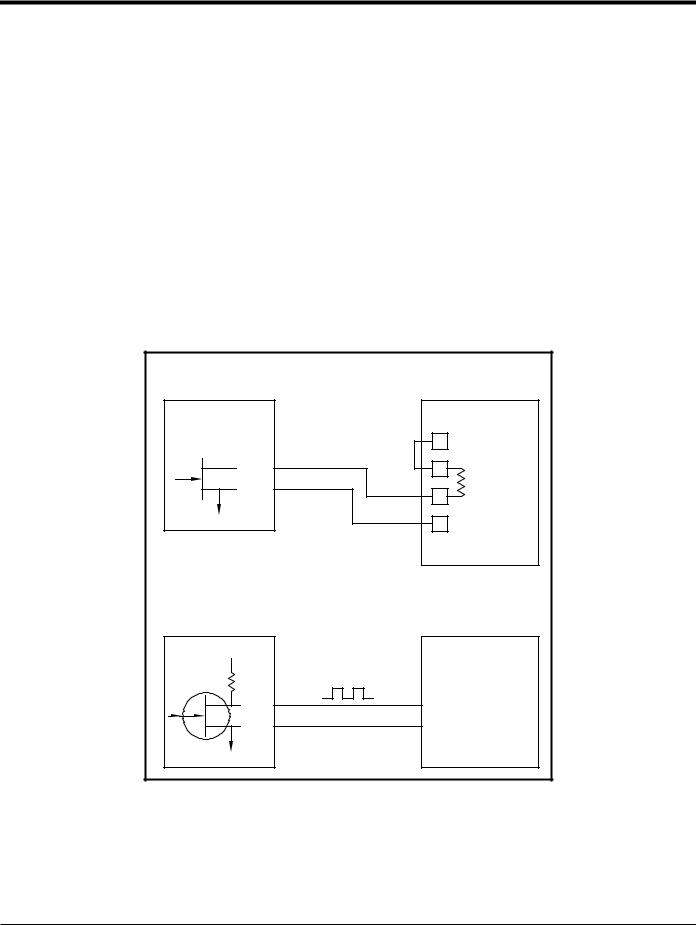
1.7.5d Wiring a Totalizer/Frequency Outputs Option Card
Each totalizer/frequency outputs option card provides two or four outputs (designated as A, B, C, and D) that can be used as either totalizer or frequency outputs.
Before making any connections, complete the steps in Preparing for Wiring on page 14. Then, wire this option card in accordance with the connections shown on the label in the rear cover (see Figure 3 on page 6 and Figure 11 on
page 26). Figure 6 shows sample wiring diagrams of a totalizer output circuit and a frequency output circuit. Refer to Electrical Specifications on page 56 for load and voltage requirements.
|
Totalizer Output |
||
|
Transmitter |
Pulse Counter |
|
|
Volts + |
||
|
(Int. Pwr. Sup.) |
||
|
OUT |
Load |
|
|
RTN |
||
|
Volts – |
||
|
(Common) |
||
|
Frequency Output |
||
|
Transmitter |
Frequency Counter |
|
|
+5V |
||
|
200: |
||
|
OUT |
IN |
|
|
RTN |
Common |
Figure 6: Totalizer/Frequency Outputs Wiring
|
DigitalFlow™ XGM868i Startup Guide |
17 |

Chapter 1. Installation
1.7.5e Wiring an RTD Inputs Option Card
The Model XGM868i RTD (Resistance Temperature Device) inputs option card provides two or four direct RTD inputs (designated as A, B, C and D). Each RTD input requires three wires, and should be connected as shown on the label in the rear cover (see Figure 3 on page 6 and Figure 11 on page 26).
Note: Before making any connections, complete the steps in Preparing for Wiring on page 14.
1.7.5f Wiring a 0/4-20 mA Analog Outputs Option Card
The analog outputs option card includes two isolated 0/4-20 mA outputs (designated as A and B). Connections to these outputs may be made with standard twisted-pair wiring, but the total current loop impedance for these circuits must not exceed 1,000 ohms.
Before making any connections, complete the steps in Preparing for Wiring on page 14. Then, wire this option card with the connections shown on the label in the rear cover (see Figure 3 on page 6 and Figure 11 on page 26).
1.7.5g A Specific Example
To illustrate the procedures described in the previous sections for wiring the option cards, a specific example may prove helpful. Assume that a Model XGM868i is equipped with an option card numbered 703-1223-08. Table 14 on page 63 in Appendix B, Data Records, indicates that this option card includes two analog current inputs and two standard alarm relays.
By referring to Figure 11 on page 26, it is determined that the appropriate connection diagram for this option card is the second one from the left in the middle row (AI,HI). This label should also be found inside the rear cover of the XGM868i. Based on this information, wiring of the Input/Output connections to terminal block J2 should be completed as shown in Table 4.
Table 4: Wiring a 703-1223-08 Option Card
|
J2 Pin # |
Description |
Connection |
|
1 |
Alarm A |
Normally Open |
|
2 |
Alarm A |
Common |
|
3 |
Alarm A |
Normally Closed |
|
4 |
Alarm B |
Normally Open |
|
5 |
Alarm B |
Common |
|
6 |
Alarm B |
Normally Closed |
|
7 |
Out C |
+24 V to Input C |
|
8 |
Input C |
Signal (+) |
|
9 |
Input C |
Return (-) |
|
10 |
Out D |
+24 V to Input D |
|
11 |
Input D |
Signal (+) |
|
12 |
Input D |
Return (-) |
|
18 |
DigitalFlow™ XGM868i Startup Guide |

Chapter 1. Installation
1.7.5h Wiring the MODBUS Option Card
The MODBUS option card uses the RS485 standard for MODBUS communication. The MODBUS card must be installed in Slot 2. The RS485 standard allows up to 32 nodes (drivers and receivers) on one multidrop network, at distances up to 4,000 ft (1,200 m). GE recommends using 24-gauge (24 AWG) twisted-pair wire with a characteristic impedance of 120 ohms and 120-ohm termination at each end of the communications line.
Note: The MODBUS option card provides its own RS485 connections. Thus, the meter can have its serial port configured as RS232 and still provide RS485 MODBUS signals.
IMPORTANT: Because the MODBUS option card uses pins 1 and 2 on terminal block J2, only those option cards that do not use these pins may be installed in Slot 1, while a MODBUS card is installed in Slot 2. Specifically, only the option cards designated as “OI” and “OR” in Figure 11 on page 26 are compatible with the MODBUS option card.
To link the XGM868i to the control system (refer to Figure 7):
1.Connect the MODBUS – wire to pin #2, the inverting or negative connection.
2.Connect the MODBUS + wire to pin #1, the non-inverting or positive connection.
3.Pin #3 has no connection.
.
MODBUS +
MODBUS – 


N/C
Figure 7: The RS485 MODBUS Terminal Block Connector
|
DigitalFlow™ XGM868i Startup Guide |
19 |

Chapter 1. Installation
1.7.5i Wiring the MODBUS/TCP Interface
Customers can also use a modified XGM868i that provides a MODBUS/TCP interface to communicate to an internal network. An optional MODBUS/TCP card with a unique MAC (IP) address (installed only in slot 2) includes an RJ45 connector. To connect the MODBUS/TCP-enabled XGM868i to the network, insert the jack of an RJ45 cable into the RJ45 connector, route the cable through one of the conduit holes using an appropriate cable clamp, and wire the other end of the cable to the Ethernet network according to the manufacturer’s instructions. See Figure 13 on page 28.
Note: The MAC address for a specific XGM868i is included with customer documentation. For more information on setting up the MAC address, refer to Chapter 6 of the Programming Manual.
1.7.5j Wiring the Ethernet Interface
A modified XGM868i can use the Ethernet interface to communicate to a local area network. An optional Ethernet card with a unique MAC (IP) address (installed only in slot 2) includes an RJ45 connector. To connect the Ethernet-enabled XGM868i to the network, insert the jack of an RJ45 cable into the RJ45 connector, route the cable through one of the conduit holes using an appropriate cable clamp, and wire the other end of the cable to the Ethernet network according to the manufacturer’s instructions. An external connection is required between the Ethernet option card and the XGM868i’s RS232 connector, as shown in Table 5 and Figure 13 on page 28.
Note: The MAC address for a specific XGM868i is included with customer documentation. For more information on setting up the MAC address, refer to Appendix C of the Programming Manual.
Table 5: RS232 to Ethernet Interconnections
|
XGM868i Type |
Terminal Block |
Terminal Block |
|
RS232 on Rear |
TB1 on Ethernet |
|
|
Terminal |
Board |
Card |
|
TX |
Pin 1 |
|
|
RX |
Pin 2 |
|
|
COM |
Pin 3 |
|
|
20 |
DigitalFlow™ XGM868i Startup Guide |
 Loading…
Table of Contents for Panametrics DigitalFlow XGM868i:
-
Chapter 2. Displaying Data 42 DigitalFlow™ XGM868i Programming Manual 2.3.1.1 Displaying Multiple Process Parameters The procedure for displaying a single process parameter in a text screen may be repeated to simultaneously display multiple process parameters. To do so, proceed as follows: 1. Display the first process parameter in a text screen, as described in the previous section. 2. Repeat Step 1 for any desired additional process parameters, by double clicking on them i
-
DigitalFlow™ XGM868i Programming Manual 132 Options DisplayError Handling SLOT0 SLOT1 I/O (appears only if option card is installed) Off 0-20m 4-20m Channel +TOTL –TOTL TIME MDOTVEL VOLUM SS up SS do SNDSP T up +MASS –MASS REYN# Tot K PEAK% Qup Tdown DELTA AMPdn CNTup CNTdn P#up Qdown AMPup PRESR Z AcVOL StVOLP#dn TEMP Tsupr Rho Kelvn kPaVinst Tsat QUAL Input/Output Comm Port System See Figure 54See Figure 54 See Figure 54S
-
Appendix C. Programming the XGM868i Using PanaView™ 110 DigitalFlow™ XGM868i Programming Manual Note: The measurement units that appear in these prompts are those selected in the Global-System menu earlier in this section. 5. Enter a flow rate value for the Zero (low) end of the analog output range and click [Next Item]. 6. Enter a flow rate value for the Full (high) end of the analog output range and click [Next Item]. After responding to the above prompt, the meter returns to step
-
DigitalFlow™ XGM868i Programming Manual 113 Appendix C. Programming the XGM868i Using PanaView™ Option Card Alarm Relays Complete the following steps to set up the alarm relays of an option card installed in Slot 1 (refer to Figure 58 on page 132): 1. Double-click on the desired Output (A, B, C or D). Note: The set up of alarm A is used here as an example. Identical procedures would be used to set up the additional alarms. 2. Double-click on Off to disable Output A an
-
Appendix C. Programming the XGM868i Using PanaView™ 106 DigitalFlow™ XGM868i Programming Manual C.6.2a Setting Up Error Handling This menu option lets you set how the XGM868i will handle the outputs for measurements and average (two-path) measurements during an error condition. See Chapter 2, Error Codes , in the Service Manual for a discussion of the built-in error codes. 1. From the Input/Output option, highlight and double-click on the Error Handling option in the center pane. 2. Double-c
-
DigitalFlow™ XGM868i Programming Manual 85 Appendix C. Programming the XGM868i Using PanaView™ C.3 Adding the XGM868i (cont.) IMPORTANT: The Network ID number must match the Network ID programmed in the meter’s Communications menu. If the initialization is successful, the Meter Browser shows a listing similar to Figure 37. Figure 37: Updated Network Tree However, if the settings do not match, or there is some other di
-
DigitalFlow™ XGM868i Programming Manual 109 Appendix C. Programming the XGM868i Using PanaView™ Analog Outputs (cont.) Note: All the options shown below will appear only if Mass Flow is activated. Table 27: Available Measurement Parameters Option Bar Description Good Bad Velocity Displays the flow velocity. N.A. N.A. Volumetric Displays the volumetric flow. N.A. N.A. FWD Total Displays the forward totalized v
-
Appendix C. Programming the XGM868i Using PanaView™ 88 DigitalFlow™ XGM868i Programming Manual C.4 Entering the User Program Using PanaView (cont.) Figure 42: Pipe Parameters Option in the Site Edit Menu c. Do one of the following: Click on [ Next Item] to proceed to the next menu item, or Click on [ Previous Item] to return back through the menu to a previous item.
-
Appendix B. Data Records 74 DigitalFlow™ XGM868i Programming Manual B.2 Option Cards Installed Whenever an option card is installed or changed in the Model XGM868i flow transmitter, record the type of card and any additional setup information in the appropriate row of Table 15. Table 15: Option Cards Installed Slot # Type of Option Card Additional Setup Information 0 Analog Outputs (A, B) 1 2
-
Chapter 1. Programming Site Data 30 DigitalFlow™ XGM868i Programming Manual 1.9.2.8 Frequency Outputs The frequency output issues a continuous signal with a frequency proportional to the selected measurement. Refer to Figure 31 on page 72, and complete the following steps to set up the totalizer outputs of an option card installed in SLOT 1: Accessing the Frequency Output 1. In the Keypad Program , scroll to PROG and press [Enter]. 2. In the PROG menu, scroll to GLOBL and press [Enter]. 3. In
-
Chapter 1. Programming Site Data 18 DigitalFlow™ XGM868i Programming Manual 1.9.1 Entering Global System Data This menu enables you to select the system units that the XGM868i will use when channel data is added, subtracted or averaged together. 1. In the Keypad Program , scroll to PROG and press [Enter]. 2. In the PROG menu, scroll to GLOBL and press [Enter]. 3. In the Global PROGRAM menu, scroll to SYSTM and press [Enter]. 4. At the System Units prompt, scroll to Eng to display measurements in English units or
-
panametrics.com Flow 910-197P F Jul 2021 DigitalFlow™ XGM868i Panametrics General-Purpose Gas Flow Transmitter (1 & 2 Channel) Programming Manual
-
Appendix C. Programming the XGM868i Using PanaView™ 102 DigitalFlow™ XGM868i Programming Manual C.6 Entering Data in the Global Menu The Global menu is used to enter information that is not specific to any of the individual channels. Information programmed via this menu is used to enter several general system parameters (e.g., English or metric units). For meters with 2 channels, this menu is also used to compute parameters such as the sum, difference or average of the channel 1 and chann
-
DigitalFlow™ XGM868i Programming Manual 69 Keypad Pgm. [Esc][Enter][Esc] PROG RESET CALIB CNTRS NO YES Reset Totals See Service Manual DARKN LITEN STORE ABORT CH2* GLOBLCH1 (* for 2-Channel meter only) See Figure 30 PIPE I/O SET UPSYSTMACTIV Off Burst Burst 1-Channel2-Channel Channel Status Site Status Skan Only Skan/Measure Skan/Measure Mode Fixed Slot1* BA TEMP INPUT ZERO CUTOFF (*only if input option is installed) B:LABEL FIXED TEMP. Fixed Slot1* PRESSURE INPUT (*only if input option is in
-
Chapter 2. Displaying Data 48 DigitalFlow™ XGM868i Programming Manual [no content intended for this page]
Questions, Opinions and Exploitation Impressions:
You can ask a question, express your opinion or share our experience of Panametrics DigitalFlow XGM868i device using right now.
- Manuals
- Brands
- GE Manuals
- Measuring Instruments
- DigitalFlow XGM868i
Manuals and User Guides for GE DigitalFlow XGM868i. We have 1 GE DigitalFlow XGM868i manual available for free PDF download: Startup Manual
Назначение
Расходомеры-счетчики газа и пара моделей XGF868i, XGM868i, XGS868i (далее -расходомеры-счетчики) предназначены для измерения скорости, объемного расхода (объема) природного, попутного и свободного нефтяного, факельного и других газов, массового расхода (массы) водяного пара, а также вычисления объемного расхода и объема попутного и свободного нефтяного, факельного газов, приведенных к стандартным условиям по ГОСТ 2939-63.
Описание
Расходомеры-счетчики состоят из ультразвуковых преобразователей и электронновычислительного блока (далее — ЭВБ).
Принцип действия расходомеров-счетчиков основан на ультразвуковом времяимпульсном методе измерений. Ультразвуковые преобразователи, установленные выше и ниже по течению потока, посылают и принимают кодированные ультразвуковые сигналы, проходящие через поток газа или пара. ЭВБ по разности времен перемещения импульсов по направлению потока и против него, используя методы цифровой обработки в сочетании с современными способами кодирования и корреляционного детектирования сигнала, рассчитывает скорость потока. На основе измеренной скорости потока и диаметра измерительного трубопровода ЭВБ проводит расчет объемного расхода и объема газа или пара.
Для обеспечения максимальной точности могут использоваться двухканальные модели, которые могут быть установлены для двух лучевого измерения скорости, объемного расхода (объема) в одном месте трубопровода, а так же может применяться для измерения скорости, объемного расхода (объема) в двух различных трубопроводах или в двух различных точках одного трубопровода. Расходомеры-счетчики с врезными ультразвуковыми преобразователями могут комплектоваться измерительным участком. Для обеспечения доступа к ультразвуковым преобразователям расходомеры-счетчики могут комплектоваться запорной арматурой, позволяющей извлекать ультразвуковые преобразователи без остановки технологического процесса при рабочем давлении. Расходомеры-счетчики могут использоваться во взрывоопасных зонах.
Расходомеры-счетчики имеют аналоговые токовые входы для подключения преобразователей давления и температуры.
Расходомеры-счетчики модели XGF868i (далее — XGF868i) предназначены для измерения скорости, объемного расхода (объема) попутного и свободного нефтяного, факельного газов при рабочих условиях, а также при использовании преобразователей давления и температуры, вычисления объемного расхода (объема) попутного и свободного нефтяного, факельного газов, приведенных к стандартным условиям по ГОСТ 2939-63. XGF868i позволяет измерять массовый расход и массу факельного газа. Ультразвуковые преобразователи могут быть установлены в измерительный участок или непосредственно в технологическую линию, используя процедуру «горячей или холодной врезки».
Расходомеры-счетчики модели XGM868i (далее — XGM868i) общепромышленного назначения предназначены для измерения скорости, объемного расхода (объема) природного, попутного и свободного нефтяного, факельного газов и иных газов с известными физическими свойствами при рабочих условиях, а также при использовании преобразователей давления и температуры вычисления объемного расхода (объема) природного, попутного и свободного нефтяного, факельного газов, приведенного к стандартным условиям по ГОСТ 2939-63. Расчет физических свойств газа в XGM868i осуществляется по методике ГСССД МР-113-03 или ГОСТ30319.0 — ГОСТ 30319.3. XGM868i позволяет измерять массовый расход и массу природного, попутного и свободного нефтяного, факельного газов. Ультразвуковые преобразователи могут быть установлены в измерительный участок или непосредственно в технологическую линию, используя процедуру «горячей или холодной врезки».
Расходомеры-счетчики моделей XGS868i (далее — XGS868i) предназначены для измерения скорости, объемного расхода (объема) насыщенного и перегретого пара, а также при использовании преобразователей давления и температуры расчета массового расхода (массы) насыщенного и перегретого пара.
XGF868i, XGM868i, XGS868i изготавливаются во взрывобезопасном исполнении.
ЭВБ расходомеров-счетчиков обеспечивают выполнение следующих функций:
— цифровая обработка сигналов поступающих с ультразвуковых преобразователей;
— измерение и преобразование входных аналоговых сигналов постоянного тока от преобразователей давления и температуры;
— обработка, отображение и хранение измерительной информации и настроечных параметров расходомеров-счетчиков;
— передача измерительной информации по аналоговым и различным цифровым интерфейсам;
— защита от преднамеренных и непреднамеренных изменений и несанкционированного доступа.
В комплект поставки расходомеров-счетчиков может входить программный пакет PanaView, для установки на операторские и инженерные станции с установленной операционной системой Windows. Программный пакет PanaView позволяет производить следующие операции:
— загружать в расходомеры-счетчики и сохранять из расходомеров-счетчиков конфигурационные данные;
— формировать протоколы и графики, основываясь на измерительной информации хранящейся в расходомерах-счетчиках;
— отображать и строить графики по текущим значениям измеряемых параметров. Программный пакет PanaView реализует протоколы связи IDM и PanaLink и
поддерживает коммуникационные интерфейсы связи RS232, RS485, Ethernet и инфракрасный интерфейс связи.
Программное обеспечение
Расходомеры-счетчики имеют встроенное программное обеспечение (далее — ПО). Защита ПО расходомеров-счетчиков от несанкционированного доступа с целью изменения параметров, влияющих на метрологические характеристики, осуществляется путем аутентификации (введением пароля администратора), ведения доступного только для чтения журнала событий и ошибок. Возможность внесения преднамеренных и непреднамеренных изменений в ПО расходомеров-счетчиков исключается наличием в расходомерах-счетчиках функции определения целостности ПО при включении и ограничением свободного доступа к цифровым интерфейсам связи.
Идентификация ПО расходомеров-счетчиков осуществляется путем отображения на дисплее расходомера-счетчика или подключенного к нему инженерного персонального компьютера структуры идентификационных данных, содержащей номер версии ПО расходомера-счетчика. Идентификационные данные ПО расходомеров-счетчиков приведены в таблице 1.
|
Таблица 1 — |
Идентификационные данные ПО расходомеров-счетчиков |
|||
|
Модель расходомера -счетчика |
Идентификационное наименование ПО |
Номер версии ПО |
Цифровой идентификатор ПО |
Алгоритм вычисления цифрового идентификатора ПО |
|
XGF868i |
GF868.BIN |
Y4FF |
6DFD |
CRC-16 |
|
XGM868i |
XGM868.BIN XGM868.HRT.BIN XGM868i.BIN |
Y3FM Y3C.HRT Y4FM |
9347 2CE6 6F43 |
CRC-16 |
|
XGS868 |
XGS868.BIN XGS868i.BIN |
Y3FS Y4FS |
91BF 6F1F |
CRC-16 |
|
Примечание — Номер версии ПО и цифровой идентификатор ПО зависят от модели и комплектации расходомеров-счетчиков и могут быть изменены заводом изготовителем при выпуске из производства. |
ПО расходомеров-счетчиков имеет уровень защиты высокий по Р 50.2.077-2014.
Технические характеристики
Метрологические и технические характеристики расходомеров-счетчиков приведены в таблицах 2,3.
Т аблица 2 — Метрологические и технические характеристики XGF868i и XGM868i_
|
Наименование характеристики |
Модификация |
|
|
XGF868i |
XGM868i |
|
|
Диапазон измерений скорости, м/с |
от 0,03 до 120* |
от 0,03 до 46 |
|
Максимальное количество каналов измерения скорости и объемного расхода |
2 |
|
|
Наружный диаметр измерительного трубопровода (D), мм |
от 50 до 3000 |
|
|
Температура измеряемой среды, °С |
от минус 70 до 150 (от минус 70 до 280)** (от минус 220 до 120)** (от минус 190 до 450)** |
от минус 50 до 150 (от минус 190 до 450)** |
|
Абсолютное давление измеряемой среды, МПа |
от 0,087 до 20 |
от 0,087 до 18,7 (24**) |
|
Пределы допускаемой относительной |
D<1500 мм D>1500 мм |
|
Наименование характеристики погрешности при измерении скорости, объемного расхода (объема), % — 1 канальное исполнение (V>0,3 м/с) — 2 канальное исполнение^>0,3 м/с) — 1 канальное исполнение (0,08<V<0,3 м/с) — 2 канальное исполнение (0,06<V<0,3 м/с) — 2 канальное исполнение при калибровке и поверке проливным методом (при V>1,5 м/с) в комплекте с измерительным участком ** |
Модификация |
|
|
XGF868i |
XGM868i |
|
|
±2 ±1,4 ±5 ±5 ±0,5** |
±5 ±3,5 |
±2 ±1 ±0,5** |
|
Пределы допускаемой приведенной погрешности аналоговых каналов ввода, % |
±0,1 |
±0,1 |
|
Пределы допускаемой приведенной погрешности аналоговых каналов вывода, % |
±0,1 |
±0,1 |
|
Пределы допускаемой относительной погрешности при вычислении объемного расхода (объема) попутного и свободного нефтяного или природного газов (в зависимости от модели), приведенного к стандартным условиям, (для AGA8-92DC), % |
±0,01 (±0,03) |
|
|
Температура окружающей среды ЭВБ, °С |
от минус 40 до 60 |
от минус 40 до 60 |
|
Температура хранения, °С |
от минус 55 до 75 |
|
|
Максимальная длина кабеля от преобразователя к вычислителю, м |
330 |
|
|
Входные сигналы: |
аналоговый (от 0/4 до 20 мА); импульсный; частотный. |
|
|
Выходные сигналы: |
аналоговый (от 0/4 до 20 мА); импульсный; частотный, дискретный. |
|
|
Цифровые интерфейсы связи |
RS232, RS485**, OPC сервер**, Modbus RS485 or TCP/IP**, Ethernet TCP/IP**, OPC server**, Foundation FieldBus** |
|
|
Электропитание: — напряжение переменного тока — напряжение постоянного тока |
220 В (±10%) 50±1 Гц от 12 до 48 В |
220 В (±10%) 50±1 Гц от 12 до 28 В |
|
Потребляемая мощность, не более, Вт |
20 |
|
|
Защита ЭВБ по ГОСТ 14254-96 |
IP66 |
IP66 |
|
Маркировка взрывозащиты ЭВБ |
1ExdIICT6/T5 |
1ExdIICT6/T5 |
|
Г абаритные размеры ЭВБ, мм |
208*208×168 |
208x208x168 |
|
Масса ЭВБ, кг |
4,5 |
4,5 |
|
Средний срок службы, лет, не менее |
10 |
|
|
* — диапазон измерения скорости определяется конструктивным исполнением; ** — комплектуется по спецзаказу |
|
Наименование |
Характеристики |
|
Диапазон измерений скорости, м/с |
от 0,03 до 46 |
|
Максимальное количество каналов измерения скорости и объемного расхода |
2 |
|
Наружный диаметр измерительного трубопровода (D), мм |
от 50 до 1200 |
|
Температура измеряемой среды, °С |
от минус 50 до 150 (от минус 190 до 450)* |
|
Абсолютное давление измеряемой среды, МПа |
от 0,087 до 18,7 (24*) |
|
Пределы допускаемой относительной погрешности при измерении скорости (V>0,9 м/с), объемного расхода (объема), % — 1 канальное исполнение — 2 канальное исполнение |
±2 ±1 |
|
Пределы допускаемой приведенной погрешности аналоговых каналов ввода, % |
±0,1 |
|
Пределы допускаемой приведенной погрешности аналоговых каналов вывода, % |
±0,1 |
|
Пределы допускаемой относительной погрешности при вычислении массового расхода (массы) насыщенного и перегретого пара, % |
±0,05 |
|
Температура окружающей среды ЭВБ, °С |
от минус 40 до 60 |
|
Температура хранения, °С |
от минус 55 до 75 |
|
Максимальная длина кабеля от преобразователя к вычислителю, м |
330 |
|
Входные сигналы: |
аналоговый (от 0/4 до 20 мА), импульсный, частотный |
|
Выходные сигналы: |
аналоговый (от 0/4 до 20 мА), импульсный, частотный, дискретный |
|
Цифровые интерфейсы связи |
RS232, RS485*, OPC сервер*, Modbus RS485 or TCP/IP*, Ethernet TCP/IP*, OPC server*, Foundation FieldBus* |
|
Электропитание: — напряжение переменного тока — напряжение постоянного тока |
220 В (±10%) 50±1 Гц от 12 до |
|
Потребляемая мощность, не более, Вт |
20 |
|
Защита ЭВБ по ГОСТ 14254-96 |
IP 66 |
|
Маркировка взрывозащиты ЭВБ |
1ExdIICT6/T5 |
|
Г абаритные размеры ЭВБ, мм |
208x208x168 |
|
Масса ЭВБ, кг |
4,5 |
|
Средний срок службы, лет, не менее |
10 |
|
* — комплектуется по спецзаказу |
Знак утверждения типа
наносится на титульный лист Руководства по эксплуатации типографским способом и на корпус ЭВБ расходомеров-счетчиков в виде голографической наклейки.
Комплектность
Комплексность поставки расходомеров-счетчиков приведена в таблице 4.
Таблица 4 — Комплектность
|
Наименование |
Количество |
|
ЭВБ расходомера-счетчика |
1 экз. |
|
Комплект ультразвуковых преобразователей |
1 или 2 комплекта^ |
|
Комплект запорной арматуры |
1 или 2 комплекта2-* |
|
Соединительные кабели |
1 комплект |
|
Измерительный участок ИТ |
1 экз 2) |
|
Программный пакет PanaView для конфигурирования, параметризации и диагностики расходомеров-счетчиков |
1 экз 2) |
|
Руководство по эксплуатации: — модель XGF868i. Руководство по эксплуатации. 910-198P, 910198S, — модель XGM868i. Руководство по эксплуатации. 914-197 — модель XGS868i. Руководство по эксплуатации. 910-196UE |
1 экз.3) |
|
Расходомеры-счетчики газа и пара моделей XGF868i, XGM868i, XGS868i. Методика поверки. |
1 экз. |
|
1) — Тип и количество ультразвуковых преобразователей выбирается в зависимости от требуемой точности измерений, типа измеряемой среды и условий эксплуатации расходомера-счетчика 2) — Поставляется дополнительно по заказу 3) — В зависимости от модели |
Поверка
осуществляется по документу МП-101-30151-2014 «Расходомеры-счетчики газа и пара моделей XGF868i, XGM868i, XGS868i, GF868, GM868, GS868, GC868, PT878GC, CTF878, IGM878. Методика поверки», утвержденному ГЦИ СИ ООО «Метрологический центр СТП» 8 февраля 2014 года.
Перечень основных средств поверки:
— поверочная расходомерная установка, диапазон воспроизводимого объемного расхода должен соответствовать рабочему диапазону поверяемого расходомера-счетчика, пределы допускаемой относительной погрешности ±0,3%;
— калибратор многофункциональный MC5-R, диапазон воспроизведения силы постоянного тока от 0 до 25 мА, пределы допускаемой погрешности воспроизведения ±(0,02% показания + 1,5 мкА); диапазон измерения силы постоянного тока ±100 мА, пределы допускаемой погрешности измерения ±(0,02 % показания + 1,5 мкА); диапазон измерения частотного сигнала от 0,0028 Гц до 50 кГц, пределы допускаемой относительной погрешности ±0,01%; счет импульсов до 9999999 имп., погрешность подсчета импульсов отсутствует;
— штангенциркуль ШЦЦ-I -300, диапазон измерений от 0 до 300 мм, пределы допускаемой абсолютной погрешности ±0,03 мм;
— нутромер микрометрический НМ600, диапазон измерений от 75 до 600 мм, пределы допускаемой абсолютной погрешности ±(4-15) мкм;
— нутромер микрометрический НМ1250, диапазон измерений от 150 до 1250 мм, пределы допускаемой абсолютной погрешности ±(6-20) мкм;
— термогигрометр ИВА-6А-П-Д, диапазон измерения влажности от 0 до 98 %, пределы абсолютной погрешности ±2%; диапазон измерения температуры от минус 40 до 60°С, пределы абсолютной погрешности ±1°С; диапазон измерения атмосферного давления от 30 до 110 кПа, пределы абсолютной погрешности ±0,25кПа.
Сведения о методах измерений
Метод измерения расходомеров-счетчиков описан в руководствах по эксплуатации расходомеров-счетчиков.
Нормативные документы, устанавливающие требования к расходомерам-счетчикам газа и пара моделей XGF868i, XGM868i, XGS868i
1 ГОСТ 8.618-2006 ГСИ. Государственная поверочная схема для средств измерений объемного и массового расходов газа
2 ГОСТ 14254-96 Степени защиты, обеспечиваемые оболочками (Код IP)
Рекомендации к применению
— при выполнении государственных учетных операций и учете количества энергетических ресурсов;
— при осуществлении торговли.