Личный кабинет
Авторизация
Регистрация
RUB, руб.
- EUR, €
- RUB, руб.
Сервис-партнёр RATIONAL
Запчасти Rational, аксессуары. Гарантийный ремонт. Проддажа пароконвектоматов по специальным программам.
Рады общению с 10 до 19 часов в рабочие дни
+79049845111
0
Корзина
Пустая
Главная страница » Инструкции pdf
Инструкции pdf

Руководство по эксплуатации пароконвектомата RATIONAL iCombi Pro с 2020 года.

Руководство по эксплуатации пароконвектомата RATIONAL iCombi Classic с 2020 года.

Руководство по эксплуатации пароконвектомата RATIONAL SelfCooking Center whitefficiency/ 5Senses 2011-2017

Руководство по эксплуатации пароконвектомата RATIONAL Combi Master Plus 2011-2017

Руководство по эксплуатации пароконвектомата RATIONAL SelfCooking Center 2004-2011

Руководство по эксплуатации пароконвектомата RATIONAL Combi Master 2004-2011

Книга рецептов для ручной эксплуатации
Воспользуйтесь уникальным опытом лучших шеф паворов.

Руководство по применению. Ночное приготовление, смешанная загрузка, вакуумная упаковка.
Коллектив отдыхает а оборудование работает

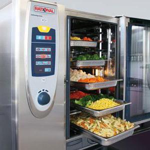
Руководство по применению. Finishing
Уникальные алгоритмы оптимизации процессов подготовки и подачи блюд.
Подготовка к банкету без стресса.

Моющие средства RATIONAL
Использование оригинальных моющих средств защитит ваше оборудование от вредных воздействий и обеспечит бесперебойную работу в течении всего срока эксплуатации.
Пароконвектомат – универсальное оборудование профессиональной кухни. С его помощью можно осуществить до 70% всех операций тепловой обработки пищи: обжарку, тушение, пассировку, запекание, разогрев и даже приготовление блюд на пару.
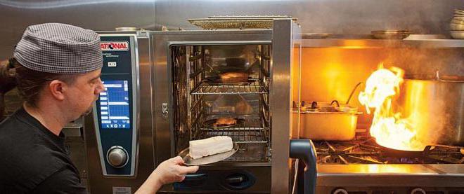
Видными представителями профессиональной кухонной техники этой категории являются пароконвектоматы Rational. На отечественном рынке продукция немецкой компании появилась в 2004 году и сразу зарекомендовала себя с лучшей стороны. История развития оборудования насчитывает более четырех десятков лет. За это время пароконвектоматы вплотную приблизились к идеалу кухонного оборудования.
Устройство пароконвектоматов
Компания Rational существует с 1976 года, ровно с того самого момента, когда господин Майстер изобрел первый в мире пароконвектомат. С тех пор конструкция кухонной техники претерпела значительные изменения. Однако в их устройстве по-прежнему можно выделить две основные секции: камеру для приготовления пищи и блок рабочего оборудования.
Внешне пароконвектоматы Rational представляют собой довольно массивные шкафы, выполненные из нержавеющей стали. На стенках камеры для приготовления пищи установлены нагревательные элементы, на дне имеется специальное сливное отверстие для удаления конденсата при обработке продуктов паром.
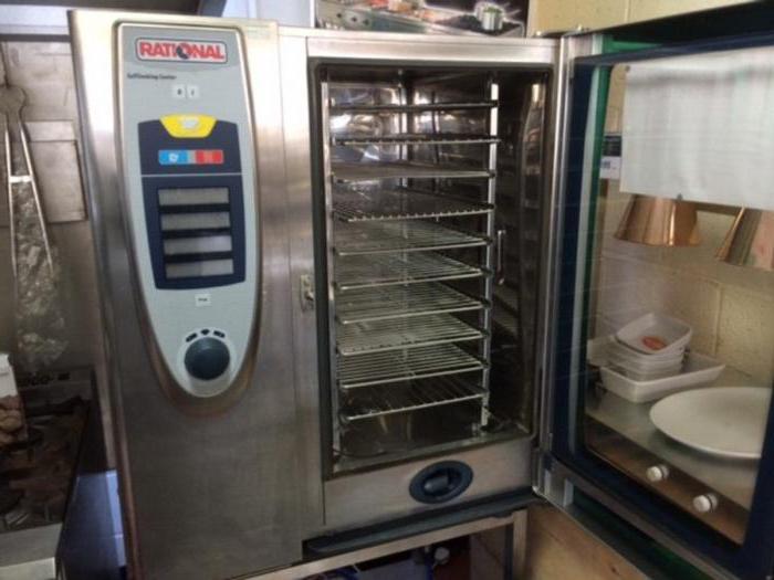
Камера герметично закрывается стальной дверцей с окном из трехслойного жаропрочного стекла. С его помощью повара могут наблюдать за процессом приготовления. Чтобы конденсат, образующийся на дверце, не стекал на пол во время открытия, предусмотрен специальный лоток. Внутри камеры встроен мощный вентилятор, который в одно мгновение доводит температуру рабочей среды до необходимого уровня.
Устройство парогенераторов
Все пароконвектоматы Rational поставляются со встроенным парогенератором, который вместе с автоматикой и пультом управления располагается в блоке рабочего оборудования. Встраиваемые парогенераторы могут быть двух типов: инжекторными и бойлерными.
В первом случае генерация пара происходит за счет распыления воды непосредственно на нагревательные ТЭНы камеры приготовления. Для сбора конденсата в такой технике предусмотрен коллектор и сливное отверстие. Плюсами инжекторных парогенераторов являются доступная цена, простая конструкция и малые габариты всей техники. К минусам можно отнести невозможность регулирования температуры пара.
Бойлерные пароконвектоматы Rational имеют отдельный парогенератор в виде бойлера. В нем при помощи магнитного клапана поддерживается постоянный уровень жидкости. Образование пара происходит за счет нагрева воды внутри емкости. К плюсам таких установок следует отнести высокую производительность и мощность, возможность нагрева пара до 130оС, а к минусам – образование накипи на нагревательных элементах бойлера, высокую стоимость и большие габариты.
Пароконвектоматы SelfCooking Center
Особого внимания среди всей линейки оборудования заслуживают модели SelfCooking Center, призванные учиться у мастера и думать вместе с поваром. Главную роль в этом агрегате играет блок автоматики и различные датчики определения температуры блюда, степени прожарки и подрумянивания.
Одним из представителей серии является пароконвектомат Rational SCC 101. В его программу встроены алгоритмы приготовления блюда индийской, китайской, японской, латиноамериканской кухонь.
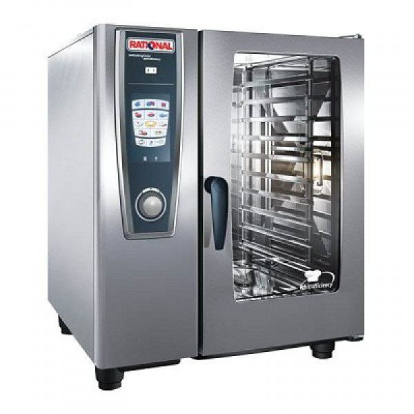
Но главной особенностью аппарата является его способность к обучению. Он запоминает предпочитаемую поваром технологию приготовления и заносит ее себе в память, анализирует и предлагает свой рецепт, а после поэтапно «расписывает» новую методику. Однако последнее слово всегда остается за человеком.
Особенности приготовления блюд
Каким бы опытным поваром вы ни были, перед началом работы с пароконвектоматом внимательно изучите инструкцию. Это позволит избежать травм, ожогов и порчи продуктов.
Но часто на пароконвектомат Rational инструкция по эксплуатации напечатана на немецком языке. Для тех, кто столкнулся с подобной проблемой, приведем основные положения из ее содержания:
- для равномерного нагрева пищи перед началом работы прогрейте рабочую камеру в течение 10-15 минут при температуре 130-140оС;
- оставляйте место между продуктами при их загрузке – так вы сократите время приготовления и расход электричества, добьетесь равномерной корочки;
- загружайте продукты максимально быстро, чтобы не изменились условия приготовления внутри рабочей камеры (влажность, давление), ведь это может привести к порче блюд;
- не прислоняйтесь к дверце, не приближайтесь лицом к смотровому окну слишком близко во избежание получения ожогов.
Перед началом работы с техникой производителем рекомендуется повторить элементарные правила техники безопасности при работе с тепловым оборудованием, а также изучить устройство пароконвектомата Rational. Это поможет избежать проблем.
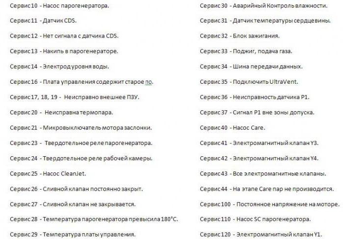
Коды ошибок пароконвектоматов
Как и любая другая умная техника, пароконвектоматы Rational при возникновении неисправностей сообщают об этом пользователю в виде кодов ошибки. Выяснение причины повреждения поможет как можно скорее исправить проблему и продолжить работу. На что обращать внимание при отказе в работе устройств серии SCC, SCC-WE и SCC 5 Senses, смотрите ниже.
Для устранения неисправностей оборудования лучше всего вызвать квалифицированного специалиста. Но когда это невозможно, внимательно изучите коды ошибок и действуйте в соответствии с инструкцией по эксплуатации.
Ошибки пароконвектоматов серий СМ и СМ Р
Ошибки пароконвектомата Rational, принадлежащего линейке моделей СМ или СМ Р, немного отличаются от представленных ранее. Эта группа оборудования более точно указывает на причину неисправности и помогает ее устранить.
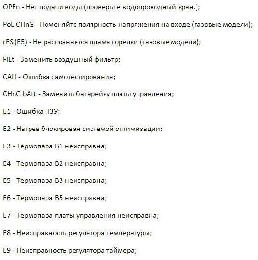
В некоторых случаях во время готовки могут появиться нетипичные коды ошибок. Одной из таковых является Е34, которая является «комбинированным» сигналом. Цифра 3 сообщает об ошибке шины данных, а второе число – в каком именно элементе произошла ошибка. Так, 4 указывает на верхний блок зажигания, а 8 – на нижний; число 2 – на нижний мотор, а 1 – на верхний двигатель.
Если оборудование предприятий общественного питания Rational показывает ошибку Е16, вам следует проверить исправность защитного термостата бойлера, возможно, проблема кроется в реле. Код 34.2 говорит об отсутствии связи между мотором и платой – требуется вызов специалистов. А вот с ошибкой Е51 справится любой, ибо она сообщает, что напряжение батарейки ниже 1,5 В, и ее необходимо заменить.
С заботой и любовью к технике
Пароконвектомат – дорогостоящее, но необходимое и быстро окупаемое оборудование профессиональной кухни. Чтобы свести к минимуму риск серьезной поломки, каждый месяц проводите профилактический осмотр техники. Выявив и устранив мелкие неисправности, вы не дадите развиться проблеме, которая позже остановит всю вашу кухню.
Немецкое оборудование предприятий общественного питания славится своей надежностью и функциональностью, но требует от своих владельцев бережного отношения и внимательного ухода. Не забывайте регулярно чистить и мыть пароконвектомат, ведь загрязнения тоже могут стать причиной поломки. Соблюдая элементарные правила, вы оградите себя от многих неприятностей в будущем.
- Manuals
- Brands
- Rational Manuals
- Commercial Food Equipment
- SCC Series
- Training manual
-
Contents
-
Table of Contents
-
Bookmarks
Quick Links
Training Manual
SCC Line
SelfCooking Center — Combi Master
Edition 10-2008a
1
Related Manuals for Rational SCC Series
Summary of Contents for Rational SCC Series
-
Page 1
Training Manual SCC Line SelfCooking Center — Combi Master Edition 10-2008a… -
Page 2
Edition 10-2008a… -
Page 3
Training Manual SCC Line Edition 10 — 2008a General hints: Isolate the appliance from mains supply before opening the appliance When working with chemicals, i.e. aggressive cleaning materials always wear protective clothing, goggles and gloves! After maintenance / repair the appliance must be checked for electric safety in accordance with your national, state and local requirements! Whenever working on any gas component like: Gas valve, gas blower and / or changing connected type of gas a detailed… -
Page 4: Table Of Contents
List of content Part 1: CM Structure of serial number CM Control Panel CM Technique Water level control Steam Generator RATIONAL SC Automatic Steam Control CM Additional functions CM CM PCB Fan motor 40.00.274 CM — Sequence of events Failure Codes CM…
-
Page 5
Part 3: GAS Gas burner principle Gas Valve Identification of gas burners / Gas blowers: Sequence of events of Burner and Ignition control Values CM Gas principle Check Gas Type / Gas Conversion Changing installation altitude: CM gas Checking of dynamic input gas flow pressure Flue gas analysis Burner adjustment SCC — CM 07-2008 Changing Gas blower speed… -
Page 6: Structure Of Serial Number
Structure of serial number SCC Line: E 61 S E 04 07 2345678 from 04.2004 Energy Unit size Model Version Year Month Serial number E — Electric 61 — 6×1/1GN S — SCC E — initial unit 04 — 2004 07 — Juli 7-digit G — Gas…
-
Page 7: Cm Control Panel
CM Control Panel Steam (100°C / 212°F) Hot Air (30°C — 300°C / 86 — 572°F) Combi Steam (30°C — 300°C / 86 — 572°F) Low Temp. Steam (30°C — 99°C / 86 — 210°F) Finishing (30°C — 300°C / 86 — 572°F) Cool Down Cabinet temperature display Cabinet temperature setting…
-
Page 8: Cm Technique
CM Technique Thermocouple cabinet Thermocouple quenching / Steam control Thermocouple core temperature Thermocouple steam generator (preheating, 180°C (356°F) max) Safety temperature limiter steam generator 160°C / 320°F Safety temperature limiter cabinet 360°C / 680°F Solenoid valve ¿ lling Solenoid valve quenching Fan motor (without jumper) Pump SC-Automatic Level electrode…
-
Page 9: Water Level Control Steam Generator
Water level control Steam Generator Center S2 ==> Ground: 2 — 6V AC: water level too low steam heating must switch OFF solenoid valve ¿ lling Y1 ON Center S2 ==> Ground: 0V AC: water level reached steam heating can switch ON solenoid valve ¿…
-
Page 10: Rational Sc Automatic
RATIONAL SC Automatic During the production of steam, the concentration of minerals inside the steam generator will increase over time. These minerals settle on the heating elements and heat exchanger as well as the interior steam generator walls. In order to reduce this effect the steam generator will be pumped off and À ushed regularly depending on the duration of steam production.
-
Page 11: Steam Control Cm
Steam Control CM Intelligent steam control via quenching sensor 1. Filling of interior cabinet based on time and temperature control of B2 quenching sensor; (cabinet if fully ¿ lled with steam and all sur- faces have reached steam temperature). 2. After steam saturation inside cabinet steam will also ¿…
-
Page 12: Additional Functions Cm
Below are listed the additionaly functions for the user / operator: Cleaning program 1) Cool down cabinet below 60°C / 140°F 2) Spray inside cabinet with Rational cleaner 3) Close cabinet door 4) Select „Cool Down 5) Press core temperature key for 10 sec.
-
Page 13
Additional functions CM 4. Changing temperature display from °C to °F 1) Select any mode 2) Press timer and core temperature key simultaneously for 10 sec. until Display changes from °C to °F or vice versa 3) Release both keys Aborting of descaling program CM: Switch unit off and on again press core temperature key 1x… -
Page 14: Cm Pcb
CM PCB 42.00.004 from 04-2004 —- 42.00.047 from 02-2006 42.00.004 X2 B3 Core temperature 0,1 AT 2 AT X3 B1 Interior cabinet Transformer X4 B2 Quenching / Steam control X6 B5 Steam generator X7 ON — OFF switch X8 Buzzer 42.00.047 X12 Level electrode 2 AT…
-
Page 15: Fan Motor 40.00.274
Fan motor 40.00.274 Jumper Jumper 40.01.581 is used on À oor model 201 and 202 for top position motor only! Jumper is not used on models 61 — 102 with one motor only! If jumper is not set correctly E12 will be displayed! LED code fan motor SCC and CM from 04/2004 Reason Remedy…
-
Page 16: Cm — Sequence Of Events
CM — Sequence of events Mode: Steam 100°C (212°F), Temp. preset, not adjustable Function Step Responsible sensor 1. Select Steam mode 2. Select time or core temperature 3. Close cabinet door Reed switch S3 4. Check water level inside steam generator Level electrode S2 inside Steam Generatorr 5.
-
Page 17
CM — Sequence of events Mode: Low temperature steam; Temp. range 30-99°C (86-210°F) Function Step Responsible sensor 1. Select Low temperature steam mode Set temperature 30-99°C (86-210°F) 2. Select time or core temperature 3. Close cabinet door Reed switch S3 4. -
Page 18
CM — Sequence of events Mode: Combination; Temp. range 30-300°C (86-572°F) Function Step Responsible sensor 1. Select Combi mode Set temperature 30-300°C (86-572°F) 2. Select time or core temperature 3. Close cabinet door Reed switch S3 4. Check water level inside steam generator Level electrode S2 inside Steam Generatorr 5. -
Page 19
CM — Sequence of events Mode: Finishing; Temp. range 30-300°C (86-572°F) Function Step Responsible sensor 1. Select Finishing mode 30-300°C (86-572°F) Recommended temperature 2. Select time or core temperature 3. Close cabinet door Reed switch S3 4. Check water level inside steam generator Level electrode S2 inside Steam Generator 5. -
Page 20
CM — Sequence of events Mode: Hot Air; Temp. range 30-300°C (86-572°F) Function Step Responsible sensor 1. Select Hot Air mode Set temperature 30-300°C (86-572°F) 2. Select time or core temperature 3. Close cabinet door Reed switch S3 4. Timer starts immediately Logic on PCB 5. -
Page 21: Failure Codes Cm
Failure Codes CM The following error codes are shown to the operator: For showing information of the cabinet display press core temperature key Time Cabinet Failure explanation Description / remedy display display H2O open Lack of water / open water tap Change Polarity Phase / Neutral (only gas units) Reset Gas…
-
Page 22
Failure Codes CM (cont.) For showing information of the cabinet display press core temperature key Time Cabinet Failure explanation Description / remedy display display Ignition box 1 Ignition box 2 Ignition box does not reply, Bus failure Ignition box 1 Steam Ignition box defective (change box) Ignition box 1 Hot air Ignition box 2 Hot air… -
Page 23: Service Level Cm
Service level CM 1) Switch unit ON 2) On operator PCB set DIP switch 1 to „ON“ position 3) Select service package with timer dial: Diagnostic Program Error code history Running times 42.00.004 Basic settings 0,1 AT 2 AT Transformer 4) Activate with core temperature key the desired service package 5) Select with timer dial the desired step 6) Activate selected step by pressing timer key…
-
Page 24
Service level: dP — Diagnostic Program Cabinet Description Connection Time display Display Software Software Software Version Version: C — 1 07.01 Reset by pressing B1 Cabinet sensor actual value max value for 5 sec. Reset by pressing B2 Quenching sensor actual value max value for 5 sec. -
Page 25
Service Level: ER — Error code history Since software version C1-07-01 the last 10 general error messages are shown (applies for electric and gas models) When timer key is pressed the error code will be displayed. i.e.: Error number Error Code Description B1 Cabinet sensor defective Y1 Filling solenoid defective… -
Page 26
Service Level: rt — Running Time Description Timer display: 1-999 Comment Temp. display: >1000 Reset by pressing Total S3 door openings number for 5 sec. Reset by pressing Total time Y1 valve ¿ lling for 5 sec. Reset by pressing Total time Y2 valve quenching for 5 sec. -
Page 27
Service level: SE — Basic settings Switch unit OFF and ON again after any changes made! Select desired step with timer dial (fan motor and heating elements are automatically OFF) Activate selected step with timer key Steam heating time since last SC-Automatic Press time and core key simultaneously for 5 seconds to set steam heating time (SE2) to preset steam heating time plus 1 minute (default 45+1min) =>… -
Page 28
Service level: SE — Basic settings Adjustment of installation altitude above sea level (since SW C1-06-05) — 500m — 4500m Press time key, keep it pressed and select installaton altitude in 500m steps by timer dial. Con¿ rm altitude setting by pressing simultaneously core temperature key once Adjusting speed of blower motor steam (+/ -10%) (After blower speed adjustment the original rpm is shown in the temp. -
Page 29
Service level: F — Function test NOTE: In Function test components are NOT protected against overload! Set DIP switch 3 to „ON“ position! Function Connection Cabinet Time Comment display display Steam 50%, actual temp.B5 Gas: Electric unit X24:(1-2) 1 / 0 steam generator no function Steam 100%… -
Page 30
Service Level: F — Function Test Note: In function test components are NOT protected against overload! Set DIP switch 3 to „ON“ position! Function Connection Cabinet Time Comment I/O pcb display Display Gas blower Steam actual rpm Set CO Check CO value MIN rpm Gas blower Steam… -
Page 31: Software Update Cm Units
To update a CM unit of new generation you need: — CM-Software e.g. C-1-07.01.hex — software „Megaload.zip“. Both are available on the Rational Service internet page under: „Technical documentation/Software update SCC-Line/CM“. — download CM-Software e.g.“C-1-07.01.hex“ — download „megaload.zip“ to PC, — open ¿…
-
Page 32
3 Copy software from ash box to unit: Switch off unit with mode switch and open control panel; — Connect RS 232 interface of CM pcb with À ash box; 42.00.047 42.00.004 0,1 AT 0,1 AT 2 AT 2 AT 2 AT Transformer Transformer… -
Page 33: Fault Tree: Changing Cm Pcb / Replace Eeprom
Software update of pcb to C1-07-01 or later Disconnect unit from power supply (Remove fuses F1 and F2) Reconnect EEPROM to pcb Reconnect unit from power supply (¿ x fuses F1 and F2 back) Error „E1“ still existing Call Rational Service Edition 10-2008…
-
Page 34
Edition 10-2008… -
Page 35: Scc Control Panel
SCC Control panel Edition 10-2008a…
-
Page 36: Comparing Display Of Software Version
Comparing display of software version Display up to software version Display since software version SCC 01-07-12 SCC 02-01-01 13:45 Edition 10-2008a…
-
Page 37: Display Since Software Version Scc
Display since software version SCC 02-01-01 SelfCooking Control SelfCooking Control SelfCooking Control Level 3 Level 1 Level 2 overnight roast braise roasting soft roast with high roasting crackling overnight 62°C soft cooking medium roasting close 13:45 13:45 door Large roast Back to previous level Pan fries CleanJet, HACCP, Delta T, E1/2…
-
Page 38
Display since software version SCC 02-01-01 to 03-01-05 Combi Steamer mode Setting of humidity Setting of cabinet temperature Setting of time 0% 10% 20% 30% 40% 50% 60% 70% 80% 90% 100% Setting of core temperature 200°C Moistening Setting of fan speed (lowest level=intermittent) continous Cool Down Function level… -
Page 39
Display since software version SCC 02-01-01 to 03-01-05 Service Info: Display of pending service faults Service Info Descale Descaling program: automatic process Descale empty steam generator (Door must be open!) Display of scale level inside steam generator Display of software version No: E11SE0707200.. -
Page 40
Data downloading Prog Copy customer program to stick Prog Prog Prog Reload customer programs from stick to unit Prog Erase customer programs Prog HACCP Download of HACCP-Data HACCP update Software Info Software updates (Icon only shows when unit detects update update valid software on the USB stick) Download of service data to stick. -
Page 41: Cleanjet
CleanJet rinse without CleanJet Rinse with water only; cabinet will be dried out; Tabs Rinse with 1 tab for cleaning after steaming; rinse rinse without rinse interim Rinse with 1 cleaner tab for cleaning in between Tabs cooking cycles; no drying of cabinet; cleaning interim light…
-
Page 42
Display Unit Index “E” since software version SCC 04-01-01 Function level CleanJet programs CleanJet Telephone Chef-Line, delete all programs, program lock, buzzer setting, time setting setting start time Start time CleanJet Start time Download and upload of unit data like customer programs, HACCP and service data Settings Service level… -
Page 43
Display Index “G” since software version SCC 04-01-01 Combi Steamer mode Setting of humidity Setting of cabinet temperature Setting of time 0% 10% 20% 30% 40% 50% 60% 70% 80% 90% 100% Setting of core temperature 200°C Moistening Setting of fan speed (lowest level=intermittent) continous Cool Down Function level… -
Page 44: Display Cleanjet +Care Index «G» (10-2008)
Display Cleanjet +Care Index “G” (10-2008) Software SCC 04-01-01 CareControl rinse without CleanJet Rinse with water only; cabinet will be dried out; Tabs Air BafÀ e Rinse with 1 tab for cleaning after steaming; rinse Care Container rinse without rinse interim Rinse with 1 cleaner tab for cleaning in between Tabs…
-
Page 45: Scc Electric — Basic Principle
SCC Electric — Basic principle B6 — B11 Care Thermocouple interior cabinet Thermocouple quenching Thermocouple humidity Thermocouple steam generator (preheat, 180°C (356°F) max) B6-B11 Thermocouples core temperature Safety thermostat steam generator 160°C (320°F) Safety thermostat interior cabinet 360°C (680°F) Solenoid valve ¿ lling Solenoid valve quenching Solenoid valve moistening Solenoid valve care…
-
Page 46: Parts Identification
Parts identification (no CareControl) Edition 10-2008a…
-
Page 47
Parts identi cation CareControl Edition 10-2008a… -
Page 48: General Information To Software Version Scc
Basic Settings 29 „Warranty“: After ¿ rst switch on the unit will prompt the customer to register and validate his second year war- ranty online under www.rational-ag.com/warranty. This prompting will discontinue after 4 days. After registration a warranty certi¿ cate will be issued: In case the unit was installed in a show room or exhibition, this prompting can be re-initialised by set- ting “Warranty”…
-
Page 49
Controling the SC pump and solenoid valves before starting the cleanjet process: If the Cleanjet Start key is pressed the unit will check ¿ rst for the proper function of the SC pump and the solenoid valves. The SC pump is operated shortly until the level electrode shows low water. In case of failure “Servcie 10”… -
Page 50
It is possible to abort the cleanjet program. However the abort program of 30min. can not be short- ened again as the steam generator must be neutralised from possible remaining care solution. Cleanjet Abort program During the abort program the steam generator will first be filled with Y1. After draining the steam eg- nerator it will be filled a second time to a level above the level electrode. -
Page 51: Difference Scc Index „E» Versus Index „G» Scc Care Control
Difference SCC Index „E“ versus Index „G“ SCC Care Control Index „E“ B6 — B11 Index „G“ Care Edition 10-2008a…
-
Page 52
Edition 10-2008a… -
Page 53
Edition 10-2008a… -
Page 54: Scc Pcb (42.00.002)
SCC pcb (42.00.002) dd on X2 B6-11 thermocouple core probe Add on X3 B1 thermocouple interior cabinet Add on X4 B2 thermocouple quenching Add on X5 B4 thermocouple ClimaPlus 42.00.002 REV 802 Add on X6 B5 thermocouple Steam generator Operator PCB Add on X10 Central dial X4 X3…
-
Page 55: New I/O Pcb Scc (42.00.064)
New I/O PCB SCC (42.00.064P) Wires of pcb edge connectors are pointing to component side of pcb! X 23.1 X 75 230 V SSR2: B- 12 V DC 16 V DC SSR2: A- SSR1: B- 2A T X 21.1 + 12V SSR1: A- 12 V DC K1:L1…
-
Page 56: Fan Motor Scc 40.00.274
Fan motor SCC 40.00.274 Jumper Jumper 40.01.581 is used on oor model 201 and 202 for top position motor only! Jumper is not used on models 61 — 102 with one motor only! (Service 34 will be shown when jumper is set wrongly) LED code fan motor SCC and CM from 04/2004 Reason Remedy…
-
Page 57: Clima Plus Control Scc
Clima Plus Control SCC The calculated humidity inside the cabinet is based on: 1. Voltage output signal P1 (depending on fan motor speed, ref: function test #5) 2. Temperature B4 (thermocouple behind motor mounting plate) 3. RPM signal of the fan motor (via BUS signal) The offset voltage of P1 (Motor not turning) is appr.: 0.45 — 0.55V Differential pressure sensor Thermocouple…
-
Page 58
Edition 10-2008a… -
Page 59: Scc — Sequence Of Events
SCC — Sequence of events Steam: Temperature range 98-103°C (208-218°F) B6 — B11 Care Function step Responsible sensor Select Wet heat (Temp 98-103°C (208-218°F)) Select time or core temperature Close cabinet door Reed switch S3 Check water level inside steam generator Level electrode S2 inside Steam Gen Time based preheating of steam generator, Thermocouple B5 inside Steam Gen.
-
Page 60
SCC — Sequence of events Low temperature steam: Temperature range 30-97°C (85-207°F) B6 — B11 Care Function step Responsible sensor Select Wet heat (Temp 30-97°C (85-207°F)) Select time or core temperature Close cabinet door Reed switch S3 Check water level inside steam generator Level electrode S2 inside Steam Gen Time based preheating of steam generator, Thermocouple B5 inside Steam Gen. -
Page 61
SCC — Sequence of events Forced steam: Temperature range 104-130°C (219-266°F) B6 — B11 Care Function step Responsible sensor Select Wet heat (Temp 104-130°C (219-266°F)) Select time or core temperature Close cabinet door Reed switch S3 Check water level inside steam generator Level electrode S2 inside Steam Gen Time based preheating of steam generator, Thermocouple B5 inside Steam Gen. -
Page 62
SCC — Sequence of events Combi steam: Temperature range 141-300°C (286-572°F) B6 — B11 Care Function step Responsible sensor Select Wet and Dry heat (Temp 141-300°C (286-572°F) Select time or core temperature Close cabinet door Reed switch S3 Check water level inside steam generator Level electrode S2 inside Steam Gen Time based preheating of steam generator, Thermocouple B5 inside Steam Gen. -
Page 63
SCC — Sequence of events Finishing: Temperature range 30-140°C (86-284°F) B6 — B11 Care Function step Responsible sensor Select Wet and Dry heat (30-140°C (86-284°F)) Select time or core temperature Close cabinet door Reed switch S3 Check water level inside steam generator Level electrode S2 inside Steam Gen Time based preheating of steam generator, Thermocouple B5 inside Steam Gen. -
Page 64
SCC — Sequence of events Hot air: Temperature range 30-300°C (86-576°F) B6 — B11 Care Function step Responsible sensor Select Dry heat Select time or core temperature Close cabinet door Reed switch S3 Timer starts at once Logic on PCB Heating of cabinet with Hot air to set temperature Cabinet sensor B1 Quenching (set to 70°C/158°F) -
Page 65: Service Level Scc
Service level SCC 1) Switch on unit 2) Set DIP 1 on operator PCB to „“ON““ position 3) Press service key 4) On the displays the following available Service — modules will be shown Diagnostic Running Times Basic Settings Function Test 5) Activate selected service module by push on display or push on central dial 6) Deactivate selected service module by pushing on “return“…
-
Page 66
Edition 10-2008a… -
Page 67: Diagnostic Mode Scc
Diagnostic mode SCC DIAGNOSTIC 1 — Cabinet B1 17 — Clima Motor 2 — Quenching B2 M3 / S4 18 — Hot Air 3 — Not used B3 19 — Steam 4 — Humidity B4 5 — Steam Generator B5 20 — SC Automatic 6-11 — Core Temp B6-11 21 — Volume…
-
Page 68
Diagnostic mode SCC 1 — DIAGNOSTIC — Temp. range: -30 — 340°C (-22 — 644°F) Cabinet B1 — 900°C (655°C until SW version 01-07-08) broken thermocouple or loose plug — act: actual temperature 130°C 345°C RESET — max: maximum recorded temperature — to reset max value press RESET 2 — DIAGNOSTIC — Temp. -
Page 69
Diagnostic mode SCC 6-11 — DIAGNOSTIC — Temp. range: -30 — 340°C (-22 — 644°F) Core Temp. B6 -11 — 900°C (655°C until SW version 01-07-08) broken thermocouple or loose plug — act: actual temperature 104°C 115°C RESET — max: maximum recorded temperature — to reset max value press RESET 12 — DIAGNOSTIC — Temp. -
Page 70
Diagnostic mode SCC 16 — DIAGNOSTIC — Display of calibration values relative to the different motor Clima Status speeds and unit size; Cal. Speed 1 Error — Normal values between 72000-130000 xxx rpm Combi xxxx xxxx xxxx 16.1 — DIAGNOSTIC Automatic Humidity calibration Cal.Geodat AFTER manual calibration this feature is set to „OFF“. -
Page 71
Diagnostic mode SCC 20 — DIAGNOSTIC Window 3: — 53min since last SC -automatic SC Automatic — Pressing Test => time will be set to set time plus 1 minute Window 4: 53min Test — 45sec: Preset SC-duration (20-90sec) — 60min: Preset SC-time (20-90min) 45sec 60min 21 — DIAGNOSTIC… -
Page 72
Diagnostic mode SCC 24 — DIAGNOSTIC — since SW Version 01-07-09 display of the last 10 stored error messages (ref: Service error messages) Service error history i.e.: (1) Service 10 2006-01-11 17:11:10 25 — DIAGNOSTIC — since software version 01-07-09 Indication of the last 16 stored ignition box error messages including date and time. -
Page 73: Running Times Scc
Running Times SCC Running Times 10 — Hot air heating time 1 — S3 Door openings 11 — Steam mode 2 — S12 Ball valve openings 12 — Hot air mode 3 — Y1 Valve ¿ lling 13 — Combi Steam mode 4 — Y2 Valve quenching 14 — Vario steam mode 5 — Y3 valve moistening…
-
Page 74
Running Times SCC 1 — Running Times S3 Door openings Number of events Reset possible Reset 2 — Running Times S12 Ball Valve Openings Number of events Reset possible Reset 3 — Running Times Y1 Valve Filling Total minutes Reset possible 120 min Reset 4 — Running Times… -
Page 75
Running Times SCC 5.1 — Running Times Y4 Care solenoid valve Total minutes Reset possible 715 min 6 — Running Times M4 SC Pump Total minutes Reset possible 715 min 7 — Running Times M6 Cleaning Pump Total minutes Reset possible 315 min 8 — Running Times M7 Ball Valve… -
Page 76
Running Times SCC 9 — Running Times Steam Heating Time Total hours 4hrs Reset 10 — Running Times Hot Air Heating Time Total hours 4hrs Reset 11 — Running Times Steam Mode Total hours 4hrs 12 — Running Times Hot Air Mode Total hours 4hrs 12 — Running Times… -
Page 77
Running Times SCC 13 — Running Times Combi Steam Mode Total hours 4hrs 14 — Running Times Vario Steam Mode <97°C Total hours 4hrs 15 — Running Times Finishing Mode Finishing 97-140°C Total hours 4hrs Total hours 16.1-16.6 — Running Times Reset NOT possible 16.1 — Rinse w/o tabs Cleaning Program… -
Page 78
18 — Running Times Total running time unit Total hours 4hrs 19 — Running Times Emergency controler Number of events Reset possible Reset Edition 10-2008a… -
Page 79: Basic Settings
Basic Settings NOTE: To validate changes made, switch unit OFF and ON again! Wait 30 secondes before switching off. Basic Setting 17 — IP address 1.1 — Calibration 18 — Subnet mask 1.2 Initialisation drain valve, humidity À ap 19 Gateway address 2 — Gas type 20 <USB>…
-
Page 80
Basic Settings ( To validate changes made, switch unit OFF and ON again!) 1.1 — Basic Setting Calibration Start — To prepare unit for calibration run, see page „Calibration“ Step — When error is shown switch off and follow Error messages for 99°C 95°C repair. -
Page 81
Basic Settings ( To validate changes made, switch unit OFF and ON again!) 5 — Basic Setting (only Gas units) Gas blower speed Steam — Adjusting speed of blower motor steam (+/ -10%) — Modi ¿ ed speed will be shown next to dial icon. Start rpm — To store new setting switch unit off and on again. -
Page 82
Basic Settings ( To validate changes made, switch unit OFF and ON again!) 10 — Basic Setting SC Automatic — Activation by touch on dial icon — Adjust duration with dial — Con ¿ rm adjustment by touch on dial icon 45sec (20-90sec) 60min (20-120min) 11 — Basic Setting… -
Page 83
Basic Settings ( To validate changes made, switch unit OFF and ON again!) 15 — Basic Setting — Setting quenching temperature when no mode is selected Quench. Temp. OFF — Activation by touch on dial icon Ablöschtemperatur ohne Betriebart — Adjust temperature with dial 120°C — Con¿… -
Page 84
Basic Settings ( To validate changes made, switch unit OFF and ON again!) 18 — Basic Setting Subnet mask ref: 16.1 Basic Setting EDIT 19 — Basic Setting Gateway address (Ethernet) ref: 16.1 Basic Setting EDIT 20 — Basic Setting <USB>… -
Page 85
Basic Settings ( To validate changes made, switch unit OFF and ON again!) 23 — Basic Setting Plate á la carte — Press dial icon — Adjust to correct plate weight 700-899g up to 700g; 700-899g; 900-1099g; above 1100g — Press dial to memorize new setting 24 — Basic Setting — Press dial icon Plated Banquet… -
Page 86
Note: For this mandatory start-up function water must be connected! Basic Settings 29 „Warranty“: 29 — Basic Settings After ¿ rst switch on the unit will prompt the customer to register and validate his second year warranty online under www.rational-ag.com/ warranty. Warranty This prompting will discontinue after 4 days. -
Page 87: Function Test Scc
Function test SCC Function Test 1 — Steam (Dampf) 50% 16 — Gas Hot Air Blower bottom not used in Gas units 2 — Steam (Dampf) 100% 17 — Buzzer T2 18 — Interior Light H1 3 — Hot Air 50% Gas — burner top 19 — Display lights 4 — Hot Air 100%…
-
Page 88
Function test SCC 1 — Function Test Steam 50% Start — Electric units: Steam heating 50%; — Gas units: not used 0 — 1 — Actual temperature of B5 Attention: Parts are not protected against overload! Temperature B5 103°C 2 — Function Test — Electric and gas units: Steam heating 100%;… -
Page 89
Function test SCC 6 — Function Test Fan motor bottom: — Select RPM with central dial Fan motor bottom Start (default: second highest RPM): — Typ 61: 500,1100,1550,1650 — Typ 62, 101, 201: 500,1250,1800,1900 Speed 4 1900rpm — Typ 102, 202: 550,1450,2000,2200 actual speed xxxx… -
Page 90
Function test SCC 10.1 — Function Test Simultaneous activation of Care valve and Care pump Care valve and pump Start Y4 + M12 Stop activating the solenoid valve once the electrode shows “1” contact with water. 0 — 1 If solenoid is longer active the steam generator can self — syphon via the care pump and care container! Level electrode 1 — 0… -
Page 91
Function test SCC 16 — Function Test Flue gas analysis Gas blower Hot air top: Press START to operate hot air gas burner bottom; Gas Hot Air Blower Top Start adjustment with CO screw at Max rpm cross checking at Min rpm Max — Start — Min Flame current should be always above 4,0 —A, ideally 5,0-5,75 —A… -
Page 92
Function test SCC 20 — Function Test Exhaust hood Start Ultravent UltraVent-Relais on I/0-PCB 21 — Function Test Sicotronic Start Sicotronic—Relais on I/0-PCB Edition 10-2008a… -
Page 93: Error Code Scc
Error code SCC Service 10 Service 26 SC Pump Drain valve closed Service 11 Service 27 CDS Sensor drain valve doesn‘t close Service 12 Service 28 CDS Sensor no signal Steam generator above 180°C Service 13 Service 29 Steam generator PCB temperature Service 14 Service 30…
-
Page 94
Error code SCC Service 10 — Appears for 30 sec. after switch ON SC — Pump — Display can be cancelled by touch — SC-automatic didn‘t work, water level does not decrease Maintenance needed — Check SC-pump and drain hose of steam generator — Appears for 30 sec. -
Page 95
Service Messages SCC — Appears on time Service 20 — Thermocouple broken or out of range Thermocouple B1 cabinet — Buzzer sounds 30 seconds — Unit without function Unit without function — Appears for 30 sec. after switch ON Service 21 — Display can be cancelled by touch Micro switch ClimaPlus — Micro switch ClimaPlus without function during start routine… -
Page 96
Service Messages SCC Service 28 — Appears if temperature at thermocouple steam generator B5 is Steam generator above 180°C above 180°C (300°F) — Indication goes off when temperature below 110°C (230°F) Maintenance needed — Appears on time after switch ON until temperature is low again Service 29 — Temperature PCB above 85°C PCB temperature… -
Page 97
Care pump faulty or does not ¿ ll enough care solution into steam Service 40 Care pump generator; — After ¿ lling of the care solution into the steam generator the CDS sensor sends too many pulses until the level electrode recognises water. Cleanjet not possible Check if the hose from the care pump outlet is not cinqued;… -
Page 98: Flash Scc Software
USB stick MUST be formatted in FAT (FAT16) format. NOTE: Only use the standard USB Flash stick for SCC Flash update! This RATIONAL con¿ gured USB Flash memory stick can be ordered under part number: 87.00.010 Software can only be updated to the next higher version. Flashing software versions prior to the exist-…
-
Page 99: Scc Pcb Change — Eeprom Change
Isolate unit from power supply (Disconnect control fuses F1, F2) reconnect EEPROM to pcb connect new EEPROM to pcb Reconnect unit to power supply (reconnect control fuses) switch ON SCC display and type or serial number OK contact Rational Service Edition 10-2008a…
-
Page 100
Edition 10-2008a… -
Page 101: Download Of Unit Service Data
Download of unit service data With this function all actual valid service data of the diagnose program can be download- ed onto a stick. This can be done during an active process or also if the unit is in standby (unit must be switched on).
-
Page 102
Common Information Date and Time……… : 20070907134033 =Moment of download (JJJJ/MM/TT/hh/mm/ss) Startup Date and Time….: 20000101000000 =20000101 — unit was updated with software : 20070801141545 = unit operated for ¿ rst 10 hours-warranty starts Unit type………. : SCC_61 Energy type……..= Indication G(as) or E(lectric) Unit Serial number…… -
Page 103
System Error Logger (Indication of the last 10 Service-failures with the appropriate values at the mo- ment the failure occurred) 1: „2006-07-25 10:50:54, B1: 28, B2: 28, B6: 30, B5: 253, M1 set: 0, M1 actual: 0, M2 set: 0, M2 actual: 0, Mode: 1, Humidity %: 4, Hot air %: 0, Steam %: 0, Y2: 0, Y1: 0, S2: 1, M4: 0, EC: 00002001 Service 31: 0, Service 32: 0, Service 34: 0, Service xx: 0“… -
Page 104
Gas Error Logger Burner Control 0 Indication of the last 14 gas-failures, generated by ignition box top) Gas Error Logger Burner Control 1 Indication of the last 14 gas-failures, generated by ignition box bottom) act: 0 2006-07-25 17:29:47 1: 30 2006-07-12 11:06:27 2: EGE 1005 ( Wildcards from 1-13 for additional gas failures. -
Page 105: Download Of Haccp Data
Download of HACCP data HACCP Output of cooking datas via the interface. The cooking datas (interior cabinet temperature/core temperature 27.03.04 12:00 a. s. o.) automatically are send to the interface when a cooking mode is active. 12:00 06.04.04 Additionally the HACCP datas from the last ten days are stored and can be downloaded by pressing the download key Start To download data proceed as follows…
-
Page 106
HACCP-Data are shown in the following format: *** H A C C P *** Ch-nr. >>210<< = batch number (number of stored cooking processes) >>SCC_61<< = unit typ Serial nr.>>E61SE04061234567<< = Serial number of the unit Version >>SCC-01-07-11 -<< = Software version of the unit Time >>2006.07.20 12:27:26<<… -
Page 107: Calibration Scc
Calibration SCC Calibration at the customers site must be done under the following conditions: Changing of: Pressure sensor P1, B4 humidity sensor, fan motor, pcb, external EEPROM, detaching of the fan wheel, replacing the air bafÀ e or divider plate between the 2 fan motors of a À oor model, installation of the appliance above 1000m (3000ft) above sea level or below sea level (dead sea), installing with Ultravent of venting extension or as a Combi Duo Usage of a different standard rack…
-
Page 108
Calibration SCC To start calibration: Set DIP switch 1 to “on”, on pcb; Select: Basic Settings step 1.1; press START Should an error code be displayed during calibration run, switch unit OFF and ON again, correct the error reason and re-start calibration. Step Unit Status Error… -
Page 109
Calibration SCC Step Unit status Error Reason Filling cabinet with steam until B2 sen- No steam heating (max. 800 s ) sor reaches 80°C (176°F) • Heating: ON Max time of 4x800sec excee- • Motor: OFF • Humidity À ap: Closed In case of „11“… -
Page 110
Calibration SCC Step Unit status Error Reason Heating of cabinet in combi. to 193°C (380°F) No hot air heating (min 80 s • Hot air heating: ON max. 1000 s) • Steam Heating: ON Max time of 1000sec (when Hot air off) exceeded •… -
Page 111: Control Drain Valve 54.00.357
Control Drain Valve 54.00.357 1 — Drain valve: position cooking 2 — Drain valve: position CleanJet S12 — Micro switch Drain valve M6 — CleanJet Pump Using direction „1“ in function test #13 changing of S12 signal from „0“ to „1“—> Drain closed —>…
-
Page 112: Part 3: Gas
Gas burner principle Burner blower Gas-Air mixture Ignition and Gas valve monitoring electrode Ignition box Mixing of gas and combustion air Mixing of gas and combustion air (shown: gas valve -blower combination 202 steam) The pulled-in air is brought into rotation in the stationary Whirlwind-disc 1 and completely mixed with the incoming gas.
-
Page 113: Gas Valve
Gas Valve Particle ¿ lter Pressure regulation throttle Main throttle Parallel operated gas solenoid vales Compensation hose screw The burner blower creates a negative pressure inside the compensation hose, which governs the pressure regulation throttle. The ¿ nal adjustment of the heat load through the main throttle is achieved with the CO screw.
-
Page 114: Identification Of Gas Burners / Gas Blowers
Identification of gas burners / Gas blowers: Unit 61 — 62 — 101 — 102 Unit 201 — 202 Steam Blower Steam Gas valve with common ignition box for Steam and Hot Air (top) ¿ tted Blower and gas valve Hot Air blower (top) Gas valve hot air (bottom) with second ignition box;…
-
Page 115: Sequence Of Events Of Burner And Ignition Control
Sequence of events of Burner and Ignition control Speed of burner blower motor in U/min Edition 10-2008a…
-
Page 116: Co 2 Values
Values too high correct CO too low Start Blower RPM m³ Air volume RPM of burner blower motor set: — Correct gas — air mixture ratio — Heat power corresponds with factory speci¿ cation too high: — gas — air mixture ratio too rich — burner runs with overload — Damage to heat exchanger, sooting possible too low:…
-
Page 117: Cm Gas Principle
CM Gas principle Ignition module Level electrode Thermocouple interior cabinet Reed switch door contact Thermocouple quenching Micro switch humidity motor Thermocouple humidity CDS sensor Thermocouple steam generator Micro switch drain valve Thermocouple core temperature Pressure sensor humidity Ignition/monitoring electrode steam Ignition/monitoring electrode hot air Only À…
-
Page 118: Check Gas Type / Gas Conversion
xx mm Edition 10-2008a…
-
Page 119: Changing Installation Altitude: Cm Gas
Changing installation altitude: CM gas Adjusting the installation altitude compensates for the different concentration of oxygen in the air at different height above sea level by adjusting the blower speed accordingly. Note: The altitude settings of 0-499 and 500-999m are identical. Therefore resetting of installation altitude needs to be done only when installing above 1000m (3280ft) or below sea level.
-
Page 120: Checking Of Dynamic Input Gas Flow Pressure
Checking of dynamic input gas flow pressure Before you carry out a À ue gas analysis check input gas À ow pressure • Measure gas À ow pressure when unit is switched off (static pressure) • Switch on unit, select any cooking mode and time. Wait until burner has started •…
-
Page 121: Flue Gas Analysis
Flue gas analysis Steam (F21) at MAX rpm and Checking CO (F19) at MIN rpm Before starting ue gas analysis make sure your ue gas analyser is set to the correct connected gas type! Select any mode and cooking time Open control panel Set DIP switch 3 on PCB to „ON“…
-
Page 122
Flue gas analysis Hot air top (F24) at MAX rpm and Checking CO (F22) at MIN rpm Select any mode and cooking time Open control panel Set DIP switch 3 on PCB to „ON“ position „F1“ is shown on timer display. With timer dial select position F24 Enter position F24 „Steam MAX“… -
Page 123
Flue gas analysis Hot air bottom (F27) at MAX rpm and Checking CO (F25) at MIN rpm only (201/202) Select any mode and cooking time Open control panel Set DIP switch 3 on PCB to „ON“ position „F1“ is shown on timer display. With timer dial select position F27 Enter position F27 Hot air bottom MAX“… -
Page 124: Burner Adjustment Scc — Cm 07-2008
Burner adjustment SCC — CM 07-2008 Edition 10-2008a…
-
Page 125: Changing Gas Blower Speed
Changing Gas blower speed CM Gas, i.e.Steam, MIN SE9 This setting shall ONLY be done by specially trained and RATIONAL approved technicians! Select any mode and cooking time Open control panel Set DIP switch 1 on PCB to „ON“ position With timer dial select: „SE“…
-
Page 126
Edition 10-2008a… -
Page 127: Scc Gas Principle
SCC Gas principle Ignition module Level electrode Thermocouple interior cabinet Reed switch door contact Thermocouple quenching Micro switch humidity motor Thermocouple humidity CDS sensor Thermocouple steam generator Micro switch drain valve Thermocouple core temperature Pressure sensor humidity Ignition/monitoring electrode steam Ignition/monitoring electrode hot air Safety thermostat steam generator 135°C Only oor untis 201 — 202…
-
Page 128: Gas Conversion / Fitting New Gas Valve
Gas conversion / fitting new gas valve After conversion of the connected type of gas a À ue gas analysis MUST be done using the correct measuring instruments. This shall only be done by trained technicians. Any gas conversion without À ue gas analysis is illegal. Not following the instructions below may cause danger to life and equipment! 1) Switch unit on 2) Open control panel…
-
Page 129: Adjustment Of Installation Altitude Above Sea Level
Adjustment of installation altitude above sea level SCC Gas Setting of the installation altitude above sea level compensates for the lower oxygen level at higher altitudes. This is achieved by altering the blower speed. 1) Switch unit ON; 2) Open control panel; 3) Set DIP switch 1 on pcb to ON position;…
-
Page 130: Checking Of Dynamic Input Gas Flow Pressure
Checking of dynamic input gas flow pressure Before you carry out a À ue gas analysis check input gas À ow pressure • Measure gas À ow pressure when unit is switched off (static pressure) • Switch on unit, select any cooking mode and time. Wait until burner has started •…
-
Page 131: Flue Gas Analysis
Flue gas analysis Flue gas analysis for STEAM at MAX rpm and cross checking CO at MIN rpm Before starting ue gas analysis make sure your ue gas analyser is set to the correct connected gas type! 1) Switch on unit 2) Open front panel 3) Set DIP switch 1 on PCB to „ON“…
-
Page 132
Flue gas analysis for Hot Air at MAX rpm and cross checking CO at MIN rpm Before starting ue gas analysis make sure your ue gas analyser is set to the correct connected gas type! 1) Switch on unit 2) Open front panel 3) Set DIP switch 1 on PCB to „ON“… -
Page 133
Flue gas analysis for Hot Air at MAX rpm and cross checking CO at MIN rpm (201-202 only) 1) Switch on unit 2) Open front panel 3) Set DIP switch 1 on PCB to „ON“ position 4) Press Service-key 5) Select Function Test“ 6) Select at „FunctionTest“… -
Page 134: Burner Adjustment Scc — Cm 07-2008
Burner adjustment SCC — CM 07-2008 Edition 10-2008a…
-
Page 135: Changing Gas Blower Speed Scc Gas
Changing gas blower speed SCC Gas (MAX, Start, MIN rpm) Please do not change any gas blower speed without consulting your Rational Servcie manager. This shall only be done by factory trained technicians! 1) Switch unit ON 2) Open control panel 3) Set DIP switch 1 on PCB to „ON“…
-
Page 136: Ultravent
UltraVent Ultravent Serial number example: 6606 2 0111 2120 Year Revision Month Number 2120 66 61/101 Electric 1= with Relais control 68 61/101 Electric, Combi-Duo 2= with Bus control 70 61/101 Gas 72 62/102 Electric 73 201 Electric Vent hood (EH): 60 61/101 Electric 62 61/101 Electric, Combi-Duo 64 61/101 Gas…
-
Page 137
UltraVent Ultravent with Bus control (since November 2006) No main ON-OFF switch. Ultravent will start running when SCC/CM is switched on. Connect bus cable at fan motor at electric units, at ignition box at gas units; Ultravent for single units have only one bus connection terminal, those for Combi Duo have two bus terminals;… -
Page 138
UltraVent Ultravent with relais control produced until 10/2006 Ultravent is switched on with ON/OFF switch (fan motor and light will be on); Fan motor is controlled from contact of X 23 on I/O pcb (SCC units) or main pcb (CM units). If cabinet door is open this contact is open and the fan motor runs on high rpm. -
Page 139
UltraVent Edition 10-2008a… -
Page 140: Water Info
Because of continuous examinations of systems for water treatment we would like to offer you a few information on some different systems. The given statements are only related to Rational units. If you already have made experiences with systems for water treatment, we would be very thankful if you could send us a short fax about your experiences.
-
Page 141: Intruction For Manual Descaling
Common Information Intruction for manual descaling Protective clothing and tools needed: Protective clothing: Goggels, gloves, apron Container with descaler Foot pump (6004.0203) 1 SCC or CM shall only be descaled when the cabi- net temperature is below 40°C (104°F) Start cool down if needed. 2 Empty and re¿…
-
Page 142
Common Information 7 Fill the recommended quantity SLOWLY into the Fi Fi F ll l l l l ll l t t t t t steam generator. st st st e e e Caution: Chemical may react violently with scale and cause foaming back though steam inlet port! 8 After ¿… -
Page 143
Common Information User instruction electrical descaler pump The descaler pump 60.70.409 (230V) and 60.70.497 (110V) must only be used to ¿ ll chemical part number: 6006.0110 into steam generators of equipment bearing either of the following marks on the data plate: When working with chemicals, i.e. -
Page 144
Common Information User instruction electrical descaler pump Lean the cabinet door close and ¿ ll the above mentioned quantity of descaler at 10 sec intervals into the steam generator NOTE: Descaling liquid can react very violently with the scale inside the steam generator! Should any foam appear at the steam inlet port stop ¿… -
Page 145
Common Information Additional information for manual descaling In order to determine the amount of scale inside the steam generator drain and measure the amount of water from the steam generator. The steam generator should be descaled when not more then the below list volumina are drained from the steam generator: 1 liter = 0.264gal (US);… -
Page 146: Installation And Commissioning Checklist
Print form RATIONAL INSTALLATION / COMMISSIONING CHECKLIST SCC / CM To be completed individually for each Rational Combi installation. This checklist is to be completed and returned within 14 days of installation / commission to validate warranty. Customer address: Name…
-
Page 147
Common Information 1. Perimeter clearances all units measured space: left side minimum 50 mm left side 201 / 202 electric unit minimum 500 mm left side recommended for all units for service or with adjacent heat source: 500 mm rear side 50 mm right side 50 mm… -
Page 148
Common Information 4. Drain Steam temperature resistant pipe (I.e. part # 8720.1031)? (No flexible hose) Table unit with P-trap or open drain Floor unit with P-trap or open drain? (open drain ending NOT under the unit) Combi Duo connected with separate P-trap or open drain for each unit 5. -
Page 149
7. Exhaust / Vent hood Exhaust / Vent hood installed? Serial number Rational UltraVent Serial number Rational exhaust hood Free space between top egde of unit and lower edge of exhaust hood / ceiling in cm 8. Function test / commissioning… -
Page 150: Preventative Maintenance
Adobe Reader version 7 or later INSPECTION LIST SCC / CM To be completed individually for each Rational SCC or CM installation. This checklist is your guide line for preventative maintenance on Rational SCC and CM. Customer address: Name Company…
-
Page 151
Common Information Preventative maintenance INSPECTION LIST SCC / CM Function Preventative Maintenance Work Scope: Comments: Water — Drain Dynamic water pressure All water connections leak tight Hand shower and retracting mechanism Drain connection Quenching — drain box clean Drain valve SCC Steam generator Leak tight Steam generator pump — flushing… -
Page 152
Exhaust / Vent hood Exhaust / vent hood installed Exhaust hood / lighting operational Serial number Rational UltraVent — Rational exhaust hood Free space between top egde of unit and lower edge of exhaust hood / ceiling in cm Function test / commissioning… -
Page 153
Common Information Edition 10-2008a… -
Page 154: List Of Fault Tree For Scc — Cm
Trouble shooting SCC List of fault tree for SCC — CM Service 10 (SC Pump) Service 11 (CDS Sensor) Service 25 (Cleanjet Pump) Service 26 (Drain Valve) Service 27 (Drain Valve) Service 40 (Care Pump) Service 41 (Y3) Service 42 (Y4) Service 43 (triple solenoid valve) Service 44 (Steam Heating) Service 100 (Main Contactor)
-
Page 155: Service 10 (Sc Pump)
Trouble shooting SCC Service 10 (SC Pump) Level electrode of the steam generator did not recognise a reduction of the water level during last SC-Automatic Indication Service 10 Activate function test Select step 8 SC Pump M4 and touch „Start“ key Short circuit level electrode or Pump active, water is pum- check drain system and quenching…
-
Page 156: Service 11 (Cds Sensor)
Trouble shooting SCC Service 11 (CDS Sensor) Actual measured filling volume above reference volume of steam generator Indication Service 11 Water supply from CDS Eliminate leak to steam generator leaking ? Check valve in the wa- ter supply line to the steam Change valve generator.
-
Page 157: Service 25 (Cleanjet Pump)
Trouble shooting SCC Service 25 (Cleanjet Pump) CleanJet does not deliver enough water to the fan wheel of the motor. Typical indication: The running time of the program will be exceeded. Check correct position of left rack and / or oor unit trolley! Indication Service 25 Check water ¿…
-
Page 158: Service 26 (Drain Valve)
Trouble shooting SCC Service 26 (Drain Valve) Micro switch ball valve in permanent closed position. Unit out of order Indication Service 26 Activate ball valve in the function test. Check motor ball valve, micro Output voltage at I/O Change I/O pcb switch, cable, connector.
-
Page 159
Trouble shooting SCC Service 32 (only gas unit) Internal fault of ignition box Service 32.1 Table models and oor models upper box Service 32.2 Floor models lower box Indication Service 32.1 or 32.2 Switch unit off and on again Is unit working again? Carry out test run If the unit was switched off and on Change corresponding… -
Page 160: Service 40 (Care Pump)
Trouble shooting SCC Service 40 (Care Pump) Care Pumpe defective respectively does not pump enough care solution into steam generator Display Service 40 Operate Care Pumpe in Check if hose from care pump function test 10.1 is not cinqued. Check 230V at plug Check Voltage input Logic error;…
-
Page 161: Service 41 (Y3)
Trouble shooting SCC Service 41 (Y3) Solenoid valve Y3 defective of moistening nozzle blocked; CDS does not send any pulses; First time display: Descale moistening nozzle, Second time display: Servcie 41 Display Service 41 Moistening nozzle blocked Descale nozzle Operate Solenoid valve Y3 in function test 10 In function test 10 Check Voltage input…
-
Page 162: Service 42 (Y4)
Trouble shooting SCC Service 42 (Y4) Solenoid valve Y4 defective or feeding hose to care container blocked CDS does not send any pulses Display Service 42 Operate Solenoid valve Y4 in function test 10.1 Check Voltage input In function test 10.1 Logic error;…
-
Page 163: Service 43 (Triple Solenoid Valve)
Trouble shooting SCC Service 43 (triple solenoid valve) CDS Sensor sends permanent pulses during start of Care process Display Service 43 Deselect all modes Water drains from unit drain pipe? Change triple solenoid 50.01,.050 Service 44 (Steam Heating) No steam heating during Care Phase Display Service 44 Measure current draw in function test 2…
-
Page 164: Service 100 (Main Contactor)
Trouble shooting SCC Service 100 (Main Contactor) Reason: Main contactor didn‘t disengage during last switch off or main switch on pcb defective Display Service 100 Switch unit off by I/O switch (voltage present on main contac- tor secondary side?) Voltage on coil K1 ? Change pcb Change main contactor Service 110 (SC-Pump)
-
Page 165: Service 120 (Y1, Level Electrode)
Trouble shooting SCC Service 120 (Y1, Level electrode) After Filling steam generator via M12 the steam generator does not fill with water via the filling solenoid. Detection: level electrode does not get contact with water; Steam gen- erator can not be flushed; unit is without function. Display Service 120 Open water tap Test solenoid valve Y1…
-
Page 166
Trouble shooting SCC Edition 10-2008a… -
Page 167: No Display — Safety Circuit
Trouble shooting SCC No display — safety circuit No display Check main fuse of the power Power supply ok? supply and earth leakage breaker Fuse F1/F2 and contac- Replace defective part and ¿ nd tor K1 ok? reason for tripping Check steam heating elements, Press dry up protector of steam DIsplay on?
-
Page 168: No Or To Low Steam Production
Trouble shooting SCC No or to low steam production Steam above 110°C is not visible, it does not condensate on the cabi- net door! Humid cooking mode is selected but no/not enough steam is visible Check level electrode, osmosis water supply (check water Close door, check door contact Door closed ? quality), Check sensor steam…
-
Page 169: Reset» Indication (Gas Units)
Trouble shooting SCC „RESET“ indication (Gas units) Reason: Flame monitoring does not work after ignition Indication „RESET“ Convert unit to connected gas type. Does the connected gas Follow instruction of training type comply with the gas type manual on the name plate? Attention: Carry out À…
-
Page 170: Service 12 / Indication Descaling
Trouble shooting SCC Service 12 / Indication descaling Steam generator scaled up; CDS display shows 9 red bars Indication „Descaling of steam generator necessary“ CDS-Sensor does not create pulses Is additionally Service 12 Check CDS-Sensor, cable and shown? connector. Touch function key: degree of scale is shown Activate and run descaling pro- gram.
-
Page 171: Buzzer Sounds
Trouble shooting SCC Buzzer sounds Reason: Any thermocouple is defective Different buzzer intervals depending which thermocouple is defective Buzzer sounds for 30 seconds after fault identi¿ cation and every time unit is switched on Interior cabinet sensor B1 Indication Service 20? defective unit out of order More than 3 measuring points of the probe are defective.
-
Page 172: Indication „E13″ (Sc-Automatic)
Trouble shooting CM Indication „E13“ (SC-Automatic) Level electrode of the steam generator did not recognise a reduction of the water level during last SC-automatc Indication E13 Activate function test Select step F14 SC Pump M4 by pressing timer key, activate func- tion with core temp.
-
Page 173: Cm — No Function- Safety Circuit
Trouble shooting CM CM — No function- safety circuit No function Check main fuse of the power Power supply OK? supply and earth leakage breaker Fuses F1/F2 Replace defective part and ¿ nd and contactor K1 OK? reason for tripping Press dry up protector of steam generator Check steam heating elements,…
-
Page 174: No Steam
Trouble shooting CM No Steam Attention: Steam above 110°C is not visible, it does not condensate on the cabinet door! Wet cooking mode is activated but no steam is visible Close dooe and / or check door Door closed ? contact switch E6: Check sensor steamgenerator B5 with diagnostic program…
-
Page 175: Indication „Res» (=Reset)
Trouble shooting CM Indication „rES“ (=reset) Reason: No ame sensing after ignition Indication „rES“ Convert unit to connected gas type. Does the connected gas Follow instruction of training type comply with the gas type manual on the name plate ? Attention: Carry out À…
-
Page 176: Buzzer Sounds
Trouble shooting CM Buzzer sounds Reason of fault: Any thermocouple is faulty Buzzer sounds after fault identi¿ — cation and after switching on the unit. Thermo couple of pcb faulty, Indication E7? change pcb Interior cabinet sensor B1 Unit out of order Indication E3 or E4 or E5 Quenching sensor B2 or E6?
-
Page 177
Edition 10-2008a… -
Page 178: Circuit Diagram Training
Circuit diagram training Edition 10-2008a…
-
Page 179
Edition 10-2008a… -
Page 180
Edition 10-2008a… -
Page 181
Edition 10-2008a… -
Page 182
Edition 10-2008a… -
Page 183
Edition 10-2008a… -
Page 184
Edition 10-2008a… -
Page 185
Edition 10-2008a… -
Page 186
Edition 10-2008a… -
Page 187
Edition 10-2008a… -
Page 188
Edition 10-2008a… -
Page 189
Edition 10-2008a… -
Page 190
Edition 10-2008a… -
Page 191
Edition 10-2008a… -
Page 192
Edition 10-2008a… -
Page 193
Edition 10-2008a… -
Page 194
Edition 10-2008a… -
Page 195
Common Information Edition 10-2008a… -
Page 196
Edition 10-2008a… -
Page 197
Edition 10-2008a… -
Page 198
Edition 10-2008a… -
Page 199
Edition 10-2008a… -
Page 200
GREAT BRITAIN info@rational-online.gr Tel: 00 44 (0) 1582 480388 www.rational-online.gr Fax: 00 44 (0) 1582 485001 E-mail: rational@rational-uk.co.uk RATIONAL Ibérica Cooking Systems S.L. www.rational-uk.com Ctra. de Hospitalet, 147-149 Cityparc / Edif. Paris D 08940 Cornellá (Barcelona)/ SPAIN Tel: +34 93 4751750 Fax: +34 93 4751757 E-mail: rational@rational-iberica.com…