Термоконтроллер pc410, способен обеспечивать сложный температурный процесс по заданному термопрофилю. Используется в паяльных станциях для монтажа чип компонентов.
Обычный температурный ПИД-контроллер умеет только точно поддерживать выбранную температуру. Его задача, это скорейшее достижением и точные поддержанием выбранной температуры, также с применением аварийных выходов-отключение через определенный промежуток.
Для правильного изготовления некоторых продуктов этого недостаточно: при резко поднятых высоких температурах это не позволяет делать правильный отжиг деталей. Приходится производить управлением хода процесса сплавления или приготовления вручную по таймеру. При этом, оператор привязан к печи часами. Пропустив важный момент, можно запросто испортить продукт или ценную заготовку. Применение программируемого промышленного контроллера РС410 позволяет устранить недостатки и сделать работу максимально простой и технологичной, в виде-положил-включил-завтра забрал готовое, лишь бы свет не отключили.
В целом, весь процесс работы подчиняться определенной зависимости: работа определенное время, на разных температурах с последующим отключением, ее называют термопрофилем. r – скорость изменения температуры. Нужна не только выдержка при определенной, температуре, но и очень низкий темп остывания, а при включении нагревателей печи, получается резкое остывание.
Установка программируемого терморегулятора, способного самостоятельно поддерживать внутри печи нужный термопрофиль и смену температур в нужный момент, со скоростью изменения температур задается и очень точно контролируется. Это позволяет производить контролируемый первоначальный нагрев и процесса остывания с отключением в конце. В отличие от множества аналогов, например ОВЕН-251, здесь задается не время на каждый шаг программы, а именно скорость нарастания, как параметр более значимый и информативный для поминутой пайки. Но для работы со стеклом это также удобнее! К тому же Altec имеет 8 программ памяти.
.Устройство дополнительно требует две внешних кнопки «Пуск» и «Стоп». Причем, контакты «Пуск» должны быть замкнуты все время выполнения программы.
Терморегулятор универсальный и перед работой следует его сконфигурировать — включить нужные функции, ограничить их в нужных пределах, отключить ненужные, изменить некоторые параметры для удобной работы в конкретном применении.
Для входа в меню параметров конфигурации следует нажать и удерживать более 3 сек. клавишу PAR/SET, найти параметр SP h и установить его нужное значение. В данном случае, хотя бы 800°С.
Программирование термопрофиля:
Программа состоит из нескольких шагов, каждому шагу соответствует три параметра: L- нужная температура; d – время ее удержания; r – скорость ее нарастания.
Легко программируется без компьютера. После этого вызывается нужная программа из памяти.
К контроллеру подключается термопара способная выдерживать требуемую температуру. Подключить к контроллеру нагревательный элемент напрямую не получится, Вам понадобится еще силовое контактор. Программирование производится только тогда когда термопрофиль не запущен, нажмите кнопку 2 выберите программируемый термопрофиль (например номер отобразиться на дисплее 6). Для начала программирования необходимо нажать кнопку SET|PROG. На дисплее 8 отобразиться изменяемый параметр. Параметр r – скорость набора температуры градусы в секунду. Параметр L – температура фазы. Параметр D – длительность удержания температуры фазы. Изменение параметра производиться кнопками уменьшения или увеличения значения. Переключение между параметрами происходит кнопкой 1. Конец программирования End. При появлении параметра номером отображается номер фазы. Например L1 – температура на фазе 1, L2 – температура фазы 2. На любой из фаз если Вы выберете скорость набора температуры 0 градусов и нажмёте кнопку уменьшение программирование термопрофиля закончиться (например если Вам нужно только 3 фазы , а не все 8. То выберете в параметре r4 – 0+ уменьшение и на дисплее отобразиться End после нуля). (по окончании в течение 16 секунд не нажимать ни одной кнопки и автоматически произойдет выход из режима программирования)
Основные характеристики:
Точность измерений: ± 0.2% от полной шкалы ±1 знак
Разрешение: 14 бит
Режим регулирования: дискретный пропорциональный интегрально-дифференциальный (ПИД)
Период опроса: 0.125 с
Размеры: 48 х 96 х 100 (мм) ± 0.2 мм
Тип индикатора: LED
Время интегрирования (I): 0 ~ 3600 сек
Время дифференцирования (D): 0 ~ 3600 сек
Напряжение питания: 85-264 В
Потребляемая мощность: менее 10 Вт
Термоконтроллер может содержать в себе до 10 термопрофилей, каждый из которых может содержать до 8 фаз.
Температура окружающей среды: 0 ~ 50 °C, влажность 30 ~ 85%, отсутствие агрессивных газов
Заводские установки: термопара тип К; область температур 0 — + 400 °C (термопара в комплект не входит)
(возможно оказание услуг по изменению заводских установок по требованию заказчика)
Циклов перепрограммирования: 100000
Сохранение установок после отключения питания: 10 лет
Вес: 267 г
Термодатчики и область температур (выбирается программированием) термопары: (K, J, R, S, B, E, N, T )
тип К (ТХА) (хромель-алюмель, чувствительность 41 мкВ/°C) 0 — +1370 °C
тип J (ТЖКн) (железо-константан, чувствительность 53 мкВ/°C) 0 — +120 °C
тип R (Pt13Ro-Ro, чувствительность 10 мкВ/°C) 0 — +1769 °C
тип S (ТПП, Pt10Ro-Pt, чувствительность 10 мкВ/°C) 0 — +1769 °C; может работать в окислительной и инертной атмосфере, следует тщательно защищать от соединений железа, углерода, серы, фосфора, мышьяка, сурьмы и селена
тип B (ТПР, Pt30Ro-Pt6Ro, чувствительность 10 мкВ/°C) 0 — +1820 °C
тип E (ТХКн, хромель-константан, чувствительность 68 мкВ/°C) 0 — +1000 °C
тип N (ТНН, нихросил-нисил) 0 — +1300 °C
тип T (медь-константан) -199.9 — +400 °C
термометры сопротивления: Pt100 (-199.9 — +649.0 °C), Сu50
начал работать в автомате по заданной программе необходимо, замкнуть 14 и15 контакт
Примеры настройки можно найти на Ютубе, применяется на паяльной станции : IR 6500, IR6500, IR6000,
Кроме того контроллер содержит множество других параметров и в частности выход для подключения компьютера по порту COM. Данный контроллер используется в большинстве китайских паяльных станциях.
|
кодирование
① Базовый прибор
②. Выход 1
③. Выход 2
④. Тревога 1
⑤.Communications
⑥.Options
Вот пример: PC410 / L / 0 / R Размер: 96×48 мм (по горизонтали) Выход 1: Логический выход 2: Нет Тревога 1: Релейные контакты: Нет Описание панели
Размеры и монтаж электропроводка Расположение задней панели Электрическое подключение
Характеристики
|
-
Contents
-
Table of Contents
-
Troubleshooting
-
Bookmarks
Quick Links
l i n d a b | w e s i m p l i f y c o n s t r u c t i o n
PC 410
Manual Flow and Pressure Meter
Summary of Contents for Lindab PC 410
-
Page 1
| w e s i m p l i f y c o n s t r u c t i o n PC 410 Manual Flow and Pressure Meter… -
Page 2: Table Of Contents
Content 6.12 Option «Setup» General Information 6.13 Option «Save measurements» Operation Manual Information Option ‘Data management’ Notes 7.1.1 Save Customer Records Intended Use 7.1.2 Creating a New Customer Folder Basic equipment Option «Data management» Transport Data Transfer with the Computer or Information on disposal Notebook Direction…
-
Page 3: General Information
Operation Manual Information This operation manual allows you to safely work with the PC 410. Please keep this manual for your information. The PC 410 Flow and Pressure Meter should be employed by professionals for its in-tended use only. Liability is void for any damages caused by not following this manual.
-
Page 4: Basic Equipment
You may hand in any defective batteries taken out of the unit to our company as well as to recycling places of public dis- posal systems or to selling points of new batteries or storage batteries. Contact Please contact your local Lindab distributor or send for technical questions an E-Mail:…
-
Page 5: Specifications
2. Specifications Measured values Description Data Range ±100 hPa Accuracy < 3 % of the reading, if the value is < ± 10 Pa, better than ± 0.3 Pa Resolution 0.1 Pa at -1100 hPa to +1100 hPa, otherwise 1 Pa Measurement of very small Description Data…
-
Page 6: Calculated Values
Calculated values Variable Calculation Pressure units hPa, Pa, mmH O, PSI, in , bar, mbar, conversion according to the general conversion rules. Temperature units °C, °F, conversion according to the general conversion rules. Air speed Description Data Range 0.3 m/s to 120 m/s Resolution 0.01 m/s Continuous density…
-
Page 7: Technical Data
Technical Data Description Data Power 4 AA rechargeable batteries or 4 AA Consumption disposable batteries 1.5 volt — working mode: ca. 60 mA, — off-mode and log mode: ca. 45 µA for clock and processor Interface USB- (COM-Port), data transfer to the PC. It is possible to transfer the data directly from the meter to the TD 600 thermal fast printer.
-
Page 8: Component Explanation
3. Component explanation 3.1 Basic unit Fig. 1: Overview…
-
Page 9
14 Battery cover (in Fig. 1 on the rear side) There are diffusion openings for the internal registration of the humidity and temperature on the rear side of the Lindab PC 410. The internal temperature measurement is necessary for the temperature compensation of the pressure sensor. -
Page 10: Probes And Components
(see chapter 6.2). • Insert the plug of the S-tube probe into jack 11 (Fig. 1) of the PC 410. • Connect the overpressure hose (turned against the flow) of the S-tube probe to the overpressure socket (+) (Fig. 1, part 9) and the underpressure hose to the underpressure socket (-) (fig.
-
Page 11
• Insert the plug of the temperature measuring pliers into the jacks 11 and 12 (Fig. 1) of the PC 410. The temperature value measured by the meter connected to jack 11 will be indicated in the display as T… -
Page 12: Function
Function Pressure socket (-) Pressure socket (+) Pressure sensor Ambient pressure and humidity sensor Fig. 6: Interior structure of the meter…
-
Page 13: Operating Mode
3.4 Operating Mode The Flow and Pressure Meter PC 410 is a high precision mul- timeter for the measurement of differential pressure, volume flow and temperature as well as the registration of humidity and ambient pressure. (These two functions are only available in the version AF).
-
Page 14
Fig. 8: Display details The display is divided into a status, a menu and a readings segment. The currently selected task is shown in the left status seg- ment. – Date and time, customer (if selected), system diagnosis status and battery level are shown in the status segment on the right. -
Page 15: Getting Started
4. Getting started 4.1 Check battery status When the device is switched on, the battery indication is displayed in the upper right hand corner of the screen. A fully charged set of batteries is shown as a solid green battery symbol.
-
Page 16
How to charge the batteries: • Before you plug the recharger into the outlet, connect it with the charging connection of the PC 410 (Fig. 1, part 3). Standard AA rechargers can be used for external charging when the batteries are not located in the analyzer. -
Page 17: Operation
5. Operation 5.1 Turning the Meter on and Self Check ATTENTION! Before the Meter is used, a visual check must ensure each and every time that all functions work properly. • Turning on the Meter Press on/off-key (on the right) The Meter will automatically start with a 10 second self test Fig.
-
Page 18: Using The Pressure Computer
Using the Pressure computer • Holding the left button depressed (ESCAPE) will always stop the current menu and call up the main menu. Escape On/Off Scroll/Zoom Fig. 14: Display and keys • In the pressure measuring mode, press the up or down key to enter the zoom-mode.
-
Page 19
The magnetic holders will fix the analyzer on any magnetic material surface. • It is also possible to fix the PC 410 with the hand strap during the measurement. Fig. 16: PC 410 with supporting loop… -
Page 20: Measurement Modes
6. Measurement modes in the main menu Selecting the main menu • Top the current measurement. • Press «menu» to activate the main menu. In the main menu, all submenus and applications can be activated. The fol- lowing submenus can be selected: Fig.
-
Page 21: Option «Air Flow (K Value)
6.2 is proportional to the term The different manufacturers indicate the proportionality factor in a different way (see table 1). In the PC 410 the measure- ment type is indicated with the corresponding short descrip- tion (see table 1). The user can choose the unit of the volume flow in the setup-menu (l/s, m³/h, m³/s, cfm).
-
Page 22
By default, the exponent will be 0.5 as indicated in the formula. Some fan manufacturers inform explicitly in the data sheet that a special exponent has to be used for the airflow calculation. • In this case, enter the exponent indicated in the data-sheet, in the setup-menu of the PC 410. (see chapter 6.12, „exponent“). -
Page 23: Connecting The Meter To The Vent
6.2.2 Connecting the meter to the vent • Connect the Wöhler meter with two measuring hoses to the vent. The overpressure socket (+) of the meter has to be connected to the aperture with the higher pressure and the underpres- sure socket (-) to the aperture with the lower pressure.
-
Page 24: Performing The Test
NOTE! The k value is specified in the data sheet of the air vent. The user must enter this k value into the Lindab PC 410 before starting the measurement. Enter the k-value as follows. • Select K value, see Fig. 21: Menu «Air flow (k value)»…
-
Page 25
Press PD = 0 (menu bar, see Fig. 21: Menu «Air flow (k value)» to zero the pressure sensor. NOTE! We recommend to zero the pressure sensor, if the pressure indicated in the display is not PD = 0 after the measuring hoses have been removed. -
Page 26: Option «K-Value Matching
Option “K-Value Matching” This mode allows to adjust the k-value of iris apertures, air passages and terminal boxes. If the component is equipped with an adjustment scale for the k-value, the airflow can be adjusted without a calculator or a diagram. Go to the main menu and open the submenu «k-Value Match- ing».
-
Page 27
PD = 0 Press PD = 0 (menu bar, see Fig. 24 ) to zero the pressure sensor. NOTE! We recommend to zero the pressure sensor, if the pressure indicated in the display is not PD = 0 after the measuring hoses have been removed. -
Page 28: Option «Airflow (Pitot)
In this menu, the airflow (volume flow) is measured in l/s or in m3/h. Select the unit in the setup menu. (see chapter 6.12) 1. With the Lindab PC 410, grid point measurements can be done, so that the information provided by the measure- ment is significant (see chapter 6.4.2).
-
Page 29: Grid-Point Measurements
• Select by using the up and down keys. • Change the other parameters in the same way. The Lindab PC 410 will calculate the cross section area automatically. Press «Return» and then “Proceed” to start the measuring with the correct area value.
-
Page 30
The readings of the first measurement are shown in the display. • Press the Evaluation-key to display all readings. The result of the first measurement is not shown yet, because it has not been captured yet. • Press «Accept» to capture the value as the velocity 1. The air flow is indicated in the upper part of the display as the result of the measurement 1. -
Page 31
In the display, the mean speed is shown above the readings. The air flow is indicated in the upper part of the display as the average of the results of all mea-surements performed until now. NOTE! Select «Print» to print out a report. Fig. -
Page 32: Option «Air Speed
2. Connect the static pressure connector of the S-tube to the (-) underpressure socket of the Lindab PC 410. 3. In calm air, switch on the Lindab PC 410 and wait until the zeroing procedure of the sensor has finished.
-
Page 33: Theoretical Background
If the airflow reading is not stable or if the resolution is not high enough, go to the Setup-menu and select Attenuation > fine (see chapter 6.12) 6.5.2 Theoretical background The PC 410 will calculate the air speed automatically according with the following formula: 2 ∆p v = S Formula 1 The air density r is determined as follows: 273 °C .P…
-
Page 34: Option «4 Pa Test
Before starting the measurement: 1. Select 4 Pa Test in the main menu of the PC 410. The current differential pressure reading will be displayed. 2. Connect the capillary hose leading to the reference point (stairway or outside air) to the negative pressure socket (Fig.
-
Page 35
How to perform the 4 Pa Pressure Test: 4. Switch on appliance and all air conditioning (fan, dryer) with maximum power. 5. Open an outside window or a door to the reference room and test proper operation of the appliance, ensure that there are no backdraft conditions. -
Page 36
Normally a diagram as shown in Fig. 41. will appear. The pressure peaks in the diagram are caused by the rapid move- ment of the window or the door and therefore they are not relevant for the interpretation of the diagram. In Fig. -
Page 37: Option «Heating Check» (Energy Utilization Check)
Option “Heating Check” (Energy Utilization Check) The Energy Utilization Check provides a checklist to deter- mine the potential efficiency improvements. NOTE! It is necessary to connect the S-tube probe (see acces- sories). Select the supmenu «Heating Check» from the main menu. In the Display the following options will appear: •…
-
Page 38
NOTE! Immersion Flow depth If the Lindab PC 410 is equipped with an internal ambient pressure probe, the meter will determine the ambient pres- Knurled screws sure automatically. Press «Procced». A message will appear: «Zeroing pressure Fig. 47: Measuring the air speed with the sensor. -
Page 39
NOTE! The S-tube must be adjusted before the measurement pro- cedure starts, since it is required to check and/or adjust the oppositely running orientation of the measuring tubes after loosening the knurled screws and adjusting the immersion depth The measurement will be done automatically. •… -
Page 40
After the measuring of the ventilation loss has been com- pleted, «ventilation loss» will be marked by a tick mark in the «Heating check» screen. How to print out a report: • Select the ‘PRINT’ option from the main menu. How TO save the results: •… -
Page 41
(width x height). • Measure the average surface temperatures with the Special Wall Temperature Probe connected to the Lindab PC 410 and accept it by pressing the “Accept” key. • Proceed the same way for each partial surface. -
Page 42: Option „Volume
(Default: 1013 hPa) The Lindab PC 410 measures the pressure difference ∆p. For an exact measuring result, the pressure difference ∆p should at least amount to 200 Pa so that an exact result can be reached.
-
Page 43
Please observe the valid accident prevention regulations! Fig. 53: Volume measurement with the • Switch the Lindab PC 410 on before connect-ing the over- Lindab PC 410 and a syringe (up to 100 pressure socket (+) via a hose to the test plug. -
Page 44
• Press «Start». In the display the request to add/remove the sample volume will appear. • Take the sample volume with the syringe or the soot test pump. Fig. 55: Presettings (Volume test) • When the value V keeps stable, press «OK to save the data. -
Page 45: Option «U-Value
Fig. 57: Application example with Special Wall Temperature Probe The temperature values measured by the Lindab PC 410 and the Special Wall Temperature Probe are necessary for the determination of the heat transfer coefficient. The u-value is Fig.
-
Page 46: Option «Graph / Record
After the logging process has stopped select the ‘save meas- urements’ option in the main menu screen to save the logged data as a customer record. The data can be transfered to the PC with the Lindab Soft- ware PC 410 (see accessories).
-
Page 47: Option „Print
• Option «Print» (right key): Click the right key to start the print out. Fig. 60: Transmission of data records from the PC 410 to the thermal fast printer TD 600. NOTE! The menu item «Print» can only be selected, when meas- ured values have been accepted and a submenu is marked with a tick mark.
-
Page 48
If the user increases the attenuation, the signal that repre- sents the measured value will be more stable. At the same time the readings display will become slower. The PC 410 will only consider the attenuation, if “fine pressure measurement”… -
Page 49: Option «Save Measurements
Enter a custom corporate logo (6 lines) that will appear in every printout. Default Reset the PC 410 to its factory default setting (except the calibration). 6.13 Option «Save measurements» To save all records which are marked by a tick mark in the…
-
Page 50: Option ‘Data Management
7. Option ‘Data management’ When working with the Lindab PC 410 it is possible to save and manage customized data which can be assigned to different ducts. The user can create a folder for every customer and assign up to 128 ducts to each one.
-
Page 51: Creating A New Customer Folder
How to add measurement data to the data that has already been saved under a duct: • Press «Customer» directly after switching on the meter, during the zeroing-phase. Then select the duct, where you want to add the new data. In the main menu, the saved data will be marked by a lock and the new measurements that have not been saved yet, will be marked by a tick mark.
-
Page 52: Troubleshooting
Data Transfer with the Computer or Notebook The user can easily transfer data from the PC 410 to the Computer or notebook via an USB cable. How to transfer data to the Computer: • Connect the Lindab PC 410 to the Computer via the USB cable included in delivery.
-
Page 53: Maintenance
10. Warranty and Service 10.1 Warranty Each Lindab PC 410 probe will be tested in all functions and will leave our factory only after extensive quality control tes- ting. The final control will be recorded in detail in a test report and delivered with any unit.
-
Page 54: Accessories
Wall Temperature Probe PCTF1 Penetration Temperature Probe PCTF4 Combustion and Temperature Probe PCTF5 Extras Rechargeable batteries NiMH, 2 Ah PCAKKU Charger PCLGA400 Thermal Fast Printer TD 600 TD 600 Thermal Paper, 10 rolls LTPP Software PC 410 Software with USB cable. PC410DAT…
-
Page 55: Declaration Of Conformity
Strahlungsverlustes im Rahmen der energetischen Inspektion, Entwurf, ZIV, Stand 14. Januar 2010″ This declaration is submitted for the manufactorer by: Dr. Stephan Ester, managing director Bad Wünnenberg, 22nd of october 2010 13. Lindab local Contact your local Lindab distributor or find our representatives on www.lindab.com…
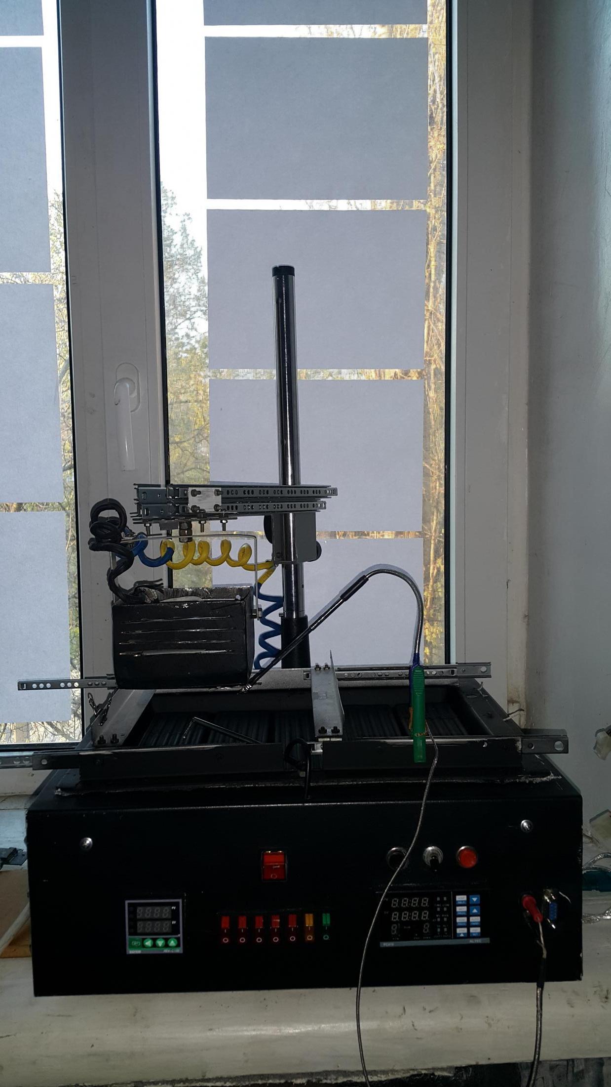
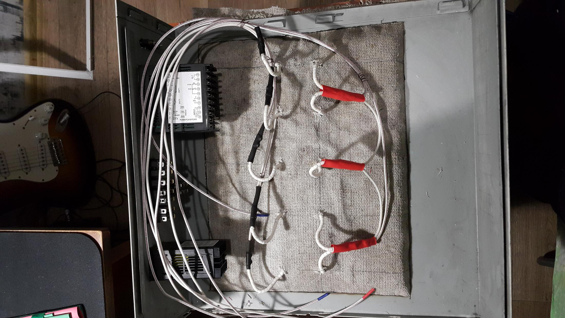
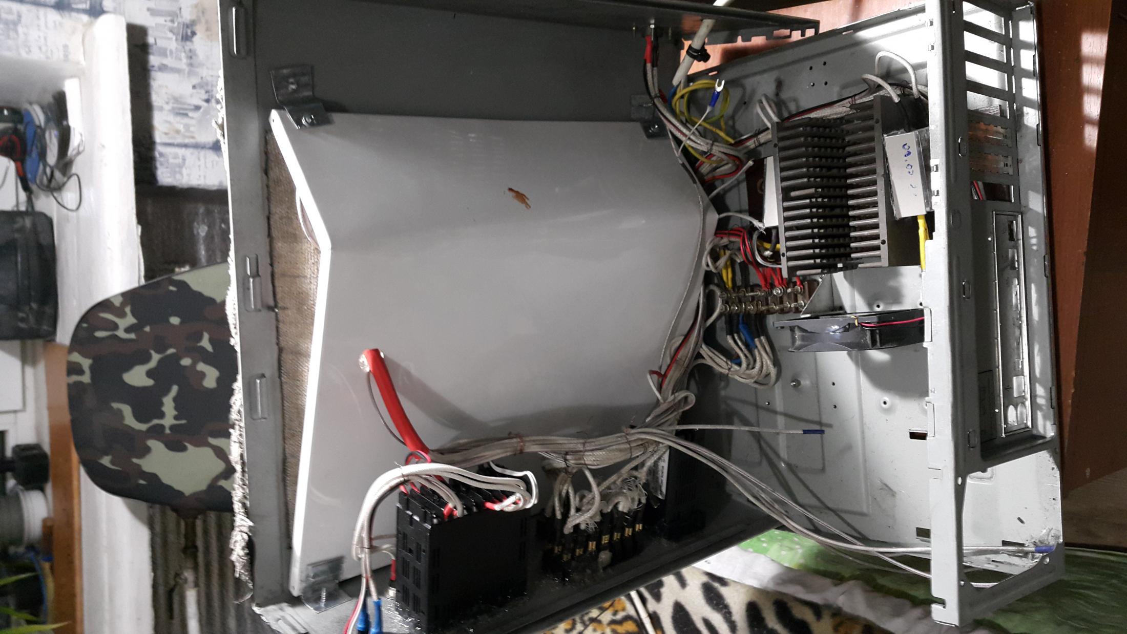
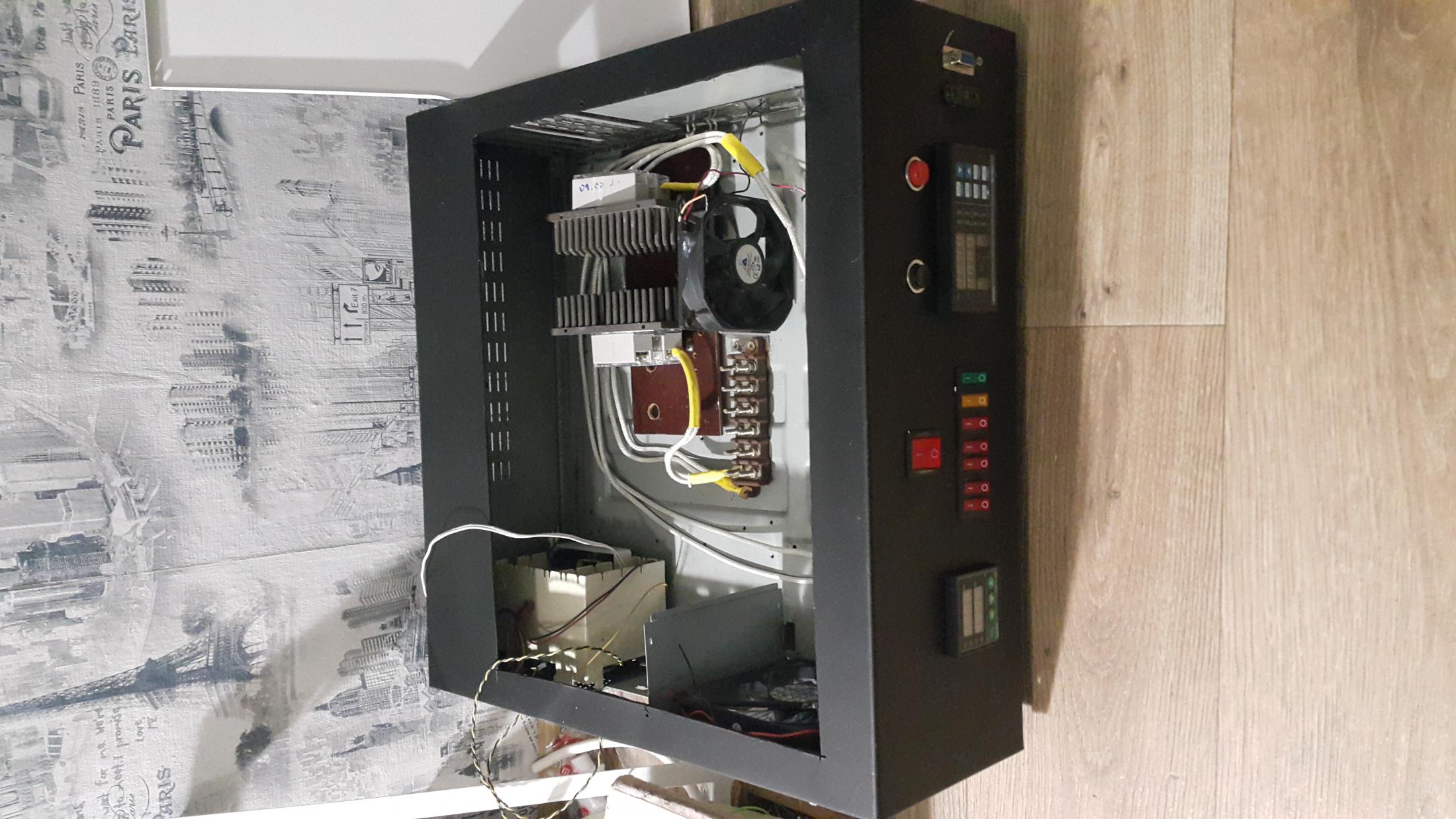
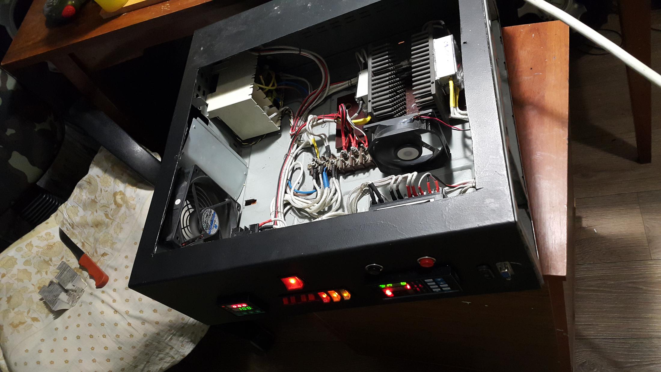
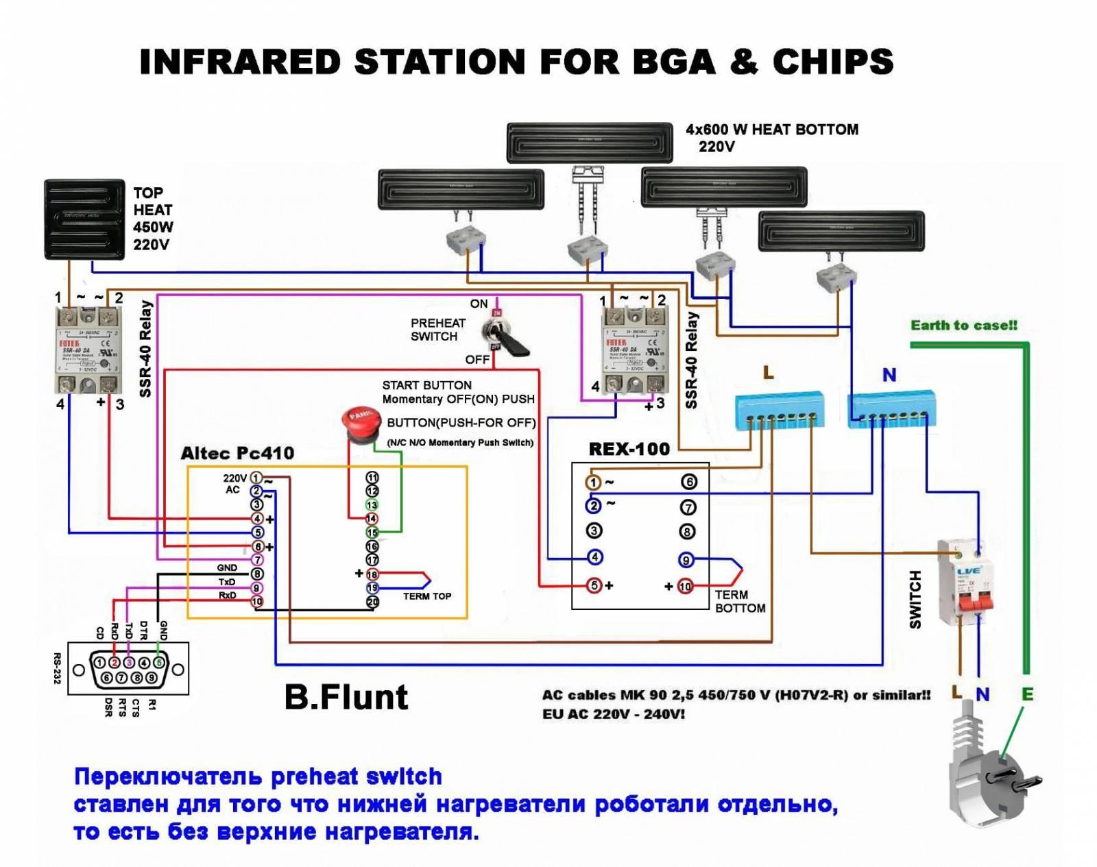
Собирал в корпусе от ПК, что-то заказывал в интернете что-то на рынке, схема довольно проста.
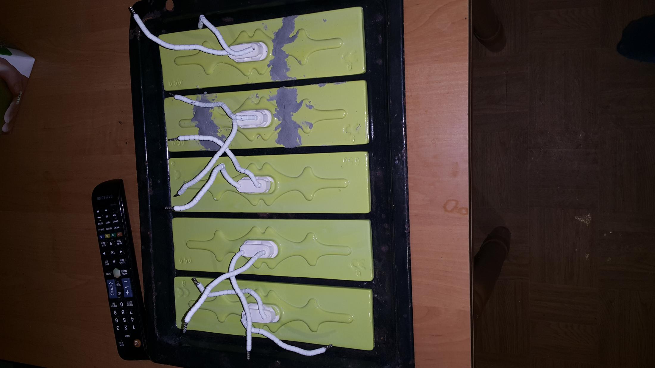
Внутренний монтаж был выполнен термостойким проводом сечением 1.5 РКГМ. Корпус от древнего системного блока ,так как толщина металла довольно хорошая. Нижний подогрев Турецкие ТЭН 600Вт. Сделал на пять штук, каждый включается отдельно.
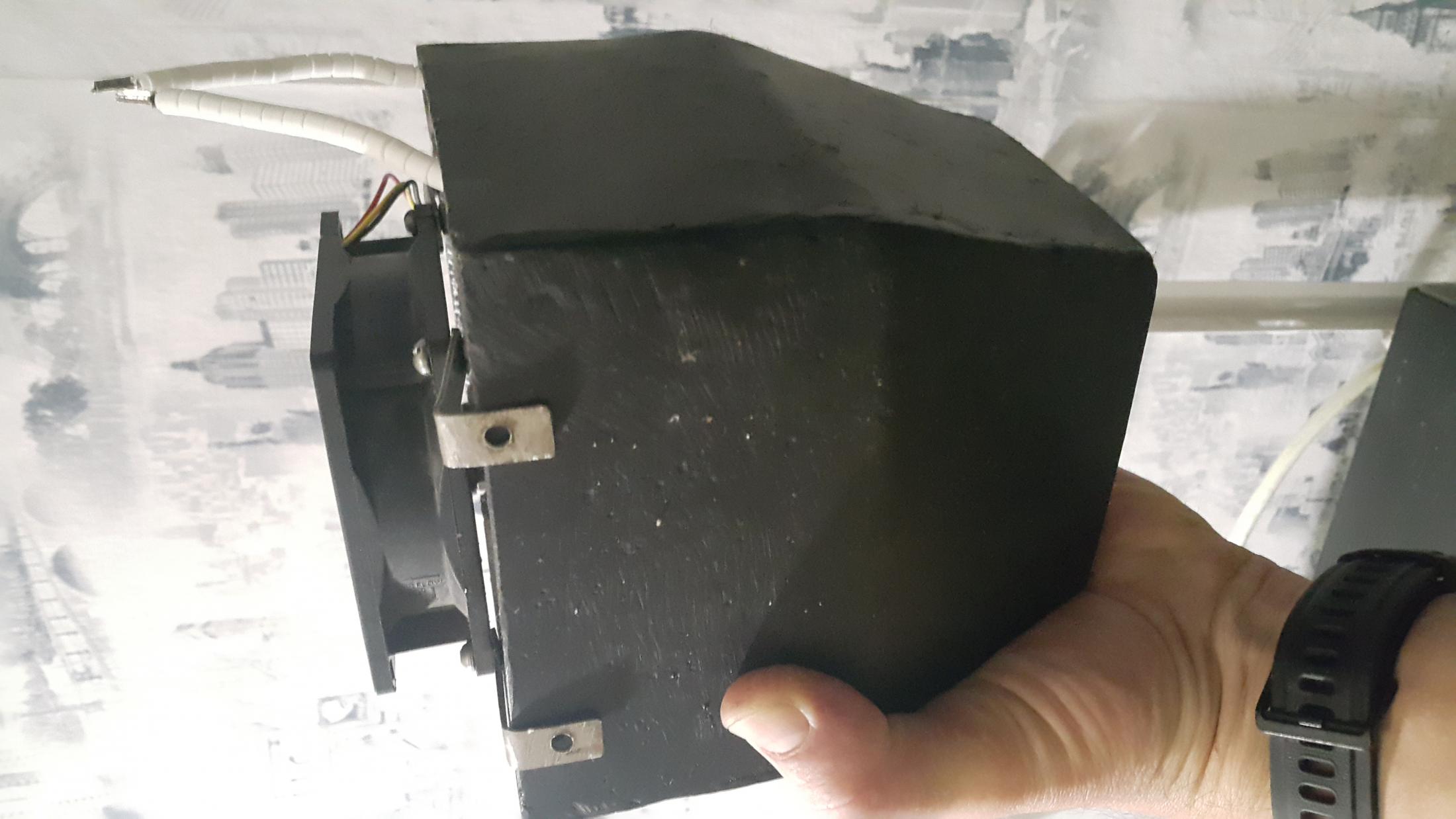
Верхний подогрев Керамический 650 Вт. Верхний кожух варился из металла, но был доработан, срезан.
В качестве верхнего держателя в интернете был заказан фотоувеличитель.
Два ТЭНа пришли треснутые, были восстановлены автомобильной пастой для ремонта глушителей ,прожарены в духовке. В качестве основания был взят протвень от духовки
Низ защищен асбестовой тканью.
Также установлен защитный кожух от перегрева внутри прибора.
Блок питания для кулеров 12в вмонтирован в пластмассовый корпус с охлаждением, взят от приставки т2.
Установлены дополнительные кулеры для лучшего охлаждения.
Контроллеры REX-C100 (Терморегулятор) и Altec PC410 (PID-контроллер) куплены на Aliexpress. Кнопки пуск, стоп, кнопки включения выключения тэнов.


Я собрал
0
0
x
Оценить статью
- Техническая грамотность
- Актуальность материала
- Изложение материала
- Полезность устройства
- Повторяемость устройства
- Орфография
0
Средний балл статьи: 0
Проголосовало: 0 чел.
►
Программатор РС-410 , Можно к муфелю подключить?
|
v-3
Пользователь Сообщений: 19 |
Добавлено: 02.03.2020 14:21:25 Кто нибудь владеет информацией по программатору РС-410? Можно ли его к муфелю подключить? Видел информацию, что в настройках можно установить макс. температуру 1300. Но в инструкции до 400. Изменено: |
|
|
|
Olorin
Пользователь
Сообщений: 667 |
Добавлено: 02.03.2020 14:32:37 v-3, За ваш терморегулятор не скажу, не сталкивался, надо подробно читать инструкцию. Olorin |
|
|
|
огреС
Пользователь Сообщений: 3273 |
Добавлено: 02.03.2020 14:38:55
рисуют и до +1820 °C… а там кто его знает… Изменено: |
||||
|
Offline ЛС |
|
|
Olorin
Пользователь
Сообщений: 667 |
Добавлено: 02.03.2020 14:41:13 огреС, Olorin |
|
|
|
Olorin
Пользователь
Сообщений: 667 |
Добавлено: 02.03.2020 14:43:59 Всё верно, по ссылке пишут Термодатчики и область температур ( выбирается программированием ) термопары: (K, J, R, S, B, E, N, T ) тип К (ТХА) (хромель-алюмель, чувствительность 41 мкВ/°C) 0 — +1370 °C Olorin |
|
|
|
v-3
Пользователь Сообщений: 19 |
Добавлено: 02.03.2020 14:48:29
Да у меня тип К. Подключил, настроил, не работает. Вот и ищу того, кто уже работает, может в настройках где-то не прав. Изменено: |
||||
|
Offline ЛС |
|
|
v-3
Пользователь Сообщений: 19 |
Добавлено: 02.03.2020 14:52:06 Вот тоже мучился товарищ и плюнул https://mysku.me/blog/china-stores/60759.html
https://mysku.me/blog/china-stores/60759.html#
0 https://mysku.me/blog/china-stores/60759.html#
Если китайский клон, то это полное г… У меня на высоких температурах так и не заработал. Пришлось отдать денег отечественному производителю. Хотя, может мне какая-то глючная версия прибора попалась. |
||||
|
Offline ЛС |
|
|
Olorin
Пользователь
Сообщений: 667 |
Добавлено: 02.03.2020 16:13:54
от того что вы сделали до заработал — дистанция огромного размера. Тогда — работает и подключили правильно. Olorin |
||||
|
Offline ЛС |
|
|
v-3
Пользователь Сообщений: 19 |
Добавлено: 02.03.2020 17:00:04 Olorin, |
|
|
|
v-3
Пользователь Сообщений: 19 |
Добавлено: 02.03.2020 18:28:00 Спасибо, друзья! Кажется разобрался. Нужно было замкнуть 2 контакта на программаторе. |
|
|
|
uvrigel
Пользователь Сообщений: 2175 |
Добавлено: 03.03.2020 11:30:14 v-3, |
|
|
|
v-3
Пользователь Сообщений: 19 |
Добавлено: 03.03.2020 11:52:21 uvrigel, |
|
|
Попробую немного помочь новичкам, надеюсь не наврежу)
C этими китаянками только опытным путем можно работать, главное понять суть!
Первым делом нужно откалибровать станцию, для этого установить (!ненужную!) плату как положено, с термопарой и верхом. Затем удерживаем кнопку ParSet несколько секунд — войдем меню, этой же кнопкой выбираем параметр Tune и стрелочкой ставим On, снова щелкаем Parset пока не пролистаются все параметры. После этого включится режим автонастройки, верх будет нещадно жарить плату, так что ей придет конец, но станция будет работать поточнее.
После калибровки можно уж и термопрофилем заняться. Суть проста как три рубля: каждый шаг состоит из трех пунктов: r, l, d, где r — скорость нагрева, l — температура d — задержка. Пид будет стараться выходить на заданную температуру d со скоростью r и удержить эту температуру d секунд.
Далее следует учесть, что скорость нагрева китайских нагревателей оставляет желать лучщего, поэтому на первом шаге неплохо создать задержку в несколько минут, дабы низ успел разогреть плату до 150 градусов. Естественно предварительно опытным путем установить сколько градусов требуется задать низу, чтобы разогреть плату до 150, у меня 270, но это эльштайн, на родном было 280. Кстати нижнюю термопару я ставлю непосредственно на нижний нагреватель, иначе он меряет непонятно что. На втором шаге желательно дать уже разогреться верху, если этого не сделать, то будет отставание от термопрофиля градусов в 20, придется продлевать время пайки, а это уже не есть гуд. Ну и на следующем шаге непосредственно приступаем к пайке, температуру пайки лучше тоже устанавливать опытным путем, у меня на 218-220 паяет безсвинец. При большом желании можно сделать промежуточные шаги, но я не вижу смысла заморачиваться, когда работает и так. В заключении приведу свои профили, которыми пользовался на родных нагревателях.
r1 1 l1 30 d1 350
r2 2 l2 170 d2 30
r3 1 l3 220 d3 30
низ 280
Пробуйте, экперементируйте, желаю удачи!

