- Manuals
- Brands
- Perkins Manuals
- Engine
- 1104
Manuals and User Guides for Perkins 1104. We have 5 Perkins 1104 manuals available for free PDF download: Disassembly And Assembly, Operation And Maintenance Manual, Workshop Manual
Section 2 • Specifications
SPECIFICATIONS
GTH-636, GTH-644, GTH-842 and GTH-844
Displacement
Number of cylinders
Bore and stroke
Horsepower
Firing order
Compression ratio
Low idle
Frequency
High idle
Frequency
Valve clearance, cold
Intake
Exhaust
Lubrication system
Oil pressure at high idle, minimum
Oil capacity
(including filter)
Oil viscosity requirements
Units ship with 15W-40.
Extreme operating temperatures may require the use of
alternative engine oils. For oil requirements, refer to the
Engine Operation and Maintenance Manual on your
machine.
2 — 10
GTH-636 • GTH-644 • GTH-842 • GTH-844 • GTH-1048 • GTH-1056
269 cu in
4.4 liters
4
4.133 x 5 inches
105 x 127 mm
99.9 @ 2500 rpm
74.5 kW @ 2500 rpm
1 — 3 — 4 — 2
18.2:1
1000 rpm
200 Hz
2520 rpm
504 Hz
0.008 in
0.2 mm
0.018 in
0.45 mm
43 psi
3 bar
7 quarts
6.5 liters
Injection system
Injection pump make
Injector pressure, minimum
Lift pump pressure
Fuel requirement
For fuel requirements, refer to the engine Operation
Manual on your machine.
Engine coolant
Capacity
Alternator
Output
Fan belt tension (new belt / used belt)
Battery
Type
Group
Quantity
Cold cranking ampere @ 0°F
Reserve capacity @ 25A rate
Continuous improvement of our products is a
Genie policy. Product specifications are
subject to change without notice.
June 2007
REV D
Delphi
4380 psi
302 bar
4.5 to 9.5 psi
0.31 to 0.66 bar
4.75 gallons
18 liters
85 A, 14V DC
120 / 80 lbf
535 / 355 N
12V DC
C31
1
1000A
200 minutes
Part No. 97487
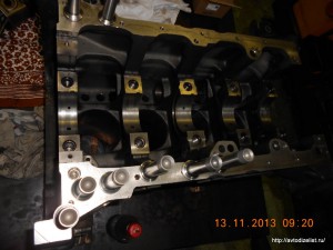
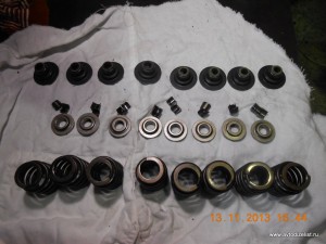
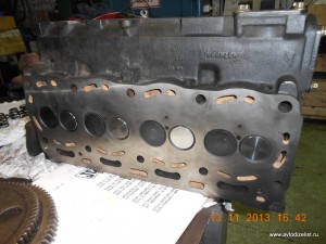
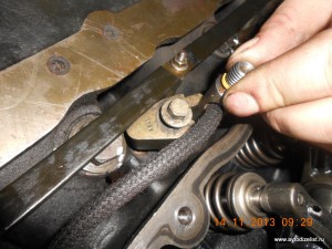
Фотоотчет о сборке PERKINS 1104С-44Т RG81374
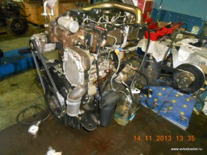
Одна из самых распространенных моделей двигателя PERKINS серии 1104. Этот тип моторов можно повстречать на экскаваторах и погрузчиках, таких как VINIERI, TEREX, JCB, JON DEER, MANITOU, ТВЭКС.
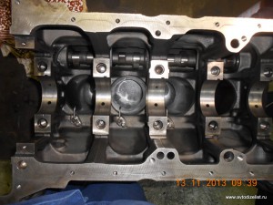
Начнем с того, что мотор разобран, отдефектован, отмыт.
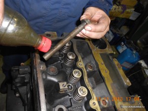
Смазываем и устанавливаем толкатели клапанов.
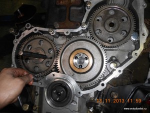
Ставим распредвал.
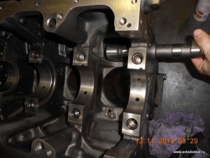
Монтируем маслофорсунки.
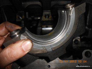
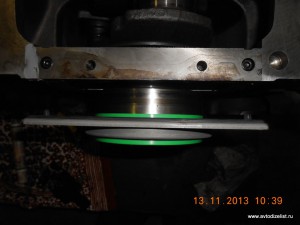
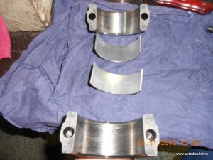
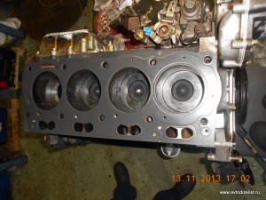
Еще раз чистим, протираем постель коленвала и устанавливаем коренные вкладыши. Мажем маслом вкладыши, укладываем коленчатый вал в блок.
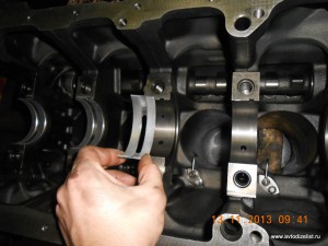
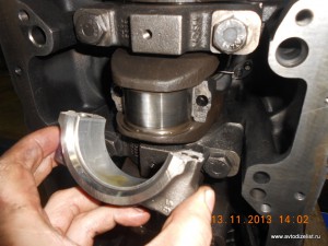
Не забываем смазывать и ставить верхние упорные полукольца проточками к коленвалу.
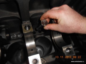
Ставим нижние коренные вкладыши в крышки коренных подшипников, мажем маслом, ставим крышки строго на свои места замок к замку. Важно не перепутать первую и пятую крышку.
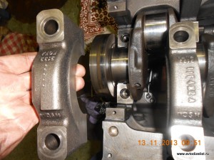
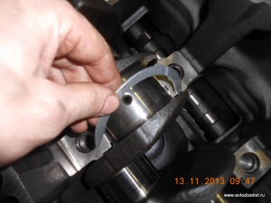
Пятая крышка имеет характерный прилив.
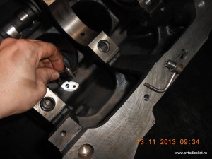
В третью крышку вкладываем пару нижних упорных полуколец и ставим в блок.
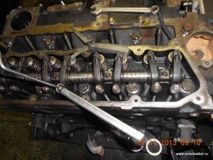
Смазываем крепежные болты чистым моторным маслом по резьбе и под шляпкой, закручиваем согласно карте моментов затяжки.
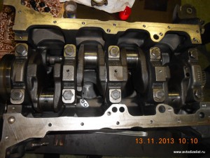
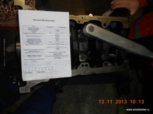
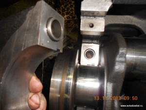
Проверяем плавность и легкость вращения коленчатого вала после притяжки каждого бугеля, начинаем от центра.
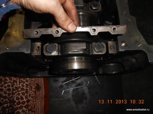
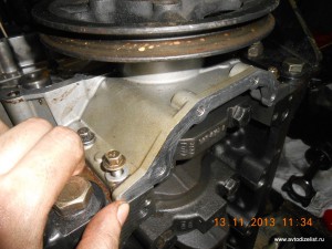
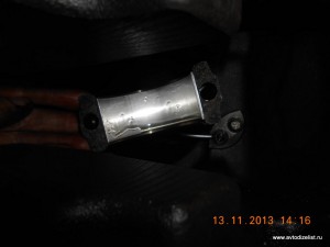
Над пятым бугелем крепим планку – нижнюю опору заднего сальника коленвала.
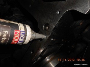
Заполняем герметиком полость стыковки.
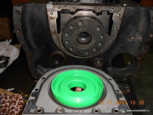
Монтируем витоновый сальник.
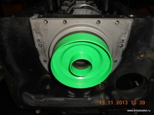
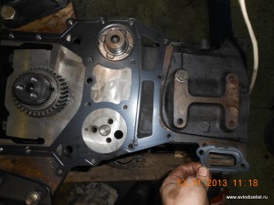
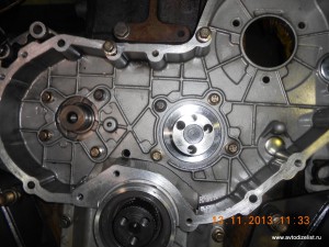
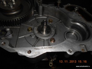
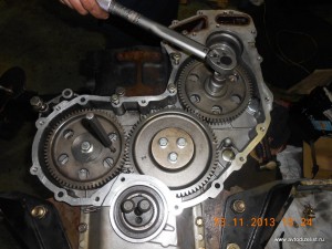
Далее переворачиваем блок передней частью вверх, монтируем корпус блока шестерен.
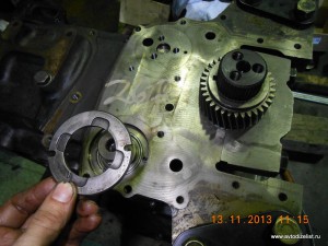
Ось паразитной шестерни ставим так, чтобы совпали масляные каналы.
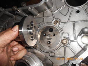
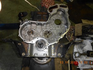
Одеваем на коленвал передний шкив, центрируем корпус шестерен по сальнику. Затем затягиваем крепеж корпуса шестерен.
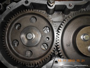
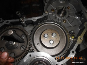
Одеваем шестерню распредвала, выставляем вал по штифту. Положение соответствует ВМТ такта сжатия в первом цилиндре.
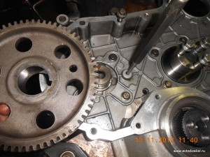
Выставляем коленвал в положение ВМТ первого цилиндра, фиксируем вторым штифтом. Устанавливаем паразитную шестерню, проверяем положения валов по штифтам.
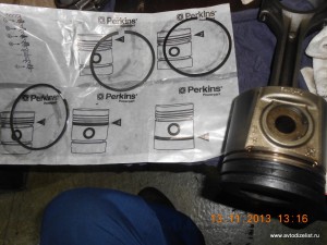
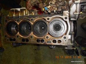
Одеваем поршневые кольца согласно инструкции.
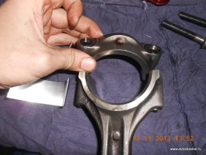
Укладываем беззамковые шатунные вкладыши в свои места.
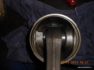
Следует отметить, что поршни имеют угловатый прилив, который ориентирован в переднюю часть мотора. Шатун имеет выпуклый прилив, он тоже должен быть направлен к переду мотора.
Крышка шатуна тоже отмечена приливом.
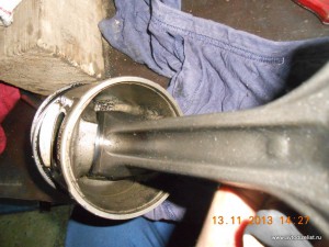
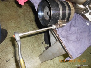
Оправкой стягиваем поршневые кольца.
Устанавливаем поршни с шатунами в цилиндры, важно проконтролировать движение шатуна на выходе из цилиндра, чтобы не сломать носик масляной форсунки.
Закрываем крышки шатунов, затягиваем согласно карты моментов, проверяем плавность и легкость вращения шатунных подшипников.
Произведем монтаж ТНВД. Коленвал с распредвалом зафиксированы штифтами. Вал ТНВД должен быть неподвижно зажат фиксирующим болтом.
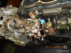
Затягиваем крепеж ТНВД, притягиваем шестерню соответствующим моментом. Вынимаем штифты, распускаем стопор вала ТНВД. Закрываем переднюю крышку, крепим помпу.
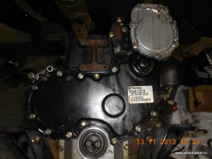
Монтируем маслонасос, закрываем масляный поддон, переворачиваем мотор в нормальное положение.
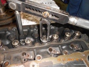
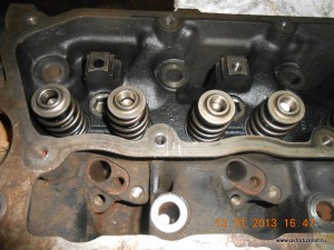
Собираем ГБЦ.
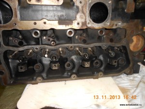
Кладем прокладку и монтируем ГБЦ.
Устанавливаем штанги, ось коромысел. Регулируем тепловой зазор клапанов.
Монтируем свечи накала, топливные форсунки.
Прикручиваем навесное оборудование.
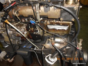
Подсоединяем топливопроводы, запитываем насосы, крутим стартером. Меряем давление масла в системе, прокачиваем топливную аппаратуру, делаем первый запуск.
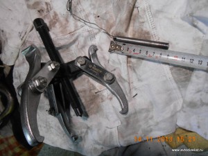
Специнструменты для демонтажа ТНВД.
Mr Gluhov
![]()
Perkins 1104 Series
WORKSHOP MANUAL
Troubleshooting
4 cylinder, naturally aspirated, and turbocharged diesel engines for agricultural and industrial use
Publication RENR2696-00
© Proprietary information of Perkins Engines Company Limited 2004, all rights reserved. The information is correct at the time of print.
Published by Technical Publications.
Perkins Engines Company Limited, Peterborough, PE1 5NA, England

3 Table of Contents
|
Table of Contents |
|
|
Troubleshooting Section |
|
|
Electronic Troubleshooting |
|
|
System Overview ……………………………………………. |
5 |
|
Glossary ……………………………………………………….. |
9 |
|
Electronic Service Tools …………………………………. |
12 |
|
Diagnostic Codes ………………………………………….. |
13 |
|
Indicator Lamps ……………………………………………. |
15 |
|
Replacing the ECM ……………………………………….. |
18 |
|
Self-Diagnostics ……………………………………………. |
19 |
|
Sensors and Electrical Connectors ………………….. |
20 |
|
Engine Wiring Information ……………………………… |
26 |
|
Programming Parameters |
|
|
Programming Parameters ………………………………. |
30 |
|
Factory Passwords ………………………………………… |
30 |
|
Flash Programming ………………………………………. |
30 |
|
System Configuration Parameters |
|
|
System Configuration Parameters …………………… |
32 |
|
Troubleshooting without a Diagnostic Code |
|
|
Alternator Noise (Noisy Operation) ………………….. |
33 |
|
Alternator Will Not Charge (Charging Problem) …. |
33 |
|
Battery ………………………………………………………… |
33 |
|
Can Not Reach Top Engine RPM ……………………. |
34 |
|
Coolant in Engine Oil …………………………………….. |
36 |
|
Coolant Temperature Is Too High ……………………. |
37 |
|
ECM Will Not Accept Factory Passwords …………. |
38 |
|
ECM Will Not Communicate with Other Systems or |
|
|
Display Modules ………………………………………….. |
38 |
|
Electronic Service Tool Will Not Communicate with |
|
|
ECM ………………………………………………………….. |
38 |
|
Engine Cranks but Will Not Start …………………….. |
39 |
|
Engine Has Early Wear …………………………………. |
41 |
|
Engine Misfires, Runs Rough or Is Unstable …….. |
41 |
|
Engine Oil in Cooling System …………………………. |
43 |
|
Engine Speed Does Not Change …………………….. |
44 |
|
Engine Stalls at Low RPM ……………………………… |
45 |
|
Engine Vibration …………………………………………… |
45 |
|
Engine Will Not Crank ……………………………………. |
47 |
|
Excessive Black Smoke …………………………………. |
48 |
|
Excessive Engine Oil Consumption …………………. |
49 |
|
Excessive Valve Lash ……………………………………. |
50 |
|
Excessive White Smoke ………………………………… |
51 |
|
Intake Air Temperature Is Too High ………………….. |
52 |
|
Intermittent Engine Shutdown …………………………. |
53 |
|
Intermittent Low Power or Power Cutout …………… |
54 |
|
Low Engine Oil Pressure ……………………………….. |
56 |
|
Low Power/Poor or No Response to Throttle …….. |
57 |
|
Mechanical Noise (Knock) in Engine ……………….. |
59 |
|
Noise Coming from Cylinder …………………………… |
59 |
|
Poor Acceleration or Response ………………………. |
60 |
|
Troubleshooting with a Diagnostic Code |
|
|
CID 0041 FMI 03 8v Sensor Power Supply, Voltage |
|
|
More Than Normal ………………………………………. |
62 |
|
CID 0041 FMI 04 8v Sensor Power Supply, Voltage |
|
|
Less Than Normal ……………………………………….. |
62 |
|
CID 0091 FMI 02 Throttle Demand Sensor Erratic Or |
|
|
Intermittent …………………………………………………. |
62 |
|
CID 0091 FMI 03 Throttle Demand Sensor Open |
|
|
Circuit Or Shorted High ………………………………… |
63 |
|
CID 0091 FMI 04 Throttle Demand Sensor Shorted |
|
|
Low …………………………………………………………… |
63 |
|
CID 0091 FMI 08 Throttle Demand Sensor Abnormal |
|
|
Signal ………………………………………………………… |
64 |
|
CID 0091 FMI 12 Throttle Demand Sensor Out Of |
|
|
Calibration ………………………………………………….. |
64 |
|
CID 0100 FMI 03 Engine Oil Pressure Sensor Open |
|
|
Circuit Or Shorted High ………………………………… |
64 |
|
CID 0100 FMI 04 Engine Oil Pressure Sensor |
|
|
Shorted Low ……………………………………………….. |
65 |
|
CID 0100 FMI 10 Engine Oil Pressure Sensor, Power |
|
|
Supply Open Circuit …………………………………….. |
65 |
|
CID 0102 FMI 03 Intake Manifold Pressure Sensor, |
|
|
Open Circuit Or Shorted High ……………………….. |
66 |
|
CID 0102 FMI 04 Intake Manifold Pressure Sensor |
|
|
Shorted Low ……………………………………………….. |
66 |
|
CID 0102 FMI 10 Intake Manifold Pressure Sensor |
|
|
Power Supply Open Circuit …………………………… |
67 |
|
CID 0105 FMI 03 Intake Manifold Temperature |
|
|
Sensor Open Circuit Or Shorted High ……………. |
67 |
|
CID 0105 FMI 04 Intake Manifold Temperature |
|
|
Sensor Shorted Low ……………………………………. |
67 |
|
CID 0110 FMI 03 Engine Coolant Temperature |
|
|
Sensor Open Circuit Or Shorted High ……………. |
68 |
|
CID 0110 FMI 04 Engine Coolant Temperature |
|
|
Sensor Shorted Low ……………………………………. |
68 |
|
CID 0174 FMI 02 Fuel Temperature Sensor Erratic, |
|
|
Intermittent …………………………………………………. |
69 |
|
CID 0247 FMI 09 J1939 Datalink, Abnormal |
|
|
Update ………………………………………………………. |
69 |
|
CID 0253 FMI 02 Incorrect ECM Software ……….. |
69 |
|
CID 0262 FMI 03 5v Sensor Power Supply, Voltage |
|
|
More Than Normal ………………………………………. |
70 |
|
CID 0262 FMI 04 5v Sensor Power Supply, Voltage |
|
|
Less Than Normal ……………………………………….. |
70 |
|
CID 0266 FMI 02 Incorrect Crank-without-inject |
|
|
inputs ………………………………………………………… |
71 |
|
CID 0320 FMI 02 Speed And Timing Sensor |
|
|
Intermittent Loss Of Signal ……………………………. |
71 |
|
CID 0320 FMI 11 Speed And Timing Sensor Loss Of |
|
|
Signal ………………………………………………………… |
71 |
|
CID 0342 FMI 02 Speed And Timing Sensor No.2 |
|
|
Intermittent Signal ……………………………………….. |
72 |
|
CID 0774 FMI 02 Throttle Demand Sensor No.2 |
|
|
Erratic Or Intermittent …………………………………… |
72 |
|
CID 0774 FMI 03 Throttle Demand Sensor No.2 |
|
|
Open Circuit Or Shorted High ……………………….. |
73 |
|
CID 0774 FMI 04 Throttle Demand Sensor No.2 |
|
|
Shorted Low ……………………………………………….. |
73 |
|
CID 0774 FMI 08 Throttle Demand Sensor No.2 |
|
|
Abnormal Signal ………………………………………….. |
73 |
|
CID 0774 FMI 12 Throttle Demand Sensor No.2 Out |
|
|
Of Calibration ……………………………………………… |
74 |
|
CID 1627 FMI 03 Fuel Injection Pump Relay Did Not |
|
|
Turn Off ……………………………………………………… |
74 |
|
CID 1684 FMI 00 Fuel Injection Pump, Fuel |
|
|
Temperature More Than Normal ……………………. |
74 |
|
CID 1684 FMI 02 Fuel Injection Pump, Software |
|
|
Failure ……………………………………………………….. |
75 |

|
CID 1684 FMI 03 Fuel Injection Pump, Fuelling |
||
|
Fault ………………………………………………………….. |
75 |
|
|
CID 1684 FMI 04 Fuel Injection Pump, Supply |
||
|
Voltage Fault ………………………………………………. |
76 |
|
|
CID 1684 FMI 05 Fuel Injection Pump, Invalid Pulse |
||
|
Width …………………………………………………………. |
76 |
|
|
CID 1684 FMI 07 Fuel Injection Pump, Mechanical |
||
|
Fault ………………………………………………………….. |
77 |
|
|
CID 1684 FMI 08 Fuel Injection Pump, Crankshaft |
||
|
Reference Fault …………………………………………… |
77 |
|
|
CID 1684 FMI 09 Fuel Injection Pump, CAN |
||
|
Fault ………………………………………………………….. |
78 |
|
|
CID 1684 FMI 10 Fuel Injection Pump, Fuel Shutoff |
||
|
Signal Error ………………………………………………… |
78 |
|
|
CID 1684 FMI 11 Fuel Injection Pump, Internal |
||
|
Sensor Fault ……………………………………………….. |
79 |
|
|
CID 1684 FMI 12 Fuel Injection Pump, Device |
||
|
Failure ……………………………………………………….. |
80 |
|
|
CID 1684 FMI 14 Fuel Injection Pump, No |
||
|
Communications …………………………………………. |
80 |
|
|
CID 1743 FMI 02 Engine Speed Mode Selection |
||
|
Switch State, Invalid State ……………………………. |
81 |
|
|
CID 1894 FMI 02 Set Speed Control Disengage |
||
|
Switch State, Invalid State ……………………………. |
81 |
|
|
CID 1895 FMI 02 Set Speed Control Speed Toggle |
||
|
Switch, Invalid State …………………………………….. |
81 |
|
|
Troubleshooting with an Event Code |
||
|
Event Codes ……………………………………………….. |
83 |
|
|
E015 |
High Engine Coolant Temperature Derate … |
83 |
|
E016 |
High Engine Coolant Temperature |
|
|
Shutdown …………………………………………………… |
83 |
|
|
E017 |
High Engine Coolant Temperature |
|
|
Warning ……………………………………………………… |
83 |
|
|
E025 |
High Intake Air Temperature Derate ………… |
84 |
|
E027 |
High Intake Air Temperature Warning ……… |
84 |
|
E040 |
Low Engine Oil Pressure Shutdown ………… |
85 |
|
E054 |
High Fuel Temperature Derate ……………….. |
85 |
|
E056 |
High Fuel Temperature Warning ……………… |
86 |
|
E100 |
Low Engine Oil Pressure Warning …………… |
87 |
|
E190 |
Engine Overspeed Warning …………………… |
88 |
|
E442 |
Engine Failed to Stop with a No-Fuel |
|
|
Command ………………………………………………….. |
88 |
|
|
E883 |
Engine Failed To Stop When Fuel Solenoid |
|
|
Disengaged ………………………………………………… |
89 |
|
|
Diagnostic Functional Tests |
||
|
5 Volt Engine Pressure Sensor Supply Circuit — |
||
|
Test |
…………………………………………………………… |
90 |
|
Air Inlet Heater Circuit — Test …………………………… |
97 |
|
|
Analog Throttle Position Sensor Circuit — Test …. |
102 |
|
|
CAN Data Link Circuit — Test …………………………. |
111 |
|
|
Data Link Circuit — Test …………………………………. |
116 |
|
|
Digital Throttle Position Sensor Circuit — Test …… |
124 |
|
|
Electrical Connectors — Inspect ……………………… |
133 |
|
|
Electrical Power Supply Circuit — Test …………….. |
144 |
|
|
Engine Oil Level Switch Circuit — Test …………….. |
149 |
|
|
Engine Pressure Sensor Open or Short Circuit — |
||
|
Test |
…………………………………………………………. |
154 |
|
Engine Speed/Timing Sensor Circuit — Test …….. |
161 |
|
Engine Temperature Sensor Open or Short Circuit — |
|
|
Test …………………………………………………………. |
168 |
|
Fuel Injection Pump Circuit — Test ………………….. |
175 |
|
Indicator Lamp Circuit — Test …………………………. |
192 |
|
Mode Selection Circuit — Test ………………………… |
195 |
|
Set Speed Circuit — Test ……………………………….. |
202 |
|
Throttle Switch Circuit — Test …………………………. |
210 |
|
Index Section |
|
|
Index …………………………………………………………. |
219 |

5 Troubleshooting Section
Troubleshooting Section
Electronic Troubleshooting
i01798100
System Overview
System Operation
The 1104 models RF, RH, RK and 1106 model VK engines were designed for electronic control. The engines include an Electronic Control Module (ECM), a fuel injection pump that is electronically controlled, and a collection of engine sensors. The ECM controls the engine operating parameters
through the software within the ECM and the inputs from the various sensors. The software contains parameters that control the engine operation. The parameters include all of the operating maps and customer selected parameters.

6
Troubleshooting Section
Electronic Controls

7 Troubleshooting Section
Illustration 2
The electronic system consists of the Electronic Control Module (ECM), the engine sensors, and the Machine Interface Connector (MIC). The ECM is the computer. The personality module is the software for the computer. The personality module contains the operating maps. The operating maps define the following characteristics of the engine:
•Horsepower
•Torque curves
•Engine speed (rpm)
Engine Governor
The electronic controls determine the injection timing and the amount of fuel that is delivered to the cylinders. These decisions are based on the actual conditions and the desired conditions at any given time.
g00954204
The governor compares the desired engine speed to the actual engine speed. The actual engine speed is determined through the crankshaft position sensor. If the desired engine speed is greater than the actual engine speed, the governor injects more fuel in order to increase engine speed.
Timing Considerations
Once the governor has determined the amount of fuel that is required, the governor must determine the timing of the fuel injection. Fuel injection timing is determined by the ECM after considering input from the following components:
•Engine coolant temperature sensor
•The sensor for the intake manifold air temperature
•The sensor for the intake manifold pressure

8
Troubleshooting Section
At start-up, the ECM determines the top dead center position of the number 1 cylinder from the speed/timing sensor in the fuel injection pump. The ECM decides when fuel injection should occur relative to the top dead center position. The ECM provides the signal to the fuel injection pump spill valve which stops fuel flow to the low pressure side. The ECM then forces fuel to flow to the fuel injector nozzles at the desired time. The ECM adjusts timing for the best engine performance, the best fuel economy and the best control of exhaust emissions. Actual timing cannot be viewed with an electronic service tool. Also, the desired timing cannot be viewed with an electronic service tool.
Fuel Injection
The personality module inside the ECM sets certain limits on the amount of fuel that can be injected. The FRC Limit is a limit that is based on intake manifold air pressure and engine rpm. The FRC Limit is used to control the air/fuel ratio in order to control the engine’s exhaust emissions. When the ECM senses a higher intake manifold air pressure, the ECM increases the FRC Limit. A higher intake manifold air pressure indicates that there is more air in the cylinder. When the ECM increases the FRC Limit, the ECM allows more fuel into the cylinder.
The Rated Fuel Limit is a limit that is based on the power rating of the engine and on the engine rpm. The Rated Fuel Limit enables the engine power and torque outputs to conform to the power and torque curves of a specific engine model.
These limits are in the personality module and these limits cannot be changed.
Diagnostic Codes
When the ECM detects an engine problem, the ECM generates a diagnostic code. Also, the ECM logs the diagnostic code in order to indicate the time of the problem’s occurrence. The ECM also logs the number of occurrences of the problem. There are two types of diagnostic fault codes. There are fault codes and event codes.
Diagnostic Fault Codes
Diagnostic fault codes are provided in order to indicate that an electrical problem or an electronic problem has been detected by the ECM. In some cases, the engine performance can be affected when the condition that is causing the code exists. More frequently, the operator cannot detect any difference in the engine performance.
If the operator indicates that a performance problem occurs, the diagnostic code may indicate the cause of the problem. Use either a laptop computer or a hand held diagnostic tool to access the diagnostic codes. The problem should then be corrected.
If the operator does not indicate a problem with the engine performance and a diagnostic code is logged by the ECM. This situation indicates that the ECM detected an abnormal engine condition, but the abnormal condition did not affect engine performance. In this situation, the system has no faults except when either of the following conditions exist:
•There are several occurrences of the diagnostic code in a very short period of time.
•The ECM is indicating an active code at the present time.
Diagnostic Event Codes
Diagnostic event codes are used to indicate that some operational problem has been detected in the engine by the ECM. This does not indicate an electronic malfunction.
Programmable Parameters
Certain parameters that affect the engine operation may be changed with electronic service tools. The parameters are stored in the ECM, and the parameters are protected from unauthorized changes by passwords. These parameters are System Configuration Parameters.
System Configuration Parameters are set at the factory. System Configuration Parameters affect emissions or power ratings within the engine.
Factory passwords must be obtained and factory passwords must be used to change the System Configuration Parameters.
Passwords
System Configuration Parameters are protected by factory passwords. Factory passwords are calculated on a computer system that is available
only to Perkins distributors. Since factory passwords contain alphabetic characters, only an electronic service tool may change System Configuration Parameters. System Configuration Parameters affect the power rating or the emissions.
Refer to Troubleshooting, “Programming Parameters” and Troubleshooting, “Factory Passwords”.

9 Troubleshooting Section
i01798101
Glossary
Active Diagnostic Code – An active diagnostic code alerts the operator or the service technician that an electronic system malfunction is currently present.
Refer to the term “Diagnostic Code” in this glossary.
Alternating Current (AC) – Alternating current is an electric current that reverses direction at a regular interval that is reoccurring.
Before Top Dead Center (BTC) – BTDC is the 180 degrees of crankshaft rotation before the piston reaches the top dead center position in the normal direction of rotation.
Boost Pressure (Engines that are turbocharged) –
The difference between the turbocharger outlet pressure and atmospheric pressure is commonly referred to as boost pressure. The sensor for the intake manifold air pressure measures the amount of boost.
Breakout Harness – The breakout harness is a test harness that is designed to connect into the engine harness. This connection allows a normal circuit operation and the connection simultaneously provides a Breakout T in order to measure the signals.
Bypass Circuit – A bypass circuit is a circuit that is used as a substitute circuit for an existing circuit. A bypass circuit is typically used as a test circuit.
CAN Data Link – The CAN Data Link is a serial communications port that is used for communication with other microprocessor based devices. In this application, the CAN Data Link connects the ECM to the Electronic Fuel Injection Pump.
Code – Refer to “Diagnostic Code” or “Event Code”.
Cold Mode – Cold mode is a mode for cold starting and for cold engine operation that includes timing that is retarded and low idle that is raised. This mode is used for engine protection, reduced smoke emissions and faster warm up time.
Communication Adapter Tool – The communication adapter provides a communication link between the ECM and the Electronic Service Tool.
Component Identifier (CID) – The CID is a number that identifies the specific component of the electronic control system that has experienced a diagnostic code.
Coolant Level Sensor – The coolant level sensor detects the absence or presence of coolant at the probe. The sensor then sends a signal to the ECM.
Coolant Temperature Sensor – The coolant temperature sensor detects the engine coolant temperature for cold mode operation and for Engine Monitoring.
Data Link – The Data Link is a serial communication port that is used for communication with other microprocessor based devices.
Desired Engine Speed – The desired engine speed is input to the electronic governor within the ECM. The electronic governor uses the signal from the throttle position sensor, the engine speed/timing sensor, and other sensors in order to determine the desired engine speed.
Diagnostic Code – A diagnostic code is sometimes referred to as a fault code. These codes indicate an electronic system malfunction.
Diagnostic Lamp – A diagnostic lamp is sometimes called the check engine light. The diagnostic lamp is used to warn the operator of the presence of an active diagnostic code.
Digital Sensor Return – The common line (ground) from the ECM is used as ground for the digital sensors.
Digital Sensors – Digital sensors produce a pulse width modulated signal. Digital sensors are supplied with +8 VDC from the ECM.
Digital Sensor Supply – The +8 VDC supply from the ECM is used in order to power the digital sensors.
Direct Current (DC) – Direct current is the type of current that flows consistently in only one direction.
DT, DT Connector, or Deutsch DT – This is a type of connector that is used on Perkins engines. The connectors are manufactured by Deutsch.
Duty Cycle – Refer to “Pulse Width Modulation”.
Electronic Engine Control – The electronic engine control is a complete electronic system. The electronic engine control monitors the engine operation under all conditions. The electronic engine control also controls the engine operation under all conditions.
Electronic Service Tool – The electronic service tool allows a computer (PC) to communicate with the ECM.

10
Troubleshooting Section
Electronic Control Module (ECM) – The ECM is the control computer of the engine. The ECM provides power to the electronics. The ECM monitors data that is input from the sensors of the engine. The ECM acts as a governor in order to control the speed and the power of the engine.
Engine Monitoring – Engine Monitoring is the part of the electronic engine control that monitors the sensors. This also warns the operator of detected problems.
Engine Oil Pressure Sensor – The engine oil pressure sensor measures engine oil pressure. The sensor sends the signal to the ECM.
Engine Speed/Timing Sensor – The engine speed/timing sensor provides a variable amplitude and pulse width modulated signal to the ECM. The ECM interprets this signal as the crankshaft position and the engine speed.
Event Code – An event code may be activated in order to indicate an abnormal engine operating condition. These codes usually indicate a mechanical problem instead of an electrical system problem.
Failure Mode Identifier (FMI) – This identifier indicates the type of failure that has been experienced by the component. The FMI has been adopted from the SAE practice of J1587 diagnostics.
Flash Programming – Flash programming is the method of programming or updating an ECM with an electronic service tool over the data link instead of replacing components.
Fuel Ratio Control (FRC) – The FRC is a limit that is based on the control of the ratio of the fuel to air. The FRC is used for purposes of emission control. When the ECM senses a higher intake manifold
air pressure (more air into the cylinder), the FRC increases the FRC Limit (more fuel into the cylinder).
Fuel Temperature Sensor – The fuel temperature sensor detects the fuel temperature. The ECM monitors the fuel temperature and the ECM adjusts the calculated fuel rate accordingly.
Full Load Setting (FLS) – The FLS is the number that represents the fuel system adjustment. This adjustment is made at the factory in order to fine tune the fuel system. The correct value for this parameter is stamped on the engine information ratings plate. This parameter must be programmed.
Full Torque Setting (FTS) – The FTS is similar to the full load setting. This parameter must be programmed.
Harness – The harness is the bundle of wiring (loom) that connects all components of the electronic system.
Hertz (Hz) – Hertz is the measure of electrical frequency in cycles per second.
Intake Manifold Air Temperature Sensor – The intake manifold air temperature sensor detects the air temperature in the intake manifold. The ECM monitors the air temperature and other data in the intake manifold in order to adjust injection timing and other performance functions.
Intake Manifold Pressure Sensor – The air pressure in the intake manifold may be different to the
air pressure outside the engine (atmospheric pressure). This difference in air pressure can be caused by variable air velocity within the manifold. The difference in pressure can also be caused by an increase in air pressure by a turbocharger (if equipped). The sensor for the intake manifold air pressure measures the difference between atmospheric pressure and the air pressure in the intake manifold.
Integrated Electronic Controls – The engine is designed with the electronic controls as a necessary part of the system. The engine will not operate without the electronic controls.
J1939 CAN Data Link – This data link is a SAE diagnostic communications data link that is used to communicate between the ECM and the electronic service tool.
Logged Diagnostic Codes – Logged diagnostic codes are codes which are stored in the memory. These codes are meant to be an indicator of possible causes for intermittent problems. Refer to the term “Diagnostic Code” in this glossary for more information.
MAB – This is a Bosch acronym for the fuel shutoff inside the “VPM30” Fuel Injection Pump. The MAB is a signal wire from the ECM to the Fuel Injection Pump.
Open Circuit – An open circuit is a condition that is caused by an open switch, or by an electrical wire or a connection that is broken. When this condition exists, the signal or the supply voltage can no longer reach the intended destination.
Parameter – A parameter is a value or a limit that is programmable. This helps determine specific characteristics or behaviors of the engine.

11 Troubleshooting Section
Password – A password is a group of numeric characters or a group of alphanumeric characters that is designed to restrict access to parameters. The electronic system requires correct passwords in order to change some parameters (Factory Passwords). Refer to Troubleshooting, “Factory Passwords” for more information.
Personality Module – This module is inside the ECM. The module contains all the instructions (software) for the ECM and the module contains the performance maps for a specific engine. The personality module may be reprogrammed through flash programming.
Power Cycled – Power cycled happens when power to the ECM is cycled: ON, OFF, and ON. Power cycled refers to the action of cycling the keyswitch from any position to the OFF position, and to the START/RUN position.
Pulse Width Modulation (PWM) – The PWM is a signal that consists of pulses that are of variable width. These pulses occur at fixed intervals. The ratio of “TIME ON” versus total “TIME OFF” can be varied. This ratio is also referred to as a duty cycle.
Rated Fuel Limit – This term indicates the maximum allowable fuel position (longest injection pulse). This position will produce rated power for this engine configuration.
Reference Voltage – Reference voltage is a regulated voltage and a steady voltage that is supplied by the ECM to a sensor. The reference voltage is used by the sensor to generate a signal voltage.
Sensor – A sensor is a device that is used to detect a change in pressure, temperature, or mechanical movement. The information that is detected is converted into an electrical signal.
Short Circuit – A short circuit is a condition that has an electrical circuit that is inadvertently connected to an undesirable point. An example of a short circuit is a wire which rubs against a vehicle frame and this rubbing eventually wears off the wire insulation. Electrical contact with the frame is made and a short circuit results.
Signal – The signal is a voltage or a waveform that is used in order to transmit information typically from a sensor to the ECM.
Supply Voltage – The supply voltage is a constant voltage that is supplied to a component in order to provide the electrical power that is required for the component to operate. The power may be
generated by the ECM or the power may be battery voltage that is supplied by the engine wiring.
System Configuration Parameters – System configuration parameters are parameters that affect emissions and/or operating characteristics of the engine.
Throttle Position – The throttle position is the interpretation by the ECM of the signal from the throttle position sensor or the throttle switch.
Throttle Position Sensor – The throttle position sensor is an electronic sensor that is connected to an accelerator pedal or a hand lever. This sensor sends a PWM signal to the ECM that is used to calculate desired engine speed.
Throttle Switch – The throttle switch sends a signal to the ECM that is used to calculate desired engine speed.
Top Dead Center – Top dead center refers to the crankshaft position when the engine piston position is at the highest point of travel. The engine must be turned in the normal direction of rotation in order to reach this point.
Total Tattletale – The total tattletale is the total number of changes to all the parameters that are stored in the ECM.
Voltage Load Protection Module (“VLPM”) – The
“VLPM” monitors the voltage of the electronic system. The “VLPM”will eliminate any high voltage conditions that occur. The “VLPM” will protect the fuel injection pump from any high voltage conditions that could damage the pump.
![]()
12
Troubleshooting Section
i01798102
Electronic Service Tools
Electronic Service Tools are designed to help the service technician with the diagnosis and repair of electronic engines. Several tools are available to assist the service technician.
Some of the included Diagnostic Functional Tests in this manual require two short jumper wires. The jumper wires are used to check the continuity
of some wiring harness circuits by shorting two adjacent terminals together in a connector.
A long extension wire may also be needed to check the continuity of some wiring harness circuits.
Electronic Service Tool
The electronic service tool can display the following information:
•Parameters
•Event codes
•Diagnostic codes
•Engine configuration
The electronic service tool can be used by the technician to perform the following functions:
•Diagnostic tests
•Sensor calibrations
•Flash programming
•Set parameters
The following components are required to use the electronic service tool to service the engine.
Table 1
Required Electronic Service Tools for the Use of the Electronic Service Tool
|
Part |
Description |
|
|
Number |
||
|
Required |
||
|
IBM compatible PC with |
||
|
266 MHz Pentium processor |
||
|
64 MB of RAM |
||
|
N/A |
400 MB of available hard drive space |
|
|
CD-ROM drive |
||
|
3.5″ 1.44 MB floppy disk drive |
||
|
VGA monitor or display (800 x 600) |
||
|
Microsoft® Windows 2000, XP, ME, |
||
|
NT 4.0, 98, or 95 |
||
|
RS232 port with 16550AF UART |
||
|
Recommended |
||
|
IBM compatible PC with |
||
|
450 MHz Pentium III processor |
||
|
128 MB of RAM |
||
|
1 GB of available hard drive space |
||
|
N/A |
40X speed CD-ROM drive or |
|
|
8X speed DVD drive |
||
|
3.5″ 1.44 MB floppy disk drive |
||
|
Super VGA monitor or display (800 x 600) |
||
|
Microsoft® Windows 2000, XP, ME, |
||
|
NT 4.0, or 98 |
||
|
RS232 port with 16550AF UART |
||

13 Troubleshooting Section
Connecting the Electronic Service Tool
and the Communication Adapter II
(1)Personal computer (PC)
(2)Adapter Cable (Computer Serial Port)
(3)Communication Adapter II
(4)Adapter Cable Assembly
Note: Items (2), (3), and (4) are part of the Communication Adapter II Gp.
Use the following procedure to connect the Electronic Service Tool and the Communication Adapter II.
1.Turn the keyswitch to the OFF/RESET position. If the keyswitch is not placed in the OFF/RESET position, the engine may start.
2.Connect cable (2) between the “COMPUTER” end of communication adapter (3) and the RS232 serial port of PC (1).
3.Connect cable (4) between the “DATA LINK” end of communication adapter (3) and the service tool connector.
4.Turn the keyswitch to the ON position. If the electronic service tool and the communication adapter do not communicate with the ECM, refer to Troubleshooting, “Electronic Service Tool Will Not Communicate With ECM”.
Support for the Electronic Service Tool
For authorization and ordering information, contact Perkins Help Desk — Irlam.
If you are having problems with the software, you can contact the Perkins Service Systems Support Center.
Optional Service Tools
The following table contains service tools that may be helpful to service the engine.
Table 2
|
Optional Service Tools |
|
|
Part Number |
Description |
|
N/A |
Suitable Digital Multimeter |
|
N/A |
Suitable Breakout T (70 pin) |
|
N/A |
Suitable Crimp Tool |
|
N/A |
Suitable Cylinder Pressure Indicator |
|
N/A |
Suitable Battery Load Tester |
i01879254
Diagnostic Codes
This list identifies the respective faults for the CID FMI and the J Code FMI codes. The CID FMI codes are displayed on a laptop computer. The J Code FMI codes are displayed on a Diagnostic Code Reader. The Diagnostic Code Reader is also known as the Hand Held Tool.
The Component Identifier (CID) is a number that identifies the specific component that caused a diagnostic code to be logged.
The Failure Mode Identifier (FMI) is a number that indicates the type of failure that has been experienced by the component.
The J1939 Code is another system that identifies the specific component that caused a diagnostic code to be logged.
Note: Event codes are not supported by J1939 numbers. Event codes use (CID) and (FMI) numbers. The following (FMI) numbers 0, 1, 15, 16, 17, and 18 are used for event codes.

14
Troubleshooting Section
Table 3
|
CID FMI Code |
J Code FMI Code |
Fault Description |
|
|
0041 03 |
J0678 |
03 |
8V Sensor Power Supply, voltage more than normal |
|
0041 04 |
J0678 |
04 |
8V Sensor Power Supply, voltage less than normal |
|
0091 02 |
J0091 |
02 |
Throttle Demand Sensor, erratic or intermittent |
|
0091 03 |
J0091 |
03 |
Throttle Demand Sensor, open circuit or shorted high |
|
0091 04 |
J0091 |
04 |
Throttle Demand Sensor, shorted low |
|
0091 08 |
J0091 |
08 |
Throttle Demand Sensor, abnormal signal |
|
0091 12 |
J0091-12 |
Throttle Demand Sensor, power supply failure |
|
|
0100 03 |
J0100 |
03 |
Engine Oil Pressure Sensor, open circuit or shorted high |
|
0100 04 |
J0100 |
04 |
Engine Oil Pressue Sensor, shorted low |
|
0100 10 |
Engine Oil Pressure Sensor, power supply open circuit |
||
|
0102 03 |
J0102 |
03 |
Intake Manifold Pressure Sensor, open circuit or shorted high |
|
0102 04 |
J0102 |
04 |
Intake Manifold Pressure Sensor, shorted low |
|
0102 10 |
Intake Manifold Pressure Sensor, power supply open circuit |
||
|
0105 03 |
J0105 |
03 |
Intake Manifold Temperature Sensor, open circuit or shorted high |
|
0105 04 |
J0105 |
04 |
Intake Manifold Temperature Sensor, shorted low |
|
0110 03 |
J0110 |
03 |
Engine Coolant Temperature Sensor, open circuit or shorted high |
|
0110 04 |
J0110 |
04 |
Engine Coolant Temperature Sensor, shorted low |
|
0168 02 |
J0168 |
02 |
Battery Voltage, intermittent or incorrect |
|
0174 02 |
J0174 |
02 |
Fuel Temperature Sensor, erratic or intermittent |
|
0247 09 |
J0639 |
09 |
J1939 Datalink, abnormal update |
|
0253 02 |
J0234 |
02 |
Incorrect ECM Software |
|
0262 03 |
J0620 |
03 |
5V Sensor Power Supply, voltage more than normal |
|
0262 04 |
J0620 |
04 |
5V Sensor Power Supply, voltage less than normal |
|
0266 02 |
Crank without injection, switch state incorrect |
||
|
0267 02 |
External Stop Switch, data erratic or incorrect |
||
|
0320 02 |
J0637 |
02 |
Speed and Timing Sensor, intermittent loss of signal |
|
0320 11 |
J0637 |
11 |
Speed and Timing Sensor, loss of signal |
|
0321 02 |
Diagnostic Reset Switch, intermittent or incorrect |
||
|
0342 02 |
J0723 |
02 |
Speed and Timing Sensor No.2, intermittent signal |
|
0590 02 |
ECM identified missing timing pulse |
||
|
0774 02 |
Throttle Demand Sensor No.2, erratic or intermittent |
||
|
0774 03 |
Throttle Demand Sensor No.2, open circuit or shorted high |
||
|
0774 04 |
Throttle Demand Sensor No.2, shorted low |
||
|
0774 08 |
Throttle Demand Sensor No.2, abnormal signal |
||
|
0774 12 |
Throttle Demand Sensor No.2, power supply failure |
||
|
1627 03 |
Fuel Pump Relay, did not turn off |
||
|
1639 09 |
Machine Security System Module, abnormal update |
||
|
1684 00 |
J1077 |
00 |
Fuel Injection Pump, fuel temperature more than normal |
(continued)

15 Troubleshooting Section
(Table 3, contd)
|
1684 02 |
J1077 |
02 |
Fuel Injection Pump, software failure |
|
1684 03 |
J1077 |
03 |
Fuel Injection Pump, fuelling fault |
|
1684 04 |
J1077 |
04 |
Fuel Injection Pump, supply voltage fault |
|
1684 05 |
J1077 |
05 |
Fuel Injection Pump, invalid pulse width |
|
1684 07 |
J1077 |
07 |
Fuel Injection Pump, mechanical fault |
|
1684 08 |
J1077 |
08 |
Fuel Injection Pump, crankshaft reference fault |
|
1684 09 |
J1077 |
09 |
Fuel Injection Pump, CAN fault |
|
1684 10 |
J1077 |
10 |
Fuel Injection Pump, fuel shutoff signal error |
|
1684 11 |
J1077 |
11 |
Fuel Injection Pump, internal sensor fault |
|
1684 12 |
J1077 |
12 |
Fuel Injection Pump, device failure |
|
1684 14 |
J1077 |
14 |
Fuel Injection Pump, no communications |
|
1690 08 |
Analogue Speed Control, signal abnormal |
||
|
1743 02 |
Engine Mode Selection Switch State, invalid state |
||
|
1894 02 |
Set Speed Control Disengage Switch, invalid state |
||
|
1895 02 |
Set Speed Control Speed Toggle Switch, invalid state |
||
|
Event Code |
CID FMI Code |
||
|
E015 |
110 16 |
High Engine Coolant Temperature Derate |
|
|
E016 |
110 00 |
High Engine Coolant Temperature Sutdown |
|
|
E017 |
110 15 |
High Engine Coolant Temperature Warning |
|
|
E025 |
105 16 |
High Intake Air Temperature Derate |
|
|
E027 |
105 15 |
High Intake Air Temperature Warning |
|
|
E039 |
100 18 |
Low Engine Oil Pressure Derate |
|
|
E040 |
100 01 |
Low Engine Oil Pressure Shutdown |
|
|
E054 |
174 16 |
High Fuel Temperature Derate |
|
|
E056 |
174 15 |
High Fuel Temperature Warning |
|
|
E100 |
100 17 |
Low Engine Oil Pressure Warning |
|
|
E190 |
190 15 |
Engine Overspeed Warning |
|
|
E442 |
Engine Failed To Stop With A No-Fuel Command |
||
|
E883 |
Engine Failed To Stop When Fuel Solenoid Disengaged |
||
i01878735
Indicator Lamps
Some engine applications are equipped with Indicator Lamps. Indicator lamps can be used as a diagnostic aid. There are two lamps. One lamp has an orange lens and the other lamp has a red lens.
•The indicator lamps can be used to identify the current operational status of the engine. The indicator lamps can also be used to indicate that the engine has a fault. This system is automatically operated via the ignition switch.
•The indicator lamps can be used to identify active diagnostic codes. This system is activated by pressing the Flash Code button.
These indicator lamps can be used in two ways:

16
Troubleshooting Section
Use the lamps to check the engine’s operational status or the existence of any engine faults.
Each lamp will be illuminated in a combination of ways in order to identify the engine’s operational status. The lamps will also be illuminated in a combination of ways to indicate if the engine has a fault. These combinations of illuminated lamps have the following meanings:
The status of the lamps before the engine is cranked. This also acts as a lamp check.
When the ignition switch is turned ON, the lamps will be illuminated for 2 seconds. The lamps are then OFF unless the cold starting aid is required.
Table 4
|
Orange |
Red lamp |
Comments |
|
lamp |
(status) |
|
|
(status) |
||
|
ON |
ON |
The lamps will be illuminated |
|
for 2 seconds or the lamps |
||
|
will be illuminated until the |
||
|
engine is cranked. |
||
|
Refer to the |
OFF |
The lamp will be OFF unless |
|
comments. |
the cold starting aid is |
|
|
required. |
||
The lamp status with the cold starting aid in operation and before the engine is cranked.
The orange lamp will be illuminated until the engine is ready to be cranked.
Table 5
|
Orange |
Red lamp |
Comments |
|
lamp |
(status) |
|
|
(status) |
||
|
ON |
OFF |
The status of the lamps with |
|
the cold starting aid still |
||
|
operating. |
||
|
Then OFF |
OFF |
This is the status of the |
|
lamps while the engine is |
||
|
being cranked. The cold |
||
|
starting aid is no longer |
||
|
operating. |
||
This is the status of the lamps while the engine is being cranked.
Unless there is a fault, the engine monitoring system will not illuminate the indicator lamps while the engine is being cranked. For example if there is a lack of lubricating oil pressure after the start delay is exceeded. This type of fault will cause the stop lamp for the engine to be illuminated.
Table 6
|
Orange |
Red lamp |
Comments |
|
lamp |
(status) |
|
|
(status) |
||
|
OFF |
OFF |
There are no apparent |
|
problems. |
||
|
ON |
ON |
The lubricating oil pressure |
|
is low. This low oil pressure |
||
|
was measured after the set |
||
|
delay had expired. |
||
The status of the lamps after cranking has failed to start the engine.
Table 7
|
Orange |
Red lamp |
Comments |
|
lamp |
(status) |
|
|
(status) |
||
|
OFF |
OFF |
No faults were detected. |
|
ON |
OFF |
An electrical fault was |
|
detected. |
||
|
OFF |
Flashing |
The engine was activated |
|
when a serious fault was |
||
|
detected. |
||
Other combinations of illuminated indicator lamp
The following combinations of lamp status may also be exhibited when the engine is either running or when the engine has been shut down automatically.

17 Troubleshooting Section
Table 8
|
Orange |
Red lamp |
Comments |
|
lamp |
(status) |
|
|
(status) |
||
|
OFF |
OFF |
No faults were detected. |
|
OFF |
ON |
The oil pressure is low. |
|
Flashing |
OFF |
Either the coolant temperature |
|
is high or the intake air |
||
|
temperature is high. The |
||
|
engine may be derated. |
||
|
OFF |
Flashing |
Either a fault has caused the |
|
engine to be automatically |
||
|
shut down or the engine has |
||
|
exceeded the condition for a |
||
|
derate. |
||
|
ON |
OFF |
An electrical fault has been |
|
detected. |
||
|
ON |
ON |
The oil pressure is low and |
|
there is an electrical fault. |
||
|
ON |
Flashing |
Either a fault has caused the |
|
engine to shut down or the |
||
|
engine has exceeded the |
||
|
conditions for a derate. There |
||
|
is also an electrical fault. |
||
|
Flashing |
ON |
The oil pressure is low and |
|
either the coolant temperature |
||
|
or the intake air temperature |
||
|
is high. The engine may be |
||
|
derated. |
||
Use the lamps to identify active diagnostic codes.
The indicator lamps can be used to identify an active code by flashing in a sequence that will identify the active code. The active code that is flashed by the indicator lamps is only the component identifier (CID). The indicator lamps
cannot identify the fault with the component. The active code that is flashed by the indicator lamps is not a Failure Mode Identifier (FMI).
Table 9
|
CID |
Description |
Flash |
|
number |
code |
|
|
0041 |
8 Volt Power Supply |
517 |
|
0091 |
Throttle Position Sensor |
154 |
|
0100 |
Engine Oil Pressure Sensor |
157 |
|
0102 |
Intake Manifold Pressure |
135 |
|
Sensor |
||
|
0105 |
Intake Manifold Air Temperature |
133 |
|
Sensor |
||
|
0110 |
Engine Coolant Temperature |
168 |
|
Sensor |
||
|
0174 |
Fuel Temperature Sensor |
165 |
|
0247 |
J1939 Data Link |
514 |
|
0253 |
Personality Module |
416 |
|
0262 |
5 Volt Power Supply |
516 |
|
0320 |
Engine Speed/Timing Sensor |
141 |
|
0342 |
Secondary Engine Speed |
142 |
|
Sensor |
||
|
0774 |
Secondary Throttle Position |
155 |
|
Sensor |
||
|
1684 |
Fuel Injection Pump |
158 |
|
1743 |
Mode Selector Switch for |
144 |
|
Engine Operation |
||
|
1894 |
Cruise Control Status Switch |
427 |
|
1895 |
Toggle Switch for Cruise |
428 |
|
Control Speed |
||
When the Flash Code feature is activated the indicator lamps will flash the codes of all active codes. Activation of the indicator lamps is achieved by cycling the keyswitch OFF and ON twice within 3 seconds.
There will be a delay of 2 seconds before the lamps start to flash the identity of any active code.
An active CID with two digits will be flashed in the following sequence. There will be a number of flashes. The number of flashes will equal the first
digit. There will be a delay before a second number of flashes. The second number of flashes will equal the second digit. For example, a CID code of 41 will be four flashes, a delay and the one flash. A three digit CID code will have two delays between the sequence of flashes. A four digit CID code will have three delays between the sequence of flashes.
Each flash of the lamp will be 0.5 seconds long.
There will be a delay between each flash of 0.3 seconds.

18
Troubleshooting Section
Each delay between each digit of the code will be 2 seconds.
After one active code has been identified there will be a delay of 5 seconds before the next active code is flashed.
The sequence of flashing the active codes may be restarted at any time by reactivating the cycling of the keyswitch.
i01798103
Replacing the ECM
NOTICE
Keep all parts clean from contaminants.
Contaminants may cause rapid wear and shortened component life.
The engine is equipped with an Electronic Control Module (ECM). The ECM contains no moving parts. Follow the troubleshooting procedures in this manual in order to be sure that replacing the ECM will correct the problem. Verify that the suspect ECM is the cause of the problem.
Note: Ensure that the ECM is receiving power and that the ECM is properly grounded before replacement of the ECM is attempted. Refer to Troubleshooting, “Electrical Power Supply Circuit — Test”.
A test ECM can be used in order to determine if the ECM on the engine is faulty. Install a test ECM in place of the suspect ECM. Flash the personality module into the test ECM. Program the parameters for the test ECM. The parameters must match
the parameters in the suspect ECM. Refer to the following test steps for details. If the test ECM resolves the problem, reconnect the suspect ECM. Verify that the problem returns. If the problem returns, replace the ECM.
Use the electronic service tool to read the parameters in the suspect ECM. Record the parameters in the suspect ECM. The personality module can be flashed into the new ECM. After the ECM is installed on the engine, the parameters must be programmed into the new ECM.
Note: When a new ECM is not available, you may need to remove an ECM from an engine that is not in service. The ECM must have the same serial number suffix. Ensure that the replacement ECM and the Personality Module Interlock Code match the suspect ECM. Be sure to record the parameters from the replacement ECM. Use the “Copy Configuration ECM Replacement” function in the electronic service tool.
NOTICE
If the Personality Module and engine application are not matched, engine damage may result.
Perform the following procedure in order to replace the ECM.
1.Connect the electronic service tool to the service tool connector.
2.Use the “Copy Configuration ECM Replacement” function from the electronic service tool. If the “Copy Configuration” is successful, proceed
to Step 4. If the “Copy Configuration” failed, proceed to Step 3.
Note: You may want to record any Logged Faults and Events for your records.
3.Record the parameters. Record all of the parameters on the “Main Configuration” screen. Also, record all of the parameters on the “Throttle Configuration” screen and on the “Mode Configuration” screen.
Note: If the parameters cannot be read, the parameters must be obtained elsewhere. Some parameters are stamped on the engine information plate, but most parameters must be obtained from the factory.
4.Remove the ECM.
a.Turn the keyswitch to the OFF position.
b.Turn the battery disconnect switch to the OFF position.
c.Slacken the 4 mm Allen head screw and disconnect the ECM 70-pin (P1/J1) connectors.
d.Remove the mounting bolts from the ECM.
e.Disconnect the grounding strap from the ECM.
5.Install the replacement ECM.

19 Troubleshooting Section
a.Use the old mounting hardware to install the replacement ECM. The mounting hardware should be free of damage.
b.Check that the ECM mounting hardware is installed correctly. The rubber grommets are used to protect the ECM from excessive vibration. The ECM should be able to drift in the rubber grommets.
c.Install the ground strap for the ECM on the engine.
d.Reconnect the J1/P1 70 Pin connector to the ECM. Tighten the Allen head screw on the connectors to a torque of 6 N·m (55 lb in).
6.Download the Flash file.
a.Connect the electronic service tool to the service connector.
b.Select “WinFlash” from the “Utilities” menu of the electronic service tool.
c.Select the appropriate file.
7.If it is necessary, use the electronic service tool to clear the rating interlock in the Personality Module. To clear the rating interlock, enter the factory password when the electronic service tool is first connected. Activating the “Test ECM” mode will also clear the rating interlock.
8.Use the electronic service tool to program the parameters. Perform the following procedure.
a.If the “Copy Configuration” procedure was successful, use the “Copy Configuration, ECM Replacement” function to load the configuration file into the ECM.
b.If the “Copy Configuration” procedure failed, configure the parameters individually. The parameters should match the parameters from step 2.
9.Check for logged diagnostic codes. Factory passwords are required to clear Logged Events.
i01798104
Self-Diagnostics
The Electronic Control Module (ECM) has the ability to detect problems with the electronic system
and with engine operation. When a problem is detected, a code is generated. An alarm may also be generated. There are two types of codes:
• Diagnostic
• Event
Diagnostic Code – When a problem with the electronic system is detected, the ECM generates a diagnostic code. This indicates the specific problem with the circuitry.
Diagnostic codes can have two different states:
•Active
•Logged
Active Code – An active diagnostic code indicates that an active problem has been detected. Active codes require immediate attention. Always service active codes prior to servicing logged codes.
Logged Code – Every generated code is stored in the permanent memory of the ECM. The codes are logged.
Event Code – An event code is generated by the detection of an abnormal engine operating condition. For example, an event code will be
generated if the oil pressure is too low. In this case, the event code indicates the symptom of a problem.
Logged codes may not indicate that a repair is needed. The problem may have been temporary. The problem may have been resolved since the logging of the code. If the system is powered, it is possible to generate an active diagnostic code whenever a component is disconnected. When the component is reconnected, the code is no
longer active. Logged codes may be useful to help troubleshoot intermittent problems. Logged codes can also be used to review the performance of the engine and the electronic system.

20
Troubleshooting Section
i01798105
Sensors and Electrical
Connectors
1104
Typical example of left side sensor locations

21 Troubleshooting Section
|
Illustration 6 |
g00915379 |
|
1104 engine |
|
|
Typical location of the VLPM |
|
|
Illustration 7 |
g00882117 |
|
1104 |
|
|
Typical example of right side sensor locations |
![]()
22
Troubleshooting Section
1106
Typical example of left side sensor locations

23 Troubleshooting Section
1106 engine
Typical location of the VLPM

24
Troubleshooting Section
|
Illustration 10 |
g00954214 |
Typical example of right side sensor locations
1106

25 Troubleshooting Section
Table 10
|
Connector |
Function |
|
|
J1/P1 |
ECM Connector 70 Pin Machine |
|
|
Harness |
||
|
J20/P20 |
Machine Interface Connector |
|
|
(70-Pin Engine Harness) |
||
|
J40/P40 |
Fuel Injection Pump (3-Pin |
|
|
Connector) |
||
|
J100/P100 |
Engine Coolant Temperature |
|
|
Sensor (2-Pin Connector) |
||
|
J103/P103 |
Intake Manifold Air Temperature |
|
|
Sensor (2-Pin Connector) |
||
|
J200/P200 |
Intake Manifold Pressure Sensor |
|
|
(3-Pin Connector) |
||
|
J201/P201 |
Engine Oil Pressure Sensor |
|
|
(3-Pin Connector) |
||
|
J401/P401 |
Speed/Timing Sensor (2-Pin |
|
|
Connector) |
||
|
Illustration 11 |
g00954204 |
|
Basic engine schematic |

26
Troubleshooting Section
i01798106
Engine Wiring Information
The wiring diagrams are revised periodically. The wiring diagrams will change with updates to the wiring harness. For the most current information, always check the revision number of the diagram. Use the diagram with the latest revision number.
|
Illustration 12 |
g00910876 |
|
Schematic for the fuel injection pump and ECM power supply |

27 Troubleshooting Section
|
Illustration 13 |
g00955504 |

28
Troubleshooting Section
|
Illustration 14 |
g00955499 |

29 Troubleshooting Section
Note: Each terminal end of the J1939 CAN data link must be connected with a 120 ohm terminating resistor.
Note: Digital outputs 7,8,9,10,11,12,13, and 14 are only suitable for a 12 V system.
Harness Wire Identification
Perkins identifies all wires with eleven solid colors. The circuit number is stamped on the wire at a 25 mm (1 inch) spacing. Table 11 lists the wire colors and the color codes.
Table 11
Color Codes for the Harness Wire
|
Color Code |
Color |
Color Code |
Color |
|
BK |
Black |
GN |
Green |
|
BR |
Brown |
BU |
Blue |
|
RD |
Red |
PU |
Purple |
|
OR |
Orange |
GY |
Gray |
|
YL |
Yellow |
WH |
White |
|
PK |
Pink |
||
For example, a wire identification of F702-GN on the schematic would signify a green wire with the circuit number F702. F702-GN identifies the power supply for the 8 V throttle sensor.
Note: Always replace a harness wire with the same gauge of wire and with the same color code.

30
Troubleshooting Section
Programming Parameters
i01798107
Programming Parameters
The electronic service tool can be used to view certain parameters that can affect the operation of the engine. The electronic service tool can also be used to change certain parameters. The parameters are stored in the Electronic Control Module (ECM). Some of the parameters are protected from unauthorized changes by passwords. Parameters that can be changed have a tattletale number. The tattletale number shows if a parameter has been changed.
Note: The old interlock code is required to change the interlock code on a used ECM. A new interlock code is also required to change the interlock code on a used ECM.
The electronic service tool screen for factory passwords will display the following parameters:
•Serial number of the Electronic Control Module (ECM)
•Engine serial number
•Serial number for the electronic service tool
•Reason Code
•Total Tattletale number
Factory Passwords
Note: The factory passwords may only be used for one programming session. A different set of
i01798108
factory passwords will be required after you exit the electronic service tool screen. A different set of passwords will be required to change information on another electronic service tool screen.
Passwords
Passwords are part of a security system that helps to prevent unauthorized reprogramming of certain parameters. Passwords prevent unauthorized erasing of logged events. Passwords allow the factory to control access to engine calibration parameters. Passwords allow the customer to control access to certain programmable engine parameters.
Factory Passwords
Factory passwords are required to clear any event code. Factory passwords are required to change certain parameters such as Full Load Setting. The factory passwords restrict changes to authorized personnel. When the correct factory passwords have been entered, the changes can then be made.
In order to obtain the proper factory passwords, certain information must be given to an authorized Perkins distributor. Since the factory passwords contain alphabetic characters, the electronic service tool can be used to perform this function. In order to obtain the factory passwords, proceed as if you already have the factory passwords. At some point, if the factory passwords are actually needed, the electronic service tool will request the factory passwords and the electronic service tool will display the information that is required to obtain the factory passwords.
Customer Passwords
Customer Passwords allow the customer to restrict access to parameters that are programmable by the customer. The customer passwords cannot be longer than eight characters. The customer has the option of entering one or two customer passwords.
Note: If the owner loses the owner’s customer passwords, the owner will not be able to program parameters that are protected by customer passwords. By using factory passwords, one can read customer passwords. Then use those customer passwords to program parameters that have been protected by customer passwords.
i01798110
Flash Programming
Flash Programming – This is a method of programming or updating the personality module in an ECM.
The electronic service tool can be utilized to flash a new personality module into the ECM. The flash is accomplished by transferring the data from a PC to the ECM.

31 Troubleshooting Section
Flash Programming a Personality
Module
1.Connect the electronic service tool to the service tool connector.
2.Select “WinFlash” from the “Utilities” menu on the electronic service tool.
“WinFlash” will try to detect an ECM.
3.When an ECM has been detected, the “ECM Selector” window will appear. Select the appropriate ECM that needs to be flashed and press “Browse”.
The “Flash File Selection” window will appear.
4.The flash files are located on a disk drive and in
adirectory. Select the correct disk drive and the correct directory from “Drives” and “Directories” on the electronic service tool.
A list of flash files will appear.
5.Select the correct file from the list of flash files. Read the “File Info” and the “Description” in order to verify that the correct file is selected. Select “OK”.
6.Select the “Begin Flash” button in order to program the personality module.
When the flash is completed, this message will appear: “Flash Completed Successfully”.
7.Start the engine and check for proper operation.
a.If a diagnostic code of 253-02 Incorrect ECM Software is generated, program any parameters that were not in the old personality module.
b.Access the “Configuration” screen under the “Service” menu in order to determine the parameters that require programming.
Look under the “Tattletale” column. All of the parameters should have a tattletale of 1 or more. If a parameter has a tattletale of 0, program that parameter.
“WinFlash” Error Messages
If you receive any error messages during flash programming, click on the “Cancel” button in order to stop the process. Access the information about the “ECM Summary” under the “Information” menu. Make sure that you are flashing the correct file for your engine.
![]()
32
Troubleshooting Section
System Configuration
Parameters
i01798111
When an ECM is replaced this rating interlock code must match the code that is stored in the ECM. If the rating interlock code does not match the code that is stored in the ECM, both of the following situations will exist:
System Configuration
Parameters
System Configuration Parameters affect the emissions of the engine or the power of the engine. System configuration parameters are programmed at the factory. Normally, system configuration parameters would never need to be changed through the life of the engine. System configuration parameters must be reprogrammed if an ECM is replaced. Unless the engine rating has changed, system configuration parameters do not need to be reprogrammed when the Personality Module is replaced. The correct values for these parameters are stamped on the engine information ratings plate. The engine information ratings plate is located on the valve cover or on the air intake manifold. Factory passwords are required to change these parameters. The following information is a description of the system configuration parameters.
“Full Load Setting”
“Full Load Setting” is a number that represents the adjustment to the fuel system that was made at the factory in order to fine tune the fuel system. The correct value for this parameter is stamped on the engine information ratings plate. If the ECM is replaced, the “full load setting” must
be reprogrammed in order to prevent a 253-02 diagnostic code from becoming active.
“Full Torque Setting”
“Full Torque Setting” is similar to “Full Load Setting”. If the ECM is replaced, the full torque setting must be reprogrammed in order to prevent a 253-02 diagnostic code from becoming active.
•The engine will not run.
•The diagnostic code 253-02 (Incorrect ECM Software) will be active.
Note: The flash programming of a new rating interlock replaces the old rating interlock.
This code does not need to be programmed when the replacement ECM is from the same engine rating.
If the ECM is from a different engine rating, then the following components may need to be changed: pistons, fuel injectors, and other components.
The engine information ratings plate must also be changed in order to reflect the new rating.
Some vehicle systems such as the cooling system or the transmission may also require changes when the engine is rerated. Please contact the local OEM dealer for further information.
“Engine Serial Number”
When a new ECM is delivered, the engine serial number in the ECM is not programmed. The “Engine Serial Number” should be programmed to match the engine serial number that is stamped on the engine information plate.
“ECM Software Release Date”
This parameter is defined by the rating interlock and this parameter is not programmable. The “ECM Software Release Date” is used to provide the version of the software. The Customer parameters and the software change levels can be monitored by this date. The date is provided in the month and the year (NOV99). NOV is the month (November). 99 is the year (1999).
Rating Interlock
The Rating Interlock is a code that prevents the use of an incorrect power rating and/or emission rating for a specific engine. Each horsepower rating and each emission certification has a different code to all other horsepower ratings and emission certifications.

33 Troubleshooting Section
Troubleshooting without a Diagnostic Code
i01798099
Alternator Noise
(Noisy Operation)
Note: This is NOT an electronic system problem.
Refer to Testing and Adjusting for information on determining the cause of this condition.
Probable Causes
•Alternator drive belts
•Alternator drive pulley
•Alternator bearings
Recommended Actions
Alternator Drive Belts
1.Inspect the condition of the alternator drive belts. If the alternator drive belts are worn or damaged, replace the belts. Refer to Disassembly
and Assembly, “Alternator — Remove” and Disassembly and Assembly, “Alternator — Install”. Ensure that the alternator drive belts are in alignment. Inspect the alternator mounting bracket for cracks and wear. Repair the mounting bracket or replace the mounting bracket in order to ensure that the alternator drive belts and the alternator drive pulley are in alignment.
2.Check the tension on the alternator drive belts. Adjust the tension, if necessary. Refer to Testing and Adjusting, “V-Belt — Test”.
Alternator Drive Pulley
Loosen the nut for the alternator drive pulley and tighten the nut to the correct torque. Refer to Specifications, “Alternator and Regulator” for the correct torque.
Alternator Bearings
Verify that there is excessive play of the shaft in the alternator and that the alternator bearings are worn. The alternator is a nonserviceable item. The alternator must be replaced if the bearings are worn. Refer to Disassembly and Assembly, “Alternator — Remove” and Disassembly and Assembly , “Alternator — Install”.
i01798098
Alternator Will Not Charge
(Charging Problem)
Note: This is NOT an electronic system problem.
Probable Causes
•Alternator drive belts
•Charging circuit
•Regulator
•Alternator
Recommended Actions
Alternator Drive Belts
1.Inspect the condition of the alternator drive belts. If the alternator drive belts are worn or damaged, replace the belts. Refer to Disassembly
and Assembly, “Alternator — Remove” and Disassembly and Assembly, “Alternator — Install”.
Check the tension on the alternator drive belts. Adjust the belt tension if the tension is incorrect. Refer to Testing and Adjusting, “V-Belt — Test”.
Charging Circuit
Inspect the battery cables, wiring, and connections in the charging circuit. Clean all connections and tighten all connections. Replace any faulty parts.
Alternator or Regulator
Verify that the alternator or the regulator is operating correctly. Refer to Testing and Adjusting, “Alternator — Test”. The alternator is not a serviceable item. The alternator must be replaced if the alternator is not operating correctly.
i01798112
Battery
Note: This is NOT an electronic system problem.
Probable Causes
•Faulty battery
•Auxiliary device drains the battery current.

34
Troubleshooting Section
Recommended Actions
Faulty Battery
1.Verify that the battery is no longer able to hold a charge. Refer to Testing and Adjusting, “Battery — Test”.
2.Replace the battery. Refer to Operation and Maintenance, “Battery — Replace”.
Auxiliary Device
1.Verify that the auxiliary device drained the battery by being left in the ON position.
2.Charge the battery.
3.Verify that the battery is able to maintain a charge.
i01798113
Can Not Reach Top Engine
RPM
Note: If this problem occurs only under load, refer to Troubleshooting, “Low Power/Poor or No Response to Throttle”.
Probable Causes
•Refer to the logged codes.
•Fuel supply
•Air intake and exhaust system
•Individual malfunctioning cylinders
•Valve lash
•Low compression (cylinder pressure)
•Fuel injection nozzles
•Turbocharger (if equipped)
•ECM parameters
•Throttle signal from the throttle position sensor
Recommended Actions
Diagnostic Codes
Check for active diagnostic codes on the electronic service tool. Troubleshoot any active codes before continuing with this procedure.
Fuel Supply
1.Check the fuel pressure. Refer to Systems Operation, Testing and Adjusting, “Fuel System Pressure — Test”.
2.Ensure that the fuel system has been primed. Refer to Systems Operation, Testing and Adjusting, “Fuel System — Prime”.
3.Check the diesel fuel for contamination. Refer to Systems Operation, Testing and Adjusting, “Fuel Quality — Test”.
4.Check for air in the fuel system. Refer to Systems Operation, Testing and Adjusting, “Air in Fuel — Test”.
5.Check that the fuel lines are tight and secured properly.
6.Check for fuel supply lines that are restricted.
7.Check the fuel filters.
8.Visually check the fuel tank for fuel. The fuel gauge may be faulty.
9.If the engine has a water separator, check for water in the fuel.
10.Ensure that the fuel supply valve is in the full OPEN position.
11.If the temperature is below 0 C (32 F), check for solidified fuel (wax).
12.If the repairs do not eliminate the problem proceed to “Air Intake and Exhaust System”.
Air Intake and Exhaust System
1.Check the air filter restriction indicator, if equipped.
2.Ensure that the air filter is clean and serviceable.
3.Check the air intake and the exhaust system for the following defects:
• Blockages

35 Troubleshooting Section
•Restrictions
•Damage to the air intake and exhaust lines and hoses
4.Make all necessary repairs to the engine.
5.Ensure that the repairs have eliminated the diagnostic code.
6.If the problem has not been eliminated, proceed to “Individual Malfunctioning Cylinders”.
Individual Malfunctioning Cylinders
1.With the engine speed at a fast idle, loosen the high pressure fuel line to the fuel injection nozzle of number 1 cylinder. Note if there is any reduction in engine speed. Tighten the high pressure fuel line to the fuel injection nozzle.
2.Individually repeat this procedure for each fuel injection nozzle. If there is no reduction in the engine speed refer to “Check the Turbocharger (if equipped)”.
3.If all cylinders have been checked and no problems were detected proceed to “Valve Lash”.
Valve Lash
1.Check the valve lash and reset the valve lash, if necessary. Refer to Systems Operation, Testing and Adjusting, “Engine Valve Lash — Inspect and Adjust”.
2.If the repair does not eliminate the fault proceed to “Check for Low Compression”.
Check for Low Compression
1.Remove the fuel injection nozzles and perform a compression test. Refer to Systems Operation, Testing and Adjusting, “Compression — Test ”data.
2.Make all necessary repairs to the engine.
3.Ensure that the repairs have eliminated the faults.
4.If the repair does not eliminate the fault refer to “Checking the Fuel Injection Nozzles”.
Examples of low compression are shown in the following list:
•Mechanical problem
•Faulty piston rings
•Worn cylinder bores
•Worn valves
•Faulty cylinder head gasket
•Damaged cylinder head
Checking the Fuel Injection Nozzles
1.Remove the fuel injection nozzles from the cylinder head. Refer to Disassembly and Assembly, “Fuel Injection Nozzle — Remove”.
2.Check the fuel injection nozzles. Refer to Testing and Adjusting, “Fuel Injection Nozzle — Test”.
3.Ensure that the repairs have eliminated the problems.
4.If the problem has not been eliminated, proceed to “Check the Turbocharger (if equipped)”.
Check the Turbocharger (if equipped)
Note: The turbochargers that are equipped on 1100 Series engines are nonserviceable items. If any mechanical fault exists then the turbocharger must be replaced.
1.Ensure that the mounting bolts for the turbocharger are tight.
2.Check that the turbocharger drain is not blocked or restricted.
3.Check that the turbocharger housing is free of dirt and debris.
4.Check the turbocharger for worn bearings. Refer to Systems Operation, Testing and Adjusting, “Turbocharger — Inspect”.
5.Check that the turbine blades rotate freely on the turbocharger. Refer to Systems Operation, Testing and Adjusting, “Turbocharger — Inspect”.
6.Ensure that the wastegate on the turbocharger is adjusted correctly. Refer to Systems Operation, Testing and Adjusting, “Turbocharger — Inspect”.
7.Make all necessary repairs to the engine.
8.Ensure that the repairs have eliminated the faults.
9.If the fault has not been eliminated proceed to “ECM Parameters”.
ECM Parameters
1.Ensure that the problem is not a programmed parameter.

36
Troubleshooting Section
2.Ensure that the correct mode was selected by using the electronic service tool.
3.Use the electronic service tool to verify the correct engine rating for the engine.
4.Use the electronic service tool to verify the maximum engine speed limit.
5.Use the electronic service tool to reset the parameters to the OEM specifications.
6.Ensure that the repairs have eliminated the performance problems.
7.If the repairs have not eliminated the faults proceed to “Check the Signal for the Throttle Position Sensor ”.
Check the Signal for the Throttle Position Sensor
1.Use the electronic service tool and observe the signal for the throttle position sensor.
2.If the signal is erratic, refer to Troubleshooting, “Throttle Position Sensor Circuit — Test”.
3.If the engine has a throttle switch refer to Troubleshooting, “Throttle Switch Circuit — Test”.
i01798114
2.Check for leaks in the oil cooler core. Refer to Testing and Adjusting, “Cooling System” for the correct procedure. If a leak is found, install a new oil cooler core. Refer to Disassembly and Assembly, “Engine Oil Cooler — Remove” for the correct procedure. Fit new seals between the oil cooler and the oil cooler cover.
3.Remove the oil filter element or elements. Fit a new engine oil filter element or elements. Fill the crankcase with clean engine oil to the correct level. Refer to the Operation and Maintenance Manual, “Engine Oil and Filter — Change” for more information.
Cylinder Head Gasket
1.Remove the cylinder head. Refer to Disassembly and Assembly, “Cylinder Head — Remove” for the correct procedure.
2.Inspect the cylinder head gasket for faults and any signs of leakage.
3.Check the cylinder liner projection. Refer to Testing and Adjusting, “Basic Block” for more information. Correct the cylinder liner projection if it is incorrect.
4.If all of the cylinder liner projections were correct, and if there was no obvious signs of a faulty head gasket proceed to the recommended actions for the Cylinder Head.
Coolant in Engine Oil
Note: This is NOT an electronic system problem.
Refer to Testing and Adjusting for information on determining the cause of this condition.
5.If any of the cylinder liner projections were incorrect, and this had resulted in the failure of the head gasket, fit a new head gasket.
6.To fit a new cylinder head gasket, refer to Disassembly and Assembly, “Cylinder Head — Install” for the correct procedure.
Probable Causes
•Engine oil cooler core
•Cylinder head gasket
•Cylinder head
•Cylinder block
Recommended Actions
Engine Oil Cooler Core
Cylinder Head
Check the cylinder head for flatness. Refer to Systems Operation, “Cylinder Head — Inspect” for the correct procedure.
Check for cracks in the cylinder head. If a crack is found, repair the cylinder head and/or replace the cylinder head. Refer to Disassembly and Assembly, “Cylinder Head — Install” for the correct procedure.
If the cylinder head is flat and if the cylinder head is not cracked then refer to the recommended actions for the Cylinder Block.
1. Drain the engine lubricating oil from the engine.

37 Troubleshooting Section
Cylinder Block
Inspect the cylinder block for cracks. If a crack is found, repair the cylinder block or replace the cylinder block.
i01798115
Coolant Temperature Is Too
High
Note: This is not an electronic system problem.
Refer to Testing and Adjusting for information on determining the cause of this condition.
Probable Causes
•Radiator fins
•Coolant level
•Radiator cap and/or pressure relief valve
•Combustion gases in the cooling system
•Engine cooling fan
•Water temperature regulators
•Restriction in the coolant system
•Coolant temperature gauge
•Coolant pump
•Excessive load on the system
Recommended Actions
Radiator Fins
Check the radiator fins for dirt, debris, and/or damage. Remove any dirt and/or debris and straighten any bent fins.
Coolant Level
1.Inspect the coolant level. If necessary, add coolant.
2.Check the cooling system for leaks. Repair any leaks immediately.
Radiator Cap and/or Pressure Relief Valve
1.Pressure test the cooling system. Refer to Testing and Adjusting, “Cooling System” for the correct procedure.
2.Check operation of the pressure relief valve and the radiator cap. If necessary, clean the components and/or replace the components.
3.Check that the seating surfaces of the pressure relief valve and the radiator cap are clean and undamaged.
Combustion Gases in the Cooling System
Switch off the engine and allow the engine to cool to below normal working temperature. Remove the pressure cap for the coolant system. Start the engine and inspect the coolant for the presence of bubbles. If bubbles are present in the coolant, combustion gases may be entering the cooling system. Check the cylinder head gasket. Refer to the recommended action for the cylinder head gasket within Troubleshooting, “Coolant in Engine Oil”. Check the cylinder head for flatness. Refer to the recommended action for checking flatness of the cylinder head within Systems Operations, “Cylinder Head — Inspect”. Fit the pressure cap if there are no bubbles in the coolant.
Water Temperature Regulator
Check the water temperature regulator for correct operation. Refer to Testing and Adjusting, “Cooling System” for the proper procedure. If necessary, replace the water temperature regulator. Refer to Disassembly and Assembly, “Water Temperature Regulator — Remove and Install” for more information.
Restriction in the Coolant System
1.Visually inspect the cooling system for collapsed hoses and/or other restrictions.
2.Clean the radiator and flush the radiator. Refer to Testing and Adjusting, “Cooling System”.
Coolant Temperature Gauge
Compare the reading for the coolant temperature from the electronic service tool to the reading for the coolant temperature from a mechanical gauge.
Coolant Pump
Inspect the impeller of the coolant pump for damage and/or erosion. If necessary, repair the coolant pump or replace the coolant pump.

38
Troubleshooting Section
|
Excessive Load on the System |
• Electrical connectors |
|
Reduce the load and verify that the condition does |
• Data Link |
|
not reoccur. |
i01798116
ECM Will Not Accept Factory
Passwords
Probable Causes
•Passwords
•Serial Numbers
•Total Tattletale
•Reason Code
Recommended Actions
1.Verify that the correct passwords were entered. Check every character in each password. Turn the keyswitch to the OFF position for 30 seconds and then retry.
2.Verify that the electronic service tool is on the “Factory Password” screen.
3.Use the electronic service tool to verify that the following information has been entered correctly:
•Engine serial number
•ECM serial number
•Serial number for the electronic service tool
•Total tattletale
•Reason code
i01798117
ECM Will Not Communicate with Other Systems or Display Modules
Probable Causes
• ECM
Recommended Actions
1.Connect the electronic service tool to the service tool connector. If the ECM does not communicate with the electronic service tool, refer to Troubleshooting, “Electronic Service Tool Will Not Communicate with ECM”.
2.Ensure that the following items are correctly installed and undamaged. Refer to Troubleshooting, “Electrical Connectors — Inspect”.
•J1/P1 ECM connector
•J20/P20 Machine interface connector
•Wiring to display modules
•Wiring to other control modules
3.Troubleshoot the Data Link for possible problems. Refer to Troubleshooting, “Data Link Circuit — Test”.
i01798118
Electronic Service Tool Will Not Communicate with ECM
Probable Causes
•The electronic service tool is not correctly configured.
•The cables to the electronic service tool are not connected correctly.
•The electronic service is not functioning.
•The electrical power supply to the electronic service tool
•The engine protection device is disabling the power supply.
•The electrical power supply to the ECM
•The engine harness
•Battery voltage

39 Troubleshooting Section
Recommended Actions
Connect the communication adapter of the electronic service tool to the PC and to the diagnostic connector. Turn the ignition switch to the ON position. If the communication adapter for the electronic service tool activates, and the red power indicator lamp is ON, proceed to step 3. If the red power indicator lamp remains OFF proceed to step 1.
1.Check the battery voltage to the Data Link Connector. Refer to Troubleshooting, “Data Link Circuit — Test, Test Step 4”.
2.Change the electronic service tool components. Refer to Troubleshooting, “Data Link Circuit — Test, Test Step 6”.
3.Start the program for the electronic service tool. If the electronic service tool reports “Connected and 1 (or more) module detected” then STOP. If the electronic service tool reports “The interface hardware is not connected” then proceed to step 4. If the electronic service tool cannot connect to the ECM then proceed to step 5.
4.Inspect the cable from the PC to the communication adapter. Verify that the correct PC port has been used. Inspect the cable from the electronic service tool to the diagnostic connector. Change the electronic service tool components. Refer to Troubleshooting, “Data Link Circuit — Test, Test Step 6”.
5.Check the battery voltage at the ECM if the electronic service tool cannot connect to the ECM. Refer to Troubleshooting, “Data Link Circuit — Test, Test Step 3”.
6.Connect the electronic service tool directly to the ECM and follow the test procedure as
Troubleshooting, “Data Link Circuit — Test, Test Step 5”.
7.Connect the electronic service tool and the ECM to another battery. Proceed to Troubleshooting, “Data Link Circuit — Test, Test Step 7”.
i01798119
Engine Cranks but Will Not Start
Probable Causes
•Refer to the logged codes.
•Crank without injection (if equipped)
•Starting motor or starting circuit
•Valve lash
•Fuel injection nozzle
•Air inlet heater starting aid
•Air intake and exhaust system
•Low compression (cylinder pressure)
•Fuel supply
Recommended Actions
Diagnostic Codes
Check for active diagnostic codes on the electronic service tool. Troubleshoot any active codes before continuing with this procedure.
Visual Checks
1.Visually inspect the engine for the following faults:
•Missing components
•Damaged components
•Oil leaks
•Coolant leaks
•Fuel leaks
•Hydraulic leaks
•Check electrical cables for damage. Check that the electrical cables are properly secured.
•Check for the proper level of fuel, oil, coolant, and hydraulic fluids
2.Try to start the engine. If the engine does not start, verify that the crankshaft is rotating. Use a suitable hand tool in order to rotate the crankshaft.
3.If the crankshaft rotates freely proceed to “Starting Motor Solenoid or Starting Circuit”.
4.If the crankshaft does not rotate freely, check the engine for the following problems:
•Seized piston
•Defects in the drive gears
•Fluid in the cylinder bores

40
Troubleshooting Section
• Improper timing of valves
Crank Without Injection (If Equipped)
1.Check if the crank without injection plug is connected.
2.If the crank without injection plug has been connected, connect the normal running plug.
3.Check if the engine will start.
4.If the repairs do not eliminate the problem refer to Troubleshooting, “Crank without Inject Circuit — Test”.
Starting Motor Solenoid or Starting Circuit
1.Turn the keyswitch to the OFF position.
2.Check the positive battery and negative battery connections to the ECM.
3.Perform a pull test on positive battery wires and negative battery wires. Refer to Troubleshooting, “Electrical Connectors — Inspect”.
4.Check the negative battery connection on the ground stud.
5.Check the connections of starting motor terminals.
6.Check the starting motor solenoid.
7.Remove the starting motor and check the starter motor for proper operation. Check the pinion of the starting motor and check the flywheel ring gear.
8.Check the operation of the starting switch. Refer to Troubleshooting, “Electrical power Supply Circuit — Test”.
Fuel Injection Nozzles
1.Remove the fuel injection nozzles from the cylinder head. Refer to Disassembly and Assembly, “Fuel Injection Nozzle — Remove”.
2.Check the fuel injection nozzles. Refer to Systems Operation, Testing and Adjusting, “Fuel Injection Nozzle — Test”.
3.If the repairs do not eliminate the problem proceed to “Air Inlet Heater Starting Aid”.
Air Inlet Heater Starting Aid
1.Check that the air inlet heater is receiving both an electrical current and a supply of fuel. Check the operation of the air inlet heater starting aid. Refer to Systems Operation, “Air Inlet Heater — Test”.
2.If the repairs do not eliminate the problem proceed to “Air Intake and Exhaust System”.
Air Intake and Exhaust System
1.Check the air filter restriction indicator, if equipped.
2.Ensure that the air filter is clean and serviceable.
3.Check the air intake and exhaust systems for the following defects:
•Blockages
•Restrictions
•Damage to lines or hoses
4.Repair any defects before attempting to restart the engine.
5.If the engine will not start proceed to “Low Compression”.
Valve lash
1.Check the valve lash and reset the valve lash if it is necessary. Refer to Systems Operation, Testing and Adjusting, “Engine Valve Lash — Inspect and Adjust”.
Ensure that the repairs have eliminated the active diagnostic codes before attempting to restart the engine.
If the engine will not start proceed to “Air Intake and Exhaust System”.
Low Compression
1.Remove the fuel nozzles and perform a compression test. Refer to Systems Operations, Testing and Adjusting, “Compression — Test ”data.
Examples of low compression are shown in the following list:
•Outside temperatures are too cold.
•Mechanical problem
•Faulty piston rings

41 Troubleshooting Section
•Worn cylinder bores
•Worn valves
•Faulty cylinder head gasket
•Damaged cylinder head
2.Make all necessary repairs to the engine.
3.Ensure that the repairs have eliminated the active diagnostic code.
4.If the engine will not start proceed to “Fuel Supply”.
Fuel Supply
1.Check the fuel pressure. Refer to Systems Operation, Testing and Adjusting, “Fuel System Pressure — Test”.
2.Ensure that the fuel system has been primed. Refer to Systems Operation, Testing and Adjusting, “Fuel System — Prime”.
3.Check the diesel fuel for contamination. Refer to Systems Operation, Testing and Adjusting, “Fuel Quality — Test”.
4.Check for air in the fuel system. Refer to Systems Operation, Testing and Adjusting, “Air in Fuel — Test”.
5.Check that the fuel lines are tight and secured properly.
6.Check for fuel supply lines that are restricted.
7.Check the fuel filters.
8.Visually check the fuel tank for fuel. The fuel gauge may be faulty.
9.If the engine has a water separator, check for water in the fuel.
10.Ensure that the fuel supply valve (if equipped) is in the full OPEN position.
11.If the temperature is below 0 C (32 F), check for solidified fuel (wax).
i01798120
Engine Has Early Wear
Probable Causes
•Leaks in air intake system
•Low oil pressure
Recommended Actions
Dirt in Engine Oil
1.Drain the oil from the crankcase and refill the crankcase with clean engine oil. Install new engine oil filters. Refer to the Operation and Maintenance Manual for more information.
2.Check the oil filter bypass valve for a weak spring or a broken spring. If the spring is weak or broken, replace the spring. Refer to Disassembly and Assembly, “Engine Oil Filter Base” for more information.
Leaks in Air Intake System
A leak in the air intake system may allow unfiltered air into the engine. Inspect the air intake system for leaks. Inspect all of the gaskets and the connections. Repair any leaks. Refer to Testing and Adjusting, “Air Intake System” for more information.
Low Oil Pressure
Refer to Troubleshooting, “Low Engine Oil Pressure” for the testing procedure. Repair any identified faults.
i01798121
Engine Misfires, Runs Rough or Is Unstable
The probable root causes are listed in order below:
Note: If the problem is intermittent and the problem cannot be duplicated, refer to Troubleshooting, “Intermittent Low Power or Power Cutout”.
Note: If the problem only occurs under certain conditions, test the engine under those conditions. Examples of certain conditions are high rpm,
full load and engine operating temperature. Troubleshooting the symptoms under other conditions can give misleading results.
Probable Causes
•Refer to the logged codes.
•Fuel supply
|
• Dirt in engine oil |
• Air intake and exhaust system |
![]()
42
Troubleshooting Section
•Individual malfunctioning cylinder
•Valve lash
•Low compression (cylinder pressure)
•Fuel injection nozzles
•Air inlet heater starting aid
•Engine speed/timing sensors
•Throttle position sensor
•Fuel injection pump
Recommended Actions
12. If the repairs do not eliminate the problem proceed to “Air Intake and Exhaust System”.
Air Intake and Exhaust System
1.Check the air filter restriction indicator, if equipped.
2.Ensure that the air filter is clean and serviceable.
3.Check the air intake and exhaust systems for the following defects:
•Blockages
•Restrictions
•Damage to lines or hoses
Logged Codes
Check for active diagnostic codes on the electronic service tool. Troubleshoot any active codes before continuing with this procedure.
Fuel Supply
1.Check the fuel pressure. Refer to Systems Operation, Testing and Adjusting, “Fuel System Pressure — Test”.
2.Ensure that the fuel system has been primed. Refer to Systems Operation, Testing and Adjusting, “Fuel System — Prime”.
3.Check the diesel fuel for contamination. Refer to Systems Operation, Testing and Adjusting, “Fuel Quality — Test”.
4.Check for air in the fuel system. Refer to Systems Operation, Testing and Adjusting, “Air in Fuel — Test”.
5.Check that the fuel lines are tight and secured properly.
6.Check for fuel supply lines that are restricted.
7.Check the fuel filters.
8.Visually check the fuel tank for fuel. The fuel gauge may be faulty.
9.If the engine has a water separator, check for water in the fuel.
10.Ensure that the fuel supply valve (if equipped) is in the full OPEN position.
11.If the temperature is below 0 C (32 F), check for solidified fuel (wax).
4.If the repairs do not eliminate the problem proceed to “Individual Malfunctioning Cylinders”.
Individual Malfunctioning Cylinders
1.With the engine speed at a fast idle, loosen the high pressure fuel line to the fuel injection nozzle of number 1 cylinder. Note if there is any reduction in engine speed. Tighten the high pressure fuel line to the fuel injection nozzle.
2.Individually repeat this procedure for each fuel injection nozzle. If there is not a reduction in the engine speed proceed to “Check the Air Inlet Heater Starting Aid”.
3.If there is a reduction in engine speed proceed to “Valve Lash”.
Valve lash
1.Check the valve lash and reset the valve lash if it is necessary. Refer to Systems Operation, Testing and Adjusting, “Engine Valve Lash — Inspect and Adjust”.
2.If the repair does not eliminate the fault proceed to “Check for Low Compression”.
Check for Low Compression
Examples of low compression are shown on the following list:
•Mechanical problems
•Faulty piston rings
•Worn cylinder bores
•Worn valves

43 Troubleshooting Section
•Faulty cylinder head gasket
•Damaged cylinder head
1.Remove the fuel injection nozzles and perform a compression test. Refer to Systems Operations, Testing and Adjusting, “Compression — Test ” data.
2.Make all necessary repairs to the engine.
3.If the repair does not eliminate the fault proceed to “Check the Fuel Injection Nozzles”.
Check the Fuel Injection Nozzles
1.Remove the fuel injection nozzles from the cylinder head. Refer to Disassembly and Assembly, “Fuel Injection Nozzle — Remove”.
2.Check the fuel injection nozzles. Refer to Systems Operation, Testing and Adjusting, “Fuel Injection Nozzle — Test”.
3.If the repairs do not eliminate the fault proceed to “Check the Air Inlet Heater Starting Aid”.
Check the Air Inlet Heater Starting Aid
1.Check for proper operation of the air inlet heater starting aid. Refer to Systems Operation, Testing and Adjusting, “Electrical System”.
2.If the repairs do not eliminate the fault refer to “Check the Engine Speed/Timing Sensors”.
Check the Engine Speed/Timing Sensors
Note: There are two engine speed/timing sensors. One sensor is positioned in the cylinder block in order to sense the crankshaft position and the crankshaft speed. The other sensor is in the fuel injection pump in order to sense the pump’s internal timing wheel and speed. The sensor in the fuel injection pump is not serviceable. If the sensor
in the fuel injection pump is faulty then the fuel injection pump should be replaced.
1.Ensure that the engine speed/timing sensor is installed correctly to the cylinder block.
2.Ensure that the connectors and cables for the engine speed/timing sensors are connected correctly.
3.Check the wiring harness in order to ensure that the cables to the sensors are not too tight. This could cause an intermittent problem due to vibration.
4.If a fault with the engine speed/timing sensor is suspected refer to Troubleshooting, “Engine Speed/Timing Circuit — Test”.
5.If a fault with the engine speed/timing sensor is not suspected proceed to “Check the Signal for the Throttle Demand Sensor”.
Check the Signal for the Throttle Position Sensor
1.Use the electronic service tool and observe the signal for the throttle position sensor.
2.If the signal is erratic, refer to Troubleshooting, “Throttle Position Sensor Circuit — Test”.
3.If the engine has a 10 position throttle switch refer to Troubleshooting, “Throttle Switch Circuit — Test”.
4.If the repairs do not eliminate the fault proceed to “Check the Fuel injection Pump”.
Check the Fuel Injection Pump
Note: The fuel injection pumps that are installed by the factory on the 1100 series engines are
nonserviceable items. If any mechanical fault or any electrical fault occurs within the fuel injection pump then the fuel injection pump must be replaced.
1.Use the electronic service tool to select the correct screen display. Refer to Troubleshooting, “Troubleshooting with a Diagnostic Code”.
2.If the problem is not eliminated, check for active diagnostic fault codes.
3.Refer to Troubleshooting, “Fuel Injection Pump Circuit — Test”.
i01798122
Engine Oil in Cooling System
Note: This is NOT an electronic system problem.
Refer to Testing and Adjusting for information on determining the cause of this condition.
Probable Causes
•Engine oil cooler core
•Cylinder head gasket
•Cylinder head

44
Troubleshooting Section
Recommended Actions
Engine Oil Cooler Core
1.Drain the coolant from the engine and the radiator. Drain the lubricating engine oil from the engine oil cooler. Refer to the Operation and Maintenance Manual for more information.
2.Inspect the engine oil cooler core for leaks. Refer to Testing and Adjusting, “Cooling System” for the correct procedure. If a leak is found, replace the oil cooler core. Refer to Disassembly and Assembly, “Engine Oil Cooler Core — Remove”. Fit new seals between the oil cooler and the oil cooler cover.
3.Refill the crankcase with clean engine oil to the correct level. Refer to the Operation and Maintenance Manual for more information.
Cylinder Head Gasket
1.Remove the cylinder head. Refer to Disassembly and Assembly, “Cylinder Head — Remove” for the correct procedure.
2.Inspect the cylinder head gasket for faults and any signs of leakage.
3.Check the cylinder liner projection. Refer to Testing and Adjusting, “Basic Block” for the correct procedure.
4.If all of the cylinder liner projections were correct, and if there was no obvious signs of a faulty head gasket proceed to the recommended actions for the Cylinder Head.
5.If any of the cylinder liner projections were incorrect, and this had resulted in the failure of the head gasket, fit a new head gasket. Refer to Disassembly and Assembly, “Cylinder Head — Install” for the correct procedure.
Cylinder Head
1.Check the cylinder head for flatness. Refer to Systems Operation, “Cylinder Head — Inspect” for the correct procedure.
2.Check the cylinder head for cracks. If a crack is found, repair the cylinder head and/or replace the cylinder head. If the cylinder head is not cracked and the head is flat, fit the head. Refer to Disassembly and Assembly, “Cylinder Head — Install” for the correct procedure.
Thoroughly flush the coolant system in order to remove all traces of the engine lubricating oil from the coolant system. Fill the coolant system with coolant. Refer to Operation and Maintenance Manual for more information.
i01798123
Engine Speed Does Not
Change
Note: Use this procedure only if the engine speed does not change.
Probable Causes
•Refer to logged codes.
•Throttle switch
•Throttle position sensor
•Engine speed/timing sensor
Recommended Repairs
Diagnostic Codes
Check for active diagnostic codes on the electronic service tool. Troubleshoot any active codes before continuing with this procedure.
If a problem with the throttle switch is suspected refer to Troubleshooting, “Throttle Switch Circuit — Test”.
Refer to Troubleshooting, “Throttle Position Sensor Circuit — Test” if any of the following diagnostic codes are active.
•91-08 Throttle Position Sensor Abnormal
•774-08 Sec Throttle Position Signal Abnormal
•41-03 8 Volt Sensor Power Supply Voltage more than normal
•41-04 8 Volt Sensor Power Supply Volltage less than normal
Refer to Troubleshooting, “Engine Speed/Timing Sensor Circuit — Test” if any of the following diagnostic codes are active.
•320-02 Speed/Timing Sensor intermittent loss of signal

45 Troubleshooting Section
• 320-11 Speed/Timing Sensor loss of signal
If there are no active diagnostic codes refer to the Troubleshooting Manual for your machine application.
i01798124
Engine Stalls at Low RPM
Probable Causes
•Refer to logged codes.
•Faulty fuel injection nozzles
•Fuel supply
•Accessory equipment
•Power mode control (if equipped)
Recommended Actions
Diagnostic Codes
Check for active diagnostic codes on the Electronic Service Tool. Troubleshoot any active codes before continuing with this procedure.
Fuel Injection Nozzles
1.Check for correct installation of fuel injection nozzles. Refer to Disassembly and Assembly, “Fuel Injection Nozzle — Install”.
2.Check for proper operation of the fuel injection nozzle. Refer to Systems Operation, Testing and Adjusting, “Fuel Injection Nozzle — Test”.
Fuel Supply
1.Check the fuel pressure. Refer to Systems Operation, Testing and Adjusting, “Fuel System Pressure — Test”.
2.Ensure that the fuel system has been primed. Refer to Systems Operation, Testing and Adjusting, “Fuel System — Prime”.
3.Check the diesel fuel for contamination. Refer to Systems Operation, Testing and Adjusting, “Fuel Quality — Test”.
4.Check for air in the fuel system. Refer to Systems Operation, Testing and Adjusting, “Air in Fuel — Test”.
5.Check that the fuel lines are tight and secured properly.
6.Check for fuel supply lines that are restricted.
7.Check the fuel filters.
8.Visually check the fuel tank for fuel. The fuel gauge may be faulty.
9.If the engine has a water separator, check for water in the fuel.
10.Ensure that the fuel supply valve (if equipped) is in the full OPEN position.
11.If the temperature is below 0 C (32 F), check for solidified fuel (wax).
NOTICE
Do not crank the engine continuously for more than 30 seconds. Allow the starting motor to cool for two minutes before cranking the engine again.
Accessory Equipment
Check all accessory equipment for problems that may create excessive load on the engine. Repair any damaged components or replace any damaged components.
Power Mode Control (If Equipped)
1.Check the Data Link. Refer to Troubleshooting, “ Data Link Circuit — Test”.
2.Check the engine wiring harness for defects. Refer to Troubleshooting, “Electricial Connectors — Inspect”.
3.If there are no active diagnostic codes refer to the Troubleshooting Manual for your engine application.
i01798125
Engine Vibration
Note: This is NOT an electronic system problem.
Refer to Testing and Adjusting for information on determining the cause of this condition.
Probable Causes
•Engine supports
•Malfunctioning individual cylinder

46
Troubleshooting Section
•Valve lash
•Compression (cylinder pressure)
•Fuel injection nozzles
•Turbocharger (if equipped)
Recommended Actions
Engine Supports
1.Start the engine and run the engine through the speed range. Check for any of the following conditions:
•Loose engine supports
•Loose mounting brackets or broken mounting brackets
•Loose bolts
•Omitted bolts
2.Make all necessary repairs. Ensure that the repairs have eliminated the problem. If the vibration is still present proceed to “Malfunctioning Individual Cylinder”.
Malfunctioning Individual Cylinder
1.With the engine speed at a fast idle, loosen the high pressure fuel line to the fuel injection nozzle of number 1 cylinder. Note if there is any reduction in engine speed. Tighten the high pressure fuel line to the fuel injection nozzle.
2.Individually repeat this procedure for each fuel injection nozzle. If there is no reduction in the engine speed proceed to “Check The Fuel Injection Nozzles”.
3.If there is a reduction in engine speed proceed to “Valve Lash”.
Valve Lash
1.Ensure that the valve lash is correct. Reset the valve lash if it is not correct. Refer to Systems Operation, Testing and Adjusting, “Engine Valve Lash — Inspect and Adjust”.
2.If the repair does not eliminate the fault proceed to “Check for Low Compression (cylinder pressure)”.
Check for Low Compression (cylinder pressure)
1.Remove the fuel injection nozzles from the cylinder head. Refer to Disassembly and Assembly, “Fuel Injection Nozzle — Remove”.
2.Check the fuel injection nozzles. Refer to Testing and Adjusting, “Fuel Injection Nozzle — Test”.
3.Perform a compression test on each cylinder. Refer to Systems Operation, Testing and Adjusting, “Compression — Test”.
4.Ensure that the repairs have eliminated the problems.
5.If the problem has not been eliminated, proceed to “Check the Fuel Injection Nozzles”.
Check the Fuel Injection Nozzles
1.Remove the fuel injection nozzles from the cylinder head. Refer to Disassembly and Assembly, “Fuel Injection Nozzle — Remove”.
2.Check the fuel injection nozzles. Refer to Testing and Adjusting, “Fuel Injection Nozzle — Test”.
3.Ensure that the repairs have eliminated the problems.
4.If the problem has not been eliminated, proceed to “Turbocharger (if equipped)”.
Turbocharger (if equipped)
Note: The turbochargers that are equipped on 1100 Series engines are nonserviceable items. If any mechanical fault exists then the turbocharger must be replaced.
1.Ensure that the mounting bolts for the turbocharger are tight.
2.Check that the turbocharger drain is not blocked or restricted.
3.Check that the turbocharger housing is free of dirt and debris.
4.Check the turbocharger for worn bearings. Refer to Systems Operation, Testing and Adjusting, “Turbocharger — Inspect”. The turbochargers that are equipped on 1100 Series engines are not serviceable. If any mechanical fault exists then the turbocharger must be replaced.

47 Troubleshooting Section
5.Check that the turbine blades of the turbocharger rotate freely. Refer to Systems Operation, Testing and Adjusting, “Turbocharger — Inspect”.
6.Ensure that the wastegate on the turbocharger is adjusted correctly. Refer to Systems Operation, Testing and Adjusting, “Turbocharger — Inspect”. The adjustment of the wastegate is set at the factory. If the adjustment of the wastegate
is incorrect then the turbocharger must be replaced.
7.Make all necessary repairs to the engine.
8.Ensure that the repairs have eliminated the faults.
i01798126
Engine Will Not Crank
Probable Causes
•Machine security system
•Battery cables and/or batteries
•Starting motor solenoid or starting circuit
•Starting motor and/or flywheel ring gear
•Electrical power supply
•Internal engine problem
Recommended Repairs
Machine Security System
1.Verify that the correct keyswitch is being used. Turn the keyswitch to the ON position.
2.Use the electronic service tool in order to check if the 1639-09 Machine Security System is active. Verify that the lamp for the machine security system is on.
3.If the 1639-09 diagnostic code is active the machine security system is armed. Deactivate the machine security system and try to start the engine.
4.If the engine will not start use the electronic service tool to check for logged diagnostic codes.
6.If there are no active diagnostic codes refer to the Troubleshooting Manual for your machine application.
Battery Cables and/or Batteries
1.Inspect the main power switch, battery posts, and battery cables for loose connections and corrosion. If the battery cables are corroded, remove the battery cables and clean the battery cables. Clean the battery posts. Replace the cables. Tighten any loose connections.
2.Inspect the batteries.
a.Charge the batteries.
b.Load test the batteries.
Starting Motor Solenoid or Starting Circuit
1.Test the operation of the starting motor solenoid. Refer to Systems Operation/Testing and Adjusting, “Starting System”.
2.Check the wiring to the starting motor solenoid.
Starting Motor and/or Flywheel Ring Gear
1.Test the operation of the starting motor. Check the wiring for the starting motor. Refer to System Operation, “System Starting”.
2.Inspect the starter motor pinion and the flywheel ring gear for damage.
Electrical Power Supply
Check the electrical power supply. Refer to Troubleshooting, “Electrical Power Supply Circuit — Test”.
Internal Engine Problem
1.Disassemble the engine. Refer to Disassembly and Assembly.
2.Inspect the internal components for the following conditions:
•Seizure
•Broken components
•Bent components
5.Make repairs for all diagnostic codes. Ensure that the repair has eliminated the problem.

48
Troubleshooting Section
i01798127
Excessive Black Smoke
Probable Causes
•Air intake system or exhaust system
•Individual malfunctioning cylinder
•Valve lash
•Low compression (cylinder pressure)
•Fuel injection nozzles
•Turbocharger (if equipped)
•Broken 5 volt supply wire to the pressure sensor in the intake manifold
•ECM software
Recommended Actions
Air Intake System or Exhaust System
1.Check the air filter restriction indicator, if equipped.
2.Ensure that the air filter is clean and serviceable.
3.Check the air intake and the exhaust system for the following defects:
•Blockages
•Restrictions
•Damage to the air intake and exhaust lines and hoses
4.Make all necessary repairs to the engine.
5.If the problem has not been eliminated, proceed to “Individual Malfunctioning Cylinder”.
Individual Malfunctioning Cylinder
1.With the engine speed at a fast idle, loosen the high pressure fuel line to the fuel injection nozzle of number 1 cylinder. Note if there is any reduction in engine speed. Tighten the high pressure fuel line to the fuel injection nozzle.
2.Individually repeat this procedure for each fuel injection nozzle. If there is no reduction in the engine speed proceed to “Checking the Fuel Injection Nozzles”.
3.If there is a reduction in engine speed proceed to “Valve Lash”.
Valve Lash
Ensure that the valve lash is correct. Reset the valve lash if it is not correct. Refer to Testing and Adjusting, “Engine Valve Lash — Inspect/Adjust”.
If the repair does not eliminate the fault proceed to “Low Compression (cylinder pressure)”.
Low Compression (cylinder pressure)
Examples of low compression are shown in the following list:
•Mechanical problem
•Faulty piston rings
•Worn cylinder bores
•Worn valves
•Faulty cylinder head gasket
•Damaged cylinder head
1.Remove the fuel injection nozzles and perform a compression test. Refer to Systems Operation, Testing and Adjusting, “Compression — Test ”data.
2.Make all necessary repairs to the engine.
3.Ensure that the repairs have eliminated the faults.
4.If the repair does not eliminate the fault proceed to “Checking the Fuel Injection Nozzles”.
Checking the Fuel Injection Nozzles
1.Remove the fuel injection nozzles from the cylinder head. Refer to Disassembly and Assembly, “Fuel Injection Nozzle — Remove”.
2.Check the fuel injection nozzles. Refer to Testing and Adjusting, “Fuel Injection Nozzle — Test”.
3.Ensure that the repairs have eliminated the problems.
4.If the problem has not been eliminated, proceed to “Check the Turbocharger (if equipped)”.

49 Troubleshooting Section
Check the Turbocharger (if equipped)
Note: The turbochargers that are equipped on 1100 Series engines are nonserviceable items. If any mechanical fault exists then the turbocharger must be replaced.
1.Ensure that the mounting bolts for the turbocharger are tight.
2.Check that the turbocharger drain is not blocked or restricted.
3.Check that the turbocharger housing is free of dirt and debris.
4.Check the turbocharger for worn bearings. Refer to Systems Operation, Testing and Adjusting, “Turbocharger — Inspect”. The turbochargers that are equipped on 1100 Series engines are not serviceable. If any mechanical fault exists then the turbocharger must be replaced.
5.Check that the turbine blades rotate freely on the turbocharger. Refer to Systems Operation, Testing and Adjusting, “Turbocharger — Inspect”.
6.Ensure that the wastegate on the turbocharger is adjusted correctly. Refer to Systems Operation, Testing and Adjusting, “Turbocharger — Inspect”. The adjustment of the wastegate is set by
the factory. If the adjustment of the wastegate is incorrect then the turbocharger must be replaced.
7.Make all necessary repairs to the engine.
8.Ensure that the repairs have eliminated the faults.
9.If the repairs have not eliminated the fault proceed to “Broken 5 volt supply wire”.
Broken 5 volt Supply Wire
1.Check the 5 volt supply for the intake manifold pressure sensor. Refer to Troubleshooting, “5 volt Pressue Sensor Supply Circuit — Test”.
2.If the repairs have not eliminated the fault proceed to “Verifying the ECM Software”.
Verifying the ECM Software
1.Connect the electronic service tool to the diagnostic connector and check for the following conditions:
•Check for the correct engine serial number
•Check for the correct arrangement number
•Check for the correct software
2.Use the electronic service tool to verify any active diagnostic codes.
3.If diagnostic codes are present, the ECM must be programmed with the correct information.
i01798128
Excessive Engine Oil
Consumption
Probable Causes
•Oil level
•Engine crankcase breather
•Engine oil temperature
•Air intake and exhaust system
•Turbocharger (if equipped)
•Low compression (cylinder pressure)
Recommended Actions
Oil Level
Remove excess oil. Locate the source of the excess fluid. Repair the leaks that are causing the problems. Recheck all fluid levels.
Engine Crankcase Breather
1.Check the engine crankcase breather (if equipped) for blockage or restrictions.
2.Repair all defects. Verify that the repair has eliminated the problem.
Air Intake and Exhaust System
1.Check the air filter restriction indicator, if equipped.
2.Ensure that the air filter is clean and serviceable.
3.Check the air intake and the exhaust system for the following defects:
•Blockages
•Restrictions
•Damage to the air intake and exhaust lines and hoses

50
Troubleshooting Section
4.Make all necessary repairs to the engine.
5.Ensure that the repairs have eliminated the diagnostic code.
Turbocharger (if equipped)
Note: The turbochargers that are equipped on 1100 Series engines are nonserviceable. If any mechanical fault exists then the turbocharger must be replaced.
1.Ensure that the mounting bolts for the turbocharger are tight.
2.Check that the turbocharger drain is not blocked or restricted.
3.Check that the turbocharger housing is free of dirt and debris.
•Mechanical problem
•Faulty piston rings
•Worn cylinder bores
•Worn valves
•Faulty cylinder head gasket
•Damaged cylinder head
4.Inspect the internal engine components. Replace any worn components.
i01798129
Excessive Valve Lash
4.Check the turbocharger for worn bearings. Refer to Systems Operation, Testing and Adjusting, “Turbocharger — Inspect”. The turbochargers that are equipped on 1100 series engines are not serviceable. If any mechanical fault exists then the turbocharger should be replaced.
5.Check that the turbine blades rotate freely on the turbocharger. Refer to Systems Operation, Testing and Adjusting, “Turbocharger — Inspect”.
6.Ensure that the wastegate on the turbocharger is adjusted correctly. Refer to Systems Operation, Testing and Adjusting, “Turbocharger — Inspect”. The adjustment of the wastegate is set at the factory. If the adjustment of the wastegate
is incorrect then the turbocharger must be replaced.
7.Make all necessary repairs to the engine.
8.Ensure that the repairs have eliminated the faults.
Low Compression (cylinder pressure)
1.Verify that the valve lash is correct. Refer to Systems Operation, “Engine Valve Lash — Inspect/Adjust”.
Note: This is NOT an electronic system problem.
Refer to Testing and Adjusting for information on determining the cause of this condition.
Probable Causes
•Lubrication
•Valve lash
•Valve train components
Recommended Actions
Lubrication
1.Remove the valve mechanism covers. Refer to Disassembly and Assembly, “Valve Mechanism Cover — Remove and Install” for the correct procedure.
2.Check the lubrication in the valve compartment. Ensure that there is adequate engine oil flow in the valve compartment. The passages for the engine oil must be clean.
1.Remove the fuel injection nozzles and perform a compression test. Refer to Systems Operation, Testing and Adjusting, “Compression — Test ”data.
2.Make all necessary repairs to the engine.
3.Ensure that the repairs have eliminated the faults.
Examples of low compression are shown in the following list:
Valve Lash
Adjust the valve lash of the engine. Refer to Testing and Adjusting, “Air Intake and Exhaust System” for the correct procedure.
Valve Train Components
1.Inspect the following components of the valve train:

51 Troubleshooting Section
•Rocker arms
•Pushrods
•Valve lifters
•Camshaft
•Valve stems
•Rocker shafts
2.Check the components for the following conditions: abnormal wear, excessive wear, straightness, and cleanliness. If necessary, use new parts for replacement.
Note: If the camshaft is replaced, new valve lifters must also be used.
3.Adjust the valve lash of the engine. Refer to Testing and Adjusting, “Engine Valve Lash — Inspect/Adjust” for the correct procedure.
i01798130
Excessive White Smoke
Note: Some white smoke may be present during cold start-up conditions when the engine is operating normally. If the white smoke persists, there may be a problem.
Probable Causes
•Fuel supply
•Individual malfunctioning cylinder
•Valve lash
•Low compression (cylinder pressure)
•Air inlet heater starting aid
•Fuel injection nozzles
•Coolant temperature sensor circuit
•Engine pressure sensors
Recommended Actions
Fuel Supply
2.Ensure that the fuel system has been primed. Refer to Systems Operation, Testing and Adjusting, “Fuel System — Prime”.
3.Check the diesel fuel for contamination. Refer to Systems Operation, Testing and Adjusting, “Fuel Quality — Test”.
4.Check for air in the fuel system. Refer to Systems Operation, Testing and Adjusting, “Air in Fuel — Test”.
5.Check that the fuel lines are tight and secured properly.
6.Check for fuel supply lines that are restricted.
7.Check the fuel filters.
8.Visually check the fuel tank for fuel. The fuel gauge may be faulty.
9.If the engine has a water separator, check for water in the fuel.
10.Ensure that the fuel supply valve (if equipped) is in the full OPEN position.
11.If the temperature is below 0 C (32 F), check for solidified fuel (wax).
Individual Malfunctioning Cylinder
1.With the engine speed at a fast idle, loosen the high pressure fuel line to the fuel injection nozzle of number 1 cylinder. Note if there is any reduction in engine speed. Tighten the high pressure fuel line to the fuel injection nozzle.
2.Individually repeat this procedure for each fuel injection nozzle.
3.If there is no reduction in the engine speed proceed to “Fuel Injection Nozzles”.
4.If there is a reduction in engine speed proceed to “Valve Lash”.
Valve Lash
1.Ensure that the valve lash is correct. Refer to Testing and Adjusting, “Engine Valve Lash — Inspect/Adjust”. Rest the valve lash if it is not correct.
2.If the repair does not eliminate the fault proceed to “Low Compression (cylinder pressure)”.
1.Check the fuel pressure. Refer to Systems Operation, Testing and Adjusting, “Fuel System Pressure — Test”.
 Loading…
Each Perkins engine has its own Operation and Maintenance Manual (RETO / OMM). This provides all the necessary information so that your engine runs normally day after day. It contains detailed
information on regular maintenance intervals along with technical data and instructions.
Perkins issues Operation and Maintenance Manuals (OMMs) for each engine type. Each manual is divided into four sections, which cover:
- security,
- product information,
- exploitation,
- maintenance — this part contains information on the capacity of refueling containers, recommendations for liquids, schedules for maintenance intervals and maintenance procedures
The first letters of the engine serial number are the engine family and type code. They can be found on the engine data plate or in the sales order confirmation.
Perkins is a subsidiary of Caterpillar and manufactures engines used in:
- agricultural machinery
- vehicles
- building
- electricity generation
- industry.
Perkins engines can be both diesel and gas.
Example: 1206E-E66TA (G)
1206E-E66TA (G) 12 = Series. (12 = 1200 series)
1206E-E66TA (G) 06 = Number of cylinders
1206E-E66TA (G) (Emissions Compliancy) Emission Compliance
1206E-E66TA (G) (Electronic Fuel Injection) Electronic Injector
1206E-E66TA (G) Capacity in liters. (6.6 liter)
1206E-E66TA (G) Supercharging: T = Turbo, A = Air — air cooling, W = Water — water cooling.
1206E-E66TA (G) Generator Set Rating
Perkins 2806D-E18TA
Industrial Engine – PDF Service Manual
Perkins 2806F-E18TA
Industrial Engine – PDF Service Manual
PERKINS 4-108 SHOP
MANUAL
Perkins 400 Series
4016-E61TRS (Models 403C-11, 403C-15, 404C-22 and 404C-22T)
Perkins 4000 Series
(4006-23 TAG1A, TAG2A and TAG3A Inline diesel engine)
Perkins 4000 Series Diesel
Engine – PDF Service Manual
Perkins 4000 Series Inline
diesel engine – PDF Service Manual
Perkins 4006 and 4008
Diesel engine – PDF Service Manual
Perkins 4006 TRS Gas and
4008 TRS Gas Industrial Engines – PDF Service Manua
Perkins 4006 TRS Gas and
4008 TRS GasIndustrial Engines Workshop Manual
Perkins 4006-23 and 4008-30
Industrial Engine – PDF Service Manual
Perkins 400A and 400D Industrial Engine – PDF Service Manual
Perkins 4012-46A Industrial
Engine – PDF Service Manual
Perkins 4016-61 TRG
Industrial Engine – PDF Service Manual
Perkins 4016-61TRS1 and
4016-61TRS2 Gas Engines – PDF Service Manual
Perkins 402D-403D-404D
Industrial Engine Disassembly and Assembly Manual
Perkins 402D-403D-404D
Industrial Engine PDF Service manual
Perkins 402F-05, 403F-07,
403F-11, and 403F-15 Industrial Engines – PDF Service Manual
Perkins 403F-15T, 404F-22
and 404F-22T Industrial Engines – PDF Service Manual.
Perkins 404A-22SG1 Gas
Industrial Engine – PDF Service Manual
Perkins 404F-E22T,
404F-E22TA and 403F-E17T Industrial Engines – PDF Service Manual
Perkins 800D Series
Industrial Engines – PDF Service Manual
Perkins 854E-E34TA and
854F-E34T Industrial Engine – PDF Service Manual
Perkins 854F-E34TA
Industrial Engine – PDF Service Manual
Perkins DIAG1300 User
manual.
Perkins Diesel Engine 4-154
Workshop Manual.
Perkins Engine Fault
Finding Guide.
Perkins Engine Number
Guide.
Perkins Phaser 4 – and
6-cylinder Workshop Manual
Perkins TIER2 DIESEL
ENGINES 1100 (VK) Workshop Manual
Perkins TPD1352 – PDF
Service Manual
The codes refer to the
model range of engines Perkins
Workshop Manual for Perkins
4.108, 4.107 and 4.99 diesel engines
Workshop Manual for Perkins
4.108M, 4.107M and 4.99M diesel engines