- Manuals
- Brands
- EWM Manuals
- Welding System
- Phoenix 351-551 Progress puls MM FDW
- Operating instructions manual
-
Contents
-
Table of Contents
-
Bookmarks
Quick Links
Operating instructions
Welding machine
EN
Phoenix 351-551 Progress puls MM FDW
099-005325-EW501
Observe additional system documents!
01.02.2017
Related Manuals for EWM Phoenix 351-551 Progress puls MM FDW
Summary of Contents for EWM Phoenix 351-551 Progress puls MM FDW
-
Page 1
Operating instructions Welding machine Phoenix 351-551 Progress puls MM FDW 099-005325-EW501 Observe additional system documents! 01.02.2017… -
Page 2: General Instructions
+49 2680 181-0. A list of authorised sales partners can be found at www.ewm-group.com. Liability relating to the operation of this equipment is restricted solely to the function of the equipment.
-
Page 3: Table Of Contents
Contents Notes on the use of these operating instructions Contents 1 Contents …………………………3 2 For your safety ……………………….5 Notes on the use of these operating instructions …………….5 Explanation of icons ……………………6 Part of the complete documentation ………………..7 Safety instructions ……………………..
-
Page 4
System components ……………………48 General accessories ……………………48 Options ……………………….48 Remote control/connecting and extension cable …………….. 48 9.4.1 7-pole connection ………………….48 Computer communication ………………….49 10 Appendix A ……………………….50 10.1 Overview of EWM branches………………….50 099-005325-EW501 01.02.2017… -
Page 5: For Your Safety
For your safety Notes on the use of these operating instructions For your safety Notes on the use of these operating instructions DANGER Working or operating procedures which must be closely observed to prevent imminent serious and even fatal injuries. •…
-
Page 6: Explanation Of Icons
For your safety Explanation of icons Explanation of icons Symbol Description Symbol Description Indicates technical aspects which the Activate and release/tap/tip user must observe. Switch off machine Release Switch on machine Press and keep pressed Switch Wrong Turn Numerical value – adjustable Correct Menu entry Signal light lights up in green…
-
Page 7: Part Of The Complete Documentation
For your safety Part of the complete documentation Part of the complete documentation These operating instructions are part of the complete documentation and valid only in combination with all other parts of these instructions! Read and observe the operating instructions for all system components, especially the safety instructions! The illustration shows a general example of a welding system.
-
Page 8: Safety Instructions
For your safety Safety instructions Safety instructions WARNING Risk of accidents due to non-compliance with the safety instructions! Non-compliance with the safety instructions can be fatal! • Carefully read the safety instructions in this manual! • Observe the accident prevention regulations and any regional regulations! •…
-
Page 9
For your safety Safety instructions WARNING Fire hazard! Due to the high temperatures, sparks, glowing parts and hot slag that occur during welding, there is a risk of flames. • Be watchful of potential sources of fire in the working area! •… -
Page 10
For your safety Safety instructions CAUTION Electromagnetic fields! The power source may cause electrical or electromagnetic fields to be produced which could affect the correct functioning of electronic equipment such as IT or CNC devices, telecommunication lines, power cables, signal lines and pacemakers. •… -
Page 11: Transport And Installation
For your safety Transport and installation Transport and installation WARNING Risk of injury due to improper handling of shielding gas cylinders! Improper handling and insufficient securing of shielding gas cylinders can cause serious injuries! • Observe the instructions from the gas manufacturer and any relevant regulations concerning the use of compressed air! •…
-
Page 12: Intended Use
In case of unauthorised changes, improper repairs, non-compliance with specified deadlines for «Arc Welding Equipment – Inspection and Testing during Operation», and/or prohibited modifications which have not been explicitly authorised by EWM, this declaration shall be voided. An original document of the specific declaration of conformity is included with every product.
-
Page 13: Service Documents (Spare Parts And Circuit Diagrams)
Intended use Documents which also apply 3.2.4 Service documents (spare parts and circuit diagrams) WARNING Do not carry out any unauthorised repairs or modifications! To avoid injury and equipment damage, the unit must only be repaired or modified by specialist, skilled persons! The warranty becomes null and void in the event of unauthorised interference.
-
Page 14: Machine Description — Quick Overview
Machine description – quick overview Front view Machine description – quick overview Front view Figure 4-1 099-005325-EW501 01.02.2017…
-
Page 15
Machine description – quick overview Front view Item Symbol Description Lifting lug Ready for operation signal light Signal light on when the machine is switched on and ready for operation Main switch, machine on/off Carrying handle Cooling air inlet Wheels, guide castors Coolant tank Coolant tank cap Automatic cut-out of coolant pump key button… -
Page 16: Rear View
Machine description – quick overview Rear view Rear view Figure 4-2 099-005325-EW501 01.02.2017…
-
Page 17
Machine description – quick overview Rear view Item Symbol Description 7-pole connection socket (digital) For connecting digital accessory components 7-pole connection socket (digital) Wire feed unit connection PC interface, serial (D-Sub connection socket, 9-pole) ▼ Retrofitting option ▼ 19-pole mechanised welding interface (analogue) >… -
Page 18: Design And Function
Design and function Transport and installation Design and function WARNING Risk of injury from electric shock! Contact with live parts, e.g. welding current sockets, is potentially fatal! • Follow safety instructions on the opening pages of the operating instructions. • Commissioning may only be carried out by persons who have the relevant expertise of working with arc welding machines! •…
-
Page 19: Ambient Conditions
Design and function Transport and installation 5.1.2 Ambient conditions T he machine must not be operated in the open air and must only be set up and operated on a suitable, stable and level base! • The operator must ensure that the ground is non-slip and level, and provide sufficient lighting for the place of work.
-
Page 20: Intermediate Hose Package Connection
Design and function Transport and installation 5.1.5 Intermediate hose package connection Some wire electrodes (e.g. self-shielding cored wire) are welded using negative polarity. In this case, the welding current lead should be connected to the «-» welding current socket, and the workpiece lead should be connected to the «+»…
-
Page 21: Welding Torch Cooling System
Design and function Transport and installation • Insert the end of the hose package through the strain relief of the hose package and lock by turning to the right. • Insert the plug on the welding current lead into the welding current connection socket «+» and lock. •…
-
Page 22: Adding Coolant
Design and function Transport and installation 5.1.6.3 Adding coolant The unit is supplied ex works with a minimum level of coolant. Figure 5-2 Item Symbol Description Coolant tank cap Coolant filter sieve Coolant tank «Min» mark Minimum coolant level • Unscrew and remove the coolant tank sealing cover.
-
Page 23: Notes On The Installation Of Welding Current Leads
Design and function Transport and installation 5.1.7 Notes on the installation of welding current leads Incorrectly installed welding current leads can cause faults in the arc (flickering). Lay the workpiece lead and hose package of power sources without HF igniter (MIG/MAG) for as long and as close as possible in parallel.
-
Page 24: Stray Welding Currents
Design and function Transport and installation 5.1.7.1 Stray welding currents WARNING Risk of injury due to stray welding currents! Stray welding currents can destroy protective earth conductors, damage machines and electronic devices and cause overheating of components, leading to fire. •…
-
Page 25: Mains Configuration
Design and function Transport and installation 5.1.8.1 Mains configuration The machine may be connected to: • a three-phase system with four conductors and an earthed neutral conductor • a three-phase system with three conductors of which any one can be earthed, e.g.
-
Page 26: Aligning The Cable Resistance
Design and function Transport and installation 5.1.9 Aligning the cable resistance The resistance value of cables can either be set directly or it can be aligned using the power source. The factory setting of the power sources is 8 mΩ. This value correponds to a 5 m earth cable, a 1.5 m intermediate hose package and a 3 m water-cooled welding torch.
-
Page 27: Shielding Gas Supply (Shielding Gas Cylinder For Welding Machine)
Design and function Transport and installation 1 Preparation • Switch off the welding machine. • Unscrew the gas nozzle from the welding torch. • Trim the welding wire, so that it is flush with the contact tip. • Retract the welding wire a little (approx. 50 mm) on the wire feeder. There should now be no more welding wire in the contact tip.
-
Page 28: 5.1.10.1 Pressure Regulator Connection
Design and function Transport and installation 5.1.10.1 Pressure regulator connection Figure 5-9 Item Symbol Description Pressure regulator Shielding gas cylinder Output side of the pressure regulator Cylinder valve • Before connecting the pressure regulator to the gas cylinder, open the cylinder valve briefly to blow out any dirt.
-
Page 29: Mig/Mag Welding
Design and function MIG/MAG welding Helium-rich gas mixtures require a higher gas volume! The table below can be used to correct the gas volume calculated where necessary: Shielding gas Factor 75% Ar/25% He 1.14 50% Ar/50% He 1.35 25% Ar/75% He 1.75 100% He 3.16…
-
Page 30: Tig Welding
Design and function TIG welding TIG welding 5.3.1 Welding torch connection TIG welding torches to be connected to a Euro torch connector are available in two versions: • TIG combi welding torches are connected to the Euro torch connector of the wire feeder and to the (-) welding current plug of the power source.
-
Page 31: Connection For Workpiece Lead
Design and function TIG welding • Insert the central plug for the welding torch into the central connector and screw together with crown nut. • Insert the welding current plug of the combi welding torch into the (-) welding current connection socket and lock into place by turning to the right (only in case of a separate welding current connection).
-
Page 32: Mma Welding
Design and function MMA welding MMA welding CAUTION Risk of being crushed or burnt. When replacing spent or new stick electrodes • Switch off machine at the main switch • Wear appropriate safety gloves • Use insulated tongs to remove spent stick electrodes or to move welded workpieces and •…
-
Page 33: Remote Control
Design and function Remote control Remote control The remote controls are operated on the 7-pole remote control connection socket (digital). Interfaces for automation WARNING Do not carry out any unauthorised repairs or modifications! To avoid injury and equipment damage, the unit must only be repaired or modified by specialist, skilled persons! The warranty becomes null and void in the event of unauthorised interference.
-
Page 34: Rint X12 Robot Interface
Design and function PC interface 5.6.2 RINT X12 robot interface The standard digital interface for mechanised applications Functions and signals: • Digital inputs: start/stop, operating modes, JOB and program selection, inching, gas test • Analogue inputs: control voltages, e.g. for welding performance, welding current, etc. •…
-
Page 35: Maintenance, Care And Disposal
Maintenance, care and disposal General Maintenance, care and disposal General DANGER Incorrect maintenance and testing! The machine may be cleaned, repaired and tested by skilled and qualified personnel only. A qualified person is one who, due to their training, knowledge and experience, can detect any hazards and possible consequential damage when checking the machine, and can take the necessary safety measures.
-
Page 36: Daily Maintenance Tasks
For more information refer to the «Warranty registration» brochure supplied and our information regarding warranty, maintenance and testing at www.ewm-group.com! A periodic test according to IEC 60974-4 «Periodic inspection and test» has to be carried out. In addition to the regulations on testing given here, the relevant local laws and regulations must also be observed.
-
Page 37: Disposing Of Equipment
In addition to this, returns are also possible throughout Europe via EWM sales partners. Meeting the requirements of RoHS We, EWM AG in Mündersbach, Germany, hereby confirm that all products which we supply to you and that are subject to the RoHS directive comply with RoHS requirements (also see applicable EC directives on the Declaration of Conformity on your machine).
-
Page 38: Rectifying Faults
Rectifying faults Checklist for rectifying faults Rectifying faults All products are subject to rigorous production checks and final checks. If, despite this, something fails to work at any time, please check the product using the following flowchart. If none of the fault rectification procedures described leads to the correct functioning of the product, please inform your authorised dealer.
-
Page 39: Error Messages (Power Source)
Rectifying faults Error messages (power source) Error messages (power source) A welding machine error is indicated by an error code being displayed (see table) on the display on the machine control. In the event of a machine error, the power unit is shut down. The display of possible error numbers depends on the machine version (interfaces/functions).
-
Page 40
Rectifying faults Error messages (power source) Error Category Possible cause Remedy (Err) Machine incompatible Check machine used Software update required Inform Service. Legend for categories (reset error) a) The error message will disappear once the error has been rectified. b) The error message can be reset by pressing a push-button: Welding machine control Push-button RC1 / RC2… -
Page 41: Resetting Jobs (Welding Tasks) To The Factory Settings
Rectifying faults Resetting JOBs (welding tasks) to the factory settings Resetting JOBs (welding tasks) to the factory settings 7.3.1 Resetting a single JOB All customised welding parameters that are stored will be replaced by the factory settings. ENTER RESET EXIT Figure 7-1 Display Setting/selection…
-
Page 42: General Operating Problems
Rectifying faults General operating problems General operating problems 7.4.1 Automation interface WARNING No function of the external interrupt equipment (emergency stop switch)! If the emergency stop circuit has been set up using an external interrupt equipment connected to the interface for automated welding, the machine must be configured for this setup.
-
Page 43: Technical Data
Technical data Phoenix 351 FDW Technical data Performance specifications and guarantee only in connection with original spare and replacement parts! Phoenix 351 FDW MIG/MAG Setting range for welding current 5 A–350 A Setting range for welding voltage 10.2 V–24.0 V 20.2 V–34.0 V 14.3 V–31.5 V Duty cycle at 40 °C (100% DC)
-
Page 44: Phoenix 401 Fdw
Technical data Phoenix 401 FDW Phoenix 401 FDW MIG/MAG 5 A–400 A Setting range for welding current 10.2 V–26.0 V 20.2 V–36.0 V 14.3 V–34.0 V Setting range for welding voltage 400 A Duty cycle at 40 °C (100% DC) 10 min.
-
Page 45: Phoenix 451 Fdw
Technical data Phoenix 451 FDW Phoenix 451 FDW MIG/MAG 5 A–450 A Setting range for welding current 10.2 V–28.0 V 20.2 V–38.0 V 14.3 V–36.5 V Setting range for welding voltage 450 A (80% DC) Duty cycle at 40 °C (100% DC) 420 A (100% DC) 10 min.
-
Page 46: Phoenix 501 Fdw
Technical data Phoenix 501 FDW Phoenix 501 FDW MIG/MAG 5 A–500 A Setting range for welding current 10.2 V–30.0 V 20.2 V–40.0 V 14.3 V–39.0 V Setting range for welding voltage 500 A (60% DC) Duty cycle at 40 °C (100% DC) 430 A (100% DC) 10 min.
-
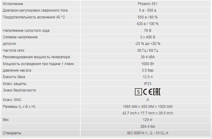
Page 47: Phoenix 551 Fdw
Technical data Phoenix 551 FDW Phoenix 551 FDW MIG/MAG 5 A–550 A Setting range for welding current 10.2 V–32.0 V 20.2 V–42.0 V 14.3 V–41.5 V Setting range for welding voltage 550 A (60% DC) Duty cycle at 40 °C (100% DC) 420 A (100% DC) 10 min.
-
Page 48: Accessories
Accessories System components Accessories Performance-dependent accessories like torches, workpiece leads, electrode holders or intermediate hose packages are available from your authorised dealer. System components Type Designation Item no. drive 4X LP Wire feeder, water-cooled, Euro torch connector 090-005412-00502 drive 4X LP MMA Wire feeder, water-cooled, Euro torch connector 090-005412-51502 with connection capability for electrode holder or…
-
Page 49: Computer Communication
Accessories Computer communication Computer communication Type Designation Item no. PC300.Net PC300.Net welding parameter software kit incl. 090-008777-00000 cable and SECINT X10 USB interface FRV 7POL 5 m Extension/connecting cable 092-000201-00003 FRV 7POL 10 m Extension/connecting cable 092-000201-00000 FRV 7POL 20 m Extension/connecting cable 092-000201-00001 QDOC9000 V2.0…
-
Page 50: Overview Of Ewm Branches
Appendix A Overview of EWM branches Appendix A 10.1 Overview of EWM branches 099-005325-EW501 01.02.2017…
Технические характеристики
Инструкция по эксплуатации
https://www.ewm-sales.com/upload/099-005325-EW508.pdf
|
Detail Specifications: 946/946016-phoenix_351551_progress_puls_mm_fdw.pdf file (14 Mar 2023) |
Accompanying Data:
EWM Phoenix 351-551 Progress puls MM FDW Welding System PDF Operating Instructions Manual (Updated: Tuesday 14th of March 2023 12:33:33 PM)
Rating: 4.5 (rated by 38 users)
Compatible devices: Tetrix 200 MV Comfort puls 5P TG, Phoenix 355 Progress puls MM TKM, Pico 300 cel, alpha Q 330 Progress puls MM TKM, TETRIX 270 AC/DC COMFORT activArc, Taurus 355 Synergic S HP MM TKW, Drive XQ IC D200, Microplasma 25.
Recommended Documentation:
Text Version of Operating Instructions Manual
(Ocr-Read Summary of Contents, UPD: 14 March 2023)
Recommended Instructions:
CyberPower RMCARD201, CVM97 Series, V2426A-C2, Intell-Lab IL-0.0001 g


-
39, quai de Marne 51 206 EPERNAY France FR- Retrouvez la liste de nos distributeurs sur www.virax.com EN – Find the list of our dealers on www.virax.com IT – Trova il rivenditore Virax più vicino a te su www.virax.com ES — Encuentra el listado de distribuidores en www.virax.com PT — Encontre a lista de nossos revendedores www.virax.com …
Cobraz 28 63
-
POTENZA 160POTENZA 200 CELPOTENZA 200Manual de instruccionesESIstruzioni d’usoITOperating instructionsGBInstructions d´emploiFRManual de instruçõesPwww.imaport.comÁrea Empresarial Andalucía — Sector ICalle Sierra de Cazorla nº7C.P: 28320 Pinto (Madrid) [email protected]@imaport.com …
POTENZA 160 40
-
Cod.006.0001.0420 21/06/2019 v2.14 ENGLISH WECO srl Via S. Antonio, 22 — BELVEDERE 36056 TEZZE SUL BRENTA (VICENZA) ITALY Tel.+39 0424 561943 — Fax +39 0424 561944 www.weco.it — E-mail [email protected] Discovery 161MF Discovery 161MF TP GB Instruction manual …
Discovery 161MF 23
-
®MIG-100 WELDERMIG-100 WELDERMIG-100 WELDERMIG-100 WELDERMIG-100 WELDERWITH THERMAL OVERLOADWITH THERMAL OVERLOADWITH THERMAL OVERLOADWITH THERMAL OVERLOADWITH THERMAL OVERLOADASSEMBLY AND OPERATING INSTRUCTIONS3491 Mission Oaks Blvd., Camarillo, CA 93011Visit our Web site at http://www.harborfreight.comCopyright© 2004 by Harbor Freight Tools®. All rights reserved. No po …
MIG-100 91124 13