- Manuals
- Brands
- EWM Manuals
- Welding System
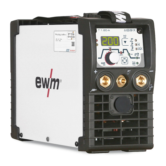
- Picotig 200 puls TG
- Operating instructions manual
-
Contents
-
Table of Contents
-
Bookmarks
Quick Links
Operating instructions
Welding machine
EN
Picotig 200 puls TG
099-002058-EW501
30.05.2017
Related Manuals for EWM Picotig 200 puls TG
Summary of Contents for EWM Picotig 200 puls TG
-
Page 1
Operating instructions Welding machine Picotig 200 puls TG 099-002058-EW501 30.05.2017… -
Page 2: General Instructions
+49 2680 181-0. A list of authorised sales partners can be found at www.ewm-group.com. Liability relating to the operation of this equipment is restricted solely to the function of the equipment.
-
Page 3: Table Of Contents
Contents Notes on the use of these operating instructions Contents 1 Contents …………………………3 2 For your safety ……………………….5 Notes on the use of these operating instructions …………….5 Explanation of icons ……………………6 Part of the complete documentation ………………..7 Safety instructions ……………………..
-
Page 4
10 Appendix A ……………………….46 10.1 Parameter overview – setting ranges ………………46 10.1.1 TIG welding ……………………46 10.1.2 MMA welding …………………… 46 10.1.3 Basic parameters (independent of process) …………..47 11 Appendix B ……………………….48 11.1 Overview of EWM branches………………….48 099-002058-EW501 30.05.2017… -
Page 5: For Your Safety
For your safety Notes on the use of these operating instructions For your safety Notes on the use of these operating instructions DANGER Working or operating procedures which must be closely observed to prevent imminent serious and even fatal injuries. •…
-
Page 6: Explanation Of Icons
For your safety Explanation of icons Explanation of icons Symbol Description Symbol Description Indicates technical aspects which the Activate and release/tap/tip user must observe. Switch off machine Release Switch on machine Press and keep pressed Switch Wrong Turn Numerical value – adjustable Correct Menu entry Signal light lights up in green…
-
Page 7: Part Of The Complete Documentation
For your safety Part of the complete documentation Part of the complete documentation These operating instructions are part of the complete documentation and valid only in combination with all other parts of these instructions! Read and observe the operating instructions for all system components, especially the safety instructions! The illustration shows a general example of a welding system.
-
Page 8
For your safety Safety instructions WARNING Hazard when interconnecting multiple power sources! If a number of power sources are to be connected in parallel or in series, only a technical specialist may interconnect the sources as per standard IEC 60974-9:2010: Installation and use and German Accident Prevention Regulation BVG D1 (formerly VBG 15) or country-specific regulations. -
Page 9
For your safety Safety instructions CAUTION Smoke and gases! Smoke and gases can lead to breathing difficulties and poisoning. In addition, solvent vapour (chlorinated hydrocarbon) may be converted into poisonous phosgene due to the ultraviolet radiation of the arc! • Ensure that there is sufficient fresh air! •… -
Page 10: Transport And Installation
For your safety Transport and installation CAUTION According to IEC 60974-10, welding machines are divided into two classes of electromagnetic compatibility (the EMC class can be found in the Technical data) > see 8 chapter: Class A machines are not intended for use in residential areas where the power supply comes from the low-voltage public mains network.
-
Page 11
For your safety Transport and installation CAUTION Risk of accidents due to incorrectly installed leads! Incorrectly installed leads (mains, control and welding leads or intermediate hose packages ) can present a tripping hazard. • Lay the supply lines flat on the floor (avoid loops). •… -
Page 12: Intended Use
In case of unauthorised changes, improper repairs, non-compliance with specified deadlines for «Arc Welding Equipment – Inspection and Testing during Operation», and/or prohibited modifications which have not been explicitly authorised by EWM, this declaration shall be voided. An original document of the specific declaration of conformity is included with every product.
-
Page 13: Machine Description — Quick Overview
Machine description – quick overview Front view Machine description – quick overview Front view Figure 4-1 Item Symbol Description Carrying strap > see 5.1.4 chapter Machine control > see 4.3 chapter Connection socket, “+” welding current How to connect the accessories depends on the welding procedure. Please observe the connection description for the corresponding welding procedure >…
-
Page 14: Rear View
Machine description – quick overview Rear view Rear view Figure 4-2 Item Symbol Description Main switch, machine on/off Cooling air inlet Mains connection cable > see 5.1.6 chapter G¼” connecting nipple Shielding gas connection on the pressure regulator. Connection socket, 19-pole Remote control connection 099-002058-EW501 30.05.2017…
-
Page 15: Machine Control — Operating Elements
Machine description – quick overview Machine control – Operating elements Machine control – Operating elements The setting ranges for the parameter values are summarised in the parameter overview section > see 10.1 chapter. Figure 4-3 Item Symbol Description Welding data display (3-digit) Displays the welding parameters and the corresponding values >…
-
Page 16
Machine description – quick overview Machine control – Operating elements Item Symbol Description Welding procedure/power-saving mode push-button —- MMA welding — TIG welding (non-latched operating mode) TIG welding (latched operating mode) Signal light green: HF start (contactless) switched on (ex works) Signal light red: Liftarc (contact ignition) switched on STBY — Press for 2 s to put the machine into power-saving mode. -
Page 17: Design And Function
Design and function Transport and installation Design and function WARNING Risk of injury from electric shock! Contact with live parts, e.g. welding current sockets, is potentially fatal! • Follow safety instructions on the opening pages of the operating instructions. • Commissioning may only be carried out by persons who have the relevant expertise of working with arc welding machines! •…
-
Page 18: Ambient Conditions
Design and function Transport and installation 5.1.3 Ambient conditions T he machine must not be operated in the open air and must only be set up and operated on a suitable, stable and level base! • The operator must ensure that the ground is non-slip and level, and provide sufficient lighting for the place of work.
-
Page 19: Notes On The Installation Of Welding Current Leads
Design and function Transport and installation 5.1.5 Notes on the installation of welding current leads Use an individual welding lead to the workpiece for each welding machine! Figure 5-2 Fully unroll welding current leads, torch hose packages and intermediate hose packages. Avoid loops! Always keep leads as short as possible! Lay any excess cable lengths in meanders.
-
Page 20: Mains Connection
Design and function Transport and installation Figure 5-4 5.1.6 Mains connection DANGER Hazards caused by improper mains connection! An improper mains connection can cause injuries or damage property! • Only operate machine using a socket that has correctly fitted protective earth. •…
-
Page 21: Welding Data Display
Design and function Welding data display Welding data display The machine will be calibrated for approx. 2 seconds each time it is switched on. This will be indicated by on the display. Subsequently, the value set for the dynamic power adjustment will be displayed for approx.
-
Page 22: Connection Assignment, Welding Torch Control Cable
Design and function TIG welding 5.3.1.1 Connection assignment, welding torch control cable TIG welding machines are equipped ex works with a dedicated connection socket for the welding torch control cable (5- or 8-pole). As mobile machines offer more free space, they may even feature two control cable connection sockets.
-
Page 23: Shielding Gas Hose Connection
Design and function TIG welding • Before connecting the pressure regulator to the gas cylinder, open the cylinder valve briefly to blow out any dirt. • Tighten the pressure regulator screw connection on the gas bottle valve to be gas-tight. •…
-
Page 24: Arc Ignition
Design and function TIG welding 5.3.3 Arc ignition To change the ignition type, use parameter to switch between HF start ( ) and lift arc ( ) in the Expert menu > see 5.3.7 chapter. 5.3.3.1 HF ignition Figure 5-10 The arc is started without contact from high-voltage ignition pulses.
-
Page 25: Welding Task Selection
Design and function TIG welding 5.3.4 Welding task selection Figure 5-12 This completes the basic settings and you can now start welding. Further welding parameters, such as gas pre-flow time, are predefined for the most common applications but can be adjusted when necessary > see 5.3.7 chapter. 5.3.5 Operating modes (functional sequences) Using the welding parameter push-button and welding parameter setting rotary knob the sequence…
-
Page 26: Tig Non-Latched Operation
Design and function TIG welding 5.3.5.2 TIG non-latched operation When the foot-operated remote control RTF is connected, the machine switches automatically to non-latched operation. The up- and down-slopes are switched off. Figure 5-13 cycle: • Press and hold torch trigger 1. •…
-
Page 27: Tig Latched Operation
Design and function TIG welding 5.3.5.3 TIG latched operation Figure 5-14 cycle • Press torch trigger 1 , the gas pre-flow time elapses. • HF start pulses jump from the electrode to the workpiece. The arc ignites. • Welding current flows and immediately assumes the set ignition current (search arc at minimum setting).
-
Page 28: Welding Torch (Operating Variants)
Design and function TIG welding 5.3.6 Welding torch (operating variants) Different torch versions can be used with this machine. Functions on the operating elements, such as torch triggers (BRT), rockers or potentiometers, can be modified individually via torch modes. Explanation of symbols for operating elements: Symbol Description Press torch trigger…
-
Page 29
Design and function TIG welding Standard torch with two torch triggers Figure Operating Explanation of symbols elements BRT1 = torch trigger 1 BRT2 = torch trigger 2 Functions Mode Operating elements Welding current on/off Secondary current (ex works) Secondary current (tapping function) )/(latched operating mode) Welding current on/off Secondary current (tapping function) -
Page 30
Design and function TIG welding Standard torch with one rocker (rocker, two torch triggers) Figure Operating Explanation of symbols elements BRT 1 = torch trigger 1 BRT 2 = torch trigger 2 Functions Mode Operating elements Welding current on/off Secondary current (ex works) Secondary current (tapping function) )/(latched operating mode) -
Page 31: Expert Menu (Tig)
Design and function MMA welding 5.3.7 Expert menu (TIG) To change the advanced setting parameters, hold down the «Welding parameters» button for 2 seconds after selecting the welding process. The following diagram shows the setting options. ENTER EXIT Figure 5-15 Display Setting/selection Switch ignition mode…
-
Page 32: Connecting The Electrode Holder And Workpiece Lead
Design and function MMA welding 5.4.1 Connecting the electrode holder and workpiece lead Polarity depends on the instructions from the electrode manufacturer given on the electrode packaging. Figure 5-16 Item Symbol Description Electrode holder Connection socket, “-” welding current Workpiece lead or electrode holder connection Workpiece Connection socket for «+»…
-
Page 33: Hotstart
Design and function MMA welding 5.4.2.1 Hotstart The hot start function improves the arc striking. After striking the stick electrode, the arc ignites at the increased hot start current and decreases to the set main current once the hot start time has elapsed. For parameter setting, >…
-
Page 34: Expert Menu (Mma)
Design and function Pulse welding 5.4.3 Expert menu (MMA) To change the advanced setting parameters, hold down the «Welding parameters» button for 2 seconds after selecting the welding process. The following diagram shows the setting options. ENTER EXIT Figure 5-20 Display Setting/selection Hotstart current…
-
Page 35: Pulse Welding
Design and function Pulse welding Pulse welding Average value pulse welding means that two currents are switched periodically, a current average value (AMP), a pulse current (Ipuls), a balance ( ) and a frequency ( ) having been defined first. The predefined ampere current average value is decisive, the pulse current (Ipuls) is defined by the parameter as a percentage of the current average value (AMP).
-
Page 36: Remote Control
Design and function Remote control Remote control The remote controls are operated on the 19-pole remote control connection socket (analogue). 5.6.1 RTF1 19POL Functions • Infinitely adjustable welding current (0% to 100%) depending on the preselected main current on the welding machine. •…
-
Page 37
Design and function Machine configuration menu Display Setting/selection Calibration The machine will be calibrated for approx 2 seconds each time it is switched on. Exit the menu Exit Torch configuration menu Set welding torch functions Torch mode (ex works 1) > see 5.3.6.2 chapter Up/down speed >… -
Page 38: Maintenance, Care And Disposal
Maintenance, care and disposal General Maintenance, care and disposal General DANGER Risk of injury due to electrical voltage after switching off! Working on an open machine can lead to fatal injuries! Capacitors are loaded with electrical voltage during operation. Voltage remains present for up to four minutes after the mains plug is removed.
-
Page 39: Maintenance Work, Intervals
A periodic test according to IEC 60974-4 «Periodic inspection and test» has to be carried out. In addition to the regulations on testing given here, the relevant local laws and regulations must also be observed. For more information refer to the «Warranty registration» brochure supplied and our information regarding warranty, maintenance and testing at www.ewm-group.com! 099-002058-EW501 30.05.2017…
-
Page 40: Disposing Of Equipment
In addition to this, returns are also possible throughout Europe via EWM sales partners. Meeting the requirements of RoHS We, EWM AG in Mündersbach, Germany, hereby confirm that all products which we supply to you and that are subject to the RoHS directive comply with RoHS requirements (also see applicable EC directives on the Declaration of Conformity on your machine).
-
Page 41: Rectifying Faults
Rectifying faults Checklist for rectifying faults Rectifying faults All products are subject to rigorous production checks and final checks. If, despite this, something fails to work at any time, please check the product using the following flowchart. If none of the fault rectification procedures described leads to the correct functioning of the product, please inform your authorised dealer.
-
Page 42: Error Messages (Power Source)
Rectifying faults Error messages (power source) Pore formation I nadequate or missing gas shielding Check shielding gas setting and replace shielding gas cylinder if necessary Shield welding site with protective screens (draughts affect the welding result) …
-
Page 43: Resetting Welding Parameters To The Factory Settings
Rectifying faults Resetting welding parameters to the factory settings Resetting welding parameters to the factory settings All customised welding parameters that are stored will be replaced by the factory settings. Figure 7-1 Display Setting/selection Calibration The machine will be calibrated for approx 2 seconds each time it is switched on. Initialising Keep the push-button pressed until «InI»…
-
Page 44: Technical Data
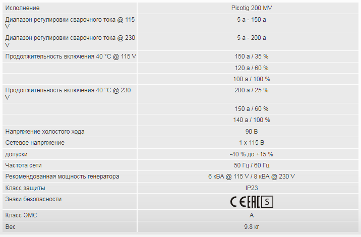
Technical data Picotig 200 Technical data Performance specifications and guarantee only in connection with original spare and replacement parts! Picotig 200 5 A–200 A 5 A–150 A Setting range for welding current Setting range for welding voltage 10.2 V–18.0 V 20.2 V–26.0 V Duty cycle (DC) at 40 °C 200 A…
-
Page 45: Accessories
Accessories Transport systems Accessories Performance-dependent accessories like torches, workpiece leads, electrode holders or intermediate hose packages are available from your authorised dealer. Transport systems Type Designation Item no. Trolly 35-1 Transport vehicle 090-008629-00000 Options Type Designation Item no. ON Filter Pico/Picotig 180/200 Dirt filter for air inlet 092-002546-00000 ON Safeguard M Insulating protective cover…
-
Page 46: Parameter Overview — Setting Ranges
Appendix A Parameter overview – setting ranges Appendix A Parameter overview – setting ranges 10.1 10.1.1 TIG welding Parameters/function Setting range Secondary current AMP% Down-slope time Gas post-flow time Pulse welding Pulse frequency — 2000 HF start Gas pre-flow time Ignition current Up-slope time 20,0…
-
Page 47: Basic Parameters (Independent Of Process)
Appendix A Parameter overview – setting ranges 10.1.3 Basic parameters (independent of process) Parameters/function Setting range Switched on Switched off Calibration Initialisation Machine configuration Exit menu Torch configuration Torch mode Up/down speed Service menu Dynamic power adjustment (10 A, 16 A, 20 A) Time-based power-saving mode min.
-
Page 48: Overview Of Ewm Branches
Appendix B Overview of EWM branches Appendix B 11.1 Overview of EWM branches 099-002058-EW501 30.05.2017…
Read the operating instructions!
The operating instructions provide an introduction to the safe use of the products.
•
Read and observe the operating instructions for all system components, especially the
safety instructions and warning notices!
•
Observe the accident prevention regulations and any regional regulations!
•
The operating instructions must be kept at the location where the machine is operated.
•
Safety and warning labels on the machine indicate any possible risks.
Keep these labels clean and legible at all times.
•
The machine has been constructed to state-of-the-art standards in line with any applicable
regulations and industrial standards. Only trained personnel may operate, service and
repair the machine.
•
Technical changes due to further development in machine technology may lead to a
differing welding behaviour.
In the event of queries on installation, commissioning, operation or special conditions at the
installation site, or on usage, please contact your sales partner or our customer service
department on +49 2680 181-0.
A list of authorised sales partners can be found at www.ewm-group.com.
Liability relating to the operation of this equipment is restricted solely to the function of the
equipment. No other form of liability, regardless of type, shall be accepted. This exclusion of
liability shall be deemed accepted by the user on commissioning the equipment.
The manufacturer is unable to monitor whether or not these instructions or the conditions and
methods are observed during installation, operation, usage and maintenance of the equipment.
An incorrectly performed installation can result in material damage and injure persons as a
result. For this reason, we do not accept any responsibility or liability for losses, damages or
costs arising from incorrect installation, improper operation or incorrect usage and maintenance
or any actions connected to this in any way.
© EWM AG
Dr. Günter-Henle-Straße 8
56271 Mündersbach
Germany
The copyright to this document remains the property of the manufacturer.
Copying, including extracts, only permitted with written approval.
The content of this document has been prepared and reviewed with all reasonable care. The information
provided is subject to change; errors excepted.
WARNING
|
Detail Specifications: 1879/1879250-picotig_200_puls_tg.pdf file (03 May 2023) |
Accompanying Data:
EWM Picotig 200 puls TG Welding System PDF Operating Instructions Manual (Updated: Wednesday 3rd of May 2023 11:04:08 AM)
Rating: 4.2 (rated by 63 users)
Compatible devices: Picomig 355 puls TKM, Pico 350 cel puls vrd, Microplasma 25, Wega 401 FDG, Pico 220 cel puls vrd, UM 24 G EZA, Taurus **5 Basic S Series, Phoenix 351-551.
Recommended Documentation:
Text Version of Operating Instructions Manual
(Ocr-Read Summary of Contents, UPD: 03 May 2023)
-
20, Design and function Transport and installation 20 099-002058-EW501 26.11.2020 5.1.5 Notes on the installation of welding current leads • Use an individual welding lead to the workpiece for each welding machine! Figure 5-2 • Fully unroll welding current leads, torch hose packages and intermediate hose packages. Avoid loops! • Always…
-
5, For your safety Notes on using these operating instructions 099-002058-EW501 26.11.2020 5 2 For your safety 2.1 Notes on using these operating instructions DANGER Working or operating procedures which must be closely observed to prevent imminent serious and even fatal injuries. • Safety notes include the «DANGER» keyword in the heading with a general…
-
36, Design and function MMA welding 36 099-002058-EW501 26.11.2020 5.3.3 Hotstart The function hot start ensures a secure igniting of the arc and a sufficient heating to the still cold parent metal at the beginning of the welding process. The ignition takes place here with increased current (hot start current) over a certain time (hot start time). Fo…
-
16, EWM Picotig 200 puls TG Machine description – quick overview Machine control – Operating elements 16 099-002058-EW501 26.11.2020 4.3 Machine control – Operating elements The parameters and their setting ranges are described in chapter Parameters Overview — Setting Ran- ges > see 10.1 chapter. Figure 4-3 Item Symbol Description 0 1 AMP% Secondary current (TIG) 2 W…
-
27, EWM Picotig 200 puls TG Design and function TIG welding 099-002058-EW501 26.11.2020 27 5.2.4 Welding task selection Figure 5-12 This completes the basic settings and you can now start welding. Further welding parameters, such as gas pre-flow time, are predefined for the most common applications but can be adjusted when necessary > see 5.2.8 chapter. 5.2.5 Ope…
-
22, Design and function Transport and installation 22 099-002058-EW501 26.11.2020 5.1.7 Mains connection DANGER Hazards caused by improper mains connection! An improper mains connection can cause injuries or damage property! • The connection (mains plug or cable), the repair or voltage adjustment of the device must be carried out by a qualifi…
-
14, Machine description – quick overview Front view 14 099-002058-EW501 26.11.2020 4 Machine description – quick overview 4.1 Front view Figure 4-1 Item Symbol Description 0 1 Carrying strap > see 5.1.4.1 chapter 2 Machine control > see 4.3 chapter 3 Connection socket, “+” welding current How to connect the …
-
6, For your safety Explanation of icons 6 099-002058-EW501 26.11.2020 2.2 Explanation of icons Symbol Description Symbol Description Indicates technical aspects which the u- ser must observe. Activate and release / Tap / Tip Switch off machine Release Switch on machine Press and hold Switch Incorr…
-
35, Design and function MMA welding 099-002058-EW501 26.11.2020 35 5.3 MMA welding 5.3.1 Connecting the electrode holder and workpiece lead CAUTION Risk of crushing and burns! When changing stick electrodes there is a risk of crushing and burns! • Wear appropriate and dry protective gloves. • Use an insulated pair of tongs to remove the…
-
48, EWM Picotig 200 puls TG Technical data Picotig 200 48 099-002058-EW501 26.11.2020 8 Technical data Performance specifications and guarantee only in connection with original spare and replacement parts! 8.1 Picotig 200 TIG MMA Welding current (I 2 ) 5 A to 200 A 5 A to 150 A Welding voltage according to standard (U 2 ) 10,2 V to 18,0 V 20,2 V to 26,0 V Duty cycle DC at 40° C…
Recommended Instructions:
BHL 3040, XM5, 509, COS200, VEC-11


-
BPSMIG140 FR POSTE DE SOUDURE TRADUCTION DES INSTRUCTIONS D’ORIGINE NL LASAPPARAAT VERTALING VAN DE ORIGINELE INSTRUCTIES GB WELDER ORIGINAL INSTRUCTIONS S52 M12 Y2013 …
BPSMIG140 38
-
Recommended Parts ListforHP NetServer LH4 withHP Rack Storage/12FC & Rack Storage/1229 June 1999The components listed below are required for this cluster solution. This list is providedto assistant you in ordering the required and proper components for your cluster. Referto HP Rack Assistant to develop a parts list for the rack parts and accessories.1DPH 0RGHO� …
D7171A — NetServer — LPr 1
-
1NoticeThis manual and any examples contained herein are provided “as is” and are subject to change without notice. Hewlett-Packard Company makes no warranty of any kind with regard to this manual, including, but not limited to, the implied warranties of merchantability and fi tness for a particular purpose. Hewlett-Packard Co. shall not be liable for any …
X09 54
Additional Information:
Popular Right Now:
Operating Impressions, Questions and Answers:
EWM Manuals and Guides:
The main types of EWM Picotig 200 puls TG instructions: user guide — rules of useing and characteristics, service manual — repair, diagnostics, maintenance, operation manual — description of the main functions of EWM Picotig 200 puls TG equipment, etc.
Most of the instructions, that you can see on the site are uploaded by our users. If you have available a manual or document for EWM Picotig 200 puls TG, which is currently not on the site or present in a different language version, we ask you to upload your document on website, using the «uploading form» available to all registered users.
Технические характеристики
Инструкция по эксплуатации
https://www.ewm-sales.com/upload/099-002059-EW508.pdf
https://www.ewm-sales.com/upload/099-002058-EW508.pdf