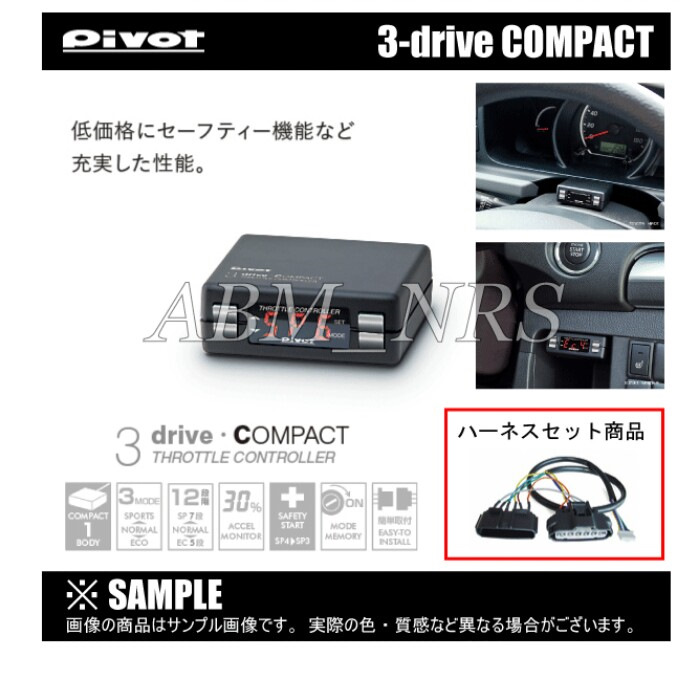
Что такое и для чего Throttle controller в первой части записи.
Установка
Глушим автомобиль (зажигание в положении «OFF»).
1. Разбираем рулевую колонку и панель со стороны водителя. Собираем и прокладываем провода контроллера по рулевой колонке (к педале газа и диагностическому разъёму автомобиля)
2. Питание контроллера осуществляется через коннектор подсоединяющийся к диагностическому разъему автомобиля, но у меня в нём всегда вставлен ELM 327, поэтому мне пришлось ампутировать коннектор и подключить контроллер к проводке автомобиля.
3. Спустя минимум 15 минут отсоединяем фишку от педали газа, вставляем ее в фишку от блока контроллера, вторую фишку овставляем в педаль. Получается, что мы «вжились» в педаль (если не ждать, то может появиться ДжекиЧан при вытаскивании фишки с педали) после этого крепим провода, монитор на рулевой колонке и всё собираем.
Настройка
Машина должна стоять на парковке или нейтрале.
1.Включаем зажигание (чтобы все лампочки на приборке горели, но двигатель не заводим);
2.Нажимаем на 12 сек. кнопку SET, на дисплее пойдёт обратный отчёт, ждем пока не загорится НОЛЬ;
3.Отпускаем кнопку, дисплей покажет Н 4,2 ;
4.Нажимаем на кнопку SET, на экране появляется надпись SET, не отпуская кнопки жмем педаль газа в пол, до появления 100, оптускаем кнопку SET.
5.Отпускаем педаль газа — видим значение NOR, нажимаем педаль газа циферки бегают от 0 до 100 в зависимости от нажатия.
Настройка завершена.
.
USER’S MANUAL
Thank you for purchasing PIVOT product.
Please read this manual carefully and keep it for future reference.
• If this product is given to another
user, make sure to include this
User’s Manual.
Contents
Before Using / WARNING / CAUTION …………………………1
Contents ………………………………………………………… 2
Features……………………………………………………………2
1
2
procedure
After installation, make sure to carry out «Initial Settings».
After having installed this product, make sure to make settings for your car’s special characteristics by carrying out the «Initial
Settings» on Page 5. If the «Initial Settings» are not carried out, a Check Engine Light may go on. Also, the unit will remain in
NORMAL Mode even if the Mode is switched.
Worried about Installation?
If you are worried about carrying out wiring or other installation procedures please consult your dealer.
Only use 3-drive Specialized Harness.
Using another type of harness will cause troubles and failure; use only the 3-drive specialized harness.
Set to NORMAL Mode upon Removal of Product.
When uninstalling the product, make sure to return it to
a different mode may cause the Check Engine Light to come on.
Modifying this Product is Forbidden.
Under no circumstances should modifications or changes be made to this product. Doing so may cause damage not only to the product,
but to the car and the operation of the car in which it is installed.
• When making initial settings make sure
WARNING
Improper use or disregard
of these war nings may
• Do not work in areas where there is
result in the injury or death
of people.
• PIVOT Corporation accepts no responsi-
CAUTION
• Please confirm that the type of vehicle
Improper use or disregard
of these war nings may
cause injury to persons,
damage the product and/or
• When installing this product, we recom-
other things.
(
Product Number :
THC
+
Product
nor
(NORMAL) Mode before carrying out any work. Reconnecting this product in
to stop the engine and place in Parking
or Neutral. It is dangerous to carry out
t h e s e s e t t i n g s w h i l e t h e e n g i n e i s
running.
e x c e s s i v e e x h a u s t . D u e t o v e h i c l e
exhaust emission poisoning or fire may
result in a damage to humans.
bilit y, in any manner whatsoever, for
damage and/or trouble to your vehicle or
product, nor for any accidents that are
the result of the misuse of this product.
you wish to install into is listed in the
«List of Specialized Harnesses by Car
Model for 3-drive · COMPACT».
m e n d t h a t i f t e c h n i c a l k n o w l e d g e
becomes necessar y please consult a
qualified mechanic.
)
Throttle Controller
3
3
Initial Settings
(Degree of Acceleration Setting)
How to Operate……………………………………………… 6-7
Troubleshooting ………………………………………………… 7
• Do not crush the cable. Please be
careful that the cable does not
get crushed by the seat rail or car
door steel plate, nor cut by any
s h ar p s te e l p l ate a s t h i s m ay
cause a poor connection or an
electric shor t leading to fire or
other danger.
• I f t h e d e v i c e i s i m p r o p e r l y
installed or settings have been
improperly made a Check Engine
Light may go on.
• Do not use electrotap.
• W i r i n g s h o u l d b e c a r r i e d o u t
using the attached «cut connec-
tor» or by soldering, make sure to
securely insulate all wiring parts
with insulation tape, and confirm
that no wires are sticking out.
(THC As of November, 2016 No.19)
drive・ C OMPACT
THROTTLE CONTROLLER
…… 5
• While driving DO NOT operate
s w i t c h e s o r p ay p r o l o n g e d
attention to the display; it is
extremely dangerous.
• Make sure that all wiring and
fastening down of the product
does not interfere with driving
nor be done in such a way as
to cause poor connections.
• Please wipe with a sof t dr y
cloth (a lens cloth).
• Please do not use alcohol or
benzine.
This may cause damage to
the painted surface or cracks
in the plastic.
• D o n o t , i n a n y m a n n e r ,
process, take apart, or make
changes to this product.
1
USER’S MANUAL
Thank you for purchasing PIVOT product.
Please read this manual carefully and keep it for future
reference.
If this product is given to another
user, make sure to include this
User’s Manual.
Contents
Before Using …………………………………………………… 1
Product Features …………………………………………… 2 — 3
Features……………………………………………………… 2
Contents …………………………………………………… 2
WARNING / CAUTION ……………………………………… 3
1
Clutch Signal ………………………………………………… 4
Brake Switch / Earth / Car Speed Signal
2
After installation, make sure to carry out «Initial Settings».
After having installed this product, make sure to make settings for your car’s special characteristics by
carrying out the «Initial Settings» on Page 7. If the «Initial Settings» are not carried out, a Check Engine
Light may go on. Also, the unit will remain in NORMAL Mode even if the Mode is switched.
Worried about Installation?
If you are worried about carrying out wiring or other installation procedures please consult your dealer.
Only use 3-drive Specialized Harness.
Using another type of harness will cause troubles and failure; use only the 3-drive specialized harness.
Set to NORMAL Mode upon Removal of Product.
When uninstalling the product, make sure to return it to
Reconnecting this product in a different mode may cause the Check Engine Light to come on.
Modifying this Product is Forbidden.
Under no circumstances should modifications or changes be made to this product. Doing so may cause damage
not only to the product, but to the car and the operation of the car in which it is installed.
(
Product Number :
BLP
+
Product
…………… 5 — 6
Throttle Controller with Built-in MT Auto-Blipping Function
)
3
drive・BLP
BLIPPING & THROCON
3
Initial Settings
(Degree of Acceleration Setting)
procedure
4
How to Operate……………………………………………… 8-10
Basic Operation ……………………………………………… 11
Troubleshooting ………………………………………… 11-12
nor
(NORMAL) Mode before carrying out any work.
(BLP As of November, 2016 No.7)
…… 7
1
|
Detail Specifications: 1387/1387068-3_drive_blp.pdf file (27 Feb 2023) |
Accompanying Data:
Pivot 3 drive BLP Controller PDF Operation & User’s Manual (Updated: Monday 27th of February 2023 08:07:08 PM)
Rating: 4.8 (rated by 52 users)
Compatible devices: RC700, NEW GREEN SERIES, Allen-Bradley 150-E, ELVOX EG30/N, THC-M, THC, GSC400 Series, Orion.
Recommended Documentation:
Text Version of Operation & User’s Manual
(Ocr-Read Summary of Contents, UPD: 27 February 2023)
-
1, 1 + Before Using Features Connecting The Wires Installing The Product Initial Settings How to Operate Speed Pulse Settings Trouble- Shooting Thank you for purchasing PIVOT product. Please read this manual carefully and keep it for future reference. (BLP As of November, 2016 No.7) Throttle Controller with Built-in MT Auto-Blipping Function Product If this …
-
2, Pivot 3 drive BLP 2 Features Connecting The Wires Installing The Product How to Operate Speed Pulse Settings Before Using Trouble- Shooting Initial Settings Features Throttle Controller with Built-in MT Auto-Blipping Function Auto-Blipping Auto-Blipping removes the need for the conven- tional “heel and toe” technique used to raise rpm with the accelerator while braking at the same…
-
3, 3 – – Turning off the Display This product is interlocked with the ECU (engine computer) power. Depend- ing on the model of car, the display may remain on for up to 15 minutes even after the ignition has been turned to the OFF position; this is normal. Display Details SPORTS Mode (Higher number = Higher response) ECO Mode (Higher number = Lower response) NORMAL…
-
4, 4 Wiring Chart Wiring Chart ア イ ヴィッツ 車 名 H17. メーカー TOYOTA クラッチ関 係 MTC-7 クラッチ スイッチ コネクター 形状 クラッチ アダプター ○: 使 用 す る ×: 使 用 し な い クラッチアダプター のコード色 ユニットの コード色 接続記号 ア 茶紫 ピンク ○ ア イ Features Connecting The Wire…
-
5, Pivot 3 drive BLP 5 Wiring Chart Wiring Chart Red Gray 86 TOYOTA 車 名 年 式 H 24.4 ∼ BR-7 ブレーキ ハーネス 品番 直接接続 接続番号 ブレーキ ハーネス 接続色 製品のコード色 赤灰赤灰 86 TOYOTA 車 名 年 式 H 24.4 ∼ BR-7 ブレーキ ハーネス 品番 直接接続 接続番号 ブレーキ ハーネス 接続色 製品のコード色 赤灰赤灰 Wirin…
-
6, 6 Features Connecting The Wires Installing The Product How to Operate Speed Pulse Settings Before Using Trouble- Shooting Initial Settings [Reference 3] How to use the Male Connectors Controller Controller L-shaped Fastener Fastening to a Flat Place Installing The Controller Install the Controller to a position which is easy to see. Installing The Product Double-sided tape (Included) Double-sided…
-
7, 7 Press until “0” appears Release Press Press START ENGINE STOP Before Using Features Connecting The Wires Installing The Product How to Operate Speed Pulse Settings Trouble- Shooting Initial Settings Make sure to carry out this operation. If after the Err is shown the display returns to as shown in 4 ( L1.5 or so on), it means that the degree…
-
8, 8 START ENGINE STOP Press the switch for 3 seconds Release Press 3 seconds Features Connecting The Wires Installing The Product How to Operate Speed Pulse Settings Before Using Trouble- Shooting Initial Settings Accelerator Degree of acceleration Time length of operation Range of settings Adjustment unit [Value of settings] Basic value of settingsInitial value Engine Start. Degree …
-
9, Pivot 3 drive BLP 9 6 6 7 5 5 4 START 6 5 4 4 3 3 2 Before Using Features Connecting The Wires Installing The Product Initial Settings How to Operate Speed Pulse Settings Trouble- Shooting Start the Test Run. (40 km/h, not lower than 3rd gear) Engine Start. Please carry out the test drive in a safe spacious area away from pedestrians and traffic. Please make sure to carefully read this manual and understa…
-
10, 10 Press — Features Connecting The Wires Installing The Product How to Operate Speed Pulse Settings Before Using Trouble- Shooting Initial Settings Degree of Acceleration (output) 20% ECO Mode SPORTS Mode NORMAL Mode [Reference 2] Basic Control Features Acceleration Output Signal (at degree monitor)(%) Amount of pressure placed on the accelerator pedal (%) Press down on …
-
11, 11 Before Using Features Connecting The Wires Installing The Product Initial Settings How to Operate Speed Pulse Settings Trouble- Shooting [With Auto-Blipping] [Without Auto-Blipping] Slip RPM RPM G G Throttle Opening 27% Throttle Opening 50% Throttle Opening 89% Trouble Concerning Basic Operations and Car Problems Possible Causes Possible Solutions Troubleshooting Make the “Initi…
-
12, Pivot 3 drive BLP 12 PIVOT CORPORATION 87-3, Shimookada Okada, Matsumoto-shi, Nagano, 390-0313 Japan Check Engine Light is ON Features Connecting The Wires Installing The Product How to Operate Speed Pulse Settings Before Using Trouble- Shooting Initial Settings Concerning the Throttle Controller Trouble Possible Causes Possible Solutions Concerning Auto-Blipping Trouble Possible Causes Possible Solutions The …
Recommended Instructions:
dLAN 500 WiFi, ProNautic1210P, 73SC005A1C, Sonic 2018


-
A Quick Start Guide to the Model 54USER DOCUMENTATION AND UTILITY SOFTWAREUser documentation, utility software, LabView drivers and sensor curves are on the CD provided. Additionally, they are available at: http://www.cryocon.com/CCdownload/CustomerCD12.zipBASIC FRONT PANEL OPERATIONPressing the Power key will toggle the controller’s AC power on and off. This key must be pressed and held f …
54 2
-
PC, HDMI, DISPLAY PORT, SDI INTERFACE CONTROLLER FOR TFT PANEL Model: ALR-1920-SDI Part number : 41728001X-3 or up INSTRUCTIONS CONTENTS Page: 2. Introduction, How to Proceed, Usage Note, Disclaimer 3. System design – Diagram of a suggested system 4. Assembly notes – Important information about system elements 6. Connection & …
ALR-1920-SDI 36
-
SNAP PAC R-SERIES CONTROLLER USER’S GUIDESNAP-PAC-R1SNAP-PAC-R2SNAP-PAC-R1-FMSNAP-PAC-R2-FMSNAP-PAC-R1-WSNAP-PAC-R2-WForm 1595-100826—August 201043044 Business Park Drive • Temecula • CA 92590-3614Phone: 800-321-OPTO (6786) or 951-695-3000Fax: 800-832-OPTO (6786) or 951-695-2712www.opto22.comProduct Support Services800-TEK-OPTO (835-6786) or 951-695-3080Fax: 951-695-3017Email: sup …
SNAP-PAC-R1 90
Additional Information:
Popular Right Now:
Operating Impressions, Questions and Answers:

1
Product
+
(THC-M As of August 2016 No. 2)
USER’S MANUAL
Contents
Before Using/Contents/WARNING/CAUTION ……… 1
Features/Part Names…………………………………… 2
Connecting The Wires …………………………… 3
—
4
Initial Settings (Degree of Acceleration Setting)…… 5
Installing The Product ………………………………… 6
How to Operate …………………………………… 6
—
7
Troubleshooting ………………………………………… 8
▶Do not use together with another company’ s product.
▶Worried about Installation?
●If this product is given to
another user, make sure to
include this User’s Manual.
Thank you for purchasing this PIVOT product.
Please read this manual carefully before installation
and use.
Please keep this manual for future reference.
・If the “Initial Settings” are not carried out, a CHECK Lamp may go on. Also, the unit will remain in NORMAL mode even
if the Mode is switched.
・If the product is re-installed in a different car, make sure to carry out “Initial Settings” before using.
▶After installation, make sure to carry out “Initial Settings” (⇒Page 5) before
using the product.
If you are worried about carrying out wiring or other installation procedures please consult your dealer.
The 3-drive main unit and specialized harness are designed to be used together; the guarantee does not cover use of either
part with another company’ s product.
▶When uninstalling the product, make sure to return it to NORMAL Mode before
carrying out any work.
▶This product cannot be installed in the following cars;
・The ECU is different from the standard for that model.
・If a sub-computer is being used.
●When making initial settings make sure to stop the engine.
●Do not work in areas where there is excessive exhaust.
●While driving DO NOT operate switches or pay prolonged attention to the display.
●Make sure to carry out wiring so as not to obstruct driving or cause a short.
●Do not, in any manner, take apart or make changes to this product.
WARNING
Improper use or disregard of these
warnings may result in the injury or
death of people.
●Misuse of the product may cause breakdown or trouble; please use properly.
●PIVOT Corporation accepts no responsibility for any troubles that are the result of
the misuse of this product.
●Do not use electrotap.
●Please check the details for compatible car models in “Fitting List” before purchasing.
CAUTION
Improper use or disregard of these
warnings may cause injury to persons,
damage the product and / or other
things.
Before
Using
Features
Connecting
The Wires
Installing
The Product
How to
Operate
Trouble-
Shooting
Initial
Settings
THROTTLE CONTROLLER
3
drive・COMPACT
PULSE Type
MAZDA
This product is designed for use with MAZDA pulse
model cars only; it cannot be used with other type cars.
Unit
[60×22×55 (D) mm]
User’s Manual
(This Book)
Cut
Connectors ×4
Double-sided Tapes
[25×35 mm] ×2
Extension
Cable (Black)
Specialized Harness
Zip Tie
Male Connectors ×2,
Male Sleeves ×2
Please check the contents of the package