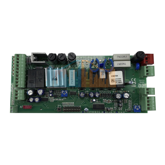
Плата блока управления CAME ZL38 разработана и изготовлена компанией CAME Cancelli Automatici S.p.A.
Используется на шлагбаумах CAME серии GARD. На блок управления подается напряжение ~230 В частотой 50/60 Гц.
Для электропитания устройств управления и аксессуаров используется ~24 В.
Внимание! Суммарная мощность дополнительных устройств не должна превышать 20 Вт.
Блок управления оснащен токовой системой защиты, которая постоянно контролирует значение тягового усилия мотора. Когда на пути движения стрелы встречается препятствие, токовая система обнаруживает излишнее тяговое усилие и выполняет следующее:
- в режиме открывания останавливает стрелу;
- в режиме закрывания стрела изменяет направление движения вплоть до полного открывания;
- В случае если функция автоматического закрывания была активирована, начнется отсчет времени перед опусканием.
Внимание! После трехкратного обнаружения препятствия и смены направления движения стрела остается в поднятом положении, а автоматическое закрывание становится невозможным: чтобы закрыть шлагбаум, используйте соответствующую кнопку управления
Плата блока управления CAME ZL38 поддерживает следующие функций и режимов работы:
- автоматическое закрывание после команды «Открыть»;
- немедленное закрывание;
- предварительное включение сигнальной лампы;
- обнаружение препятствий (по фотоэлементам) при неподвижном положении стрелы в любой точке траектории;
- открывание в режиме закрывания;
- режим «ведомый»;
- усиление торможения стрелы.
Выполняемые команды:
- открыть/закрыть
- открыть/закрыть в режиме «Присутствие оператора»;
- открывание;
- стоп.
Благодаря соответствующей регулировке можно установить:
- время срабатывания автоматического закрывания;
- чувствительность токовой системы защиты.
ВНИМАНИЕ: перед тем как приступить к подключениям, настройке или регулировке, отключите сетевое электропитание и аккумуляторы (если они используются).
Программирование пультов в плату CAME ZL38
На плате управления CAME ZL38 установлен SM-разъем (красного цвета), в разъем устанавливается плата радиоприемника Came. В зависимости от установленной платы радиоприемника, подбираются совместимые с платой управления пульты дистанционного управления. Для программирования пультов используется кнопка PROG на плате управления ZL38.
1) Нажмите и удерживайте кнопку PROG на плате блока управления (светодиодный индикатор начинает мигать).
2) Нажмите кнопку программируемого брелока-передатчика для передачи кода. Если светодиодный индикатор загорелся ровным светом, процедура программирования была проведена успешно. Важно: если в дальнейшем вы захотите поменять радиокод, достаточно повторить вышеописанную процедуру.
Полную инструкцию на плату блока управления CAME ZL38 можно скачать во вкладке СКАЧАТЬ.
Наша компания предлагает большой выбор запасных частей для замены и ремонта автоматики CAME. Вы можете запросить и приобрести необходимые запасные части у наших менеджеров
-
Contents
-
Table of Contents
-
Bookmarks
Quick Links
COMMAND BOARD FOR BARRIERS
AUTOMAZIONE PER CHIUSURA INDUSTRIALE
WITH 24V MOTOR
ZL38
INSTALLATION MANUAL
Related Manuals for CAME ZL38
Summary of Contents for CAME ZL38
-
Page 1
COMMAND BOARD FOR BARRIERS AUTOMAZIONE PER CHIUSURA INDUSTRIALE WITH 24V MOTOR ZL38 INSTALLATION MANUAL… -
Page 2
4.1 Command board Fully designed and built by CAME CANCELLI AUTOMATICI S.p.A. Guaranteed for 24 months unless tampered with. The command board is powered at 230V A.C. on the L-N terminals with 50÷60 Hz frequency and is protected in input with 3.15A fuses. -
Page 3: Technical Information
— Function that increases the braking action of the barrier; — Type of command: open-close or opening only Settings: automatic closure time adjustment, amperometric sensitivity. Optional accessories: — fl ashing dome and lighted cord; — bar open light marks the opening position of the bar; it turns off after the closing operation; — LB38 card makes it possible to power the barrier using batteries in the event of mains power outage.
-
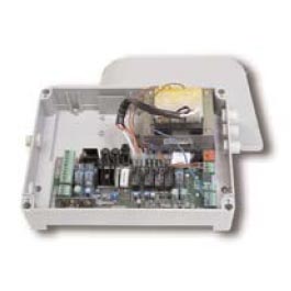
Page 4: Installation
5 Installation 5.1 Preliminary checks Before proceeding with the installation, it is necessary to: — provide for suitable omnipolar disconnection device with more than 3 mm between contacts to section power supply; connections inside the case made for protection circuit continuity are allowed as long as they include additional insulation with respect to other internal drive parts;…
-
Page 5
5.4 Installing the electrical card G2080 G4040 G2080I G4040I 1) Unscrew the four mounting screws (or three in the case of the G4040) of the cover of the container located on the upper part of the automation. ZL 38 2) Insert the card into the container and fasten it with the screws supplied. -
Page 6: Electrical Connections
5.5 Electrical connections 230V (a.c.) power supply 24V(d.c.) motor DIP 3 OFF — Flashing movement-indicating lamp (e.g.: fl ashing dome lamp, luminous cord) 24V max. 32W output DIP 3 ON — Flashing movement-indicating lamp and “Closed barrier” signalling lamp Power supply to accessories 24V max. 30W Stop button (N.C.) IF NOT USED Open button (N.O.)
-
Page 7: Function Selections
5.6 Function selections 1 ON Automatic Closing function activated; (1 OFF-deactivated); 2 ON “Open Only” function with pushbutton (2-7) and remote control (AF — board inserted) activated; 2 OFF “Open-Close-Reverse” Function with pushbutton (2-7) and remote control (HF board inserted) activated; 3 ON 24V (10-E) output activated when moving and when closed;…
-
Page 8
5.9 Connection of two pairs of barriers with a single command 1) Designate the Master barrier (or pilot, namely the motor that commands both barriers) and the Slave (motor piloted by the Master). MASTER COMMAND BOARD 2) On the command board designated as the Master, execute all the wiring connections (see page 6), the instal- lation procedure for remote control,… -
Page 9
6 Installation procedure of the transmitter for remote control Read the three steps below before beginning installation procedures: — prepare the radio board (paragraph 6.1); — procedure for codifying the transmitter (paragraph 6.2); — memorizing the code on the command board (paragraph 6.3). 6.1 Prepare the radio board (AF) 1) On AM transmitters operating at 433.92 MHz (TOP and TAM series), position the jumper connection on… -
Page 10
T262M — T302M The fi rst encoding operation must be carried out whilst keeping the jumpers po- sitioned for channels 1 and 2 as per fi g. A; see fi g. B for any subsequent settings on different channels. P1 = CH1 — P2 = CH3 P1 = CH3 — P2 = CH2 FIG.A FIG.B… -
Page 11
TOP SERIES T432M — T312M set the code to dip-switch C and channel to D (P1=CH1 and P2=CH2, default setting) T434M — T314M T432S — T432SA — T434MA — T432NA — T434NA set code only see instructions on pack P1 = CH1 P2 = CH2 P3 = CH3 P4 = CH4… -
Page 12: Mounting The Lid
6.3 Memorizing the code on the command board 1) Keep the «PROG» key pressed on the base card, the signal LED will fl ash. Radio board Flashing LED Lit LED 2) Press a transmitter key to send the code; the LED will remain lighted to signal memorization.
-
Page 13: Demolition And Disposal
UNI EN ISO 14001 standard to ensure environmental protection. Please continue our efforts to protect the environment—which CAME considers one of the cardinal elements in the development of its operational and market strategies—simply by observing brief recommendations as regards disposal: DISPOSAL OF PACKAGING –…
- Home
- Инструкции
- Автоматика для ворот
- CAME
- ZL38
![]() Электронный блок управления CAME ZL38 инструкция по монтажу на русском языке в формате pdf, размер файла 1.5 Mb. Используйте кнопки «Скачать инструкцию» или «Открыть в новом окне» (документ откроется в новом окне или вкладке браузера). Функция просмотра доступна при наличии плагина Adobe Acrobat в вашем браузере.
Электронный блок управления CAME ZL38 инструкция по монтажу на русском языке в формате pdf, размер файла 1.5 Mb. Используйте кнопки «Скачать инструкцию» или «Открыть в новом окне» (документ откроется в новом окне или вкладке браузера). Функция просмотра доступна при наличии плагина Adobe Acrobat в вашем браузере.
CAME ZL38 инструкция
Язык: Русский
Размер : 1.5 Mb
Формат файла: pdf
Добавлен: 20.06.2013
Руководство по установке
Предварительный просмотр

Информация, описание, технические характеристики изделия
Описание и информация о технических характеристиках по данному изделию пока что отсутствует. Содержание во всех разделах сайта периодически обновляется. Попробуйте зайти на страницу позже.
Отзывы по оборудованию и комментарии к материалу
Здесь можно оставить свои отзывы по оборудованию «CAME ZL38 — Блок управления», а также написать комментарии к материалу.
“IMPORTANT SAFETY INSTRUCTIONS FOR INSTALLATION”
“CAUTION: IMPROPER INSTALLATION MAY CAUSE SERIOUS DAMAGE, FOLLOW ALL INSTALLATION INSTRUCTIONS CAREFULLY”
“THIS MANUAL IS ONLY FOR PROFESSIONAL INSTALLERS OR QUALIFIED PERSONS”
1 Legend
This symbol indicates sections to be read with particular care.
This symbol indicates sections concernig safety

 This symbol indicates notes to communicate to users.
2 Destination and limits of use
2.1 Destination
The electronic command board was designed for specific use in automatic GARD 4 and GARD 8 series barriers with 24V gear motors; inserted into the container fitted with a transformer with IP54 protection level, 230V power supply with 50÷60 Hz frequency.
 Uses other than the ones described above and installations using methods other than those shown in this technical manual are considered prohibited.
2.2 Limits of use
Comply with the cable cross-sections recommended in the table under chapter 5.3
3 Standard followed
The following standard were complied with for this product: EN 12978, UNI EN 954-1, CEI EN 60335-1, UNI EN 12453.
4 Description
4.1 Command board
Fully designed and built by CAME CANCELLI AUTOMATICI S.p.A. Guaranteed for 24 months unless tampered with.
The command board is powered at 230V A.C. on the L-N terminals with 50÷60 Hz frequency and is protected in input with 3.15A fuses.
A 2A fuse protects the low-voltage (24V) command devices. 630mA control unit fuse. 10A motor fuse.
The overall rated power of the 24V accessories must not exceed 40 W.
The photoelectric cells may be connected and pre-set for:
—Re-opening during closing phases: if the photocells identify an obstacle while the gate is closing, they will reverse the direction of movement until the gate is completely open;
—Total stop: stops the bar with consequent exclusion of the automatic closing cycle; pushbuttons or transmitters must be used to resume movement.
The board also integrates and independently manages a safety function which is sensitive to obstacles (amperometric device) that:
during opening: the bar stops;
during closing: the bar reverses its direction until it opens completely; automatic closure is thus activated.
 Caution! after three consecutive direction reversals, the bar will remain up and automatic closure will be discontinued. To close the gate, use the radio remote control or the push-button.
Other selectable functions:
—Automatic closure. The automatic closure timer self-powers at the end stop in opening. The set time can be adjusted and is also subject to modifications due to the intervention of additional safety features. This does not happen following a complete “stop” command or if there be a power cut;
—Immediate closure: The bar lowers automatically after the vehicle has exceeded the range of action of the safety devices;
—Obstacle detection: this function voids every command if an obstacle is detected by the photoelectric cells (connected to any safety function);
—Maintained action operations: barrier operation while keeping the pushbutton pressed (it excludes the radio transmitter operation);
—Pre-flashing during opening and closing: after an opening or closing command, the flashing lamp connected to 10-E, flashes for 5 seconds before the manoeuvre begins;
—Slave operations: in the case of two barriers working in pairs;
2
 All the data and information contained herein is considered subject to change at any time and at our discretion
![]()
CAME ZL38 Блок управления — Инструкция по установке и эксплуатации в формате pdf. Руководства по установке, настройке и эксплуатации оборудования.
Дата добавления: 17.09.2010
Размер файла: 1.5Mb
Формат файла: pdf
Просмотров: 12790
Загрузок: 2439
Дополнительная информация
Плата управления ZL38. Для шлагбаумов Gard4, Gard8 G2080
Инструкция по установке и эксплуатации
Отзывы и комментарии
Отзывы и комментарии к материалу «CAME ZL38 Блок управления — Инструкция по установке и эксплуатации».
Ответить 03.11.2020 22:48
сергей
так

- Производитель: CAME Италия
- Модель: CAME ZL38
- Наличие: Есть в наличии
- Обзор товара
- Инструкция к оборудованию