-
Contents
-
Table of Contents
-
Bookmarks
Quick Links
D
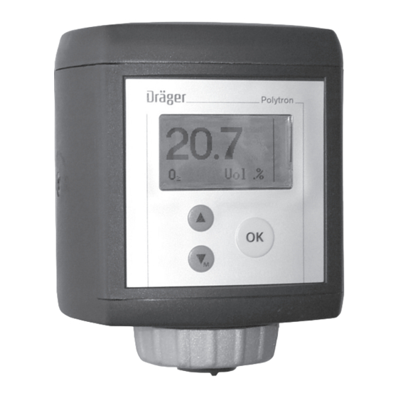
Dräger Polytron 7000
(approved as type P3U and P3FB)
Transmitter for electrochemical Sensors
Instructions for Use
Related Manuals for Dräger Polytron 7000
Summary of Contents for Dräger Polytron 7000
-
Page 1
Dräger Polytron 7000 (approved as type P3U and P3FB) Transmitter for electrochemical Sensors Instructions for Use… -
Page 2: Table Of Contents
…………22 Installing the measuring unit Dräger Polytron 7000 .
-
Page 3
……… . 81 Polytron 7000 Operation via Foundation Fieldbus . -
Page 4: For Your Safety
— If the transmitter is equipped, either when delivered or subsequently, with the relay module and/or the pump module, the complete unit is no longer approved for use in explosion-hazard areas. The use of the Dräger Polytron 7000 equipped with a pump module and/or relay module in explosion-hazard areas is forbidden! Explosion hazard! —…
-
Page 5: Intended Use
Notes on use in zone 22: Valid for all Dräger Polytron 7000 versions without pump and/or relay module (see II 3D identification marking on the identifica- tion tag) and the accessories Duct Adapter for Remote Sensor (Order No. 83 17 150), Remote Sensor (Order No. 83 17 275) and Remote Cable (Order No.
-
Page 6
— Special calibration mode (blocking of alarm triggering, display of calibration mode, one-man calibration). Detection of oxygen in accordance with EN 50104 Attention: If the Dräger Polytron 7000 transmitter is used for the detection of oxygen, at least one alarm relay must be configured as latching. Measuring function for the explosion protection BVS 03 ATEX E 406 X Dräger Polytron 7000 4 to 20 mA… -
Page 7: Design
Caution: This option is only possible without explosion protection approval. Explosion hazard! Attention: If the Dräger Polytron 7000 transmitter is used in connection with the relay module for the detection of oxygen in accordance with EN 50104, the transmitter must be equipped with software version 7.8.
-
Page 8
Design Daisy-chain kit For the connection of several Dräger Polytron 7000 transmitters to one bus line (multidrop installation). This option does not affect the explosion-protection approval of the transmitter. Duct extension For mounting the Polytron 7000 transmitters on a duct. -
Page 9: Installing The Transmitter
In explosion-hazard areas: Observe the national regulations concerning electrical equipment in explosion-hazard areas. The Dräger Polytron 7000 transmitter consists of several components: — Dräger docking station This can be pre-installed anywhere and contains the electrical installation compo- nents.
-
Page 10: Installing The Docking Station
Installing the transmitter Installing the docking station — If the transmitter is to be installed in a Zone 2 explosion-hazard area, select a lo- cation with low exposure to mechanical risk. — Docking station is installed vertically (transmitter with sensor facing down) in an area with low vibrations and stable temperatures –…
-
Page 11: Electrical Connections
Connecting to the central unit Connect shield to earth of central unit (e.g. housing, earth bar, etc.). Connecting the Dräger Polytron 7000 transmitter to a Dräger control unit (such as Regard, QuadGard, Unigard or Polytron): — Further information about the connection can be found in the instructions for the Dräger control unit.
-
Page 12
Electrical connections Installing the transmitter in areas subject to explosion hazards of zone 0, 1 or Div. 1 Install a safety barrier with the appropriate explosion protection approval (catego- ry 1, 2 or Div. 1) between the transmitter and the control unit. ) ≤30 —… -
Page 13
Electrical connections The maximum possible cable lengths can be found in the table on page 18. In each case, use the line marked «Number of transmitters = 1». — Connect shielding to earth point and/or 0 V (Ex i). Explosion-hazard area, zone 0, 1 or Div. 1 Non-explosion-hazard area 4 … -
Page 14
Connect cable: 1 Use a 4-pole terminal block (X7), Part No. 83 16 268, for the Dräger Polytron 7000 – Observe the polarity of the connections. Cut excess wires short or 2 secure them in center terminals (Part No. 83 16 422). -
Page 15: 3-Wire Connection
20 V. This must be taken into account when determining the maximum cable length (see the table on page 19). — Unigard is not suitable for the connection of a Polytron 7000 transmitter equipped with a relay or pump module.
-
Page 16
Electrical connections Connecting the Dräger Polytron 7000 transmitter to control units with a 4 to 20 mA interfaced made by other manufacturers: — Further information about the connection can be found in the instructions for the control unit being used. -
Page 17: Connections Between Several Transmitters And A Control Unit With Hart Multidrop Connections
Electrical connections Connections between several transmitters and a control unit with HART multidrop connections Each transmitter must first be put into service separately. Use the menu item «Poll- ing Address» to assign a different polling address in the range «1» to «15» to each transmitter which is to be connected to the multidrop cable (see page 69).
-
Page 18
Electrical connections The following tables show permissible combinations of transmitters, supply volt- ages and maximum possible cable lengths. — The capacitance values are typical values for commercially available shielded ca- bles with PVC insulation. The use of cables with different capacity values will re- sult in other cable lengths. -
Page 19
Electrical connections Installing the transmitters in explosion-hazard areas of zone 2 or 22 without a safety barrier — Use only supply units of the device category 3. For safety reasons, we recommend that not more than 8 transmitters be connect- ed to a 2-wire or 3-wire cable. -
Page 20
Electrical connections Maximum cable length with a load resistance of 250 Minimum Number of transmit- 0.5 mm 0.75 mm 1.5 mm 2.5 mm supply voltage ters 265 pF/m 320 pF/m 375 pF/m 400 pF/m 758 m 676 m 612 m 586 m 722 m 645 m… -
Page 21
Electrical connections Maximum cable length with a load resistance of not more than 500 Minimum Maximum possi- Number of 0.5 mm 0.75 mm 1.5 mm 2.5 mm supply voltage transmitters 265 pF/m 320 pF/m 375 pF/m 400 pF/m flow-rate 233 m 349 m 699 m 792 m… -
Page 22: 4-Wire Connection
— Connection to central device with at least 4-wire cable, 0.5 (AWG 20) to 2.5 mm (AWG 13). Installing the LON Communication on the transmitter — For installation using LON communication up to 63 Polytron 7000 can be con- nected to a four wire cable in any configuration including bus, star, loop and mixed.
-
Page 23
(approx. 80 mm). Shorten the shield (if installed) to prevent short-circuiting. Connect cable: 1 4-pin terminal block for Dräger Polytron 7000, observing the polarity. 2 4-pin terminal block for Dräger Polytron 7000, observing the polarity. Slide connecting terminal back into holder. -
Page 24: Installing The Measuring Unit Dräger Polytron 7000
Electrical connections Installing the measuring unit Dräger Polytron 7000 Remove the rain cover from the previously installed docking station. Examine seal for signs of dirt and clean if necessary. 1 Check position of eccentric catches and correct if necessary. The eccentric opening must point upwards, engaged position.
-
Page 25: Fitting The Sensor
Electrical connections Fitting the sensor 1 Remove bayonet ring from transmitter, remove dummy plate. Remove sensor from packaging. Remove the short-circuit strap from the sensor (if it is fitted). Polytron There is a coded connector on the back of the sensor. Place the sensor in the opening with the connector at the back and the Dräger logo at the front.
-
Page 26: Installing Accessories
Installing accessories Installing accessories Various accessories are available for the Dräger Polytron 7000 transmitter and may also be installed later. Daisy chain kit – Cable Entry Kit Intended use Daisy chain kit – 83 17 282: — For the connection of several transmitters to one bus cable (daisy chain or multi-…
-
Page 27: Remote Sensor
— For installation of the sensor at a distance of up to 30 m from the Polytron 7000 transmitter. Remote Cable + Sensor plug 5 m Polytron 7000 – 83 17 270Remote Cable + Sen- sor adapter, 15 m Polytron 7000 – 83 17 998, Remote Cable + Sensor plug 30 m Polytron 7000 –…
-
Page 28: Duct Adapter For Remote Sensor
4 Connect the plug of the Remote Cable (cable length 5, 15 or 30 m) to the remote sensor adapter and secure it by turning the ring clockwise. 5 Insert the sensor plug in the opening on the Dräger Polytron 7000 transmitter with the «Dräger» logo pointing to the front.
-
Page 29: Dräger Polytron 7000 Software Dongles
Install the remote sensor again. Dräger Polytron 7000 software dongles Intended use Dräger Polytron 7000 software dongle – 83 17 618, 83 17 619 or 83 17 860: — For activating additional functions in the Dräger Polytron 7000: Data Dongle —…
-
Page 30
Installing accessories 3 Bend the snap-hooks on the cover of the measuring unit slightly outwards to re- lease them. 4 Remove the cover. Polytron 5 Hold the dongle with the «Dräger» logo pointing towards the measuring unit. Then insert the dongle into any of the three slots. Up to three dongles may be installed simultaneously. -
Page 31: Relay Module
The user must ensure that no related approval markings are left on the Poly- tron 7000. The explosion-protection markings has to be removed from the transmitter. The use of the Polytron 7000 with a pump module and/or relay module installed is not permitted in explosion-hazard areas! Explosion hazard! Note: For operation with the relay module, the transmitter must have a 3-wire con- nection to the control unit.
-
Page 32
Installing accessories After connecting the relay module to the measuring unit: 6 Fit the cover again. Polytron Mounting the measuring unit with relay module 7 Slide the measuring unit with relay module into the docking station and lower it into position, see page 24. 8 Turn the eccentric catches clockwise with an Allen key to lock the measuring unit ⇒… -
Page 33: Pump Module
Installing accessories Pump module Intended use Pump module – to order: — For drawing measuring gas from a remote site into the Dräger Polytron 7000 transmitter. Caution: If a Polytron 7000 is subsequently equipped with the relay module and/or the pump module, the complete unit loses its explosion-protection approval.
-
Page 34
Installing accessories Installing the pump in the transmitter 1 Bend the snap-hooks on the cover of the measuring unit slightly outwards to re- lease them. Remove the cover. Polytron 2 Plug the pump connecting cable to the terminal strip. 3 Slide the glass tube into the holes on the sides of the case and insert the pump module into its holder. -
Page 35
Installing accessories Installing the sensor and pump adapter Unscrew the bayonet ring from the transmitter and remove the blanking disc. Place the sensor in the opening with the Dräger logo facing the front, and push upwards gently until the connector engages. Polytron 1 Place the fastening ring over the sensor opening. -
Page 36: Start-Up
Start-up Switch on power supply. The transmitter begins its warm-up routine: Pioneering Solutions Polytron 7000 — The software version, the date and the time are displayed. Note: SWversion: 2.4 For the correct operation and functionality it is important to set the date and time.
-
Page 37
— A current between 4 and 20 mA flows through the transmitter during normal op- eration. This current is proportional to the gas concentration. — The Dräger Polytron 7000 transmitter uses various current values to indicate the operational status of the transmitter:… -
Page 38
Start-up The following icons may be displayed on the right side of the display in measur- ing mode in order to indicate the operating status of the unit: A warning exists – see page 53 for information on how warnings are displayed. The information can be retrieved in info mode, see page 39. -
Page 39: Activating Info Mode
Start-up Activating info mode The info mode is used to display information on general unit settings and on the unit status. Polytron Press and hold the » « key (longer than 3 seconds) – information about the units is displayed on several screens. —…
-
Page 40
Start-up If «xx.xx.xx xx:xx» is displayed instead of the date and time, or if an incorrect date and time are displayed: (only after the cock has been reset due to a power failure) Set the date and time, see page 65. Note! If the date and time are not set correctly, some functions (such as calibra- tion) cannot be executed! -
Page 41: Maintenance
Maintenance Maintenance Maintenance intervals Before starting operation: Check the calibration, see page 42. Check the transmission of signals to the control unit and the triggering of alarms, page 73. At regular intervals, to be defined by the person responsible for the gas warning installation: Check the transmission of signals to the control unit and the triggering of alarms, page 73.
-
Page 42: Calibrating The Unit
1 Mount a calibration adapter Part No. 68 06 978 (with two hose connectors) on the Polytron 7000. Vent the test gas leaving the adapter into a fume cupboard or into the open air (with a hose connected to the second connector on the calibration adapter).
-
Page 43
Follow the instructions printed on the calibration flask and enclosed with the test-gas ampoules. For units without a pump: 1 Fit the adapter and calibration bottle to the Polytron 7000. Break the test-gas ampoule inside the calibration flask. Wait until the measured value has settled (see the operating instructions for the sensor for the necessary waiting period). -
Page 44: Setting Up The Unit
(or the Ex area has to be declassified). Explosion hazard! Use only DrägerSensors which are approved for use with the Dräger Polytron 7000 transmitter. In the menu » Settings «, select the submenu » Sensor « and then the function »…
-
Page 45
Further information can be obtained from the relevant local authority and from ap- propriate waste disposal companies. Sensor-diagnosis function This function is active only if the Polytron 7000 is equipped with a sensor diagnosis dongle (Part No. 83 17 860). — Extended sensor self-test function, taking such things as the temperature, gas monitoring and remaining sensitivity into account. -
Page 46: Fault — Cause — Remedy
Fault – Cause – Remedy Fault – Cause – Remedy If the display will not function: Have the transmitter checked by DrägerService. The fault and warning numbers shown in the following tables are displayed in the menu under » Information «, » Instrument «, » Fault « or » Warnings « – see page 53. Fault number Cause Remedy…
-
Page 47
Fault – Cause – Remedy Fault number Cause Remedy # 130 The function » Sensor lock « is active. A Deactivate the function » Sensor lock «, page 76 or use a sensor with a different Part No. has been sensor with the same Part No. -
Page 48: Menu Functions
— from a HART-compatible Hand Held Terminal (HHT), — from a HART-compatible control unit or — from a Polytron 7000 Palm Pilot 515 (non-Ex version) or Palm Pilot 515x Ex version. If the keypad is used, the menus can be operated with the three keys »…
-
Page 49
Menu functions The passwords for the menus » Calibration « and » Settings « can be changed at any time, page 65. Default password settings when the unit leaves the factory: Password for the menu » Calibration «: _ _ _ 1 Password for the menu »… -
Page 50: Basic Operating Procedures
Basic operating procedures Basic operating procedures Switching to quick-menu mode Press the » « for longer than 1 second but less than back to mesure Instrument 3 seconds to open the quick menu. Sensor Datalogger Information on the status and the settings of the transmit- ter can be queried here, see page 52.
-
Page 51: Navigation In The Menu
Basic operating procedures Navigation in the menu Graphical symbols (icons) simplify the navigation through the various menus: Together with the text » Back «, » Menu «, etc. » — Exit from the menu or return to previous menu. Closed folder —…
-
Page 52: The Menu » Information
The menu » Information « The menu » Information « The menu » Information « contains all information about the unit status, the sensors and the Datalogger. Overview Information Information Calibration Instrument Instrument page 53 Settings Sensor Warnings page 54 page 53 Datalogger Faults…
-
Page 53: Submenu » Instrument
The menu » Information « Submenu » Instrument « The submenu » Instrument Info « contains all functions for interrogating the unit status. Warnings — This function displays any existing warnings in clear text with the warning number, see page 47. The icon »…
-
Page 54: Submenu » Sensor
The submenu » Sensor « contains the functions for interrogating the sensor status. Sensor vitality This function is active only if the Polytron 7000 transmitter is equipped with the sen- sor diagnostic dongle, see page 29. — This function displays the remaining sensitivity of the sensor.
-
Page 55: Submenu » Datalogger
The submenu » Datalogger « contains the functions for interrogating the Datalogger. Datalogger status This function is active only if the Polytron 7000 transmitter is equipped with the data dongle 83 17 618, see page 29. — This function displays the status of the Datalogger and the Eventlogger.
-
Page 56: The Menu » Calibration
The menu » Calibration « The menu » Calibration « The menu » Calibration « contains all functions needed for the calibration and adjust- ment of the installed sensor. Notes on handling the calibration gas and calibration accessories can be found in the section «Maintenance»…
-
Page 57: Submenu » Span Cal
The menu » Calibration « Select » Back to menu « and press the » « key. Disconnect the flow of zero gas. Zero-point calibration can be aborted at any time: Use the » « key to move to » Back « and press the » «…
-
Page 58: Autocalibration
The menu » Calibration « If these are correct as displayed: Select » Next « and press the » « key. Disconnect the flow of calibration gas. Attention: An alarm could be triggered in the central unit for as long as the calibration gas concentration is pending! —…
-
Page 59
The menu » Calibration « — The required value and the actual value are now displayed. Disconnect the flow of calibration gas. Attention: An alarm could be triggered in the central unit for as long as the calibration gas concentration is pending! If these are correct as displayed: Select »… -
Page 60: The Menu » Settings
The sensor shown in the overview serves only as an example and may differ from the sensor actually installed in the unit. This menu function can be executed only if the Polytron 7000 transmitter is equipped with the data dongle 83 17 618, see page 29.
-
Page 61: Submenu » Instrument
The menu » Settings « Submenu » Instrument « The submenu » Instrument « can be used to make various instrument settings. Pump This group contains the setting functions for the pump. – Flow fault on/off — This function is used to activate and deactivate the generation of a fault if the pump output is too low (flow fault).
-
Page 62
The menu » Settings « Use the » « and » « keys to set the value in l/min and press the » « key to confirm the setting. Select » Next « and press the » « key. — The function is terminated. –… -
Page 63
The menu » Settings « — The function for setting the self-hold function of the A1 alarm is opened. Select » Latching « or » Non latching « and press the » « key to activate. Select » Next « and press the » «… -
Page 64
If the functions » Disable acknowledgement « and » Alarm setting latching « are combined, an alarm can only be acknowledged by interrupting the power supply of the Polytron 7000 transmitter! Attention: If an alarm has been configured as » Can be acknowledged «, it can also be reset when the alarm condition is fulfilled. -
Page 65
The menu » Settings « – Test fault — This function simulates the fault alarm state for testing purposes. Select the menu items » Settings «, » Instrument «, » Alarm « and » Test fault alarm « in this order, pressing the » «… -
Page 66
The menu » Settings « Time format — This function is used to set the display format for the date and/or time. Select the menu items « Settings «, « Instrument « and « Time format « in this or- der, pressing the »… -
Page 67
The menu » Settings « Function key — This function is used to set the function which is to be activated when the function key (the » « key) is pressed briefly. Default setting: Fault report. Select the menu items » Settings «, » Instrument « and » Function key « in this or- der, pressing the »… -
Page 68
The menu » Settings « SW dongle This group permits the deactivation of individual dongles before they are removed or in the case of a fault in a dongle. A dongle can be reactivated only by restarting the unit. – Data dongle Select the menu items »… -
Page 69: Submenu » Communication
The menu » Settings « Submenu » Communication « The submenu » Communication « permits various settings to by made for the inter- faces. HART interface This group contains the setting functions for the HART interface. – Polling address The polling address configures the transmitter either for the analogue mode (4 to 20 mA) or the multidrop mode.
-
Page 70
The menu » Settings « – Tag The tag may be used to mark a specific transmitter. It can comprise up to 8 alphanumeric characters. It can also serve as an address, in order to read the unique identifier using HART command #11 («Read Unique Identifier associated with Tag»), from the transmitter, even if the polling address is unknown. -
Page 71
The menu » Settings « – Warning interval This function is used to set the interval between the warning signals » « on the analogue interface. Select the menu items » Settings «, » Communication «, » Analogue interface « and »… -
Page 72
The menu » Settings « Note: The » static « signal type is a DC current signal whose current value can be configured (see » Maintenance level «). The » dynamic « signal type is an AC signal with the following characteristic: [mA] –… -
Page 73
The menu » Settings « Test functions for the analogue interface – Test analogue — This function is used to set various currents in the range 3 to 22 mA on the ana- logue interface. Note: These functions may trigger alarms in the control unit! If necessary, the alarms should be disabled in the control unit before using the functions. -
Page 74
— The Neuron ID is displayed. – Service PIN The Polytron 7000 can be commissioned by sending its Neuron ID to the LON net- work with the aid of the function «Service PIN». Select the menu items » Settings «, » Communication «, » LON Interface « and »… -
Page 75: Submenu » Sensor
The menu » Settings « Submenu » Sensor « The submenu » Sensor « can be used to make various settings for the installed sen- sor. Change sensor — This function can be used to change a sensor while the unit is running without sending a fault alarm to the control unit.
-
Page 76
Sensor test This group contains the setting functions for the sensor selftest. These functions can be used only if the Polytron 7000 transmitter is equipped with the Sensor Dongle 83 17 619 or the Sensor Diagnostic Dongle 83 17 860, see page 29. -
Page 77
The menu » Settings « Sensor configuration (using an EC–O sensor as an example): This group contains the setting functions for the sensor. – Gas setting — This function is used to change the settings for the gas to be measured. Select the menu items »… -
Page 78: Submenu » Datalogger
The submenu » Datalogger « permits various settings to be made for the Datalogger and the Eventlogger. These functions are available only if the Polytron 7000 transmitter is equipped with the Data Dongle 83 17 618, see page 29. The contents of the Datalogger or Eventlogger can be evaluated only with the PC software GasVision (Version 5.5 or higher).
-
Page 79
The menu » Settings « – Peak / average — This function can be used to select whether the Datalogger is to save peak or av- erage values. Select the menu items » Settings «, » Datalogger «, » Set Datalogger « and »… -
Page 80
The menu » Settings « – Stack/roll — This function can be used to set the operating mode of the Datalogger and the Eventlogger. Select the menu items » Settings «, » Datalogger «, » Set Datalogger « and » Stack/roll « in this order, pressing the » «… -
Page 81: Polytron 7000 Operation Via Lon
— The orange LED indicates communication with the central controller via LON of LON specific data e.g. sending the Service PIN. — The green LED indicates the correct operation of the Polytron 7000 when it is continuously on. When the green LED flashes it indicates a warning in the Polytron 7000.
-
Page 82: Polytron 7000 Operation Via Profibus Pa
Polytron 7000 Operation via PROFIBUS PA Polytron 7000 Operation via PROFIBUS PA For the Polytron 7000 PROFIBUS PA transmitter, a GSD file and a DD file (for the SIMATIC PDM) are available. For the Polytron 7000, a DTM is also available.
-
Page 83
Polytron 7000 Operation via PROFIBUS PA Uncertain sub-status Value Name Description Bit 5, 4, 3, 2 Non-specific There is no specific reason why the value is uncertain. Used for propagation. Last Usable Value Whatever was writing this value has stopped doing so. (This happens when an input is disconnected by a configurer.) -
Page 84
Polytron 7000 Operation via PROFIBUS PA PROFIBUS PA: Coding of the Physical Block Parameter DIAGNOSIS Octet Mnemonic Description DIA_HW_ELECTR Hardware failure of the electronic DIA_HW_MECH Hardware failure mechanics DIA_TEMP_MOTOR Motor- temperature too high DIA_TEMP_ELECTR Electronic temperature too high DIA_MEM_CHKSUM Memory error… -
Page 85
Polytron 7000 Operation via PROFIBUS PA Foundation Fieldbus: Resource Block and BLOCK_ERR: The block error parameter reflects the error status of associated hardware or Transducer Block software components and directly impacts the correct operation of a block. Block errors will notified as block alarms. -
Page 86: Technical Data
2 x repeatability Ingress protection IP 66 / IP 67, according to EN 60 529 / IEC 529 (NEMA 4) Approvals Polytron 7000 is approved as type P3U and type P3FB. ATEX Device markings in accordance with 94/9/EC — Type P3U…
-
Page 87
Technical Data IECEx – Type P3U: EEx ia IIC T4 (–40 C Ta +65 EEx ia IIC T6 (–40 C Ta +40 IECEx BVS 04 0003 X Power Supply: U = 30 V, I = 0,3 A, P = 700 mW, C = 5 nF, L = 50 μH Year of construction (via serial number) -
Page 88
Technical Data Signal transmission to central unit Analogue — Measured-value signal 4 mA to 20 mA — Drift below zero point 3.8 mA to 4 mA — Full-scale value exceeded 20 mA to 20.5 mA — Unit fault <3.2 mA —… -
Page 89: Relay Module
Technical Data Power consumption (without analogue signal trans- typical 50 mW mission) Cable inlet M20 x 1.5; cable diameter 6 mm (0.24″) to 12 mm (0.47″) Wire cross-section 0.5 mm (AWG 20) to 2.5 mm (AWG 13) Weight approx. 0.9 kg / 2.0 lb, without pump and relay module. Ambient conditions Specifications for the sensor: see sensor data sheet for operation…
-
Page 90: Pump Module
Technical Data Pump module Caution: The pump module is not covered by the explosion protection approvals. Use is not permitted in explosion-hazard areas! Explosion hazard! Supply voltage (DC) — for an output of 0.5 L/min 12 V to 30 V at the transmitter —…
-
Page 91: Order List
Dräger Polytron 7000 4 to 20 mA D with pump module, 83 17 637 with display and keypad Dräger Polytron 7000 4 to 20 mA D with relay and pump mod- 83 17 638 ules, with display and keypad Dräger Polytron 7000 4 to 20 mA HART,…
-
Page 92: Sensors
Order No. Dräger Polytron 7000 LON D, 83 17 810 with display and keypad Dräger Polytron 7000 LON D with relay module, 83 17 816 with display and keypad Dräger Polytron 7000 LON D with pump module, 83 17 817 with display and keypad Dräger Polytron 7000 LON D with relay and…
-
Page 93: Accessories
Dräger Polytron 7000 Data Dongle 83 17 618 Dräger Polytron 7000 Sensor Dongle 83 17 619 Dräger Polytron 7000 Sensor Diagnostic Dongle 83 17 860 Pump adapter for AC sensor used with 68 09 380 83 17 976 Gas Vision…
-
Page 94: Atex Approval
ATEX approval ATEX approval…
-
Page 95
ATEX approval… -
Page 96
ATEX approval… -
Page 97
ATEX approval… -
Page 98
ATEX approval… -
Page 99
ATEX approval… -
Page 100
ATEX approval… -
Page 101
ATEX approval… -
Page 102
ATEX approval… -
Page 103
ATEX approval… -
Page 104: Metrological Certificate Of Approval
Metrological certificate of approval Metrological certificate of approval Neutralization measurements for the explosion protection according to BVS 03 ATEX E 406 X and monitoring of oxygen defi- ciency or excess of oxygen according to EN 50104, PFG No. 41300504. Caution: Not suitable for use in oxygen-enriched atmospheres, i.e.
-
Page 105: Overview Of The Adjustment Ranges
Metrological certificate of approval Overview of the adjustment ranges page Adjustment range Default value Note Calibration gas concentra- 3,750 ppm to 262,500 ppm 209,000 ppm for DrägerSensor O -LS (6809630) tion 2,997 ppm to 1,050,000 ppm 209,000 ppm for DrägerSensor O (6809720) A1 alarm threshold 999 ppm to 250,000 ppm…
-
Page 106: Information On Drägersensor O
Metrological certificate of approval Information on DrägerSensor O (6809720) Principle of measurement: The DrägerSensor O (6809720) is an electrochemical two-electrode-sensor for measurement of oxygen (O in air. The sensor can only be operated in connection with a suitable Dräger transmitter. –…
-
Page 107: Information On Drägersensor O 2 -Ls (6809630)
Metrological certificate of approval Information on DrägerSensor O -LS (6809630) Principle of measurement: The DrägerSensor O -LS (6809630) is an electrochemical three-electrode-sensor for measurement of oxygen ) in air. The sensor can only be operated in connection with a suitable Dräger transmitter. The sensor cannot be used for oxygen measurements in the presence of helium! –…
-
Page 108
Metrological certificate of approval Gas / vapour Chemical symbol Gas concentration Measurement value deviation in Vol.-% with dust filter ethine 1 Vol.-% 0.5 (–) * ethylene oxide 20 ppm 2 (–) * hydrogen fluoride 15 ppm no influence formaldehyde HCHO 40 ppm no influence carbon dioxide… -
Page 109: Iecex Approval
IECEx approval IECEx approval…
-
Page 110
IECEx approval… -
Page 111
IECEx approval… -
Page 112
IECEx approval… -
Page 113
IECEx approval… -
Page 114: Ul Approval
UL approval UL approval…
-
Page 115
UL approval… -
Page 116
UL approval… -
Page 117
UL approval… -
Page 118
UL approval… -
Page 119
UL approval… -
Page 120
UL approval… -
Page 121: Csa — Approval
CSA — Approval CSA — Approval…
-
Page 122
CSA — Approval… -
Page 123
CSA — Approval… -
Page 124
CSA — Approval… -
Page 125
CSA — Approval… -
Page 126: Declaration Of Conformity
Declaration of Conformity Declaration of Conformity…
-
Page 127
Declaration of Conformity… -
Page 128
Declaration of Conformity… -
Page 129: Index
Index Index 2-wire connection ……….. . . 11 3-wire technology .
-
Page 130
Index Datalogger, clearing ……….. 80 Date . -
Page 131
Index Icons …………..38 Identifier . -
Page 132
Index Password for the menu » Settings « ……..49 Password Settings . -
Page 133
The measuring unit Dräger Polytron 7000 ……. . . 9… -
Page 134
Index Warm-up routine …………36 Warning interval . -
Page 135: Drilling Templates
Drilling templates Drilling templates Dräger docking station…
-
Page 137: Remote Sensor
Drilling templates Remote sensor Duct adapter Ø 35 ± 1 mm 94 mm ± 1 mm…
-
Page 140
Dräger Safety AG & Co. KGaA Revalstraße 1 D-23560 Lübeck Germany Tel. +49 451 8 82 — 27 94 Fax +49 451 8 82 — 49 91 www.draeger.com 90 33 002 — GA 4683.100 en © Dräger Safety AG & Co. KGaA edition — 04_2007 Subject to alteration…
This manual is also suitable for:
P3uP3fb
Характеристики
- ТипИскробезопасный датчик газов для электрохимических сенсоров
- Измеряемые газыТоксичные газы и кислород
- Принцип измеренияЭлектрохимический
- Диапазоны измеренияРегулируются пользователем (см. спецификацию сенсора)
- ДисплейБольшой графический дисплей, 34 x 62 мм, 64 x 128 пикселей
- Полнотекстовое представление структуры меню и сообщений, 3-кнопочная навигация
- Статусный индикаторИмеется (модификация со встроенными реле)
- Выходной сигналАналоговый (4–20 мА), Цифровые (HART®, LONWORKS®, PROFIBUS PA, FOUNDATION fieldbus™)
- Напряжение питания16.5–30 В пост. тока; 2-проводное, 3-проводное для насосного модуля и релейного модуля*
- Насосный модуль (опция)*Шланг до 30 м / 100 футов. Расход 0.5 л/мин с внутренним диаметром 4 мм / 3/16”
- Релейный модуль (опция)*Два сигнальных реле, одно реле неисправности, 1-полюсные перекидные, программируются пользователем
- Коммутационная способность 5 А / 240 В пер. тока, 5 А / 24 В пост. тока
- Условия окружающей среды для датчика газов (для сенсоров см. отдельную спецификацию сенсора)
- Температура–60 … +65 °C (согласно сертификату соответствия ТР ТС и его приложениям)
- Давление700–1300 гПа
- Влажность0–100 %, относительная
- Корпус датчика газовСтеклопластик
- Класс защиты корпусаIP 66/67, NEMA 4,
- Кабельный вводМ20
- Размеры (ВхШхГ)166 x 135 x 129 мм
- ВесОколо 900 гр.
- Уровень SILПроверен SIL 2
- Маркировка взрывозащиты (Таможенный союз)0 ExiaIICT4 X
- Электромагнитная совместимостьДиректива 89/336/EEC
- Спецификацию заказа см. в кратком описании или руководстве по эксплуатации.
- * Только для приложений общего назначения. Датчик газов теряет все аттестации, кроме маркировки СЕ, когда используется с LON, насосным или релейным модулем
|
Detail Specifications: 1757/1757366-polytron_7000.pdf file (31 Mar 2023) |
Accompanying Data:
Dräger Polytron 7000 Gas Detectors, Transmitter PDF User Manual Manual (Updated: Friday 31st of March 2023 09:24:00 AM)
Rating: 4.1 (rated by 83 users)
Compatible devices: X-am 1700, X-am 5100, PIR 3000, GasSecure GS01, Polytron 8100, Polytron 3000, PointGard 2100, Regard 3900.
Recommended Documentation:
Text Version of User Manual Manual
(Ocr-Read Summary of Contents, UPD: 31 March 2023)
-
55, Dräger Polytron 7000 ,QVWUXFWLRQVIRUXVH_ Dräger Polytron 7000 Annex 29969 D e s cript ion / Benennung Status / Reifegrad Control Dra w ing CSA ( P3) Kontroll Zeichnung CSA (P 3) Prep Part N o. / Sachnummer – Rev / ÄZ Y SE20106 — 03 Do cume n t Ty pe / D oku m en tent y p T EX T_ DR A WIN G A 3 Page / Se ite 3 of / von 4 R…
-
25, Dräger Polytron 7000 ,QVWUXFWLRQVIRUXVH_ Dräger Polytron 7000 Calibration WARNING Health hazard from test gas Breathing in of test gas can be harmful to health or lead to death. ► Do not inhale the test gas. ► Observe risks connected with the test gas, hazards notes and safety advice (see for example safety data sheets, instructions on the testing media). CAUTION Alarms triggered by test g…
-
30, Dräger Polytron 7000 ,QVWUXFWLRQVIRUXVH_ Dräger Polytron 7000 Troubleshooting 3. Select Next. The current measured value and the gassing time are displayed. 4. Wait until the measured value has stabilised. When the displayed measured value has stabilised (max. wait time = 3 minutes), select calibrate. With some sensors, the gas detector recognises by itself if the mea…
-
33, ,QVWUXFWLRQVIRUXVH_ Dräger Polytron 7000 Maintenance 8 Maintenance 8.1 Preparing a maintenance plan The gas detector must be serviced at regular intervals. The intervals and activities are defined in the maintenance plan by the person who is responsible for the gas detection system. The maintenance interval recommended by Dräger is 6 months. Dräger reco…
-
42, Dräger Polytron 7000 ,QVWUXFWLRQVIRUXVH_ Dräger Polytron 7000 Sensor settings 2. Select Enable or Disable. 11.3.2 Performing the sensor self-test manually 1. Select Settings > Sensor and the menu item for the sensor used. Select Sensor selftest. 2. If a sensor self-test is available (depending on the sensor used and on the device status), select Start Sensortest. 3. Select Confi…
-
43, ,QVWUXFWLRQVIRUXVH_ Dräger Polytron 7000 Data storage setting (only with the data dongle) 3. Select Confirm. 12 Data storage setting (only with the data dongle) The data logger comprises a measured value logger and an event logger. The measured value logger can only be evaluated with the GasVision PC software (Version 5.5 or higher). 12.1 Information about the measu…
-
34, ,QVWUXFWLRQVIRUXVH_ Dräger Polytron 7000 Device settings 9 Device settings 9.1 Pump (only with pump module) 9.1.1 Adjusting the pump output Equipment: – Pump adapter (order no. 8320900) – flowmeter 1. Select Settings > Instrument > Pump > Pump flow. The 4-20 mA interface issues the maintenance signal. «Flowalarm woud be disabled. Please usea…
-
11, ,QVWUXFWLRQVIRUXVH_ Dräger Polytron 7000 Description Power supply: Ui = 30 V, Ii = 0.3 A, Pi = 700 mW, Ci = 5 nF, Li = 50 μH Year of manufacture (via serial number) 1) Dräger Safety, 23560 Lübeck, Germany Type P3U Safety-related characteristic values for the supply and signal circuit (outer terminals of the docking station): Ui = 30 V…
-
13, ,QVWUXFWLRQVIRUXVH_ Dräger Polytron 7000 Use Measurement of oxygen PFG 16 G 005 X The pump module is not part of the EU type examination certificate BVS 03 ATEX E 406 X and the type examination certificate PFG 16 G 005 X. 4 Use In addition to the control panel, the unit can also be operated using, for example, the Dräger PolySoft software, FDT applicatio…
-
15, ,QVWUXFWLRQVIRUXVH_ Dräger Polytron 7000 Use 4.1.3 Meaning of the symbols Symbols on the right side of the displays indicate the device state. Some symbols are only displayed if the gas detector is operated with the corresponding component. 4.1.4 LED indication for LON version The LON version of the gas detector has three LEDs located behind the display. Symb…
Recommended Instructions:
Savvio FC, FastMig KM300, C-VGA-DVI, Spider 275


-
1592039020 XLH210 GB r1.0 Gas Leak Detector 2016.04.26.doc XLH210 1/2 GAS LEAK DETECTOR XLH210 1. GENERAL WARNINGS ………………………………………………………………………………………………………. 1 2. GENERAL DESCRIPTION……………………………………………………………………………………………… …
Dixell XLH210 2
-
GTC-550Instruction ManualHeadquarters / Engineering research laboratory : 23 Gunpo Advance d Industry 1-ro(Bugok-dong), Gunpo-si, Gyeonggi-do Tel +82-31-490-0800 Fax +82-31-490-0801Yeongnam business office / Plant : 55 Gonghangap-gil 85beon-gil, Gangseogu, Busan Metropolitan CityTel +51-973-8518 Fax +51-973-8519E-mail : [email protected] in detail for correc …
GTC-550 20
-
PART. T2420ENONO BIIIP !!BIIIIP!!Premere solo una voltaNur einmal drückenAppuyer une seule foisPress once onlyPulsar sólo una vezSlechts één keer indrukkenNONO BIIIP !!OKBticino5 cm~ 15 secIstruzioni d’usoGebrauchsanweisungenNotice d’emploiInstructions for useInstrucciones de usoGebruiksaanwijzing08/05-01 PCMAX 5Se il rilevatore non va in allarmeWenn der Detektor nicht auf Alarm schal …
AXOLUTE 2
Additional Information:
Popular Right Now:
Operating Impressions, Questions and Answers:
Dräger Manuals and Guides:
The main types of Dräger Polytron 7000 instructions: user guide — rules of useing and characteristics, service manual — repair, diagnostics, maintenance, operation manual — description of the main functions of Dräger Polytron 7000 equipment, etc.
Most of the instructions, that you can see on the site are uploaded by our users. If you have available a manual or document for Dräger Polytron 7000, which is currently not on the site or present in a different language version, we ask you to upload your document on website, using the «uploading form» available to all registered users.