-
Contents
-
Table of Contents
-
Troubleshooting
-
Bookmarks
Quick Links
USER INSTRUCTIONS
Logix
520MD+ and 510+
Installation
®
Digital Positioners
Operation
Maintenance
FCD LGENIM0105-15-AQ – (05/16)
Experience In Motion
Related Manuals for Flowserve Logix 520MD+
Summary of Contents for Flowserve Logix 520MD+
-
Page 1
USER INSTRUCTIONS Logix 520MD+ and 510+ Installation ® Digital Positioners Operation Maintenance FCD LGENIM0105-15-AQ – (05/16) Experience In Motion… -
Page 2: Table Of Contents
Logix 520MD+ and 510+ Digital Positioners FCD LGENIM0105-15-AQ – 05/16 ® Contents 6 Tubing 6.1 Determine Air Action 6.2 Connect Supply Port 6.3 Purging Single Acting Actuators 1 General Information 6.4 Vented Design 1.1 Using This Document 7 Electrical Connections 1.2 Terms Concerning Safety 7.1 Electrical Terminals 1.3 Protective Clothing…
-
Page 3
18.10 Replacing A Single Acting Pilot Relay 19 Troubleshooting 19.1 Troubleshooting Guide 19.2 Status Code Index 19.3 Status Code Descriptions 19.4 Help From Flowserve 20 Positioner Dimensions 20.1 Positioner Dimensions 21 How To Order 21.1 Positioners 21.2 Spare Parts Kits 21.3 Gage Blocks… -
Page 4
Logix 520MD+ and 510+ Digital Positioners FCD LGENIM0105-15-AQ – 05/16 ® Figure 15: Maxflo Assembly Figure 16: Maxflo Connection Figure 17: Automax Bracket Figure 18: Automax Assembly Figure 19: Mounting To A Linear Actuator Figure 20: Linear, Double Acting, Air To Open Figure 21: Rotary, Double Acting, Air To Open Figure 22: Linear, Single Acting, Air To Open Figure 23: Exhaust Vents… -
Page 5: General Information
520MD+ and 510+ Digital Positioners FCD LGENIM0105-15-AQ – 05/16 ® General Information 1.3 Protective Clothing Flowserve positioners use high pressure gas to operate. Use eye 1.1 Using This Document protection when working around pressurized equipment. Follow proper Product users and maintenance personnel should thoroughly review procedures for working with natural gas if it is used.
-
Page 6: Service / Repair
The Logix 500+ receives power from the two-wire, 4-20 mA input Flowserve will not accept deliveries if a certificate has not been signal. However, since this positioner utilizes HART communications, provided (a form can be obtained from Flowserve).
-
Page 7: Command Input And Final Command
The Final Command is compared against the Stem Position. If any deviation exists, the control algorithm sends a signal to the inner-loop control to move the relay in a direction, depending upon the deviation. flowserve.com…
-
Page 8: Detailed Sequence Of Positioner Operations
Logix 520MD+ and 510+ Digital Positioners FCD LGENIM0105-15-AQ – 05/16 ® Assume the input signal changes from 12 mA to 16 mA. The position- er sees this as a command source of 75 percent. With Linear charac- terization, the Final Command becomes 75 percent. Deviation is the difference between Final Command and Stem Position: Deviation = 75% — 50% = +25%, where 50 percent is the present stem position.
-
Page 9: Figure 3: Logix 500+ Digital Positioner Schematic
Pressure Sensor Cable Regulator Assembly Feedback Cable Piezo Cable Exhaust Hall Sensor Cable Port A Auxiliary Card Feedback Potentiometer Main Board Actuator Housing 4-20 mA Input Spring Hall Sensor Assembly Piston Exhaust Stem Port B Yoke Supply Pressure Take-Off Arm flowserve.com…
-
Page 10: Specifications
Logix 520MD+ and 510+ Digital Positioners FCD LGENIM0105-15-AQ – 05/16 ® SPECIFICATIONS 2.3 Air Supply Table 3: Air Supply 2.1 Input Signal Minimum Input Pressure 1.5 Bar (22 PSI) Table 1: Input Signal Maximum Input Pressure Single Acting Relay – 6.2 Bar (90 PSI) Positioner Alone or with Multi-Function Card Double Acting Relay –…
-
Page 11: Stroke Output
NAMUR NC-5 -40 °C to 100 °C Temperature (-40 °F to 212 °F) Load Current 0…100 mA Inductive Sensor Voltage 10…30 VDC P&F NBB2-V3-E2 PNP NO -25 °C to 70 °C Temperature General Purpose Only (-13 °F to 158 °F) flowserve.com…
-
Page 12: Valvesight Dtm Software Specifications
Logix 520MD+ and 510+ Digital Positioners FCD LGENIM0105-15-AQ – 05/16 ® 2.12 ValveSight DTM Software Specifications Table 12: ValveSight DTM Software Specifications Minimum Pentium processor running Windows 2000, XP, Server 2003, Server 2003 R2, Server 2008 (32-bit & 64-bit Computer Versions), Server 2008 R2 (32-bit &…
-
Page 13: Hazardous Area Certifications
Logix 520MD+ and 510+ Digital Positioners FCD LGENIM0105-15-AQ – 05/16 ® HAZARDOUS AREA CERTIFICATIONS DANGER: Certifications listed on the positioner are correct for that positioner. Before using the information on this page, ensure the certifications on the positioner label match the certifications on this page. Table 13: Logix 500+ Series Hazardous Locations Information ATEX North America (cFMus)
-
Page 14: Storage And Unpacking
Verify that the labels match the intended application. 4.1 Storage NOTE: Mark checkbox next to hazardous area information for Flowserve Control valve packages (a control valve and its instrumen- protection method Logix 500MD+ is installed to. tation) are typically well protected from corrosion. Nevertheless Flow- serve products must be stored in a clean, dry environment such as an enclosed building that affords environmental protection.
-
Page 15: Mounting And Installing
Slip the large end of the teardrop shaped mounting hole in the back of the positioner/bracket assembly over the mounting bolt. Slide the small end of the teardrop under the mounting bolt and align the lower mounting hole. Figure 6: Mounting to Mark I Linear Valves flowserve.com…
-
Page 16: Mounting To Flowtop Linear Valves
Logix 520MD+ and 510+ Digital Positioners FCD LGENIM0105-15-AQ – 05/16 ® 5.2 Mounting to FlowTop Linear Valves Assemble the take-off pin to the take-off plate and mount the take-off plate to the valve stem using the two screws. Adjust the To mount a Logix 500+ positioner to a FlowTop linear actuator and follower pin to match the correct location as indicated on the valve (with direct mounting / integrated tubing), refer to Figure 7 and…
-
Page 17: Figure 8: Flowtop Mounting
Optionally, con- tinue to attempt the calibration. Each calibration attempt adjusts the acceptable limits and it should pass eventually. Actuator Screws Actuator O-Ring Take-Off Pin Take-Off Plate Take-Off Plate Screws Figure 8: FlowTop Mounting flowserve.com…
-
Page 18: Mounting To Standard Valtek Rotary Valves
Logix 520MD+ and 510+ Digital Positioners FCD LGENIM0105-15-AQ – 05/16 ® 5.3 Mounting to Standard Valtek Rotary Valves Using a ½” end wrench and two 5/16-18 X ½” bolts, attach bracket to actuator transfer case pad. Leave these bolts slightly The standard rotary mounting applies to Valtek valve/actuator assem- loose until final adjustments are made.
-
Page 19: Figure 12: Valtek Rotary Final Orientation
14. If the calibration was successful the green LED will blink GGGG NOTE: To virtually eliminate non-linearity, use the Linearization or GGGY and the valve will be in control mode. feature on the Custom Characterization page of the DTM. Figure 12: Valtek Rotary Final Orientation flowserve.com…
-
Page 20: Mounting To Maxflo Rotary Valves
Logix 520MD+ and 510+ Digital Positioners FCD LGENIM0105-15-AQ – 05/16 ® 5.4 Mounting to MaxFlo Rotary Valves Slide the take-off arm onto the shaft. Insert the screw with star washer through the take-off arm and add the second star washer and nut.
-
Page 21: Mounting To Rotary Namur (Automax) Valves
See Figure 18. Connect regulated air supply to appropriate port in manifold. See section 6 TUBING. Connect the power to the 4-20 mA terminals. See section 7 ELECTRICAL CONNECTIONS. Remove main cover and locate DIP switches and QUICK-CAL/ ACCEPT button. flowserve.com…
-
Page 22: Figure 17: Automax Bracket
Logix 520MD+ and 510+ Digital Positioners FCD LGENIM0105-15-AQ – 05/16 ® Figure 17: AutoMax Bracket Figure 18: AutoMax Assembly…
-
Page 23: Mounting To A Linear Namur Pneumatic Actuator
Connect the power to the 4-20 mA terminals. See section 7 ELECTRICAL CONNECTIONS. 10. Remove main cover and locate DIP switches and QUICK-CAL/ ACCEPT button. 11. Refer to sticker on main board cover and set DIP switches accordingly. See section 8 STARTUP. flowserve.com…
-
Page 24: Tubing
Logix 520MD+ and 510+ Digital Positioners FCD LGENIM0105-15-AQ – 05/16 ® TUBING After mounting has been completed, tube the positioner to the actu- ator using the appropriate compression fitting connectors. For best performance, use 10 mm (3/8 inch) tubing for 645 square cm (100 square inch) actuators or larger.
-
Page 25: Connect Supply Port
When a single acting relay is used, a special procedure can be performed to configure the positioner to purge properly using port A. Contact your local Flowserve Representative for more information regarding the purging option. 6.4 Vented Design A standard Logix 500+ positioner is vented directly to the atmosphere.
-
Page 26: Figure 24: Pneumatic Connections
Logix 520MD+ and 510+ Digital Positioners FCD LGENIM0105-15-AQ – 05/16 ® Spool Style Spool Style Relay Port Relay Relay (Single Acting) (Double Acting) (Single Acting) Supply Supply Supply (Plug) (Plug) Figure 24: Pneumatic Connections…
-
Page 27: Electrical Connections
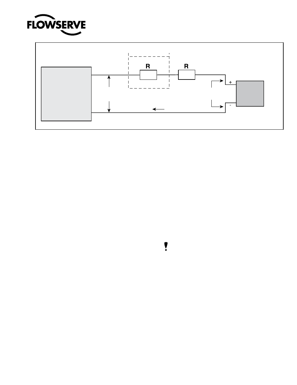
Never connect a voltage source directly across the the calculation in the following equation. The Available Voltage must Logix 500+ terminals. This could cause permanent circuit board be greater than 10VDC in order to support the Logix 500+. Also, see damage. Table 1: Input Signal. flowserve.com…
-
Page 28: Figure 26: Compliance Voltage
The thread size is indicated on the side of the positioner near the conduit connections. Conduit fittings must match equipment housing threads before installation. If threads do not match, obtain suitable adapters or contact a Flowserve representative. See Figure 27: Con- duit and Grounding.
-
Page 29: Multi-Function Card (Ao, Do, Di)
An electromagnetic line filter can be used to further eliminate noise (Flowserve Part Number 10156843). In the event of a severe electrostatic discharge near the positioner, the device should be inspected to ensure correct operability.
-
Page 30: Figure 29: Mfc Discrete Output Circuit
Logix 520MD+ and 510+ Digital Positioners FCD LGENIM0105-15-AQ – 05/16 ® 7.3.2 Discrete Output Table 14: Auxiliary Card Status Card Condition Status Indication For DO function, wire the MFC in series with a 8 to 40 VDC power Multi-Function Card supply, including a method to determine the current such as a resis- Monitoring Position (typical 4-20mA ) Output (mA)
-
Page 31: To I Card Connections
Equation 4 (Supply Voltage-Terminal Voltage) Figure 32: V to I Card Circuit Example Supply Voltage = 24 V Terminal Voltage = 10 V (24-10) = 20 mA Figure 33: V to I Card installed Figure 31: V to I Card flowserve.com…
-
Page 32: Limit Switches
Logix 520MD+ and 510+ Digital Positioners FCD LGENIM0105-15-AQ – 05/16 ® 7.5 Limit Switches Limit switches provide an independent verification of the position of the feedback shaft. Wire the limit switches according to Table 15: Limit Switch Connections. For more information, see Table 7: Limit Switch Specifications on page 11.
-
Page 33: Remote Mount
Table 16: Remote Mount Card Connections Terminal (See Figure 35: Remote Mount Board) From Remote Mount White Black Figure 35: Remote Mount Board 7.7 Connections for Intrinsically Safe Operation See section 3 HAZARDOUS AREA CERTIFICATIONS for entity parameters and control drawing reference. flowserve.com…
-
Page 34: Startup
Logix 520MD+ and 510+ Digital Positioners FCD LGENIM0105-15-AQ – 05/16 ® STARTUP 8.2 Local User Interface Overview The Logix 500+ local user interface allows the user to calibrate, 8.1 Quick Start Instructions configure the basic operation, and tune the response of the positioner Once the positioner is installed, adjusting the DIP switch settings and without additional tools or configurators.
-
Page 35: Configuration Switch Settings
At Closed selection. If the valve closes with a 4 mA signal, the AO will show a 4 mA signal at closed. If the valve closes with a 20 mA signal, the AO will show a 20 mA signal at closed. flowserve.com…
-
Page 36: Stroke Calibration
Logix 520MD+ and 510+ Digital Positioners FCD LGENIM0105-15-AQ – 05/16 ® termine the gains. The gains are then set automatically. After a stroke More More calibration, the positioner is ready to control. Stable Responsive To perform a Quick-Cal, first ensure the Quick Calibration Switch is set to Auto or Jog as appropriate.
-
Page 37: Analog Output (Ao) Calibration
The DTM AO calibration wizard is found here: Configuration / Card Slot 1 (or 2) / Multi-Function Card / Analog Output Calibration. The LCD AO calibration features are found here: Card 1 (or Card 2) / Multi-Function Card / Config/Cal flowserve.com…
-
Page 38: Positioner Functions (No Display Required)
Logix 520MD+ and 510+ Digital Positioners FCD LGENIM0105-15-AQ – 05/16 ® POSITIONER FUNCTIONS NOTE: Once the Multi-Function Card (MFC) type has been con- figured, the type selection will still remain after a factory reset. (No Display Required) CAUTION: Performing a factory reset may result in the inability to operate the valve until reconfigured properly.
-
Page 39: Analog Input Calibration
0.5 mA. To change the Multi-Function Card to the Discrete Output function, hold down both the ,BACK and the Down button for about 3 seconds. The blink code should change to GRYR. Briefly press the .ACCEPT/QUICK-CAL button. flowserve.com…
-
Page 40: Positioner Functions (Lcd Display)
Logix 520MD+ and 510+ Digital Positioners FCD LGENIM0105-15-AQ – 05/16 ® 10 POSITIONER FUNCTIONS Auxiliary Card 1 Status — This shows the type of card in auxiliary card slot 1. Auxiliary Card 2 Status — This shows the type of card in auxiliary card slot 2. (LCD Display) DIP Switch Override –…
-
Page 41: Figure 38: Display Main View
Down buttons to adjust the contrast. Use the (locked), improving the stability of the valve position. The point at .ACCEPT/QUICK-CAL to accept the settings. which the pressure control is locked depends on the Valve Stability Figure 38: Display Main View flowserve.com…
-
Page 42: Menu Overview
Logix 520MD+ and 510+ Digital Positioners FCD LGENIM0105-15-AQ – 05/16 ® 10.2 Menu Overview Temperature Units Status Air Flow Units Command (mA) Actuator Area Units Command (%) Date Format Position (%) Number Format PS (Supply Pressure) LCD Orientation PA (Port A Pressure) Burst Mode PB (Port B Pressure) ON/OFF…
-
Page 43: Menu Features
0.5% as a default, but can be changed using the DTM. Last Result shows “Pass” or “Fail” from the last PST attempt. Valve Travel is counted in small increments every time the valve moves beyond the dead-band window. The travel is displayed in % of full stroke. flowserve.com…
-
Page 44
Logix 520MD+ and 510+ Digital Positioners FCD LGENIM0105-15-AQ – 05/16 ® 10.3.4 Calibration “Set 0%”, set the command input current to 4 mA. (The display will show a low Analog to Digital Count (ADC) that corresponds to 4 mA.) .Calibration Then press the .ACCEPT/QUICK-CAL button to set the value. -
Page 45
(default). With Single selected, the most con- servative gains found during calibration are applied in both the open and closing directions. 10.3.6 Configuration (Characterization) .Configuration .Characterization .MaxFlo Linear .MaxFlo Equal % .Valdisk Linear .Valdisk Equal % .ShearStream Linear .ShearStream Equal % .Custom flowserve.com… -
Page 46: Figure 39: Characterization Curves
Logix 520MD+ and 510+ Digital Positioners FCD LGENIM0105-15-AQ – 05/16 ® Table 19: Characteristic Curve Data Final Command Characterization Characterization DIP set to “Other” DIP set to “Linear” Command Custom Input Shear-Stream Linear MaxFlo Linear MaxFlo =% Valdisk Linear Valdisk =% Shearstream=% (Default) Linear…
-
Page 47
The clock does not account for daylight savings. Set Time and Date – Use the Up and Down buttons to set the time and date. The format of the time and date is displayed above the input fields. flowserve.com… -
Page 48
Logix 520MD+ and 510+ Digital Positioners FCD LGENIM0105-15-AQ – 05/16 ® 10.3.11 Configuration (Burst Mode) CAUTION: Performing a factory reset may result in the inability to operate the valve until reconfigured properly. Notify proper .Configuration .Burst Mode personnel that the valve may stroke, and make sure the valve is .On/Off properly isolated. -
Page 49: Hart Communication
“Set 100%” current. on-line diagnostic tests, calibrations and system configurations. If Set As DO Card The ValveSight DTM is available from a Flowserve representative or Use DTM – The DO is highly configurable. Use the ValveSight DTM from www.valvesight.com.
-
Page 50: Burst Mode
Logix 520MD+ and 510+ Digital Positioners FCD LGENIM0105-15-AQ – 05/16 ® 11.4 Burst Mode CAUTION: Observe precautions for handling electrostatically sensitive devices. Burst Mode is available with a handheld device. In the handheld, se- lect the Burst Mode feature under the Configuration Menu. Variables With a clean, non-conductive instrument, change the position that are transmitted in burst mode are shown in the table below.
-
Page 51: Model Features
• The “Advanced” DTM provides a view of the positioner’s full health analysis and interfaces to all of the positioner’s “Pro” diagnostic functionality. It is generally wise to use the Advanced DTM with the Advanced and Pro positioners. flowserve.com…
-
Page 52: Multi-Function Card
Logix 520MD+ and 510+ Digital Positioners FCD LGENIM0105-15-AQ – 05/16 ® 13 MULTI-FUNCTION CARD 13.2 Discrete Output (DO) Use the Discrete Output function of the MFC to indicate a variety of The optional Multi-Function Card (MFC) can be configured to act as conditions such as alarms, warnings, position limits, etc.
-
Page 53: To I Card
Electronic Specifications 2.7 Limit Switch Specifications Certifications Hazardous Area Certifications Electronic Connections 7.5 Limit Switches Install or Adjust the Limit Switch 18.4 Installing a Limit Switch Ordering Limit Switches 21.2 Spare Parts Kits Figure 43: V to I Card flowserve.com…
-
Page 54: Remote Mount
Logix 520MD+ and 510+ Digital Positioners FCD LGENIM0105-15-AQ – 05/16 ® 16 REMOTE MOUNT 16.1 Remote Mount Operation Terminals The remote mount option can be used where excessive vibration or environmental factors prevent the placement of a positioner directly on the valve. The remote mount unit consists of just the feedback mechanism enclosed in a sturdy container.
-
Page 55: Requirements For Safety Integrity
NOTE: If using the V to I card, less than 10 Volts at the V to I card terminals will produce a current less than 3.6 mA. The Flowserve 520MD+ Valve Positioner covered by this safety manual 17.3 Fail Safe State Response Time…
-
Page 56: Lifetime Limits
10 years. The reliability data listed the FMEDA report is only valid Steps for Proof Test for this period. The failure rates of the Flowserve 520MD+ Valve Posi- tioner may increase sometime after this period. Reliability calculations Step Action…
-
Page 57: Maintenance And Repair
0.56 N-m (5 in-lb) Double Acting Relay manifold (2 Screws) 0.56 N-m (5 in-lb) Single Acting Relay (2 Screws) 0.56 N-m (5 in-lb) Main PCB, MFC, V to I & Limit switch terminal 0.5 – 0.6 N-m (4-5 in-lb) connections. flowserve.com…
-
Page 58: Figure 47: Limit Switch
Logix 520MD+ and 510+ Digital Positioners FCD LGENIM0105-15-AQ – 05/16 ® Figure 47: Limit Switch…
-
Page 59: Replacing The Lcd Board
Connect the card to the main board using the internal connector cable. Ensure the connector’s locking features engage. Gently slide the card(s) into the slot(s). CAUTION: Ensure proper circuitry is used before connecting cables to the auxiliary card. See section 7 ELECTRICAL CONNECTIONS for more information. flowserve.com…
-
Page 60: Figure 50: Auxiliary Card
Logix 520MD+ and 510+ Digital Positioners FCD LGENIM0105-15-AQ – 05/16 ® Route the external cable through the electrical conduit ports in the base and connect the external cable to the auxiliary card. See Figure 42: Multi-Function Card. Replace the auxiliary card clips. 10.
-
Page 61: Replacing A Main Board
Replace the inner cover by inserting the 6 retaining screws. To keep the calibration values even after a Factory Reset, write a Calibrate. 1 to Variable 104. Pressure Main Sensor Board Screws Screws Figure 53: Pressure Sensor Board Figure 51: Main Board Screws flowserve.com…
-
Page 62: Cleaning And Replacing A Double Acting Pilot Relay
Logix 520MD+ and 510+ Digital Positioners FCD LGENIM0105-15-AQ – 05/16 ® 18.9 Cleaning & Replacing a Double Acting Pilot Relay Removal Remove the Main Board. See procedure above. Fully loosen the 2 spool block screws. By squeezing the two screws toward each other, grip the spool block and pull it straight out.
-
Page 63: Replacing A Single Acting Pilot Relay
Remove the Manifold gasket. Installation Place the Manifold gasket. Place the supply plug O-ring and screw. Figure 55: Double Acting Relay Assembly Place the single acting relay. Place the two relay assembly screws. Reassemble the main board and covers and calibrate. flowserve.com…
-
Page 64: Figure 57: Single Acting Relay Assembly
Logix 520MD+ and 510+ Digital Positioners FCD LGENIM0105-15-AQ – 05/16 ® Relay Assembly Screws (2) Single Acting Relay Supply Plug Screw & O-Ring Manifold Gasket Base Figure 57: Single Acting Relay Assembly…
-
Page 65: Troubleshooting
Spool valve is corroded or dirty. recalibrate. Disassemble and clean spool valve The backlight uses any residual power not used by Fluctuations in the LCD backlight are normal. No action LCD backlight flickering or dim. other functions of the circuitry. required. flowserve.com…
-
Page 66
Logix 520MD+ and 510+ Digital Positioners FCD LGENIM0105-15-AQ – 05/16 ® 19.2 Status Code Index NOTE: Not all status codes are available with all positioner models. Table 28: Status Code Index Description Status Code Feedback Cal Error RGGY Psn Amplitude WRN YGYY A/O Cal in Prog GRGY… -
Page 67: Status Code Index
4-20 mA signal by using a handheld, the Dashboard page of the DTM, or performing a manual Command Reset. Perform the Com- mand Reset by holding both the UP and DOWN buttons and briefly pressing the QUICK-CAL/ACCEPT button. flowserve.com…
-
Page 68
Logix 520MD+ and 510+ Digital Positioners FCD LGENIM0105-15-AQ – 05/16 ® ..GYYY GRGR FRICTION CALIBRATION REQUIRED DI COMMAND OVERRIDE Description: No friction calibration has been performed since the last Description: The Multi-Function Card has been configured as a Discrete factory reset. -
Page 69
This could mean the control loop has larger calibration. swings or is oscillating faster than desirable. Possible Solutions: Verify the limits are set at an appropriate level. Re- view the control loop parameters and equipment. Adjust as necessary. flowserve.com… -
Page 70
Logix 520MD+ and 510+ Digital Positioners FCD LGENIM0105-15-AQ – 05/16 ® ..YYGR YYRG SUPPLY PRESSURE HIGH WARNING SOFTWARE ERROR WARNING Description: The supply pressure is above the user set warning limit. Description: There has been a watch dog time out, stack overflow Supply pressure that exceeds the maximum rating on the actuator can warning, or CPU usage warning. -
Page 71
Possible Solutions: Recalibrate making sure to use valid command could be caused by rapidly power cycling the positioner. signal values. Possible Solutions: The battery is not replaceable. Verify or reset the time and date. Replace the main board if the problem persists for several days. flowserve.com… -
Page 72
Logix 520MD+ and 510+ Digital Positioners FCD LGENIM0105-15-AQ – 05/16 ® ..RGGY RGYR POSITION RANGE TOO SMALL ANALOG OUTPUT RANGE TOO SMALL POSITION SENSOR ABOVE ADC RANGE Description: During an Analog Output Calibration the difference POSITION SENSOR BELOW ADC RANGE between the milliamp signal at 0% and the milliamp signal at 100% Description: During calibration, the range of motion of the position was too small. -
Page 73
RYRG POSITION SENSOR FAILURE ALARM Description: The feedback arm may be disconnected from the valve assembly or the sensor has failed. Possible Solutions: Check the feedback arm linkage. Recalibrate. If the problem persists return the unit for repair. flowserve.com… -
Page 74
Logix 520MD+ and 510+ Digital Positioners FCD LGENIM0105-15-AQ – 05/16 ® ..RYRY RRGR PRESSURE SENSOR BOARD FAILURE WARNING FRICTION HIGH ALARM Description: One or more pressure sensors may have failed. Description: The valve and actuator friction has passed the user set limit. -
Page 75
Possible Solutions: Review active alarms and warnings to find root causes of this alarm. The deviation settings can be changed in the Valve Health page of the DTM. flowserve.com… -
Page 76: Help From Flowserve
Logix 520MD+ and 510+ Digital Positioners FCD LGENIM0105-15-AQ – 05/16 ® 19.4 Help From Flowserve 19.4.1 Phone Support Over-the-phone troubleshooting is often available for positioner is- sues. Should your positioner be experiencing problems, or if you have questions that are not answered by this manual, feel free to call your local sales representative or a Quick Response Center (QRC).
-
Page 77: Positioner Dimensions
Logix 520MD+ and 510+ Digital Positioners FCD LGENIM0105-15-AQ – 05/16 ® 20 Positioner Dimensions 20.1 Positioner Dimensions flowserve.com…
-
Page 78: How To Order
Logix 520MD+ and 510+ Digital Positioners FCD LGENIM0105-15-AQ – 05/16 ® 21 HOW TO ORDER 21.1 Positioners Table 29: 500+ Positioner Configurations Selection Description Code Example Base Model Logix 500+ Series Analog Only; 8-DIP Set-Up with LCD Option; Limited Diagnostics Communication HART;…
-
Page 79
MFC for 510+ in slot 1 only. This MFC may be configured as AO or DO with limited functionality. Only available with LCD option. When limit switch codes 3, 4 and 5 are selected, only certification codes 14 and 42 should be used flowserve.com… -
Page 80: Spare Parts Kits
Logix 520MD+ and 510+ Digital Positioners FCD LGENIM0105-15-AQ – 05/16 ® 21.2 Spare Parts Kits Table 29: Spare Parts Kits Ref. Description Part-no. Cover: Yellow 283450.999.000 Black 283451.999.000 White 283452.999.000 Board: 505+ Main 331625.999.000 520MD+ Main 283453.999.000 283454.999.000 Pressure Sensor 283455.999.000 Multi-Function Card (Slot1) 283456.999.000…
-
Page 81: Gage Blocks
307321.999.000 Acting 325218.999.000 Poppet Poppet Single Single (kg/cm2) Acting 325208.999.000 (kg/cm2) Acting 325219.999.000 Spool Spool Double Double Acting 291763.999.000 Acting 325220.999.000 Spool Spool UCC Pressure Test Plug 325211.999.000 UCC Pressure Test Plug 325221.999.000 Schrader 645A 325212.999.000 Schrader 645A 325222.999.000 flowserve.com…
-
Page 82: Vdi/Vde 3847 Mounting Blocks
Logix 520MD+ and 510+ Digital Positioners FCD LGENIM0105-15-AQ – 05/16 ® 21.4 VDI/VDE 3847 Mounting Blocks Table 32: VDI/VDE 3847 Mounting Block (Aluminum) Relay Gage Internal Pressure Units Part-no. Type Gages Material Poppet 307308.999.000 Poppet Brass PSI (Bar/kPa) 307309.999.000 Poppet Brass PSI (kg/cm2) 307310.999.000…
-
Page 83
Version Numbers · 38, 48 73, 74 Pressure Sensor Board · 61 Handheld Communicator · 49 Quick Calibration Switch · 36 HART · 5, 6, 10, 12, 41, 48, 49, 56 Quick-Cal · 34 Hazardous Area Certifications · 13 flowserve.com… -
Page 84
Flowserve Corporation has established industry leadership in the design and manufacture of its products. When properly selected, this Flowserve product is designed to perform its intended function safely during its useful life. However, the purchaser or user of Flowserve products should be aware that Flowserve products might be used in numerous applications under a wide India 560 066 variety of industrial service conditions.
Download
Table of Contents
Add to my manuals
Share
URL of this page:
HTML Link:
Bookmark this page
Manual will be automatically added to «My Manuals»
Print this page
- Manuals
- Brands
- Flowserve Manuals
- Valve Positioners
- Logix 520MD+
- User instructions
Digital positioners
Hide thumbs
Also See for Logix 520MD+:
- User instructions (56 pages)
1
Table Of Contents
2
3
4
5
6
7
8
9
10
11
12
13
14
15
16
17
18
19
20
21
22
23
24
25
26
27
28
29
30
31
32
33
34
35
36
37
38
39
40
41
42
43
44
45
46
47
48
49
50
51
52
53
54
55
56
57
58
59
60
61
62
63
64
65
66
67
68
69
70
71
72
73
74
75
76
77
78
79
80
81
82
83
84
-
page
of
84/
84 -
Contents
-
Table of Contents
-
Troubleshooting
-
Bookmarks
Table of Contents
Advertisement
16 Remote Mount
16.1 Remote Mount Operation
17 Requirements For Safety Integrity
17.1F AIL Safe State
17.2 Safety Function
17.3 Fail Safe State Response Time
17.4 Positioner Model Selection And Specification
17.5 Installation
17.6 Required Configuration Settings
17.7 Maximum Achievable SIL
17.8 Reliability Data
17.9 Lifetime Limits
17.10 Proof Testing
17.11 Maintenance
17.12 Repair And Replacement
17.13 Training Requirements
18 Maintenance And Repair
18.1 Scheduled Maintenance
18.2 Required Tools And Equipment
18.3 Torque Specification For Screws
18.4 Installing A Limit Switch
18.5 Replacing The LCD Board
18.6 Replacing An Auxiliary Card
18.7 Replacing A Main Board
18.8 Replacing The Pressure Sensor Board
18.9 Cleaning And Replacing A Double Acting Pilot Relay
18.10 Replacing A Single Acting Pilot Relay
19 Troubleshooting
19.1 Troubleshooting Guide
19.2 Status Code Index
19.3 Status Code Descriptions
19.4 Help From Flowserve
20 Positioner Dimensions
20.1 Positioner Dimensions
21 How To Order
21.1 Positioners
21.2 Spare Parts Kits
21.3 Gage Blocks
21.4 VDI/VDE 3847 Mounting Blocks
21.5 Mounting Kits
Logix
520MD+ and 510+ Digital Positioners FCD LGENIM0105-15-AQ — 05/16
®
54
54
55
55
55
55
55
55
55
55
55
56
56
56
56
56
57
57
57
57
57
59
59
61
61
62
63
65
65
67
68
76
77
77
78
78
80
81
82
82
3
flowserve.com
Table of Contents
Previous Page
Next Page
- 1
- 2
- 3
- 4
- 5
- 6
- 7
Advertisement
Table of Contents
Related Manuals for Flowserve Logix 520MD+
-

Valve Positioners Flowserve Logix 520MD Plus Series User Instructions
Digital positioner (56 pages)
-
Valve Positioners Flowserve Logix 520si Series User Instructions
Digital (20 pages)
-
Valve Positioners Flowserve Logix 520MD Series User Instruction
Digital positioner (19 pages)
-
Valve Positioners Flowserve Logix 3000MD Series Technical Bulletin
Digital positioner (16 pages)
-
Valve Positioners Flowserve Logix 500 Series Installation, Operation & Maintenance Instructions Manual
Digital positioner (20 pages)
-
Valve Positioners Flowserve Logix 3200MD Plus User Instructions
Digital, md series (61 pages)
-
Valve Positioners Flowserve Logix 3400MD User Instructions
Digital (52 pages)
-
Valve Positioners Flowserve Logix 3200MD Installation, Operation And Maintenance Manual
Digital positioner (39 pages)


-
Valve Positioners Flowserve Logix 3200IQ Technical Bulletin
Digital positioner (12 pages)
-
Valve Positioners Flowserve Logix 3200MD User Instructions
Digital positioner (40 pages)
-
Valve Positioners Flowserve Logix 420 User Instructions
Digital positioner (44 pages)
-
Valve Positioners Flowserve APEX 8000 Series Installation Operation & Maintenance
Automax valve automation systems.high-performance positioner (15 pages)
-
Valve Positioners Flowserve APEX 7000 User Instructions
Automax valve automation systems, pneumatic positioner (11 pages)
-
Valve Positioners Flowserve P4 User Instructions
Pneumatic positioners (34 pages)
-
Valve Positioners Flowserve PMV D20 Installation Operation & Maintenance
Digital positioner (34 pages)


Related Products for Flowserve Logix 520MD+
- Flowserve Logix 520si Series
- Flowserve Logix 520MD Series
- Flowserve Logix 3200MD Plus
- Flowserve Logix 3400MD
- Flowserve Logix 3200MD
- Flowserve Logix 3200IQ
- Flowserve Logix 3000MD Series
- Flowserve Logix 500 Series
- Flowserve Logix 520 Series
- Flowserve Logix 420
- Flowserve Worcester 529 Series
- Flowserve Worcester 520 Series
- Flowserve Worcester V-Flow 52 Series
- Flowserve Logix 510si
- Flowserve Worcester 519 Series
- Flowserve Worcester 55 Series
This manual is also suitable for:
Logix 510+
Table of Contents
Питание вкючено
Режим отсечки по минимальному положению (герметичная отсечка)
Местный интерфейс блокирован
Режим управления клапаном по командам цифрового интерфейса (HART)
Производится инициализация
Контрольный режим
Внутреннее ПО блокирует помещение затвора клапана за установленное максимальное положение
Внутреннее ПО блокирует помещение затвора клапана за установленное минимальное положение
Требуется калибровка управляющего давления
Требуется калибровка силы трения
Сигнализация о необходимости проведения проверки неполного хода в соответствии с графиком предварительно установленным пользователем
Выполняется снятие характеристики и проверки неполного хода
Выполняется снятие характеристики и проверки неполного хода
Выполняется калибровка хода
Выполняется калибровка управляющего давления
Выполняется калибровка силы трения
Выполняется калибровка аналогового выхода
Выполняется калибровка входного командного сигнала внутреннего контура управления
Приоритетная команда на дискретном входе
Режим ручного управления
Когда в процессе ручной калибровки появится данная световая индикация, с помощью кнопок ▼ и ▲ установите затвор клапана в полностью открытое
положение. Для подтверждения нажмите на кнопку QUICK-CAL/ACCEPT
Затвор клапана достиг установленного максимального положения или перешел за него
Затвор клапана достиг установленного минимального положения иперешел за него
Превышено предельное количество циклов работы привода
Превышен предельный суммарный ход привода
Превышено предельное количество циклов работы сильфона
Превышен предельный суммарный ход сильфона
Превышено предельное количество циклов работы управляющего пневмораспределителя
Превышен предельный суммарный ход управляющего пневмораспределителя
Превышено предельное количество циклов работы клапана
Превышен предельный суммарный ход клапана
Предупредительная сигнализация — большая амплитуда изменения сигнала положения
Предупредительная сигнализация — высокая частота изменения сигнала положения
Предупредительная сигнализация — большая амплитуда изменения командного сигнала
Предупредительная сигнализация — высокая частота изменения командного сигнала
Сбой проверки работоспособности клапана (проверка заключается в выполнении малых перемещений от текущего положения)
Сбой проверки неполного хода
Температура выше допустимой
Температура ниже допустимой
Затвор клапана перешел за положение «закрыто», установленное при последней калибровке
Затвор клапана перешел за положение «открыто», установленное при последней калибровке
Предупредительная сигнализация — высокое давление питающего воздуха
Предупредительная сигнализация — низкое давление питающего воздуха
Развиваемого приводом усилия недостаточно для управления клапаном
Ошибка памяти
Ошибка программного обеспечения
Повышенная влажность питающего воздуха
Обледенение в системе питающего воздуха
Предупредительная сигнализация — некорректная работа управляющего пневмораспределителя
Предупредительная сигнализация — усилие трения ниже допустимого значениz
Предупредительная сигнализация — усиление трения выше допустимого значения
Предупредительная сигнализация — большой люфт в соединениях
Утечка воздуха в пневматической системе
Аккумулятор разряжен
Предупредительная сигнализация — высокое напряжение на пьезопреобразователе
Предупредительная сигнализация — низкое напряжение на пьезопреобразователе
Усилия пружин привода недостаточно для установки затвора клапана в положении безопасности
Командный сигнал внутреннего контура управления ниже рабочего диапазона аналого-цифрового преобразователя
Командный сигнал внутреннего контура управления выше рабочего диапазона аналого-цифрового преобразователя
Недостаточный диапазон изменения командного входного сигнала внутреннего контура управления
Недостаточный диапазон перемещения рычага обратной связи
Сигнал датчика положения выше рабочего диапазона аналого-цифрового преобразователя
Сигнал датчика положения ниже рабочего диапазона аналого-цифрового преобразователя
Истекло время стабилизации сигнала внутреннего контура
Истекло время стабилизации сигнала датчика положения
Истекло время ожидания перемещения привода
Недостаточный диапазон изменения выходного аналогового сигнала
Требуется калибровка хода
Сместился диапазон сигнала датчика положения по сравнению с последней калибровкой
Диапазон сигнала датчика положения уменьшился по сравнению с последней калибровкой
Диапазон сигнала датчика положения увеличился по сравнению с последней калибровкой
Восстановлены заводские установки. Выполните настройку позиционера и калибровку хода
Аварийная сигнализация — клапан невозможно открыть
Аварийная сигнализация — клапан невозможно закрыть
Аварийная сигнализация — большая амплитуда изменения командного сигнала
Аварийная сигнализация — высокая частота изменения командного сигнала
Аварийная сигнализация — большая амплитуда изменения сигнала положения
Аварийная сигнализация — высокая частота изменения сигнала положения
Аварийная сигнализация — низкое давление питающего воздуха
Ошибка вспомогательной платы 2
Отказ вспомогательной платы 2
Отсутствует питание вспомогательной платы 2
Ошибка вспомогательной платы 1
Отказ вспомогательной платы 1
Отсутствует питание вспомогательной платы 1
Аварийная сигнализация — отказ датчика положения
Отказ датчиков давления
Отказ блока электроники
Аварийная сигнализация — отказ управляющего пневмораспределителя
Аварийная сигнализация — усилие трения ниже допустимого значения
Аварийная сигнализация — усилие трения выше допустимого значения
Аварийная сигнализация — отказ механизма обратной связи
Аварийная сигнализация — большой люфт в соединениях
Аварийная сигнализация — отказ задающего модуля
Аварийная сигнализация — высокое напряжение на пьезопреобразователе
Аварийная сигнализация — низкое напряжение на пьезопреобразователе
Аварийная сигнализация — недопустимое отклонение от заданного положения
|
Detail Specifications: 918/918765-logix_520md_plus_series.pdf file (06 Feb 2023) |
Accompanying Data:
Flowserve Logix 520MD+ Valve Positioners PDF User Instructions (Updated: Monday 6th of February 2023 09:51:23 PM)
Rating: 4.8 (rated by 84 users)
Compatible devices: P4, Logix 520MD Series, PMV D20, Logix 500 Series, D30, Logix 3200MD Plus, XL90 Series, P3 Series.
Recommended Documentation:
Text Version of User Instructions
(Ocr-Read Summary of Contents, UPD: 06 February 2023)
-
38, Flowserve Logix 520MD+ User Instructions — Logix® 520MD+ Series Digital Positioner FCD LGENIM0105-00 © Flowserve Corporation 38 Field Trial Version – Printed October 28, 2011 16.3 Replacing the LCD Board The LCD board connects to the main board providing additional functionality at the local user interface. Removal 1 Make sure the valve is bypassed or in a s…
-
5, User Instructions — Logix® 520MD+ Series Digital Positioner FCD LGENIM0105-00 © Flowserve Corporation 5 Field Trial Version – Printed October 28, 2011 2 PRINCIPLES OF OPERATION 2.1 Basic Operation The Logix 520MD+ digital positioner is a two-wire 4-20 mA input digital valve positioner which uses the HART protocol to allow …
-
11, Flowserve Logix 520MD+ User Instructions — Logix® 520MD+ Series Digital Positioner FCD LGENIM0105-00 © Flowserve Corporation 11 Field Trial Version – Printed October 28, 2011 5.2 Mounting Positioner to Flow-Top Linear Valves Text here…
… -
51, Flowserve Logix 520MD+ User Instructions — Logix® 520MD+ Series Digital Positioner FCD LGENIM0105-00 © Flowserve Corporation 51 Field Trial Version – Printed October 28, 2011 18.2 Positioner Dimensions with Options Figures here…
… -
12, User Instructions — Logix® 520MD+ Series Digital Positioner FCD LGENIM0105-00 © Flowserve Corporation 12 Field Trial Version – Printed October 28, 2011 5.3 Mounting Positioner to Standard Valtek Rotary Valves Text here…
… -
30, User Instructions — Logix® 520MD+ Series Digital Positioner FCD LGENIM0105-00 © Flowserve Corporation 30 Field Trial Version – Printed October 28, 2011 used to tightly close or open the valve. It is used when a tight seal is needed or when debris or friction may otherwise interfere with complete closure. When the valve …
-
1, Logix® 520MD+ Series Installation Operation Maintenance Safety Manual Digital Positioner FCD LGENIM0105-00
… -
31, User Instructions — Logix® 520MD+ Series Digital Positioner FCD LGENIM0105-00 © Flowserve Corporation 31 Field Trial Version – Printed October 28, 2011 reliable annunciation in case of safety critical events. Any combination of cards can be placed in the two slots except two safety DO cards. No Card – This is displayed when no card is…
Recommended Instructions:
QVS2GPFLV317, HK854400FB, Isobar, FXCD-1350 — Radio / CD, TRIPLE FUNCTION, X16


-
User Manual P725T0010, applies to P-725 CBo/KSch, 8/27/2020 Physik Instrumente (PI ) GmbH & Co. KG, Auf der Roemerstrasse 1, 76228 Karlsruhe, Germany Phone +49 721 4846-0, Fax +49 721 4846-1019, Email [email protected], www.pi.ws P-725 P-725 PIFOC Long-Travel Objective Scanner P-725.1CDE2 PIFOC Piezo Nanofocusing System for Long Travel Ranges and Fast Step-and-Settle …
PIFOC P-725 series 40
-
IP80X14-TFJ21GB-BInstallation and Maintenance ManualIP8000/IP8100 0#0 — # — X14 — LElectropneumatic Positioner1 Safety Instructions• This manual contains essential information for the protection of usersand others from possible injury and/or equipment damage.• Read this manual before using the product, to ensure correct handling,and read the manuals of relate …
IP8000 2
-
— ABB MEASUREMENT & ANALYTICS | OPERATING INSTRUCTION TZIDC-200, TZIDC-210, TZIDC-220 Digital positioner — ABB Limited Measurement & Analytics Howard Road, St. Neots Cambridgeshire, PE19 8EU UK Tel: +44 (0)870 600 6122 Fax: +44 (0)1480 213 339 Email: [email protected] ABB Automation Products GmbH Measurement & Analytics Schillerstr. 72 32425 Minden Germany …
TZIDC-200 68
Additional Information:
Popular Right Now:
Operating Impressions, Questions and Answers:
7
®
Руководство пользователя Logix 510si — LGRUIM0510-00 02/09
Напряжение на входе, составляющее 12,5 В превы-
шает требуемое напряжение 6,0 В; поэтому данная си-
стема поддерживает работу позиционера Logix 510si,
имеющего эквивалентное входное сопротивление 300
Ом при входном токовом сигнале 20 мА.
Цифровой позиционер Logix 510si предназначен для
работы в условиях электромагнитных полей, обычно
имеющихся на промышленных предприятиях. Однако
позиционер не должен использоваться в условиях
сильных электромагнитных полей (напряженностью
свыше 10 В/м). Переносные электромагнитные
устройства, например, приемопередатчики, разре-
шается использовать на расстоянии не менее 30 см
от позиционера.
Используйте рекомендуемые методы исполнения и
экранирования электропроводки цепей управления
и передачи сигналов; проводка цепей управления
должна прокладываться на большом расстоянии от ис-
точников сильных электромагнитных полей, которые
могут вызвать помехи (номер детали FLOWSERVE:
10156843).
После сильного электростатического разряда рядом
с позиционером проверьте правильность его работы.
В этом случае для восстановления работоспособ-
ности может потребоваться калибровка позиционера
Logix 510si.
8.
ПУСК
8.1
Местный интерфейс Logix 510si
Местный пользовательский интерфейс позиционера
Logix 510si позволяет конфигурировать функции по-
зиционера, устанавливать параметры настройки и
проводить калибровку.
В состав интерфейса местного управления входят
кнопка быстрой калибровки для автоматической на-
стройки нуля и диапазона и две кнопки дискретной
калибровки для дискретного изменения сигнала
позиционера и дискретного перемещения затвора
клапана Также предусмотрен блок из 8 переключате-
лей: пять выключателей предназначены для установки
основных параметров конфигурации, три для выбора
метода калибровки. Кроме того, имеется поворотный
переключатель для регулирования коэффициента
усиления позиционера. Кнопка калибровки токовой
петли 4-20 мА доступна через отверстие в крышке
рядом с нижним DIP-переключателем. Для индикации
состояния и сигнализации пользовательский интер-
фейс имеет три светодиодных индикатора. В настоя-
щем руководстве описаны функции и использование
местного интерфейса Logix 510si .
8.2
Начальные установки DIP-переключателей
Перед вводом в эксплуатацию установите с помощью
DIP переключателей в отсеках конфигурирования и
калибровки требуемые параметры режима регули-
рования. Подробное описание назначения каждого
DIP-переключателя приводится ниже.
ПРИМЕЧАНИЕ: Позиционер считывает параметры,
установленные с помощью DIP-переключателей
только при нажатии кнопки Q
uick
-c
al
Использование DIP-переключателей для уста-
новки параметров конфигурации – Первые пять
DIP-переключателей предназначены для установки
основных параметров конфигурации
a. Вид действия — Этот переключатель используется
для согласования схемы трубной проводки клапана
и привода с расположением пружин, так как именно
они определяют вид действия системы .
• ATO (воздух открывает) — Выберите ATO, если
используется схема разводки, при которой
увеличение давления на выходе позиционера
вызывает открытие клапана
• АТС (воздух закрывает) — Выберите АТС, если
используется схема разводки, при которой
увеличение давление воздуха на выходе по-
зиционера вызывает закрытие клапана.
b. Сигнал при закрытом положении – Обычно
устанавливается равным 4 мА для вида действия
Рисунок 3. Выходное напряжение источника токового сигнала
Источник
питания
Напряжение
контроллера
Если имеется
Барьер
безопасности
Ток
Провода
Напряжение
источника питания
6,0 В пост.тока
Logix
510