-
Troubleshooting
-
Bookmarks
Quick Links
Instructions No ES 50004-250 E
Rev. B 08/97
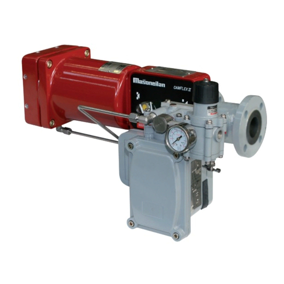
Masoneilan
8013 series
Electropneumatic positioner
Instructions
used with 35002 series Camflex II
and 30000 series Varimax control valves
Masoneilan
Masoneilan
Related Manuals for Dresser Masoneilan 8013 Series
Summary of Contents for Dresser Masoneilan 8013 Series
-
Page 1
Instructions No ES 50004-250 E Rev. B 08/97 Masoneilan 8013 series Electropneumatic positioner Instructions used with 35002 series Camflex II and 30000 series Varimax control valves Masoneilan Masoneilan… -
Page 2: Description And Operation
Preliminary remarks Moreover, before initiating any operation on this positioner the following should be read : 1. Note the serial number for future reference. a) operating instructions pertaining particularly to 2. The positioner is fitted with a powerful magnet : do installation.
-
Page 3: Split-Range Operation
Direct action Changing of action With direct positioner action, an increase in the output a) Reverse the positions of the coil leads on the signal produces a force on the beam moving the flapper terminal board (see Instruction sheet No ES to cover the nozzle.
-
Page 4
Serial connecting The table of Figure 3 summarizes these two operating modes. Positioners model 8013 can be modified on the field to operate two split-ranging valves, selecting the proper To calibrate a positioner for split-ranging operation, cam lobe. proceed as indicated in chapter “Calibration” considering that the connection of the controller on each positioner is Parallel connecting performed as indicated in the table. -
Page 5
Force Balance Spring LOCKNUT (7) Position ADJUSTING SCREW (6) Direct Action BIASING Below Beam SPRING (52) FORCE BALANCE SPRING (8) SPRING LEVER (10) LOCKNUT (11) HOOKING Reverse Action SCREW (12) Below Beam Figure 5 2. Be sure that the coil and the terminal board are Cam mounting and orientation (Figures correct for the input signal characteristics. -
Page 6
The supply connection of the air filter-regulator model 77-4 is 1/4” NPT. Adjust the output pressure of the air Selection of Proper Line on Cam Lobe for filter-regulator to the pressure indicated on the serial Alignment with Cam Follower Bearing plate of the actuator. -
Page 7: Maintenance
Air-to-open valve 12. Adjust signal to proper value corresponding to valve closed position. 5. Shut-off supply pressure. Valve plug should be 13. Adjust the biasing spring (52) so that the valve plug seated. will lift off the seat at the proper closing milliamp 6.
-
Page 8
PARTS REFERENCE Ref. Ref. Ref. Part Name Part Name Part Name Cover Screw Relay Biasing Spring Emblem Mounting Screw (Relay) Mounting Screw (relay) Cover Screw Relay Cap Mounting Screw Serial Plate Diaphragm S/A Magnet S/A Force Balance Spring Lever Bellofram Plate S/A Adjusting Screw Release Spring Gasket… -
Page 9: Troubleshooting
Flexure strip replacement Alignment Rod 1/8”(3,175 mm) Dia. Mounting Screw 1. Remove positioner cover and disconnect coil leads Biasing Spring Adjusting Screw from the terminal board. Disengage the end of the Coil Screw (45) Biasing Spring Bracket (39) force balance spring (8) from the adjusting Biasing Spring (52) screw (6).
-
Page 10
8. Coil stop adjusted to allow approximately (0.8 mm) Electrical circuit (1/32”) flapper travel in front of nozzle. After checking pneumatic circuit, the electrical circuit 9. All mechanism components fastened firmly as should be checked with an ohmmeter as follows: required. -
Page 11
DISTRIBUTOR E.P. & S. — FRANCE 24 bis rue de Picpus 75012 PARIS Tel: +33 (0) 762 682 291 Tel: +33 (0) 650 590 965 ventes@fr-eps.com E.P. & S. — CAMEROON Immeuble Carré d’Or Rue Soppo Priso Côté Chococho, Bonapriso DOUALA Tel: +237 6 52 12 70 95 Tel: +33 (0) 782 006 276…
Preliminary remarks
1. Note the serial number for future reference.
2. The positioner is fitted with a powerful magnet : do
not bring close to it a watch or an instrument likely to
deviate under the influence of a magnetic field.
Introduction
These instructions apply to installation,
adjustments, calibration and eventual repair of
8013 Series Positioners with cam, mounted on
35002 Series Camflex II and 30000 Series Varimax
This version of the Positioner can be manufactured to
meet the requirements of each standard pertaining to :
— protection against explosion for equipment intended
to be installed in an hazardous atmosphere ;
— protection against dust and against water-splash for
tight equipment ;
— sometimes a combination of the two preceding
protections.
The instructions pertaining to these standards as well as
to electric characteristics of the positioner are further
explained in a supplementary Instruction sheet No ES
50004-000 E.
In all instances the operator should therefore be in
possession of the supplementary Instruction
sheet No ES 50004-000 E in addition to this
instruction sheet.
Caution
This equipment should not be installed, kept up or put
into operation without having read and fully understood
before-hand the instructions contained in this
instruction sheet and in the supplementary sheet
No ES 50004-000 E
General
The positioner is an electropneumatic force-balance
device which provides an accurate means of obtaining
at any time a valve stem position corresponding to a
theoretical position envisaged for a DC input signal. In
addition, the positioner provides a convenient means of
split-ranging operation for several valves (usually two)
from a single signal emitted by a single controller. The
positioner may have either direct or reverse action on
either direct or reverse actuators.
The feedback device of this positioner is fitted with one
single cam with several lobes permitting the valve to
present the following characteristics : linear, split-ranging
linear, equal percentage. The cam is directly mounted
on the end of the valve shaft (CAMFLEX II) or on the
pivot of actuator case (Varimax) ; thus avoiding the
drawbacks inherent in the connecting linkage.
Moreover, before initiating any operation on this
positioner the following should be read :
a) operating instructions pertaining particularly to
installation.
b) safety rules listed on the instruction plate attached to
the cover of the device in certain cases (positioners
with explosion-proof housing).
Non-compliance with these rules may bring about faulty
operation of the device, interfere with the installation or
damage it seriously. In addition, such negligence might
expose operating personnel present on the site to grave
hazards.
After Sales Department
Masoneilan has a highly skilled After Sales Department
available for start-up maintenance and repair of our
valves and components parts. Contact the nearest
Masoneilan Sales Office or representative or directly the
After Sales Department of Condé-sur-Noireau Plant.
Any future orders for spare parts should be addressed to
the Spare-Parts Department of our factory at
Condé-sur-Noireau. When such an order is placed you
should always cite in reference the original order and, in
particular, the type and the serial number of the
positioners involved.
Training
MASONEILAN regularly holds training seminars for
technicians in its factory of Condé-sur-Noireau. In order
to attend one of these training seminars you should get
in touch with our local Masoneilan representative or our
Training Department.
BIASING SPRING
PIVOT
COIL
MAGNET
CAM FOLLOWER
CAM
BEARING
Figure 1 – Diagram of Operation
(Example on Camflex II)
2
BEAM
OUTPUT
FORCE BALANCE
SPRING
RELEASE
SPRING
FLAPPER
NOZZLE
RELAY
AIR
SUPPLY
|
Detail Specifications: 1761/1761334-masoneilan_8013_series.pdf file (30 Mar 2023) |
Accompanying Data:
Dresser Masoneilan 8013 Series Valve Positioners PDF Instructions Manual (Updated: Thursday 30th of March 2023 07:56:53 AM)
Rating: 4.9 (rated by 48 users)
Compatible devices: Masoneilan 4700P, Masoneilan SVI II AP-2, HF02-LG, YT-1200 Series, Fisher 3610J, P-2000, MOONEY FLOWGRID SLAM SHUT, Masoneilan SVI II AP.
Recommended Documentation:
Text Version of Instructions Manual
(Ocr-Read Summary of Contents, UPD: 30 March 2023)
-
3, Dresser Masoneilan 8013 Series Direct action With direct positioner action, an increase in the output signal produces a force on the beam moving the flapper to cover the nozzle. The increase in nozzle back pressure increases positioner output pressure to the actuator. The resultant actuator stem motion is transmitted to the force-balance spring, extending the spring until the force exerted on the beam balances the opposing for…
-
1, Masoneilan 8013 series Electropneumatic positioner Instructions used with 35002 series CamflexII and 30000 series Varimax control valves Instructions No ES50004-250E Rev. B 08/97 MasoneilanMasoneilan
… -
10, 8. Coil stop adjusted to allow approximately (0.8mm) (1/32”) flapper travel in front of nozzle. 9. All mechanism components fastened firmly as required. 10. Proper nozzle size selected. Number of nozzle stamped on body of nozzle. The table below indicates nozzle number for each utilization case. Pneumatic circuit In the event of faulty operation of the pos…
-
8, 8 1 2 3 4 5 14 15 16 212018 30 19 23 12 111097 6 8 32 73 33 70 74 ● Recommended Spare Parts ✛ These parts should not be purchased separately since they are staked or press fitted into the case (14). 1 Cover Screw 2 Emblem 3 Cover 4 Mounting Screw 5 Magnet S/A 6 Adjusting Screw 7 Nut 8 Force Balance Spring 9 Screw 10 Spring Lever 11 Nut 12 Hooking Screw (spring) 14 Case ● 15 Term…
-
2, Dresser Masoneilan 8013 Series Preliminary remarks 1. Note the serial number for future reference. 2. The positioner is fitted with a powerful magnet: do not bring close to it a watch or an instrument likely to deviate under the influence of a magnetic field. Introduction This version of the Positioner can be manufactured to meet the requirements of each standard pertaining to: — protection against explosion for equi…
-
6, The supply connection of the air filter-regulator model 77-4 is 1/4” NPT. Adjust the output pressure of the air filter-regulator to the pressure indicated on the serial plate of the actuator. Admissible maximum pressures on the positioner are in accordance with the valve and the actuator on which it is mounted. For CamflexII valves these maximum pressures are indicated in the Instruction No E…
-
7, Air-to-open valve 5. Shut-off supply pressure. Valve plug should be seated. 6. Proceed with the calibration, performing step 9 described below. Air-to-close valve 7. Adjust supply pressure to proper requirement (psig). (See valve catalog for proper supply pressure according to valve size and to pressure drop; see also the serial plate). 8. With a 10mm flat wrench …
-
9, Dresser Masoneilan 8013 Series Flexure strip replacement 1. Remove positioner cover and disconnect coil leads from the terminal board. Disengage the end of the force balance spring (8) from the adjusting screw (6). 2. Remove the two mounting screws (4) and lift the entire operating mechanism from the case. 3. Remove screws (42) and flexure strips (49 and 50) from the beam. Replace coil if necessary per instructions be…
-
5, 2. Be sure that the coil and the terminal board are correct for the input signal characteristics. Refer to table on page 4 of the instruction sheet No ES 50004-000 E for identification code number of these items. Position of the force balance spring The position of the force balance spring (8) in regard to the beam depends on the action of the positioner (see Figure 5). If the posi…
Recommended Instructions:
Latitude 12 5000 Series, FGF376CETK, FinePix J38, ZOB150, MVR041


-
TS SmaS800Inst art Va0/TStruct lve PoS80tion M Ver. PMositio05 SeManM-TS800EN oner eries ual -01/2021 …
TS800 Series 52
-
— ABB MEASUREMENT & ANALYTICS | COMMISSIONING INSTRUCTION TZIDC, TZIDC-110, TZIDC-120 Digital Positioner — ABB Limited Measurement & Analytics Howard Road, St. Neots Cambridgeshire, PE19 8EU UK Tel: +44 (0)870 600 6122 Fax: +44 (0)1480 213 339 Email: [email protected] ABB Automation Products GmbH Measurement & Analytics Schillerstr. 72 32425 Minden Germany Tel: +49 …
TZIDC 60
-
IP80X14-TFJ21GB-BInstallation and Maintenance ManualIP8000/IP8100 0#0 — # — X14 — LElectropneumatic Positioner1 Safety Instructions• This manual contains essential information for the protection of usersand others from possible injury and/or equipment damage.• Read this manual before using the product, to ensure correct handling,and read the manuals of rela …
IP8000 2
-
GE EnergyMasoneilan* Products4700E/4800E Electropneumatic Positioners ATEX Instruction ManualCorrosion resistant positioner • Accurate positioning• Integrated 4000 Series I/P transducer • Optional high-flow capacity …
Masoneilan 4700E 10
Popular Right Now:
Operating Impressions, Questions and Answers:
Table of Contents for Dresser Masoneilan 8013 Series:
-
DISTRIBUTOR * Trademark of the General Electric Company. Other company names and product names used in this document are the registered trademarks or trademarks of their respective owners. © 2014 General Electric Company. All rights reserved. Visit our web-site: www.f r-eps.com E.P. & S. — FRANCE 24 bis rue de Picpus 75012 PARIS Tel: +33 (0) 762 682 291 Tel: +33 (0) 650 590 965 [email protected] E.P. & S. — CAMEROON Im
-
The supply connection of the air filter-regulator model 77-4 is 1/4” NPT. Adjust the output pressure of the air filter-regulator to the pressure indicated on the serial plate of the actuator. Admissible maximum pressures on the positioner are in accordance with the valve and the actuator on which it is mounted. For CamflexII valves these maximum pressures are indicated in the Instruction No EF 50004 E. For Varimax valves, they are indicated in Instruction No EN3000 E Output circuit The pneumatic output connection to the actuator should be particularly tight. Electr
-
Masoneilan 8013 series Electropneumatic positioner Instructions used with 35002 series CamflexII and 30000 series Varimax control valves Instructions No ES50004-250E Rev. B 08/97 MasoneilanMasoneilan
-
8 1 2 3 4 5 14 15 16 212018 30 19 23 12 111097 6 8 32 73 33 70 74 ● Recommended Spare Parts ✛ These parts should not be purchased separately since they are staked or press fitted into the case (14). 1 Cover Screw 2 Emblem 3 Cover 4 Mounting Screw 5 Magnet S/A 6 Adjusting Screw 7 Nut 8 Force Balance Spring 9 Screw 10 Spring Lever 11 Nut 12 Hooking Screw (spring) 14 Case ● 15 Terminal Board S/A 16 Nozzle ✛ 18 Adapter (Flame Arrestor) ● 19 O-Ring ● 20 Relay 21 Mounting Screw (Relay) 23 Screw 30 Serial Plate 32 Force Balance
-
Preliminary remarks 1. Note the serial number for future reference. 2. The positioner is fitted with a powerful magnet: do not bring close to it a watch or an instrument likely to deviate under the influence of a magnetic field. Introduction This version of the Positioner can be manufactured to meet the requirements of each standard pertaining to: — protection against explosion for equipment intended to be installed in an hazardous atmosphere;
-
Flexure strip replacement 1. Remove positioner cover and disconnect coil leads from the terminal board. Disengage the end of the force balance spring (8) from the adjusting screw (6). 2. Remove the two mounting screws (4) and lift the entire operating mechanism from the case. 3. Remove screws (42) and flexure strips (49 and 50) from the beam. Replace coil if necessary per instructions below. 4. Replace damaged flexure strips and reattach beam to the magnet with flexure strips (50) and screws (42). Do not tighten screws.
-
Serial connecting Positioners model 8013 can be modified on the field to operate two split-ranging valves, selecting the proper cam lobe. Parallel connecting Positioners can be used to operate two split-ranging valves ; select the proper cam lobe and utilize a half-force balance spring. The table of Figure 3 summarizes these two operating modes. To calibrate a positioner for split-ranging operation, proceed as indicated in chapter “Calibration” consi
-
8. Coil stop adjusted to allow approximately (0.8mm) (1/32”) flapper travel in front of nozzle. 9. All mechanism components fastened firmly as required. 10. Proper nozzle size selected. Number of nozzle stamped on body of nozzle. The table below indicates nozzle number for each utilization case. Pneumatic circuit In the event of faulty operation of the positioner, where the cause is not readily apparent, check air system as follows: 1. Exert sufficient force on the flapper to cover the nozzle. Valve stem should travel its full strok
-
Direct action With direct positioner action, an increase in the output signal produces a force on the beam moving the flapper to cover the nozzle. The increase in nozzle back pressure increases positioner output pressure to the actuator. The resultant actuator stem motion is transmitted to the force-balance spring, extending the spring until the force exerted on the beam balances the opposing force of the coil. As these two forces equalize, nozzle back pr
Questions, Opinions and Exploitation Impressions:
You can ask a question, express your opinion or share our experience of Dresser Masoneilan 8013 Series device using right now.
 |
[Page 1] Dresser Masoneilan 8013 Series Masoneilan 8013 series Electropneumatic positioner Instructions used with 35002 series CamflexII and 30000 series Varimax control valves Instructions No ES50004-250E Rev. B 08/97 MasoneilanMasoneilan |
 |
[Page 2] Dresser Masoneilan 8013 Series Preliminary remarks 1. Note the serial number for future reference. 2. The positioner is fitted with a powerful magnet: do not bring close to it a watch or an instrument likely to deviate under the influence of a magnetic field. Introduction This v… |
 |
[Page 3] Dresser Masoneilan 8013 Series Direct action With direct positioner action, an increase in the output signal produces a force on the beam moving the flapper to cover the nozzle. The increase in nozzle back pressure increases positioner output pressure to the actuator. The resulta… |
 |
[Page 4] Dresser Masoneilan 8013 Series Serial connecting Positioners model 8013 can be modified on the field to operate two split-ranging valves, selecting the proper cam lobe. Parallel connecting Positioners can be used to operate two split-ranging valves ; select the proper cam lobe a… |
 |
[Page 5] Dresser Masoneilan 8013 Series 2. Be sure that the coil and the terminal board are correct for the input signal characteristics. Refer to table on page 4 of the instruction sheet No ES 50004-000 E for identification code number of these items. Position of the force balance spring… |
 |
[Page 6] Dresser Masoneilan 8013 Series The supply connection of the air filter-regulator model 77-4 is 1/4” NPT. Adjust the output pressure of the air filter-regulator to the pressure indicated on the serial plate of the actuator. Admissible maximum pressures on the positioner are in ac… |
 |
[Page 7] Dresser Masoneilan 8013 Series Air-to-open valve 5. Shut-off supply pressure. Valve plug should be seated. 6. Proceed with the calibration, performing step 9 described below. Air-to-close valve 7. Adjust supply pressure to proper requirement (psig). (See valve catalog for proper … |
 |
[Page 8] Dresser Masoneilan 8013 Series 8 1 2 3 4 5 14 15 16 212018 30 19 23 12 111097 6 8 32 73 33 70 74 ● Recommended Spare Parts ✛ These parts should not be purchased separately since they are staked or press fitted into the case (14). 1 Cover Screw 2 Emblem 3 Cover 4 Mounting Sc… |
 |
[Page 9] Dresser Masoneilan 8013 Series Flexure strip replacement 1. Remove positioner cover and disconnect coil leads from the terminal board. Disengage the end of the force balance spring (8) from the adjusting screw (6). 2. Remove the two mounting screws (4) and lift the entire operatin… |
 |
[Page 10] Dresser Masoneilan 8013 Series 8. Coil stop adjusted to allow approximately (0.8mm) (1/32”) flapper travel in front of nozzle. 9. All mechanism components fastened firmly as required. 10. Proper nozzle size selected. Number of nozzle stamped on body of nozzle. The table below i… |
 |
[Page 11] Dresser Masoneilan 8013 Series DISTRIBUTOR * Trademark of the General Electric Company. Other company names and product names used in this document are the registered trademarks or trademarks of their respective owners. © 2014 General Electric Company. All rights reserved. Visit … |