-
Contents
-
Table of Contents
-
Bookmarks
Quick Links
Instruction Manual
EW2002-AP
Putting You In Control
06/10 Rev D
SVI
II AP
®
Digital Positioner
With Remote Position Sensor
Related Manuals for Dresser Masoneilan SVI II AP
Summary of Contents for Dresser Masoneilan SVI II AP
-
Page 1
Instruction Manual EW2002-AP Putting You In Control 06/10 Rev D II AP ® Digital Positioner With Remote Position Sensor… -
Page 2
Inc. are warranted to be free from defects in materials and workmanship for a period of one year from the date of shipment provided said items are used according to Dresser recommended usages. Dresser, Inc. reserves the right to discontinue manufacture of any product or change product materials, design or specifications without notice. -
Page 3
Safety Information This section provides safety information including safety symbols that are used on the SVI II AP and the safety symbol definition. Important — Please Read Before Installation! Safety Symbols SVI II AP instructions contain WARNINGS, CAUTIONS labels and Notes, where necessary, to alert you to safety related or other important information. -
Page 4
Before using these products with fluids other than air or for non-industrial applications, consult Dresser, Inc. This product is not intended for use in life support systems. Under certain operating conditions, the use of damaged WARNING instruments could cause a degradation of the performance of the system, which can lead to personal injury or death. -
Page 5
SVI II AP Instruction Manual Contents Safety Information ……………………..i Safety Symbols ……………………..i SVI II AP Product Safety……………………ii 1: Introduction ………………………. 1 ValVue Software ……………………… 2 ValVue Lite……………………..2 System Requirements………………….2 ValVue Trial Version ………………….. 2 Operational Overview ……………………3 SVI II AP Features …………………… -
Page 6
Dresser Masoneilan SVI II AP Instruction Manual Wiring the SVI II AP ……………………33 Connecting to the Control Loop ……………….. 33 Verify Wiring and Connections………………..33 3: Check Out and Power Up ………………….35 Overview ……………………….. 35 Position Sensor Principles ………………….35 Check Out Procedures…………………… -
Page 7
Configuration with Pushbutton Display ………………67 Viewing Configuration Data………………..68 VIEW DATA Settings ………………….69 Calibration……………………… 71 Calibrating the SVI II AP Unit Using Pushbuttons…………..71 Correct for Over Travel ………………….72 Adjust Input Signal Range………………… 73 Check-out with a HART Handheld Communicator…………..75 Configuring and Calibrating with ValVue ……………… -
Page 8
Dresser Masoneilan SVI II AP Instruction Manual Physical and Operational Description ………………104 Electronics Module………………….104 Output Switches……………………105 Pneumatic Module ………………….106 Optional Display and Pushbuttons ………………109 SVI II AP Maintenance and Repair ………………. 109 Repair ……………………..109 Tools Needed…………………… -
Page 9
SVI II AP Instruction Manual Figures SVI II AP ……………………..1 SVI II AP Components ………………….8 SVI II AP Dimensions………………….9 Camflex with Mounting Bracket (Side View) ……………. 14 Camflex ATO Mounting (Front View) ………………. 15 Mounting Bracket on Air-to-Close Actuator…………….15 Model 33 Actuator…………………… -
Page 10
Dresser Masoneilan SVI II AP Instruction Manual Split Range with Isolator …………………. 92 Split Range with Supplemental Power Supply — Non-Hazardous ……..94 Intrinsically Safe Installation with Zener Barrier and HART Filter ……..98 Intrinsically Safe Installation with Galvanic Isolator …………100 Block Diagram with I/P Converter and Pressure Sensor ……….. -
Page 11
Tables SVI II AP Installation Steps ………………..10 Magnet Orientation on Rotary Actuators…………….16 Reciprocating Valve Mounting Hole and Turnbuckle Length ……….19 Remote Position Sensor Specifications …………….23 Remote Position Sensor Turnbuckle Length …………… 25 Air Supply Requirements ………………… 29 Double Acting Positioner ATO⁄ATC Settings for Reciprocating Valves …………………. -
Page 12
SVI II AP Instruction Manual This page intentionally left blank. -
Page 13: Introduction
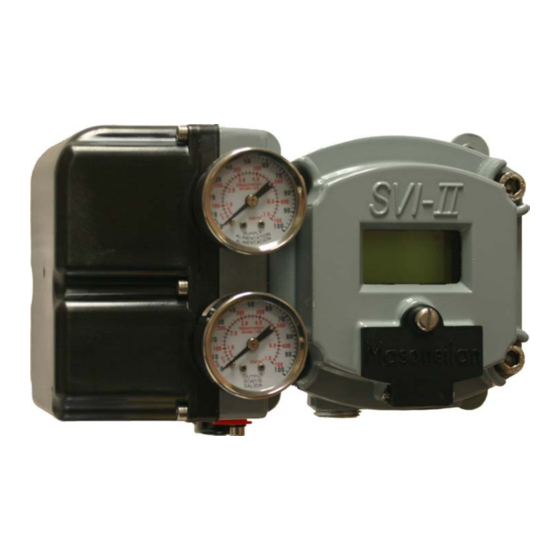
Introduction ® The SVI II AP (Smart Valve Interface) is the next generation of Masoneilan’s intelligent digital valve positioners. The SVI II AP is a high performance, digital valve positioner that combines a local display with remote communication and diagnostic capabilities. The SVI II AP offers a multitude of options that fulfills the broadest range of applications.
-
Page 14: Valvue Software
Dresser Masoneilan SVI II AP Instruction Manual ValVue Software Not only does ValVue provide the ability to quickly and easily set up the SVI II AP you can also monitor operation and diagnose problems with ValVue’s advanced diagnostic capabilities. ValVue Lite ValVue Lite software is shipped with each SVI II AP for positioner calibration and configuration.
-
Page 15: Operational Overview
Introduction Operational Overview Display comparative test results (full version only) Perform diagnostic test procedures (full version only) Advanced and Online Diagnostics The SVI II AP offers various levels of control valve diagnostics. Up to five pressure sensors that detect circuit board temperature, loop current, and reference voltage, are available for diagnostics.
-
Page 16
Dresser Masoneilan SVI II AP Instruction Manual One Model for Rotary or Reciprocating Valves Local Operation⁄calibration⁄configuration with Optional Flameproof Push Buttons and LCD Digital Display Compatible with Air-to-Close or Air-to-Open Actuators Non-contact Magnet Coupled (Hall Effect) Position Sensing for Rotary and… -
Page 17: Available Options
Introduction Available Options Available Options Some of the options available for the SVI II AP are listed below: Remote Position Sensor Two Contact Outputs User Linked to Various Status and Alarm Flags Offshore Construction — Stainless Steel Housing and Components Pushbutton Display About This Manual The SVI II AP Instruction Manual is intended to help a Field Engineer install, setup, and…
-
Page 18
SVI II AP Instruction Manual This page intentionally left blank. -
Page 19: Installation And Set Up
Installation and Set Up Overview The SVI II AP (Smart Valve Interface — see Figure 2 on page
 is the next generation of Masoneilan’s intelligent digital valve positioners. The SVI II AP is a high performance, digital valve positioner that combines a local display with remote communication and diagnostic capabilities.
 -
Page 20: Svi Ii Ap Components
Dresser Masoneilan SVI II AP Instruction Manual SVI II AP Cover SVI II AP Assembled Pneumatic Train and Cover (I/P Module, Relay) Electronics Manifold Module Relay Figure 2 SVI II AP Components…
-
Page 21: Svi Ii Ap Dimensions And Weights
Installation and Set SVI II AP Dimensions and Weights SVI II AP Dimensions and Weights Figure 3 illustrates the dimensions and weight of the SVI II AP. Figure 3 SVI II AP Dimensions…
-
Page 22: Pre-Installation Issues
Dresser Masoneilan SVI II AP Instruction Manual Pre-Installation Issues Storage If the SVI II AP is stored for a long duration, you must keep the housing sealed against weather, fluids, particles, and insects. To prevent damage to the SVI II AP: Use the plugs provided with shipment to plug the ¼…
-
Page 23: Installation Notes
Installation and Set Installation Notes Table 1 SVI II AP Installation Steps (Continued) Step No. Procedure Reference Connect the positioner to the HART Control Loop See page 33 for instructions. segment by installing the SVI II AP wiring. Configure/Calibrate using LCD Pushbutton display See page 67 for instructions Configure/Calibrate using a Hart Hand Held See page 75 for instructions…
-
Page 24: Before Powering Up
Dresser Masoneilan SVI II AP Instruction Manual Before Powering Up Before powering up the SVI II AP: 1. Verify that the pneumatic connections and electronic cover screws are tightened. This is important to maintain the ingress protection level and the integrity of the flameproof enclosure.
-
Page 25: Filter Regulator And Tubing
Installation and Set Filter Regulator and Tubing Filter Regulator and Tubing The use of a Masoneilan filter regulator with a 5-micron filter is recommended for the air supply. Use 1⁄4″ (6.35 mm) minimum tubing between filter regulator, SVI II AP and the actuator, with 3⁄8″…
-
Page 26: Camflex With Mounting Bracket (Side View)
Dresser Masoneilan SVI II AP Instruction Manual 4. On vacuum service, the valve shaft can be drawn into the body by the vacuum acting on the shaft, but the magnetic coupling must be assembled flush with the mounting bracket with the shaft pulled fully out to its thrust bearing. Check that the endplay from the vacuum position to the fully extended position is less than 0.06 in.
-
Page 27: Camflex Ato Mounting (Front View)
Installation and Set Required Tools Figure 5 Camflex ATO Mounting (Front View) Figure 6 Mounting Bracket on Air-to-Close Actuator…
-
Page 28: Model 33 Actuator
Dresser Masoneilan SVI II AP Instruction Manual Table 2 Magnet Orientation on Rotary Actuators Rotary Actuator Type Magnet Setting — ATO Magnet Setting — ATC Camflex Actuator is energized Magnet Axis is Vertical Figure 6 Camflex Actuator is de-energized Magnet Axis is Vertical Figure 5 ®…
-
Page 29: Magnet Orientation On Rotary Valve Shafts
Installation and Set Magnet Orientation on Rotary Magnet Orientation on Rotary Valve Shafts The same mounting hardware is used for Models 35, 30 actuators. For each actuator type the magnetic coupling must be properly oriented to the active sensing angle of the positioners Hall Effect sensor.
-
Page 30: Magnet Holder For Reciprocating Valves
Dresser Masoneilan SVI II AP Instruction Manual 3. Select mounting hole A, B, C or D for the stroke of the valve. For example, hole B is shown in Figure 10 on page 19 for a size 10 actuator with 1.0″ stroke. Unless otherwise specified, the SVI II AP mounting assumes that the actuator is in the normal upright position.
-
Page 31: Reciprocating Valve Mounting Bracket
Installation and Set Mounting the SVI II AP on a Figure 9 Reciprocating Valve Mounting Bracket Figure 10 Lever for Model 87/88 Multispring Actuator Table 3 Reciprocating Valve Mounting Hole and Turnbuckle Length Actuator Size Stroke Mounting Hole Lever Hole Turnbuckle Length Masoneilan 6 and 10…
-
Page 32: Dismantling The Svi Ii Ap From Reciprocating Valves
Dresser Masoneilan SVI II AP Instruction Manual Table 3 Reciprocating Valve Mounting Hole and Turnbuckle Length (Continued) Actuator Size Stroke Mounting Hole Lever Hole Turnbuckle Length Masoneilan 0.5 — 0.8″ 5.25″ (12.7 — 20.32 mm) (133.35 mm) >0.8 – 1.5″…
-
Page 33: Installing The Svi Ii Ap For Double- Acting Operation
Installation and Set Installing the SVI II AP for Double- Installing the SVI II AP for Double- Acting Operation This section explains how to mount the SVI II AP for the 84/85/86 kit for double-acting valve positioner configurations. To mount the kit: 1.
-
Page 34: Bracket Configuration Strokes .5 — 2.50″ And 3-6
Dresser Masoneilan SVI II AP Instruction Manual 4. Mount take-off bracket to stem block at angle which keeps turnbuckle assembly parallel to stem (Figure 14) using: a. For top: two plain 5/16 flat washers, helical spring washer 5/16, two hex nuts 5/ 16-18 regular.
-
Page 35: Installing The Svi Ii Ap Remote Position Sensor
Installation and Set Installing the SVI II AP Remote Installing the SVI II AP Remote Position Sensor An option that is available for the SVI II AP is the Remote Position Sensor. The Remote Position Sensor is a remotely mounted position-sensing device, that is connected electrically to an SVI II AP valve positioner.
-
Page 36: Remote Position Sensor Mounting Instructions
Dresser Masoneilan SVI II AP Instruction Manual Remote Position Sensor Mounting Instructions Tools Needed: 7/16″ open end wrench 6 mm hex wrench 2.5 mm hex wrench Blade screwdriver The instructions below cover mounting the Remote Mount NOTE Sensor to both reciprocating and rotary actuators. The two mounting kits share only one part;…
-
Page 37: Remote Position Sensor Mounting
Installation and Set Remote Position Sensor Mounting Lever Lever Bracket Turnbuckle Bracket Remote Position Sensor Mounted Remote Position Sensor Mounted on Reciprocating Actuator on Rotary Actuator Figure 17 Remote Position Sensor Mounting Table 5 Remote Position Sensor Turnbuckle Length Actuator Size Stroke Turnbuckle Length 6 and 10…
-
Page 38: Remote Position Sensor (Cover Removed) And Wiring
Dresser Masoneilan SVI II AP Instruction Manual 9. At the other end of the cable, insert the ferrules into the terminal labeled REMOTE; black-to-black, brown-to-brown and red-to-red. When performing this step, be careful not to side-load the terminal levers. Remote Position Sensor…
-
Page 39: Configuring The Svi Ii Ap For Remote Position Sensing
Installation and Set Configuring the SVI II AP for Configuring the SVI II AP for Remote Position Sensing After the Remote Position Sensor is installed and cabled to the SVI II AP, the SVI II AP needs to be configured so that valve position is sensed by Remote Position Sensor. A digital communication software tool is provided on the CD shipped with the SVI II AP for this purpose.
-
Page 40: Smarts Assistant — Commissioning The Remote Position Sensor
Dresser Masoneilan SVI II AP Instruction Manual Configuring the SVI II AP Using SMARTS Assistant To configure the SVI II AP: 1. Start SMARTS Assistant Standard by clicking the desktop icon or by selecting the program through the Start menu.
-
Page 41: Connecting The Tubing And Air Supply
Installation and Set Connecting the Tubing and Air Connecting the Tubing and Air Supply The last step in hardware installation for the SVI II AP is to connect the air supply to the positioner. This section describes the process for connecting the tubing and air supply to a single and double acting positioner.
-
Page 42: Single Acting Positioner
Dresser Masoneilan SVI II AP Instruction Manual Never exceed the lower of actuator maximum rated supply WARNING pressure 100 psi (6.9 bar, 689.7 kPa) for single acting or 150 psi (10.4 bar, 1035 kPa) for double acting positioner. Damage to equipment or injury to personnel can result.
-
Page 43: Double Acting Positioner
Installation and Set Double Acting Positioner Double Acting Positioner The Double Acting (DA) relay has a pair of opposed pneumatic outputs. When Output 1 delivers air to one side of the actuator, Output 2 vents air from the opposite side of the actuator piston.
-
Page 44: Connecting The Air Supply
Dresser Masoneilan SVI II AP Instruction Manual Balance Pressure The double-acting relay is designed to deliver pressure on both sides of a piston type actuator, so that the cylinder can provide the required thrust and stiffness. This stiffness is factory adjusted to 70% of the supply pressure. This means that, without any unbalance forces from the valve stem, both outputs deliver roughly 70% of air supply pressure.
-
Page 45: Wiring The Svi Ii Ap
Installation and Set Wiring the SVI II AP Wiring the SVI II AP The procedure below outlines wiring the SVI II AP. Comply with current national and local regulations for WARNING electrical installation work. Comply with national and local explosive atmosphere regulations.
-
Page 46
Dresser Masoneilan SVI II AP Instruction Manual 5. If voltage is less than 9 V and polarity is correct, voltage compliance of current source is inadequate. 6. Connect a milliammeter in series with the current signal. Verify that the source can supply 20 mA to SVI II AP input. -
Page 47: Check Out And Power Up
Check Out and Power Up Overview This section provides the checkout procedures required to determine if the SVI II AP is in working order and to power up the unit. Perform all procedures in this section before putting the SVI II AP into operation.
-
Page 48: Check Out Procedures
Dresser Masoneilan SVI II AP Instruction Manual Check Out Procedures SVI II AP checkout consists of physical and operational checkout procedures. The physical checkout procedures are listed below: Inspect the Actuator, Linkages, or Rotary Adapter Verify the Mounting and Linkage Adjustment…
-
Page 49: Verify Mounting And Linkage Adjustment
Check Out and Power Up Verify Mounting and Linkage Verify Mounting and Linkage Adjustment Inspect the mounting and make any needed adjustments before running the positioner and checking the digital configuration. Checking the Magnet There are two methods of checking the SVI II AP magnet: Perform a visual inspection Use ValVue to check the magnet Performing a Visual Inspection…
-
Page 50: Magnet Orientation For 90° Valve Rotation With De-Energized Actuator
Dresser Masoneilan SVI II AP Instruction Manual Increasing Signal = CCW Rotation ° Magnet Axis with Valve Closed Figure 24 Magnet Orientation for 90° Valve Rotation with De-energized Actuator Disk Washer Figure 25 Magnet Holder for Reciprocating Valves…
-
Page 51: Checking The Air Supply
Check Out and Power Up Checking the Air Supply Figure 26 Reciprocating Valve Mounting Bracket Using ValVue to Check Magnet Position Use this procedure to check the magnet using ValVue: 1. Connect to the positioner in accordance with the ValVue instructions. For further information refer to the ValVue Instruction Manual.
-
Page 52: Checking The Electronic Module Connections
Dresser Masoneilan SVI II AP Instruction Manual ® Do not use Teflon pipe seal tape as it can shred into particles CAUTION harmful to the pneumatic components. Checking the Electronic Module Connections Do not remove the instrument cover or connect to an…
-
Page 53: Connections To Electronics Module (Via Terminal Board)
Check Out and Power Up Checking the Electronic Module Configuration Lock Position Retransmit Jumper SW #2 SW #1 Process Variable I/P Connector Remote Position Sensor Input 4- 20 mA Input Signal Display Figure 27 Connections to Electronics Module (via Terminal Board) When an SVI II AP is turned on it is advisable to apply the air NOTE supply before applying the electrical input signal.
-
Page 54: Operational Checkout
Dresser Masoneilan SVI II AP Instruction Manual Operational Checkout The operational checkout of the SVI II AP consists of: 1. Connecting the SVI II AP to a current source. 2. Powering up the SVI II AP. 3. Checking the pushbutton locks.
-
Page 55: Pushbutton Locks And Configuration-Lock Jumper
Check Out and Power Up Pushbutton Locks and 3. Reinstall the cover and display. 4. Adjust current to 12 mA. On initial power up of a newly installed SVI II AP, the positioner starts up in NORMAL mode and is operational in the default factory configuration.
-
Page 56
Dresser Masoneilan SVI II AP Instruction Manual Hardware Configuration Lock Additional security is achieved using the hardware configuration-lock jumper shown in Figure 27 on page 41. When set to the secure position, by shorting the two-pin header, configuration and calibration are not possible using the local interface or any HART communication tool. -
Page 57: Using The Digital Interfaces
Using the Digital Interfaces Overview This section describes three ways to communicate, configure, and calibrate the SVI II AP. The Smart Valve Interface is truly a smart device capable of: Streamlining the valve positioning function Providing diagnostic information Improving precision of process control Communicating critical information locally and remotely The four available communication tools listed below offer increasing levels of functionality.
-
Page 58: Valvue
Dresser Masoneilan SVI II AP Instruction Manual ValVue ValVue combines the power of the PC with the features of the SVI II AP for ease of use and automation of positioner operation and full access to all data. ValVue Lite is provided with all SVI II AP positioners and is recommended for set up, service and maintenance where a PC or laptop is permitted.
-
Page 59: Pushbuttons
Using the Digital Pushbuttons Pushbuttons The local pushbuttons are located behind a hinged cover, directly below the display window. To open the cover loosen the screw and swing the cover down. Always re-fasten the cover after use to protect the pushbuttons from environmental contamination.
-
Page 60
Dresser Masoneilan SVI II AP Instruction Manual To determine how to display and select a specific parameter value or configuration option, refer to the menu structure diagrams shown in Figure 29 on page 49 through Figure 32 on page 56. When using these diagrams as a map you can move through the menus to the function you needed. -
Page 61: Display Menus
Using the Digital Display Menus Display Menus NORMAL Operating Mode and MANUAL Mode Menus When you leave the NORMAL mode to go to MANUAL mode the valve is placed in the last position it was in when leaving NORMAL. When in the MANUAL mode the device does not respond to the 4 — 20 mA signal.
-
Page 62: Configure Menu
Dresser Masoneilan SVI II AP Instruction Manual Configure Menu Because calibration depends on certain configuration options you must perform Configuration before you perform Calibration when installing the SVI II AP for the first time. If a change is made in the Air-to-Open / Air-to-Close configuration option or if you move the SVI II AP to a different valve or make any change to the valve position linkage, you must run the find STOPS calibration again.
-
Page 63
Using the Digital Configure Menu ATO / ATC This procedure can cause the valve to move. Before WARNING proceeding be sure the valve is isolated from the process. Keep hands clear from moving parts. The positioner must be configured as Air-to-Open, ATO, or as Air-to-Close, ATC. This parameter is toggled by the * button. -
Page 64: Guidelines For Characteristic Choice
Dresser Masoneilan SVI II AP Instruction Manual Tight Shutoff Tight Shutoff is an optional performance feature that prevents leakage at the closed position. Without this feature, at the closed position with an input signal of 0%, the valve may be forced tight against the seat with maximum available actuator force or it may be only touching the seat with minimum force.
-
Page 65
Using the Digital Configure Menu Table 10 Guidelines for Characteristic Choice (Continued) Valve Type and Built In Characteristic Desired Installed Standard Positioner Valve Position Characteristic Selection Characteristic Varimax Linear LINEAR Varimax Equal Percentage EQUAL50 21000 series Model # 21X1X or 41000 series Linear LINEAR Model # 41X1X with LINEAR TRIM… -
Page 66: Calibration Menu
Dresser Masoneilan SVI II AP Instruction Manual Calibration Menu The Calibration Menu shown in Figure 31 provides access to all the calibration functions for the SVI II AP. If a change is made in the Air-To-Open/Air-To-Close configuration option or if you move the SVI II AP to a different valve or make any change to the valve position linkage, you must run the find STOPS calibration again.
-
Page 67: View Data Menu
Using the Digital VIEW DATA Menu VIEW DATA Menu This menu can be entered either from the MANUAL Mode Menu or from the NORMAL Mode Menu. The VIEW DATA menu allows you to read the current configuration, calibration, and status information. This information cannot be changed from the VIEW DATA menu. Exiting from the VIEW DATA menu returns the previous menu.
-
Page 68: View Data Menu
Dresser Masoneilan SVI II AP Instruction Manual VIEW DATA VIEW ERR ACTUATOR TYPE SINGLE OR DOUBLE ACTION TYPE ATO or ATC VALVE CHARACTERISTICS LINEAR, EQ% 30:1, EQ% 50:1, EQ% CAMFX, QUICK 50, CUSTOM PRESSURE UNITS PSI, BAR, KPA TIGHT SHUTOFF T.S.
-
Page 69: Failsafe Mode
Using the Digital FAILSAFE Mode FAILSAFE Mode FAILSAFE mode cannot be selected from any of the previous menus. FAILSAFE mode and display are initiated by detection of a critical fault in the positioner or the valve system. There are two ways to deal with a FAILSAFE condition: correct the problem and clear the error messages or run through the FAILSAFE menu, view error messages, enter MANUAL mode and RESET.
-
Page 70: View Err Diagnostics Messages
Dresser Masoneilan SVI II AP Instruction Manual FAILSAFE Menu MANUAL MODE CYCLING MENU FAILSAFE VIEW ERR RESET CLR ERR MANUAL Instant Pressing * Action WAIT Quickly Flashes displays the first error, pressing a second time displays the second error. Keep pressing to see all errors until VIEW ERR appears.
-
Page 71: Error Messages
Using the Digital VIEW ERR Diagnostics Messages Table 11 Error Messages Description Action Cause RESET Reset occurred due to command or power up. Always Warning Normal operation present after power up. on power up always sets RESET. RESET is sent by HART communications.
-
Page 72
Dresser Masoneilan SVI II AP Instruction Manual Table 11 Error Messages (Continued) Description Action Cause EXT DIAG An extended diagnostic procedure failed to complete Warning Pneumatic / mechanical, configuration CMD STOP HART command aborted Warning Bad data range or data limitation… -
Page 73: Display And Clear Error Messages
Using the Digital Display and Clear Error Messages Table 11 Error Messages (Continued) Description Action Cause PRES3 ER Temperature compensated pressure sensor 3 Warning reading is outside the range or supply pressure recorded is >120 psi (8.28 bar, 828 kPa) PRES4 ER Temperature compensated pressure sensor 4 Warning…
-
Page 74: Return To Normal Operation
Dresser Masoneilan SVI II AP Instruction Manual Return to Normal Operation Always return the positioner to NORMAL operating mode to resume control by the input signal. Use this procedure to return to NORMAL mode from any menu. 1. Press + or — repeatedly until MANUAL or NORMAL appears.
-
Page 75: Valvue
Please refer to the ValVue Instruction manual included on the ValVue CD ROM. Installation of ValVue Software, and Registration For assistance contact the nearest Masoneilan Dresser Sales Office, your local Masoneilan representative or email svisupport@masoneilan.com. Visit our web page at http:/www.masoneilan.com. ValVue Lite and a 60-day trial version of ValVue are included with the SVI II AP.
-
Page 76: System Requirements
Dresser Masoneilan SVI II AP Instruction Manual System Requirements ® ValVue Lite runs on IBM compatible computers. Minimum requirements for all versions of ValVue software are: ® Windows 2000, XP, and Windows Server 2003 64 MB RAM Hard drive available space 35 MB…
-
Page 77: Configuration And Calibration
Configuration and Calibration Configuration and Calibration This section provides procedures to: View configuration data and status messages for the SVI II AP Configure the SVI II AP Calibrate and tune the SVI II AP Observe all warnings as the valve moves during these procedures. These procedures can cause the valve to move.
-
Page 78: Pushbuttons And Local Display For Configuration And Calibration
Dresser Masoneilan SVI II AP Instruction Manual System Requirements ValVue Lite runs on IBM compatible computers. Minimum requirements for all versions of ValVue software are Windows 2000, and XP, 64 MB RAM, a serial port connected to a HART modem, and a CD-ROM drive.
-
Page 79: Pushbutton Locks And Configuration-Lock Jumper
Configuration and Calibration Pushbutton Locks and Pushbutton Locks and Configuration-Lock Jumper Before performing any of these functions with the local display you must first ensure that the pushbuttons are placed in the unlocked mode using ValVue Lite. The positioner ships in the unlocked mode.
-
Page 80: Viewing Configuration Data
Dresser Masoneilan SVI II AP Instruction Manual Viewing Configuration Data To view SVI II AP configuration data: 1. Access the VIEW DATA menu from the MANUAL menu by pressing the + button. 2. In the VIEW DATA menu, press * to examine the configuration.
-
Page 81: View Data Settings
Configuration and Calibration VIEW DATA Settings VIEW DATA Settings Table 13 VIEW DATA Settings Typical Setting Optional Setting SINGLE DOUBLE LINEAR EQ% 30:1 EQ% 50:1 EQ% CAMFX QUICK 50 CUSTOM 0.00 2.00 TS OFF TS ON 4.00 4.00 SIG LO SIG LO 20.00 12.00…
-
Page 82: Configuration Pushbutton Guide
Dresser Masoneilan SVI II AP Instruction Manual CONFIG CONFIGuration Menu CONFIG Air to Charact Language Pressure Tight Shut-off Setup Menu Menu Menu Units Menu Menu Turn tight shutoff on or off to provide maximum actuator Press * to select option.
-
Page 83: Calibration
Configuration and Calibration Calibration Calibration Always perform configuration before running calibration NOTE functions. Pilot Trim Valve Applications require the use of the Manual CAUTION Stop calibration procedure. Do not run Find Stops or the ValVue Setup Wizard on valves with Pilot Trim or damage to the valve will occur.
-
Page 84: Correct For Over Travel
Dresser Masoneilan SVI II AP Instruction Manual Calibration using Auto Tune To auto tune the SVI II AP: 1. Press * to begin the Autotune procedure. This takes 3 to 10 minutes and strokes the valve in large and small steps to set the PID parameters for best positioning response.
-
Page 85: Adjust Input Signal Range
Configuration and Calibration Adjust Input Signal Range Adjust Input Signal Range SIG LO displays the input signal that corresponds to the full closed (ATO) or full open (ATC) position of the valve. 1. If the displayed value is: Correct, press + to advance to the next item. Not correct, press * to display value of SIG LO.
-
Page 86: Calibration Pushbutton Guide
Dresser Masoneilan SVI II AP Instruction Manual CALIBration Menu CAUTION: These functions stroke the valve over its full range. Do not perform while the valve is controlling the process. CALIB <VALUE> <VALUE> <VALUE> STOPS TUNE SETUP STOP OP SIG LOW SIG HIGH <VALUE>…
-
Page 87: Check-Out With A Hart Handheld Communicator
Configuration and Calibration Check-out with a HART Handheld Check-out with a HART Handheld Communicator This section covers a subset of the functions available with HART. For a complete description refer to Chapter 4 Using the Digital Interfaces. If the SVI II AP is not equipped with optional pushbuttons and local display the checkout and configuration is performed using the standard HART communications interface.
-
Page 88
Dresser Masoneilan SVI II AP Instruction Manual NOTE “ Process applied to the non-primary variable is outside the operating limits of the field device” Proceed with the following steps: 1. Press NEXT. 2. Field device has more status available. 3. Press NEXT. -
Page 89: Configuring And Calibrating With Valvue
Configuration and Calibration Configuring and Calibrating with Configuring and Calibrating with ValVue ValVue Lite is the most complete and easiest to use configuration tool. ValVue Lite is provided with each SVI II AP. ValVue or ValVue Lite provides a personal computer interface for configuring and calibrating SVI II AP.
-
Page 90
SVI II AP Instruction Manual This page intentionally left blank. -
Page 91: Overview
Wiring an SVI II AP Overview The SVI II AP is used as a current loop device drawing power and analog input signal from a precision current source. This section describes wiring configurations using HART digital communications operating in the 4 — 20 mA current mode. System Connections All system connections must comply with the HART Communications Protocol Specifications.
-
Page 92: Wiring Guidelines
Dresser Masoneilan SVI II AP Instruction Manual Do not connect a HART modem and PC to a control circuit CAUTION unless the controller is HART compatible or has a HART filter. Loss of control or a process upset may occur if the controller output circuit is not compatible with HART signals.
-
Page 93: Svi Ii Ap Setups
Wiring an SVI II AP SVI II AP Setups Cabling must be shielded to prevent electrical noise that would interfere with the HART tones, with the shield grounded at only one location. Signal must be properly grounded in only one place. For details and calculation methods for wiring resistance, and NOTE capacitance and for calculation of cable characteristics please…
-
Page 94: General Purpose And Explosion Proof Installation
Dresser Masoneilan SVI II AP Instruction Manual Hazardous Area Non-Hazardous Area Power SVI II AP Supply 220 Ohms HART compliant control system output card HART Modem ValVue HHC375 Figure 38 General Purpose and Explosion Proof Installation…
-
Page 95: Intrinsically Safe Installation
Wiring an SVI II AP SVI II AP Setups Single Channel Zener Barrier Power Supply SVI II AP Barrier Resistance 220 Ohms HART Compliant Control System Output Card HART Modem ValVue HHC375 Figure 39 Intrinsically Safe Installation…
-
Page 96: Grounding Practices
Dresser Masoneilan SVI II AP Instruction Manual Grounding Practices To ensure proper grounding make sure that case, signal, and ground connections are made in compliance with the plants normal grounding practices. Any point in the loop can be referenced to ground, but there must never be more than one ground point. Normally ground is connected at the controller or at the intrinsic safety barrier.
-
Page 97: Wire Size And Conduit
Wiring an SVI II AP Wire Size and Conduit Table 15 Compliance Voltage for Galvanic Isolator with 22 AWG Cable Voltage at SVI II AP at 20 mA 9.0 V Drop in 22 AWG cable, 3000 ft. long (30 ohms per 1000 feet) 1.8 V Required voltage at Isolator 10.8 V…
-
Page 98: Hart Physical Layer Compliance Of The Control System
Dresser Masoneilan SVI II AP Instruction Manual HART Physical Layer Compliance of the Control System Communications to a SVI II AP requires a HART-compliant communications loop. The HART protocol specifies the noise level, impedance requirements, and configuration of the loop. The controller or output card of the control system must comply with the Physical Layer Specification.
-
Page 99: Cabling And Interconnection Requirements
Wiring an SVI II AP Cabling and Interconnection Cabling and Interconnection Requirements Interconnections are made using shielded twisted pair cables. The shield is connected to ground at one point only. The signal loop is grounded at only one point in accordance with plant electrical standards.
-
Page 100: Split Range Applications
Dresser Masoneilan SVI II AP Instruction Manual Split Range Applications The SVI II AP is designed to operate in split range configurations supporting up to three control valves connected to a single controller output. Minimum input current span for each SVI II AP is 5 mA. For each positioner the upper range value is between 8 and 20 mA and the lower range value is between 4 and 14 mA.
-
Page 101: Setting Loop Addresses For Split Range Systems
Wiring an SVI II AP Setting Loop Addresses for Split Setting Loop Addresses for Split Range Systems When more than one positioner is installed in a single current loop, the HART loop address of each device must be set to 1, 2, or 3 (or other non-zero values) to allow a HART master to recognize each SVI II AP when connected to all three devices on a single current loop.
-
Page 102: Multiple Output Circuit Control System
Dresser Masoneilan SVI II AP Instruction Manual Multiple Output Circuit Control System ValVue supports HART devices including, the SVI II AP with non-zero polling addresses and supports for multiple SVI II AP on the same loop, for split ranging. To enable this support, check the Multidrop box as shown in Figure 41.
-
Page 103: Isolators
Wiring an SVI II AP Isolators Isolators Another solution is to use an Intrinsic Safety Isolator for each loop as shown in Figure 42 on page 92. A number of manufacturers make suitable isolators designed for use with HART output circuits. Using an IS Isolator allows up to three SVI II AP to be operated from a single 4 — 20 mA DCS output.
-
Page 104: Split Range With Isolator
Dresser Masoneilan SVI II AP Instruction Manual Hazardous Area Non-Hazardous Area Power Supply Power Supply I.S. Galvanic HART Address = 1 Isolator HART Filter Control System Output Card HART Modem ValVue HART Address = 2 I.S. Galvanic Isolator Figure 42 Split Range with Isolator…
-
Page 105: Supplemental Power Supply
Wiring an SVI II AP Supplemental Power Supply Supplemental Power Supply Another approach is to boost the compliance voltage of the DCS using a supplemental power supply (see Figure 43 on page 94) with the split ranged SVI II AP positioners connected in series with the supply.
-
Page 106: Required Practices For Explosion Proof Installations
Dresser Masoneilan SVI II AP Instruction Manual Non-Hazardous Area Power Supply HART Address = 1 Supplemental (voltage) HART Power Supply Filter Control System Output Card HART Modem ValVue HART Address = 2 Figure 43 Split Range with Supplemental Power Supply — Non-Hazardous Required Practices for Explosion Proof Installations The SVI II AP is provided with two threaded conduit entries.
-
Page 107: Clarification Of Terminology
Wiring an SVI II AP Clarification of Terminology Clarification of Terminology In Factory Mutual Research and Canadian Standards Association codes, Explosion Proof means use of approved enclosures and conduit enclosed cables, but in ATEX countries, this method is called Flameproof. In ATEX countries, Explosion Proof means both Flameproof and Intrinsically Safe.
-
Page 108
SVI II AP Instruction Manual This page intentionally left blank. -
Page 109: Hart Communications With Intrinsic Safety
HART Communications with Intrinsic Safety Overview When an SVI II AP is installed in a hazardous area in accordance with the applicable codes and standards for Intrinsic Safety there are wiring considerations for successful operation in addition to the requirements for safety. The choice and application of intrinsic safety barriers requires special training.
-
Page 110: Hart Barrier Compliance
Dresser Masoneilan SVI II AP Instruction Manual HART Barrier Compliance The intrinsic safety barrier must be designed to transmit the HART signals in both directions. Both passive zener diode barriers and active galvanic isolators are offered with HART compliance. Consult the manufacturer or refer to the documents listed at the end of this instruction manual.
-
Page 111: Output Channel Isolation
HART Output Channel Isolation Output Channel Isolation The designer of the signaling circuit where the SVI II AP is to be installed must consider the 8 design rules in Wiring Guidelines (see “Wiring Guidelines” on page 80 of this manual). In particular, the control system output interface has analog output channels that are galvanically isolated and share a common ground or are separated from ground by the current control transistor or sense resistor.
-
Page 112: Intrinsically Safe Installation With Galvanic Isolator
Dresser Masoneilan SVI II AP Instruction Manual Hazardous Area Non-hazardous Area SVI II AP Power Power Supply Supply I.S. Galvanic Isolator HART Hart Compliant Filter Control System Output Card HART Modem ValVue HHC375 Figure 45 Intrinsically Safe Installation with Galvanic Isolator…
-
Page 113: Modem And Computer Use In Intrinsically Safe Circuits
HART Modem and Computer Use in Modem and Computer Use in Intrinsically Safe Circuits Many HART modems that are in use today are not approved for connections to Intrinsically Safe control circuits. Most portable computers are NOT approved for use in hazardous areas.
-
Page 114
SVI II AP Instruction Manual This page intentionally left blank. -
Page 115: Operation And Maintenance
Operation and Maintenance Principle of Operation The SVI II AP Electro Pneumatic Valve Positioner receives an electrical position setpoint signal from a controller or other device and compares the position setpoint input signal to the valve position. The difference between the position setpoint and position feedback is interpreted by the position control algorithm.
-
Page 116: Physical And Operational Description
Dresser Masoneilan SVI II AP Instruction Manual Physical and Operational Description The SVI II AP is housed in an industrial, tough, weatherproof, corrosion resistant aluminum housing that has been designed for operation in hazardous areas as listed in Appendix B. Electrical connections are made through two 1/2″ NPT conduit entries.
-
Page 117: Output Switches
Operation and Maintenance Output Switches Temperature Sensor A temperature sensor is located in the electronics module and measures ambient temperature. This measurement is used to provide temperature compensation for the position and pressure sensors and other internal electronic components. The temperature is read via the HART communication link to provide a warning of excessive ambient temperature at the positioner.
-
Page 118: Pneumatic Module
Dresser Masoneilan SVI II AP Instruction Manual Switch Settings The two digital output switches can be opened or closed in response to conditions that the SVI II AP detects. These conditions are: Always Normal Position — the switch is not controlled by the SVI II AP and remains in it’s default position…
-
Page 119: Pneumatic Module With Single Acting Relay
Operation and Maintenance Pneumatic Module Single Acting Pneumatic Relay The single acting pneumatic relay amplifies the pressure from the I/P and increases airflow as required for stable, responsive, actuator performance. The single acting relay operates on any supply pressure that is at least 5 psi (.345 bar, 34.5 kPa) above the required actuator pressure, up to 100 psi (6.9 bar, 690 kPa).
-
Page 120: Double Acting Pneumatic Relay
Dresser Masoneilan SVI II AP Instruction Manual Double Acting Pneumatic Relay The double acting pneumatic relay amplifies the pressure from the I/P and provides a pair of high flow output signals for operating a double acting cylinder actuator. The double acting relay operates on any supply pressure that is at least 5 psi (.345 bar, 34.5 kPa)
-
Page 121: Optional Display And Pushbuttons
Operation and Maintenance Optional Display and Pushbuttons Double Acting Supply Pressure Balance After installation on the actuator, set supply pressure in accordance with actuator specifications. Do not exceed the maximum pressure rating of the actuator. The double acting relay is adjusted at the factory and set to 70% of supply pressure. If adjustment is required consult the factory.
-
Page 122: Tools Needed
Dresser Masoneilan SVI II AP Instruction Manual Tools Needed 5 mm hex key 3 mm hex key Display Cover Removal and Installation The display cover (shown in Figure 49) is provided as an option for the SVI II AP. If you have an SVI II AP with a solid cover and would like to replace the solid cover with a display cover follow the instructions below for removal and installation.
-
Page 123
Operation and Maintenance Display Cover Removal and Installing the SVI II AP Display Cover After replacing the SVI II AP Display Cover you must power NOTE up the unit (see “Powering Up the SVI II AP” on page 42 of this guide). -
Page 124: I⁄P Module Removal And Installation
Dresser Masoneilan SVI II AP Instruction Manual I⁄P Module Removal and Installation Prior to removing the pneumatic components it is necessary to remove the electronics module cover (see “Removing the SVI II AP Display Cover” on page 110) and the pneumatic cover first.
-
Page 125: Relay Removal And Installation
Operation and Maintenance Relay Removal and Installation Pneumatic Cover Installation To install the pneumatic cover: 1. Place the cover over the pneumatic module. 2. Using a 3 mm hex key, install the six screws around the perimeter of the cover and torque to 8 in-lb (.9 N-m).
-
Page 126: Repair By Replacement
Dresser Masoneilan SVI II AP Instruction Manual Repair by Replacement Using ValVue and repair-by-replacement is the fastest method to service an SVI II AP. See the ValVue instruction manual for details regarding uploading and downloading configuration files. Upload all configuration information from the installed positioner to ValVue, then install the replacement positioner and download the configuration file into the replacement unit.
-
Page 127: Tools Required
Operation and Maintenance Tools Required Tools Required HART modem IBM PC with Windows 2000, XP or later, 16 MB RAM ValVue (provided with software upgrade on CD-ROM) Installing Firmware Upgrade It is recommended that the configuration is uploaded and saved prior to the installation procedure.
-
Page 128
SVI II AP Instruction Manual This page intentionally left blank. -
Page 129: Physical And Operational Specifications
Specifications and References Physical and Operational Specifications This section provides the physical and operational specifications for the SVI II AP. Table 18 Environmental Specifications Operating Temperature Limits -58° F to 185° F (-50° C to 85° C) Storage Temperature Limits -58°…
-
Page 130: Operational Specifications
Dresser Masoneilan SVI II AP Instruction Manual Table 19 Operational Specifications* Accuracy +/- 0.5% (typical +/-0. 10% or less) Full Span Hysteresis and Deadband +/- 0.3% Full Span Repeatability +/- 0.3% Full Span Conformity +/- 0.5% Full Span Start-Up Drift Less than 0.02% in first hour…
-
Page 131: Input Signal, Power, And Display Specifications
Physical and Operational Specifications Table 20 Input Signal, Power, and Display Specifications Power Supply Loop powered from 4 — 20 mA control signal Compliance Voltage Rating 9.0 Volts at 20 mA, 11.0 Volts at 4.0 mA Minimum Current Signal to Start Up 3.2 mA Minimum Input Span for Split Range Operation 5 mA…
-
Page 132: System Connectivity
Dresser Masoneilan SVI II AP Instruction Manual Table 22 System Connectivity HART Physical Device Type Actuator; HART device type 7, Device type 202, 0 , 00CA DD Registered with HART Yes, available through HART Communication Foundation Communication Foundation Integration with HART Host software…
-
Page 133: Pneumatics Double Acting Standard Flow
Physical and Operational Specifications Table 24 Pneumatics Double Acting Standard Flow Air Supply Dry, oil-free, 5 micron filtered air see ISA S7.3 Action Output 1 increases with increasing Output 2 decreases with increasing Supply Pressure for 25 — 150 psi max. (1.73 to 10.3 bar) Double Acting Do not exceed actuator rating.
-
Page 134: Svi Ii Ap Model Numbering
Dresser Masoneilan SVI II AP Instruction Manual Series Identification SVI AP-abcdefgh a Style 1,2,3 1. ES Version -Smart 2. SD Version — Standard Diagnostics 3. AD Version — Advanced Diagnostics b Pneumatic Train 1,2 1. Single Acting 2. Double Acting c Pneumatics 1.
-
Page 135: Spare Parts
Spare Parts Spare Parts…
-
Page 136
Dresser Masoneilan SVI II AP Instruction Manual… -
Page 137
Spare Parts… -
Page 138
SVI II AP Instruction Manual This page intentionally left blank. -
Page 139: Actuator Action
Air to Open and Air to Close Actuators Actuator Action It is important to correctly assign the sign + or — of each control variable throughout a control system. Even the control valve subsystem can be complex. Figure 51 and Figure 52 show the action of air to open, ATO, and air to close, ATC, valves when used with SVI II AP.
-
Page 140: Ato And Atc Action With Linear Positioner Characteristics
Dresser Masoneilan SVI II AP Instruction Manual Figure 51 ATO and ATC Action with Linear Positioner Characteristics…
-
Page 141: Ato And Atc Action In Percentage Of Positioner Characteristics
Actuator Action Figure 52 ATO and ATC Action in Percentage of Positioner Characteristics…
-
Page 142
SVI II AP Instruction Manual This page intentionally left blank. -
Page 143: Air Supply Requirements
Air Supply Requirements Air Supply Requirements A high quality air supply greatly improves the quality of control and reduce maintenance costs of pneumatic equipment. See ANSI⁄ISA-7.0.01-1996 — Quality Standard for Instrument Air. Air supply failure requires special attention to minimize process effects. Design and apply all process equipment to fail to a safe condition.
-
Page 144
SVI II AP Instruction Manual This page intentionally left blank. -
Page 145: D: Adjusting Speed Of Response
Adjusting Speed of Response Adjusting Speed of Response The SVI II AP provides in its Calibration software the ability to automatically tune the connected valve. The auto tune feature has robust tuning parameters designed to tolerate variations in process characteristics. You can adjust the speed of response of the control valve by adjusting parameters in SVI II AP.
-
Page 146
SVI II AP Instruction Manual This page intentionally left blank. -
Page 147: Technology To Maximize Savings And Process Performance
Advanced Usage Technology to Maximize Savings and Process Performance This section shows examples of techniques for achieving superior process results by using ValVue with SVI II AP to simplify maintenance and to achieve the benefits of SVI II AP’s advanced diagnostics capabilities. It is assumed that you are using HART communications with a modem and ValVue.
-
Page 148: Using Valvue Diagnostics
Dresser Masoneilan SVI II AP Instruction Manual Table 25 Tight Shutoff Parameters for HIgh Pressure Liquid Letdown Trim Masoneilan Valve Valve Trim Type Set Tight Shutoff Positioner Type Characteristics Lincoln Log Linear 41000 VRT Type S Partial Stack Linear 41000 VRT Type S Full Stack 3.5%…
-
Page 149: Diagnostic Valve Tests
Diagnostic Valve Tests Diagnostic Valve Tests The standard diagnostic test performs a full stroke test, and determines stroking speed. The Step Response test moves the valve between several points selected by you and graphically presents the dynamic response for each step. The Positioner Signature test strokes the valve over a travel specified by you and records a signature for comparison with the as-built and with future tests to predict maintenance intervals.
-
Page 150
SVI II AP Instruction Manual This page intentionally left blank. -
Page 151
Glossary Accuracy In a control valve the position is measured between mechanical motion limits in the valve. These limits can include position variations due to actuator and valve rigidity. therefore, accuracy is referenced to positions within normal travel of the valve independent of rigidity effects at the mechanical limits. Accuracy is the greatest deviation from the expected position within the nor- mal travel, expressed as percent of normal travel. -
Page 152
Dresser Masoneilan SVI II AP Instruction Manual Characteristic The positioner input setpoint command can be selectively modi- fied to provide a desired relationship between setpoint and valve position. In the valve, the relationship between stroke and Cv is also called valve inherent characteristic. It is often adjusted by design, to equal percentage, for example. -
Page 153
Distributed Control System is a generic term for the common con- trol system architecture that generally performs process control in networked computers and interacts with field devices through rack mounted I⁄O cards. A positioner is usually connected to a DCS output card which controls the 4- 20mA current to the posi- tioner. -
Page 154
Dresser Masoneilan SVI II AP Instruction Manual Fail Safe A mode of the positioner where the valve position is controlled to a predetermined safe position. This mode is forced by the posi- tioner program in response to errors. If the errors are cleared then RESET returns the positioner to the mode prior to the error. -
Page 155
Hazardous Area The area of the plant where explosion hazards are present, haz- ards such as propane gas in a refinery, or dust in a flour mill. HHC 375 The HART Handheld Communicator supplied by Fisher-Rose- mount. It supports the DDs for all field devices. The DDs are com- bined into a single file and loaded into the HHC 375 memory by a manufacturer. -
Page 156
Dresser Masoneilan SVI II AP Instruction Manual Non-Volatile Computer memory that is not lost when power is turned off. Used Memory to permanently store calibration, configuration and diagnostic information in SVI II AP. NORMAL Mode The control mode for normal use of a valve positioner. The posi-… -
Page 157
Padj (%) Valves often have significantly different response when filling ver- sus exhausting. The proportional gain is adjusted by adding Padj to P when the valve is exhausting. Padj is normally less than P. Position The response of the valve is different when the valve is nearly Compensation closed Coefficient than when the valve is nearly open. -
Page 158
Dresser Masoneilan SVI II AP Instruction Manual The formal designator the control valve used in control loop docu- mentation. Tight Shutoff (TS) A positioner property which is selected and adjusted when it is desired to prevent operation of the valve at or near the closed position. -
Page 160
Fax: +91-11-5-1659635 About Dresser, Inc. About Dresser Masoneilan Dresser Inc. is a global leader in providing highly-engineered Dresser Masoneilan, headquartered in Houston, Texas, has infrastructure products for the global energy industry. been the leading global partner in process control valves Leading brand names within the Dresser portfolio include and solutions for more than 100 years.
 is the next generation of Masoneilan’s intelligent digital valve positioners. The SVI II AP is a high performance, digital valve positioner that combines a local display with remote communication and diagnostic capabilities.
 Warranty
Items sold by Dresser,
period of one year from the date of shipment provided said items are used according to Dresser
recommended usages. Dresser, Inc. reserves the right to discontinue manufacture of any product or
change product materials, design or specifications without notice.
This instruction manual applies to the following instruments and approved software: SVI
Positioner and ValVue
The SVI II AP series positioners are warranted for use only with interface software approved by
Dresser, Inc. Consult Masoneilan Dresser factory locations for approved software listing.
About this Guide
This Instruction Manual applies to the following instruments and approved software:
q
SVI II AP -2 through SVI II AP -3
q
— with Firmware version 3.1.1, 3.1.2 or 3.2.1
q
— with ValVue
q
— with AMS
q
with ValVue PRM Pug-in
q
— with Model HH375 HART
The information in this manual is subject to change without prior notice.
The information contained in this manual, in whole or part, shall not be transcribed or copied without
Masoneilan’s written permission.
In no case does this manual guarantee the merchantability of the positioner or the software or its
adaptability to a specific client needs.
Please report any errors or questions about the information in this manual to your local supplier or
visit www.masoneilan.com.
Copyright
All software is the intellectual property of Dresser, Inc.
The complete design and manufacture is the intellectual property of Dresser, Inc.
Masoneilan
contained herein is believed to be accurate at the time of publication and is subject to change without
notice.
Copyright 2010 by Dresser, Inc. All rights reserved.
PN 055201-241 Rev. D
®
Inc. are warranted to be free from defects in materials and workmanship for a
®
software.
®
version 2.4 or greater
®
®
ValVue
SNAP-ON
®
®
®
, FVP
, SVI
, and ValVue
®
version 2.4 or greater
®
Communicator with DD published for SVI II AP
®
are registered trademarks of Dresser, Inc. All information
®
II AP
 SVI® II AP — это компактный, надежный, высокопроизводительный цифровой позиционер нового поколения с возможностями дистанционной коммуникации и диагностики. Его модульная конструкция облегчает техническое обслуживание. SVI II AP поставляется в различных исполнениях в зависимости от требований эксплуатации. Коммуникация с SVI II AP осуществляется по HART-протоколу. SVI II AP помещен в прочный, герметичный, коррозионностойкий алюминиевый корпус, разработанный для применения в опасных зонах. Электрические присоединения выполняются через два входа с резьбой 1/2″ NPT. Пневматические присоединения выполняются через два/три пневматических порта 1/4″ NPT. Опциональные цифровой дисплей и кнопки предоставляют возможность местного выполнения калибровки и конфигурирования. Дистанционное управление может быть выполнено с компьютера при использовании программы ValVue®, FDT совместимого программного обеспечения, по HART-протоколу с ручного коммуникатора, снабженного файлом-описанием для SVI II AP, или непосредственно из системы управления. Предусмотрена постоянная диагностика в режиме онлайн, а расширенная диагностика в автономном режиме реализуется при использовании программы ValVue 2.
Технические особенности и функции
— высокоточное и чувствительное позиционирование клапана;
— автонастройка;
— самокалибровка;
— местное управление, калибровка, конфигурирование и диагностика с использованием взрывозащищенных кнопок и цифрового дисплея (опция);
— сочетаемость с приводами «Воздух открывает» и «Воздух закрывает»;
— бесконтактное магнитное (с использованием эффекта Холла) считывание положения плунжера как для поворотных, так и для подъемных регулирующих клапанов;
— герметизированный корпус, в котором нет движущихся валиков и их уплотнений, а также герметичный электронный блок;
— сертификация для применения в опасных зонах: CSA, FM, CENELEC и Ростехнадзора;
— диагностический онлайн-мониторинг: суммарный хода штока, количества циклов клапана, прогнозируемые данные технического обслуживания;
— расширенная диагностика клапана с использованием ПО ValVue 2;
— настраиваемая динамическая реакция;
— каскадное регулирование;
— конфигурируемые пределы хода;
— характеристики регулирования: линейная, равнопроцентная 50:1, равнопроцентная 30:1, быстрооткрывающая, настраиваемая по 10 точкам;
— компенсация нелинейности тяг привода с использованием ValVue 2;
— конфигурируемая пользователем функция Отсечки на заданный входной сигнал;
— дистанционное управление, калибровка, конфигурирование и диагностика по протоколу HART или с использованием ручного HART-коммуникатора;
— двухсторонняя передача данных с помощью стандартного протокола HART;
— SIL 2 в соответствии с IEC61508 (только для моделей SVI2–2 и SVI 2–3).
Программное обеспечение
Программное обеспечение ValVue 2 позволяет не только быстро и легко установить SVI II AP, но также следить за его работой и выполнять диагностику проблем с помощью улучшенного инструментария диагностики ValVue. Программа ValVue® 2 Lite поставляется с каждым позиционером SVI II AP для его калибровки и конфигурирования. ValVue 2 Lite не требует регистрации. Ее функциональных возможностей достаточно для полного объема работ по вводу в действие, конфигурированию и пуску позиционера на регулирующем клапане.
SVI II AP поставляется с пробной версией программы ValVue® 2, которая может использоваться без регистрации в течение 60 дней. После 60-дневного пробного периода ValVue 2 не будет запускаться и для дальнейшего использования потребуется приобрести лицензию. Полная версия ValVue 2 обеспечивает расширенную диагностику и возможности по обслуживанию SVI II AP, а также его базовую калибровку и конфигурирование. SVI II AP выполняет диагностику клапана и показывает его время хода, шаговую реакцию, суммарный ход, цикличность и время работы в положении, близком к закрытому. Программа сохраняет результаты тестирования для сравнения с будущими показателями, что дает возможность прогнозировать техническое обслуживание. Для разграничения доступа к функциям ValVue с помощью входящего в программу модуля можно создавать пользователей с различными правами.
ValVue OVD, это программное обеспечение для диагностики состояния регулирующей арматуры на работающих установках. Данное решение позволяет повысить безопасность и экономическую эффективность производства, сократить время простоя и за счет этого снизить себестоимость продукции.
Функции ValVue
— дистанционный показ положения клапана и давления в приводе;
— ввод параметров калибровки;
— ввод параметров конфигурирования;
— сброс индикаторов статуса/ошибки;
— конфигурирование входного/выходного сигналов;
— дистанционная калибровка SVI II AP;
— дистанционное конфигурирование SVI II AP;
— дистанционное управление SVI II AP;
— система сохранения/восстановления конфигурации (клонирование настроек устройства);
— показ результатов сравнительного тестирования (только для полной версии);
— выполнение диагностического тестирования (только для полной версии).
Функции ValVue OVD
— не оказывает влияние на рабочий процесс;
— для повышения безопасности, ПО работает только в режим чтения;
— запуск сбора данных по настраиваемому расписанию;
— автоматический анализ данных, для выявления источников проблем;
— поддержка любых HART® и Foundation ®Fieldbus позиционеров;
— запатентованные алгоритмы оценки и прогноза состояния арматуры;
— использование встроенных отчетов помогает планировать ремонт и обслуживание установок;
— автоматическое сохранение всех результатов и данных в базе данных;
— как интегрируемые версии ПО, так и ПО, работающее с модемами и мультиплексорами;
— экспорт данных в Microsoft® Excel®;
— графики изменения ключевых индикаторов состояния;
Технические характеристики
| Гистерезис и зона нечувствительности | ±0,3 % от полной шкалы |
| Повторяемость | ±0,3 % от полной шкалы |
| Соответствие | ±0,5 % от полной шкалы |
| Точность | ±0,5 % от полной шкалы (обычно ±0,1 %) |
| Пусковая погрешность | менее чем 0.02% за первый час |
| Долговременная погрешность | менее чем 0.003% в месяц |
| Пределы хода | для поворотного клапана: 18…140 °, для подъемного клапана: 12…64 мм. Примечание: при ходе более 64 мм обратитесь к изготовителю за консультацией по монтажу |
| Автонастройка позиционера SVI II AP производит автоматическое определение оптимальных параметров управления положением клапана. Кроме Р, I, D, алгоритм положения использует параметры: демпфирование, соразмерность констант времени заполнения и сброса, зону нечувствительности и амплитуду. Автонастройка оптимизирована на 5% шаговые изменения. После завершения процесса автонастройки, пользователь может изменить параметры настройки позиционера в сторону более умеренных или более чувствительных значений |
пропорциональное усиление: 0…5, отображается от 0 до 5000; полное время: 0…100 секунд, отображается от 0 до 1000; вторичное время: 0…200 миллисекунд; зона нечувствительности: от 0 до ±5% (диапазон нечувствительности 0…10 %); Padj: ±3000 (в зависимости от Р); beta (нелинейный коэффициент усиления): -9…+9; время хода клапана: 0…250 секунд; коэффициент компенсации положения: 1…20; boost: 0…20 |
| Диагностика | опции: характеристика клапана, характеристика позиционера, расширенная характеристика привода, трение, время хода, шаговая реакция, суммарный ход, суммарное количество циклов, время работы в положении, близком к закрытому. Некоторые виды диагностики требуют наличия датчика давления и программного обеспечения ValVue 2 |
Входной сигнал, питание, дисплей
| Сигнал | 4…20 мА с коммуникационным протоколом HART |
| Питание | берется от управляющего сигнала 4…20 мА |
| Номинальное согласованное напряжение | 11,2 В |
| Минимальный токовый сигнал | 3,2 мА |
| Минимальный диапазон сигнала для каскадного регулирования | 5 мА |
| Значение верхнего диапазона для каскадного регулирования | 8…20 мА |
| Значение нижнего диапазона для каскадного регулирования | 4…14 мА |
| Максимальный размер кабеля | AWG 14/28 |
| Цифровая коммуникация | сигнал в коммуникационном протоколе HART от программы ValVue с персонального компьютера или ручного коммуникатора. Двухточечный или пакетный режим связи по протоколу HART |
| Местный жидкокристаллический дисплей (опция) | три девятизначные строки из буквенно-цифровых сегментов |
| Кнопки | три взрывозащищенные кнопки |
Пневматическая часть
| Воздух питания | сухой, не содержащий масел, фильтрованный до 5 мкм воздух согласно ISA S7.3 (или неагрессивный природный газ) |
| Действие | прямое |
| Давление питания | 1,4…7 бар. Давление должно быть отрегулировано на величину, превышающую диапазон пружины на 5-10 psi. Не превышайте максимально допустимое давление в приводе |
| Подача воздуха | 280 ст. л/мин при питании 2,1 бар, 470 ст. л/мин при питании 4,2 бар, 660 ст. л/мин при питании 6,3 бар |
| Потребление воздуха | 5,7 ст. л/мин при питании 2,1 бар, 7,4 ст. л/мин при питании 3,1 бар |
| Отключение давления питания | реле одностороннего действия; при отказе питания выходное давление на привод падает; если через некоторое время давление питание восстанавливается, то возможен некоторый выброс; для плавного возвращения после отказа питания всегда устанавливайте управляющий сигнал на 0 % и переводите управление процессом в ручной режим |
| Отключение управляющего сигнала | выходное давление снижается до нижнего значения |
| Давление на выходе | 7 бар макс. |
Конструкционные материалы
| Материал корпуса и крышки | алюминий ASTM B85 SC84B (стандарт), нержавеющая сталь по запросу |
| Реле и манифольд | одностороннего действия: PPS, нержавеющая сталь 300, нитрильные мембраны; двойного действия: нержавеющая сталь 300, Ритон, алюминий 6061 Т6 Ритон |
| Блок I/P | нержавеющая сталь 430, PPS, Ритон, нержавеющая сталь 300 |
| Искробезопасность | 0ExiaIICT6, разрешение на применение № РРС 00-24928 |
| Взрывозащита | 1ExdmIIBT6/H2, разрешение на применение № 00-24928 |
| Пылевлагозащита | IP 66, NEMA 4X |
| Маркировка СЕ | знак СЕ сертифицирован по EN50081-2 и EN50082-2 |
| Габариты | 89 × 85 × 254 мм |
| Масса | стандарт — 3,357 кг, нержавеющая сталь — 7,257 кг |
Возможность Upgrade
Переход от версии со стандартной диагностикой к версии с расширенной диагностикой.
Включение опции «Конечные выключатели с датчиком положения 4-20мА».
Окружающие условия
| Рабочая температура | -55…+85 °C |
| Температура хранения | -55…+93 °C |
| Влияние температуры | < 0,01 % шкалы/°С в диапазоне -40…+85 °С |
| Влияние давления питания | 0,73 % на один бар |
| Относительная влажность | 0…90 % без конденсации |
| Влияние влажности | менее 0,2 % через 2 суток при 40 °C и влажности 95 % |
| Сопротивление изоляции | более 10 ГОм при относительной влажности 50 % |
| Средняя наработка на отказ | 49 лет на основе расчетов по справочнику MIL для электронных деталей и эксплуатационных данных для механических деталей |
| Электромагнитная совместимость | электростатический разряд: отсутствие эффекта при уровне контактной разгрузки 4 КВ и уровне грозового разряда 8 КВ (IEC 1000-4-2); радиочастотные помехи — менее 0,2 % при 10 В на метр (EN 50140) |
| Быстрый переходный импульс | не восприимчив при 2 КВ (соединительный зажим согласно IEC 1000-4-4) |
| Влияние вибраций (измеряется на корпусе SVI II AP) | 4 мм при частоте 5…15 Гц — незначительное; 2 д при частоте 15…150 Гц — менее 2 % шкалы; 1 д при частоте 150…2000 Гц — менее 2 % шкалы |
| Магнитное поле | незначительное при 30 А/м (EN61000-4-8); знак СЕ сертифицирован по EN50081-2 и EN50082-2 |
Примеры использования «интеллектуальных» функций
Применение функции Отсечки для защиты седла от эрозии
Вы можете запрограммировать функцию Отсечки для предотвращения эрозии в седле клапана, используя максимальное усилие привода во избежание нежелательной протечки. Например, задание величины этой функции в 2 % приведет к тому, что, при входном сигнале, соответствующем степени открытия менее 2 % привод будет действовать с полным усилием. Это позволяет устранить распространенную причину ремонта клапанов. Не следует использовать функцию Отсечки, если есть необходимость дросселировать через клапан очень маленькие расходы.
Применение функции Отсечки для клапанов сброса жидкости высокого давления
В клапанах сброса жидкости высокого давления функция Отсечки может использоваться для отрыва клапана от седла и начала дросселирования при минимально допустимом значении Cv. Использование функции отсечки в SVI II AP предотвратит повреждение седла, которое может произойти при дросселировании на малых расходах «через зазор».
Непрерывная диагностика
SVI II AP постоянно собирает важную информацию, которая может использоваться для прогнозирования периодов обслуживания регулирующих клапанов. Сюда входят:
— полный ход;
— количество циклов;
— время в открытом и закрытом положениях;
— время в положении, близком к закрытому.
Мониторинг сильфонного уплотнения клапана
SVI II AP автоматически сохраняет суммарное число изменений направления хода как «Количество циклов». Используя ValVue 2, можно периодически запрашивать эту величину и отслеживать оставшийся срок службы сильфона или сальника. Диагностическая информация «Полный ход» может также быть использована для оценки оставшегося срока службы сальников и уплотнений.
Критическое и антикавитационное применение
Время нахождения клапана в положении «близком к закрытому», если он работает при критических параметрах, может сохраняться программой ValVue 2 в постоянном файле и использоваться для отслеживания и прогнозирования необходимости в обслуживании. Пользователь при помощи ValVue 2 может задать критерий для определения времени в положении, «близком к закрытому» (положение клапана, например, 4 %).
Расширенная диагностика
Тест «Стандартной диагностики» выполняет полный ход клапана, определяя время хода. Тест «Шаговой реакции» (Step Response) перемещает клапан между несколькими точками, выбираемыми пользователем и графически представляет динамическую реакцию для каждого шага. Тест «Характеристика позиционера» (Positioner Signature) перемещает клапан на выбранный пользователем ход и сохраняет график для сравнения с заводским и с результатами будущих тестов для прогнозирования интервалов обслуживания. Тест «Расширенна диагностика» (Extended Actuator Signature) медленно изменяет давление в приводе и перемещает клапан в прямом и обратном направление в выбранном пользователем диапазоне. Строит график зависимости хода от давления в приводе, помогает определить трение, и различные неисправности клапана/привода. Для проведения диагностики необходима полная версия ValVue 2.
![]() Опросный лист
Опросный лист
![]() Габаритный чертеж
Габаритный чертеж
![]() Схема подключения SVI 2-1*****1*
Схема подключения SVI 2-1*****1*
![]() Схема подключения SVI 2-1*****2*
Схема подключения SVI 2-1*****2*
![]() Схема подключения SVI 2-2*****1* и SVI 2-3*****1*
Схема подключения SVI 2-2*****1* и SVI 2-3*****1*
![]() Схема подключения SVI 2-2*****2* и SVI 2-3*****2*
Схема подключения SVI 2-2*****2* и SVI 2-3*****2*
![]() Схема подключения SVI 2-2*****2* и SVI 2-3*****2* с удаленным датчиком положения типа SVI II
Схема подключения SVI 2-2*****2* и SVI 2-3*****2* с удаленным датчиком положения типа SVI II
![]() Технический каталог
Технический каталог