Дата: 25 февраля 2009 года | Язык: EN
Интерактивное руководство, в котором в доступной форме изложены основные характеристики устройства и правила его эксплуатации
Дата: 25 февраля 2009 года | Язык: RU
Интерактивное руководство, в котором в доступной форме изложены основные характеристики устройства и правила его эксплуатации
Дата: 25 февраля 2009 года | Язык: UA
Интерактивное руководство, в котором в доступной форме изложены основные характеристики устройства и правила его эксплуатации
Дата: 25 февраля 2008 года | Язык: EN | Размер: 3.59 Mb
Интерактивное руководство, в котором в доступной форме изложены основные характеристики устройства и правила его эксплуатации
Дата: 25 февраля 2008 года | Язык: RU | Размер: 3.05 Mb
Интерактивное руководство, в котором в доступной форме изложены основные характеристики устройства и правила его эксплуатации
Дата: 25 февраля 2008 года | Язык: UA | Размер: 3.63 Mb
Интерактивное руководство, в котором в доступной форме изложены основные характеристики устройства и правила его эксплуатации
Дата: 25 февраля 2009 года | Язык: RU | Размер: 1.73 Mb
Подробное описание процесса распаковки, установки и первоначальной настройки принтера.
- Manuals
- Brands
- Epson Manuals
- Printer
- Stylus Photo T50
- Quick manual
-
Contents
-
Table of Contents
-
Bookmarks
Quick Links
Epson Stylus Photo T50
®
Quick Guide
Basic Printing
Maintaining Your Printer
Solving Problems
Notices and Warranty
Related Manuals for Epson Stylus Photo T50
Summary of Contents for Epson Stylus Photo T50
-
Page 1: Quick Guide
Epson Stylus Photo T50 ® Quick Guide Basic Printing Maintaining Your Printer Solving Problems Notices and Warranty…
-
Page 2: Table Of Contents
……….31 Epson America, Inc. Limited Warranty ……36…
-
Page 3: Introduction
Introduction After you have set up your printer as described on the Start Here sheet, turn here ■ Load paper ■ Get the basic steps for printing from your computer ■ ® Print true BorderFree frame-ready prints on select papers ■…
-
Page 4: Loading Paper
Loading Paper You can print on a variety of paper types and sizes. For details, see page 6. 1. Open the paper support, then pull up the extension. 2. Open the front cover and pull out the tray extensions. 3. Slide the edge guide to the left. Loading Paper…
-
Page 5
The type of paper you choose affects the way your printout looks. If you are just printing text or a rough draft, plain paper is fine. However, for the best results, you’ll want to use one of Epson’s special ink jet papers designed for your printer. See the next section for more information. -
Page 6: Using Special Papers
Using Special Papers Epson offers a wide array of high quality papers, making it easy to maximize the impact of your photos, presentations, and creative projects. You can purchase genuine Epson ink and paper from an Epson Authorized reseller. To find the nearest reseller, call your nearest Epson sales office. See “Where To Get Help”…
-
Page 7
Double-sided [21.6 × 28 cm]) Epson Photo Quality Self-adhesive Sheets A4 (21.1 × 29.7 cm) S041106 Epson Iron-on Cool Peel Transfer Paper Letter (8.5 × 11 in. S041153 [21.6 × 28 cm]) * Availability of media varies by country. Using Special Papers… -
Page 8: Basic Printing
2. Open the File menu and select . You see a window like this one: Print Select your printer Click here to open your printer software 3. Make sure is selected, then click the EPSON T50 Series Preferences button. Properties Basic Printing…
-
Page 9
(If you see a , or button, click it. Then click Setup Printer Options on the next screen.) Preferences Properties 4. On the Main tab, select the basic print settings. Make sure you choose the correct paper setting for the paper you are using (see page 14 for Type details). -
Page 10: Printing With A Macintosh
1. Open a photo or document in an application. 2. Open the menu and select File Print 3. Select as the setting. EPSON Stylus T50 Printer Click to expand 4. Click d to expand the Print window, if necessary. Basic Printing…
-
Page 11
5. Select the basic page setup options. For borderless photos, choose a Paper setting with a option. Size Sheet Feeder — Borderless Note: If the setting you want isn’t shown (for example, Scale), check for it in your application before printing. Or check for it in the settings for your application at the bottom of this window. -
Page 12
8. Click Print 9. To monitor your print job, click the printer icon in the dock. Select your print job, then select an option to cancel, pause, or resume printing, if necessary. Pause or resume printing Cancel printing Select the print job Mac OS X 10.3 to 10.4 1. -
Page 13
4. Select from the File menu. You see a window like this one: Print Select your printer Select Print Settings 5. Choose from the pop-up menu and select the following Print Settings settings as necessary: Select your paper type (see page 14) Select Color or Black/Grayscale Select higher quality… -
Page 14: Selecting The Correct Paper Type
For this paper Select this setting Plain paper Plain Paper/Bright White Paper Epson Bright White Paper Epson Ultra Premium Photo Paper Glossy Ultra Premium Photo Paper Glossy Epson Premium Photo Paper Glossy Premium Photo Paper Glossy Epson Photo Paper Glossy…
-
Page 15: Printing On Cds And Dvds
Your printer includes a special tray that lets you print customized text, graphics, and photos directly on an ink jet-printable CD or DVD. The Epson Print CD software makes it easy to import your own photos, add text, and modify your designs with a variety of special effects.
-
Page 16
CD/DVD tray slide into the brackets on the front tray. Align arrows 6. To design and print with Epson Print CD, follow the detailed instructions in in the on-screen User’s Guide. Caution: Be sure to place the front tray in the paper (lower) position when you’re done printing on CDs and DVDs. -
Page 17: Maintaining Your Printer
(the taskbar) and select Nozzle Check. Macintosh: Open the folder, open , select your Applications EPSON Printer Utility3 printer (if necessary), and click . Then select Nozzle Check 3. Click Print Maintaining Your Printer…
-
Page 18: Cleaning The Print Head
(the taskbar) and select Head Cleaning Macintosh: Open the folder, open , select your Applications EPSON Printer Utility3 printer (if necessary), and click . Then select Head Cleaning Maintaining Your Printer…
-
Page 19: Checking The Ink Cartridge Status
This window can optionally display ink offers and other updates retrieved from an Epson website. On a computer that is connected to the Internet, you may see a screen asking if you want to receive these Epson offers the first time you try to print when ink is low. Select…
-
Page 20
Note: To disable checking for ink offers or updates from Epson, see the instructions in your on-screen User’s Guide. Tip: If a cartridge is more than six months old, print quality may decline. If necessary, try cleaning the print head (see page 18). If printouts still do not look their best, you may need to replace the cartridge. -
Page 21: Replacing Ink Cartridges
Replacing Ink Cartridges Make sure you have a new ink cartridge before you begin. You must install new cartridges immediately after removing the old ones. Warning: Keep ink cartridges out of the reach of children and do not drink the ink. Caution: Do not open ink cartridge packages until you are ready to install the ink.
-
Page 22
4. Press the H ink button again. ■ If another cartridge is low or expended, it moves to the _ position. Press the H ink button again to see if any more cartridges are low or expended. ■ If no other cartridges are low or expended, the print head moves to the replacement position. -
Page 23
6. Squeeze the tab on the cartridge and lift it up. Dispose of it carefully. Do not take the used cartridge apart or try to refill it. Caution: Do not touch the white cable inside the printer or you may damage it. Warning: If ink gets on your hands, wash them thoroughly with soap and water. -
Page 24
9. Insert the new ink cartridge into the holder and push it down until it clicks into place. 10. Once you replace all the cartridges that need replacing, close the cartridge cover, then close the printer cover. 11. Press the H ink button to begin charging the ink. This takes about two minutes. -
Page 25: Solving Problems
User’s Guide for more detailed help. Checking for Software Updates Periodically, it’s a good idea to check Epson’s support website at www.latin.epson.com for free updates to your Epson Stylus Photo T50 software. With Windows, you can select on the Maintenance tab in the Driver Update printer settings window.
-
Page 26: Error Indicators
There is a problem with the printer. Turn it off, wait a few flashing; P light is off moments, and turn it back on again. If the error is not resolved, contact Epson for help (see page 29). Solving Problems…
-
Page 27: Problems And Solutions
Do not load too many sheets at once. Load up to 20 sheets of photo paper, 120 sheets of letter- or A4-size plain paper, 100 sheets of Presentation Paper Matte, or 80 sheets of Epson Bright White Paper. Load other special papers one sheet at a time.
-
Page 28: Print Quality Problems
Make sure the type of paper you loaded matches the paper size and paper type settings in your printer software (see page 14). ■ For the best print quality, use Epson special paper (see page 6) and genuine Epson ink cartridges (see page 19). ■…
-
Page 29: Where To Get Help
Photo T50 for solutions to common problems. You can download drivers, get FAQs and troubleshooting advice, or e-mail Epson with your questions. Speak to a Support Representative Before you call Epson for support, please have the following information ready: ■ Product name (Epson Stylus Photo T50) ■…
-
Page 30: Purchase Supplies And Accessories
Toll or long distance charges may apply. Purchase Supplies and Accessories You can purchase genuine Epson ink and paper from an Epson Authorized reseller. To find the nearest reseller, call your nearest Epson sales office, as described above. Solving Problems…
-
Page 31: Notices
Notices System Requirements To use the Epson Stylus Photo T50 and its software, your computer system should meet or exceed the requirements in these sections: Windows Requirements ■ ® A Microsoft Windows compatible PC with an 800 MHz or faster processor recommended ■…
-
Page 32: Important Safety Instructions
Important Safety Instructions Before using your printer, read and follow these safety instructions: ■ Be sure to follow all warnings and instructions marked on the printer. ■ Use only the type of power source indicated on the printer label. ■ Use only the power cord that comes with the printer.
-
Page 33: Ink Cartridge Safety
■ Except as specifically explained in your documentation, do not disassemble, modify, or attempt to service the printer yourself. ■ Unplug the printer and refer servicing to qualified service personnel under the following conditions: if the power cord or plug is damaged; if liquid has entered the product;…
-
Page 34: Technical Specifications
Note: Epson recommends the use of genuine Epson ink cartridges. Epson cannot guarantee the quality or reliability of non-genuine ink. The use of non-genuine ink may cause damage that is not covered by Epson’s warranty, and under certain circumstances, may cause erratic printer behavior.
-
Page 35: Fcc Compliance Statement
Humidity (without Operation: 20% to 80% RH condensation) Storage: 5% to 85% RH Interface Type One USB 2.0 Hi-Speed (for computer) Standards Safety UL 60950-1 CAN/CSA C22.2 Nº 60950-1 FCC part 15 Subparte B class B CAN/CSA-CEI/IEC CISPR 22 class B FCC Compliance Statement For United States Users This equipment has been tested and found to comply with the limits for a Class B digital…
-
Page 36: Epson America, Inc. Limited Warranty
47CFR §2.909. Operation is subject to the following two conditions: (1) this device may not cause harmful interference, and (2) this device must accept any interference received, including interference that may cause undesired operation. Trade Name: Epson Type of Product: Printer Model: B412B Epson America, Inc. Limited Warranty…
-
Page 37: Copyright Notice
(excluding the U.S.) failure to strictly comply with Seiko Epson Corporation’s operating and maintenance instructions. Seiko Epson Corporation shall not be liable for any damages or problems arising from the use of any options or any consumable products other than those designated as Original Epson Products or Epson Approved Products by Seiko Epson Corporation.
-
Page 38
CPD-XXXXXPrinted in XXXXXX…
Для ознакомления с инструкцией необходимо нажать на ссылку «ЗАГРУЗИТЬ», чтобы скачать pdf файл. Если есть кнопка «ПРОСМОТР», то можно просто посмотреть документ онлайн.
Для удобства, Вы можете сохранить данную страницу с файлом руководства по эксплуатации в свой список «избранное» прямо на сайте (доступно для зарегистрированных пользователей).
Смотрите инструкцию для похожих моделей:

Вы можете задать вопрос посетителям сайта по модели EPSON Stylus Photo T50. Если Вы являетесь её пользователем, то пожалуйста оставьте, по возможности развёрнутый отзыв:
SERVICE MANUAL
Color Inkjet Printer
Epson Stylus Photo R280/R285/R290
Epson Artisan 50/
Epson Stylus Photo T50/T59/T60/P50
Confidential
SEIJ07-004

Notice:
All rights reserved. No part of this manual may be reproduced, stored in a retrieval system, or transmitted in any form or by any means, electronic, mechanical,
photocopying, recording, or otherwise, without the prior written permission of SEIKO EPSON CORPORATION.
The contents of this manual are subject to change without notice.
All effort have been made to ensure the accuracy of the contents of this manual. However, should any errors be detected, SEIKO EPSON would greatly appreciate being
informed of them.
The above not withstanding SEIKO EPSON CORPORATION can assume no responsibility for any errors in this manual or the consequences thereof.
EPSON is a registered trademark of SEIKO EPSON CORPORATION.
General Notice: Other product names used herein are for identification purpose only and may be trademarks or registered trademarks of their
respective owners. EPSON disclaims any and all rights in those marks.
Copyright © 2009 SEIKO EPSON CORPORATION.
IJP LP CS Quality Assurance Department
Confidential

PRECAUTIONS
Precautionary notations throughout the text are categorized relative to 1) Personal injury and 2) damage to equipment.
DANGER Signals a precaution which, if ignored, could result in serious or fatal personal injury. Great caution should be exercised in performing procedures preceded by
DANGER Headings.
WARNING Signals a precaution which, if ignored, could result in damage to equipment.
The precautionary measures itemized below should always be observed when performing repair/maintenance procedures.
DANGER
1. ALWAYS DISCONNECT THE PRODUCT FROM THE POWER SOURCE AND PERIPHERAL DEVICES PERFORMING ANY MAINTENANCE OR REPAIR
PROCEDURES.
2. NO WORK SHOULD BE PERFORMED ON THE UNIT BY PERSONS UNFAMILIAR WITH BASIC SAFETY MEASURES AS DICTATED FOR ALL ELECTRONICS
TECHNICIANS IN THEIR LINE OF WORK.
3. WHEN PERFORMING TESTING AS DICTATED WITHIN THIS MANUAL, DO NOT CONNECT THE UNIT TO A POWER SOURCE UNTIL INSTRUCTED TO DO
SO. WHEN THE POWER SUPPLY CABLE MUST BE CONNECTED, USE EXTREME CAUTION IN WORKING ON POWER SUPPLY AND OTHER ELECTRONIC
COMPONENTS.
4. WHEN DISASSEMBLING OR ASSEMBLING A PRODUCT, MAKE SURE TO WEAR GLOVES TO AVOID INJURIER FROM METAL PARTS WITH SHARP EDGES.
WARNING
1. REPAIRS ON EPSON PRODUCT SHOULD BE PERFORMED ONLY BY AN EPSON CERTIFIED REPAIR TECHNICIAN.
2. MAKE CERTAIN THAT THE SOURCE VOLTAGES IS THE SAME AS THE RATED VOLTAGE, LISTED ON THE SERIAL NUMBER/RATING PLATE. IF THE
EPSON PRODUCT HAS A PRIMARY AC RATING DIFFERENT FROM AVAILABLE POWER SOURCE, DO NOT CONNECT IT TO THE POWER SOURCE.
3. ALWAYS VERIFY THAT THE EPSON PRODUCT HAS BEEN DISCONNECTED FROM THE POWER SOURCE BEFORE REMOVING OR REPLACING PRINTED
CIRCUIT BOARDS AND/OR INDIVIDUAL CHIPS.
4. IN ORDER TO PROTECT SENSITIVE MICROPROCESSORS AND CIRCUITRY, USE STATIC DISCHARGE EQUIPMENT, SUCH AS ANTI-STATIC WRIST
STRAPS, WHEN ACCESSING INTERNAL COMPONENTS.
5. REPLACE MALFUNCTIONING COMPONENTS ONLY WITH THOSE COMPONENTS BY THE MANUFACTURE; INTRODUCTION OF SECOND-SOURCE ICs OR
OTHER NON-APPROVED COMPONENTS MAY DAMAGE THE PRODUCT AND VOID ANY APPLICABLE EPSON WARRANTY.
6. WHEN USING COMPRESSED AIR PRODUCTS; SUCH AS AIR DUSTER, FOR CLEANING DURING REPAIR AND MAINTENANCE, THE USE OF SUCH
PRODUCTS CONTAINING FLAMMABLE GAS IS PROHIBITED.
Confidential

About This Manual
A D J U S T M E N T
R E Q U I R E D
This manual describes basic functions, theory of electrical and mechanical operations, maintenance and repair procedures of the printer. The instructions and procedures included
herein are intended for the experienced repair technicians, and attention should be given to the precautions on the preceding page.
Manual Configuration
This manual consists of six chapters and Appendix.
CHAPTER 1.PRODUCT DESCRIPTIONS
Provides a general overview and specifications of the product.
CHAPTER 2.OPERATING PRINCIPLES
Describes the theory of electrical and mechanical operations of the
product.
CHAPTER 3.TROUBLESHOOTING
Describes the step-by-step procedures for the troubleshooting.
CHAPTER 4.DISASSEMBLY / ASSEMBLY
Describes the step-by-step procedures for disassembling and assembling
the product.
CHAPTER 5.ADJUSTMENT
Provides Epson-approved methods for adjustment.
CHAPTER 6.MAINTENANCE
Provides preventive maintenance procedures and the lists of Epsonapproved lubricants and adhesives required for servicing the product.
APPENDIX Provides the following additional information for reference:
• Exploded Diagram
• Parts List
Symbols Used in this Manual
Various symbols are used throughout this manual either to provide additional
information on a specific topic or to warn of possible danger present during a
procedure or an action. Be aware of all symbols when they are used, and always read
NOTE, CAUTION, or WARNING messages.
Indicates an operating or maintenance procedure, practice or condition
that is necessary to keep the product’s quality.
Indicates an operating or maintenance procedure, practice, or condition
that, if not strictly observed, could result in damage to, or destruction of,
equipment.
May indicate an operating or maintenance procedure, practice or
condition that is necessary to accomplish a task efficiently. It may also
provide additional information that is related to a specific subject, or
comment on the results achieved through a previous action.
Indicates an operating or maintenance procedure, practice or condition
that, if not strictly observed, could result in injury or loss of life.
Indicates that a particular task must be carried out according to a certain
standard after disassembly and before re-assembly, otherwise the quality of the components in question may be adversely affected.
Confidential

Revision Status
Revision Date of Issue Description
A August 8, 2007 First Release
B September 28, 2007 [Chapter 4]
• «Main Board Unit» (Page 64): error correction.
[Chapter 5]
• «Overview» (Page 115): error correction.
C May 19, 2009 Revised Contents
[All chapters]
• Epson Artisan 50/Epson Stylus Photo T50/T59/T60/P50 added.
[Chapter 1]
• «1.1 Features (p.9)» is updated.
• «1.2.3 Print Mode (p.11)» is updated.
• «1.2.4 Supported Paper (p.13)» is updated.
• «1.3 Interface (p.16)» is updated.
• «1.4.1 Electrical Specifications (p.17)» is updated.
• «1.4.4 Acoustic Noise (p.18)» is updated.
• «1.4.5 Safety Approvals (Safety standards/EMI) (p.18)» is updated.
[Chapter 2]
• «2.3 Power-On Sequence (p.26)» is added.
• «2.4 Printer Initialization (p.28)» is added.
• «2.2 Electrical Circuit Operating Principles» is deleted.
[Chapter 4]
• «4.1.9 Procedural Differences (p.59)» is added.
• «4.5 Disassembly/reassembly procedures of Epson Artisan 50/Epson Stylus Photo T50/T59/T60/P50 (p.99)» is added.
[Chapter 5]
• «5.3 Banding Reduction System (BRS) Adjustment / Paper Feed Amount Profile (PFP) Correction (p.115)» is updated.
[Chapter 7]
• «7.2 Electrical Circuits» is deleted.
Confidential

EPSON Stylus Photo R280/R285/R290/Epson Artisan 50/Epson Stylus Photo T50/T59/T60/P50 Revision C
CONTENTS
Chapter 1 Product Description
1.1 Features………………………………………………………………………………………………….. 9
1.2 Printing Specifications……………………………………………………………………………. 10
1.2.1 Basic Specifications……………………………………………………………………… 10
1.2.2 Ink Cartridge……………………………………………………………………………….. 10
1.2.3 Print Mode ………………………………………………………………………………….. 11
1.2.4 Supported Paper…………………………………………………………………………… 13
1.2.5 Printing Area ………………………………………………………………………………. 15
1.3 Interface ……………………………………………………………………………………………….. 16
1.4 General Specifications……………………………………………………………………………. 17
1.4.1 Electrical Specifications ……………………………………………………………….. 17
1.4.2 Environmental Conditions…………………………………………………………….. 17
1.4.3 Durability……………………………………………………………………………………. 18
1.4.4 Acoustic Noise…………………………………………………………………………….. 18
1.4.5 Safety Approvals (Safety standards/EMI) ……………………………………….. 18
1.5 Operation Buttons & Indicators (LEDs)……………………………………………………. 19
1.5.1 Operation Buttons………………………………………………………………………… 19
1.5.2 Indicators (LEDs) ………………………………………………………………………… 19
1.5.3 Operation Buttons & LEDs Functions ……………………………………………. 19
1.5.4 Errors & Remedies ………………………………………………………………………. 21
Chapter 2 Operating Principles
2.1 Overview ……………………………………………………………………………………………… 23
2.1.1 Printer Mechanism……………………………………………………………………….. 23
2.1.2 Motors & Sensors ………………………………………………………………………… 24
2.2
Banding Reduction System (BRS) / Paper Feed Amount Profile Correction (PFP)
2.3 Power-On Sequence ………………………………………………………………………………. 26
2.4 Printer Initialization……………………………………………………………………………….. 28
25
Chapter 3 Troubleshooting
3.1 Overview ……………………………………………………………………………………………… 30
3.1.1 Troubleshooting on Motors and Sensors…………………………………………. 30
3.2 Warning / Error Indications…………………………………………………………………….. 31
3.2.1 Error Indication Method ……………………………………………………………….. 31
3.3 Troubleshooting by Error Message ………………………………………………………….. 33
3.3.1 Troubleshooting Problems with Error Messages ……………………………… 33
3.4 Troubleshooting by Symptom …………………………………………………………………. 44
3.4.1 Problems in Printing Operation ……………………………………………………… 44
3.4.2 Power Problems…………………………………………………………………………… 49
3.4.3 Ink-related Problems ……………………………………………………………………. 49
3.4.4 Problems with Interfaces ………………………………………………………………. 51
Chapter 4 Disassembly/Assembly
4.1 Overview ……………………………………………………………………………………………… 53
4.1.1 Precautions …………………………………………………………………………………. 53
4.1.2 Tools ………………………………………………………………………………………….. 54
4.1.3 Screws ……………………………………………………………………………………….. 54
4.1.4 Making a Special Tool for CSIC Board ………………………………………….. 55
4.1.5 Work Completion Checklist ………………………………………………………….. 55
4.1.6 Required Preparation before Disassembly ………………………………………. 58
4.1.7 Orientation Definition ………………………………………………………………….. 58
4.1.8 How to Unlock the Carriage………………………………………………………….. 58
4.1.9 Procedural Differences …………………………………………………………………. 59
4.1.10 Disassembly Flowchart ………………………………………………………………. 60
4.2 Removing Exterior Parts/Components……………………………………………………… 61
4.2.1 Printer Cover ………………………………………………………………………………. 61
4.2.2 Paper Support Assy ……………………………………………………………………… 61
4.2.3 Stacker Assy / Stacker Cover ………………………………………………………… 62
4.2.4 Upper Housing ……………………………………………………………………………. 62
4.3 Removing Control Boards………………………………………………………………………. 64
4.3.1 Main Board Unit………………………………………………………………………….. 64
4.3.2 Panel Assy/ Cover Open Sensor…………………………………………………….. 67
6
Confidential

EPSON Stylus Photo R280/R285/R290/Epson Artisan 50/Epson Stylus Photo T50/T59/T60/P50 Revision C
4.3.3 P/S Assy……………………………………………………………………………………… 71
4.4 Disassembling the Printer Mechanism ……………………………………………………… 72
4.4.1 Removing the Printer Mechanism ………………………………………………….. 72
4.4.2 Printhead…………………………………………………………………………………….. 75
4.4.3 CR Scale …………………………………………………………………………………….. 77
4.4.4 APG Unit ……………………………………………………………………………………. 78
4.4.5 Waste Ink Tray ……………………………………………………………………………. 80
4.4.6 Waste Ink Pad……………………………………………………………………………… 80
4.4.7 Left & Right Guide Stackers / CDR Guide Sensor …………………………… 81
4.4.8 Ink System ………………………………………………………………………………….. 82
4.4.9 EJ Frame Assy…………………………………………………………………………….. 84
4.4.10 PF Encoder / PF Scale ………………………………………………………………… 86
4.4.11 PF Motor…………………………………………………………………………………… 87
4.4.12 CR Motor………………………………………………………………………………….. 87
4.4.13 CR Unit…………………………………………………………………………………….. 89
4.4.14 ASF Unit…………………………………………………………………………………… 92
4.4.15 Upper Paper Guide …………………………………………………………………….. 94
4.4.16 APG Sensor Assy ………………………………………………………………………. 95
4.4.17 Front Paper Guide Assy………………………………………………………………. 96
4.4.18 CDR Tray Sensor ………………………………………………………………………. 98
4.5 Disassembly/reassembly procedures of Epson Artisan 50/Epson Stylus Photo T50/
T59/T60/P50…………………………………………………………………………………………. 99
4.5.1 Panel Assy ………………………………………………………………………………….. 99
Chapter 6 Maintenance
6.1 Overview ……………………………………………………………………………………………. 121
6.1.1 Cleaning……………………………………………………………………………………. 121
6.1.2 Service Maintenance ………………………………………………………………….. 121
6.1.3 Lubrication ……………………………………………………………………………….. 122
Chapter 7 Appendix
7.1 Exploded Diagram / Parts List ………………………………………………………………. 129
Chapter 5 Adjustment
5.1 Adjustment Items and Overview ……………………………………………………………. 104
5.1.1 Servicing Adjustment Item List……………………………………………………. 104
5.1.2 Required Adjustments ………………………………………………………………… 107
5.2 Using the Adjustment Program ……………………………………………………………… 109
5.2.1 Top Margin Adjustment ……………………………………………………………… 109
5.2.2 Head Angular Adjustment …………………………………………………………… 109
5.2.3 Bi-D Adjustment ……………………………………………………………………….. 110
5.2.4 PW Adjustment/First Dot Position Adjustment ……………………………… 111
5.2.5 PF Adjustment …………………………………………………………………………… 112
5.2.6 PG Adjustment ………………………………………………………………………….. 113
5.3 Banding Reduction System (BRS) Adjustment / Paper Feed Amount Profile (PFP)
Correction…………………………………………………………………………………………… 115
5.3.1 Overview ………………………………………………………………………………….. 115
5.3.2 Adjustment Procedure ………………………………………………………………… 117
7
Confidential

PRODUCT DESCRIPTION
CHAPTER
1
Confidential
Epson Stylus Photo R280/R285/R290/Epson Artisan 50/Epson Stylus Photo T50/T59/T60/P50 Revision C
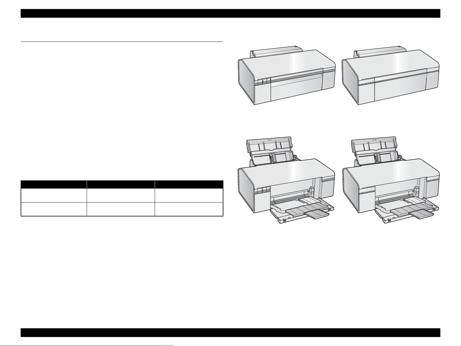
Paper Support & Stacker are Closed
Paper Support & Stacker are Opened
Epson Stylus Photo R280/R285/R290
Epson Artisan 50/
Epson Stylus Photo T50/T59/T60/P50
Epson Stylus Photo R280/R285/R290
Epson Artisan 50/
Epson Stylus Photo T50/T59/T60/P50
1.1 Features
Epson Stylus Photo R280/R285/R290 and Epson Artisan 50/Epson Stylus Photo T50/
T59/T60/P50 are single-function color ink-jet printers.
The main features are;
High speed & High quality
Maximum print resolution: 5760 (H) x 1440 (V) dpi
Newly developed F3 Mach Turbo II print head achieves higher print speed
than ever.
Six independent dye-ink cartridges enables high-resolution photo printing.
CD and DVD label printing are supported.
Borderless printing on specified EPSON brand paper is available.
Control panel
Simple design with three buttons and three indicators (LED).
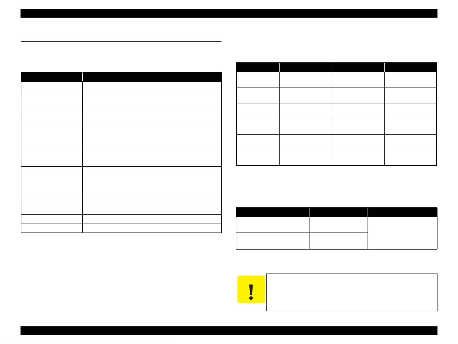
Dimensions and weight
Table 1-1. Dimensions and weight
Model
Epson Stylus Photo R280/
Epson Artisan 50/Epson Stylus
Note *1: Paper support and stacker are closed. Rubber feet are included.
R285/R290
Photo T50/T59/T60/P50
*2: Without ink cartridges
Dimensions (W x D x H) mm
450 x 282 x 187 5.4 kg
450 x 289 x 187 5.5 kg
*1
Weight
*2
Figure 1-1. External View
Chapter 1 Product Description 1.1 Features 9
Confidential
Epson Stylus Photo R280/R285/R290/Epson Artisan 50/Epson Stylus Photo T50/T59/T60/P50 Revision C
1.2 Printing Specifications
1.2.1 Basic Specifications
Table 1-2. Printer Specifications
Item Specifications
Print method On-demand ink jet
Nozzle configuration Black: 90 nozzles
Color: 90 nozzles x 5
(Cyan, Magenta, Yellow, Light Cyan, Light Magenta)
Print direction
Print resolution Horizontal x Vertical (dpi)
Control code
Internal font Character code:Alphanumeric with expanded graphics (PC437)
Paper feed method Friction feed, using one ASF (Auto Sheet Feeder)
Paper path Top feed, front out
Paper feed rates 110 msec (at 25.4 mm feed)
PF interval Programmable in 0.01764 mm (1/1440 inch) steps
Bi-directional minimum distance printing, unidirectional printing
• 360 x 180 • 720 x 540
• 360 x 360 • 720 x 720
• 720 x 360 • 5760 x 1440
• ESC/P Raster command
• EPSON Remote command
ASCII, 20H to 7FH only
Font: EPSON original font
Alphanumeric font: Courier
1.2.2 Ink Cartridge
The product numbers of the EPSON ink cartridges for this printer are shown below.
Table 1-3. Product No. of Ink Cartridges
Color EAI Euro Asia, CISMEA, Latin
Black
Cyan
Magenta
Yellow
Light Cyan
Light Magenta
T0771 (S)
T0781 (SS)
T0772 (S)
T0782 (SS)
T0773 (S)
T0783 (SS)
T0774 (S)
T0784 (SS)
T0775 (S)
T0785 (SS)
T0776 (S)
T0786 (SS)
T0801
T0802
T0803
T0804
T0805
T0806
Shelf life
Two years from production date (if unopened), six months after opening package.
Storage Temperature
Table 1-4. Storage Temperature
Situation Storage Temperature Limit
When stored in individual boxes
When installed in main unit
-20 oC to 40 oC
(-4oF to 104oF)
-20 oC to 40 oC
(-4oF to 104oF)
1 month max. at 40 oC (104oF)
T0811 (S)
T0821 (SS)
T0812 (S)
T0822 (SS)
T0813 (S)
T0823 (SS)
T0814 (S)
T0824 (SS)
T0815 (S)
T0825 (SS)
T0816 (S)
T0826 (SS)
Dimension
12.7 mm (W) x 68 mm (D) x 47 mm (H)
The ink cartridge cannot be refilled.
Do not use expired ink cartridges.
The ink in the ink cartridge freezes at -16 °C (3.2 oF). It takes
about three hours under 25 °C (77
o
F) until the ink thaws and
becomes usable.
Chapter 1 Product Description 1.2 Printing Specifications 10
Confidential
Epson Stylus Photo R280/R285/R290/Epson Artisan 50/Epson Stylus Photo T50/T59/T60/P50 Revision C
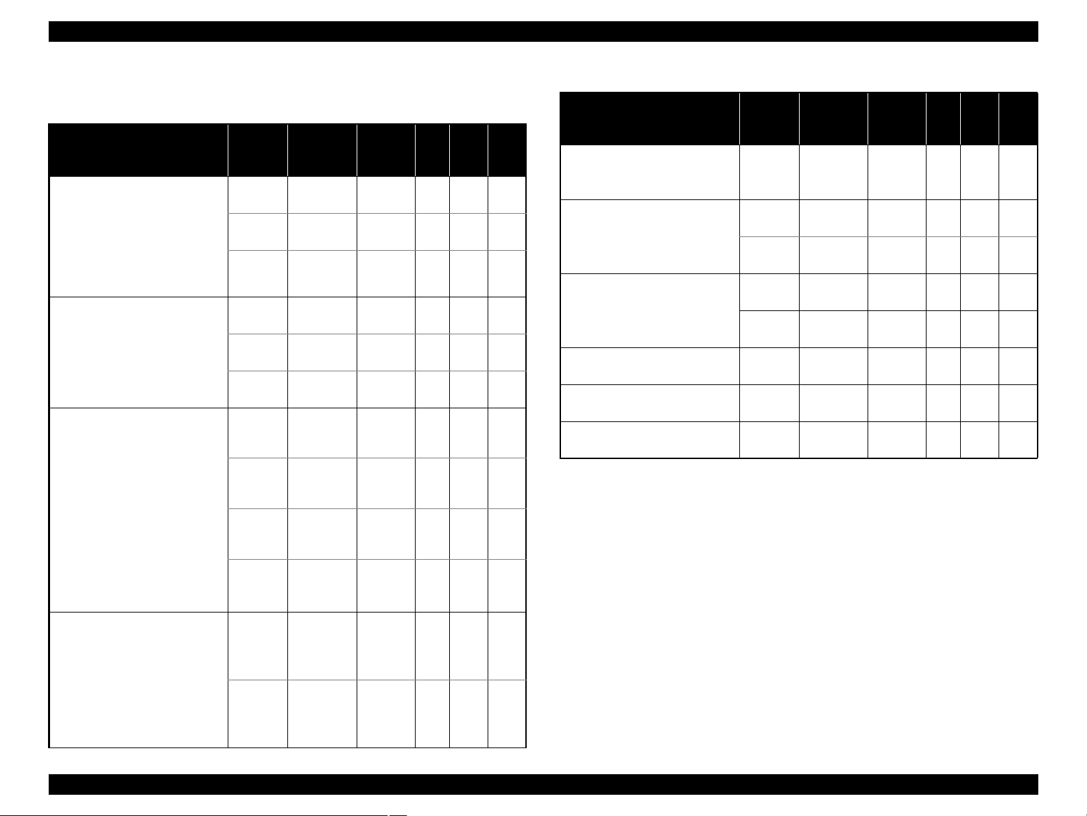
1.2.3 Print Mode
Media
• Plain paper
• Premium Bright White Paper
(EAI)
• Bright White Inkjet Paper
(others)
• Premium Ink Jet Plain Paper
(others)
• Ultra Premium Photo Paper
Glossy (EAI)
• Ultra Glossy Photo Paper
(others)
• Premium Photo Paper Glossy
(EAI)
• Premium Glossy Photo Paper
(others)
• Premium Photo Paper Semigloss (EAI)
• Premium Semigloss Photo
Paper (others)
• Ultra Premium Photo Paper
Luster (EAI)
• Photo Paper Glossy (EAI)
• Glossy Photo Paper (others)
• Premium Presentation Paper
Matte (EAI)
• Matte Paper Heavy-weight
(others)
• Premium Presentation Paper
Matte Double-sided (EAI)
• Double-Sided Matte paper
(others)
Table 1-5. Print Mode (Color)
Mode
Draft 360×180
Normal 360×360
Photo
Fine
Photo*
Photo*
Super
Photo
Fine 720×360
Photo*
Photo*
Super
Photo
Photo*
Super
Photo
Resolution
2
2
5760×1440
2
2
5760×1440
2
5760×1440
(H x V)
dpi
720×720
720×720
(1.5 pass)
720×720
(2.0 pass)
720×720
(1.5 pass)
720×720
(2.0 pass)
720×720
(2.0 pass)
Dot Size
(400cps)
(360cps)
(240cps)
(240cps)
(280cps)
(200cps)
(240cps)
(240cps)
(280cps)
(200cps)
(280cps)
(200cps)
(cps)*
Eco
MC2-1
MC1-1
MC1-2
MC2-2
MC1-5
MC1-1
MC1-2
MC2-2
MC1-5
MC2-2
MC1-5
1
Weave
Micro
Bi-d
ON OFF N/A
ON OFF N/A
ON ON N/A
ON ON OK
ON ON OK
ON ON OK
ON ON OK
ON ON OK
ON ON OK
ON ON OK
ON ON OK
ON ON OK
Border
less
—
Table 1-5. Print Mode (Color)
Media
Print
Mode
• Presentation Paper Matte (EAI)
• Photo Quality Inkjet Paper
Photo*
(others)
• Envelopes
Normal 360×360
Photo
Fine
• Iron-On Cool Peal Transfer
(EAI)
• Ion-On Cool Peal Transfer
Paper (Other)
• Photo Stickers
Normal
Photo
Fine
Photo*
• CD/DVD Super
Photo
• CD/DVD Premium Surface Super
Photo
Note *1: cps = character per second
*2: In Photo mode, either of 1.5 or 2.0 pass is selected depending on the paper size.
1.5 pass supported size: 4”x6”
2.0 pass supported size: 5”x7”, 8” x 10”, Letter, A4
*3: Epson Artisan 50/Epson Stylus Photo T50/T59/T60/P50 only
Resolution
2
*3
2
5760×1440
5760×1440
(H x V)
dpi
720×720
(2.0 pass)
720×720
360×360
720×720
720×720
(2.0 pass)
Dot Size
(cps)*
MC2-2
(280cps)
MC2-1
(360cps)
MC1-1
(240cps)
MC2-1
(360cps)
MC1-1
(240cps)
MC2-2
(280cps)
MC1-5
(200cps)
MC1-5
(200cps)
Bi-d
1
ON ON N/A
OFF OFF N/A
OFF ON N/A
ON OFF N/A
OFF ON N/A
ON ON N/A
ON ON N/A
ON ON N/A
Micro
Weave
Border
—
less
Chapter 1 Product Description 1.2 Printing Specifications 11
Confidential
Epson Stylus Photo R280/R285/R290/Epson Artisan 50/Epson Stylus Photo T50/T59/T60/P50 Revision C
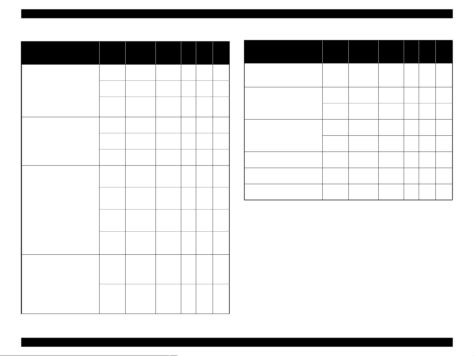
Table 1-6. Print Mode (Monochrome)
Media
• Plain paper
• Premium Bright White Paper
(EAI)
• Bright White Inkjet Paper
(others)
• Premium Ink Jet Plain Paper
(others)
• Ultra Premium Photo Paper
Glossy (EAI)
• Ultra Glossy Photo Paper
(others)
• Premium Photo Paper Glossy
(EAI)
• Premium Glossy Photo Paper
(others)
• Premium Photo Paper Semigloss (EAI)
• Premium Semigloss Photo
Paper (others)
• Ultra Premium Photo Paper
Luster (EAI)
• Photo Paper Glossy (EAI)
• Glossy Photo Paper (others)
• Premium Presentation Paper
Matte (EAI)
• Matte Paper Heavy-weight
(others)
• Premium Presentation Paper
Matte Double-sided (EAI)
• Double-Sided Matte paper
(others)
Mode
Resolution
(H x V)
dpi
Draft 360×180
Normal 360×360
Photo
Fine
Photo*
Photo*
Super
Photo
2
2
5760×1440
720×720
720×720
(1.5 pass)
720×720
(2.0 pass)
Fine 720×360
720×720
2
Photo*
Photo*
Super
Photo
Photo*
Super
Photo
2
5760×1440
2
5760×1440
(1.5 pass)
720×720
(2.0 pass)
720×720
(2.0 pass)
Dot Size
(cps)*
Eco
(400cps)
MC2-1
(360cps)
MC1-1
(240cps)
MC1-2
(240cps)
MC2-2
(280cps)
MC1-5
(200cps)
MC1-1
(240cps)
MC1-2
(240cps)
MC2-2
(280cps)
MC1-5
(200cps)
MC2-2
(280cps)
MC1-5
(200cps)
1
Weave
Micro
Bi-d
ON OFF N/A
ON OFF N/A
ON ON N/A
ON ON OK
ON ON OK
ON ON OK
ON ON OK
ON ON OK
ON ON OK
ON ON OK
ON ON OK
ON ON OK
Border
less
—
Table 1-6. Print Mode (Monochrome)
Media
Print
Mode
• Presentation Paper Matte (EAI)
• Photo Quality Inkjet Paper
Photo*
(others)
• Envelopes
Normal 360×360
Photo
Fine
• Iron-On Cool Peal Transfer
(EAI)
• Ion-On Cool Peal Transfer
Paper (Other)
• Photo Stickers
Normal
Photo
Fine
Photo*
• CD/DVD Super
Photo
• CD/DVD Premium Surface Super
Photo
Note *1: cps = character per second
*2: In Photo mode, either of 1.5 or 2.0 pass is selected depending on the paper size.
1.5 pass supported size: 4”x6”
2.0 pass supported size: 5”x7”, 8” x 10”, Letter, A4
*3: Epson Artisan 50/Epson Stylus Photo T50/T59/T60/P50 only
Resolution
2
*3
2
5760×1440
5760×1440
(H x V)
dpi
720×720
(2.0 pass)
720×720
360×360
720×720
720×720
(2.0 pass)
Dot Size
(cps)*
MC2-2
(280cps)
MC2-1
(360cps)
MC1-1
(240cps)
MC2-1
(360cps)
MC1-1
(240cps)
MC2-2
(280cps)
MC1-5
(200cps)
MC1-5
(200cps)
Bi-d
1
ON ON N/A
OFF OFF N/A
OFF ON N/A
ON OFF N/A
OFF ON N/A
ON ON N/A
ON ON N/A
ON ON N/A
Micro
Weave
Border
—
less
Chapter 1 Product Description 1.2 Printing Specifications 12
Confidential

Epson Stylus Photo R280/R285/R290/Epson Artisan 50/Epson Stylus Photo T50/T59/T60/P50 Revision C
1.2.4 Supported Paper
The table below lists the paper type and sizes supported by the printer. The supported paper type and sizes vary depending on destinations (between EAI, EUR, and Asia)
Table 1-7. Supported Paper
Paper Name Paper Size
Legal 215.9 x 355.6 mm (8.5”x14”)
Letter 215.9 x 279.4 mm (8.5”x11”) Y — Y — Y —
A4 210 x 297 mm (8.3”x11.7”) Y — Y — Y —
B5 182 x 257 mm (7.2”x10.1”) — — Y — Y —
Plain paper
Premium Inkjet Plain Paper A4 210 x 297 mm (8.3”x11.7”) 0.11 80 21 — — Y — Y —
Premium Bright White Paper (EAI)
Bright White Inkjet Paper (others) A4 210 x 297 mm (8.3”x11.7”) 0.13 92.5 25 — — Y — Y —
Ultra Premium Photo Paper Glossy (EAI)
Ultra Glossy Photo Paper (others)
Premium Photo Paper Glossy (EAI)
Premium Glossy Photo Paper (others)
Photo Paper Glossy (EAI)
Glossy Photo Paper (others)
A5 148 x 210 mm (5.8”x8.3”) — — Y — Y —
Half Letter 139.7 x 215.9 mm (5.5”x8.5”) Y — — — — —
A6 105 x 148 mm (4.1”x5.8”) Y — Y — Y —
User Defined
89 x 127- 329 x 1117.6 mm
(3.56”x 5.08” — 13.16”x44.7”)
Letter 215.9 x 279.4 mm (8.5”x11”) 0.11 90 24 Y — — — — —
Letter 215.9 x 279.4 mm (8.5”x11”)
A4 210 x 297 mm (8.3”x11.7”) — — Y Y Y
8” x 10” 203.2 x 254 mm Y Y — — — —
5” x 7” 127 x 178 mm Y Y Y Y — —
4” x 6” 101.6 x 152.4 mm Y Y Y Y Y
Letter 215.9 x 279.4 mm (8.5”x11”)
A4 210 x 297 mm (8.3”x11.7”) Y
8” x 10” 203.2 x 254 mm Y Y — — — —
5” x 7” 127 x 178 mm Y Y Y Y Y Y
”
x 6
”
4
101.6 x 152.4 mm Y Y Y Y Y Y
16:9 wide 102 x 181 mm (4”x7.11”) Y
Letter 215.9 x 279.4 mm (8.5”x11”)
A4 210 x 297 mm (8.3”x11.7”) Y Y Y Y Y Y
5” x 7” 127 x 178 mm — — Y Y — —
4” x 6” 101.6 x 152.4 mm Y Y Y Y Y Y
.
Thickness Weight EAI EUR Asia
*1
*1
*1
*1
mm g/m2lb. P
B
P
B
*1
P
Y-Y-Y-
0.08-0.11 64-90 17-24
Y — Y — Y —
Y Y — — — —
*2
0.30 290 77
*2
YY—-
*3
*3
Y
Y Y Y Y
0.27 255 68
*4
*4
Y
Y Y
*4
— —
YY—-
0.25 258 68
*1
B
*2
Y
*2
Y
Chapter 1 Product Description 1.2 Printing Specifications 13
Confidential

Epson Stylus Photo R280/R285/R290/Epson Artisan 50/Epson Stylus Photo T50/T59/T60/P50 Revision C
Table 1-7. Supported Paper
Paper Name Paper Size
A4 210 x 297 mm (8.3”x11.7”)
Photo Paper (others)
*4
5” x 7” 127 x 178 mm — — Y Y
4” x 6” 101.6 x 152.4 mm — — Y Y Y Y
Letter 215.9 x 279.4 mm (8.5”x11”)
Premium Photo Paper Semi-gloss (EAI)
Premium Semigloss Photo Paper (others)
A4 210 x 297 mm (8.3”x11.7”) — — Y Y Y Y
4” x 6” 101.6 x 152.4 mm Y Y Y Y Y Y
Ultra Premium Photo Paper Luster Letter 215.9 x 279.4 mm (8.5”x11”) 0.27 250 66 Y Y — — — —
Letter 215.9 x 279.4 mm (8.5”x11”)
Premium Presentation Paper Matte (EAI)
Matte Paper Heavy-weight (others)
A4 210 x 297 mm (8.3”x11.7”) — — Y Y Y Y
8” x 10” 203.2 x 254 mm Y Y — — — —
Premium Presentation Paper Matte Double-sided
(EAI)
Double-sided Matte Paper (others)
Presentation Paper Matte (EAI)
Photo Quality Inkjet Paper (others)
Letter 215.9 x 279.4 mm (8.5”x11”)
A4 210 x 297 mm (8.3”x11.7”) — — Y — Y —
Letter 215.9 x 279.4 mm (8.5”x11”)
A4 210 x 297 mm (8.3”x11.7”) Y — Y — Y —
#10 104.8 x 241.3 mm (4.125”x9.5”)
Envelopes
#DL 110 x 220 mm — — Y — Y —
#C6 114 x 162 mm — — Y — Y —
Iron-On Cool Peal Transfer (EAI)
Iron-On Cool Peal Transfer Paper (Other)
Photo Stickers 16
Letter 215.9 x 279.4 mm (8.5”x11”)
A4 210 x 297 mm (8.3”x11.7”) — — Y — Y —
A6 105 x 148 mm (4.1”x5.8”) 0.19 — — — — — Y —
Photo Stickers 4 A6 105 x 148 mm (4.1”x5.8”) 0.19 — — — — — Y
CD/DVD
CD/DVD Premium Surface
ø12cm ø12cm — — Y — Y — Y —
ø8cm ø8cm — -Y-Y-Y-
Thickness Weight EAI EUR Asia
*1
*1
*1
*1
mm g/m2lb. P
B
P
B
*1
P
— — YYYY
0.24 190 51
Y Y — — — —
0.27 250 66
Y Y — — — —
0.23 167
44
Y——
0.22 185 49
0.12 102 27
Y——
Y-Y-Y-
— 75-90 20-24
0.14 130 35
Y — — — — —
*3
B
*1
—
Note *1: “Y” in the “P” column stands for “the paper type/size is Supported”. “Y” in the “B” column stands for “Borderless printing is available”.
*2: Singapore, Taiwan, Australia only
*3: Epson Stylus Photo R280/R285/R290 only
*4: Epson Artisan 50/Epson Stylus Photo T50/T59/T60/P50 only
Chapter 1 Product Description 1.2 Printing Specifications 14
Confidential
Epson Stylus Photo R280/R285/R290/Epson Artisan 50/Epson Stylus Photo T50/T59/T60/P50 Revision C
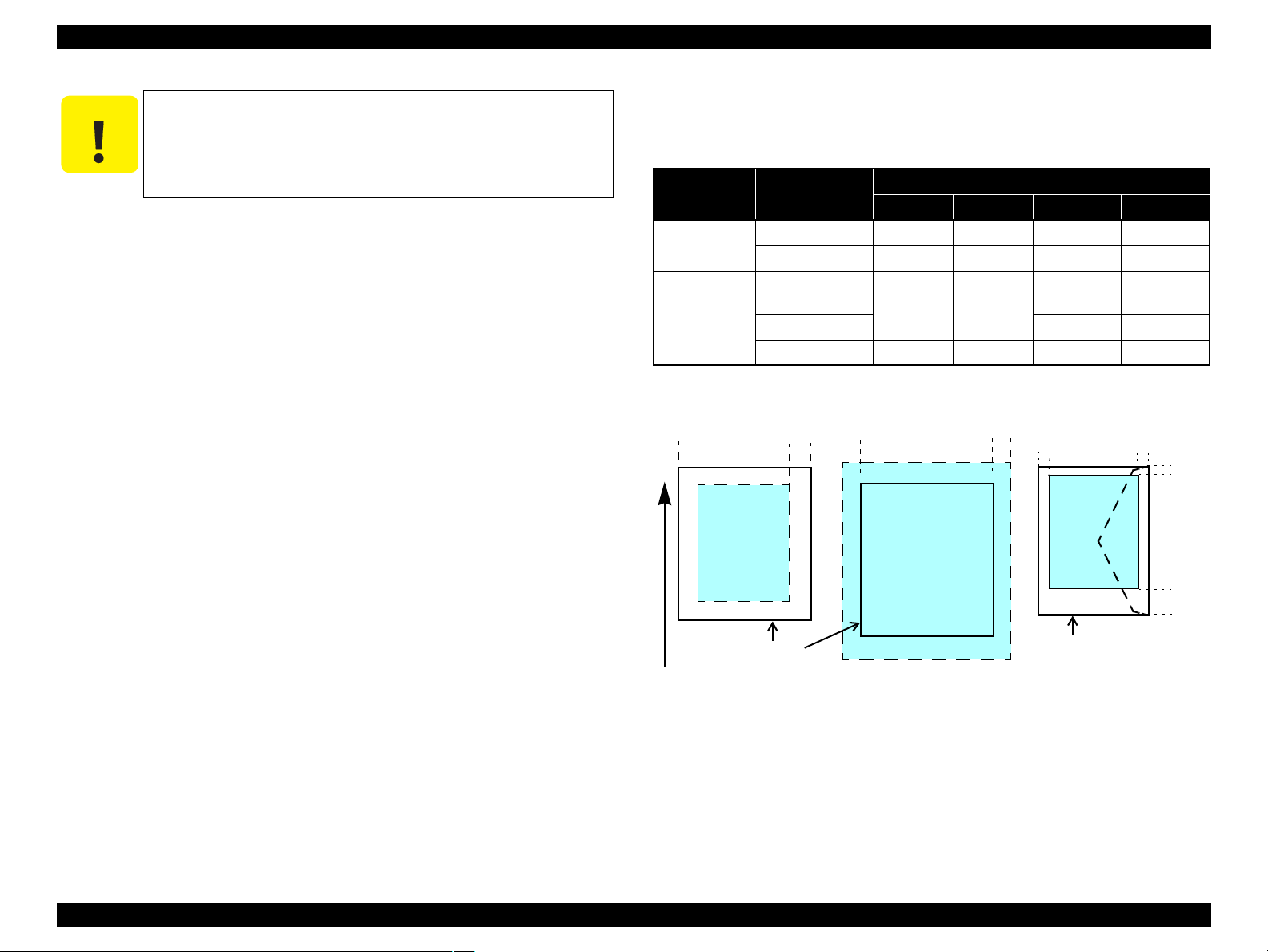
Print Area
LM RM
TM
BM
BM
Cut Sheet (Standard)
Cut Sheet (Borderless)
Paper Size
LM
RM
TM
BM
Print Area
LM RM
Print Area
Envelope
Paper Size
TM
Paper Feed Direction
Make sure the paper is not wrinkled, fluffed, torn, or folded.
The curve of paper must be 5 mm or below.
When printing on an envelope, be sure the flap is folded neatly.
Do not use the adhesive envelopes.
Do not use double envelopes and cellophane window envelopes.
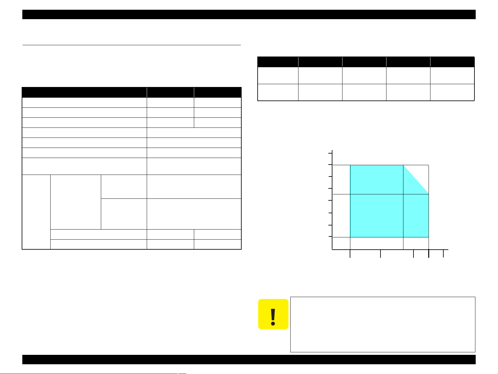
1.2.5 Printing Area
The printing area for this printer is shown below.
Table 1-8. Printing Area (Margins)
Print Mode Paper Size
Left Right Top Bottom
Standard print Any size 3 mm 3 mm 3 mm 3 mm
Envelope 5 mm 5 mm 3 mm 20 mm
Borderless
print
A4/Letter to
5” x 7”
2.54 mm* 2.54 mm*
4” x 6” 1.34 mm* 2.54 mm*
Card 1.83mm* 1.83mm* 2.54mm* 3.53mm*
Note * : The margins for Borderless print are margins that bleed off the edges of paper.
Margin
2.96 mm* 4.02 mm*
Chapter 1 Product Description 1.2 Printing Specifications 15
Figure 1-2. Printing Area
Confidential
Epson Stylus Photo R280/R285/R290/Epson Artisan 50/Epson Stylus Photo T50/T59/T60/P50 Revision C
1.3 Interface
The printer has a USB interface of the following specification.
Standards
“Universal Serial Bus Specifications Revision 2.0”
“Universal Serial Bus Device Class Definition for Printing Devices Version 1.1”
Transfer rate: 480 Mbps (High Speed Device)
Data format: NRZI
Compatible connector: USB Series B
Recommended cable length: 2 [m] or less
Device ID
Table 1-9. Epson Stylus Photo R280/R285/R290
Product
Name
Epson Stylus
Photo R280
Epson Stylus
Photo R285
Epson Stylus
Photo R290
When IEEE 1284.4 is Enabled When IEEE 1284.4 is Disabled
MFG:EPSON;
CMD:ESCPL2,BDC,D4,D4PX;
MDL:Stylus[SP]Photo[SP]R280;
CLS:PRINTER;
DES:EPSON[SP]Stylus[SP]Photo
[SP]R280;
MFG:EPSON;
CMD:ESCPL2,BDC,D4,D4PX;
MDL:Stylus[SP]Photo[SP]R285;
CLS:PRINTER;
DES:EPSON[SP]Stylus[SP]Photo
[SP]R285;
MFG:EPSON;
CMD:ESCPL2,BDC,D4,D4PX;
MDL:Stylus[SP]Photo[SP]R290;
CLS:PRINTER;
DES:EPSON[SP]Stylus[SP]Photo
[SP]R290;
MFG:EPSON;
CMD:ESCPL2,BDC;
MDL:Stylus[SP]Photo[SP]R280;
CLS:PRINTER;
MFG:EPSON;
CMD:ESCPL2,BDC;
MDL:Stylus[SP]Photo[SP]R285;
CLS:PRINTER;
MFG:EPSON;
CMD:ESCPL2,BDC;
MDL:Stylus[SP]Photo[SP]R290;
CLS:PRINTER;
Table 1-10. Epson Artisan 50/Epson Stylus Photo T50/T59/T60/P50
Product
Name
Epson Artisan 50/
Epson Stylus
Photo T50/T59/
T60/P50
Note : The “Model Name” is replaced as shown in the following table.
North America Artisan 50
West Euro Epson Stylus Photo P50
Asia/Pacific/South America/CISMEA Epson Stylus Photo T50
Singapore/Korea Epson Stylus Photo T60
When IEEE 1284.4 is Enabled When IEEE 1284.4 is Disabled
@EJL<SP>ID<CR><LF>
MFG:EPSON;
CMD:ESCPL2,BDC,D4,D4PX;
MDL:Model Name;
CLS:PRINTER;
DES:EPSON<SP>Model Name;
CID:EpsonStd2;
Destination Model Name
@EJL<SP>ID<CR><LF>
MFG:EPSON;
CMD:ESCPL2,BDC;
MDL:Model Name;
CLS:PRINTER;
DES:EPSON<SP>Model Name;
CID:EpsonStd2;
Chapter 1 Product Description 1.3 Interface 16
Confidential
Epson Stylus Photo R280/R285/R290/Epson Artisan 50/Epson Stylus Photo T50/T59/T60/P50 Revision C
10/50
27/80
30/86 35/95 40/10420/68
Temperature (°C/°F)
20
30
40
50
90
80
70
60
Humidity (%)
1.4 General Specifications
1.4.1 Electrical Specifications
Primary power input
Table 1-11. Primary Power Specifications
Item 100-120V model 220-240V model
Rated power supply voltage 100 to 120 VAC 220 to 240 VAC
Input voltage range 90 to 132 VAC 198 to 264 VAC
Rated current 0.6 A (max. 1.0 A) 0.3 A (max. 0.5 A)
Rated frequency 50 to 60 Hz
Input frequency range 49.5 to 60.5 Hz
Insulation resistance 3000 V (for one minute)
Energy conservation
Epson Stylus
Photo R280/
Printing
Power
consumpt
ion
Note : If the printer is not operated for more than three minutes, the printer shifts into the
(ISO10561 Letter
Pattern)
Sleep mode Approx. 1.0 W Approx. 1.2 W
Standby mode
standby mode and reduces the current to the motor to conserve power.
R285/R290
Epson Artisan 50/
Epson Stylus
Photo T50/T59/
T60/P50
(power-off) Approx. 0.2 W Approx. 0.3 W
International Energy Star Program
compliant
Approx. 12 W
Approx. 13 W
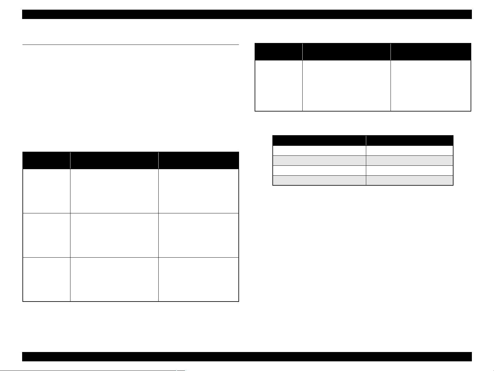
1.4.2 Environmental Conditions
Table 1-12. Environmental Conditions
Condition Temperature
Operating
Storage*3
(unpacked)
Note *1: The combined Temperature and Humidity conditions must be within the blue-shaded
range in
*2: No condensation
*3: Non-operating with unpacked.
*4: Must be less than 1 month under 40°C.
10 to 35°C
(50 to 95°F)
-20 to 40°C*
(-4°F to 104°F)
Fig.1-3.
*1
4
Humidity
20
to 80%
to 85%
5
*1,2
Shock Vibration
1G
(1 msec or less)
2G
(2 msec or less)
10 to 55Hz
10 to 55Hz
0.15G,
0.50G,
Chapter 1 Product Description 1.4 General Specifications 17
Figure 1-3. Temperature/Humidity Range
When returning the repaired printer to the customer, make sure
the Printhead is covered with the cap and the ink cartridge is
installed.
If the Printhead is not covered with the cap when the printer is
off, turn on the printer with the ink cartridge installed, make
sure the Printhead is covered with the cap, and then turn the
printer off.
Confidential

Epson Stylus Photo R280/R285/R290/Epson Artisan 50/Epson Stylus Photo T50/T59/T60/P50 Revision C
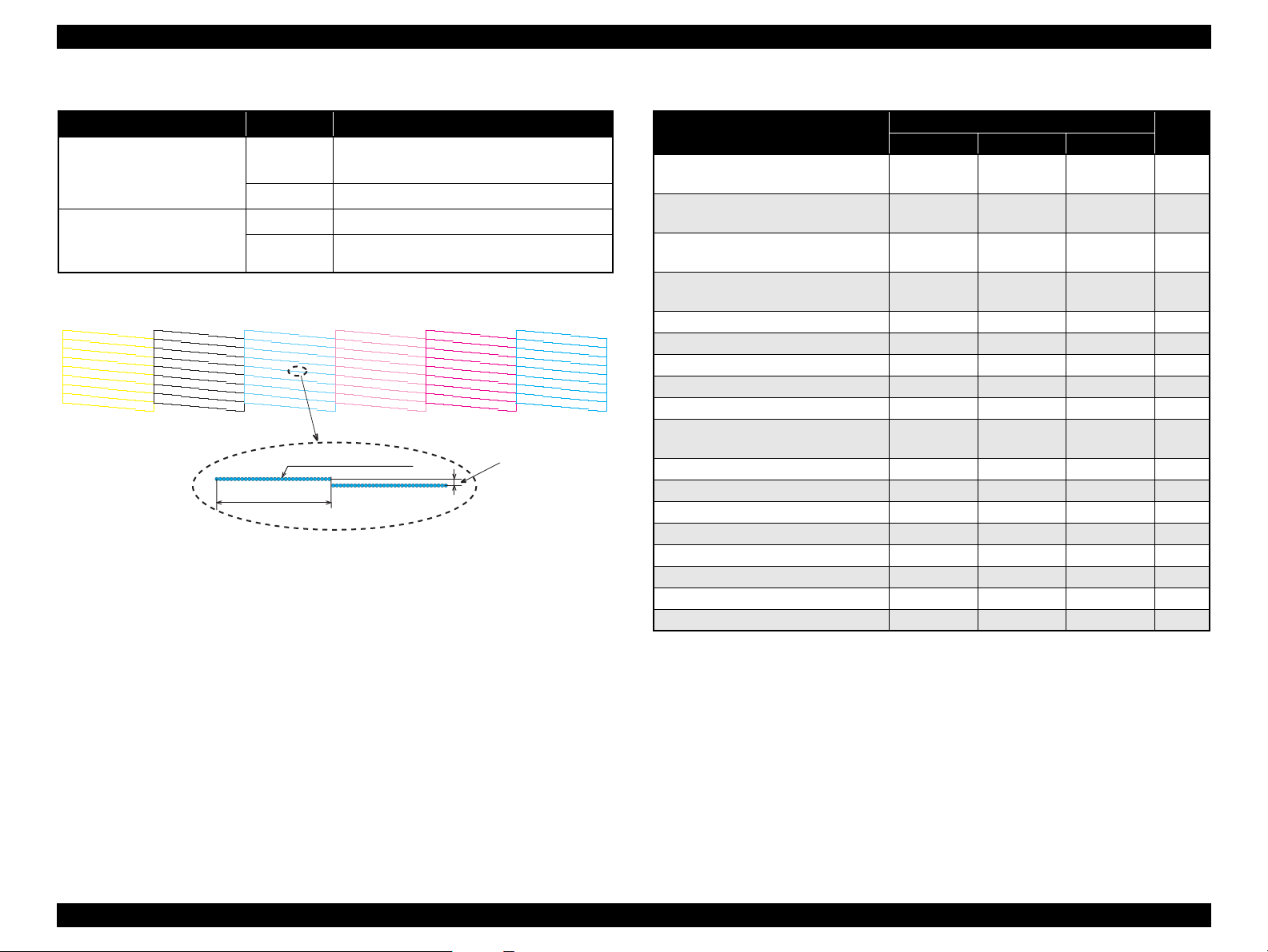
1.4.3 Durability
Total print life: Black 16,000 pages (A4, 3.5% duty),
Color 10,000 pages (A4, 5% duty),
or five years which ever comes first
Printhead: Six billions shots (per nozzle) or five years which ever comes
first
1.4.4 Acoustic Noise
Epson Stylus Photo R280/R285/R290: 36 dB
Epson Artisan 50/Epson Stylus Photo T50/T59/T60/P50: 34.7 dB or less
(when printing from PC, on Premium Glossy Photo Paper, in highest quality)
1.4.5 Safety Approvals (Safety standards/EMI)
USA UL60950-1
FCC Part15 Subpart B Class B
Canada CAN/CSA-C22.2 No.60950-1
CAN/CSA-CEI/IEC CISPR 22 Class B
Mexico NOM-019-SCFI-1998
Taiwan CNS13438 Class B
CNS14336
EU EN60950-1
EN55022 Class B
EN61000-3-2, EN61000-3-3
EN55024
Germany EN60950-1
Russia GOST-R (IEC60950-1, CISPR 22)
Singapore IEC60950-1
Korea K60950-1
KN22 Class B
KN61000-4-2/-3/-4/-5/-6/-11
China GB4943
GB9254 Class B, GB17625.1
Argentina IEC60950-1
Australia AS/NZS CISPR22 Class B
Hong Kong IEC60950-1
*
*
NOTE * :
Epson Stylus Photo R280/R285/R290 only
Chapter 1 Product Description 1.4 General Specifications 18
Confidential
Epson Stylus Photo R280/R285/R290/Epson Artisan 50/Epson Stylus Photo T50/T59/T60/P50 Revision C
Power Button Paper ButtonInk Button
Power LED Paper LEDInk LED
Power Button Paper ButtonInk Button
Power LED
Paper LED
Ink LED
Epson Stylus Photo
R280/R285/R290
Epson Artisan 50/Epson Stylus
Photo T50/T59/T60/P50
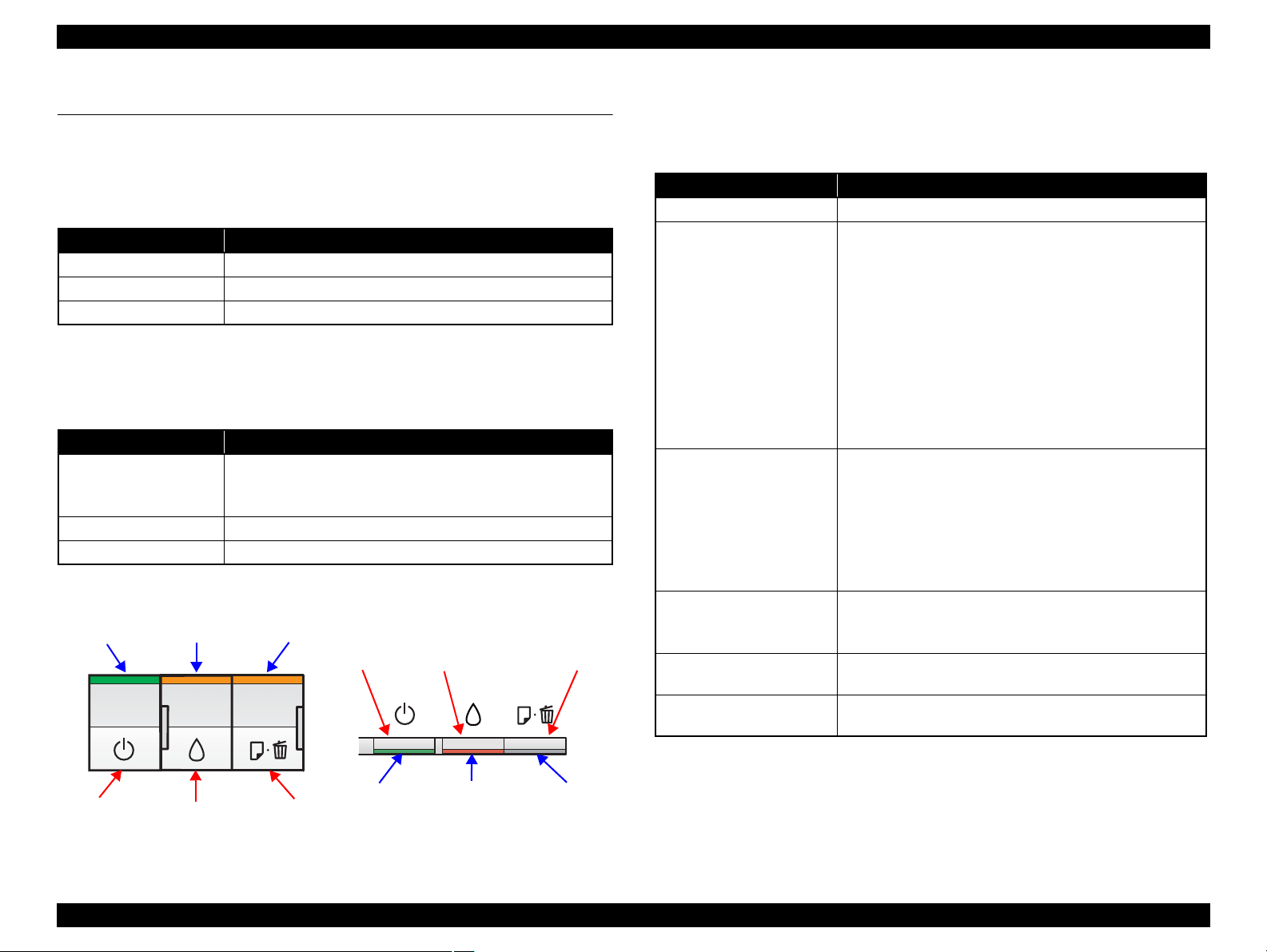
1.5 Operation Buttons & Indicators (LEDs)
1.5.1 Operation Buttons
The printer has the following three operation buttons.
Table 1-13. Operation Buttons
Button Function
Power Turns the power ON/OFF.
Ink Runs a sequence of ink cartridge replacement or cleaning.
Paper Feeds or ejects paper.
1.5.2 Indicators (LEDs)
Three indicators (LEDs) are provided to indicate settings or printer status.
Table 1-14. Indicators (LEDs)
LED Function
Lights at power-on.
Power LED (green)
Ink LED (orange)*
Paper LED (orange)*
Note *1:The Ink LED and Paper LED stay OFF when printing from PC.
*2:See Table 1-17 “Indicators (LEDs) Function” for the LED status at error occurrence.
1
Flashes during some sequence is in progress.
Flashes at high speed during power-OFF sequence.
Lights or flashes when an ink-related error occurs.*
1
Lights or flashes when an paper- or CD-R-related error occurs.*
1.5.3 Operation Buttons & LEDs Functions
Detailed information on the buttons and LEDs functions are listed below.
Table 1-15. Operation Button Functions (During Normal Operation)
Button Function
Power • Turns the power ON/OFF
• Runs a sequence of ink cartridge replacement. The carriage
moves to set the ink cartridge to the position for
replacement.
• Moves the carriage to set the ink cartridge to the ink check
position when ink level low, ink out, or no ink cartridge
Ink
2
2
Paper
Ink
(when held for three seconds
or longer)
Power + Paper *
(combination)
Power + Ink *
(combination)
Note 1: First press the Paper button and then Power button. The printer will turn On and print
the nozzle check pattern.
2: First press the Power button and then Ink button. Hold them for seven seconds.
1
2
error has occurred.
• When an ink cartridge has been set in the ink check
position, moves the carriage to set the cartridge to the
position for replacement, or to set another cartridge to the
ink check position.
• When an ink cartridge has been set in the ink replacement
position, moves the carriage to the home position.
• Feeds or ejects paper.
• Recovers from a multi-feed error and feeds paper to restart
the print job.
• Feeds paper when paper is loaded after a no-paper error
occurs.
• Ejects a jammed paper when a paper jam error occurs.
• Cancels the print job during printing.
• Runs a head cleaning.
• Runs a sequence of ink cartridge replacement when ink
level low, ink out, or no ink cartridge error has occurred.
• Prints a nozzle check pattern*3.
• Forcefully turns the power OFF.
Chapter 1 Product Description 1.5 Operation Buttons & Indicators (LEDs) 19
Figure 1-4. Buttons & LEDs
3: The nozzle check pattern printed by the printer is shown in Figure 1-5.
Confidential
Epson Stylus Photo R280/R285/R290/Epson Artisan 50/Epson Stylus Photo T50/T59/T60/P50 Revision C
11
1
31
21
51
41
71
61
81
20
10
40
30
60
50
80
70
90
11
1
31
21
51
41
71
61
81
20
10
40
30
60
50
80
70
90
11
1
31
21
51
41
71
61
81
20
10
40
30
60
50
80
70
90
11
1
31
21
51
41
71
61
81
20
10
40
30
60
50
80
70
90
11
1
31
21
51
41
71
61
81
20
10
40
30
60
50
80
70
90
11
1
31
21
51
41
71
61
81
20
10
40
30
60
50
80
70
90
Note : The numbers shown in the figure are nozzle numbers. The numbers and color names
are not printed on an actual nozzle check pattern.
720 dpi MC1-1
32 dots
0.282 mm (1/90 inch)
Yellow Black Light Cyan Light Magenta CyanMagenta
Table 1-16. Operation Button Functions (During CD-R Printing)
Button CD-R Tray Function
Paper
Ink
(including when held
for three seconds or longer)
In
• Recovers form a CD-R tray error.
• Cancels the print job during printing.
Out • Recovers form a CD-R jam error.
In • Does not function.
Out
• Same as during normal operation.
Figure 1-5. Nozzle Check Pattern
Table 1-17. Indicators (LEDs) Function
Printer Status
Power OFF
Power Ink Paper
Flashes at
high speed
Fatal error OFF
Maintenance request OFF
CD-R guide error —
Indicators (LEDs)
OFF OFF 1
Flashes at
high speed
Flashes at
high speed
Flashes
alternately 2
Flashes at
high speed
alternately 1
Flashes 2 4
Flashes
Paper (CD-R) jam — — Flashes 5
Multi-feed error — — ON 6
No paper error — — ON 6
CD-R Tray error — — ON 6
Cover open error — Flashes 2 Flashes 2 6
Ink cartridge replacement is in
progress
Flashes — — 7
Ink sequence is in progress Flashes — — 8
CSIC error — ON — 9
No ink cartridge error or ink-out error — ON — 9
During feeding or ejecting paper Flashes — — 10
Data processing Flashes — — 10
Ink level low — Flashes — 11
Power ON ON — — 12
Reset request*
2
ON ON ON —
Pri-
ority*
1
2
3
Chapter 1 Product Description 1.5 Operation Buttons & Indicators (LEDs) 20
Note : —: No change
Flash: Repeats turning On and Off every 1.25 seconds.
Flash 2: [Epson Stylus Photo R280/R285/R290]
Repeats On for 0.5 seconds, Off for 0.5 seconds,
On for 0.5 seconds, and Off for 1.0 second.
[Epson Artisan 50/Epson Stylus Photo T50/T59/T60/P50]
Flash at high speed: Repeats turning On and Off every 0.5 seconds.
Flashes alternately 1: same as the “Flash”
Flashes alternately 2: Repeats turning Off and On every 1.25 seconds.
Repeats On for 1.25 seconds, Off for 1.25 seconds,
On for 0.5 seconds, and Off for 1.0 second.
Note *1: When two or more errors occur at the same time, the one with higher priority will be
indicated.
*2: The all LEDs light for 0.2 seconds when a reset request is received.
Confidential

Epson Stylus Photo R280/R285/R290/Epson Artisan 50/Epson Stylus Photo T50/T59/T60/P50 Revision C
1.5.4 Errors & Remedies
Table 1-18. Errors & Remedies
Error Error Remedies
Fatal error A mechanical error has occurred. Turn the power Off and back it On.
Maintenance
request
CD-R guide error
Paper jam
No paper
Multi-feed
CD-R Tray error
Ink-out The cartridge has run out of ink. Replace the ink cartridge.
No ink cartridge
Wrong ink
cartridge
Note : For more information on the remedies, see 3.2 Error Indications and Fault
Occurrence Causes.
Note *1: When the CD-R guide (stacker) is attached to the upper position (CD-R print
position), attach the guide to the lower position and press the Paper button.
*2: When the CD-R tray has been inserted, remove the CD-R tray and press the Ink
button.
Waste ink pads need to be
replaced.
• The CD-R guide (stacker)
position does not match with
Replace the waste ink pads and
reset the counter.
Attach the CD-R guide (stacker) to
the proper position.
the print job.
• The CD-R guide (stacker) is in
the CD-R printing position at
power-ON.
A paper jam has occurred. <When printing on paper>
Remove the jammed paper and
press the Paper button.*
1
<When printing on CD-R>
Remove the jammed CD-R tray
and press the Paper button.
Failed to feed paper. Load paper correctly and press the
1
1
Multiple sheets of paper were fed
at the same time.
Paper button.*
Press the Paper button to eject the
multiple sheets.*
A CD-R tray were not detected. Insert the CD-R tray and press the
Paper button.
*2
Ink cartridge(s) was not detected. Replace the ink cartridge.
*2
Chapter 1 Product Description 1.5 Operation Buttons & Indicators (LEDs) 21
Confidential

OPERATING PRINCIPLES
CHAPTER
2
Confidential
Epson Stylus Photo R280/R285/R290/Epson Artisan 50/Epson Stylus Photo T50/T59/T60/P50 Revision C
PF Encoder Sensor APG Sensor
ASF Unit
CR Motor
PF Motor
LD Roller
CR Encoder
Sensor
PE Sensor
PF Roller Shaft
APG Unit
Ink System
CR Lock Lever
EJ Roller Shaft
PW Sensor
Cap ASSY
CR Shaft
CDR Guide
Sensor
Printhead
CR Unit
EJ Frame
CDR Tray
Sensor
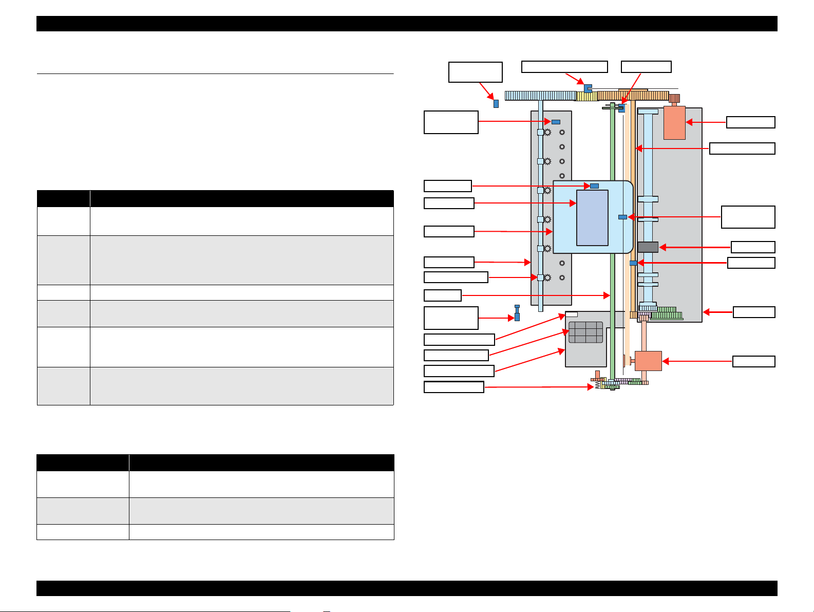
2.1 Overview
This chapter describes the operating principles of the printer mechanism and electric
circuit boards of Stylus Photo R280/R285/R290 and Epson Artisan 50/Epson Stylus
Photo T50/T59/T60/P50.
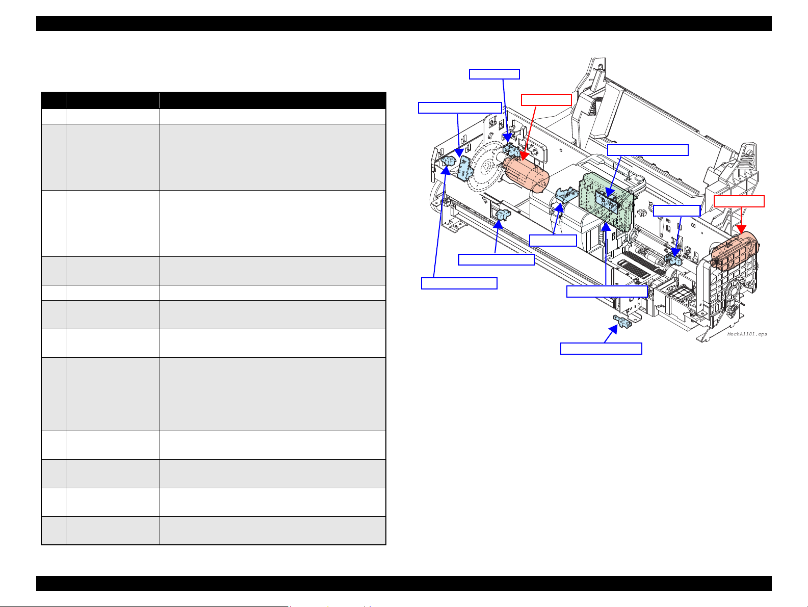
2.1.1 Printer Mechanism
The main components of the printer mechanism are shown in the table below.
Table 2-1. Printer Mechanism Main Components
Component Function
CR Unit
APG Unit
PF Unit Rotates the PF roller shaft to feed paper being powered by the PF motor.
ASF Unit
EJ Unit
Ink System
The main control boards are shown in the table below.
Main Board
Power Supply Board
(P/S ASSY)
Panel Board Located inside the Panel Unit and controls the operation panel.
Chapter 2 Operating Principles 2.1 Overview 23
Moves along the CR shaft to print on paper being powered by the CR motor.
The unit includes Printhead, PW sensor, and CR encoder sensor.
Moves the carriage upward/downward to adjust the platen gap being powered by
the PF motor. There are 4 preset levels of platen gap and the unit moves the
carriage to one of the levels according to the current carriage position detected by
the APG sensor.
Being powered by the PF motor, feeds paper loaded on the ASF into the printer
mechanism.
Being powered by the PF motor, ejects paper or the CDR tray.
The EJ frame moves corresponding to the stacker position so that the frame
matches with the paper size.
Located on the right side of the printer mechanism. Covers the printhead with the
cap holder when the printhead is not used, and draws waste ink out of the
printhead. The waste ink is sent to the Waste Ink Tray through the waste ink tube.
Table 2-2. Main Control Boards
Board Function
Located on top of the printer mechanism and controls all over the
printer operations.
Located on the Lower Housing and generates required voltages for the
printer using the power supplied from the AC power line.
Cover Open
Cover Open
Sensor
Sensor
Figure 2-1. Printer Mechanism Diagram
Confidential
Epson Stylus Photo R280/R285/R290/Epson Artisan 50/Epson Stylus Photo T50/T59/T60/P50 Revision C
APG Sensor
CR Motor
PF Motor
PF Encoder Sensor
CDR Tray Sensor
CR Encoder Sensor
PE Sensor
PW Sensor
Cover Open Sensor
CDR Guide Sensor
CR Contact Module
2.1.2 Motors & Sensors
No. Motor/Sensor Name Function
1 Printhead F3-MACH Turbo2 head (6 colors x 90 nozzles)
2 CR motor
3PF motor
4 PE sensor
5 CR Contact module Ink cartridge detection (CSIC)
6 CR Encoder sensor
7 PF Encoder sensor
8 PW sensor
9 APG sensor
10 CDR Guide sensor
11 CDR Tray sensor
12 Cover Open sensor
Table 2-3. List of Motors & Sensors
Type: DC motor
Drive voltage: 42V DC
Ω ± 10%
Ω ± 10%
Coil resistance: 22.7
Inductance: 17.5mH ± 25%
Drive method: PWM constant-current chopping
Type: DC motor
Drive voltage: 42V DC
Coil resistance: 21.2
Inductance: 17.2mH (1 kHz)
Drive method: PWM
Detecting items: paper end, leading edge of paper
Type: Transmissive photo interrupter
Type: Transmissive photo interrupter
Resolution: 180 pulse/inch
Type: Transmissive photo interrupter
Resolution: 180 pulse/inch
Detecting items:
• Left/right edges of paper (before/during printing)
• Top edge of paper (before printing)
• Bottom edge of paper (during printing)
• Left/right/top/bottom of CDR (before printing)
Type: Reflective photo interrupter
Detecting items: APG position
Type: Transmissive photo interrupter
Detecting items: Up/Down status of the CDR Guide
Type: Mechanical contact
Detecting items: Presence of CDR tray
Type: Mechanical contact
Detecting items: Open/Close status of the Printer Cover
Type: Mechanical contact
± 5% (voltage applied to the driver)
± 5% (voltage applied to the driver)
Figure 2-2. Motors & Sensors in the Printer Mechanism
Chapter 2 Operating Principles 2.1 Overview 24
Confidential

Epson Stylus Photo R280/R285/R290/Epson Artisan 50/Epson Stylus Photo T50/T59/T60/P50 Revision C
A D J U S T M E N T
R E Q U I R E D
2.2 Banding Reduction System (BRS) / Paper Feed Amount Profile Correction (PFP)
Overview
In order to ensure high print quality and high print speed, this product incorporates the Banding Reduction System (BRS) and Paper Feed Profile (PFP) Correction system. The
overview of them is described in the table below.
Table 2-4. Overview of BRS and PFP
Target Print Mode
4 x 6 inch
(102 x 152 mm)
4 x 6 inch
(102 x 152 mm)
Remarks
720 x 720 —
720 x 720 With BRS, Borderless print
720 x 360
Without BRS,
Borderless print
BRS
PFP
Summary
Conventional models perform overlapping printing (2-path or 4path print) to reduce banding problem. Printers that incorporate the
Banding Reducing System do not perform the overlapping printing.
They carry out 1-path printing correcting ink drop amount for each
raster mode in order to avoid making a gap between each path
(printed line). This enables to achieve both high print quality (less
banding) and high print speed.
In the conventional method to improve paper feed accuracy, the
adjustment value is calculated based on a value obtained at a
certain point of paper. Therefore, correcting the total paper feed
amount (from when paper is fed and to when finishing printing)
was impossible. The Paper Feed Amount Profile Correction offers
more precise control over the paper feeding. Paper feed errors are
measured at various points and a correction value is calculated for
each of the points. This enables to ensure print quality in the target
print mode.
Paper Type Paper Size Resolutions (dpi)
Ultra Glossy Photo Paper
Premium Glossy Photo Paper
Glossy Photo Paper
Premium Semigloss Photo Paper
Ultra Glossy Photo Paper
Premium Glossy Photo Paper
Glossy Photo Paper
Premium Semigloss Photo Paper
Adjustment/Correction method
Correction values of the BRS and the PFP are automatically calculated when a pattern printed by the printer is scanned by a specified scanner. The created correction
values are stored into the serial flash ROM on the main board, and applied when printing in the target print mode.
For information on how to carry out the BRS and PFP,
See Chapter 5 Adjustment.
Chapter 2 Operating Principles 2.2 Banding Reduction System (BRS) / Paper Feed Amount Profile Correction (PFP) 25
Confidential
Epson Stylus Photo R280/R285/R290/Epson Artisan 50/Epson Stylus Photo T50/T59/T60/P50 Revision C
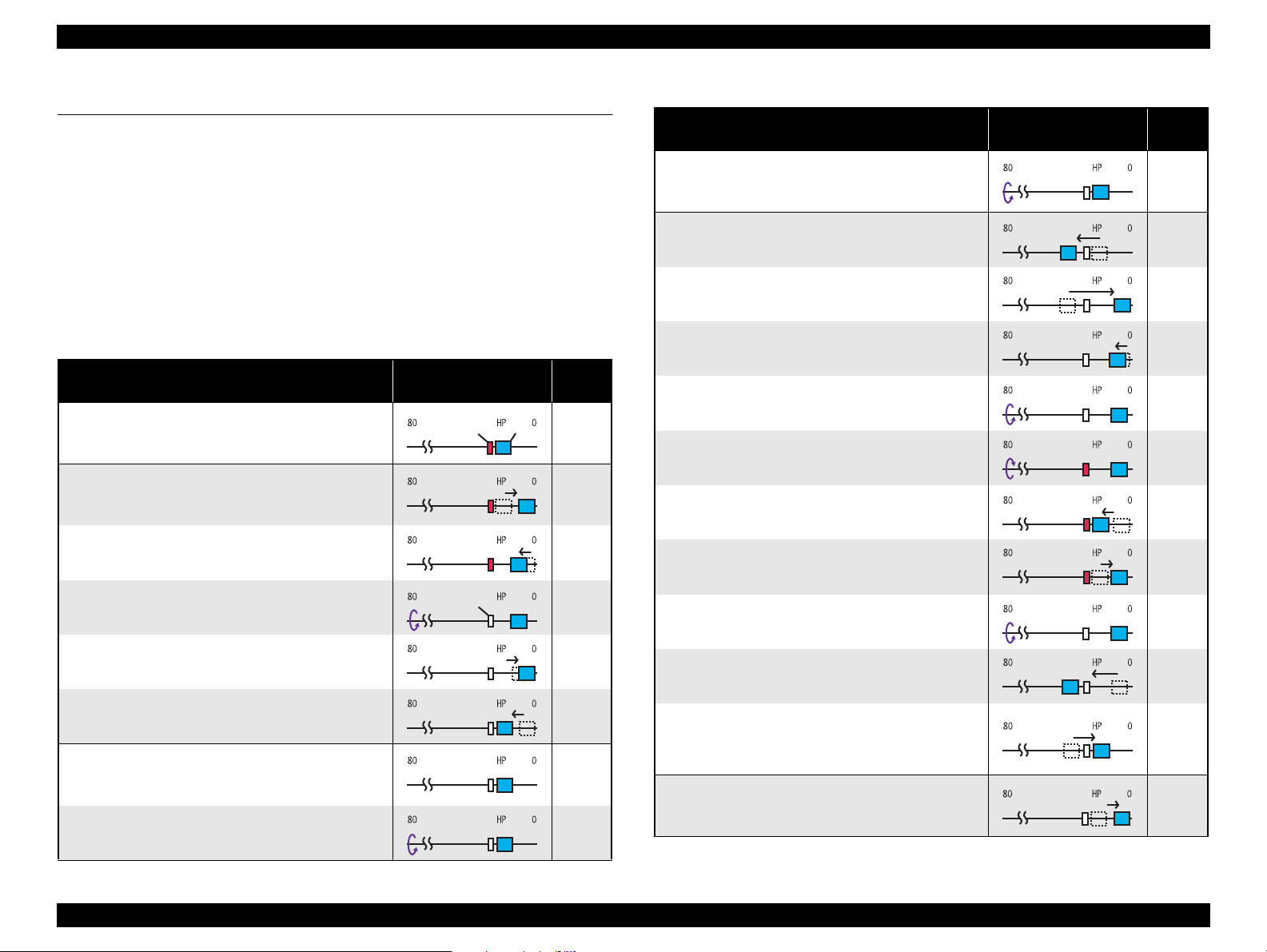
2.3 Power-On Sequence
This section describes the power-on sequences.
Condition
Completing ink charge.
No CDR Tray and no paper on the paper path.
The stacker is not set on the CDR printing position.
The Printhead is capped with the Cap of the Ink System.
The Carriage is locked by the CR lock.
Table 2-5. Operation of the power-on sequence
Operation
1. Checking waste ink overflow
1-1.Reads out the protection counter value to check
waste ink overflow
2. Avoiding deadlock sequence
2-1.The carriage moves to the 0-digit side slowly and
confirms it touches the Right Frame.
2-2.The carriage slightly moves to the 80-digit side.
2-3.The PF Motor rotates clockwise and releases the
CR lock.
2-4.The carriage moves to the 0-digit side slowly and
confirms it touches the Right Frame.
2-5.The carriage returns to its home position.
3. CDR Tray sensor
3-1.Checks with the CDR Tray sensor if the CDR
Tray is not set.
3-2.The PF Motor rotates clockwise to eject the CDR
Tray.
*1
movement and position
*4
Carriage/PF roller
*2
*3
PG
Any
position
↓
↓
↓
↓
↓
↓
↓
Table 2-5. Operation of the power-on sequence
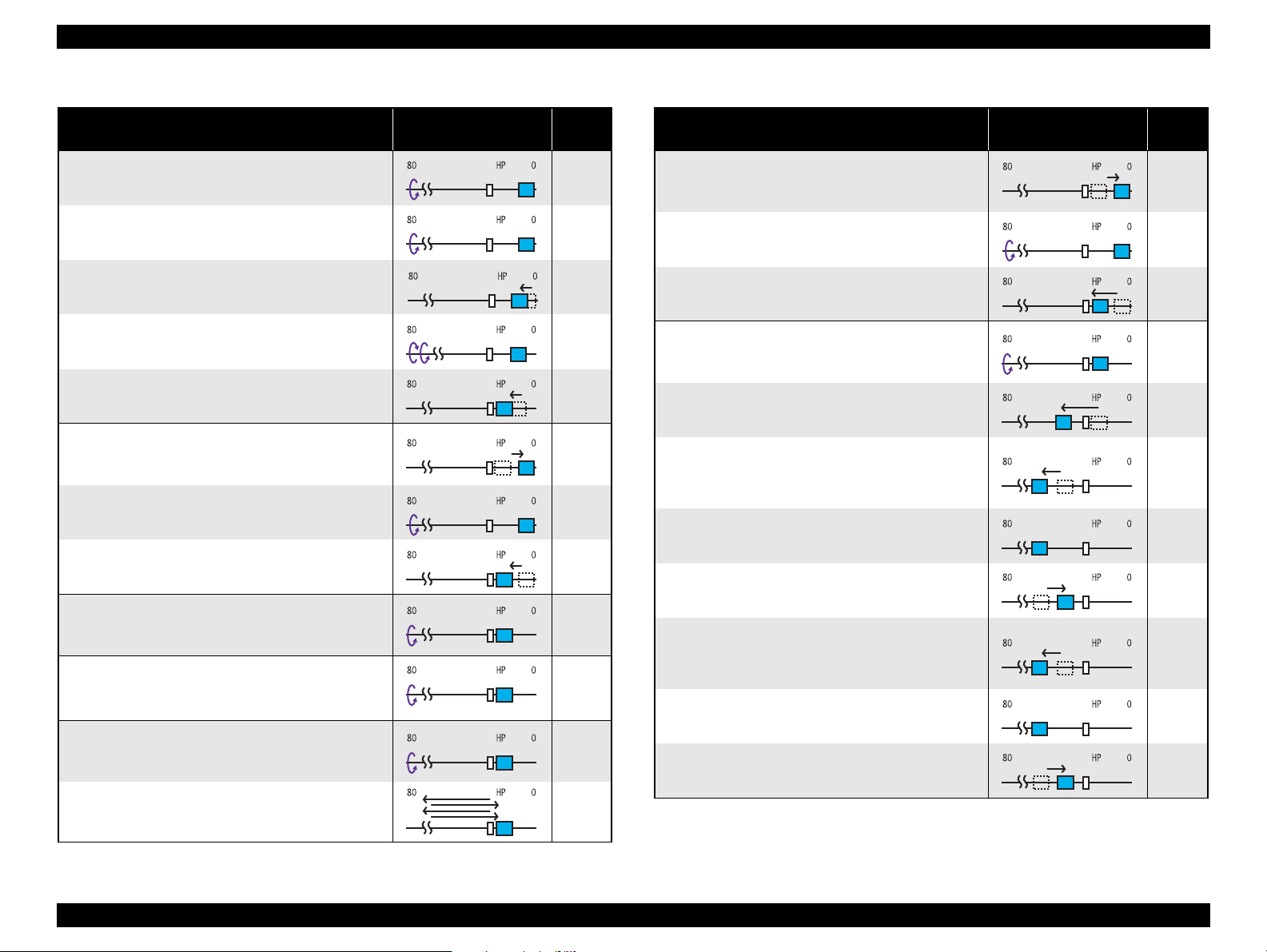
Operation
4. Releasing the CR lock
4-1.The PF Motor rotates clockwise and releases the
CR lock.
5. Seeking the home position
5-1.The carriage slowly moves to the 80-digit side.
5-2.The carriage moves to the 0-digit side slowly and
confirms it touches the Right Frame.
5-3.The carriage slowly moves to the CR lock set
position.
5-4.The PF motor rotates clockwise and releases the
CR lock.
5-5.The PF motor rotates counterclockwise and sets
the CR lock.
5-6.The carriage moves to the 80-digit side slowly and
confirms it touches the CR lock.
5-7.The carriage slowly moves to the 0-digit side to
the CR lock set position.
5-8.The PF motor rotates clockwise and releases the
CR lock.
5-9.The carriage moves to the 80-digit side slowly and
confirms it does not touch the CR lock.
5-10.The carriage slowly moves to its original
position, and home position is fixed.
Afterward, the carriage position is monitored
according to the signals from the CR Encoder.
6. Resetting APG
6-1.The carriage slowly moves to the Right Frame and
stops there.
*1
Carriage/PF roller
movement and position
(Continue to the next page)
*2
*3
PG
Any
position
↓
↓
↓
↓
↓
↓
↓
↓
↓
↓
↓
Chapter 2 Operating Principles 2.3 Power-On Sequence 26
Confidential
Epson Stylus Photo R280/R285/R290/Epson Artisan 50/Epson Stylus Photo T50/T59/T60/P50 Revision C
Table 2-5. Operation of the power-on sequence
Operation
6-2.The PF Motor rotates clockwise while monitoring
the PG sensor.
6-3.After the PG sensor switched from Off to On, the
PF Motor rotates clockwise by the specified step
until it detects the PG— (APG home position).
6-4. After detecting the APG home position, the carriage
slightly moves to
the 80-digit side.
6-5. After the PF Motor rotates counterclockwise
specified step
, it rotates clockwise to confirm the PG
sensor is set to On-state.
6-6.The carriage slowly returns to its home position.
7. Setting the APG to PG++
7-1.The carriage slowly moves to the Right Frame and
stops there.
7-2.The PF Motor rotates clockwise and sets to PG++.
7-3.The carriage slowly returns to its home position.
8. PF initialization
8-1.Checks if paper exists by the PE sensor*5 and the
PF Motor rotates clockwise for one second.
9. PF Motor measurement
9-1.The PF motor rotates clockwise for four seconds,
and performs a load measurement.
10.Low temperature operation sequence
10-1.The PF Motor rotates clockwise, and releases the
CR lock.
10-2.The carriage moves back and forth between CR
lock and the 80-digit side for two times.
*1
by the
*6
*7
Carriage/PF roller
movement and position
*2
*3
PG
Any
position
↓
↓
PG—
↓
↓
PG++
↓
↓
↓
↓
↓
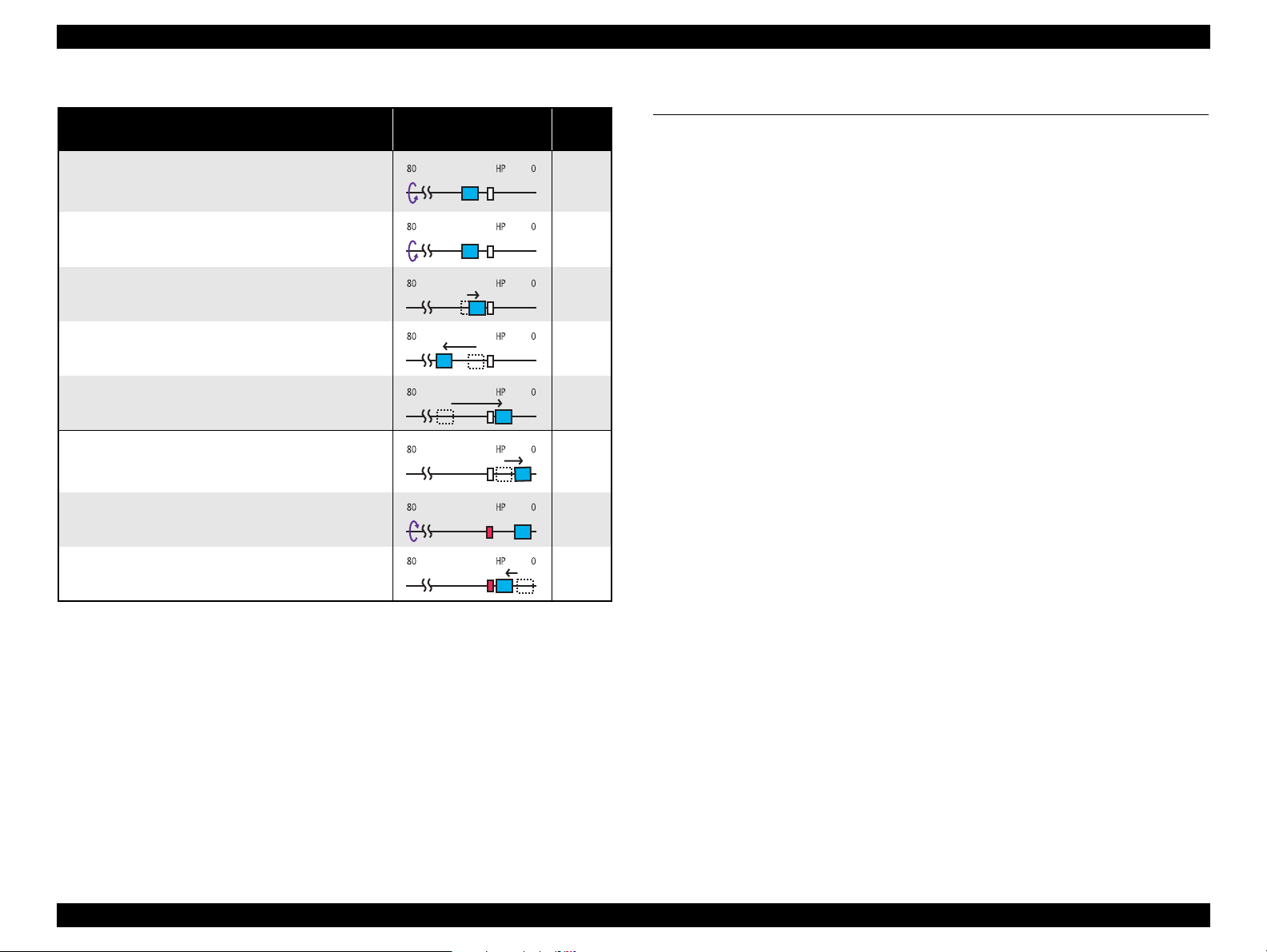
Table 2-5. Operation of the power-on sequence
Operation
11.Setting the APG to PG—
11-1.The carriage slowly moves to the Right Frame
and stops there.
11-2.The PF Motor rotates clockwise and sets to PG—.
11-3.The carriage slowly returns to its home position.
12.CR measurement and PW sensor initialization
12-1.The PF Motor rotates clockwise, and releases the
CR lock.
12-2.The carriage slowly moves to the 80-digit side.
12-3.The carriage performs a load measurement while
moving to the VHCheck position, and records the
detected voltage of the PW sensor at the specified
three positions, then stops.
12-4.The carriage detects the voltage of the PW sensor
at the carriage stop position (the black area at the
Paper Guide Front).
12-5.The carriage performs a load measurement while
moving to the 0-digit side, and stops.
12-6.The carriage performs a load measurement while
moving to the VHCheck position, and records the
detected voltage of the PW sensor at the specified
three positions, then stops.
12-7.The carriage detects the voltage of the PW sensor
at the carriage stop position (the black area at the
Paper Guide Front).
12-8.The carriage performs a load measurement while
moving to the 0-digit side, and stops.
*1
Carriage/PF roller
movement and position
(Continue to the next page)
*3
PG
*2
↓
PG—
↓
↓
↓
↓
↓
↓
↓
↓
↓
Chapter 2 Operating Principles 2.3 Power-On Sequence 27
Confidential
Epson Stylus Photo R280/R285/R290/Epson Artisan 50/Epson Stylus Photo T50/T59/T60/P50 Revision C
Table 2-5. Operation of the power-on sequence
Operation
13.Detecting ink cartridge and initializing ink system
13-1.The PF motor rotates clockwise and releases the
CR lock.
13-2.The PF Motor rotates clockwise for one second,
and resets the PF Roller.
13-3.The carriage slowly moves to the 0-digit side.
13-4.After the carriage moves to the 80-digit side and
checks the ink end sensor, detects the ink
remaining.
13-5.The carriage slowly returns to its home position.
14.CR lock setting
14-1.The carriage slowly moves to the CR lock set
position.
14-2.The PF Motor rotates counterclockwise, and sets
the CR lock.
14-3.The carriage slowly returns to its home position.
Note *1: The rotation direction of the PF Motor is as follows.
Clockwise: Paper is fed normally
Counterclockwise: Paper is fed backward
*2: The condition of the CR lock is as follows.
Red: CR lock is set
White: CR lock is released
*3: Indicates the PG position. “Any position” means that the PG position is not
recognized because APG is not reset yet.
*4: Checks if the carriage is not deadlock such as the CR lock is caught in the gap of the carriage.
*5: Eject the paper if any.
*6: When paper exists, the existing measurement value saved in EEPROM is read out;
therefore, the PF Motor does not rotate.
*7: Executes when the detected temperature is under 5 oC (41oF) by the thermistor on the Printhead.
*8: The empty sanction operation may occur depending on the situation.
*9: If paper remains in the printer, the PF Roller rotates by steps enough to eject the paper forcibly.
*1
*9
Carriage/PF roller
movement and position
*8
2.4 Printer Initialization
*3
PG
*2
↓
↓
PG—
↓
↓
↓
↓
↓
There are four kinds of initialization method, and the following explains each
initialization
1. Hardware initialization
This printer is initialized when turning the printer power on, or printer recognized
the cold-reset command (remote RS command).
When printer is initialized, the following actions are performed.
(a) Initializes printer mechanism
(b) Clears input data buffer
(c) Clears print buffer
(d) Sets default values
2. Operator initialization
Initialization when resetting the USB software, and the following are performed.
(a) Clears input data buffer
(b) Clears print buffer
(c) Sets default values
3. Software initialization
The ESC@ command also initialize the printer.
When printer is initialized, the following actions are performed.
(a) Clears print buffer
(b) Sets default values
4. IEEE 1284.4 “rs” command initialization
The printer recognized the IEEE 1284.4 “rs” command.
When printer is initialized, the following action is performed.
Initialization when an error occurs.
(a) Initializes printer mechanism
(b) Clears input data buffer
(c) Clears print buffer
(d) Sets default values
Initialization in normal operation
(a) Clears input data buffer
(b) Clears print buffer
(c) Sets default values
Chapter 2 Operating Principles 2.4 Printer Initialization 28
Confidential

TROUBLESHOOTING
CHAPTER
3
Confidential
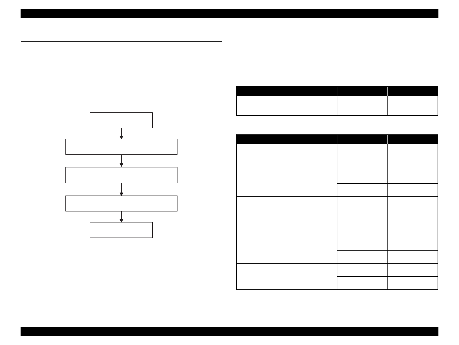
Epson Stylus Photo R280/R285/R290/Epson Artisan 50/Epson Stylus Photo T50/T59/T60/P50 Revision C
Start
Identifying the error cause by the error
message or observed symptom.
Repair or replacement of
parts or components
Reassembly and adjustment
End
3.1 Overview
This chapter provides how to troubleshoot problems analyzing the cause based on the
messages shown by the printer driver, printer’s LED status and the observed symptom.
Identify and troubleshoot the problem referring to the tables on the following pages.
When some parts need to be replaced, make sure to follow the procedure given in
Chapter 4 and carry out required adjustments. If any abnormality is observed in motors
or sensors, check the electrical value referring to the 3.1.1 “Troubleshooting on Motors
and Sensors”(p.30).
3.1.1 Troubleshooting on Motors and Sensors
The following tables show the normal electric values of each motor and sensor. When
any abnormality is observed in motors and sensors, check their electric values and
compare them with the values given in the tables to see if the motors or sensors are
broken or not.
Table 3-1. Motor Resistance & Measuring Points
Motor Motor Connector Measuring Points Resistance
CR Motor
PF Motor
Sensor Sensor Connector Signal Level Status
PE Sensor
APG Sensor
CDR Guide Sensor
CN14 Between Pin 1 and 2 22.7Ω ± 10%
CN13 Between Pin 1 and 2 21.2Ω ± 10%
Table 3-2. Sensor Checkpoints
CN6
Between Pin 1 and 2
CN7
Between Pin 1 and 2
CN4
Between Pin 1 and 2
2.4V or more No paper
0.4V or less Paper exists
2.4V or more Within PG position
0.4V or less Out of PG position
CDR mode
Open: 2.4V or more
Close: 0.4V or less
(Stacker is at the upper
position)
ASF mode
(Stacker is at the lower
position)
Figure 3-1. Troubleshooting Flowchart
CD-R Tray Sensor
Cover OPEN Sensor
Note : See 2.1.2 “ Motors & Sensors ”(p.24) for locations of the motors and sensors.
CN4
Between Pin 3 and 4
CN17
Between Pin 1 and 2
Open: 2.4V or more CD-R Tray inserted
Close: 0.4V or less No CD-R Tray
Open: 2.4V or more Printer Cover opened
Close: 0.4V or less Printer Cover closed
Chapter 3 Troubleshooting 3.1 Overview 30
Confidential
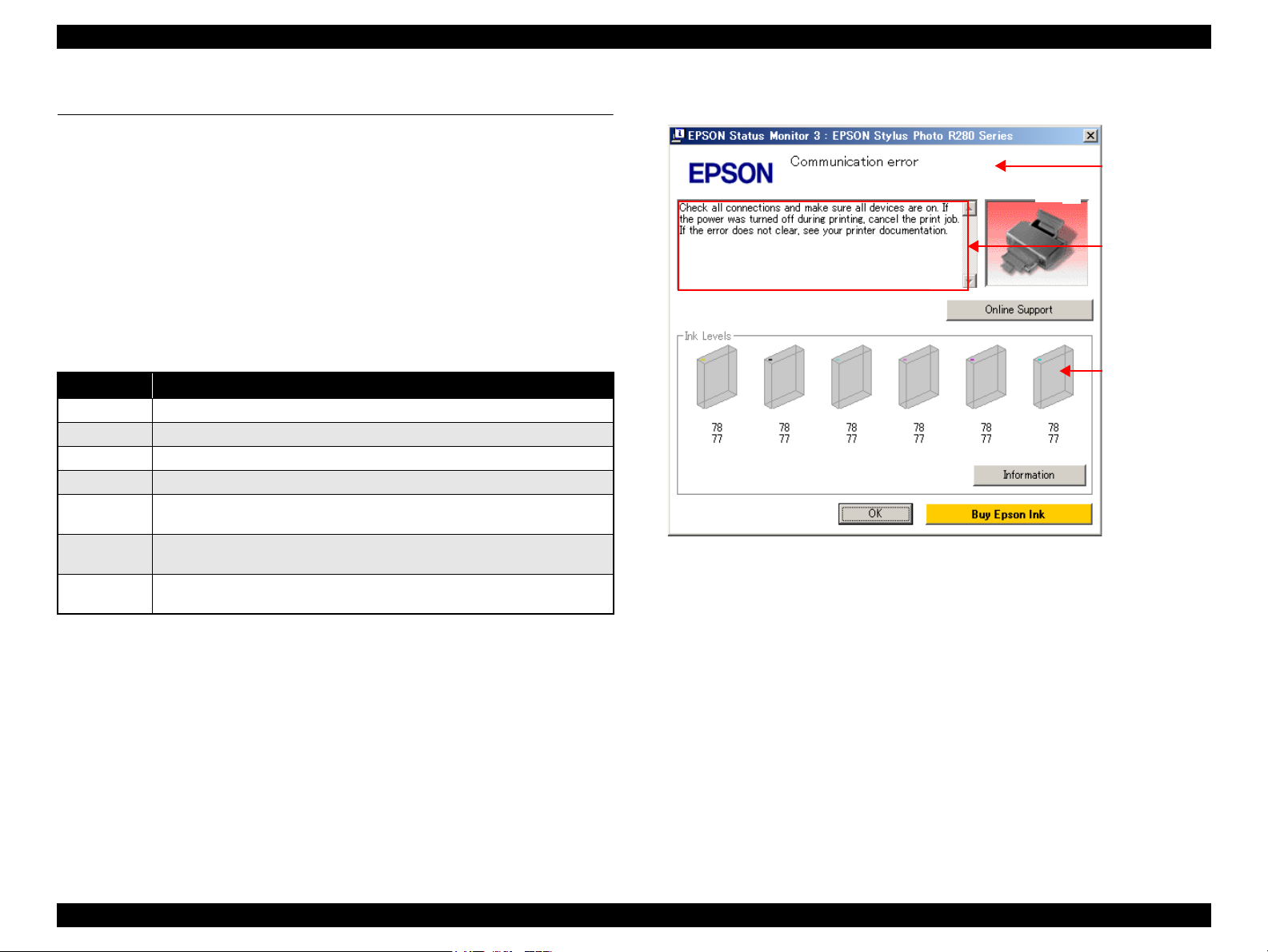
Epson Stylus Photo R280/R285/R290/Epson Artisan 50/Epson Stylus Photo T50/T59/T60/P50 Revision C
Error Message
Ink Level
Descriptions
of the error
3.2 Warning / Error Indications
This section describes how the printer indicates an error/warning status with LEDs, or
on the screen of the printer driver when a problem arises during various operations;
power-on sequence, paper feeding, ink drawing, printing, and so on.
3.2.1 Error Indication Method
The Epson Stylus Photo R280/R285/R290 and Epson Artisan 50/Epson Stylus Photo
T50/T59/T60/P50 are equipped with LEDs. You can check most of the troubles with
the status of the LEDs or messages shown on the windows of “EPSON Status Monitor
3”. (See 1.5.3 “Operation Buttons & LEDs Functions ”(p.19))
LEDs Status
LED Status Meaning
— No change
Light Lights up normally
Flash Flashes at intervals of 1.25 seconds.
Flash 2 Flashes as follows; ON (0.5 sec.) — OFF (0.5 sec.) — ON (0.5 sec.) — OFF (1.0 sec.)
Flashes at high
speed
Flashes
Alternatively 1
Flashes
Alternatively 2
Flashes at intervals of 0.5 seconds.
Same as Flash
Flashes at intervals of 1.25 seconds.
Message box on the window of “EPSON Status Monitor 3”
Figure 3-2. Error Indication on EPSON Status Monitor 3
NOTE: The part number of the Ink Cartridges shown in the Status Monitor 3
screen differs by destination.
Chapter 3 Troubleshooting 3.2 Warning / Error Indications 31
Confidential

Epson Stylus Photo R280/R285/R290/Epson Artisan 50/Epson Stylus Photo T50/T59/T60/P50 Revision C
Table 3-3. List of Error Messages
Error Name
Communication error
Fatal error
Maintenance request
error
CDR Guide error
Paper (CDR) jam
No paper
Multi-feed
CDR Tray error
Ink-out
No ink cartridge
Wrong ink cartridge
Cover open error
Note *: The “XXXX” represents the part number of the Ink Cartridge.
Power Ink Paper
LED Indications
Check all connections and make sure all devices are on. If the
—
Off
Off
—
—Flash
— — Light
— — Light
— — Light Reload the tray, then press the Paper button on the printer. A CD-R tray was not detected.
— Light — Black: XXXX
— Light —
— Light —
— Flash 2 Flash 2
Flashes at
high speed
Flashes
alternately 2
Flashes at
high speed
Flashes at
high speed
Flashes
alternately 1
Flash 2
power was turned off during printing, cancel the print job. If
the error does not clear, see your printer documentation.
Delete all print jobs and turn the printer off. Remove any
foreign objects from inside the printer. After a few minutes,
turn the printer back on.
Parts inside your printer are at the end of their service life. See
your printer documentation.
For sheets of paper, manually set the front tray in the lower
paper position. For a CD or DVD, manually set the front tray
in the upper CD/DVD position.
For sheets of paper, turn off the printer and then remove any
jammed paper by hand. For a CD or DVD, remove the CDR
tray. Next, press the Paper button on the printer or click the
Eject button if it appears on this screen.
Reload the paper and manually set the front tray in the lower
paper position. Then press the Paper button on the printer or
click the Continue button if it appears on the screen.
To cancel all print jobs, click the Cancel button.
A page has not been printed, multiple pages have been fed
into the printer at once, or the wrong paper size has been fed
into the printer. Remove and reload the paper. Press the Paper
button if necessary.
Color: XXXX*
Epson recommends the genuine Epson cartridges listed
above. Click the How to button for ink cartridge replacement
instructions.
Close the printer cover.
*
……………….
STM3 Message Error Cause
The printer cannot communicate with the PC
properly.
A mechanical error has occurred. Table 3-5 (p.34)
Waste ink pads need to be replaced.
• The CD-R guide (stacker) position does not
match with the print job.
• The CD-R guide (stacker) is in the CD-R
printing position at power-ON.
A paper jam has occurred.
Failed to feed paper.
Multiple sheets of paper were fed at the same
time.
The cartridge has run out of ink.
Ink cartridge(s) was not detected.
The Cover Open Sensor detects the Printer Cover
is open.
See the table for
Troubleshooting
Table 3-4 (p.33)
—
Table 3-11 (p.43)
Table 3-8 (p.38)
Table 3-9 (p.40)
Table 3-8 (p.38)
Table 3-10 (p.42)
Table 3-7 (p.37)
Table 3-6 (p.36)
Chapter 3 Troubleshooting 3.2 Warning / Error Indications 32
Confidential

Epson Stylus Photo R280/R285/R290/Epson Artisan 50/Epson Stylus Photo T50/T59/T60/P50 Revision C
3.3 Troubleshooting by Error Message
The following tables provide troubleshooting procedure for each error indicated by the LEDs or STM3 screen. When some parts need to be replaced or repaired, make sure to follow
the procedure given in Chapter 4 and carry out required adjustments.
3.3.1 Troubleshooting Problems with Error Messages
Table 3-4. Troubleshooting for Communication Error
Occurrence
Timing
At power-on
Symptom Failed Part Check Point Remedy Reference
The printer does not
work at all.
Panel Board/
Panel FFC
P/S ASSY
USB cable
Printer driver
1. Is the Panel FFC not connected to the Panel Board
and CN5 on the Main Board?
2. Is the Panel FFC damaged? 2. Replace the Panel FFC.
3. Is the Panel Board damaged? 3. Replace the Panel Board.
1. Is the P/S ASSY connector cable not connected to
CN3 on the Main Board?
2. Is the P/S ASSY cable or the P/S ASSY itself
damaged?
1. Is the USB cable not connected to the printer and
the PC?
1. The printer driver installed on the PC is not the
one for the Epson Stylus Photo R280/R285/R290
and Epson Artisan 50/Epson Stylus Photo T50/
T59/T60/P50?
1. Connect the FFC correctly.
1. Connect the cable correctly.
2. Replace the P/S ASSY.
* If this does not solve the problem, replace the
Main Board Assy.
1. Connect the USB cable correctly.
1. Install the correct printer driver.
4.3.2 “Panel Assy/
Cover Open
Sensor”(p.67)
4.3.3 “P/S Assy”(p.71)
—
—
Main Board
1. The model name written into EEPROM on the
Main Board is wrong?
1. Write the correct model name to the EEPROM
using the Adjustment Program.
5.1.1 «Servicing
Adjustment Item List»
(P.104)
Chapter 3 Troubleshooting 3.3 Troubleshooting by Error Message 33
Confidential
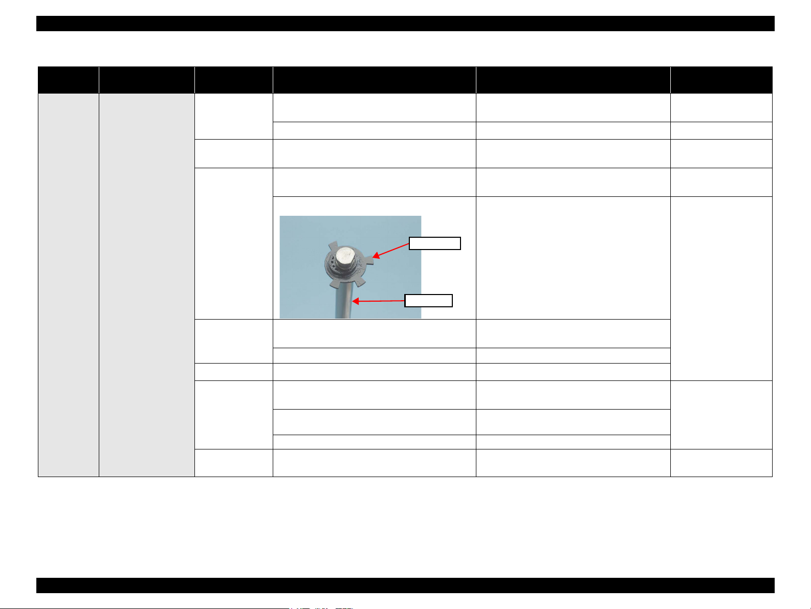
Epson Stylus Photo R280/R285/R290/Epson Artisan 50/Epson Stylus Photo T50/T59/T60/P50 Revision C
Table 3-5. Troubleshooting for Fatal Error
Occurrence
Timing
Symptom Failed Part Check Point Remedy Reference
At power-on
• CR motor does not
rotate at all.
• CR Unit hits against
the right side of the
Main Frame.
CR Motor
Main Frame
CR Guide Shaft
CR Encoder
Head FFC
CR Scale
Timing Belt
1. Is the CR motor cable not connected to CN14 on
the Main Board?
2. Is there a malfunction of the CR motor?
1. Is their any dirt on the Main Frame? Or is the
frame not adequately lubricated?
1. Is their any dirt on the CR Guide Shaft? Or is the
shaft not adequately lubricated?
2. Is the PG cam chipped or broken? 2. Replace the CR Guide Shaft.
1. Is the Head FFC not connected to the CR encoder
connector?
2. Is the CR encoder chipped or broken?
1. Is the Head FFC broken? 1. Replace the Head FFC.
1. Is the CR Scale not moving freely, centered
between the sides of CR encoder sensor?
2. Is there any dirt on the CR Scale? 2. Clean off any dirt on the CR Scale. If the scale
3. Is the CR Scale chipped or broken? 3. Replace the CR Scale.
1. Is the Timing Belt attached incorrectly?
1. Connect the cable correctly.
2. Replace the CR motor.
1. Clean off any dirt on the frame and apply
adequate grease on it.
1. Clean off any dirt on the shaft and apply
adequate grease on it.
1. Connect the Head FFC to the connector
correctly.
2. Replace the CR Unit.
1. Install the CR Scale correctly.
get heavily soiled, replace the scale.
1. Attach the belt correctly.
4.3.1 “Main Board
Unit”(p.64)
4.4.12 “CR Motor”(p.87)
6.1.3 «Lubrication»
(P.122)
6.1.3 «Lubrication»
(P.122)
4.4.13 “CR Unit”(p.89)
4.4.3 “CR Scale”(p.77)
4.4.13 “CR Unit”(p.89) /
4.4.12 “CR Motor”(p.87)
Chapter 3 Troubleshooting 3.3 Troubleshooting by Error Message 34
Confidential
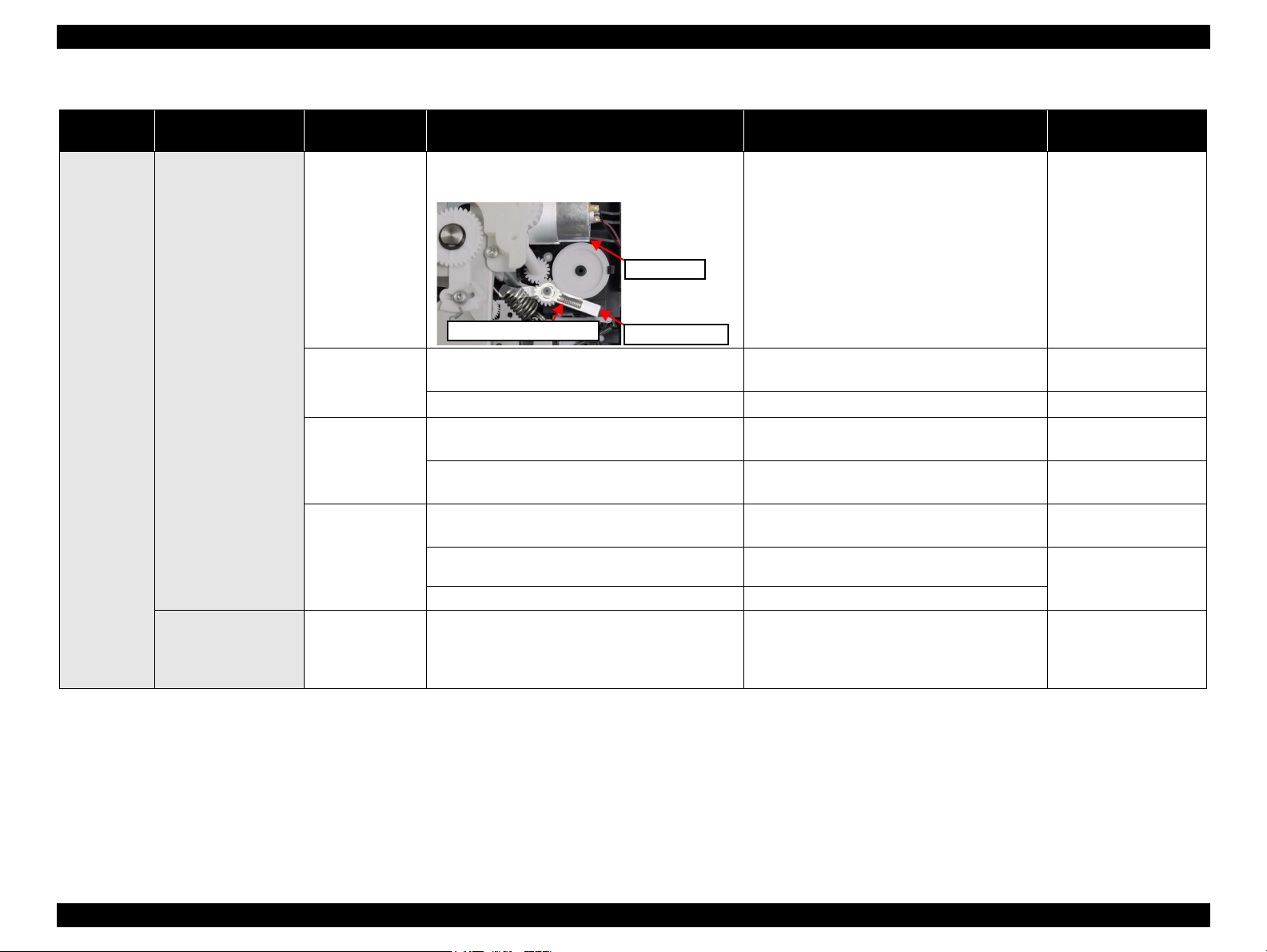
Epson Stylus Photo R280/R285/R290/Epson Artisan 50/Epson Stylus Photo T50/T59/T60/P50 Revision C
Compression Spring2.36
Change Lever
CR Motor
Table 3-5. Troubleshooting for Fatal Error
Occurrence
Timing
Symptom Failed Part Check Point Remedy Reference
1. Is the Compression spring 2.36 of the Change
Lever disengaged?
1. Replace the ASF Unit.
At power-on
• The CR Unit hits
against the Change
Lever which has come
down toward the front
of the printer.
• The error appears after
the PF roller makes
quick one-turn.
The CR Unit hits
against the Upper Paper
Guide detached from
the Main Frame.
ASF Unit
PF Motor
PF Encoder
PF Scale
Upper Paper Guide
1. Is the PF motor cable not connected to CN13 on
the Main Board?
2. Is there a malfunction of the PF motor? 2. Replace the PF motor.
1. Is the PF encoder FFC not connected to the PF
encoder connector and the Main Board?
2. Is the PF encoder chipped or broken? 2. Replace the PF encoder.
1. Is the PF Scale not moving freely, centered
between the sides of PF encoder sensor?
2. Is their any dirt on the PF Scale? 2. Clean off any dirt on the PF Scale. If the scale
3. Is the PF Scale chipped or broken? 3. Replace the PF Scale.
1. Is the Upper Paper Guide detached from the Main
Frame?
1. Connect the cable to the Main Board.
1. Connect the FFC to the PF encoder and the
Main Board.
1. Install the PF Scale or PF encoder correctly.
gets heavily soiled, replace the scale.
1. Attach the Upper Paper Guide correctly.
4.4.14 “ASF Unit”(p.92)
4.3.1 “Main Board
Unit”(p.64)
4.4.11 “PF Motor”(p.87)
4.3.1 “Main Board
Unit”(p.64)
4.4.10 “PF Encoder / PF
Scale”(p.86)
4.4.10 “PF Encoder / PF
Scale”(p.86)
4.4.10 “PF Encoder / PF
Scale”(p.86)
4.4.15 “Upper Paper
Guide”(p.94)
Chapter 3 Troubleshooting 3.3 Troubleshooting by Error Message 35
Confidential
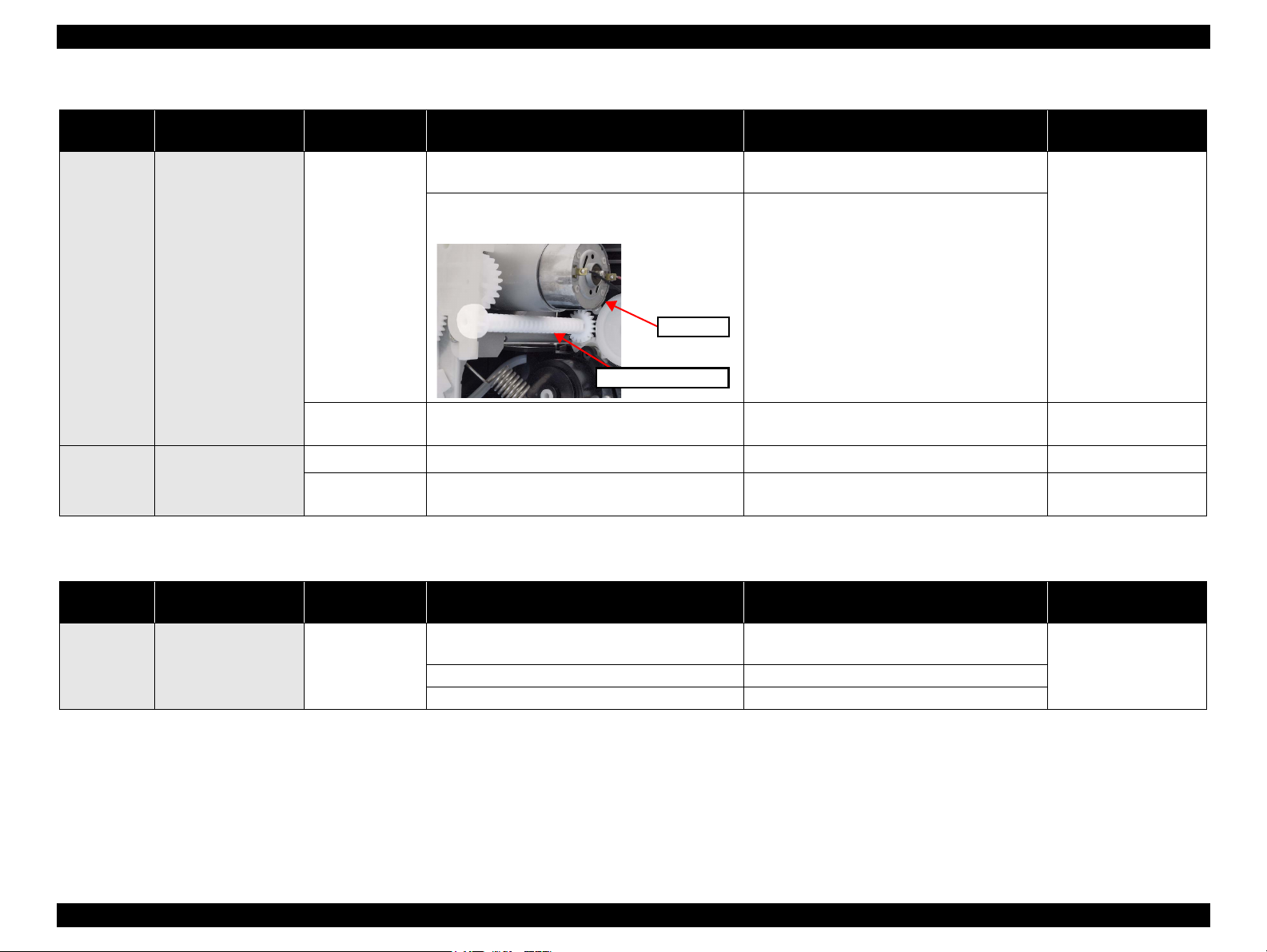
Epson Stylus Photo R280/R285/R290/Epson Artisan 50/Epson Stylus Photo T50/T59/T60/P50 Revision C
Combination Gear
CR Motor
Table 3-5. Troubleshooting for Fatal Error
Occurrence
Timing
At power-on
During
changing the
platen gap
Symptom Failed Part Check Point Remedy Reference
1. Is the APG Unit installed incorrectly? 1. Install the APG Unit carefully so as not to shift
the phase.
The error occurs when
the PG (gap between
the printhead surface
and the platen) is
changed with the APG
Unit.
2. Is the Combination Gear 10,15.2 disengaged or
attached incorrectly?
APG Unit
2. Attach the gear correctly.
4.4.4 “APG Unit”(p.78)
Any time
Occurrence
Timing
At power-on
Other than above
symptoms
APG Sensor Assy
Printhead
Main Board
1. Is the APG sensor damaged?
1. Is the Printhead damaged?
1. Is the Main Board damaged? 1. Replace the Main Board.
1. Replace the APG Sensor Assy.
1. Replace the Printhead.
4.4.16 “APG Sensor
Assy”(p.95)
4.4.2 “Printhead”(p.75)
4.3.1 “Main Board
Unit”(p.64)
Table 3-6. Troubleshooting for Cover Open Error
Symptom Failed Part Check Point Remedy Reference
The Printer Cover is
closed, but the Cover
Open error occurs.
Cover Open Sensor
1. Is the Cover Open Sensor cable not connected to
CN17 on the Main Board?
2. Is the
3. Is the Cover Open Sensor
Cover Open Sensor cable
damaged
damaged?
? 3. Replace the Cover Open Sensor.
1. Connect the cable to the connector on the Main
Board.
2. Replace the Cover Open Sensor cable.
4.3.2 “Panel Assy/ Cover
Open Sensor”(p.67)
Chapter 3 Troubleshooting 3.3 Troubleshooting by Error Message 36
Confidential
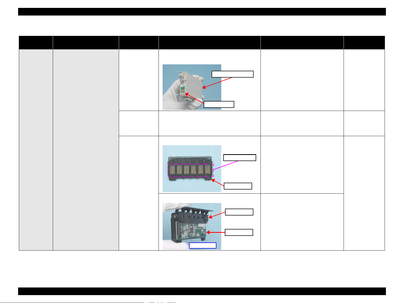
Epson Stylus Photo R280/R285/R290/Epson Artisan 50/Epson Stylus Photo T50/T59/T60/P50 Revision C
Memory Chip
Ink Cartridge
Table 3-7. Troubleshooting for Ink Cartridge Detection Error/ Ink Cover Open Error/ Cartridge Empty Error
Occurrence
Timing
Symptom Failed Part Check Point Remedy Reference
1. Is the memory chip on the cartridge chipped or
broken?
1. Replace the ink cartridge.
At power-on
The error appears after the
carriage home position is
detected.
Ink Cartridge
Head FFC
Head Board
1. Is the Head FFC not connected to the Head Board
and CN10, CN11, and CN12 on the Main Board?
1. Are the CSIC terminals chipped or broken? 1. Replace the CSIC ASSY.
2. Is the Head Board damaged? 2. Replace the CSIC ASSY.
1. Connect the Head FFC to the Head
Board and the Main Board.
—
4.4.13 “CR
Unit”(p.89) / 4.3.1
“Main Board
Unit”(p.64)
4.4.2
“Printhead”(p.75)
Chapter 3 Troubleshooting 3.3 Troubleshooting by Error Message 37
Confidential
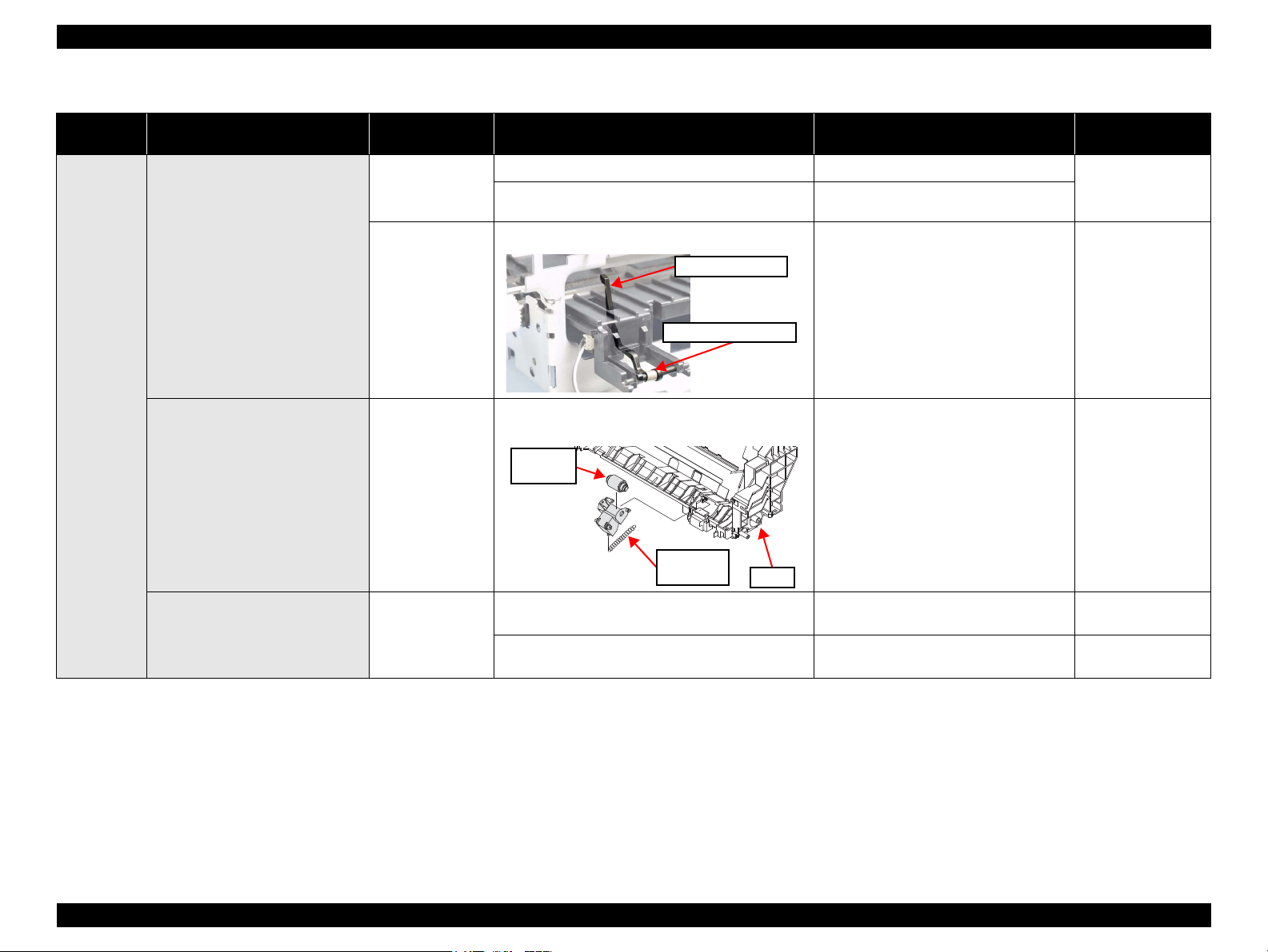
Epson Stylus Photo R280/R285/R290/Epson Artisan 50/Epson Stylus Photo T50/T59/T60/P50 Revision C
Torsion Spring 0.22
PE Sensor Lever
Extension
Spring
ASF
Retard
Roller
Table 3-8. Troubleshooting for Paper Jam Error
Occurrence
Timing
Even though the printer performs
paper feeding operation, the paper is
not fed into the printer.
Symptom Failed Part Check Point Remedy Reference
ASF Unit
Front Paper Guide
Assy
1. Is the ASF Unit installed incorrectly?
2. Is the Paper Return Lever not moving properly
during the feeding operation?
1. Is the Torsion Spring 0.22 attached incorrectly? 1. Install the PE Sensor Lever and Torsion
1. Install the ASF Unit correctly.
2. Install the Paper Return Lever and the
Torsion Spring 6.45 correctly.
Spring 0.22 correctly.
4.4.14 “ASF
Unit”(p.92)
4.4.17 “Front Paper
Guide Assy”(p.96)
Any time
Multiple sheets are fed at a time.
Paper is fed into the printer, but
ejected at once without any printing
operation.
ASF Unit
PE Sensor
1. Is the Retard Roller Assy not moving properly
during the feeding operation?
1. Is the PE sensor cable not connected to CN6 on
the Main Board?
1. Is the PE Sensor damaged? 2. Replace the PE Sensor.
1. Attach the Extension Spring 1.98 on the
back side of the Retard Roller Assy
correctly.
1. Connect the cable to the Main Board.
4.4.14 “ASF
Unit”(p.92)
4.3.1 “Main Board
Unit”(p.64)
4.4.17 “Front Paper
Guide Assy”(p.96)
Chapter 3 Troubleshooting 3.3 Troubleshooting by Error Message 38
Confidential
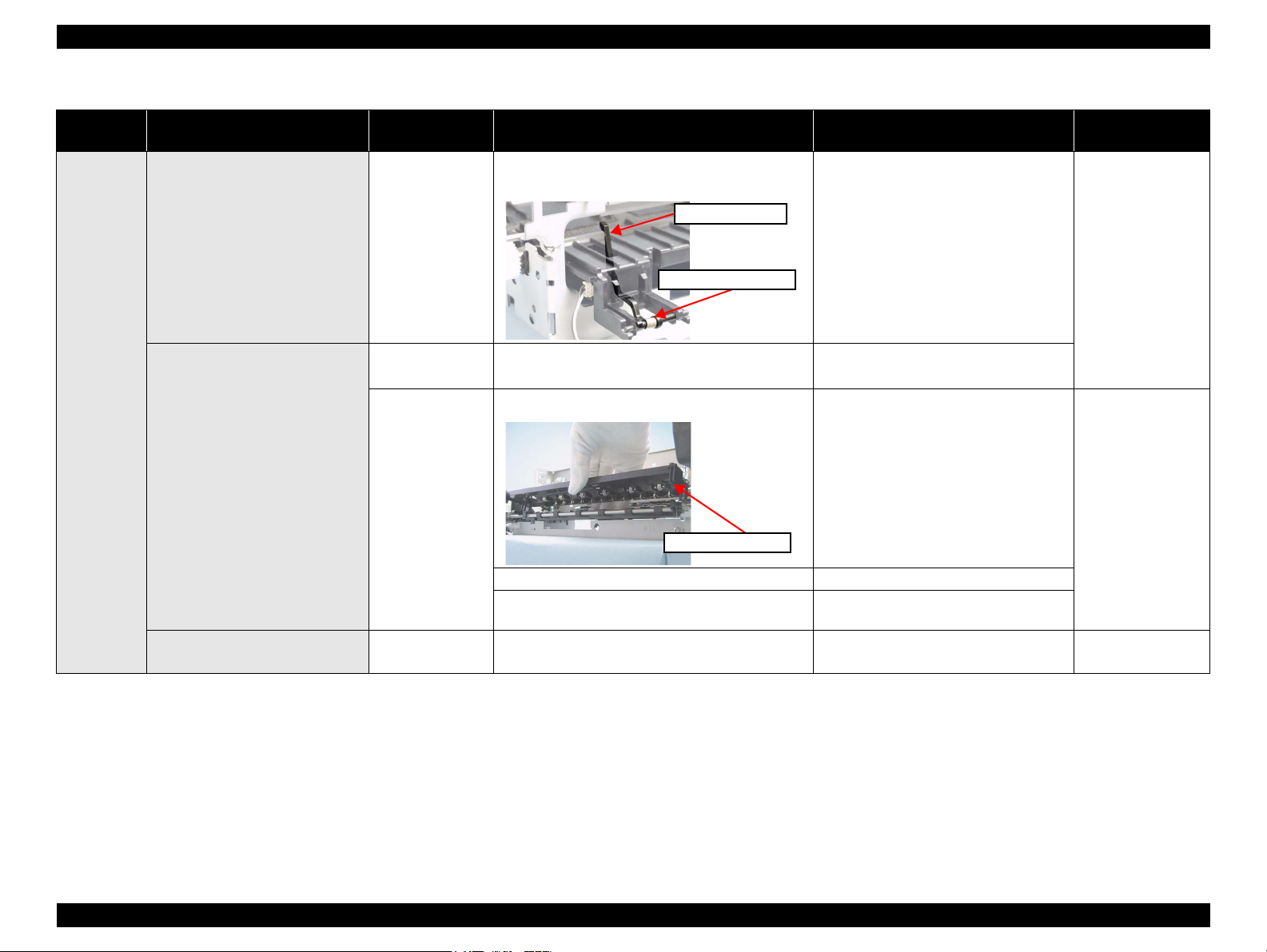
Epson Stylus Photo R280/R285/R290/Epson Artisan 50/Epson Stylus Photo T50/T59/T60/P50 Revision C
Torsion Spring 0.22
PE Sensor Lever
Table 3-8. Troubleshooting for Paper Jam Error
Occurrence
Timing
Paper is fed into the printer, but
ejected at once without any printing
operation.
Symptom Failed Part Check Point Remedy Reference
3. Is the Torsion Spring 0.22 detached or attached
incorrectly?
PE Sensor
3. Install the PE Sensor Lever and the
Torsion Spring 0.22 correctly.
4.4.17 “Front Paper
Guide Assy”(p.96)
Front Paper Guide
Pad
Any time
Paper cannot go through between
the EJ Roller and the Star Wheel
Roller.
The leading edge of paper does not
reach the PF Roller.
Note : * Be careful not to let jammed paper rub against the nozzle surface of the Printhead, or it may damage the Printhead.
EJ Frame ASSY*
Upper Paper Guide*
1. Is the Front Paper Guide Pad attached incorrectly?
1. Is the Star Wheel Holder detached?
2. Is the EJ Frame Assy installed incorrectly? 2. Install the EJ Frame Assy correctly.
3. Has the EJ Frame Assy become deformed
obstructing the paper path?
1. Is the Upper Paper Guide disengaged from the
Main Frame?
1. Install the pad correctly.
1. Attach the Star Wheel Holder correctly.
3. Replace the EJ Frame Assy.
1. Install the Upper Paper Guide correctly.
4.4.9 “EJ Frame
Assy”(p.84)
4.4.15 “Upper Paper
Guide”(p.94)
Chapter 3 Troubleshooting 3.3 Troubleshooting by Error Message 39
Confidential
 Loading…
-
Bookmarks
Quick Links
Start Here
Please read these instructions before using the printer.
1
Unpack
CD/DVD adapter
CD/DVD tray
Caution:
Do not open ink cartridge packages until you are ready to install the ink.
Cartridges are vacuum packed to maintain reliability.
If anything is missing, contact Epson as described on the back of this sheet.
Remove all protective materials.
2
Turn on the printer
1
Connect the power cable.
Caution:
Do not connect to your computer yet.
2
Press the
power button.
*411642400*
*411642400*
3
Install ink cartridges
Caution:
Keep ink cartridges out of the reach of children and do not drink the ink.
Note:
The ink cartridges that come with your printer have a lower yield due to the ink
system charging process. This process is carried out the first time you turn on your
printer and guarantees better performance.
Don’t load paper before installing ink cartridges.
1
Lift up the printer cover, then open the cartridge cover.
2
U npack the ink cartridges.
3
Remove only the yellow tape from each cartridge.
Caution:
Don’t remove any other seals from the cartridges.
4
I nsert the cartridges in the holder for each color. Press the cartridges
down until they click.
5
Close the ink cartridge cover and press it down until it clicks. Then close
the printer cover.