-
Contents
-
Table of Contents
-
Bookmarks
Related Manuals for ABB SF6 LTB 245E1 BLG 1002A
Summary of Contents for ABB SF6 LTB 245E1 BLG 1002A
-
Page 1
Product Manual 1HSB435416-2 en Rev 1 LTB 245E1 BLG 1002A 3-pole operation… -
Page 2: Table Of Contents
PRODUCT DESCRIPTION — Circuit-Breaker PRODUCT DESCRIPTION — Operating Mechanism ASSEMBLY INSTRUCTIONS CHECKLIST OPERATING AND MAINTENANCE INSTRUCTIONS LUBRICANTS MAINTENANCE INSTRUCTIONS — Operating Mechanism OVERHAUL INSTRUCTIONS — Circuit-Breaker SPARE PARTS — Circuit-Breaker SPARE PARTS ABB Switchgear AB — Operating Mechanism S-771 80 LUDVIKA…
-
Page 3
Circuit-Breaker LTB 245E1 with operating mechanism BLG 1002A 3-pole operation Product Description 1HSB435455-2 enrev1 ABB Switchgear… -
Page 4
The information in this document is subject to alteration without prior notice and should not be regar- ded as an undertaking from ABB Switchgear AB. ABB Switchgear AB takes no responsibility for errors that can occur in the documentation. ABB Switchgear AB is not responsible for damage incurred due to the misuse of this document. -
Page 5
Product Description LIST OF CONTENTS 1. Description…………….1 Design of the circuit-breaker…………1 The circuit-breaker’s gas system ………… 2 Operating mechanism…………..3 Standards ………………3 1HSB435455-2 enrev1… -
Page 6: Description
Description Product Description 1. Description High voltage circuit-breaker type LTB 245E1with a single operating mechanism type BLG 1002A. 1.1 Design of the circuit-breaker The circuit-breaker is made up of three separate poles. These consist of three main parts. At the bottom is an operating mechanism in an alloy housing, above this are hollow post insulator through which the operating insulator runs and at the top is the breaking unit.
-
Page 7: The Circuit-Breaker’s Gas System
Description Product Description 1.2 The circuit-breaker’s gas system The circuit-breaker poles are permanently filled with SF gas at a pressure of 0.7 MPa abs at 20°C on circuit-breakers whose performance is limited by a lowest ambient temperature of ≥ -30°C. On circuit-breakers whose ambient temperature is ≥…
-
Page 8: Operating Mechanism
Description Product Description 1.3 Operating mechanism LTB circuit-breaker is operated by a motor-charged spring operating mechanism type BLG. The operating mechanism is connected to the poles’ mechanism on the circuit- breaker pole via a pull-rod system. The circuit-breaker is closed by the operating mechanism, which houses the closing springs.
-
Page 9
ABB Switchgear AB 1HSB435455-2 enrev1 Head Office 0008 SE-771 80 LUDVIKA SWEDEN Telephone: +46 (0) 240 782 000 Telefax: +46 (0) 240 714 928… -
Page 10
Circuit-Breaker Operating Mechanism type BLG 1002A Product Description 1HSB515432-100 en rev2 ABB Switchgear… -
Page 11
The information in this document is subject to alteration without prior notice and should not be regar- ded as an undertaking from ABB Switchgear AB. ABB Switchgear AB takes no responsibility for errors that can occur in the document. ABB Switchgear AB is not responsible for damage incurred due to the misuse of this document. -
Page 12
Product Description LIST OF CONTENTS 1. Description…………….1 Normal operating mode …………..2 Opening operation…………….3 Closing operation …………….4 2. Component units …………..5 Drive unit ………………5 Mechanical interlock……………5 Catch gear ………………6 Dashpots………………6 Auxiliary contact…………….7 Heater element …………….8 1HSB515432-100 en rev2… -
Page 13
Product Description FIGURES Figure 1-1. Operating mechanism …………..1 Figure 1-2. Normal operating mode…………..2 Figure 1-3. Opening operation…………….3 Figure 1-4. Closing operation…………….4 Figure 2-1. Drive unit………………5 Figure 2-2. Interlocking mechanism…………..5 Figure 2-3. -
Page 14: Description
Product Description Description 1. Description The spring operating mechanism BLG 1002A is intended for operating a circuit- breaker with integrated opening springs. The opening springs are charged automatically by the mechanism on closing of the circuit-breaker, whereby the requisite energy for opening is obtained. Under no circumstances may the mechanism be operated with the spring battery charged, without first being fitted and trimmed with the associated circuit-breaker.
-
Page 15: Normal Operating Mode
Description Product Description 1.1 Normal operating mode During normal service the circuit-breaker is in the closed position. The opening spring (14) on the circuit-breaker and the closing springs (7) in the operating mechanism are charged. The circuit-breaker is kept in the closed position by the operating mechanism’s opening catch gear (1).
-
Page 16: Opening Operation
Product Description Description 1.2 Opening operation The latch in the opening catch gear (1) is released on opening of the circuit-breaker (1). The opening spring (14) pulls, via the pull-rod (13), the operating lever (4) to the left. The movement is damped by the opening dashpot (3) at the end position before the operating lever (4) rests against the cam disc (5).
-
Page 17: Closing Operation
Description Product Description 1.3 Closing operation On closing of the circuit-breaker, the latch is released in the closing catch gear (2). The chain section (17) is released and transfers the closing spring’s (7) energy to the cam disc (5). The cam disc rotates 360° clockwise and pulls the operating lever (4) to the right until the opening catch gear (1) engages.
-
Page 18: Component Units
Product Description Component units 2. Component units 2.1 Drive unit The drive unit is supplied with one or two motor options for 60, 110 or 220 V DC and 50, 60 Hz AC. The motor should be able to charge the springs at 85% of the nominal voltage (IEC). Item Drive unit B20031…
-
Page 19: Catch Gear
Component units Product Description 2.3 Catch gear The operating mechanism is fitted as standard with one closing coil and two opening coils, but on request can be equipped with double coils on the closing side. The standard voltage of the coil is 110, 220 V DC or AC, but other voltages may occur.
-
Page 20: Auxiliary Contact
Product Description Component units 2.5 Auxiliary contact The operating mechanism is equipped as standard with a 6-pole auxiliary contact consisting of six opening and six closing contacts. Three closing and one opening contact are used for the functioning of the operating mechanism. There is a possibility of supplementing with six or twelve extra contacts.
-
Page 21: Heater Element
Component units Product Description 2.6 Heater element The operating mechanism is equipped with a heater element to prevent condensation from forming and should always be connected. Item Heater element B20036 Figure 2-6. Heater element. 1HSB515432-100 en rev2…
-
Page 22
1HSB515432-100 en rev2 ABB Switchgear AB Head Office 9911 SE-771 80 LUDVIKA SWEDEN Telephone: +46 (0) 240 782 000 Telefax: +46 (0) 240 714 928… -
Page 23
Circuit-Breaker LTB 245E1 with operating mechanism BLG 1002A 3-pole operation Assembly Instructions 1HSB435410-2 enrev1 ABB Switchgear… -
Page 24
The information in this document is subject to alteration without prior notice and should not be regar- ded as an undertaking from ABB Switchgear AB. ABB Switchgear AB takes no responsibility for errors that can occur in the document. ABB Switchgear AB is not responsible for damage incurred due to the misuse of this document. -
Page 25
Assembly Instructions LIST OF CONTENTS 1. General …………….1 2. Safety………………. 3 Warning text ………………. 3 Safety, general …………….4 3. Delivery …………….5 Weights………………. 5 Unpacking ………………6 Storage before assembly …………..7 4. Assembly…………….9 Preparations………………9 Frame assembly…………….11 Assembling the frame on the foundation …….. -
Page 26
Assembly Instructions Times ……………….. 37 Motor and control circuits …………37 Resistance ………………37 Contact stroke…………….37 1HSB435410-2 enrev1… -
Page 27
Assembly Instructions FIGURES Figure 3-1. Component parts…………….5 Figure 3-2. Lifting the operating mechanism …………6 Figure 4-1. Assembly markings……………..9 Figure 4-2. Foundation………………10 Figure 4-3. Frame assembly…………….11 Figure 4-4. Frame assembly on the foundation……….12 Figure 4-5. Lifting the circuit-breaker pole………….13 Figure 4-6. -
Page 28
General Assembly Instructions 1. General This assembly instructions applies to the SF circuit-breaker type LTB 245E1 with one operating mechanism type BLG 1002A for 3-pole operation and contain all essential information for assembly and commissioning Read through the entire Assembly Manual before starting the assembly work. 1HSB435410-2 enrev1… -
Page 29: Safety
Safety Assembly Instructions 2. Safety 2.1 Warning text Warning text occurs where required and indicates that the text in question should be observed extra carefully. The warning texts are marked as set out below: DANGER indicates an immediate hazardous situation that, if not avoided, will result in death or serious injury.
-
Page 30: Safety, General
Safety Assembly Instructions 2.2 Safety, general WARNING Circuit-breaker with pressurised porcelain insulators. Mechanical effects on the porcelain can cause it to explode with the following risk of splintering. Work on the circuit-breaker that brings about the risk of mechanical damage to the insulators should be carried out at a reduced gas pressure, 0.125 MPa (abs).
-
Page 31: Delivery
If any material is missing or if transport damage has occurred, please report this immediately to ABB Switchgear AB, Circuit Breaker Division. 3.1 Weights The weights of the component parts are as follows:…
-
Page 32: Unpacking
Delivery Assembly Instructions 3.2 Unpacking The operating mechanism with blocking beams is packed in a wooden crate or on a pallet. The crate is marked with the case number and the gross weight. Other information is written on a plywood board/label, which is attached to two of the crate’s sides.
-
Page 33: Storage Before Assembly
Delivery Assembly Instructions 3.3 Storage before assembly 3.3.1 General The circuit-breakers are normally delivered in units adapted for transport. Intermediate storage of these units should be avoided. If intermediate storage can not be avoided the units should be stored indoors or under a roof. They should also be stored horizontally above ground level to avoid cracking or water damage.
-
Page 34
Delivery Assembly Instructions 3.3.3 Operating mechanism The operating mechanism should be unpacked on arrival. If it is not kept in an approved store, the heating element must be connected and permanently switched on to prevent the control equipment from corrosion or damage due to freezing. 3.3.4 Circuit-breakers The circuit-breakers should be stored in their original cases where they are properly protected from damage. -
Page 35: Assembly
Lifting devices and lifting slings. • Lubricants, see Lubricants 1HSB445409-1 for suppliers and brand names. Grease “G”: ABB article number1171 4014-407 Grease “SV”: ABB article number 1171 4016-610. • Contact paste. • Applicable dimension drawings and diagrams for the order.
-
Page 36
Assembly Assembly Instructions 4.1.2 Foundation The circuit-breaker’s foundation must be flat and level. Figure 4-2 shows the permitted deviations in mm for the position of the foundation bolts and for the phase spacing. Adjust any deviation using spacer washers, see “Chapter 4.3, Assembling the frame on the foundation”. -
Page 37: Frame Assembly
Assembly Assembly Instructions 4.2 Frame assembly The frame is supplied in welded halves with six cross stays and nuts, bolts and washers. Bolt the halves together as shown in Figure 4-3. Fit the cross stays according to the numbering 1-4, using the supplied nuts, bolts and washers. N.B.
-
Page 38: Assembling The Frame On The Foundation
Assembly Assembly Instructions 4.3 Assembling the frame on the foundation Check that the frames are upright and adjust them to the same level using the nuts (2). Fill with spacer washers the gap between the lower nut and the foundation, which should be as small as possible.
-
Page 39: Assembling The Circuit-Breaker Pole On The Frame
Assembly Assembly Instructions 4.4 Assembling the circuit-breaker pole on the frame Place a lifting sling around the breaking unit’s top as shown in Figure 4-5 and, using this method, lift the circuit-breaker pole from its horizontal position in the transport packaging.
-
Page 40
Assembly Assembly Instructions A circuit-breaker pole is fitted to each frame according to Figure 4-7. Fit the bolts (1) and tighten by hand. N.B. Final tightening is carried out when the operating mechanism has been fitted. Item Bolts M20x70 4 pcs. Nuts M20 4 pcs. -
Page 41: Preparations For Assembling The Operating Mechanism And Protective Tube
Assembly Assembly Instructions 4.5 Preparations for assembling the operating mechanism and protective tube Remove all the pole covers (1) and the Close-Open signs (2), to gain the best possible access to the pole mechanisms. Item Cover Sign Coupling link B10130 Figure 4-8.
-
Page 42: Assembling The Operating Mechanism
Assembly Assembly Instructions 4.6 Assembling the operating mechanism On delivery the operating mechanism has been set and is supplied with the closing springs correctly adjusted. Fit the operating mechanism as set out in Figure 4-9. Fit all bolts and tighten them by hand. Then tighten the bolted joints (1) with a tightening torque of 79 Nm.
-
Page 43: Assembling The Protective Tubes Between The Poles
Assembly Assembly Instructions 4.7 Assembling the protective tubes between the poles Fit the protective tubes with a pull-rod inserted in each tube, see Figure 4-10. Tighten all bolted joints on the protective tube to 79 Nm. Item Bolts M12x50 16 pcs. Nuts M12 16 pcs.
-
Page 44: Assembling The Pull-Rods
Assembly Assembly Instructions 4.9 Assembling the pull-rods Each pole is supplied set to a basic setting. Adjust the poles to the correct open position when fitting the operating rod between the operating mechanism and the poles. Pull-rod assembly takes place in stages: •…
-
Page 45
Assembly Assembly Instructions 4.9.2 Assembling the pull-rods between operating mechanism and pole A1. Each pole is supplied set to a basic setting and its Close and Open positions are determined. Adjustment is made as set out below (see Figure 4-14). •… -
Page 46
Assembly Assembly Instructions 4.9.3 Assembling the pull-rod between poles A1 and B1 • Screw on the locking nuts (2 and 3) to the end of the threads on the pull-rods (4). This is especially important for locking nut (3). N.B. Double nuts (3). •… -
Page 47
Assembly Assembly Instructions Pole C1 Pole B1 Pole A1 7, 8 7, 8 B10134 Item Coupling link (right-hand thread), pole A1 Locking nut (right-hand thread) Locking nuts (left-hand thread), 2 pcs. Pull-rod, pole A1-B1 Coupling link (left-hand thread), pole B1 Operating lever Locking screw and square washer Cylindrical pin… -
Page 48
Assembly Assembly Instructions • Lock the pull-rod using the locking nuts (1) when the alignment check hole (2) aligns with the corresponding alignment check hole in the mechanism housing. Tighten the locking nuts with a tightening torque of 300 Nm. Item Locking nuts Alignment check… -
Page 49: Inspecting The Bolted Joints, Etc
Assembly Assembly Instructions 4.10 Inspecting the bolted joints, etc. • Check using a 6 mm diameter rod, that the arm’s alignment check hole is aligned with the predrilled hole in the mechanism housing. • Check that all bolted joints are tightened to the correct torque in accordance with the table below.
-
Page 50: Electrical Connections
flags, which are also made of aluminium. However, if copper busbars or copper connectors are used for the overhead lines, grease should be used and a bimetallic washer fitted in the joint. Bimetallic washers can be supplied by ABB on request. 1HSB435410-2 enrev1…
-
Page 51: Tensioning The Closing Springs
Rub down the surfaces using an abrasive cloth, e.g. Scotch Brite No. 7447. Apply immediately: — Contact paste on aluminium surfaces. — Grease “SV”, ABB’s article number 1171 4016-610, on copper surfaces. Fit together the joint with the paste or grease still applied. Wipe off any excess paste or grease.
-
Page 52: Pressurising The Poles
Pressurisation takes place directly from a gas cylinder using the gas filling equipment, ABB article number 1HSB 445439-A. The gas hose for the filling equipment is supplied vacuum-pumped and filled with gas.
-
Page 53: Gas Filling With Sf6 Gas
Pressurising the poles Assembly Instructions 6.2 Gas filling with SF Item Gas cylinder Regulator Density monitor Coupling Valve The breaker’s gas valve Hose Adaptor Nipple with union nut Equal union cross Valve B10016 Figure 6-1. Gas filling. Place the gas cylinder (1) in a protected area. Check the filling pressure on the circuit-breaker’s rating plate.
-
Page 54
Pressurising the poles Assembly Instructions Connect the density monitor (3) to the coupling (4) or the equal union cross (10). Open valve (5) or, alternatively valve (11). If the density monitor is connected to coupling (4) then valve (11) should be closed. However, if the density monitor is connected to the equal union cross (10) then valve (5) should be closed. -
Page 55
Pressurising the poles Assembly Instructions 18. Close the valve on the gas cylinder when all poles have been filled. 19. Disconnect the hose from the gas cylinder and release the pressure in the regulator by pressing in the non-return valve. 20. -
Page 56: Gas Monitoring System
Pressurising the poles Assembly Instructions 6.3 Gas monitoring system • Secure the protective tube (1) to the frame using pipe clips (2) and bolts, nuts and washers (3). • Fit a bushing (4) on each cable to be pulled through the protective tube and pull through the cable.
-
Page 57: Leakage Test
Pressurising the poles Assembly Instructions 6.4 Leakage test Perform a leakage test using a leak detector around the density monitor’s connections. 6.5 Final inspection of the pull-rod system The circuit-breaker can be operated when the circuit-breaker pole is filled with gas to the nominal pressure.
-
Page 58
Pressurising the poles Assembly Instructions Check using a 6 mm diameter rod that the alignment check hole (2) aligns with the predrilled hole in the mechanism housing. Any requisite adjustment is done by loosening the locking nuts and turning the pull-rod. Tighten the locking nuts (3) on all poles to 300 Nm. -
Page 59: Fitting The Signs And Covers
Pressurising the poles Assembly Instructions 6.6 Fitting the signs and covers • Fit the end cover (1) using the bolts, nuts and washers (2) on the mechanism housing for the C1-pole. Tighten the bolts with a tightening torque of 79 Nm. TIGHTENING TORQUE 79 Nm •…
-
Page 60: Commissioning
Commissioning Assembly Instructions 7. Commissioning Before commissioning the circuit-breaker carry out all checks as set out in “Check list for assembling and commissioning 1HSB445410-100” and fill in the operating values for the installation. 1HSB435410-2 enrev1…
-
Page 61: Operating Values
Operating values Assembly Instructions 8. Operating values The operating values in these instructions apply to SF circuit-breakers type LTB 245E1 3-pole operation with operating mechanism type BLG 1002A. 8.1 Times Closing times < 55 ms 17 ± 2 ms Opening time coil I 17 ±…
-
Page 62
ABB Switchgear AB 1HSB435410-2 enrev1 Head Office 0009 SE-771 80 LUDVIKA SWEDEN Telephone: +46 (0) 240 782 000 Telefax: +46 (0) 240 714 928… -
Page 63
Circuit-Breaker Circuit-breakers HPL and LTB Check list, assembly 1HSB445410-100 en rev1 ABB Switchgear… -
Page 64
The information in this document is subject to alteration without prior notice and should not be regar- ded as an undertaking from ABB Switchgear AB. ABB Switchgear AB takes no responsibility for errors that can occur in the document. ABB Switchgear AB is not responsible for damage incurred due to the misuse of this document. -
Page 65
Check list for assembly and commissioning Check list 1. Check list for assembly and commissioning The following checks shall be made and the check list completed before the circuit- breaker is commissioned. The check list shall be kept in the order binder. Date:_______________ Installation:______________________________________________ Serial number:_____________________________… -
Page 66
Check list for assembly and commissioning Check list Operating values 11. Check the breaker’s operating values with the applicable operating values for the breaker in the Assembly Instructions and note down the measured values in the table below. CAUTION The circuit-breaker must not be switched Open — Close without an intermediate delay of 300 ms. -
Page 67
ABB Switchgear AB 1HSB445410-100 en rev1 Head Office 9810 SE-771 80 LUDVIKA SWEDEN Telephone: +46 (0) 240 782 000 Telefax: +46 (0) 240 714 928… -
Page 68: Operating And Maintenance Instructions
Circuit-Breaker Type LTB E Operating and Maintenance Instructions 1HSB435409-100 enrev1 ABB Switchgear…
-
Page 69
The information in this document is subject to alteration without prior notice and should not be regar- ded as an undertaking from ABB Switchgear AB. ABB Switchgear AB takes no responsibility for errors that can occur in the documentation. ABB Switchgear AB is not responsible for damage incurred due to the misuse of this document. -
Page 70
Operating and Maintenance Instructions INNEHÅLLSFÖRTECKNING 1. General …………….1 Warning text ………………. 1 Varning ………………. 2 2. Preventative maintenance ……….3 Circuit-breaker …………….3 Operating mechanism…………..5 Spare parts………………6 3. Inspection intervals…………7 Maintenance summary …………..8 Maintenance category A …………..9 Maintenance category B…………… -
Page 71
Operating and Maintenance Instructions FIGURES Figure 2-1. Number of operations with short-circuit current……4 1HSB435409-100 enrev1… -
Page 72: General
General Operating and Maintenance Instructions 1. General These Operating and Maintenance Instructions apply to the SF circuit-breaker type LTB E. The instructions contain recommendations for the care and guidelines for the maintenance of high-voltage circuit-breakers the LTB E type. The instructions are divided into four parts: •…
-
Page 73: Varning
General Operating and Maintenance Instructions 1.2 Varning WARNING Circuit -breakers with pressurised porcelain insulators. Mechanical damage to the porcelain can cause it to explode with the subsequent risk of splintering. Work on the circuit-breaker that brings about the risk of mechanical damage to the insulators should be carried out at a reduced gas pressure, 0.125 MPa (abs).
-
Page 74: Preventative Maintenance
Preventative maintenance Operating and Maintenance Instructions 2. Preventative maintenance 2.1 Circuit-breaker 2.1.1 Circuit-breaker service life Assuming that the recommended inspection intervals have been adhered to and the appropriate measures have been implemented, the LTB E circuit-breaker will have a service life exceeding 30 years or 10,000 mechanical operations. The following points will ensure a long service life: Burning-off of the arcing contacts is limited.
-
Page 75
Preventative maintenance Operating and Maintenance Instructions 2.1.2 Service life of arcing contacts with short-circuit interruption The diagram below shows the number of interruptions versus short-circuit current that the contacts in a LTB E circuit-breaker can manage before the metal losses due to burning becomes so great that they must be replaced. -
Page 76: Operating Mechanism
Preventative maintenance Operating and Maintenance Instructions 2.1.4 Cleaning the outside The circuit-breaker insulators must be cleaned from salt and other contaminant deposits at the same time as the cleaning of the other insulators in the substation. The time interval for cleaning depends on local conditions, i.e. the amount of atmospheric pollution.
-
Page 77: Spare Parts
The recommended rust inhibitor is Grease “G” or Tectyl 506 (ABB Art. No. 1241 0011-108). N.B. Tectyl 506 forms a waxy protective skin when it dries and therefore it must not be sprayed into bearings and latch mechanisms or on to gear-wheels and chains.
-
Page 78: Inspection Intervals
Inspection intervals Operating and Maintenance Instructions 3. Inspection intervals Important checkpoints, acceptable tolerances, certain functional values for adjustments, and recommended inspection intervals can be found in the following inspection chart. In corrosive or polluted air and in climates with a high relative humidity, it can be necessary to halve the inspection intervals.
-
Page 79: Maintenance Summary
Inspection intervals Operating and Maintenance Instructions 3.1 Maintenance summary Condition of Com- Explan- circuit- petence Type of measure Inspection interval ation breaker require- during work ments Ocular inspection 1-2 years Preventive maintenance Intermediate check • Operation test including 3-6 years or 2,000 mech. timing test CLOSE/OPEN operations.
-
Page 80: Maintenance Category A
Personnel authorised by ABB to carry out assembly, commissioning and maintenance work. Personnel authorised by ABB to carry out assembly, commissioning and maintenance work. Support from ABB may be necessary in certain cases. 3.2 Maintenance category A Tools To be inspected…
-
Page 81: Maintenance Category B
Inspection intervals Operating and Maintenance Instructions 3.3 Maintenance category B Tools To be inspected Inspection interval Measures / Instructions / Ocular inspection 3-6 years or 2,000 mech. CLOSE/ Check external cleanliness, heater OPEN operations. element function, gas pressure, valves and drainage holes. No special tools needed.
-
Page 82
Inspection intervals Operating and Maintenance Instructions Tools To be inspected Inspection interval Measures / Instructions / Thermovision 3-6 years or 2,500 mechanical To be carried out at full load before the measurements Close-Open operations. circuit-breaker is taken out of service. Checking the temperature rise of the the external parts of the breaking unit. -
Page 83: Maintenance Category C
Inspection intervals Operating and Maintenance Instructions 3.4 Maintenance category C Tools To be inspected Inspection interval Measures / Instructions / Ocular inspection 15 years or 5,000 mech. CLOSE/ Check external cleanliness, heater OPEN operations. element function, gas pressure, valves and drainage holes. No special tools needed.
-
Page 84
Inspection intervals Operating and Maintenance Instructions Tools To be inspected Inspection interval Measures / Instructions / Main current circuit • Resistance check. 15 years or 5,000 mech CLOSE/ Check resistance of circuit-breaker. OPEN operations. Resistance bridge, test current min. 200 A DC. Circuit-breakers only operating Resistance value as specified in <100 CLOSE/OPEN… -
Page 85
Inspection intervals Operating and Maintenance Instructions Tools To be inspected Inspection interval Measures / Instructions / Operational availability • Pull rod system 15 years or 5,000 mechanical Check the tightening torque on bolts in Close-Open operations. the pull-rod system. Torque wrench. Torque: See applicable Assembly instructions for the circuit-breaker. -
Page 86
Inspection intervals Operating and Maintenance Instructions Tools To be inspected Inspection interval Measures / Instructions / Dashpot 15 years or 5,000 mechanical Checking of oil-level or recording of Close-Open operations. damping during operation alternatively. Recording of damping during operation is made by means of a circuit breaker analyzer with transducers connected to: •… -
Page 87
Inspection intervals Operating and Maintenance Instructions Tools To be inspected Inspection interval Measures / Instructions / Heaters • Operating mechanism 15 years or 5,000 mech. CLOSE/ Checking of resistance: OPEN operations. If applicable, check signal for loss of power. See Manual 1HSB515409-100 for BLG 1002A or 1HSB535409-100 for BLK 222. -
Page 88
Inspection intervals Operating and Maintenance Instructions Tools To be inspected Inspection interval Measures / Instructions / Tightness of the SF 15 years or 5,000 mech. CLOSE/ Check the density switches and • Density monitoring OPEN operations. signal/blocking circuits. Accurancy test of the pressure gauge must be done at standard reference atmosphere i.e. -
Page 89: Overhaul Instructions
Inspection intervals Operating and Maintenance Instructions Tools To be inspected Inspection interval Measures / Instructions / 12b. Worm gear 15 years or 5,000 mechanical • For BLG 1002A: Close-Open operations. Greasing the operating mechanism’s drive unit with Grease “M”. • For BLK 222: Check the oil level in the worm gear housing.
-
Page 90: Maintenance Category D
Protection against decomposed gas as standard tools above. Instructions: For circuit-breaker, see Manual Overhaul Instructions for actual circuit- breaker. Operating mechanism under supervision from ABB. Capacitor 30 years or 10,000 mech. Check of values on: CLOSE/OPEN operations. C = C +5%,-0% PD <…
-
Page 91
ABB Switchgear AB 1HSB435409-100 enrev1 Head office 0008 S-771 80 LUDVIKA SWEDEN Telephone: +46 (0) 240 782 000 Telefax: +46 (0) 240 714 928… -
Page 92
Circuit-Breaker Circuit-breakers HPL and LTB Lubricants 1HSB445409-1 en0 ABB Switchgear… -
Page 93
The information in this document is subject to alteration without prior notice and should not be regar- ded as an undertaking from ABB Switchgear AB. ABB Switchgear AB takes no responsibility for errors that can occur in the document. ABB Switchgear AB is not responsible for damage incurred due to the misuse of this document. -
Page 94
Lubricants LIST OF CONTENTS 1. General …………….1 Safety instructions…………….1 2. Oil………………3 3. Grease …………….. 5 1HSB445409-1 en0… -
Page 95: General
General Lubricants 1. General As a guide to the selection of oils and greases for circuit-breakers HPL and LTB with operating mechanisms, a description is given below of the application areas as well as trade names and suppliers. 1.1 Safety instructions Protective gloves, long-sleeved overalls and eye protection must be worn when handling greases and oils.
-
Page 96: Oil
Only dashpots with the letter “s” punched on the cover shall be filled with this oil. SUPPLIER Oil “A” Oil “D” Oil “S” ABB art. No. 1171 2039-1 1171 3011-102 1173 7011-106 ABB spare part No. 1HSB875318-A 1HSB875318-B 1HSB875318-C MOBIL MOBIL 1 (481127) Circuit-breaker oil 5W-30 Univolt 42 (44)
-
Page 97: Grease
Lubricants 3. Grease Grease “G” Low-temperature grease for all types of bearings, gearing and worm gears and valves in air-blast circuit-breakers. Also used for greasing sealing rings and crevice corrosion protection on breakers type HPL Grease “K” Molykote grease for lubricating pins in link gears and in earthquake dampers. Grease “N”…
-
Page 98
Grease “G” Grease “K” Grease “N” Grease “L” ABB art. No. 1171 4014-407 1263 0011-102 1171 4016-607 1171 4016-606 ABB spare part No. 5316 381-A 5316 381-M 5316 381-L 5316 381-H ASEOL AG ASEOL SYLITEA 4-018 Dow Corning G-rapid plus… -
Page 99
ABB Switchgear AB 1HSB445409-1 en0 Head Office 9808 SE-771 80 LUDVIKA SWEDEN Telephone: +46 (0) 240 782 000 Telefax: +46 (0) 240 714 928… -
Page 100
Circuit-Breaker Operating Mechanism type BLG 1002A Maintenance 1HSB515409-100 en rev2 ABB Switchgear… -
Page 101
The information in this document is subject to alteration without prior notice and should not be regar- ded as an undertaking from ABB Switchgear AB. ABB Switchgear AB takes no responsibility for errors that can occur in the documentation. ABB Switchgear AB is not responsible for damage incurred due to the misuse of this document. -
Page 102
Maintenance Operating Mechanism LIST OF CONTENTS 1. General …………….1 2. Safety………………. 3 Warning text ………………3 Safety directives…………….4 3. Maintenance, general …………7 Tools………………..7 Cleaning equipment …………….7 Spare parts………………7 Test equipment …………….7 4. Maintenance……………. 9 General ………………..9 Preparations for maintenance…………12 Cleaning ………………13 Corrosion………………13 Lubrication ………………14… -
Page 103
Maintenance Operating Mechanism FIGURES Figure 4-1. Operating mechanism …………..9 Figure 4-2. Interlocking mechanism …………… 10 Figure 4-3. Releasing the interlock …………..11 Figure 4-4. Check dimension, closing springs……….11 Figure 4-5. Control panel …………….12 Figure 4-6. Heater element …………….15 Figure 4-7. -
Page 104: General
• Preventive maintenance after 15 years or 5,000 mechanical Close-Open operations. • Overhaul after 30 years or 10,000 mechanical Close-Open operations. Overhauling and repair work may only be carried out by authorised ABB Switchgear AB service personnel. 1HSB515409-100 en rev2…
-
Page 105: Safety
Operating Mechanism Maintenance Safety 2. Safety 2.1 Warning text Warning text occurs where required and indicates that the text in question should be observed extra carefully. The warning texts are marked as set out below: DANGER indicates an immediate hazardous situation that, if not avoided, will result in death or serious injury.
-
Page 106: Safety Directives
Safety Operating Mechanism Maintenance 2.2 Safety directives On all types of work on high-voltage circuit-breakers, the risks listed below must be taken into consideration and corresponding measures must be taken. WARNING Breakers with pressurised insulators. Mechanical damage to the porcelain can cause it to explode with the following risk of splintering.
-
Page 107
Operating Mechanism Maintenance Safety WARNING The work requires training and product knowledge and may only be carried out by authorised personnel. Risk Measure Working next to high voltage. Isolate and earth next to the work place. If work must be carried out next to live installation components, the safety distance applying in the country’s applicable safety… -
Page 108: Maintenance, General
Grease “M”: ABB Art. No. 1171 4016-612. Oil “A”: ABB Art. No. 1171 2039-1 • Anti-corrosion agent. Valvoline Tectyl 506: ABB Art. No. 1241 0011-108 Grease “G”: ABB Art. No. 1171 4014-407. 3.4 Test equipment • Equipment to record attenuation curves and operating values.
-
Page 109: Maintenance
Operating Mechanism Maintenance Maintenance 4. Maintenance 4.1 General The Operating and Maintenance Instructions for the circuit-breaker should be studied and followed before work on circuit-breaker is started and while work is in progress. WARNING Do not operate the operating mechanism unloaded! Operations shall take place only after the mechanism has been connected and trimmed with the associated pressurised circuit-breaker.
-
Page 110
Maintenance Operating Mechanism Maintenance 4.1.1 Mechanical interlock The mechanical interlock prevents a closing operation if the circuit-breaker is already in the closed position or if the closing springs in the operating mechanism are uncharged or not completely charged, which can occur if, for example, the closing catch has been opened by hand or if a mechanical fault has occurred in the interlocking mechanism. -
Page 111
Operating Mechanism Maintenance Maintenance Releasing the interlock If the movement of the cam disc is stopped by the interlocking arm, it is not possible to carry out a closing operation until the cam disc has been returned to its normal position. -
Page 112: Preparations For Maintenance
Maintenance Operating Mechanism Maintenance 4.2 Preparations for maintenance The following should be done before maintenance is started: Switch the circuit-breaker to the open position. Isolate and earth. Switch off the motor current. Perform a Close-Open operation so that the spring battery in the operating mechanism is discharged.
-
Page 113: Cleaning
Operating Mechanism Maintenance Maintenance 4.2.1 Emptying the gas Work that involves a risk of damaging the insulators must not be carried out until the gas has been evacuated to a pressure of max. 0.125 MPa (abs). WARNING Unused SF gas is non-toxic, odourless and colourless. It is heavier than air and can therefore easily collect in low-lying places, e.g.
-
Page 114: Lubrication
Maintenance Operating Mechanism Maintenance 4.5 Lubrication The ball, roller and needle bearings in the operating mechanism are permanently lubricated and require no maintenance. Therefore only the shafts in catch gears and worm gear in the drive unit need to be lubricated. •…
-
Page 115: Heater Element
Operating Mechanism Maintenance Maintenance 4.6 Heater element The operating mechanism is fitted with a heater element to prevent condensation and should always be connected. • Measure the resistance and check the voltage failure signal, if there is such, after every15 years or 5,000 operations. Item Heater element B20010…
-
Page 116: Drive Unit
Maintenance Operating Mechanism Maintenance 4.7 Drive unit • Check and clean the shafts in the catch gear and the worm gears in the drive unit. • Lubricate these with Grease “M” at intervals of 3-6 years or 2,000 operations. • Measure the motor current at the end of the spring charging procedure at intervals of 15 years or 5,000 operations.
-
Page 117: Catch Gear
Operating Mechanism Maintenance Maintenance 4.8 Catch gear The operating mechanism is fitted as standard with one closing coil and two opening coils, but can, on request, be equipped with double coils on the closing side. Closing catch gear Item Catch gear Opening catch gear B20012 Figure 4-8.
-
Page 118: Dashpots
Maintenance Operating Mechanism Maintenance 4.9 Dashpots The operating mechanism is fitted with a Closing dashpot to brake the rotation of the cam disc and an Opening dashpot to dampen the final phase of the opening movement. Item Closing dashpot Opening dashpot B20014 Figure 4-10.
-
Page 119
Operating Mechanism Maintenance 4.9.1 Closing dashpot Check the oil level in the dashpot by recording the damping effect during operation. • Connect the circuit-breaker analyser’s sensor to the cam shaft in the operating mechanism and record a damping curve. Check the damping distance and the damping time as set out in Figure 4-11. -
Page 120: Link System And Spring Battery
Maintenance Operating Mechanism Maintenance 4.10 Link system and spring battery Perform a visual check of the spring battery, links and bearings. If necessary, lubricate the links and bearings with Grease “M”. 4.11 Auxiliary contact The operating mechanism is fitted as standard with a 6-pole auxiliary contact consisting of six opening and six closing contacts.
-
Page 121
Operating Mechanism Maintenance Connect a time-meter across the signal contacts 20, 29, 291 and 292 in accordance with the circuit diagram. Measure the times t and t Turn the switch “Local/Remote” to the “LOCAL” position. Connect the time-meter across terminals X1:190 and X1:192. Turn the switch “On/Off”… -
Page 122: Terminal Blocks
Operating Mechanism Maintenance 4.12 Terminal blocks Check all screws and pins. Item 2 limit switches with auxiliary contacts Motors Switch Hand/Motor Relays Contactors Direct-on-line starters Miniature circuit-breakers Plug socket Thermostat Fuses Opening coil Terminal block Closing coil Cover B20022 Figure 4-2. Electrical equipment. 1HSB515409-100 en rev2…
-
Page 123: Slow Closing And Opening Operations
Operating Mechanism Maintenance 4.13 Slow closing and opening operations Some service work requires the circuit-breaker to operate slowly. For example preparing for overhaul of breaking unit on two chamber breaker. CAUTION Slow closing and opening operations may only be carried out by persons that are well conversant with the operation of the mechanism and circuit- breaker, as there is a risk of personal injury and mechanical damage.
-
Page 124
Operating Mechanism Maintenance The closing springs are uncharged. Place the crank (1) on the shaft. Press the reverse catch button (2) in hard using a screwdriver to release the reverse catch and discharge the springs. Crank clockwise until the spring yoke has reached the bottom position and rests against the foot of the frame. -
Page 125
Operating Mechanism Maintenance The interlocking mechanism is disengaged. Press the operating rod (1) or the interlocking arm (2) upwards. Insert the blocking pin (3) in the hole (4). Item Operating rod Interlocking arm Open position Blocking pin Closed Hole for blocking pin position B20005 Figure 4-6. -
Page 126
Operating Mechanism Maintenance Pull the blocking pin out of the hole. Turn the switch Motor/Hand to the Motor position. Switch on the motor voltage with the direct-on -line starters. Set the switch Local/Remote to the Remote position. The circuit-breaker is now in the closed position and a normal opening operation can be carried out. -
Page 127
Operating Mechanism Maintenance Slow opening operation May only be done if: The circuit-breaker is in the closed position. The switch Local/Remote (1) on the control panel is in the Off position. The motor voltage is switched off with the direct-on-line starters (2), (3). -
Page 128
Operating Mechanism Maintenance The closing springs are uncharged. Place the crank (1) on the shaft. Press the reverse catch button (2) in hard using a screwdriver to release the reverse catch and discharge the springs. Crank clockwise until the spring yoke has reached the bottom position and rests against the foot of the frame. -
Page 129
Operating Mechanism Maintenance The interlocking arm (1) is locked by the pin (5) and stops in the horizontal position against the locking disc (4). Press the interlocking arm (1) with force upwards. Insert the blocking pin (2) in the hole (3). Item Interlocking arm Blocking pin… -
Page 130
Operating Mechanism Maintenance Check that the locking lug (2) rests against the roller (3). Otherwise crank anti- clockwise until the locking lug rests against the roller. 10. Pull the blocking pin out of the hole. 11. Turn the switch Motor/Hand to the Motor position. 12. -
Page 131
Operating Mechanism Maintenance 4.13.1 Manual tensioning of the closing springs Crank anticlockwise until the closing springs are fully charged. Check by measuring between the bridge and the frame foot. Turn the switch on the drive unit to the “MOTOR” position. Reset the direct-on-line starters. -
Page 132
1HSB515409-100 en rev2 ABB Switchgear AB Head Office 9911 SE-771 80 LUDVIKA SWEDEN Telephone: +46 (0) 240 782 000 Telefax: +46 (0) 240 714 928… -
Page 133
Circuit-Breaker LTB 245E1 with operating mechanism BLG 1002A 3-pole operation Overhaul Instructions 1HSB435409-201 enrev1 ABB Switchgear… -
Page 134
The information in this document is subject to alteration without prior notice and should not be regar- ded as an undertaking from ABB Switchgear AB. ABB Switchgear AB takes no responsibility for errors that can occur in the documentation. ABB Switchgear AB is not responsible for damage incurred due to the misuse of this document. -
Page 135
Overhaul Instructions LIST OF CONTENTS 1. General …………….1 2. Safety………………. 3 Warning text ………………. 3 Safety directives …………….4 3. Overhaul, general …………… 7 Tools ………………..7 Gas handling equipment…………..7 Personal safety equipment………….. 7 Cleaning equipment …………… 7 Spare parts……………… -
Page 136
Overhaul Instructions Filling gas ………………28 Assembling the tripping mechanism’s pull rod on the operating lever ………………..29 9. Dismantling the breaking unit for transport ….31 Assembling the breaking unit after an overhaul……32 10.Assembling the circuit-breaker and commissioning..35 1HSB435409-201 enrev1… -
Page 137
Overhaul Instructions FIGURES Figure 4-1. Dismantling the circuit-breaker pole……….12 Figure 5-1. Dismantling the pull-rod……………13 Figure 5-2. Removing the breaking unit…………14 Figure 5-3. Removing the post insulator…………15 Figure 5-4. Dismantling the breaking unit…………16 Figure 6-1. Upper current path ……………..17 Figure 6-2. -
Page 138: General
1. General This Overhaul Instruction applies to the SF circuit-breaker LTB 245E1, 3-pole operation. This Manual contains information for overhaul and repair work. Overhaul and repair work may only be carried out by technicians trained by ABB Switchgear AB. 1HSB435409-201 enrev1…
-
Page 139: Safety
Safety Overhaul Instructions 2. Safety 2.1 Warning text Warning text occurs where required and indicates that the text in question should be observed extra carefully. The warning texts are marked as set out below. DANGER indicates an immediate hazardous situation that, if not avoided, will result in death or serious personal injury.
-
Page 140: Safety Directives
Safety Overhaul Instructions 2.2 Safety directives On all types of work on high-voltage circuit-breakers, the risks listed below must be taken into consideration and corresponding measures must be taken. WARNING Circuit -breakers with pressurised porcelain insulators. Mechanical damage to the porcelain can cause it to explode with the following risk of splintering.
-
Page 141
Safety Overhaul Instructions WARNING Work requires training and product knowledge and may only be carried out by authorised personnel. Risk Measure Working close to high-voltage. Isolate and earth close to the work place. If work must be carried out close to live installation components, the safety distance applying in the country’s applicable safety regulations must be observed. -
Page 142: Overhaul, General
Overhaul, general Overhaul Instructions 3. Overhaul, general Before the overhaul work is started, all the necessary equipment and replacement parts should be made available so that the overhaul work can be carried out in the best possible way. The following equipment is needed. 3.1 Tools •…
-
Page 143: Spare Parts
• Protective cover for breaking unit, ABB Art. No. 1HSB445237-1. • Protective cover for post insulator, ABB Art. No. 5439 142-A. 3.6 Test equipment • Equipment to capture attenuation curves on the operating mechanism. (e.g. Programma or ABB SA10) •…
-
Page 144: Dismantling The Circuit-Breaker
Dismantling the circuit-breaker Overhaul Instructions 4. Dismantling the circuit-breaker 4.1 General Before the circuit-breaker is dismantled and during the course of the dismantling work, the directives in the Operating and Maintenance Instructions 1HSB435409-100 must be read and followed: Check and note down the circuit-breaker’s operating values before dismantling. Any deviation from the recommended values indicates that something must be carefully checked during the overhaul.
-
Page 145: Gas
Dismantling the circuit-breaker Overhaul Instructions 4.2 Gas Work on the circuit-breaker’s insulators or other live components as well as transport and dismantling of complete circuit-breaker poles from the frame, may not be done until the gas has been evacuated to a pressure of max 0.125 MPa (abs). Gas shall be emptied fully to atmospheric pressure, when a normal pressurised space, e.g.
-
Page 146: Cleaning And Waste Disposal
Dismantling the circuit-breaker Overhaul Instructions 4.3 Cleaning and waste disposal CAUTION Some decomposition products formed in the breaking unit can, when coming in contact with moisture, become corrosive and can irritate the skin, eyes and mucous membrane. Protective gloves of plastic or rubber, long-sleeved overalls and a full face mask with a fine particle and acidic gas filter must be worn when cleaning the inside of the circuit-breaker.
-
Page 147: Dismantling The Circuit-Breaker Pole For Transport
Dismantling the circuit-breaker Overhaul Instructions 4.4 Dismantling the circuit-breaker pole for transport Before the circuit-breaker pole is dismantled, the circuit-breaker must be taken out of service, see Chapter 4.1.1, and the gas emptied, see Chapter 4.2.1. The density monitor must be dismantled and the sealing cap (1) fitted on the non-return valve (2). Dismantle the pull-rod between the operating mechanism and the circuit — breaker pole.
-
Page 148: Dismantling The Circuit-Breaker Pole
Dismantling the circuit-breaker pole Overhaul Instructions 5. Dismantling the circuit-breaker pole The circuit-breaker pole is fitted vertically on an appropriate frame, for example, a circuit-breaker frame or a frame on the floor of the workshop. 5.1 Dismantling the tripping mechanism’s pull-rod Dismantle the protective cover (8).
-
Page 149: Removing The Breaking Unit
Dismantling the circuit-breaker pole Overhaul Instructions 5.2 Removing the breaking unit Fit the lifting sling from the top of the breaking unit to the crane or the overhead crane. Tension the lifting sling moderately. Remove the bolts (1) between the post insulator (2) and the breaking unit (3). Lift the breaking unit 75-100 mm.
-
Page 150: Removing The Post Insulator
Dismantling the circuit-breaker pole Overhaul Instructions 5.3 Removing the post insulator Plan the work to remove the insulator so that it can be carried out quickly and without long delays to prevent moisture in the air coming into lengthy contact with the dust in the post and operating insulators.
-
Page 151: Dismantling The Breaking Unit
Dismantling the circuit-breaker pole Overhaul Instructions 5.4 Dismantling the breaking unit Plan the dismantling work so that it can be carried out quickly and without long delays to prevent moisture in the air coming into lengthy contact with the dust in the breaking unit and on the inside and outside of the breaking chamber insulator.
-
Page 152: Contact And Puffer Replacement
Contact and puffer replacement Overhaul Instructions 6. Contact and puffer replacement If the circuit-breaker is not going to be reassembled immediately after the cleaning of the component parts, protect them against contamination and moisture by packing them in plastic bags with a desiccant to absorb moisture. The insulators are suitably protected by tying heavy-duty plastic sheet over the end surfaces.
-
Page 153: Inspection Of The Puffer
Contact and puffer replacement Overhaul Instructions 6.2 Inspection of the puffer Move the contact springs upwards from position a to b. Lift off the puffer and check that the sliding surfaces on the pull-rod are not worn. Check that the nozzle is not punctured. Also check that the contact surfaces on the puffer cylinder are not burnt or worn so that copper is visible.
-
Page 154: Inspection Of The Lower Current Path
Contact and puffer replacement Overhaul Instructions 6.3 Inspection of the lower current path Check that the lower current path’s sealing ring (5), Teflon band (4) and guide bush (6) are not worn. Also check that the valve washer (7) is flat and seals. Check that the silver on the lower current path contacts is not worn so that the copper is visible.
-
Page 155: Overhaul Of The Mechanism
Protect untreated or manganese phosphated steel parts outside the gas chamber using Valvoline Tectyl 506, ABB art. No. . 1241 0011-108. The operating shaft (2) is journalled on a large ball-bearing (4) on the outside of the gas chamber.
-
Page 156: Assembling The Circuit-Breaker Pole
After cleaning with Scotch Brite, always be remove all loose particles. • Greasing: Apply Grease “N” (ABB art. No. 1171 4016-607) in a covering, but very thin layer to the male contacts and the puffer cylinder surfaces. Carefully wipe off all excess grease.
-
Page 157: Treatment Of Sealing Surfaces And Seals
Coat flange surfaces outside the outer seal with a thin, well-covering layer of anti- corrosion agent matched to the flange material in question, usually Grease ”G” (ABB art. No. 1171 4014-407). Degreasing and cleaning material: •…
-
Page 158: Assembling The Breaking Unit
Assembling the circuit-breaker pole Overhaul Instructions 8.3 Assembling the breaking unit Fit the puffer (1) on the lower current path (2). Place the contact springs above the slotted lower section of the puffer cylinder, Figure 8-1, position a. Press down the puffer above the teflon band to its contact position. Roll the springs down over the contact fingers to Figure 8-1 position b.
-
Page 159: Assembling The Post Insulator
Assembling the circuit-breaker pole Overhaul Instructions 8.4 Assembling the post insulator Turn the operating lever (1) and link (2) over the edge of the mechanism housing and fit the operating insulator (3) using the pin (4), washer (5) and circlip (6). N.
-
Page 160
Assembling the circuit-breaker pole Overhaul Instructions 8.5 Assembling the circuit-breaker pole Suspend the breaking unit in the lifting sling and pull out the puffer so that the pull-rod (1) is accessible for assembly. Carefully clean the sealing surface for the sealing ring on the post insulator (2). Also clean the lower flange (3) and lubricate well using grease ”G”… -
Page 161: Filling Gas
Assembling the circuit-breaker pole Overhaul Instructions When the pin is fitted, carefully lower the breaking unit on to the post insulator and centre it. Tighten the breaking unit using the bolts (7) to a torque of 60 Nm. TIGHTENING TORQUE 60 Nm Clean the sealing surface on the upper flange (8) and coat with grease ”G”.
-
Page 162: Assembling The Tripping Mechanism’s Pull Rod On The Operating Lever
Screw on the nut (6) until measurement Y, see Chapter 5.1. Tighten the locking nut (7) to 200 Nm and lock using locking fluid, ABB No. 12690014-410 (Loctite 242). Clean the drainage groove in the bottom cover (8) and refit the cover.
-
Page 163: Dismantling The Breaking Unit For Transport
Dismantling the breaking unit for transport Overhaul Instructions 9. Dismantling the breaking unit for transport Dismantling of just the breaking unit for an overhaul may only be carried out in good and settled weather conditions and if the relative humidity does not exceed 80%. Take the circuit-breaker out of service.
-
Page 164: Assembling The Breaking Unit After An Overhaul
9.1 Assembling the breaking unit after an overhaul Suspend the breaking unit, and remove the post insulator’s protective cover, ABB Art. No. 1HSB445237-1, and pull out the puffer so that its pull-rod (7) is accessible for assembly. Reduce the nitrogen pressure in the post insulator (8) to atmospheric pressure and remove the protective cover.
-
Page 165
Dismantling the breaking unit for transport Overhaul Instructions Fit the absorption agent container (12) and the cover (10) and tighten the bolts (11) to a torque of 45 Nm. TIGHTENING TORQUE 45 Nm Item Washer Circlip Operating insulator Bolt M12x 35 Washer 13x28x3 Breaking unit Puffer pull-rod… -
Page 166
Dismantling the breaking unit for transport Overhaul Instructions 11. Operate the circuit-breaker slowly towards the open position by cranking the operating mechanism by hand and check that the alignment check hole, D=6 mm, for the open position on the operating lever aligns with the hole in the mechanism housing. -
Page 167: Assembling The Circuit-Breaker And Commissioning
Assembling the circuit-breaker and commissioning Overhaul Instructions 10. Assembling the circuit-breaker and commissioning The circuit-breaker is assembled and commissioned in accordance with the applicable assembly instructions for the circuit-breaker in question. After assembling the circuit-breaker, check and note down the operating values. First overhaul.
-
Page 168
Assembling the circuit-breaker and commissioning Overhaul Instructions Second overhaul. Measured values Check the following Pole A Pole B Pole C Closing time coil I Closing time coil II Opening time coil I Opening time coil II Close-Open times Lowest control voltage to coil I Lowest control voltage to coil II Lowest control voltage from coil I Lowest control voltage from coil II… -
Page 169
ABB Switchgear AB 1HSB435409-201 enrev1 Head Office 0009 SE-771 80 LUDVIKA SWEDEN Telephone: +46 (0) 240 782 000 Telefax: +46 (0) 240 714 928… -
Page 170
Circuit-Breaker LTB 245E1 with operating mechanism BLG 1002A 3-pole operation Spare Parts 1HSB435409-301 en0 ABB Switchgear… -
Page 171
The information in this document is subject to alteration without prior notice and should not be regar- ded as an undertaking from ABB Switchgear AB. ABB Switchgear AB takes no responsibility for errors that can occur in the documentation. ABB Switchgear AB is not responsible for damage incurred due to the misuse of this document. -
Page 172
Spare Parts LIST OF CONTENTS 1. General …………….1 Circuit-breaker pole …………… 2 2. Breaking unit…………… 3 Breaking unit……………… 3 Contact set………………4 3. Post insulator…………..5 4. Mechanism …………….7 Mechanism ………………7 Tripping mechanism…………… 7 5. Accessories ……………. 9 Absorption agent container ………… -
Page 173
Spare Parts FIGURES Figure 1-1. Circuit-breaker type LTB 245E1, 3-pole……..1 Figure 1-2. Circuit-breaker pole ……………. 2 Figure 2-1. Breaking unit……………… 3 Figure 2-2. Contact set………………4 Figure 3-1. Post insulator……………… 5 Figure 4-1. Mechanism housing……………. 7 Figure 4-2. -
Page 174: General
Spare Parts 1. General Spare parts for the SF circuit-breaker LTB 245E1 with operating mechanism BLG 1002A are supplied by: ABB Switchgear AB Box 700 SE-771 80 Ludvika Sweden Tel: +46 (0) 240-78 20 00 Spare parts recommended to be kept in stock are marked with an R. With more then ten circuit-breakers in operation the spare parts marked with RR are also recommended to be kept in stock.
-
Page 175: Circuit-Breaker Pole
General Spare Parts 1.1 Circuit-breaker pole Item Designation Breaking unit Post insulator Mechanism Tripping mechanism B10122 Figure 1-2. Circuit-breaker pole Please state the type designation and serial number with all enquiries and orders of spare parts or tools. Please also state the order number if possible. 1HSB435409-301 en0…
-
Page 176: Breaking Unit
Breaking unit Spare Parts 2. Breaking unit 2.1 Breaking unit Item Qty. Designation Note Breaking chamber Upper current path Included in contact set Lower current path Included in contact set Puffer Included in contact set B10123 Figure 2-1. Breaking unit. Please state the type designation and serial number with all enquiries and orders of spare parts or tools.
-
Page 177: Contact Set
Breaking unit Spare Parts 2.2 Contact set Qty. Designation Note Contact set B10124 Figure 2-2. Contact set. Please state the type designation and serial number with all enquiries and orders of spare parts or tools. Please also state the order number if possible. 1HSB435409-301 en0…
-
Page 178: Post Insulator
Post insulator Spare Parts 3. Post insulator Item Qty. Designation Note Post insulator Operating insulator B10125 Figure 3-1. Post insulator. Please state the type designation and serial number with all enquiries and orders of spare parts or tools. Please also state the order number if possible. 1HSB435409-301 en0…
-
Page 179: Mechanism
Mechanism Spare Parts 4. Mechanism 4.1 Mechanism Item Qty. Designation Note Mechanism B10130 Figure 4-1. Mechanism housing. 4.2 Tripping mechanism Item Qty. Designation Note Tripping mechanism RR B10126 Figure 4-2. Tripping mechanism. Please state the type designation and serial number with all enquiries and orders of spare parts or tools.
-
Page 180: Accessories
Accessories Spare Parts 5. Accessories 5.1 Absorption agent container Item Qty. Designation Note Absorption agent container Absorption agent B10127 Figure 5-1. Absorption agent container. 5.2 Density monitor Item Qty. Designation Note Density monitor, temperature-compensated — reference volume Density monitor, temperature-compensated — bimetal B10052 Figure 5-2.
-
Page 181: Set Of Seals
Accessories Spare Parts 5.3 Set of seals Set of seals for a complete circuit-breaker pole. Qty. Designation Article number Note Set of seals 1HSB436309-A 5.4 Assembly set Set of bolts for a circuit-breaker pole. Qty. Designation Article number Note Set of bolts 1HSB436309-B Set of pins for a complete circuit-breaker pole.
-
Page 182: Tools And Lubricants
Tools and lubricants Spare Parts 6. Tools and lubricants 6.1 Protective cover Item Qty. Designation Article number Note Protective cover for 1HSB445237-1 breaking unit Protective cover for 5439 142-A post insulator 6.2 Lubricants 6.2.1 Oils Article number Note “A” 1HSB875318-A “D”…
-
Page 183
ABB Switchgear AB 1HSB435409-301 sen0 Head Office 9808 SE-771 80 LUDVIKA SWEDEN Telephone: +46 (0) 240 782 000 Telefax: +46 (0) 240 714 928… -
Page 184
Circuit-Breaker Operating mechanism type BLG 1002A Spare Parts 1HSB515409-200 en rev2 ABB Switchgear… -
Page 185
The information in this document is subject to alteration without prior notice and should not be regar- ded as an undertaking from ABB Switchgear AB. ABB Switchgear AB takes no responsibility for errors that can occur in the documentation. ABB Switchgear AB is not responsible for damage incurred due to the misuse of this document. -
Page 186
Spare Parts TABLE OF CONTENTS 1. General …………….1 2. Drive unit …………….3 3. Dashpots …………….5 Closing dashpot…………….5 Opening dashpot …………….6 4. Catch gear …………….7 5. Auxiliary contact …………..9 6. Heater element…………..11 7. Electrical equipment …………13 8. -
Page 187
Spare Parts FIGURES Figure 1-1. Operating mechanism…………..1 Figure 2-1. Drive unit………………3 Figure 3-1. Closing dashpot…………….5 Figure 3-2. Opening dashpot …………….6 Figure 4-1. Catch gear ………………7 Figure 5-1. Limit switch with auxiliary contact……….9 Figure 6-1. -
Page 188: General
Spare Parts General 1. General Spare parts for operating mechanism BLG 1002A are supplied by: ABB Switchgear AB SE-711 80 Ludvika Sweden Tel: +46 (0) 240-78 20 00 Replacement modules are supplied complete and tested. Please state the type designation and serial number with all enquiries and orders of spare parts or tools.
-
Page 189: Drive Unit
Spare Parts Drive unit 2. Drive unit Type of drive unit Article number 1 Motor, 220 V 0-60Hz 2361 113-AU 2 Motors, 220 V 0-60 Hz 2361 113-AV 1 Motor, 110 V 0-60Hz 2361 113-AS 2 Motors, 110 V 0-60 Hz 2361 113-AT (1) See wiring diagram B20031…
-
Page 190: Dashpots
Spare Parts Dashpots 3. Dashpots 3.1 Closing dashpot Designation Article number Closing dashpot 5256 707-BN B20032 Figure 3-1. Closing dashpot. Please state the type designation and serial number with all enquiries and orders of spare parts or tools. Please also state the order number, if possible. 1HSB515409-200 en rev2…
-
Page 191: Opening Dashpot
Dashpots Spare Parts 3.2 Opening dashpot Designation Article number Opening dashpot HPLxxxA1, 3-pole 5256 707-BP HPLxxxB1, 3-pole HPLxxxA4 HPLxxxB4 HPLxxxB2 5256 707-BH HPLxxxA1, xxxB1, xxxA2, 5256 707-BR 1-pole B20033 HPL B1, 1-pole 5256 707-BS HPL B1, 1-pole, HI-speed 5256 707-BY HPL B2, B4 5256 707-BT HPL B1, 3-pole…
-
Page 192: Catch Gear
Spare Parts Catch gear 4. Catch gear Designation Article number Closing catch STD 1-coil 5436 009-V gear 1-coil, interlock 5436 009-AB 2-coils 5436 009-X 2-coils, interlock 5436 009-AC Opening catch 5436 009-Z gear Manual opening 5436 009-AD B20034 Manual opening 5436 009-AF 69 device Figure 4-1.
-
Page 193: Auxiliary Contact
Spare Parts Auxiliary contact 5. Auxiliary contact Designation Article number Auxiliary contact 6- or 12-pole 5751 805-F 18-pole 5751 805-H B20035 Figure 5-1. Limit switch with auxiliary contact. Please state the type designation and serial number with all enquiries and orders of spare parts or tools.
-
Page 194: Heater Element
Spare Parts Heater element 6. Heater element Designation Voltage range Article number Heater element 110-127 V AC, 70 W 5291 800-R 220-254 V AC, 70 W 5291 800-S 110-127 V AC, 70+140 W 5291 800-U 220-254 V AC, 70+140 W 5291 800-V 110-127 V AC, 5291 800-X 70+140+140 W…
-
Page 195: Electrical Equipment
Spare Parts Electrical equipment 7. Electrical equipment Spare parts for electrical equipment BLG 1002A. Article Item Designation Voltage range number Contactors 110-125 V DC 5351 749-2 110-130V, 50/60 HZ 5351 749-4 220-250 V DC 5351 749-1 220-250 V, 50/60 Hz 5351 749-3 Direct-on-line 110-125 V, 4-6 A 5576 0760-2…
-
Page 196: Lubricants
Spare Parts Lubricants 8. Lubricants 8.1 Oil Article number “A” 1HSB875318-A “D” 1HSB875318-B “S” 1HSB875318-C 8.2 Grease Grease Article number “G” 5316 381-A “K” 5316 381-M “N” 5316 381-L “L” 5316 381-H “M” 5316 381-J “P” 5316 381-N “S” 5316 381-G “SV”…
-
Page 197
1HSB515409-200 en rev2 ABB Switchgear AB Head Office 9911 SE-771 80 LUDVIKA SWEDEN Telephone: +46 (0) 240 782 000 Telefax: +46 (0) 240 714 928… -
Page 200
CIRCUIT DIAGRAM SHOWS OPERATING MECHANISM WHEN CIRCUIT BREAKER IS IN OFF POSITION, NOT PRESSURIZED, CLOSING SPRING UNCHARGED, HANDCRANK ADAPTED AND CIRCUITS DE-ENERGIZED. DIAGRAMA MUESTRA EL MECÁNISMO DE MANIOBRA CUANDO EL INTERRUPTOR CORRESPONDIENTE DE ALTA TENSION ESTAN POSICION ABIERTA, NO PRESURISADO, LOS RESORTES DEL MECANISMO NO ESTAN TENSADOS, CON LA MANIVELA APLICADA Y BOBINAS DESENERGIZADAS. -
Page 201
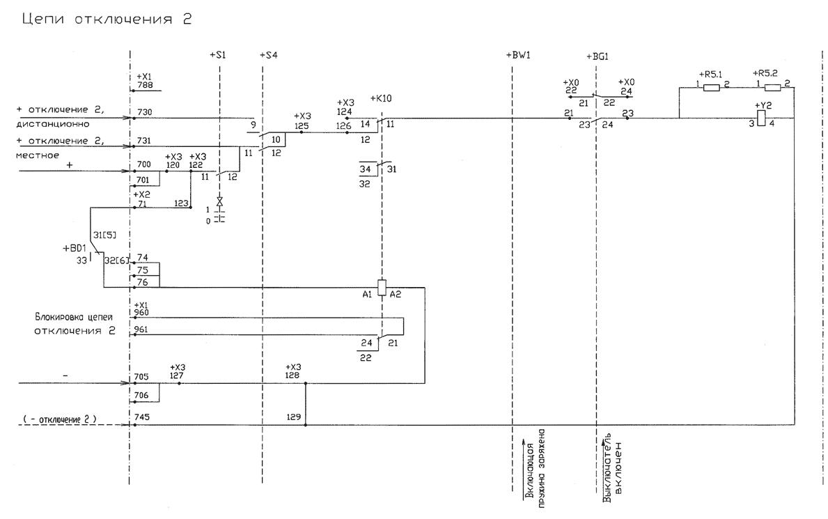
+BW1 +BG1 TRIP CIRCUIT 1 CIRCUITO DE DISPARO 1 TRIP 1 +, REMOTE DISPARO 1 +, REMOTO TRIP 1 +, LOCAL DISPARO 1 +, LOCAL 21[3] 21[3] 21[3] +BD1 +BD2 +BD3 22[4] 22[4] 22[4] CLOSE & TRIP CIRCUIT 1 BLOCKED CIRCUITOS DE CIERRE Y DISPARO 1 BLOQUEO (TRIP 1 -) -
Page 202
TRIP CIRCUIT 2 +BW1 +BG1 CIRCUITO DE DISPARO 2 TRIP 2 +, REMOTE +K10 DISPARO 2 +, REMOTO TRIP 2 +, LOCAL DISPARO 2 +, LOCAL 31[5] 31[5] 31[5] +BD1 +BD2 +BD3 32[6] 32[6] 32[6] TRIP CIRCUIT 2 BLOCKED CIRCUITO DE DISPARO 2 BLOQUEO (TRIP 2 -) (DISPARO 2 -) 1HSB 543206-XBY… -
Page 203
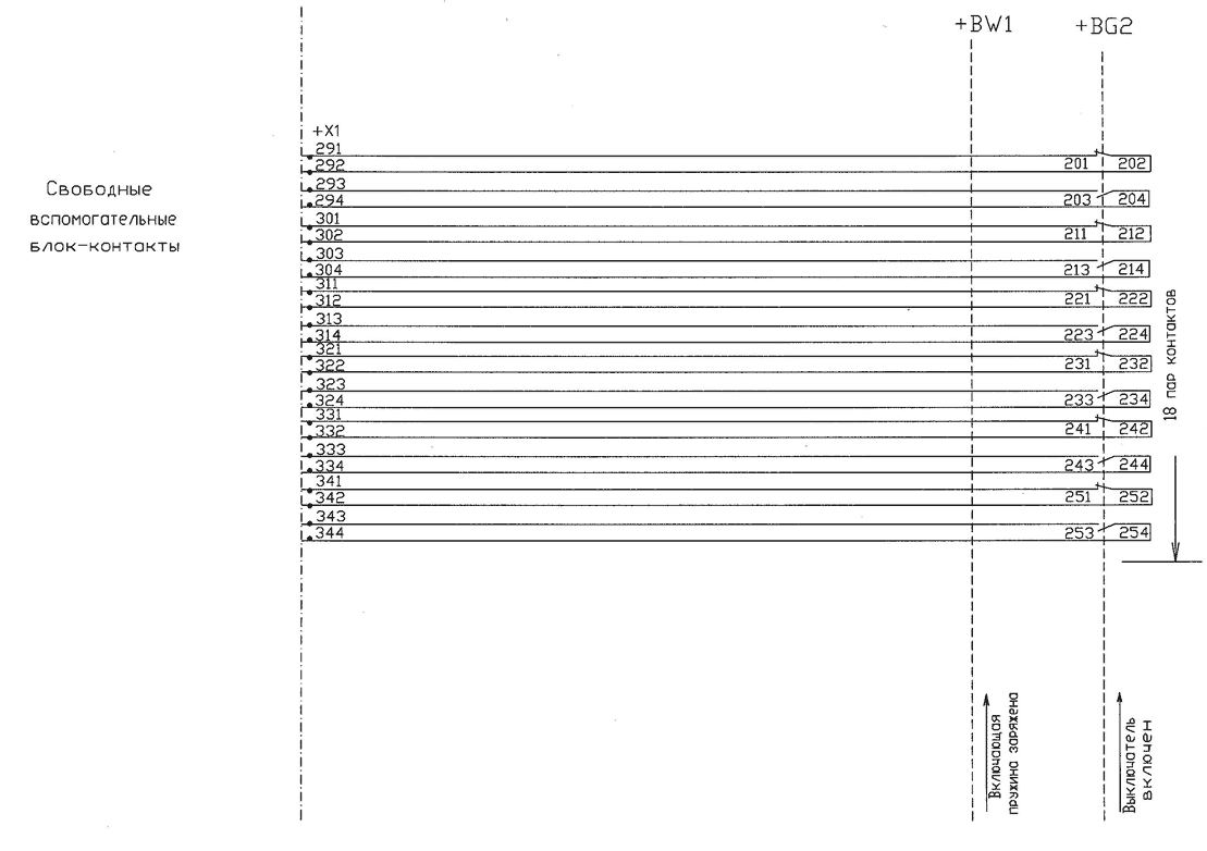
+BW1 +BG1 SIGNAL CONTACTS CONTACTOS DE SENALIZACION REMOTE REMOTO LOCAL LOCAL DISCONN. DESCON. 11[1] 11[1] 11[1] +BD1 +BD2 +BD3 12[2] 12[2] 12[2] +K25 AUXILIARY CONTACTS CONTACTOS AUXILIARES REMOVE LINKS IF ONLY CONDITION MONITORING CONTACTS IMPULSE CONTACT IS NEEDED CONTACTOS DE VERIFICACION REMUEVA LOS ACOPLAMIENTOS SI SOLAMENTE DE POSICION EL CONTACTO DEL IMPULSO ES NECESARIO… -
Page 204
+BW1 +BG1 AUXILIARY CONTACTS CONTACTOS AUXILIARES 12-POLE 12-POLOS 1HSB 543206-XBY 2009-11-24 Hellsten Sara Circuit Diagram DIAGRAMA DE CIRCUITO Based on Prepared 2011-09-23 Gutman Anton OPERATING MECHANISM BLG1002A +BLG.1 Approved MANÖVERDON BLG1002A PPHB/BOD Resp dept Rev ind Lang Sheet 1HSB543206-XBY Cont… -
Page 205
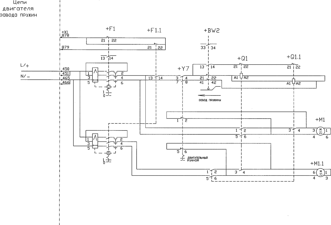
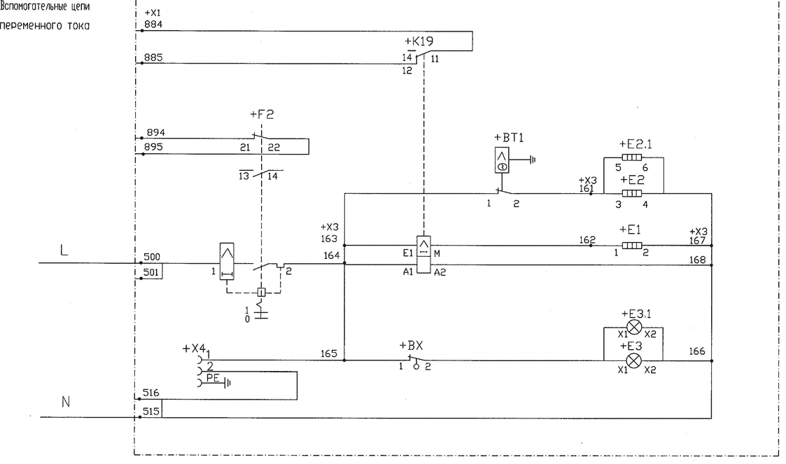
+BW2 MOTOR CIRCUIT CIRCUITO DE MOTOR L / + N / — SPRING CHARGED RESORTE TENSADO MOTOR HAND +BT1 AC AUX. CIRCUIT CIRCUITO AUX. CA +E3.1 1HSB 543206-XBY 2009-11-24 Hellsten Sara Circuit Diagram DIAGRAMA DE CIRCUITO Based on Prepared 2011-09-23 Gutman Anton OPERATING MECHANISM BLG1002A +BLG.1… -
Page 206
CIRCUIT DIAGRAM SHOWS OPERATING MECHANISM WHEN CIRCUIT BREAKER IS IN OFF POSITION, NOT PRESSURIZED, CLOSING SPRING UNCHARGED, HANDCRANK ADAPTED AND CIRCUITS DE-ENERGIZED. DIAGRAMA MUESTRA EL MECÁNISMO DE MANIOBRA CUANDO EL INTERRUPTOR CORRESPONDIENTE DE ALTA TENSION ESTAN POSICION ABIERTA, NO PRESURISADO, LOS RESORTES DEL MECANISMO NO ESTAN TENSADOS, CON LA MANIVELA APLICADA Y BOBINAS DESENERGIZADAS. -
Page 207
TERMINAL ARRANGEMENT (VERTICAL MOUNT.) (UPPER RAIL) DISPOSICION DE TERMINALES (MONTAJE VERTICAL) (BARRA SUPERIOR) TERMINAL ARRANGEMENT (VERTICAL MOUNT.) (LOWER RAIL) DISPOSICION DE TERMINALES (MONTAJE VERTICAL) (BARRA INFERIOR) TERMINAL ARRANGEMENT (HORIZONTAL MOUNT.) (INTERNAL TERMINALS) DISPOSICION DE TERMINALES (MONTAJE HORIZONTAL) (TERMINALES INTERNA) 1HSB 543206-XBY 2009-11-24 Hellsten Sara Circuit Diagram… -
Page 208
List of Revisions Prepared Approved Rev Index Revision text Date Symbols in project updated and terminal arr adjusted. 2009-06-11 Hellsten Sara Ruthström Jan Switches changed to Kraus & Naimer. 2009-11-27 Hellsten Sara Ruthström Jan 1HSB 543206-XBY 2009-11-24 Hellsten Sara Circuit Diagram DIAGRAMA DE CIRCUITO Based on Prepared… -
Page 211
CIRCUIT DIAGRAM SHOWS OPERATING MECHANISM WHEN CIRCUIT BREAKER IS OPEN, WITHOUT PRESSURE, CLOSING SPRING NOT CHARGED AND HANDCRANK ADAPTED. CIRCUIT BREAKER EL DIAGRAMA DE CIRCUITO MUESTRA EL MECÁNISMO DE OPERACION CUANDO EL INTERRUPTOR ESTA EN POSICION ABIERTO, NO PRESURIZADO INTERRUPTOR CLOSE CIRCUIT LOS RESORTES DE DESCARGADOS Y CON LA MANIVELA APLICADA. -
Page 212
+BG1 TRIP CIRCUIT 2 CIRCUITO DE DISPARO 2 TRIP CIRCUIT SUPERVISION +XC11 SUPERVISION DE CIRCUITO DE DISPARO TRIP 2 + DISPARO 2 + 31[5] +BD1 32[6] +XC11 TRIP 2 — DISPARO 2 — +BW1.1 +BW1.2 +BW2.1 +BW2.2 SPRING DISCHARGED RESORTE DESCARGADO MOTOR CONTACTOR CONTACTOR DE MOTOR 11[1]… -
Page 213
+BG1 +XC11 SIGNAL CONTACTS CONTACTOS DE SENALIZACION CONDITION MONITORING CONTACTS CONTACTOS DE VERIFICACION DE POSICION AUXILIARY CONTACTS +XC12 CONTACTOS AUXILIARES 2011-08-18 Hedberg Reine Circuit Diagram DIAGRAMA DE CIRCUITO Based on Prepared 2011-09-14 Johansson Sören OPERATING MECHANISM BLK +BLK.1 Approved MECANISMO DE OPERACAO BLK PPHB/BOD Resp dept Rev ind… -
Page 214
MOTOR CIRCUIT CIRCUITO DE MOTOR MOTOR CONTACTOR L / + +XC11 CONTACTOR DE MOTOR L / + MOTOR CONTACTOR N / — CONTACTOR DE MOTOR N / — +BT1 AC AUX. CIRCUIT CIRCUITO AUX. CA +XC1 +XC2 2011-08-18 Hedberg Reine Circuit Diagram DIAGRAMA DE CIRCUITO Based on… -
Page 215
CIRCUIT DIAGRAM SHOWS OPERATING MECHANISM WHEN CIRCUIT BREAKER IS OPEN, WITHOUT PRESSURE, CLOSING SPRING NOT CHARGED AND HANDCRANK ADAPTED. EL DIAGRAMA DE CIRCUITO MUESTRA EL MECÁNISMO DE OPERACION CUANDO EL INTERRUPTOR ESTA EN POSICION ABIERTO, NO PRESURIZADO LOS RESORTES DE DESCARGADOS Y CON LA MANIVELA APLICADA. ITEM DESIGNATION ITEM… -
Page 216
We reserve all rights in this document and in the in- formation contained therein. Reproduction, use or disclosure to third parties without express authority is strictly forbidden. c ABB INT.2 INT.1 EXT. INT. +XC1 +XC2 +XC12 +XC12 +XC11 +XC11… -
Page 217
List of Revisions Prepared Approved Rev Index Revision text Date First edition. 2009-07-01 Arnberg Mikael Winther Per Update configuration in project. 2009-07-02 Arnberg Mikael Winther Per Wire data changed 2009-09-07 Arnberg Mikael Winther Per X3 terminals added. 2009-12-02 Sjöström Björn Winther Per X3 deleted, XC11-12 redrawn, X0:43-44 added. -
Page 218
CLOSE CIRCUIT CIRCUIT DIAGRAM SHOWS OPERATING MECHANISM WHEN CIRCUIT BREAKER IS OPEN, WITHOUT PRESSURE, CLOSING SPRING NOT CHARGED AND HANDCRANK ADAPTED. EL DIAGRAMA DE CIRCUITO MUESTRA EL MECÁNISMO DE OPERACION CUANDO EL INTERRUPTOR ESTA EN POSICION ABIERTO, NO PRESURIZADO CIRCUIT BREAKER CIRCUITO DE CIERRE LOS RESORTES DE DESCARGADOS Y CON LA MANIVELA APLICADA. -
Page 219
TRIP CIRCUIT 1 CIRCUITO DE DISPARO 1 +K11 +BG1 +XC21 TCS, POLE — A TCS, POLO-A TCS, POLE — B TCS, POLO-B TCS, POLE — C TCS, POLO-C TRIP 1 +, REMOTE, POLE-A DISPARO 1 +, REMOTO, POLO-A TRIP 1 +, REMOTE, POLE-B DISPARO 1 +, REMOTO, POLO-B TRIP 1 +, REMOTE, POLE-C DISPARO 1 +, REMOTO, POLO-C… -
Page 220
TRIP CIRCUIT 2 CIRCUITO DE DISPARO 2 +XC21 +BG1 TCS, POLE — A TCS, POLO-A TCS, POLE — B TCS, POLO-B TCS, POLE — C TCS, POLO-C TRIP 2 +, REMOTE, POLE-A DISPARO 2 +, REMOTO, POLO-A TRIP 2 +, REMOTE, POLE-B DISPARO 2 +, REMOTO, POLO-B TRIP 2 +, REMOTE, POLE-C DISPARO 2 +, REMOTO, POLO-C… -
Page 221
+K12.C +K13 +K12.B +K12.A +XC21 +BW1.1 +BW1.2 +BW2.1 +BW2.2 +XC21 +Q1.A +XC21 +Q1.B +Q1.C +XC21 1HSB543212-GKG 2011-09-16 Gutman Anton Circuit Diagram DIAGRAMA DE CIRCUITO Based on Prepared 2011-09-23 Stark Mikael OPERATING MECHANISM BLK +BLK.1 Approved MECANISMO DE OPERACION BLK PPHB/BOD Resp dept Rev ind Lang… -
Page 222
+K12.A +K12.B +K12.C +K13 886a 887a 886b 887b 886c 887c 888a 889a 888b 889b 888c 889c 1HSB543212-GKG 2011-09-16 Gutman Anton Circuit Diagram DIAGRAMA DE CIRCUITO Based on Prepared 2011-09-23 Stark Mikael OPERATING MECHANISM BLK +BLK.1 Approved MECANISMO DE OPERACION BLK PPHB/BOD Resp dept Rev ind… -
Page 223
SIGNAL CONTACTS CONTACTOS DE SENALIZACION REMOTE REMOTO LOCAL LOCAL DISCONN. DESCON. 11[1] +XC21 +BD1 12[2] +K25 AUXILIARY CONTACTS CONTACTOS AUXILIARES +XC21 191a 192a 190b 191b CONDITION MONITORING CONTACTS CONTACTOS DE VERIFICACION 192b DE POSICION 199b +XC21 191c 192c +XC22 +XC22 +XC22 +XC22 1HSB543212-GKG… -
Page 224
AUXILIARY CONTACTS +XC22 +BG1 CONTACTOS AUXILIARES 1HSB543212-GKG 2011-09-16 Gutman Anton Circuit Diagram DIAGRAMA DE CIRCUITO Based on Prepared 2011-09-23 Stark Mikael OPERATING MECHANISM BLK +BLK.1 Approved MECANISMO DE OPERACION BLK PPHB/BOD Resp dept Rev ind Lang 7 14 Sheet 1HSB543212-GKV Cont… -
Page 225
AUXILIARY CONTACTS CONTACTOS AUXILIARES +XC22 +XC22 +XC22 +XC22 +XC22 +XC22 1HSB543212-GKG 2011-09-16 Gutman Anton Circuit Diagram DIAGRAMA DE CIRCUITO Based on Prepared 2011-09-23 Stark Mikael OPERATING MECHANISM BLK +BLK.1 Approved MECANISMO DE OPERACION BLK PPHB/BOD Resp dept Rev ind Lang 8 14 Sheet 1HSB543212-GKV… -
Page 226
+Q1.A +Q1.C +Q1.B MOTOR CIRCUIT CIRCUITO DE MOTOR +F1.A 878a 879a +F1.B 878b 879b +F1.C 878c 879c L / + +XC21 N / — +XC21 1HSB543212-GKG 2011-09-16 Gutman Anton Circuit Diagram DIAGRAMA DE CIRCUITO Based on Prepared 2011-09-23 Stark Mikael OPERATING MECHANISM BLK +BLK.1 Approved… -
Page 227
AC AUX. CIRCUIT CIRCUITO AUX. CA +BT1 +XC1 +XC21 +XC2 +XC21 +XC1 +BX1 +XC2 1HSB543212-GKG 2011-09-16 Gutman Anton Circuit Diagram DIAGRAMA DE CIRCUITO Based on Prepared 2011-09-23 Stark Mikael OPERATING MECHANISM BLK +BLK.1 Approved MECANISMO DE OPERACION BLK PPHB/BOD Resp dept Rev ind Lang 10 14… -
Page 228
CIRCUIT DIAGRAM SHOWS OPERATING MECHANISM WHEN CIRCUIT BREAKER IS OPEN, WITHOUT PRESSURE, CLOSING SPRING NOT CHARGED AND HANDCRANK ADAPTED. EL DIAGRAMA DE CIRCUITO MUESTRA EL MECÁNISMO DE OPERACION CUANDO EL INTERRUPTOR ESTA EN POSICION ABIERTO, NO PRESURIZADO LOS RESORTES DE DESCARGADOS Y CON LA MANIVELA APLICADA. ITEM DESIGNATION ITEM… -
Page 229
TERMINAL ARRANGEMENT (VERTICAL MOUNT.) DISPOSICION DE BORNERAS (MONTAJE VERTICAL) 1HSB543212-GKG 2011-09-16 Gutman Anton Circuit Diagram DIAGRAMA DE CIRCUITO Based on Prepared 2011-09-23 Stark Mikael OPERATING MECHANISM BLK +BLK.1 Approved MECANISMO DE OPERACION BLK PPHB/BOD Resp dept Rev ind Lang 12 14 Sheet 1HSB543212-GKV Cont… -
Page 230
TERMINAL ARRANGEMENT (VERTICAL MOUNT.) (INTERNAL) DISPOSICION DE BORNERAS (MONTAJE VERTICAL) (INTERNA) 1HSB543212-GKG 2011-09-16 Gutman Anton Circuit Diagram DIAGRAMA DE CIRCUITO Based on Prepared 2011-09-23 Stark Mikael OPERATING MECHANISM BLK +BLK.1 Approved MECANISMO DE OPERACION BLK PPHB/BOD Resp dept Rev ind Lang 13 14 Sheet… -
Page 231
List of Revisions Prepared Approved Rev Index Revision text Date First edition 2011-09-23 Gutman Anton Stark Mikael 1HSB543212-GKG 2011-09-16 Gutman Anton Circuit Diagram DIAGRAMA DE CIRCUITO Based on Prepared 2011-09-23 Stark Mikael OPERATING MECHANISM BLK Approved MECANISMO DE OPERACION BLK PPHB/BOD Resp dept Rev ind…
![]()
Страница 16 из 17
Приложение 1.
Выключатель HPL 550B2 с тремя приводами BLG 1002А. Общий вид. Заводская табличка.
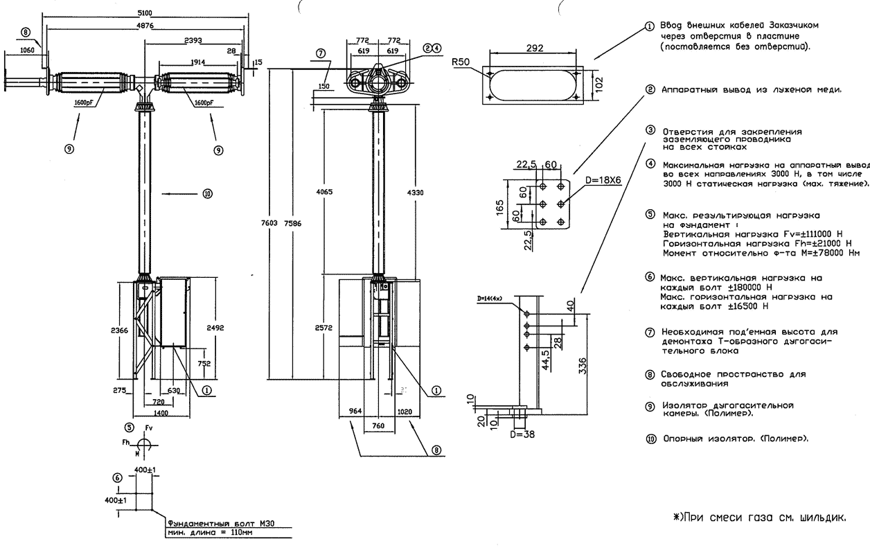
ЗЛЕГАЗОВЫЙ КОЛОНКОВЫЙ ВЫКЛЮЧАТЕЛЬ HPL 550B2 ДВУХРАЗРЫВНЫЙ С ТРЕМЯ ПРУЖИННЫМИ ПРИВОДАМИ BLG 1002А
ГАБАРИТНО-УСТАНОВОЧНЫЙ ЧЕРТЕЖ

Приложение 2.
Привод BLG 1002А выключателя HPL 550B2. Схема электрическая принципиальная.

Схема управления привода выключателя в положении ‘ΌΤΚΛ», пружина не заряжена, элегаз вез давления, при вставленной рукоятке ручного взвода.
ПРИНЦИПИАЛЬНАЯ СХЕМА УПРАВЛЕНИЯ
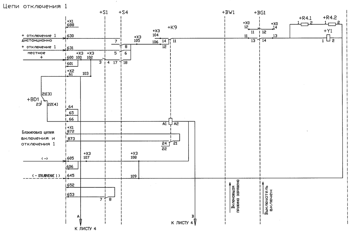
ЭЛЕГАЗОВЫЙ КОЛОНКОВЫЙ ВЫКЛЮЧАТЕЛЬ С ПОПОЛЮСНЫМ УПРАВЛЕНИЕМ ПРИВОД ПОЛЮСА ВЫКЛЮЧАТЕЛЯ BLG-1002A
ПРИНЦИПИАЛЬНАЯ СХЕМА УПРАВЛЕНИЯ


| № |
Обозном. |
Наименование |
Кол, |
Прим, |
|
1 |
BD1-BD3 |
Контакт монитора плотности элегаза, 220 В |
3 |
|
|
2 |
BGl, BG2 |
Вспомогательные Блок-контакты выключателя HSV 246, 220 В, 4 А |
2 |
|
|
3 |
BN |
Счетчик 220 В, 25 Вт |
1 |
|
|
4 |
ВТ1 |
Термостат, ~220 В |
1 |
|
|
5 |
BW1, BW2 |
Концевой выключатель пружин, 220 В |
2 |
|
|
6 |
вх |
Концевой выключатель двери шкафа, ~220 В |
1 |
|
|
7 |
Е1 |
Антиконденсационный нагревательный элемент, (включен постоянно), 220 В, 70 Вт |
1 |
|
|
8 |
Е2, Е2.1 |
Нагревательный элемент (управление от термостата), 220 В, 140 Вт |
2 |
|
|
9 |
m |
Лампа освещения, ~ 220 В |
2 |
|
|
10 |
Fl, П.1 |
Автоматический выключатель двигателя MS225, 4 А, 400 В |
2 |
|
|
11 |
F2 |
Автоматический выключатель нагревателей S201RB10, 10 Ад 220-250 В |
1 |
|
|
12 |
HI |
Лампа сигнализации положения выключателя |
1 |
|
|
13 |
НЗ |
Лампа сигнализации положения выключателя (красн.) |
1 |
|
|
14 |
КЗ |
Реле Блокировки от многократных включении С5 А30, 220 В, 1,4 Вт |
1 |
|
|
15 |
К9 |
Реле Блокировки вкл./откл. 1 при низкой плотности газа С5 А30, 220 В, 1,4 Вт |
1 |
|
|
16 |
К10 |
Реле Блокировки отключения 2 при низкой плотности газа С5 А30, 220 В, 1,4 Вт |
1 |
|
|
17 |
К19 |
Токовое реле контроля цепей подогрева “230-240 В; гистерезис 40% Т2=10с, Т1=1с |
1 |
|
|
18 |
К25 |
Реле-повторитель монитора плотности. |
1 |
|
|
19 |
Ml, М1.1 |
Двигатель завода пружины, STS 80/ /65, 220 В, 1,7 кВт |
2 |
|
|
20 |
Ql, Q1.1 |
Контактор, DIL 00 AM-G-01, “/=220 В, 10 А |
2 |
|
|
N0 |
Обознач., |
Наименование |
Кол, |
Прим, |
|
21 |
R3.1, R3.2 |
Шунтирующее сопротивление для катушки включения, 100 Ом, 17 Вт |
2 |
|
|
22 |
R4.1, R4.2 |
Шунтирующее сопротивление для катушки отключения 1, 150 Ом, 17 Вт |
2 |
|
|
23 |
R5.1, R5.2 |
Шунтирующее сопротивление для катушки отключения 2, 150 Ом, 17 Вт |
2 |
|
|
24 |
R7, R8 |
Резистор к лампе сигнализации положения выключателя |
2 |
|
|
25 |
S1 |
Ключ управления (отключение/включение) PR12, 660 В, 16 А |
1 |
|
|
26 |
S4 |
Переключатель выбора режима (местное/дистанционное) PR12, 660 В, 16 А |
1 |
|
|
27 |
Х0 |
Ряд зажимов (внутренних соединении) М4/6, 750 В, 30 А, 4 кв.мм |
||
|
28 |
XI |
Ряд зажимов (внешних соединении) М6/8, М4/6, 750 В, 61/30 А, 6/4 кв.мм |
||
|
29 |
Х2 |
Ряд зажимов (внутренних соединении), (контроль SF6), М4/6, 750 В, 30 А, 4 кв.мм, |
||
|
30 |
Х3 |
Ряд зажимов (внутренних соединении) М4/6, 750 В, 30 А, 4 кв.мм, |
||
|
31 |
Х4 |
Розетка, ~220 В |
1 |
|
|
32 |
Yl, Y2* |
Катушки отключения 1 и 2, |
2 |
|
|
33 |
Y3* |
Катушка включения, |
1 |
|
|
34 |
Y7 |
Контакт ручной блокировки, M03-04-ND+NC, 250 В, 10 А |
1 |
|
Номинальный ток узла управления (катушка включения/отключения + шунтирующее сопротивление), 2 А.
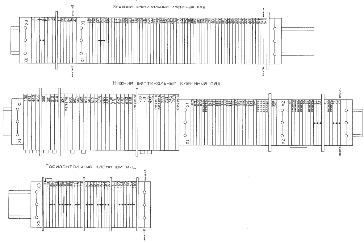
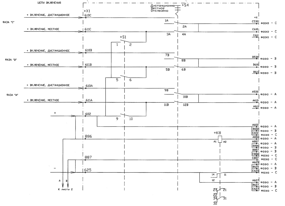
ПРИНЦИПИАЛЬНАЯ ЭЛЕКТРИЧЕСКАЯ СХЕМА
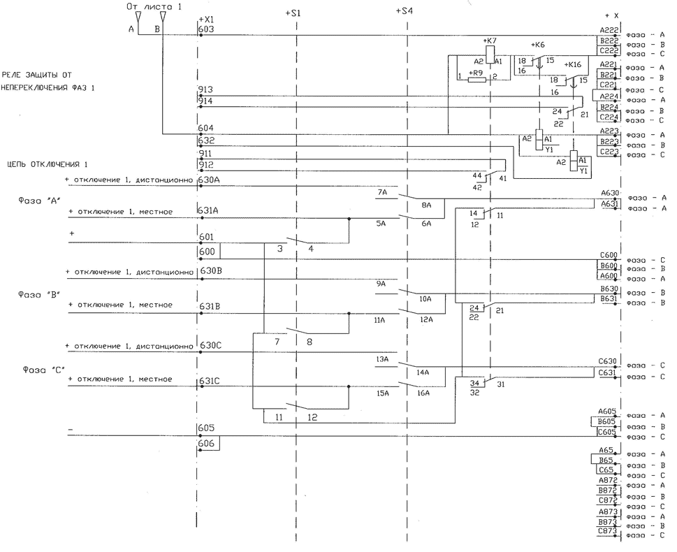

ПРИНЦИПИАЛЬНАЯ ЭЛЕКТРИЧЕСКАЯ СХЕМА

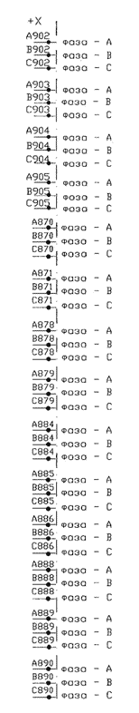
А
С
D


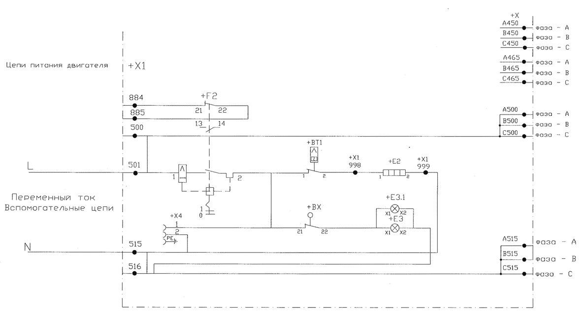
|
NO |
Обознач. |
Наименование |
Кол, |
Примечание |
|
1 |
BT1 |
Термостат, ~230 В, 16 А, уст.+10 |
1 |
|
|
2 |
BX |
Концевой выключатель двери шкафа |
1 |
|
|
3 |
E2 |
Подогреватель, ~230 В, 153 Вт |
1 |
-220В, 140Вт |
|
4 |
E3, E3.1 |
Лампа освещения |
2 |
|
|
5 |
F2 |
Автомат питания подогревателя,440 В, 10 А |
1 |
|
|
6 |
H1 |
Лампа (зеленая/отключено), ~230 В, 5 Вт |
1 |
|
|
7 |
H3 |
Лампа (красная/включено), ~230 В, 5 Вт |
1 |
|
|
8 |
K6 |
Реле времени (с задержкой), уст, 1с ~/=240 В, коммутационная способность 80 Вт |
1 |
для К7 |
|
9 |
K7 |
Промежуточное реле, 220 В, 14 Вт, коммутационная способность 10 А |
1 |
4ср.=20мс |
|
10 |
K8 |
Промежуточное реле, 220 В, 14 Вт, коммутационная способность 16 А |
1 |
|
|
11 |
K13 |
Промежуточное реле, 220 В, 14 Вт, коммутационная способность 10 А |
1 |
tcp.=20MC |
|
12 |
K15 |
Реле времени (с задержкой), уст. 1с, ~/=:240В, коммутационная способность 80 Вт |
1 |
для К13 |
|
13 |
K16 |
Реле времени(с задержкой), уст, 0,1с, ~/=240В, коммутационная способность 80 Вт |
1 |
для К7 |
|
14 |
R7, R8 |
Резистор к лампам H1, Н3, 15 кОм, 17 Вт |
2 |
|
|
15 |
R9 |
Шунтирующий резистор для реле запиты от неперекл. Фаз, 6,8 кОм, 17 Вт |
1 |
для К7 |
|
16 |
RIO |
Шунтирующий резистор для реле запиты от неперекл, Фаз, &,8 кОм, 17 Вт |
1 |
для К13 |
|
17 |
S1 |
Ключ управления (включить/отключить) |
1 |
|
|
18 |
S4 |
Ключ выбора режима (местное/дистанционное) |
1 |
|
|
19 |
X(A,B,C) |
Ряд зажимов (ряд 1, ряд 2, ряд 3) |
3 |
|
|
20 |
X1 |
Ряд зажимов (ряд 4) |
1 |
|
|
21 |
X4 |
Розетка |
1 |
|
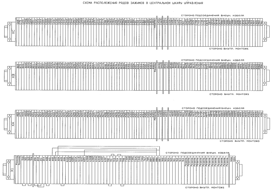
![]()
Механизм управления элегазовых выключателей ABB с приводом BLG
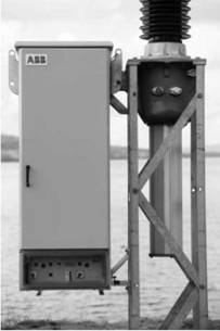
Выключатели являются последним звеном в цепи используемого оборудования, составляющего защитное оборудование системы энергоснабжения. Привод должен в течение нескольких миллисекунд выработать энергию, необходимую для преобразования выключателя из идеального проводника в идеальный изолятор. Отказ привода часто означает невыполнение операции отключения в целом, Таким образом, приводы играют особо важную роль в обеспечении надежности выключателя, а, следовательно, и системы энергоснабжения в целом.
Кроме того, все чаще приходится решать задачи коммутации конденсаторных батарей и реакторов, а это вынуждает предъявлять повышенные требования к эксплуатационной износостойкости оборудования.
Международные исследования показали, что восемьдесят процентов (80%) всех отказов высоковольтных выключателей происходят из-за отказов приводов. Поэтому для достижения высочайшей степени эксплуатационной надежности выключатели следует оснащать высоконадежными приводами.
После поставки более 50000 приводов BLG компания АББ уверена в том, что конструкция данного привода является одной из самых надежных на рынке. Его конструкция гарантирует высокую степень общей надежности и практически не требует обслуживания привода, а значит и всего выключателя.
Области применения
LTB E1 (с трехполюсным режимом привода) LTB E2 LTB E4
Особенности конструкции
Пружины отключения составляют часть кинематической системы исполнительных механизмов выключателя и размещаются под корпусом механизма. При этом механическая энергия, необходимая для выполнения основной операции отключения, запасена в пружинах отключения все время, пока выключатель находится во включенном положении. Другими словами, включенный выключатель всегда готов к немедленному отключению.
Универсальные электродвигатели вращают редуктор взвода пружины и через него автоматически взводят пружины отключения сразу после выполнения каждой операции включения. Пружины удерживаются во взведенном состоянии защелкой, которая освобождается, когда выполняется операция включения выключателя. Это обеспечивает быстрое обратное включение выключателя по истечении времени бездействия 0,3 сек.
Принцип действия привода можно кратко описать следующим образом. Диск с кулачком и система пружин связаны друг с другом кольцевой цепью. Цепь, имеющая две ветви, охватывает звездочку на валу электродвигателя, передает энергию для взвода пружин, а также вращает диск с кулачком при выполнении операции включения выключателя.
Во время этого вращения диск с кулачком приводит в движение передаточный механизм, преобразующий вращательное движение в поступательное.
Демпфирующее устройство замедляет движение контактов в конечном положении.
Вспомогательное оборудование имеет следующие характеристики:
• износостойкие вспомогательные контакты и конечные выключатели;
• механический указатель состояния взвода, частичного взвода или отсутствия взвода пружины включения;
• весь электромонтаж для подключения внешних соединений выведен на клеммные колодки.
Одинаковое время срабатывания при любых условиях окружающей среды делает выключатель весьма удобным для управляемой коммутации.
Блокировка непреднамеренного срабатывания
При использовании вышеописанной системы блокировки в рабочем состоянии исключена возможность выполнения следующих операций:
• операция включения, когда выключатель уже включен (т.н. «потерянный» ход);
• операция включения во время операции отключения.
Корпус привода BLG
• Передняя и задняя дверцы, оборудованные дверными фиксаторами и приспособлением для висячего замка на дверных ручках.
• Изолированные дверцы и стенки, обеспечивающие снижение потребляемой энергии и уровня шумов.
Панели
• местный переключатель «Включить/Отключить»;
• 3-х позиционный переключатель режима управления «Местное/Дистанционное/ Отключено»;
• несбрасываемый электромеханический счетчик числа срабатываний выключателя;
• механический индикатор взвода пружины, видимый через прозрачную шторку.
За задней дверцей корпуса привода находится интерфейсная панель, снабженная всеми необходимыми клеммными колодками для подключения заказчиком внешних соединений. В стандартной комплектации устанавливается следующее оборудование:
• стандартные клеммные колодки зажимного типа, в которых оголенный провод зажимается в клемме между двумя металлическими пластинами;
• блокировка для ручного взвода пружин;
• аппаратура управления — реле, автоматические микровыключатели, контакторы и т.д.;
На внутренней стороне задней дверцы находится отсек для документов с инструкциями по эксплуатации и окончательными вариантами чертежей. Там же закреплена и рукоятка для взвода.

Центральный шкаф управления (CCC)
Включенное положение
Выключатель удерживается во включенном положении защелкой отключения (1), которая воспринимает усилие, оказываемое взведенной отключающей пружиной.
В таком состоянии привод готов произвести выключение по команде на отключение и может быстро выполнить полный цикл автоматического повторного включения (Отключение — 0,3 с — Включение).
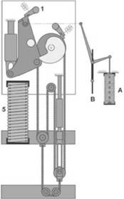
Операция отключения
Отключающая пружина (A) перемещает подвижный элемент выключателя (B) в отключенное положение. Рабочий рычаг (2) перемещается вправо и в конце своего хода упирается в диск с кулачком (3).
Движение системы контактов амортизируется в конце хода масляным демпфирующим устройством (4).

Операция включения
Звездочка (7) фиксируется и не вращается, вследствие чего энергия, запасенная во включающих пружинах, передается через ветвь кольцевой цепи (8) на звездочку (11), укрепленную на диске с кулачком (3).
Диск с кулачком при этом перемещает рабочий рычаг (2) влево, где он фиксируется в конечном положении отключающей защелкой (1).
На конечном участке вращение диска с кулачком замедляется при помощи демпфирующего устройства (9), а фиксирующая защелка на звездочке (11) снова возвращается в исходное положение, упираясь во включающую защелку (6).
Взвод пружин включения
Звездочка (11), укрепленная на диске с кулачком (3), имеет собственную защелку, которая зацепляется за включающую защелку (6), после чего ветви цепи (8) поднимают перекладину с пружиной (10).
Включающие пружины (5) при этом сжимаются, и исполнительный механизм снова приходит в нормальное рабочее положение.
Источник
HPL 550B2 руководство по эксплуатации выключателей — Схемы и рисунки
Содержание материала
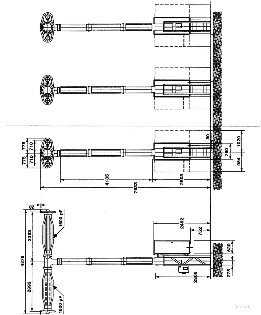
Рис.4-1. Выключатель HPL 550B2.

Рис.4-2. Полюс выключателя HPL 550B2.
- — дугогасительное устройство;
- — опорная изоляция;
- — привод;
- — конденсатор;
- — рама.
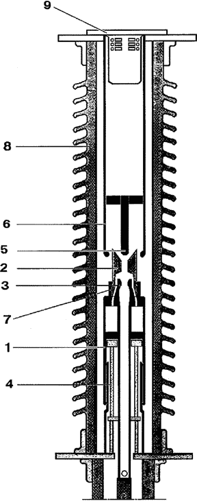
Рис.5-1. Дугогасительный разрыв.
- — поршневой цилиндр;
- — сопло;
- — подвижный дугогасительный контакт;
- — поршень;
- — неподвижный дугогасительный контакт;
- — неподвижный главный контакт;
- — подвижный главный контакт;
- — изолятор;
- — крышка.
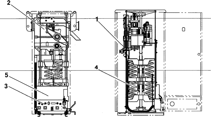
Рис.5-2. Привод.
- — узел завода пружин;
- — приводной механизм;
- — панель управления;
- — включающие пружины;
- — подогреватели (за защитной стенкой).

Рис.5-3. Нормальное положение привода.
- — отключающая пружина;
- — включающие пружины;
- — отключающее запорное устройство.

Рис.5-4. Операция отключения.
- — отключающее запорное устройство;
- — отключающая пружина;
- — тяга;
- — оперативный рычаг;
- — амортизатор отключения;
- — кулачковый диск;
- — включающие пружины.

Рис.5-5. Операция включения.
- — включающее запорное устройство;
- — секция цепи;
- — включающие пружины;
- — кулачковый диск;
- — оперативный рычаг;
- — отключающее запорное устройство;
- — амортизатор включения;
- — отключающая пружина;
- — тяга;
- — секция цепи.
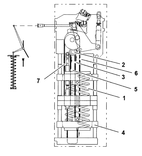
Рис.5-6. Заводка включающих пружин.
- — включающие пружины;
- — ведущая звездочка;
- — секция цепи;
- — ярмо пружин;
- — секция цепи;
- — секция цепи;
- — секция цепи.
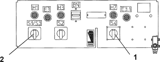
Рис. 5.7. Панель управления привода
- — переключатель «Местое/Дистанционное/Цепь разорвана»;
- — ключ «Включить/Отключить».

Рис.5-8. Узел завода пружин (1).
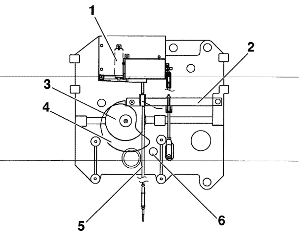
Рис.5-9. Механическая блокировка.
- — концевой выключатель;
- — блокирующая рейка;
- — блокирующий диск;
- — кулачковый диск;
- — оперативная тяга;
- — вал оперативного рычага.

Рис.5-10. Запорные устройства (1).

Рис.5-11. Амортизаторы включения (1) и отключения (2).

Рис.5-12. Узел вспомогательных блок-контактов
- — вспомогательные блок-контакты;
- — тяга.

Рис.5-13. Подогреватель (1).
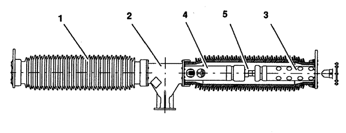
Рис.6-1. Дугогасительное устройство.
- — изолятор;
- — верхний механизм;
- — верхний токопровод;
- — нижний токопровод;
- — поршень.

Рис.6-2. Опорная изоляция.
- — верхний опорный изолятор;
- — нижний опорный изолятор;
- — оперативная тяга;
- — верхняя направляющая;
- — фланец.
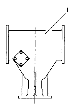
Рис.6-3. Верхний механизм (1).
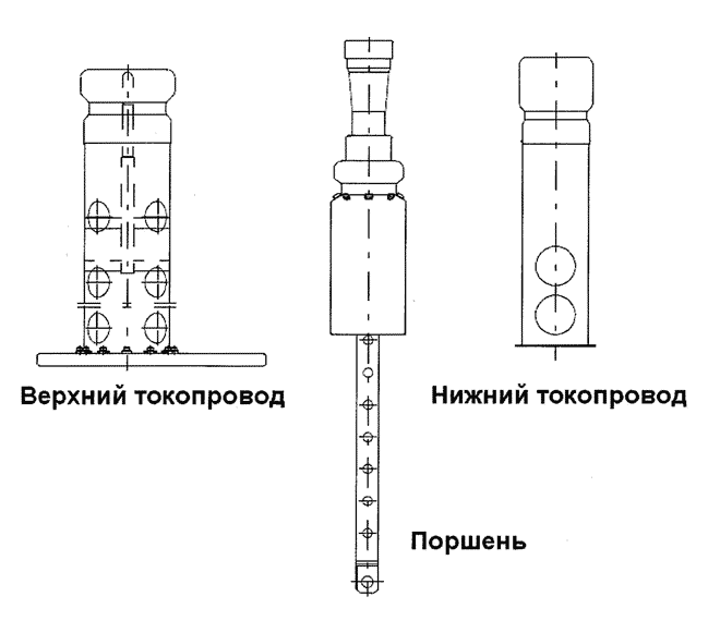
Рис.6-4. Комплект контактов.

Рис.6-5. Приводной механизм полюса (1).

Рис.6-6. Отключающий механизм (1).

Рис.6-7. Контейнер (1) с адсорбентом (2).
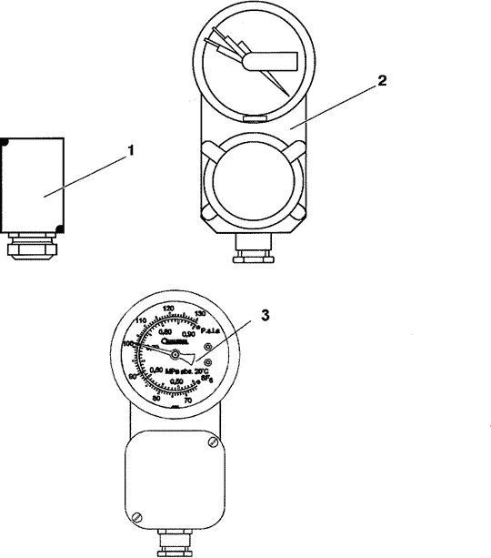
- — с эталонным объемом;
- — с биметаллическим элементом;
- — с биметаллическим элементом (новый образец).

Рис.6-9. Обратный клапан (1).

Рис.6-10. Шунтирующий конденсатор.
- — конденсатор;
- — кронштейн;
- — дистанционная прокладка.

Рис.6-11. Выравнивающее кольцо (1).
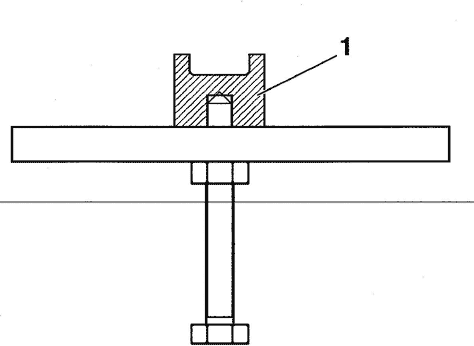
Рис.6-12. Приспособление для отключающего механизма (1).
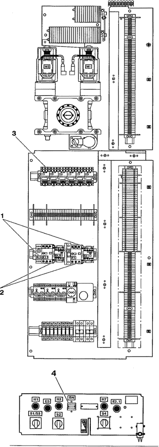
Рис.6-13. Электрическое оборудование привода.
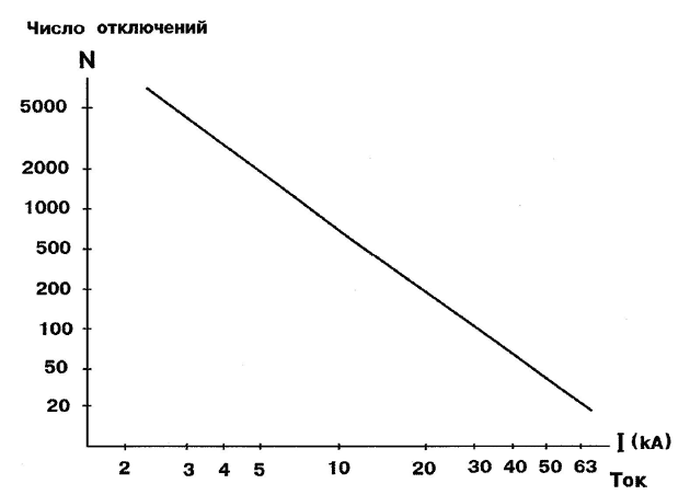
Рис.7-1. Зависимость допустимого числа отключений (N) от тока (I).

Рис.8-1. Заземление шкафа привода.
1 — клемма для заземления.
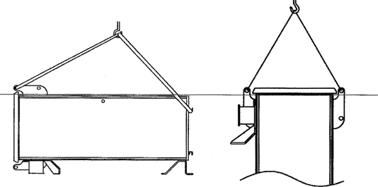
Рис.9-1. Подъем привода.
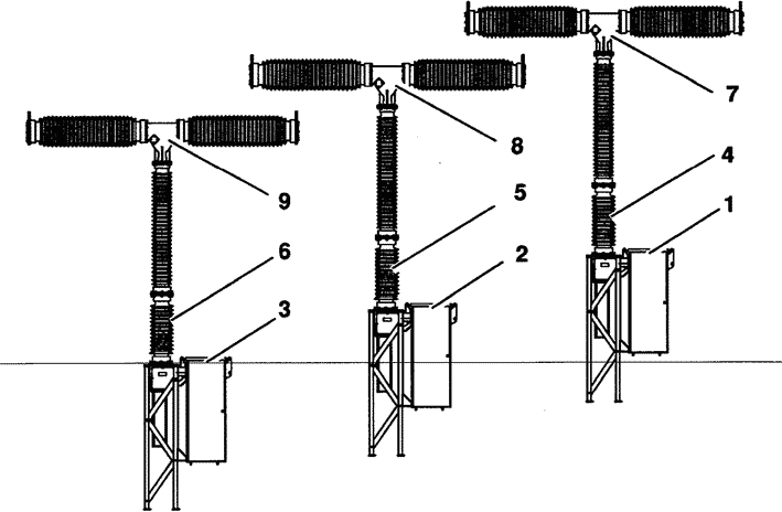
Рис.9-2. Маркировка.
- — привод А1;
- — привод В1;
- — привод С1;
- — опорная изоляция А1;
- — опорная изоляция В1;
- — опорная изоляция С1;
- — дугогасительное устройство А1;
- — дугогасительное устройство В1;
- — дугогасительное устройство С1.
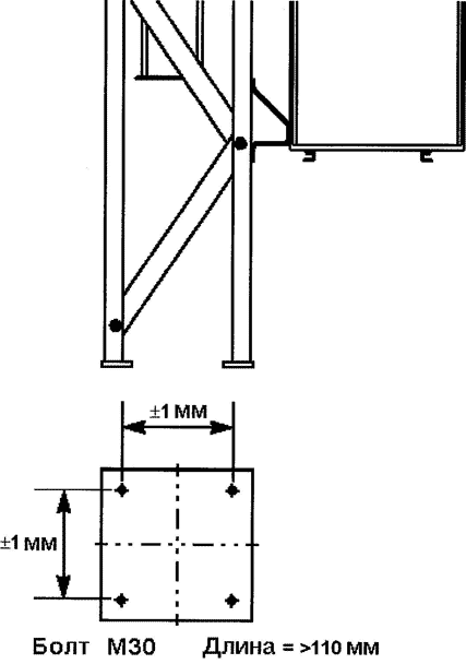
Рис.9-3. Фундамент.

Рис.9-4. Сборка стойки.
- — половина рамы, 2 шт.;
- — поперечина, 6 шт.;
- — болт М20х60; 8 шт., гайка М20, 8 шт.; шайба 21x37x3,16 шт.
Рис.9-5. Монтаж стойки на фундаменте.
- — фундаментный болт, 1_>110 мм (не поставляются);
- — гайка, 24 шт. (не поставляются);
- — шайба, 24 шт.;
- — шайба дистанционная (не поставляются);
- — фундамент;
- — основание стойки.

Рис.9-6. Подъем опорной изоляции.
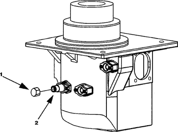
Рис.9-7. Обратный клапан.
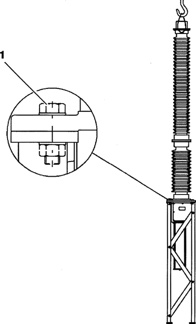
Рис.9-8. Установка опорной изоляции на раме.
- — болт М20х70, 4 шт.; гайка М20, 4 шт.; шайба 21x37x3, 8 шт.

Рис.9-9. Подготовка приводного механизма

Рис.9-10. Установка выравнивающих колец.
- — выравнивающее кольцо, 1 шт.;
- — кронштейн, 4 шт.;
- — болты М10х30, 4 шт., шайбы 10.5x25x4, 8 шт., гайки М10, 4 шт.;
- — болты М10х25, 4 шт., шайбы 10.5x25x4, 4 шт.

Рис.9-11. Установка привода.
1 — болт М12х50, 10 шт.; гайка М12, 10 шт.; шайба 13 х 24 х 2.5, 20 шт.; 2- пружинная шайба 13 х 29 х 3, 4 шт.

Рис.9-12. Окончательная сборка опорной изоляции.

Рис.9-13. Демонтаж транспортных крышек.
- — транспортная крышка с уплотнительным кольцом;
- — болт М12х50, 8 шт.; шайба 13x28x3, 16 шт.; гайка М12, 8 шт.;
- — крышка с двумя уплотнительными кольцами;
- — болт М10х25, 4 шт.; шайба 10.5x22x2, 4 шт.;
- — дугогасительное устройство;
- — транспортная крышка с уплотнительным кольцом;
- — опорная изоляция;
- — блок-шайба.
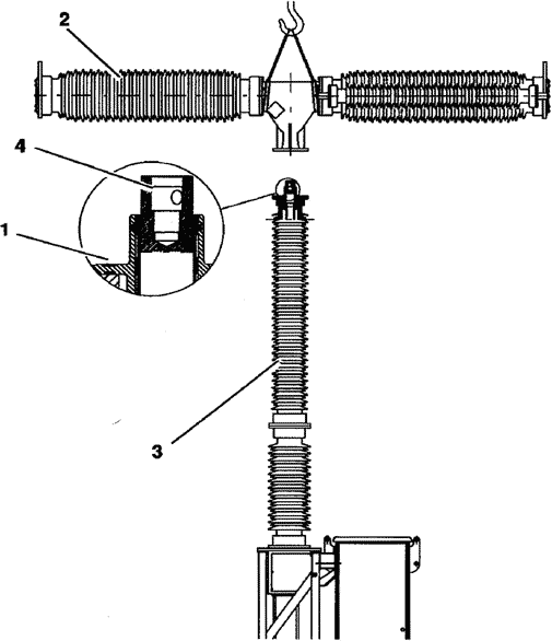
Рис.9-14. Установка дугогасительного устройства.
- — уплотнительное кольцо;
- — дугогасительное устройство;
- — опорная изоляция;
- — оперативная тяга.
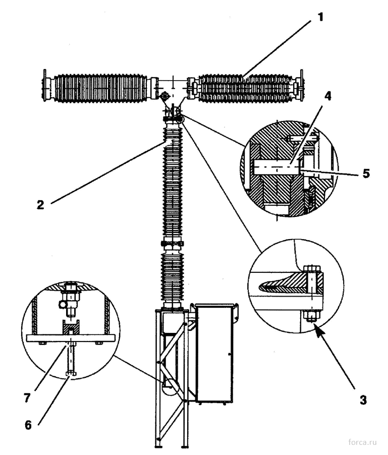
Рис.9-15. Соединение дугогасительного устройства и опорной изоляции.
- — дугогасительное устройство;
- — опорная изоляция;
- — болт М12×80,4 шт.; шайба 13x24x2.5, 8 шт.; гайка М12, 4 шт.;
- — ось, ф 22 мм;
- — стопорное кольцо;
- — регулировочный винт 1 шт.;
- — контргайка, 1 шт.
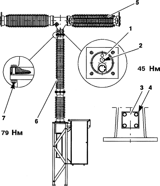
Рис.9-16. Демонтаж блок-шайбы.
- — блок-шайба;
- — болт М8;
- — уплотнительная крышка;
- — болт М10х25;, 4 шт.; шайба 10.5x22x2, 4 шт.;
- — дугогасительное устройство;
- — опорная изоляция;
- — болт М 12×80,4 шт.; шайба 13x24x2.5, 8 шт.; гайка М12, 4 шт.
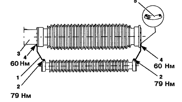
Рис.9-17. Установка конденсатора.
- — кронштейн, 2 шт.;
- — болт М 12×35, 4 шт.; пружинная шайба, 4 шт.;
- — корпус верхнего механизма;
- — болт М12х30, 4 шт.; пружинная шайба, 4 шт.;
- — дистанционная шайба.

Рис.9-18. Установка выравнивающего кольца.
- — болт М12х50, 2 шт.; шайба 13x28x3, 2 шт.;
- — выравнивающее кольцо;
- — болт М10х35, 1 шт.; шайба 10.5x25x4, 2 шт.; гайка М10,1 шт.
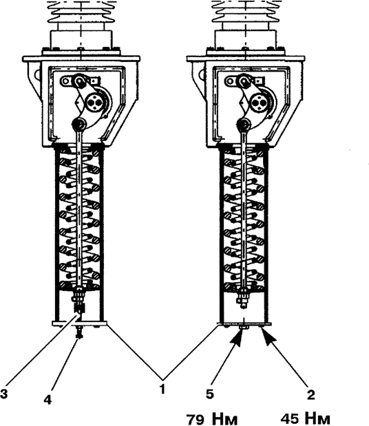
Рис.9-19. Демонтаж разгрузочного приспособления.
- — нижняя крышка;
- — болт М10×50, 4 шт.;
- — приспособление 1HSB446381-A;
- — регулировочный винт;
- — болт М 16×30, 1 шт.; шайба 17x30x3, 1 шт.

Рис.9-20. Проверка блокировки.
- — оперативный рычаг;
- — включающая защелка.

Рис. 9-21. Регулировка привода.
- — блокирующий язычок;
- — отверстие;
- — отверстие.
Рис. 9-22. Установка тяги между приводом и полюсной колонкой.
- — корпус механизма;
- — тяга от привода;
- — оперативный рычаг;
- — наконечник;
- — соединитель;
- — пружинная шайба;
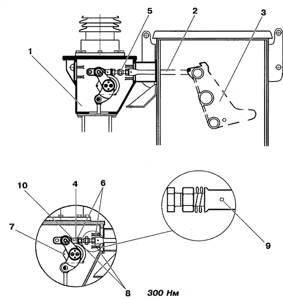
- — контрольное отверстие в рычаге;
- — контргайка;
- — контрольное отверстие в тяге;
- — контрольное отверстие в наконечнике.
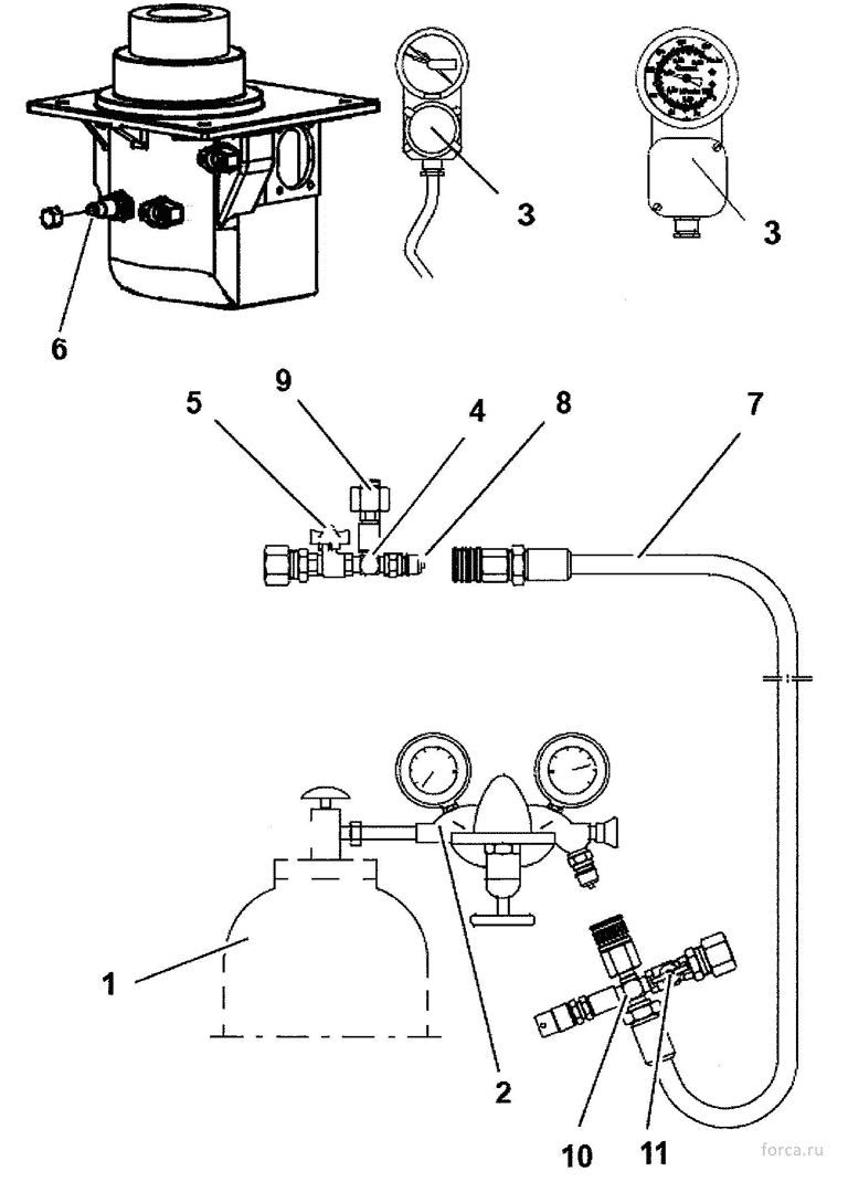
Рис.9-23. Заполнение выключателя газом.
1 — газовый баллон; 8 — адаптер;
2 — регулятор; 9 — ниппель с соединительной гайкой
3 — монитор плотности 10 — переходник;
(старого и нового образца); 11 — клапан.
4 — муфта;
5 — клапан;
6 — газовый клапан выключателя;
7 — шланг;
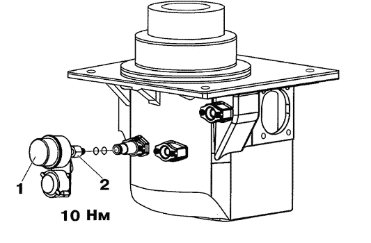
Рис.9-24. Монитор плотности (1) и соединительная гайка (2).
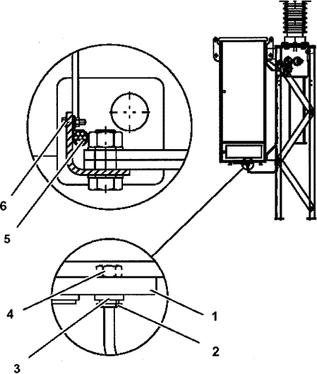
Рис.9-25. Контроль газа.
- — фланец;
- — кабельная муфта;
- — уплотнительная шайба;
- — гайка;
- — скоба, 4 шт.;
- — болт М5х20, 4 шт., гайка М5, 4 шт., шайба 5.3x10x1, 8 шт.

Рис.9-26. Установка указателя и крышек.

- — крышка;
- — болт М12х40, 4 шт.;
- шайба 12x24x2.5, 8 шт.; гайка М12, 4 шт.;
- — указатель;
- — болт М8х16, 9 шт.; шайба 8.4x16x1.5, 9 шт.

Рис.11 -1. Разгрузка тяги.
- — нижняя крышка;
- — болт М16х30, 1 шт.; шайба 2 шт.;
- — приспособление 1HSB446381-A;
- — регулировочный винт;
- — тяга;
- — рычаг.

Рис.11 -2. Демонтаж дугогасительного устройства.
- — дугогасительное устройство;
- — опорная изоляция;
- — крышка с двумя уплотнительными кольцами;
- — болт М 10×25, 4 шт.; шайба 10.5x22x2, 4 шт.;
- — блок-шайба;
- — стопорное кольцо;
- — ось;
- — болт М12х80, 4 шт.; шайба 13x24x2.5, 8 шт.; гайка М12, 4 шт.

Рис.11 -3. Установка транспортных крышек.
- — транспортная крышка с уплотнительным кольцом;
- — болт М12х50, 8 шт.; шайба 13x28x3, 16 шт.; гайка М12, 8 шт.;
- — транспортная крышка с уплотнительным кольцом.
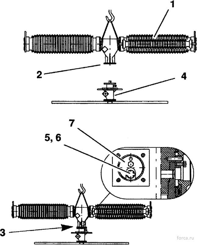
Рис.11-4. Установка дугогасительного устройства на сборочное приспособление.
- — дугогасительное устройство;
- — транспортная крышка с уплотнительным кольцом;
- — болты М 12×80, 4 шт.; шайбы 13x28x3, 8 шт.; гайки М12, 4 шт.;
- — сборочное приспособление No. 1HSB 630030-R;
- — ось;
- — стопорное кольцо;
- — блок-шайба.

Рис.11 -5. Разборка дугогасительного устройства.
- — крышка;
- — контейнер с адсорбентом;
- — верхний токопровод;
- — корпус верхнего механизма;
- — изолятор;
- — поршень;
- — нижний токопровод;
- — вал с головкой под ключ 24 мм;
- — ось.

Рис.11-6. Замена верхнего токопровода.
- — фланец;
- — болт М8х20, пружинная шайба, шайба (по 12 шт.);
- — верхний токопровод;
- — дугогасительный контакт.
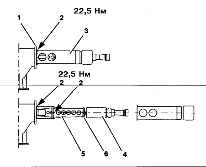
Рис.11-7. Замена нижнего токопровода.
- — корпус верхнего механизма;
- — болт М8х20, пружинная шайба, шайба 8.4x18x2 (по 12 шт.);
- — токоведущая труба;
- — поршень;
- — направляющая поршня;
- — фторопластовая полоса.
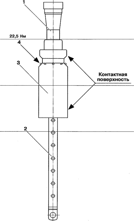
Рис.11-8. Замена поршня.
- — сопло;
- — тяга;
- — поршневой цилиндр;
- — болт М8х16, 8 шт; шайба 8.4x16x1.6, 8 шт.

Рис.11-9. Верхний механизм.
- — тяга (верхняя часть);
- — удерживающее кольцо;
- — уплотнительное кольцо;
- — втулка;
- — уплотнительное кольцо.
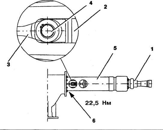
Рис.11-10. Установка поршня и нижнего токопровода.
- — поршень;
- — тяга;
- — соединительное звено;
- — ось;
- — нижний токопровод;
- — болты М8х20, 12 шт.; шайбы 8.4x20x2, 12 шт.; пружинные шайбы, 12 шт.
Рис.11-11. Сборка дугогасительного устройства.
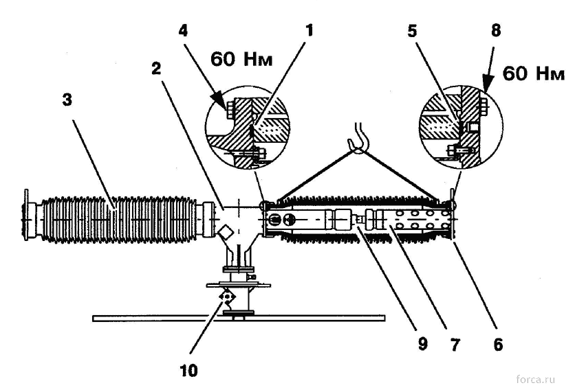
- — уплотнительное кольцо;
- — корпус верхнего механизма;
- — изолятор;
- — болты М12х50, 8 шт.; шайбы 13x28x3, 8 шт.;
- — уплотнительное кольцо;
- — верхний фланец;
- — верхний токопровод;
- — болты М 12×50, 8 шт.; шайбы 13x28x3, 8 шт.;
- — поршень;
- — ключ.

Рис.11-12. Установка контейнера с адсорбентом и крышки.
- — верхний фланец;
- — уплотнительное кольцо;
- — контейнер с адсорбентом;
- — верхняя крышка;
- — крышка;
- — ключ.
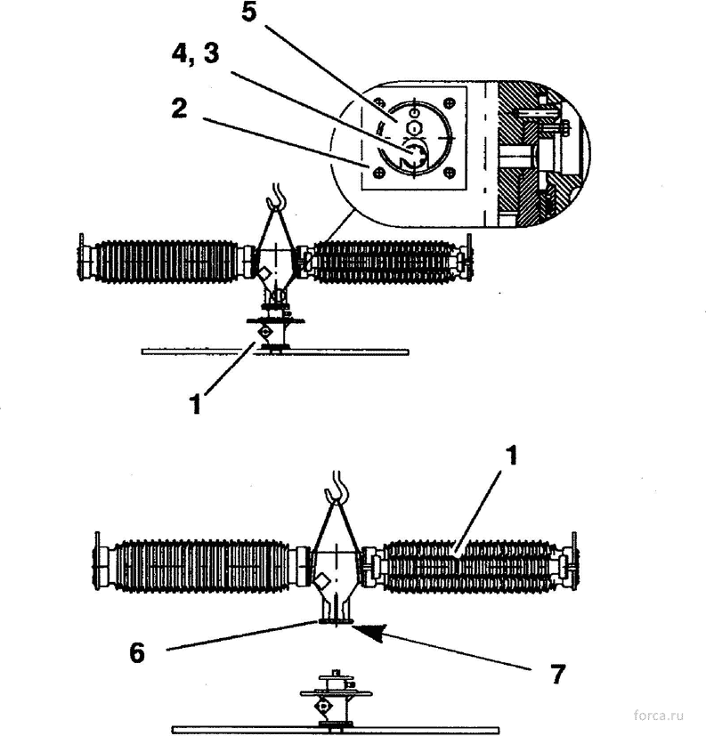
Рис.11-13. Установка блок-шайбы.
- — ключ;
- — крышка;
- — стопорное кольцо;
- — ось;
- — блок-шайба;
- — транспортная крышка с уплотнительным кольцом;
- — болты М12х50, 4 шт.; шайбы 13x28x3, 8 шт; гайки М12, 4 шт.
Рис.11-14. Демонтаж опорной изоляции.
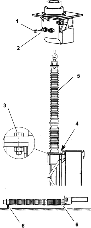
- — колпачок;
- — обратный клапан;
- — болты М20х60, 4 шт.; гайки М20, 4 шт.; шайбы 21x37x3, 8 шт.;
- — болты М12х40, 4 шт.; гайки М12, 4 шт.; шайбы 13x24x2.5, 8 шт.;
- — изолятор;
- — распорки.
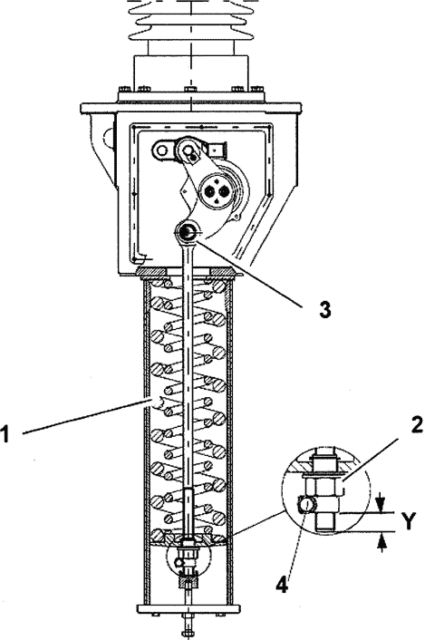
Рис.11-15. Разгрузка тяги.
- — отключающая пружина;
- — контргайка;
- — ось;
- — гайка хомута.

Рис.11-16. Разборка опорной изоляции.
- — транспортная крышка;
- — верхняя направляющая;
- — болты М 12×40, 4 шт.; шайбы 13x28x3;
- — верхний опорный изолятор;
- — болты М16х70, 8 шт.; шайбы 17x30x3, 16 шт.; гайки М16, 8 шт.;
- — кольцо с уплотнениями;
- — нижний опорный изолятор;
- — болты М 16×50, 8 шт.; шайбы 17x30x3, 8 шт;
- — оперативная тяга.
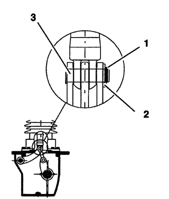
Рис.11-17. Демонтаж оперативной тяги.

Подшипники и уплотнительные кольца.
- — корпус механизма;
- — вал;
- — рычаг;
- — шариковый подшипник;
- — запорное кольцо;
- — втулка;
- — уплотнение 69.2 х 5.7;
- — уплотнительное кольцо 89.1 х 5.7;
- — шариковый подшипник.

Рис.11-19. Установка оперативной тяги.
- — рычаг;
- — серьга;
- — оперативная тяга;
- — ось;
- — шайба;
- — запорное кольцо;
- — нижний опорный изолятор;
- — болты М16 х 50, 8 шт.; шайбы 17 х 30 х 3, 8 шт.;
- — корпус механизма.

Рис.11-20. Сборка опорной изоляции.
- — кольцо с уплотнениями;
- — нижний опорный изолятор;
- — верхний опорный изолятор;
- — болты М16 х 70, 8 шт.; шайбы 17 х 30 х 3, 16 шт.; гайки М16, 8 шт.;
- — верхняя направляющая;
- — болты М12 х 40, 4 шт.; шайбы 13 х 28 х 3, 4 шт.;
- — транспортная крышка.
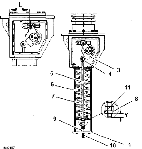
Рис.11-21. Регулировка отключающего механизма.
- — нижняя крышка;
- — болты М 10×50, 4 шт.;
- — рычаг;
- — ось;
- — тяга;
- — корпус;
- — отключающая пружина;
- — контргайка;
- — приспособление 1HSB446381-A;
- — регулировочный винт;
- — гайка хомута.

Рис.11-22. Панель управления привода.
- — панель;
- — ключ «включить/отключить»;
- — переключатель управления «местное/дистанционное»;
- — электрический счетчик;
- — индикатор состояния пружины.
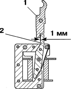
Рис.11-23. Проверка зазора.
- — вспомогательная защелка;
- — ярмо электромагнита.
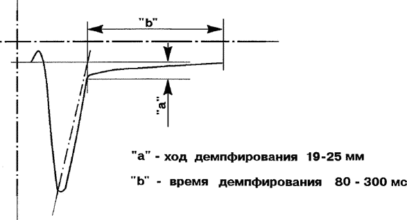
Рис.11-24. Демпфирование выключателя при включении.

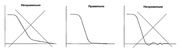
Рис.11-25. Демпфирование выключателя при отключении.
t1 — время, пропорциональное скорости контактов при отключении; t2 — время, определяемое демпфированием движения контактов; t3 — время, пропорциональное скорости контактов при включении.
Рис.11-26. Измерение времен срабатывания.
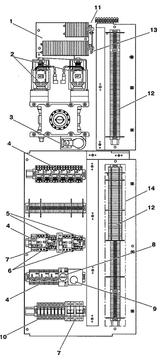
Рис.11-27. Клеммные сборки и другое электрооборудование.
- — два концевых выключателя со вспомогательными контактами;
- — двигатели;
- — переключатель управления “ручное/двигательное”;
- — реле;
- — контакторы;
- — автоматы;
- — выключатели;
- — розетка;
- — термостат;
- — предохранители;
- — отключающая катушка;
- — клеммный блок;
- — включающая катушка;
- — крышка.
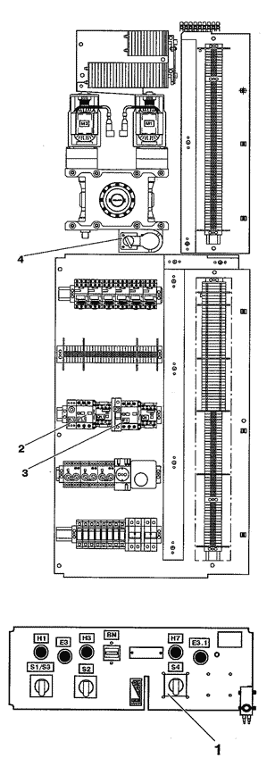
Рис.11-28. Расположение переключателей на панели управления.
- — переключатель управления «местное/дистанционное»;
- — автомат;
- — автомат;
- — переключатель управления «ручное/двигательное».

Рис.11-29. Разряд включающих пружин.
- — рукоятка;
- — кнопка реверсивной защелки;
- — переключатель управления «ручное/двигательное».

Рис.11-30. Установка блокирующих колодок.
- — блокирующая колодка, 2 шт.;
- — болт М8х60, 2 шт.

Рис.11-31. Снятие блокировки при медленном включении.
1 — оперативный стержень; 3 — блокирующая ось;
2 — блокирующая планка; 4 — отверстие для блокирующей оси

Рис.11-32. Операция медленного включения.
- — включающая катушка;
- — кулачковый диск;
- — стопорный ролик;
- — оперативный рычаг;
- — блокирующий язычок;
- — ролик;
- — блокирующий язычок;
- — ролик.

Рис.11-33. Снятие блокировки при медленном отключении.
1 — блокирующая планка; 4 — блокирующий диск;
2 — блокирующая ось; 5 — оперативный стержень.
3 — отверстие для блокирующей оси;

Рис.11-34. Операция медленного отключения.
- — включающая катушка;
- — блокирующий язычок;
- — ролик;
- — кулачковый диск;
- — стопорный ролик;
- — якорь;
- — оперативный рычаг.

Рис.11-35. Проверка расстояния для включающих пружин.

Рис.11-36. Механическая блокировка.
1 — концевой выключатель; 4 — кулачковый диск;
2 — блокирующая планка; 5 — оперативная тяга.
3 — блокирующий диск;

Рис.11-37. Снятие блокировки.
Источник
Note for Owners:
Guidesimo.com webproject is not a service center of ABB trademark and does not carries out works for diagnosis and repair of faulty ABB SF6 LTB 245E1 BLG 1002A equipment. For quality services, please contact an official service center of ABB company. On our website you can read and download documentation for your ABB SF6 LTB 245E1 BLG 1002A device for free and familiarize yourself with the technical specifications of device.
More Circuit breakers Devices:
-
Eaton Series NRX
Effective 10/08 For more information visit: www.eaton.com/seriesnrx 1IL01301016E(1) Only qualified electrical per-sonnel should be permitted towork on the equipment.(2) Always de-energize primaryand secondary circuits whenperforming these procedures.(3) Drawout circuit breakersshould should be levered(racked) out to the Disconnectposition.(4) All circuit breakers should beswitched to the off posit …
Series NRX Adapter, 4
-
Rittal NH1
1NH1-3 — MessmodulMontageanleitungDie Bedienungsanleitung und die CE-Konfor-mitätserklärung stehen als Download auf derHomepage von www.rittal.de zur Verfügung.FunktionsbeschreibungDas NH-Messmodul ist ein Zubehörprodukt fürRittal NH-Sicherungslasttrenner zum Messen,Erfassen und Auswerten elektrischerLeistungsdaten.Bestimmungsgemäße Verwendung, vorher-sehbarer FehlgebrauchDas NH-Messmodul i …
NH1 Circuit breakers, 2
-
Siemens 3WN6
13WN6Betriebsanleitung/Operating Instructions Bestell-Nr./Order No.: 3ZX1812-0WX36-4CA0 / 9239 9780 422Abschließvorrichtung gegen Einschalten 3WX3668-1J.00für FesteinbauschalterLocking device against closing for fixed-mounted circuit-breakersVerrouillage de fermeture pour disjoncteur fixeDispositivo de cierre contra conexiones para interruptor fijoDispositivo di blocco di chiusura per interrutto …
3WN6 Circuit breakers, 16
-
CHINT AX-5
NO:2020.04IEC 60947-5-1AX-5Mounting Instructions PaigaldusjuhisedИInstrukcja montażuMontageanleitungИнструкция по монтажуInstructions de montageAsennus-ja käyttöohjeetInstruções de montagemMonteringsveiledningMontážní návodIstruzioni di montaggioнструкции за монтажInstrucciones de montajeЩодо монтуванняMontaj TalimatlarıΟδηγίες Ε …
AX-5 Circuit breakers, 6
-
Eaton Bussmann Series
Bussmann series BSPD Type 1 and Type 2 surge protective devices for switchgear and power distribution panelsTable of Contents1.0 Introduction2.0 Installation3.0 Operating features4.0 Troubleshooting5.0 Specifications6.0 Catalog number system7.0 WarrantyInstruction Sheet IS10207 Rev 3Effective July, 2015Supersedes July 2014BUSSMANNSERI ES …
Bussmann Series Power distribution unit, 12
Recommended Documentation:
- Элегазовые выключатели типов HPL 72.5B1, HPL 420ТВ2, HPL 550ТВ2, HPL 800ТВ4, изготавливаемые в соответствии со стандартами МЭК 62271-100(2012) «Высоковольтное комплектное распределительное устройство. Часть 100. Высоковоль, ABB AB HIGH VOLTAGE PRODUCTS (ШВЕЦИЯ)
- Элегазовые выключатели типов HPL 72.5B1, HPL 420ТВ2, HPL 550ТВ2, HPL 800ТВ4, изготавливаемые в соответствии со стандартами МЭК 62271-100(2012) «Высоковольтное комплектное распределительное устройство. Часть 100. Высоковоль, ABB AB HIGH VOLTAGE PRODUCTS (ШВЕЦИЯ)
- Элегазовые выключатели-разъединители типа DCB LTB 145D1/B (для применения в сети 110кВ), Iном. до 3150А, Io.ном до 40кА ABB AB, HIGH VOLTAGE PRODUCTS (ШВЕЦИЯ)
При оптовых закупках необходимо правильно выбрать производство в Sweden, где с одной стороны цена ниже, но с другой стороны вы можете сэкономить на доставке. напрямую до Москвы, Казани или Санкт-Петербурга.
Мы можем помочь вам стать официальным дистрибьютером Элегазового выключателя
Пружины отключения составляют часть кинематической системы исполнительных механизмов выключателя и размещаются под корпусом механизма. При этом механическая энергия, необходимая для выполнения основной операции отключения, запасена в пружинах отключения все время, пока выключатель находится во включенном положении. Другими словами, включенный выключатель всегда готов к немедленному отключению.
Универсальные электродвигатели вращают редуктор взвода пружины и через него автоматически взводят пружины отключения сразу после выполнения каждой операции включения. Пружины удерживаются во взведенном состоянии защелкой, которая освобождается, когда выполняется операция включения выключателя. Это обеспечивает быстрое обратное включение выключателя по истечении времени бездействия 0,3 сек.
Принцип действия привода можно кратко описать следующим образом. Диск с кулачком и система пружин связаны друг с другом кольцевой цепью. Цепь, имеющая две ветви, охватывает звездочку на валу электродвигателя, передает энергию для взвода пружин, а также вращает диск с кулачком при выполнении операции включения выключателя.
Во время этого вращения диск с кулачком приводит в движение передаточный механизм, преобразующий вращательное движение в поступательное.
Демпфирующее устройство замедляет движение контактов в конечном положении.
Вспомогательное оборудование имеет следующие характеристики:
• износостойкие вспомогательные контакты и конечные выключатели;
• механический указатель состояния взвода, частичного взвода или отсутствия взвода пружины включения;
• весь электромонтаж для подключения внешних соединений выведен на клеммные колодки.
Одинаковое время срабатывания при любых условиях окружающей среды делает выключатель весьма удобным для управляемой коммутации.
Оценка статьи:

Загрузка…