
PSP SERIES
USER MANUAL
i
CONTENTS PAGE
1. Product Introduction……………………………………………………
1
2.
Safety Information……………………….……………….…… 3
3. Technical Specification………….…………………………….. 7
4.
Panel Controls and Indicator………………………….…..…. 9
5. Functional Description of Operation Element……………….. 12
6. Operating Instruction with Keypad Input…………………………. 13
7. Disposal………………………………………………………….. 17
8. Rectification of Faults………….……………………………… 18
9. Maintenance……….……….……………………………………. 19
10. APPENDIX: Connecting the Programmable Power Supply
via RS232 Interface…………………………………………………………… 21
PSP SERIES
USER MANUAL
ii
Declaration of Conformity
We
GOOD WILL INSTRUMENT CO., LTD.
No. 7-1, Jhongsing Rd., Tucheng City, Taipei County 236, Taiwan.
declares that the below mentioned product
PSP-603, PSP-405, PSP-2010
Are herewith confirmed to comply with the requirements set out in the Council
Directive on the Approximation of the Law of Member States relating to
Electromagnetic Compatibility (89/336/EEC, 92/31/EEC, 93/68/EEC) and Low
Voltage Equipment Directive (73/23/EEC, 93/68/EEC). For the evaluation regarding
the Electromagnetic Compatibility and Low Voltage Equipment Directive, the
following standards were applied:
◎ EMC
EN 61326-1:
Electrical equipment for measurement, control and laboratory use ––
EMC requirements (1997+A1: 1998)
Conducted and Radiated Emissions
EN 55011: 1998
Electrostatic Discharge
EN 61000-4-2: 1995+A1:1998
Current Harmonic
EN 61000-3-2: 1995+A1: 1998+A2: 1998
Radiated Immunity
EN 61000-4-3: 1996
Voltage Fluctuation
EN 61000-3-3: 1995
Electrical Fast Transients
EN 61000-4-4: 1995
————————-
Surge Immunity
EN 61000-4-5: 1995
————————-
Conducted Susceptibility
EN 61000-4-6: 1996
————————-
P.F.Magnetic Field
EN 61000-4-8: 1993
————————-
Voltage Dips/ Interrupts
EN 61000-4-11: 1994
◎ Safety
Low Voltage Equipment Directive 73/23/EEC & amended by 93/68/EEC
IEC/EN 61010-1: 2001
EN 60950 :1992+A1:1993+A2 :1993+A3 :1995+A4 : 1997+A11: 1997
IEC 60950:1991+A1:1992+A2 :1993+A3 :1995+A4 : 1996
* Изображения служат только для ознакомления,
см. техническую документацию
6 000 руб.
× 1 =
6 000 руб.
Добавить в корзину 1 шт.
на сумму 34 100 руб.
Посмотреть альтернативные предложения1
Номенклатурный номер: 849526540
Артикул: PSP-405
Страна происхождения: ТАЙВАНЬ (КИТАЙ)
Бренд / Производитель: GW Instek
Описание
0-40 В 5А , Дискретность 10мВ/2мА, Защита от перегрузок,перенапряжения,перегрева, Блокировка клавиш, Высокий КПД, Интерфейс RS232, масса 4 кг
Технические параметры
| Госреестр РФ | есть |
| Выходное напряжение, В | 40 |
| Выходной ток, А | 5 |
| Тип источника | импульсный |
| Вес, кг | 4.39 |
Техническая документация
-
Contents
-
Table of Contents
-
Bookmarks
Quick Links
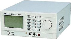
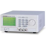
Programmable Power Supply
PSP-603, PSP-405, PSP-2010
USER MANUAL
ISO-9001 CERTIFIED MANUFACTURER
Related Manuals for GW Instek PSP-603
Summary of Contents for GW Instek PSP-603
-
Page 1
Programmable Power Supply PSP-603, PSP-405, PSP-2010 USER MANUAL ISO-9001 CERTIFIED MANUFACTURER… -
Page 3: Table Of Contents
Table of Contents Table of Contents SAFETY INSTRUCTIONS ……….2 GETTING STARTED …………7 Main Features ……..8 Accessories ……….8 PSP Series Lineup ……..9 Front Panel Overview ……10 Display Overview ……… 12 Rear Panel Overview ……14 Set Up ……….
-
Page 4: Safety Instructions
PSP Series User Manual AFETY INSTRUCTIONS This chapter contains important safety instructions that you must follow when operating a PSP series power supply and when keeping it in storage. Read the following before any operation to insure your safety and to keep the instrument in the best possible condition.
-
Page 5: Safety Guidelines
SAFETY INSTRUCTIONS Safety Guidelines Do not place any heavy object on the power General supply. Guideline Avoid severe impact or rough handling that CAUTION could lead to damaging the power supply. Do not discharge static electricity to the power …
-
Page 6
PSP Series User Manual For fire prevention, replace the fuse only with the specified type and rating. Disconnect the power cord before fuse replacement. Make sure the cause of the fuse blowout is fixed before replacing the fuse. Disconnect the power cord before cleaning. -
Page 7
SAFETY INSTRUCTIONS Location: Indoor Storage environment Relative Humidity: < 80% Temperature: −10°C to 70°C All electronically conducting materials (cables, General leads, terminals) must be sufficiently insulated. Precautions Connected loads should not be left CAUTION unsupervised. Ensure adequate ventilation for operation. -
Page 8
PSP Series User Manual Power cord for the United Kingdom When using the power supply in the United Kingdom, make sure the power cord meets the following safety instructions. NOTE: This lead/appliance must only be wired by competent persons WARNING: THIS APPLIANCE MUST BE EARTHED IMPORTANT: The wires in this lead are coloured in accordance with the following code: Green/ Yellow:… -
Page 9: Getting Started
GETTING STARTED ETTING STARTED This chapter describes the main features, front / rear panel appearance, and how to set the power supply connection. Main Features ……….. 8 Accessories …………8 PSP Series Lineup ……….9 Front Panel Overview ……..10 Display Overview ……….
-
Page 10: Main Features
PSP Series User Manual Main Features 200 watt output Performance 0~60V/0~3.5A (PSP-606) 0~40V/0~5A (PSP-405) 0~20V/0~10A (PSP-2010) High resolution and accuracy Current, power and voltage limits. Operation Current limiter for short circuit and overload protection Key lock …
-
Page 11: Psp Series Lineup
The PSP Series are single output programmable switching DC power supplies. There are 3 models in the PSP series lineup. For detailed information, please see the specification table on page 58. Model Power Voltage Current PSP-603 200W 0~60V 0~3.5A PSP-405 200W 0~40V…
-
Page 12: Front Panel Overview
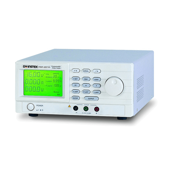
PSP Series User Manual Front Panel Overview + % Key NORMAL Key — % Key LCD Display CF Key V set Key REM Key N Key F Key Scroll Wheel + Output Terminal Power Switch — Output Terminal Ground Terminal V Limit Key Enter Key P Limit Key Output Key I Limit Key…
-
Page 13
GETTING STARTED Sets the scroll wheel to Normal (coarse) N key mode. Sets the negative percentage offset value -% key or decreases the voltage output by the negative percentage offset. Locks the scroll wheel and panel keys. LOCK LOCK Sets the scroll to Fine mode. F key Adjustments measurement Scroll Wheel… -
Page 14: Display Overview
PSP Series User Manual Display Overview Fine adjustment Current Limit indicator indicator limit Current Adjustment Voltage limit Voltage Voltage indicator indicator limit L I M I T S f i n e V — c o n s t I — c o n s t P — c o n s t O v e r t e m p O u t p u t…
-
Page 15
GETTING STARTED When the temperature exceeds the internal Over temperature temperature limit, the Over temperature indicator indicator is displayed. Front panel key lock. Panel Lock Remote is displayed when in remote control mode. Remote Displays the power output. Power… -
Page 16: Rear Panel Overview
PSP Series User Manual Rear Panel Overview Power Socket Voltage selector switch Cooling fan RS232 Fuse The power socket accepts AC Power Socket/Fuse mains voltage, 115V or 230V. Fuse: T3.15A/250V (230V input), T6.3A/250V (115V input) Sets the mains input voltage. Left, Voltage Selector 230V, right, 115V.
-
Page 17: Set Up
GETTING STARTED Set Up Power up 1. Set the rear panel Panel operation 115V 230V Voltage selector to the correct position according to the AC mains voltage. 2. Connect the power cord to the socket. 3. Turn On the power switch.
-
Page 18
PSP Series User Manual Ensure the output is off when connecting any cables Warning to the power supply. Inspect all cables or wires for damage before use. Any exposed wiring from cables can be extremely hazardous. If a cable is deemed hazardous, replace before use. -
Page 19: Operation
OPERATION PERATION The operation chapter describes how to set the limits, output voltage and how to adjust configuration settings. Voltage Limit Settings ……….18 Current Limit Settings ……….19 Power Limit Settings……….. 20 Voltage Output Setting ……….21 Output …………….. 22 Percentage Offset Output ……….
-
Page 20: Voltage Limit Settings
PSP Series User Manual Voltage Limit Settings The voltage limit settings determine the maximum voltage output for the power supply. 1. Press the V LIMIT key. The U-const Panel operation V LIMIT icon will flash. 2. Use the scroll wheel to adjust the voltage limit in the U-const field.
-
Page 21: Current Limit Settings
OPERATION Current Limit Settings The current limit settings determine the maximum current output for the power supply. 1. Press the I LIMIT key. The I-const Panel operation I LIMIT icon will flash. 2. Use the scroll wheel to adjust the current limit in the I-const field.
-
Page 22: Power Limit Settings
PSP Series User Manual Power Limit Settings The power limit settings determine the maximum power output for the power supply. 1. Press the P LIMIT key. The P-const Panel operation P LIMIT icon will flash. 2. Use the scroll wheel to adjust the current limit in the P-const field.
-
Page 23: Voltage Output Setting
OPERATION Voltage Output Setting The voltage output can be changed at any time when the panel is not locked. The voltage output is limited by the voltage limit value (U-const). The voltage output can be edited regardless of whether the output is on or off. 1.
-
Page 24: Output
PSP Series User Manual Output The output can be turned on or off via the OUTPUT key. The power supply’s output is off by default. The voltage output level can be changed regardless of whether the output is on or off. 1.
-
Page 25: Percentage Offset Settings
OPERATION Percentage Offset Settings The power supply output can be increased or decreased by a set percentage. For example, if the voltage output is 10V, and the +% value is 110, then the voltage will increased to 110%, making the final voltage 11V. 1.
-
Page 26: Scroll Wheel Step Resolution
PSP Series User Manual Scroll Wheel Step Resolution The Step resolution of the scroll wheel can be adjusted by fine or coarse steps. Fine and Normal (Coarse) mode is applicable to limit and voltage output settings. 1. Press the F key to select fine mode. Fine Mode 2.
-
Page 27: Remote Panel Lock
OPERATION 2. When the panel is locked, locked will be displayed at the bottom of the display. L I M I T S f i n e U — c o n s t I — c o n s t P — c o n s t O u t p u t l o c k e d…
-
Page 28: Remote Control
PSP Series User Manual EMOTE CONTROL This chapter describes how to configure the power supply and PC for RS-232C remote control (Please use GTL-232A cable only). Interface Configuration ……..28 Configure RS-232C interface ……..28 RS-232C Setup …………29 Command Syntax …………. 33 Command Set ……….
-
Page 29
REMOTE CONTROL D …………….48 Q …………….48 SB+ …………….49 SB- …………….49 SD+ …………….49 SD- …………….49 SV …………….50 SU …………….50 SI …………….50 SP …………….51 Setting for different command format ….. 52… -
Page 30: Interface Configuration
PSP Series User Manual Interface Configuration Configure RS-232C interface DB-9, Male RS-232C Connector configuration 2400 Baud rate None Parity Data bit Stop bit none Data flow control Connect the GTL-232A cable RS232 (custom RS-232C) to the rear panel port: DB-9 male connector.
-
Page 31: Rs-232C Setup
REMOTE CONTROL Because DTR is controlled by software, it needs to Note be set beforehand. Otherwise, it may cause that 12V can’t be output to PSP and no readback response. RS-232C Setup Background For remote control connection, the PSP power supply series uses a custom RS-232C connection with a propriety pin out configuration.
-
Page 32
PSP Series User Manual 3. Right click ASRL2: INSTR”COM2” The port number depends on which port you Note connected to PSP Power Supply. 4. Click the Open Visa Test Panel. Functionality Check 5. Click on the Configuration icon. 6. Select the Serial Settings tab. 7. -
Page 33
REMOTE CONTROL 9. Click on the Configuration icon. 10. Select the Flow Control Settings. 11. Click Apply Changes. 12. Click on the Configuration icon. 13. Select the I/O Settings tab. 14. Mark the Enable Termination Character checkbox. Make sure the termination character is a line feed (n, value: xA). -
Page 34
PSP Series User Manual 16. Click the Input/Output icon. 17. Enter “Lr” in the Select or Enter Command drop box. 18. Click on Query. 19. The information about xxx will be displayed in the buffer as below. -
Page 35: Command Syntax
REMOTE CONTROL Command Syntax Command types The power supply has 25 remote commands. Commands and queries can be written in either ASCII or hexadecimal. All ASCII commands are case sensitive. All parameters are format sensitive. 1: command header Command SV 10.00<CR> format 2: space 1 2 3…
-
Page 36
PSP Series User Manual Commands can be written in ASCII or Hexadecimal Hexadecimal. Below are examples of ASCII and hexadecimal commands. ASCII W< CR> 57 0D Each command must have a carriage return and Message terminators line feed character as a message terminator. All return messages are terminated with a carriage return and line feed terminator. -
Page 37: Command Set
REMOTE CONTROL Command Set Query The L query returns all the status values of the Description power supply. L<CR> ASCII Query Syntax 4C 0D Return Parameter Vvv.vvAa.aaaWwww.wUuuIi.iiPpppFf <CR><LF > Character Description Voltage unit vv.vv Voltage value (5 characters, 2 decimal places) Current Unit a.aaa…
-
Page 38
PSP Series User Manual Relay Status: 0: on, 1: off Temperature Status 0:normal, 1:overtemp Step mode: 0:coarse, 1:fine Scroll wheel status: 0:locked, 1:unlocked Remote Status: 0:normal, 1:remote Lock Status: 0:unlocked, 1:locked Returns the status Example L<CR> values of the power V20.00A2.500W050.0U40I5. -
Page 39
REMOTE CONTROL Query The V query returns the voltage output of the Description power supply. V<CR> ASCII Query Syntax 56 0D Return Parameter Vvv.vv<CR><LF> Character Description Voltage unit vv.vv Voltage value (5 characters, 2 decimal places) Returns the voltage output. Example V<CR>… -
Page 40
PSP Series User Manual Query The A query returns the current output of the Description power supply. A<CR> ASCII Query Syntax 41 0D Return Parameter Aa.aaa<CR><LF> Character Description Current unit a.aaa current value (5 characters, 3 decimal places) Returns the current output. Example A<CR>… -
Page 41
REMOTE CONTROL Query The U query returns the current voltage limit. Description U<CR> ASCII Query Syntax 55 0D Return Parameter Uuu<CR><LF> Character Description Voltage limit unit Voltage limit value (2 characters, no decimal) Returns the current voltage limit. Example U<CR> U10<CR><LF>… -
Page 42
PSP Series User Manual Query The P query returns the current power load limit. Description P<CR> ASCII Query Syntax 50 0D Return Parameter Pppp<CR><LF> Character Description Power load limit unit Power limit value (3 characters, no decimal) Returns the current load limit. Example P<CR>… -
Page 43
REMOTE CONTROL Query The F query returns the status of the power Description supply. F<CR> ASCII Query Syntax 46 0D Return Parameter F f <CR><LF> Status Byte character Relay Status: 0: off, 1: on Temperature Status 0:normal, 1:overtemp Step mode: 0: normal, 1:fine Scroll wheel status: 0:locked, 1:unlocked… -
Page 44
PSP Series User Manual Command The SV+ command increases the voltage output Description by 1V (coarse mode) or 1mV(fine mode). 20.00V21.00V (coarse mode) 20.00V20.01V (fine mode) SV+<CR> ASCII Syntax 53 56 2B 0D Increases the voltage output by Example SV+<CR> one unit. -
Page 45
REMOTE CONTROL Command The SU- command decreases the voltage limit by Description SU-<CR> ASCII Syntax 53 55 2D 0D Decreases the voltage limit by one Example SU-<CR> unit. Command The SI+ command increases the current limit by Description 10mA (coarse mode) or 1mA(fine mode). 3.01A3.11A (coarse mode) 3.01A3.02A (fine mode) SI+<CR>… -
Page 46: Sum
PSP Series User Manual Command The SP+ command increases the load limit by 1W. Description SP+<CR> ASCII Syntax 53 50 2B 0D Increases the load limit by one Example SP+<CR> unit. Command The SP- command decreases the load limit by 1W. Description SP-<CR>…
-
Page 47: Sim
REMOTE CONTROL Command The SIM command sets the current limit to the Description maximum rating. SIM<CR> ASCII Syntax 53 49 4D 0D The current limit is set to the Example SIM<CR> maximum rating. Command The SPM command sets the load limit to the Description maximum rating.
-
Page 48: Koe
PSP Series User Manual Command The KN command sets the step resolution to Description normal (coarse) mode. KN<CR> ASCII Syntax 4B 4E 0D The scroll wheel step resolution is Example KN<CR> set to normal (coarse). Command The KO command toggles the output On or Off. Description KO<CR>…
-
Page 49: Eep
REMOTE CONTROL Command The EEP command saves the settings to internal Description memory. The settings will recalled upon the next startup. EEP<CR> ASCII Syntax 45 45 50 0D Save settings to memory. Example EEP<CR> Query The B query returns the +% value. Description B<CR>…
-
Page 50
PSP Series User Manual Query The D query returns the -% value. Description D<CR> ASCII Query Syntax 44 0D Return Parameter Bbbb<CR><LF> Character Description -% unit Dddd -% value 50~100 (3 characters, no decimal) Returns the -%unit and value Example D<CR>… -
Page 51
REMOTE CONTROL Command The SB+ command increases the +% offset by 1%. Description SB+<CR> ASCII Syntax 53 42 2B 0D Increase the +% offset by 1 percent. Example SB+<CR> Command The SB- command decreases the +% offset by 1%. Description SB-<CR>… -
Page 52
PSP Series User Manual Command The SV command sets the voltage output level. Description SV <parameter> <CR> ASCII Syntax 53 56 <parameter> 0D Parameter <parameter> Description xx.xx Voltage value( 5 characters, 2 decimal places) Sets the voltage output to 10.5V. Example SV 10.50<CR>… -
Page 53
REMOTE CONTROL Command The SP command sets the power limit. When the Description power limit is changed the current limit will be automatically altered to suit. SP <parameter> <CR> ASCII Syntax 53 50<parameter> 0D Parameter <parameter> Description Power limit value( 3 characters, no decimal) Sets the power limit to 100W. -
Page 54: Setting For Different Command Format
PSP Series User Manual Setting for different command format UART setting can be used to deter if command Background format to be modified for the PSP with firmware V1.66 or above. Before setting, please make sure that the connection between a computer and the PSP is normal by entering “L”…
-
Page 55
REMOTE CONTROL 1. Set PSP1 with setting A (see note below), then Operation Enter “URPSP1”. The PSP’s response is shown in the diagram below and has beep sound. 2. Set PSP2 without A(see note below), then Enter “URPSP2”. The PSP’s response is shown in the diagram below and has beep sound. -
Page 56
PSP Series User Manual 0x0D 0x0D 0x0A as shown in the diagram below. When setting is without A, the terminator for responsed message on the display is 0x0D 0x0A as shown in the diagram below. On the other hand, you can judge if setting is with A by the readback voltage value. -
Page 57
REMOTE CONTROL Otherwise, it is setting without A as the diagram shown below. -
Page 58: Faq
PSP Series User Manual Q1. No Display. Ensure the power supply is turned on. Ensure the mains cable is properly inserted and power is on. Check the fuse assembly. Q2. The front panel keys are inactive. The panel lock or remote control is activated. See page 24, 25. …
-
Page 59: Appendix
APPENDIX PPENDIX Fuse Replacement 3. Take off the power cord and remove the fuse Step socket using a minus driver. 4. Replace the fuse in the holder. T3.15A/250V Rating…
-
Page 60: Fan
PSP Series User Manual The PSP has a temperature or load controlled fan. Cooling fan The fan will be activated when the temperature or current exceeds a set level (model specific). Model PSP-405 PSP-603 PSP-2010 45˚C±5˚C 45˚C±5˚C 45˚C±5˚C Fan On 2.10A±50mA 1.40±50mA…
-
Page 61: Specification
APPENDIX Specification Model PSP-603 PSP-405 PSP-2010 Operating voltage 115/230 VAC ±15% Power frequency 50/60 Hz Power consumption approx. 420VA max. Power output 200W max. Output voltage 0~60VDC 0~40VDC 0~20VDC 20mV resolution 10mV resolution 10mV resolution Program Accuracy ±0.05%±4 digits ±0.05%±3 digits ±0.05%±3 digits Output Current 0~3.5A…
-
Page 62
PSP Series User Manual Current ±0.1%±5 digits ±0.1%±5 digits ±0.3%±10 digits Digital Display Multi-line LCD with background lighting AC fuse Slow-blow T6.3A/250V for 115V, T3.15A/250V for 230V Weight Approx. 4 kg Dimensions Approx. 225×100×305 m/m (W × H × D) (excluding stand and power cable) Command 250ms… -
Page 63: Declaration Of Conformity
APPENDIX Declaration of Conformity GOOD WILL INSTRUMENT CO., LTD. Declare that the below mentioned product Model Number: PSP-405, PSP-603, PSP-2010 satisfies all technical relations application to the product within the scope of council: Directive: 2014/30/EU, 2014/35/EU, 2011/65/EU, 2012/19/EU The above product is in conformity with the following standards or other normative documents: ◎…
-
Page 64: Index
PSP Series User Manual NDEX Caution symbol ….2, 29 Operation ……… 17 Cleaning the instrument ..4 Output ……..22 Coarse mode ……24 panel keys Command faq ……….56 Percentage offset output ..22 format ……..33 parameter ……. 33 Percentage offset settings ..