-
Contents
-
Table of Contents
-
Bookmarks
Quick Links
目录 CONTENTS ………………………………………………………………………………………………………….. — 1 —
1. 产品规格(SPECIFCATIONS) …………………………………………………………………………… — 2 —
3.加油方法(LUBRICATION) ………………………………………………………………………………… — 3 —
第1章 产品接口 ………………………………………………………………………………………………………. — 12 —
1.1 接口插头连接 ……………………………………………………………………………………………… — 12 —
2.2 操作面板各按键功能说明 ……………………………………………………………………………. — 14 —
第3章 系统参数设置说明 ………………………………………………………………………………………… — 16 —
3.1 技术员参数表 ……………………………………………………………………………………………. — 16 —
3.2 系统员参数表 ……………………………………………………………………………………………. — 18 —
3.3 监控参数表 ……………………………………………………………………………………………….. — 19 —
3.4 故障代码表 ……………………………………………………………………………………………….. — 20 —
第4章 特殊功能操作说明 ………………………………………………………………………………………… — 23 —
4.1 上停针位调整 …………………………………………………………………………………………….. — 23 —
4.2 一键恢复机头厂家参数值 ………………………………………………………………………….. — 24 —
4.3 自动测试 …………………………………………………………………………………………………… — 24 —
零件样本 ………………………………………………………………………………………………………………….. — 25 —
目录 CONTENTS
— 1 —
Summary of Contents for Jack JK-T1377E
This manual is also suitable for:
Jk-t373e
3.1 The technician parameter table
1.Long press
, can modify the technician parameter table;
2.Press the corresponding key
parameter number and change the corresponding parameter values;
3.Finally to press the key , exit parameters setting mode, back to the
sewing pattern.
The serial
range
number
100
100
101
200
~
104
200
108
100
13A
0
800
~
13E
0
800
~
140
0
149
0
~
164
—
165
XXXX
Note: 16 x parameter operation is to be a long time holding down the key
about 3 to 5 seconds.
Typical
Parameters to describe
values
800
200
The sewing speed
~
The maximum speed limit on free
1500
1500
seam top speed (global)
800
400
Reset speed
~
800
400
Sewing speed slow
~
300
Pedal presser foot set the time
Presser foot lift the delay time
10
Electricity automatically find a
2
1
parking space: 0: don’t look for;
~
1: find a ;2:automatically find Used to
Presser foot slowly let go off (0
10
0
closed slowly, non-zero for slow
opening)
password
7001
Restore the factory Settings
and
or and
— 17 —
keys can choose
note
speed
Pedal
speed
paramet
er
set
Table of Contents for Jack JK-T1377E:
-
— 29 — 2、机壳部件/Arm & miscellaneous cover components 序号 零件件号 名称 数量 DESCRIPTION 1 4091206200 面板盖组件 1 FACE PLATE COMPL 2 H05002 GB/T896-1986 挡圈 3 1 E-RING 3.2 3 40927004 第三夹线弹簧 1 TENSION SPRING 4 40902003 夹线螺栓 1 NIPPER RELEASING STOP 5 40913002 第四线导向装置 1 THREAD GUIDE NO.4 6 403S11011 螺钉 1 SCREW 7 4091301400 3 号线张力器组件 1 THREAD TENSION NO.3 ASM.
-
— 22 — E r r — 1 1 The nose needle Signal failure Check whether the nose synchronous signal device and the connection to the controller is loose, it returned to normal after restart the system. If it still doesn’t work, please replace the controller and notify the manufacturer. E r r — 1 2 Motor fault initial Angle measure Please try again when the power is 2-3 times, if still at fault, please replace the controller and notify the manufacturer E r r — 1 3 Motor HALL fault Shut
-
— 15 — 2.2 Operation panel each key-press function description Theserial number appearance name Functional description 1 Confirm and Return key Key input parameters confirmed a key, and backs up one level menu until the sewing operator working condition. In addition, but also with other key press at the same time Implement composite function, can enter advanced
-
— 34 —
-
— 7 — 11.机针和弯针的关系(NEEDLE -TO-LOOPER RELATION) ★机针和弯针按照如下方法进行调整 (1)按转动方向驱动手轮,让针杆落到最下点,然后拧松固定螺丝(决定针杆高度) (2)TQx1机针时,使用上方的2条刻线,TQx7机针时,使用下方的2条刻线,把其中的上 刻线A对准针杆下端块的下端,然后拧紧固定螺丝。这时应让机针固定螺丝4进入到避 免与针杆下
-
— 6 — 9.线调节杆的调整(ADJUSTMENT OF THE THREAD PULL -OFF LEVER) To adjust the thread pull-off lever,insert a screwdriver through an opening in the machine arm side cover (left),loosen screw and adjust the position of nipper bar block (rear)to the left or the right . If the end of the thread is drawn from arrow hole
-
— 42 — 9
-
— 25 — 零件样本 (Parts Book)
-
— 14 — The index icon description The index icon description 1 Soft start function 4 Many pieces 2 Count/parameter values displayed 5 Free seam 3 After trimming the presser foot 6 Automatic test 2.2 操作面板各按键功能说明
-
— 3 — 2.机头安装方法(INSTALLATION OF MACHINE HEAD) 3.加油方法(LUBRICATION) (1)把No.1新机油加入到所指的孔处。(每周1~2次) (2)拧松安装螺钉,放倒缝纫机,把润滑脂加到螺旋齿轮和涡轮4上。 (3)每周检查一次机座安装台内的加油毛毡上面是否吸满油,不够时请加油。同时请往 曲轴部上也加油 (1�
-
— 16 — 第3章 系统参数设置说明 3.1 技术员参数表 注:16X 参数操作须长时间按住 键大约3-5 秒。 Chapter 3 system parameter setup instructions 参数编号 参数范围 典型值 参数描述 备注 100 100~800 200 起缝速度 速度 101 200~1500 1500 自由缝最高速(全局最高限速) 104 200~800 400 Reset速度,补针速度 108 100~800 400 慢速起缝速度 1
Questions, Opinions and Exploitation Impressions:
You can ask a question, express your opinion or share our experience of Jack JK-T1377E device using right now.

目录 CONTENTS
工业缝纫机伺服控制系统用户手册 …………………………………………………………………………….. — 2 —
1. 产品规格(SPECIFCATIONS) ……………………………………………………………………………. — 2 —
2.机头安装方法(INSTALLATION OF MACHINE HEAD) …………………………………….. — 3 —
3.加油方法(LUBRICATION) …………………………………………………………………………………. — 3 —
4.机针安装方法 (ATTACHING THE NEEDLE) …………………………………………………….. — 4 —
5.针杆罩的安装方法 (ATTACHING THE NEEDLE BAR GUARD) ……………………….. — 4 —
6.纽扣盘的安装方法(ATTACHING THE BUTTON TRAY ASSEMBLY) ………………. — 4 —
7.上线穿线方法(THREADING THE MACHINE )………………………………………………….. — 5 —
8.线张力(THREAD TENSION ADJUSTMENT) ……………………………………………………. — 5 —
9.线调节杆的调整(ADJUSTMENT OF THE THREAD PULL -OFF LEVER) ………… — 6 —
10.针导向器的位置(POSITION OF THE NEEDLE GUIDE ) …………………………………. — 6 —
11.机针和弯针的关系(NEEDLE -TO-LOOPER RELATION) ………………………………… — 6 —
12.爪扣装置的高度(HEIGHT OF THE BUTTON CLAMP) ……………………………………. — 7 —
13. 拨针器的调整(ADJUSTMENT OF THE NIPPER ) …………………………………………… — 8 —
14. 压脚压力的调节(WORK PRESSING FORCE ) ……………………………………………….. — 8 —
15. 压脚压力的调节(ADJUSTMENT OF THE BUTTON CLAMP STOP LEVER) … — 8 —
16. 松线同步时间的调整(TIMING OF THREAD TENSION RELEASE) ………………. — 9 —
17. 切线装置(AUTOMATIC THREAD TRIMMER) ……………………………………………. — 10 —
18. 电控部分(ELECTRIC CONTROL PART) ……………………………………………………. — 10 —
19.第1章 产品接口(CHAPTER 1 PRODUCT INTERFACE) …………………………………… — 12 —
1. 1 接口插头连接(INTERSACE PLUG CONNETTION) ………………………………….. — 12 —
1.2 接线与接地(WIRING AND GROUNDING) ……………………………………………….. — 13 —
20.第2 章 操作面板使用说明(CHAPTER 2 OPRATION PANEL INSTRUTIONS) …. — 13 —
2.1 操作面板的显示说明(THE OPRATION PANEL DISPLAY) ……………………… — 13 —
2.2 操作面板各按键功能说明(OPRATION PANEL KEY-PRESS FUNCTION) . — 14 —
22.第3章 系统参数设置说明(SYSTEM PARAMETER SETUP INSTRUCTION) …….. — 16 —
3.1 技术员参数表(THE TECHNICIAN PARAMETER TABLE) ……………………… — 16 —
3.2 系统员参数表(SYSTEM PARAMETER TABLE) …………………………………….. — 18 —
3.3 监控参数表(MONITORRING PARAMETER TABLE) ……………………………… — 18 —
3.4 故障代码表(THE FAULT CODE TABLE) ………………………………………………… — 19 —
23.第4章 特殊功能操作说明(SPECIAL FUNCTION INSTRUCTION) ……………………. — 22 —
4.1 上停针位调整(THE NEEDLE ON AN ADJUSTMENT) …………………………….. — 22 —
4.2 一键恢复机头厂家参数值(A KEY PARAMETER VALUES) ……………………… — 22 —
4.3 自动测试(AUTOMATIAC TEST ) ……………………………………………………………. — 23 —
24.零件样本(THE SAMPLE PARTS) ………………………………………………………………………. — 25 —
— 1 —
工业缝纫机伺服控制系统用户手册
前言
使用前请详细阅读本用户手册及所搭配的缝制设备说明书,配
!
注意
安全说明
· 在使用本产品之前,请先阅读《产品说明书》及所搭配的缝纫机机械说明书。
· 本产品必须由接受过专业培训的人员来安装或操作。
· 请尽量远离电弧焊接设备,以免产生的电磁波干扰本控制器而发生误动作。
· 请不要在室温45°以上或者0°以下的场所使用。
· 请不要在湿度30%以下或者95%以上或者有露水和酸雾的场所使用。
· 安装控制箱及其他部件时,请先关闭电源并拔掉电源插头。
· 为防止干扰或漏电事故,请做好接地工程,电源线的接地线必须以牢固的方式与大地有效连
接。
· 所有维修用的零部件,须由本公司提供或认可,方可使用。
· 在进行任何保养维修动作前,必须关闭电源并拔掉电源插头。控制箱里有高压危险,必须关闭
电源五分钟后方可打开控制箱。
合正确使用,并须由接受过专业培训的人员来安装或操作。
· 本手册中标有
符号之处为安全注意点,必须注意并严格遵守,以免造成不必要的损害。
1. 产品规格(SPECIFCATIONS)
控制器型号 AHE59
电源电压 AC 220±20% V
输出功率 550W
电机低速最大转矩 3Nm
电源频率 50HZ/60HZ
电机最大转速(r/min) 最高1500(常用1300~1400)
针数 8针、16针、32针(更改凸轮后可6、12、24针)
送布量 横向送布2.5~6.5mm 纵向送布0、2.5~6.5mm
纽扣尺寸 10~28mm
机针 TQ×1#16(#14~#18) TQ×7#16(#14~#20)
机油 NO.1新机油
The controller model
The power supply voltage
The output power
Low-speed maximum power frequency motor
Power frequency
Sewing speed 最高1500(常用1300~1400)
Number of stitches 8针、16针、32针(更改凸轮后可6、12、24针)
Feed amount 横向送布2.5~6.5mm 纵向送布0、2.5~6.5mm
Button size 10~28mm
Needle
Lubricating oil NO.1新机油
AC 220±20% V
AHE59
550W
3Nm
50HZ/60HZ
TQ×1#16(#14~#18) TQ×7#16(#14~#20)
— 2 —
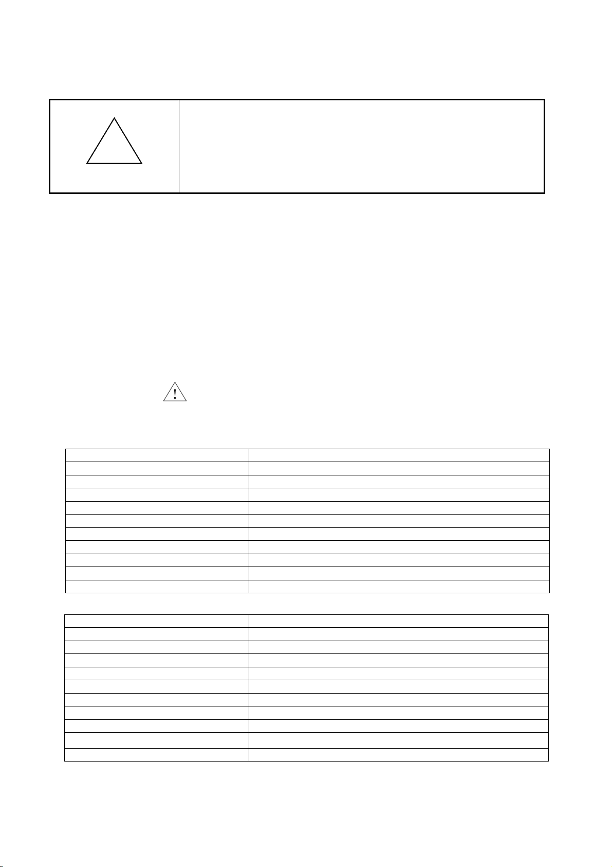
2.机头安装方法(INSTALLATION OF MACHINE HEAD)
脚踏
把防震橡胶垫放到台板上,然后把机头放在上面,用固定螺丝、垫片、螺母4固定好。
(Put rubber cushion on the table ,place the machine head on the rubber
cushion and fix it to the table using screws ,plain washersand nuts4.)
3.加油方法(LUBRICATION)
(1)把No.1新机油加入到所指的孔处。(每周1~2次)
(2)拧松安装螺钉,放倒缝纫机,把润滑脂加到螺旋齿轮和涡轮4上。
(3)每周检查一次机座安装台内的加油毛毡上面是否吸满油,不够时请加油。同时请往
曲轴部上也加油
(1)Apply New Dwfrix Oil No.1to the components shown by the arrows .
(once or twice a week)
(2)Loosen connecting screw ,tilt the head backward and apply some grease
to driving worm grease 4and gear .
( 3 ) Check , approximately once a week ,that oil amount is sufficient to
reach the top of the oil felt placed inside the bed mounting base .If the
amount of oil is insufficient, add an adequate amount of oil,At the time ,
also apply oil to crank rod.
— 3 —
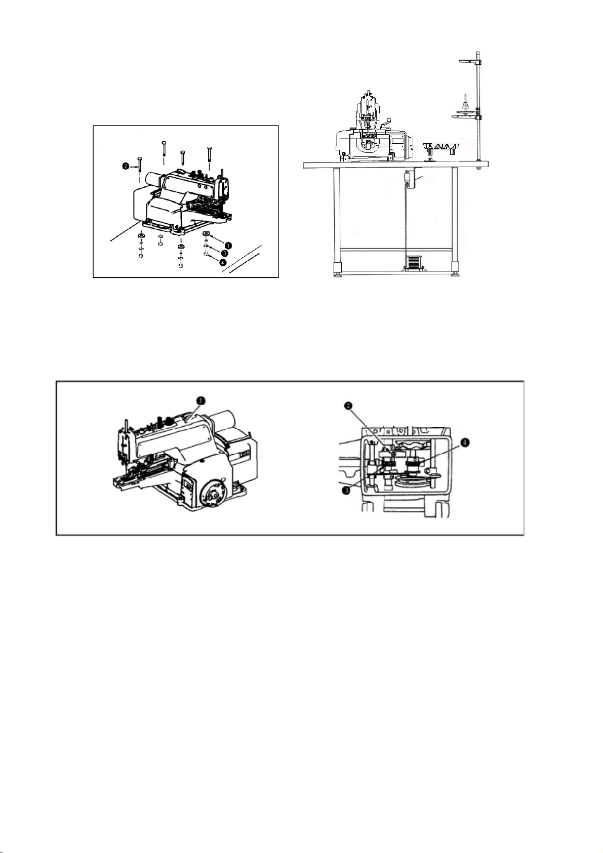
4.机针安装方法 (ATTACHING THE NEEDLE)
★标准机针为使用TQ×7#14
(1)拧松机针固定螺钉,手拿机针把机
针长沟转到面前。
(2)把机针插进针杆孔的深处。
(3)拧紧机针固定螺丝。
★Use a standard needle ofTQ×7#14
(1)Loosen sarew .
(2)Insert needle up into the
needle hole in the needle bar until
it comes in contact with the deepest
end of the needle hole.
5.针杆罩的安装方法 (ATTACHING THE NEEDLE BAR GUARD)
(1)拧松固定螺丝,并把它卸下。
(2)把针杆罩 安装到第二道线器的下
面。
(3)用固定螺丝固定起来。
(1)loosen screwand remone the
thread guide No.2.
(2)Place needle bar guard under
the thread guide No.2.
(3)Fix the thread guideNo.2 and
needle bar guard together using
screw.
6.纽扣盘的安装方法(ATTACHING THE BUTTON TRAY ASSEMBLY)
把纽扣盘插进机座前部的孔上,并把固
定螺丝拧紧固定。
Insert the posts of button tray
in the hole on the right of the
machine sub-base and tighten each
setscrew.
— 4 —
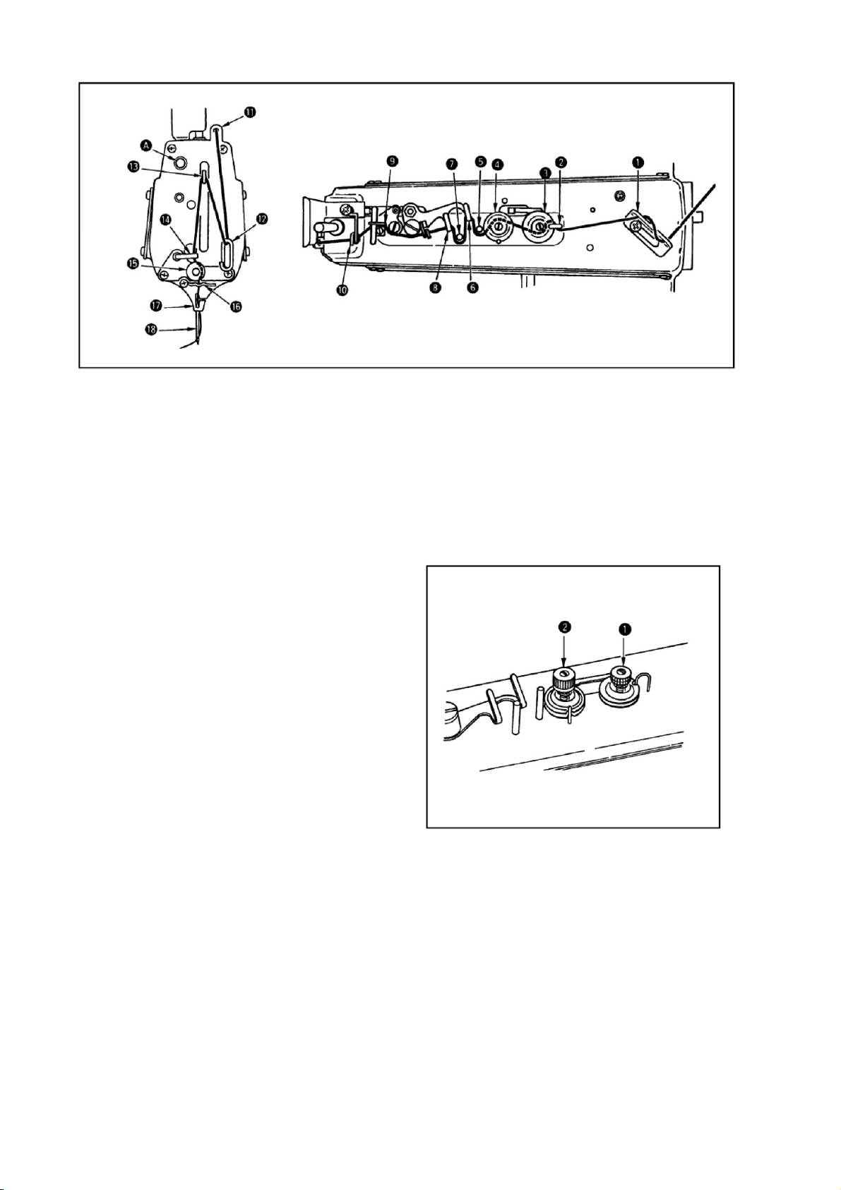
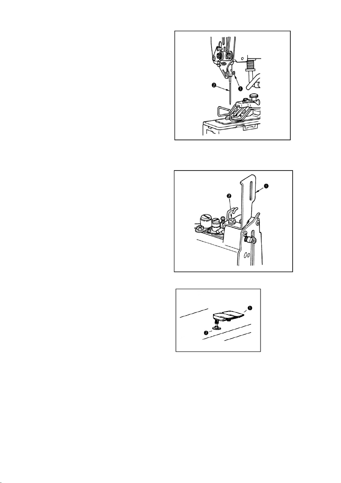
7.上线穿线方法(THREADING THE MACHINE )
如图所示的顺序进行穿线,从针孔的前侧向后侧按松线螺母A,把线拉出约60~70mm左
右。(Thread the machine in order of to18 as illustrated and pass the thread
through the needle eye from the front for 60 to 70 mm as you depress nipper
releasing knurted thumb nut A)
8.线张力(THREAD TENSION ADJUSTMENT)
第一线张力螺母是调整钉扣强度用
的,仅能调节极小的张力。
第二线张力调整螺母是调整背面的
紧线程度的,其张力比第一线张力螺母
强,根据使用的机线、布料、纽扣厚度等
情况,进行调整。
向右转动各线张力螺母之后,线张力变
强,向左转动则张力变弱。
Tension post No.1 is used to adjust the thread tension to sew on the
button and a relatively low tension will be enough. Tension post No.2
is used to adjust the thread tension applied to the root of the button
sewing stitches.
This tension must be determined according to the type of thread ,fabric
and thickness of the button and must be higher than that of tension post
No.1.turn the tension nuts clockwise to increase or counterclockwise
to reduce the thread tension .
— 5 —
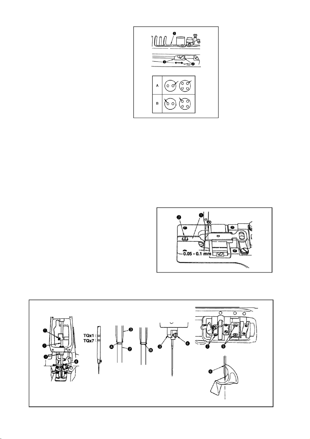
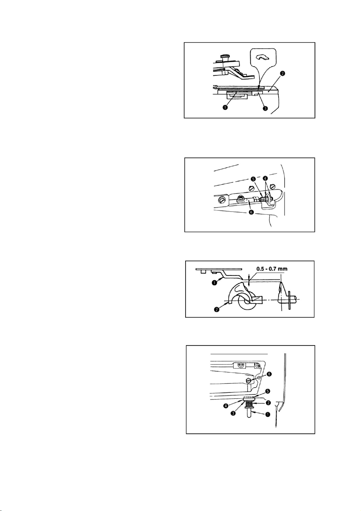
9.线调节杆的调整(ADJUSTMENT OF THE THREAD PULL -OFF LEVER)
调节线调节杆时时,请把螺
丝刀插进左侧面板上的孔中,拧松
固定螺丝,然后左右移动调节杆
的活动滑块 进行调整。缝制结
束,如果线头从A部前头的孔中露
出时,请把线调节杆活动滑块向
左移动,如果线头从B部箭头的孔
中露出时,请把滑块向右移动,不
让线头露出来。
To adjust the thread pull-off lever,insert a screwdriver through an opening
in the machine arm side cover (left),loosen screw and adjust the position
of nipper bar block (rear)to the left or the right . If the end of the
thread is drawn from arrow hole A in the button after sewing ,change the
position of nipper bar block (rear) to the left .Move the lever to the right
when the thread end comes out from arrow hole B .
10.针导向器的位置(POSITION OF THE NEEDLE GUIDE )
在针杆最下点,拧松螺丝,左右移动针
导向器,把机针和针导向器的间隙调
整为0.05~0.1mm
Loosen screw and provide a 0.05 to
0.1mm clearance between the needle
guide and the needle by moving
the needle guide to the left or
the right when the needle is in the
lowest position .
11.机针和弯针的关系(NEEDLE -TO-LOOPER RELATION)
— 6 —
★机针和弯针按照如下方法进行调整
(1)按转动方向驱动手轮,让针杆落到最下点,然后拧松固定螺丝(决定针杆高度)
(2)TQx1机针时,使用上方的2条刻线,TQx7机针时,使用下方的2条刻线,把其中的上
刻线A对准针杆下端块的下端,然后拧紧固定螺丝。这时应让机针固定螺丝4进入到避
免与针杆下端块相碰的沟槽里。(决定弯针的位置)
(3)拧松固定螺丝5,转动手轮,把针杆的2条一组的刻线中的下刻线B对准针杆下端块
的下端。
(4)在此状态,把弯针的针尖6对准机针的中心,然后拧紧固定螺丝5.
(5)拧松固定螺丝7,把弯针间隙调整为0.01~0.1mm,在拧紧螺丝7.
★ Adjust the needle-to-looper relation as follows :
(1 )Depress the pedal fully forward ,turn the needle driving pulley in the
normal sewing direction to bring down the needle bar to the lowest point of
its stroke and loosen screw
(Adjusting the needle bar height )
(2)Adjust the height of the needle bar using top two lines engraved on the
needle bar for the TQx1 needle and using the bottom two lines for the TQx7
needle .Align the upper line A with the bottom end face of needle bar bushing
(lower) and tighten screw in the way that needle clamp screw 4 rests in
the slot of the needle bar bushing (lower )
(3) Looper screws 5 and turn by hand the needle driving pully until lower
line B of two lines aligns with the bottom end face of needle bar bushing
(lower)
(4) By keeping the machine in this state ,align looper blade 6 with the
center of the needle and tighten screws 5
(5) Loosen screws 7 and provide a 0.01to 0.1 mm clearance between the
looper and the needle .tighten screws7.
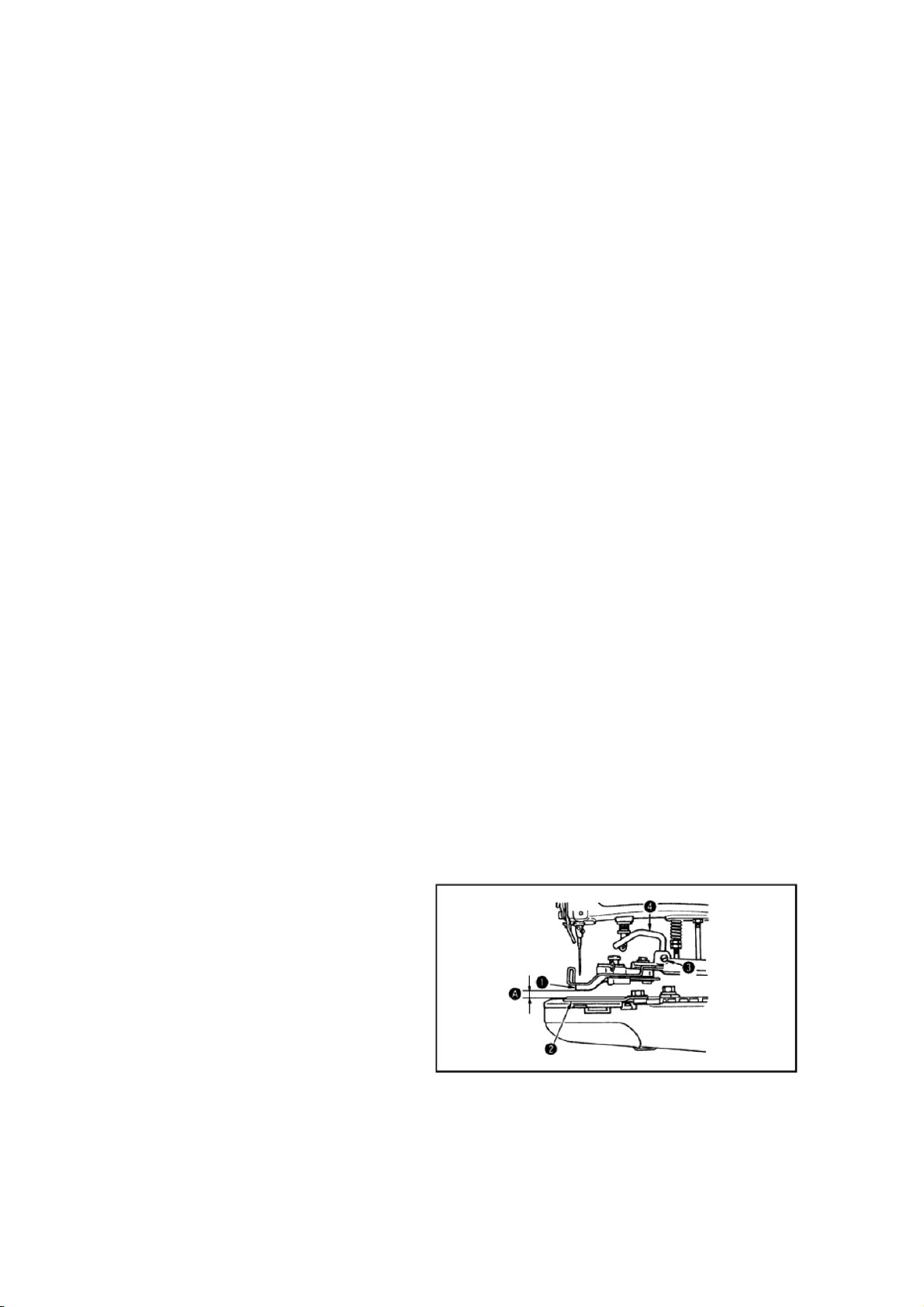
12.爪扣装置的高度(HEIGHT OF THE BUTTON CLAMP)
在断开位置,纽扣爪脚的地面和布
压脚下板上面的间隔A,1377E标准为
9mm。
The standard clearance A between the
bottom face of button clamp jaw lever
and the top face of feed plate is 9
mm for 1377E.Loosen screw and
adjust the height of button clamp
lfting hook4.
— 7 —
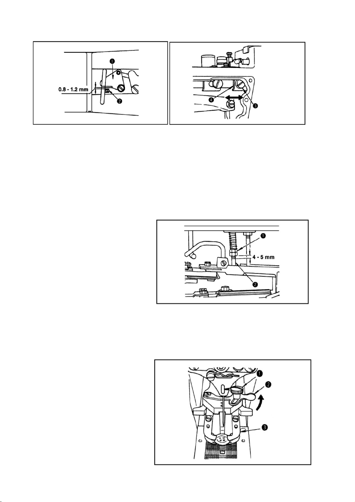
13. 拨针器的调整(ADJUSTMENT OF THE NIPPER )
运转时,把拔针器的方块和拔的间隙调整为0.8~1.2mm ,不让拔针器压住机线。调
节方法是,拧松固定螺钉,左右移动拔针器活动滑块4。
Provide a 0.8 to 1.2 mm clearance between nipper and nipper block to
prevent the nipper from nipping the thread while stitching .Loosen screw
and move nipper bar block 4 to the left or the right .
14. 压脚压力的调节(WORK PRESSING FORCE )
压脚的压力,以在转动螺母2个螺
母的下端和压脚压力调节杆的螺
丝部间隙为4-5mm时为准。
The standard work pressing force is
obtained by providing a 4 to 5 mm
clearance between the bottom face
of nut and the bottom end of the
screw of pressure adjusting bar.
15. 压脚压力的调节(ADJUSTMENT OF THE BUTTON CLAMP STOP LEVER)
在断开状态,拧紧固定螺丝,用
爪脚打开拔杆开关打开爪脚 ,
把纽扣设定到正确的位置。让纽扣
容易放进取出,然后拧紧螺丝。
Set the machine for stop -motion
state ,loosen clamp screw place a
button correctly in the sewing
position and adjust button clamp
stop lever to permit the button
properly to rest on button clamp
jaw levers .tighten clamp screw
after determining the distance
between the left and right jaw
levers
— 8 —
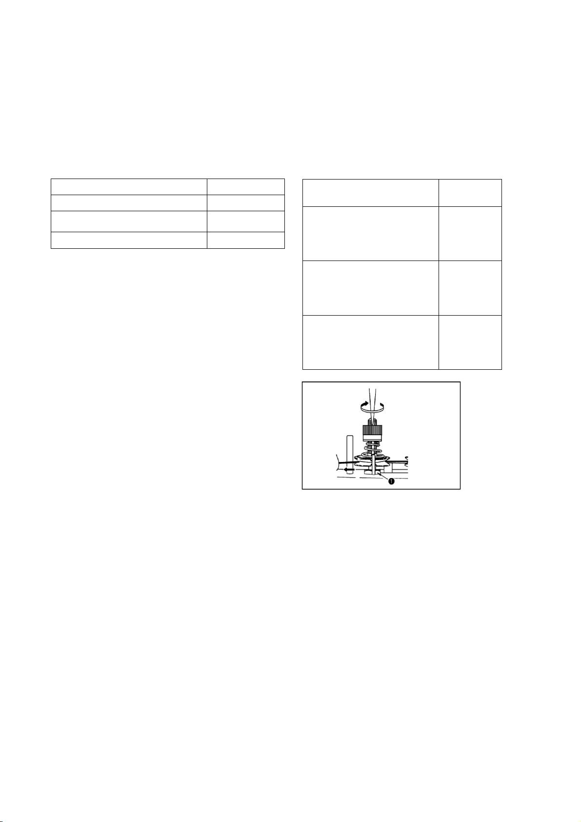
16. 松线同步时间的调整(TIMING OF THREAD TENSION RELEASE)
沿箭头方向拉机线,转动手轮,有一个第二线张力盘浮起,机线迅速拔出的点。此时,从
针杆上端块上面到针杆上面到 针杆上端的高度为T1377E使用53~56mm时为标准。
特别是频繁发生下列现象时,进行如下调节:
拧松螺母,把螺丝刀插入第二线张力杆,沿箭头方向转动的话,针杆高度变低,向相反
方向转动,则变高。
现象 针杆高度
1.布料里侧的紧线不好时 稍稍高一点
2.断开时,机针中途断线时 稍稍高一点
3.经常断线时 稍稍低一点
1.when the stitch made on
the wrong side of the
workpiece is too loose;
Turn the needle driving pully as you draw
the thread in the direction of the arrow as
illustrated abd you will find a piont at which
the tension disc on the tension post No.2
release the thread ,At this moment, the
standard distence from the top end of the
needle bar to the top of the needle bar
bushing is 53 to 56 mm for T1377E .Perfom
2.When the thread is
broken at the time of stop
-motion;
3.When the thread is
broken frequently
Phenomenon Height of
needle bar
Make the
needle bar
slightly
higher
Make the
needle bar
slightly
higher
Make the
needle bar
slightly
lower
the following adjustments especially when
the undermentioned troubles occur
frequently.
Loosen nut , insert the blade of a
screwdriver to the top slot of the tension post
No.2 and turn it in the direction of the arrow
to lower the needle bar ,(to reduce the said
distance ),and vice versa .Your adjustments
is required when following troubles are
freqently;
— 9 —
17. 切线装置(AUTOMATIC THREAD TRIMMER)
★移动刀位置的调整
压脚上升到最高处时,切线连接板
(前)和针板槽沟面的间隔标准为
12.5mm。调整到12.5mm时,请使用附属
品的定位尺,放到缝纫机,卸下防油
板,拧松螺母4(2个),前后移动连接
螺丝5,进行调整。另外,拧紧螺母4
时,请注意切线连接头6应基本保持水
平。
★Position of the moving knife
When the machine stops in the state
of “stop -motion”and its button
clamp assembly rests in the highest
position ,there must be a standard
clearance of 12.5mm between thread
trimming connecting link (front)
and the end face of the slit in throat plate
.this clearance is determined by gauge 3
which is stored in the accessory box ;tilt the
head backwards ,remove the bed oil shield ,
Loosen two nuts 4 and adjust the clearance
by moving connecting screw 5in the axial
direction .When you tighten two nuts
4,ensure that joint 6stays in the horizontal
position .
★L型提升杆的安装方法
按移动反弹弹簧、分离垫片、分
离垫4、分离垫片5的顺序安装到L型提升
杆上。确定完全分离之后让机梁的凸部
和分离垫片端面紧密结合,不要有任何
松动,用螺丝6拧紧固定。
— 10 —

(Electric control part)
电控部分
— 11 —
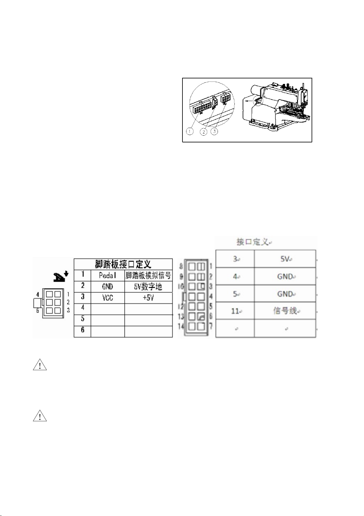
第1 章 产品接口
1. 1 接口插头连接
将脚踏板及机头的各连接插头安
插到控制器后面对应的插座上如图11 所示,各插座名称如图1-2 所示。
连接好,请检查插头是否插牢.
例图1-2 所示。连接好,请检
查插头是否插牢.LED灯和传感
器插座;②抬压脚电磁铁插
例图1-1 AHE 系列控制器图
座;脚踏板插座。
Connect the pedal and the nose of the plug placed behind the controller
corresponding to the socket as shown in figure 1-1, the name of the socket as
shown in figure 1-2. Connection is good, please check whether the plug is
stuck. Example shown in figure 1-2. Connection is good, please check whether
the plug is stuck. LED lights and sensors socket; (2) the presser foot
electromagnet socket; The pedals socket.
图1-2 控制器接口定义
:使用正常的力量插不进去时,请检查插头与插座是否匹配,插入方向
或针的方向是否正确!照明灯接口和传感器接口都是1*2 的接口,请注意区
分。
:When using normal power plug is not in, please check whether the plug and
socket match, the direction of the needle insertion direction or whether it
is right! Light interface and sensor interfaces are 1 * 2, please pay
attention to distinguish.
— 12 —
1.2 接线与接地(Wiring and grounding )
必须要做好系统的接地工程,请合格的电气工程人员予以施工。产品通电
及投入使用前,必须确保电源插座AC 输入端已安全可靠的接地。系统的接地
线为黄绿线,该地线请务必可靠连接至电网安全保护接地上,以保证安全使
用,并可防止出现异常情况。
Must prepare system grounding engineering, please qualified electrical
engineering construction. Product power and put into use before, must ensure
that the power socket AC input is safe and reliable grounding. Grounding line
is yellow green line in the system, the ground please reliable connection to
the network security protection on the ground, to ensure the safe use, and
can prevent the abnormal situation.
:所有电源线、信号线、接地线等接线时不要被其它物体压到或过度扭
曲,以确保使用安全!
All power cables, signal lines, grounding line don’t pressed to by other
objects such as wiring or excessive distortion, to ensure the safety of use!
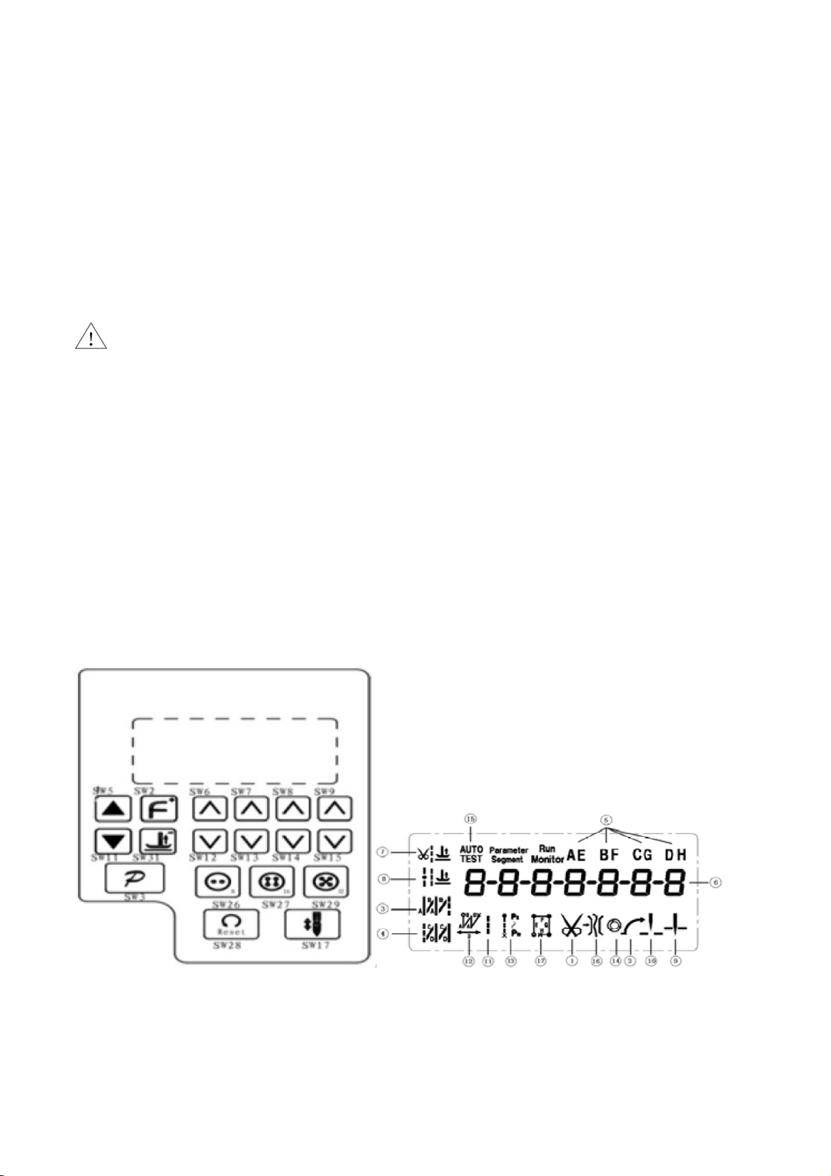
第 2 章 操作面板使用说明(Chapter 2 operation panel instructions )
2.1 操作面板的显示说明(The operation panel display)
根据系统工作状态,操作面板的液晶屏模块将显示当前的缝纫模式、各种参数、前/后
固缝设置,以及抬压脚、停针位、剪线、慢速起缝等液晶字符。H-12 操作面板液晶屏功
能图标显示说明如下所示。
Based on the system working
status,operation panel of the LCD panel
module will display the current sewing
patterns, all kinds of parameters,
before/after solid seam Settings, as well
as the presser foot, needle, thread, such
as slow up seam LCD characters. H — 12
operation panel LCD screen function icon
is displayed as shown below.
图2-1 H-12 操作面板外观界面 图2-2 H-12 操作面板液晶显示屏图示
— 13 —
 Loading…
Модели и характеристики
| Игла | № иглы | Номер темы | Диаметр кнопки (мм) | Размер отверстия кнопки(мм) | Автоматический триммер | Высота прижимной лапки (мм) | Скорость шитья (Spm) | Объем (мм) | Вес (кг) | |
|---|---|---|---|---|---|---|---|---|---|---|
| TQ × 1 # 16 (# 14 ~ # 18) TQ × 7 # 16 (# 14 ~ # 18) | 1 | 1 | 10-28мм | Х (2,5 ~ 6,5) Y (2,5 ~ 6,5) | √ | 9 | 1500 | 550 * 3900 * 360 | 30/40 |