- Manuals
- Brands
- Puritan Bennett Manuals
- Fan
- 840
- Service manual
-
Contents
-
Table of Contents
-
Troubleshooting
-
Bookmarks
Quick Links
840
Service Manual
V e n t i l a t o r S y s t e m
4-070496-00 Rev K
August 2010
Related Manuals for Puritan Bennett 840
Summary of Contents for Puritan Bennett 840
-
Page 1
Service Manual V e n t i l a t o r S y s t e m 4-070496-00 Rev K August 2010… -
Page 3
Nothing in this manual shall limit or restrict in any way Puritan Bennett’s right to revise or otherwise change or modify the equipment (including its software) described herein, without notice. In the absence of an express, written agreement to the contrary, Puritan Bennett has no obligation to furnish any such revisions, changes, or modifications to the owner or user of the equipment (including its software) described herein. -
Page 4
In case of fire or a burning smell, immediately disconnect the ventilator from the oxygen supply, facility power, and BPS. • When handling any part of the Puritan Bennett 840 Ventilator System, always follow your hospital infection control guidelines for handling infectious material. -
Page 5
• Patients on life-support equipment should be appropriately monitored by competent medical personnel and suitable monitoring devices. • The Puritan Bennett 840 Ventilator System is not intended to be a comprehensive monitoring device and does not activate alarms for all types of dangerous conditions for patients on life-support equipment. -
Page 6
While this manual covers the ventilator configurations currently supported by Puritan Bennett, it may not be all-inclusive and may not be applicable to your ventilator. You should ensure you have the most current applicable version of this manual; if in doubt, contact Puritan Bennett or visit the Puritan Bennett product manual Web page at http://www.puritanbennett.com/serv/manuals.aspx… -
Page 7: Table Of Contents
2.3.3 Exhalation module………………… 2-38 2.3.3.1 Exhalation module components …………. 2-39 2.3.3.2 Exhalation module operation …………..2-40 2.3.4 806 Compressor Unit ………………2-43 2.3.4.1 806 Compressor unit components …………2-43 2.3.4.2 806 Compressor unit operation………….. 2-46 Puritan Bennett 800 Series Ventilator System Service Manual…
-
Page 8
2.6.3 Pressure transducer autozero…………….2-115 2.6.4 Power monitoring and power fail handling …………. 2-117 2.6.4.1 Loss of power source …………….2-117 2.6.4.2 Supply voltage monitoring …………..2-118 2.7.1 Safety valve open (SVO) state…………….2-118 Puritan Bennett 800 Series Ventilator System Service Manual… -
Page 9
4.2.10.2 External Test Control: Performing remote ventilator testing ….. 4-9 4.2.10.3 Exp Valve Calibration …………….4-9 4.2.10.4 Vent Inop Test………………4-12 4.2.10.5 Flow Sensor Calibration…………….4-13 4.2.10.6 Atmospheric Pressure Transducer calibration………. 4-15 Puritan Bennett 800 Series Ventilator System Service Manual… -
Page 10
6.12 How to troubleshoot GUI LCD screen messages ……….. 6-109 6.12.1 Example 1: Missing data key information …………6-109 6.12.2 Example 2: No communication between the GUI and BDU……6-111 6.12.3 Example 3: POST or Background check errors ……….6-112 viii Puritan Bennett 800 Series Ventilator System Service Manual… -
Page 11
8.13 Repairing the 10.4-inch GUI ………………8-8 8.13.1 Removing or installing the 10.4-inch GUI when mounted on RTA cart….8-8 8.13.2 Removing or installing the 10.4-inch GUI when mounted on Puritan Bennett 800 Series Ventilator Compressor Mount Cart or Puritan Bennett 800 Series Ventilator Pole Cart……………. -
Page 12
8.15 Breath delivery unit (BDU) ………………8-50 8.15.1 Removing BDU from RTA cart …………….. 8-53 8.15.2 Removing BDU from Puritan Bennett 800 Series Ventilator Compressor Mount Cart or Puritan Bennett 800 Series Ventilator Pole Cart..8-53 Puritan Bennett 800 Series Ventilator System Service Manual… -
Page 13
8.15.4 Installing BDU onto RTA cart …………….8-55 8.15.5 Installing BDU onto Puritan Bennett 800 Series Ventilator Compressor Mount Cart or Puritan Bennett 800 Series Ventilator Pole Cart ..8-55 8.15.6 Analog interface (AI) PCB and breath delivery (BD) CPU PCB……8-56 8.15.6.1 Removing AI PCB or BD CPU PCB ………… -
Page 14
8.17.17 Compressor assembly …………….. 8-121 8.17.17.1 Removing the compressor assembly ………… 8-121 8.17.17.2 Replacing the coalescing filter element ……….8-122 8.17.18 Replacing the compressor panels …………..8-123 8.17.19 Reinstalling the plenum assembly…………..8-124 Puritan Bennett 800 Series Ventilator System Service Manual… -
Page 15
8.19.4.2 Installing casters on RTA cart …………..8-151 8.19.5 Removing casters from Puritan Bennett 800 Series Ventilator Compressor Mount Cart or Puritan Bennett 800 Series Ventilator Pole Cart … 8-151 8.19.6 Installing casters on Puritan Bennett 800 Series Ventilator Compressor Mount Cart or Puritan Bennett 800 Series Ventilator Pole Cart ..8-152 8.19.7 Removing/installing GUI mount on all carts……….. -
Page 16
Contents Parts list 9.1 How to use this parts list ………………… 9-1 9.2 Puritan Bennett 840 Ventilator System patient system and accessories ……. 9-3 9.2.1 Puritan Bennett 840 Ventilator System NeoMode patient system and accessories ………………..9-6 9.3 Flex arm assembly, oxygen and air hose assemblies, power cords ……9-8 9.3.1 Flex arm assembly ……………….. -
Page 17
RTA cart, Puritan Bennett 800 Series Ventilator Compressor Mount Cart, and Puritan Bennett 800 Series Ventilator Pole Cart ……2-6 Figure 2-8. -
Page 18
AC panel …………. 2-63 Figure 2-47. Puritan Bennett 840 Ventilator System interconnect diagram – AC panel … . 2-64 Figure 2-48. -
Page 19
/CAL In Progress indicator……… 4-20 Figure 5-1. Puritan Bennett 840 ventilator side view — PTS 2000 port ……5-9 Figure 5-2. -
Page 20
Adding ferrites to air and oxygen transducer harnesses ……8-66 xviii Puritan Bennett 800 Series Ventilator System Service Manual… -
Page 21
Removing existing brackets ……….8-128 Puritan Bennett 800 Series Ventilator System Service Manual… -
Page 22
Bennett 800 Series Ventilator Pole Cart ……..8-154 Figure 9-1. Puritan Bennett 840 Ventilator System patient system and accessories ….9-5 Figure 9-2. -
Page 23
Puritan Bennett 800 Series Ventilator Pole Cart ……. . 9-92… -
Page 24
Figures This page is intentionally blank. xxii Puritan Bennett 800 Series Ventilator System Service Manual… -
Page 25
Recommended separation distances between portable and mobile RF communications equipment and the Puritan Bennett 840 Ventilator System ……1-14 Table 1-7. -
Page 26
Table 6-2. Puritan Bennett 840 Ventilator System diagnostic codes ……6-7 Table 6-3. -
Page 27: General Information
BPS, which is located in the BDU shelf. The Puritan Bennett 800 Series Ventilator Pole Cart can also be used with a one-hour battery or an optional four-hour battery, located in the cart base. The Puritan Bennett 800 Series Ventilator Pole Cart cannot be used with a compressor.
-
Page 28: Configuration Information
An external air source is required when performing service mode calibrations and performance verification testing. 1.3 Configuration information The Puritan Bennett 840 Ventilator System is available in a variety of versions, intended to meet differing needs and regulations throughout the world. The major differences in configuration among ventilators are listed below: Electrical requirements: Available in 100 V, 50/60 Hz;…
-
Page 29: Accessories
“Part numbers” appendix of the Puritan Bennett 800 Series Ventilator System Operator’s and Technical Reference Manual for patient circuit ordering information. Humidification device: The Puritan Bennett 840 Ventilator System supports the use of an optional humidification device, including a heated humidifier, heat and moisture exchanger (HME), or heated wire.
-
Page 30: Specifications
(41 in. high x 27 in. wide x 33 in. deep with wheels in outermost position) Puritan Bennett 800 Series Ventilator Pole Cart: 1041mm high x 686 mm wide x 839 mm deep (41 in. high x 27 in. wide x 33 in. deep with wheels in outermost position) 804 Compressor: 417 mm high x 458 mm wide x 362 mm deep (16.4 in.
-
Page 31
, 50 cmH O; P , 3 cmH O. Input power specifications are for ventilators with Fisher & Paykel MR730 MEAN SENS humidifiers. (Humidifier connection only available on 100 – 120 V ventilators.) Puritan Bennett 800 Series Ventilator System Service Manual… -
Page 32
Every 2 months when storage temperature is 41 to 50 C (105 to122 F) NOTE: BPS battery life specifications are approximate. To ensure maximum battery life, maintain full charge and minimize the number of complete discharges. Puritan Bennett 800 Series Ventilator System Service Manual… -
Page 33: Figure 1-1. Remote Alarm (Nurse’s Call) Port Pinout (View From Back Of Gui)
The remote alarm port is a 4-pin female connector. Allowable current is 500 mA at 30 V DC (maximum). Signal Normally closed (NC) Relay common Normally open (NO) Not connected Figure 1-1. Remote alarm (nurse’s call) port pinout (view from back of GUI) Puritan Bennett 800 Series Ventilator System Service Manual…
-
Page 34: Figure 1-2. Puritan Bennett 840 Ventilator System Rs-232 Serial Port Pinout
RS-232 (serial) port (Figure 1-2). A 9-pin male connector configured as data terminal equipment capabilities (cont) (DTE). Allowable current is 0.2 A at 10 V DC (maximum). Figure 1-2. Puritan Bennett 840 Ventilator System RS-232 serial port pinout Signal Not connected…
-
Page 35: Compliance And Approvals
General information 1.6 Compliance and approvals The Puritan Bennett 840 Ventilator System was developed in accordance with pertinent North American and International standards (Table 1-2). The manufacturing facility for this product is certified to EN ISO 13485:2000 (ISO 13485:1996) Quality Systems — Medical Devices — Particular Requirements for the Application of ISO 9001:1994.
-
Page 36
220 – 240 V, 60 Hz EN 60601-1:1990 EN 60601-1 Amendment 1:1993 EN 60601-1 Amendment 11:1993 EN 60601-1 Amendment 12:1993 EN 60601-1 Amendment 2:1995 EN 60601-1 Amendment 13:1996 IEC 60601-2-12:2001 EN 60601-1-2:2001+A1:2006 Manufacturer self- certification 1-10 Puritan Bennett 800 Series Ventilator System Service Manual… -
Page 37: Manufacturer’s Declaration
Puritan Bennett 800 Series Ventilator System Operator’s and Technical Reference Manual. Warning • The Puritan Bennett 840 Ventilator System should not be used adjacent to or stacked with other equipment, except as specified in this manual and the Puritan Bennett 800 Series Ventilator System Operator’s and Technical Reference Manual.
-
Page 38: Table 1-4. Electromagnetic Immunity
Table 1-4: Electromagnetic Immunity The Puritan Bennett 840 Ventilator System is intended for use in the electromagnetic environment specified below. The customer or the user of the Puritan Bennett 840 Ventilator System should ensure it is used in such an environment.
-
Page 39: Table 1-5. Electromagnetic Immunity — Conducted And Radiated Rf
Table 1-5: Electromagnetic immunity – conducted and radiated RF The Puritan Bennett 840 Ventilator System is intended for use in the electromagnetic environment specified below. The customer or the user of the Puritan Bennett 840 Ventilator System should ensure it is used in such an environment. Immunity test…
-
Page 40: Table 1-6. Recommended Separation Distances Between Portable And Mobile Rf Communications Equipment And The Puritan Bennett 840 Ventilator System
If the measured field strength in the location in which the Puritan Bennett 840 Ventilator System is used exceeds the applicable RF compliance level above, the Puritan Bennett 840 Ventilator System should be observed to ver- Puritan Ben- ify normal operation.
-
Page 41
General information Table 1-6: Recommended separation distances between portable and mobile RF communications equipment and the Puritan Bennett 840 Ventilator System (continued) For transmitters rated at a maximum output power not listed above, the recommended separation distance d in meters (m) can be determined using the equation applicable to the frequency of the transmitter, where P is the maximum output power rating of the transmitter in watts (W) according to the transmitter manufacturer. -
Page 42: Table 1-7. Compliant Cables
General information Table 1-7: Compliant cables Puritan Bennett does not supply remote alarm (nurse call) or serial port cables. In order to maintain compliance to International Electromagnetic Compatibility (EMC) standards, Puritan Bennett recommends using shielded cables for these applications. Warning…
-
Page 43: Technical Information
General information 1.7 Technical information Refer to Table 1-8 for Puritan Bennett 840 Ventilator System miscellaneous technical information. NOTE: When pressure units are set to hPa, pressure delivery and spirometry are subject to an additional 2% error. Table 1-8: Technical information Maximum limited pressure 127.5 cmH…
-
Page 44
Inspiratory pneumatics: 50 mL 5 mL Expiratory pneumatics: 1000 mL 25 mL (including expiratory filter and collector vial) The Puritan Bennett 840 Ventilator System automatically adjusts for volume losses due to gas compressibility (that is, automatic compliance compensation), subject to a maximum delivered volume of 2500 mL. -
Page 45: Range, Resolution, Accuracy, And New Patient/Default Settings
Pediatric: 15 s Adult: 20 s Apnea mandatory type Range: VC or PC Resolution: N/A Accuracy: N/A New patient: PC with NEONATAL patient circuit VC with PEDIATRIC or ADULT patient circuit 1-19 Puritan Bennett 800 Series Ventilator System Service Manual…
-
Page 46
New patient: Maximum of 3* mL or (7.25 x IBW); with NEONATAL patient circuit (7.25 x IBW); with PEDIATRIC or ADULT patient circuit *Assumes NeoMode 2.0 software option is installed Normal (non-apnea) ventilation 1-20 Puritan Bennett 800 Series Ventilator System Service Manual… -
Page 47
Range: HME, non-heated expiratory tube, or heated expiratory tube Resolution: Not applicable Accuracy: Not applicable New patient value: previous setting Humidifier volume Range: 100 mL to 1000 mL Resolution: 10 mL New patient value: previous setting 1-21 Puritan Bennett 800 Series Ventilator System Service Manual… -
Page 48
VC with PEDIATRIC or ADULT patient circuit Mode Range: A/C, SIMV, SPONT, or BILEVEL Resolution: Not applicable Accuracy: Not applicable New patient: SIMV with NEONATAL patient circuit A/C with PEDIATRIC or ADULT patient circuit 1-22 Puritan Bennett 800 Series Ventilator System Service Manual… -
Page 49
Accuracy: 0.1 + 0.6% of setting)/min averaged over 60 seconds or 5 breaths, whichever occurs last New patient: 20/min with NEONATAL patient circuit 14/min with PEDIATRIC patient circuit 10/min with ADULT patient circuit 1-23 Puritan Bennett 800 Series Ventilator System Service Manual… -
Page 50
*Assumes NeoMode 2.0 software option is installed Trigger type Range: Flow (V-TRIG) NEONATAL patient circuit Pressure or flow (P-TRIG or V-TRIG) with PEDIATRIC or ADULT patient circuit Resolution: Not applicable Accuracy: Not applicable New patient: Flow (V-TRIG) 1-24 Puritan Bennett 800 Series Ventilator System Service Manual… -
Page 51
SUPP MEAN is rejected. Refer to the Technical Reference section of part of the Puritan Bennett 800 Series Ventilator System Operator’s and Technical Reference Manual for more details. Vent type Range: INVASIVE or NIV (non-invasive) -
Page 52
Resolution: 1 mL for 1 to 100 mL; 5 mL for 100 to 400 mL; 10 mL for 400 to 2500 mL New patient: 7.25 x IBW x 0.70 when vent type is INVASIVE; OFF when vent type is NIV 1-26 Puritan Bennett 800 Series Ventilator System Service Manual… -
Page 53
O for PEEP 20 cmH 1.0 cmH Sensor Range: Enabled, Disabled, or Calibration Resolution: Not applicable New patient value: Enabled NOTE: The O sensor must be for the High/Low delivered O Enabled alarm to function. 1-27 Puritan Bennett 800 Series Ventilator System Service Manual… -
Page 54
O for 10 to 130 cmH MEAN (formerly P CIRC Accuracy: ± (3 + 4% of reading) cmH O relative to pressure measured at the exhalation side of the patient wye. 1-28 Puritan Bennett 800 Series Ventilator System Service Manual… -
Page 55: Tools, Equipment, And Service Materials
1.9 Tools, equipment, and service materials The tools, equipment, and service materials listed in Table 1-10 are used to service the Puritan Bennett 840 Ventilator System. Refer to Chapter 5 for a list of required tools, equipment, and service materials specific to performance verification.
-
Page 56: Table 1-10. Tools, Equipment, And Service Materials
Digital multimeter patch cords G-061567-00 Performance verification (optional) * These parts may be purchased individually or by ordering a Puritan Bennett 840 VTS Accessories Kit, P/N 4-076599-00. Disinfectant/cleaner The following solutions are acceptable General cleaning for disinfecting/cleaning the Puritan…
-
Page 57
Filter, expiratory bacteria filter DAR 351P19005 Performance verification * These parts may be purchased individually or by ordering a Puritan Bennett 840 VTS Accessories Kit, P/N 4-076599-00. Filter, expiratory bacteria filter, 4-070305-00 Performance verification reusable (Re/X800) Filter, inspiratory, Re/Flex… -
Page 58
• One available TCP/IP network port with BNC connector (if software download desired) * These parts may be purchased individually or by ordering a Puritan Bennett 840 VTS Accessories Kit, P/N 4-076599-00. Pneumatic calibration analyzer or Puritan Bennett PTS 2000 Performance… -
Page 59
Test lung, 4 L 4-075578-00 Performance verification Tie wraps 4-000003-00 (small) Various places 4-000004-00 (large) * These parts may be purchased individually or by ordering a Puritan Bennett 840 VTS Accessories Kit, P/N 4-076599-00. 1-33 Puritan Bennett 800 Series Ventilator System Service Manual… -
Page 60: Series Ventilator Compressor Mount Cart, And Puritan Bennett 800 Series Ventilator Pole Cart
N-4800168 Replacing casters (RTA cart) Wye, patient circuit *4-000338-00 SST, performance verification * These parts may be purchased individually or by ordering a Puritan Bennett 840 VTS Accessories Kit, P/N 4-076599-00. 1-34 Puritan Bennett 800 Series Ventilator System Service Manual…
-
Page 61: Periodic Maintenance
Table 1-11 lists the periodic maintenance activities required for the Puritan Bennett 840 Ventilator System. See the Ventilator Information screen for total hours of operation for the ventilator and compressor. For details on patient system maintenance, refer to the Puritan Bennett 800 Series Ventilator System Operator’s and Technical Reference Manual.
-
Page 62
Use appropriate preventive maintenance kit (see Table 1-12). Every 15,000 hours NOTE: If any part found in a preventive maintenance kit requires replacement before the recommended interval elapses, consider installing the entire kit anyway. 1-36 Puritan Bennett 800 Series Ventilator System Service Manual… -
Page 63: Service Kits
General information 1.11 Service kits Table 1-12 lists the Puritan Bennett 840 Ventilator System service kits. Chapter 9 lists the mounting kits available for the ventilator. Table 1-12: Service kits Interval Description Part no. Kit contents 10,000 hours 9.4“ GUI and BDU…
-
Page 64
Filter element for water trap assembly Main inlet filter Outlet filter for solenoid assembly Tie wrap, large, for air dryer assembly Tie wraps, small for fan harnesses (qty. 2) Tinnerman clips (qty. 6) 1-38 Puritan Bennett 800 Series Ventilator System Service Manual… -
Page 65: Controls And Indicators
1.12 Controls and indicators Refer to Figure 1-3 through Figure 1-10 and Table 1-13 through Table 1-20 for ventilator controls and indicators. 10 11 Figure 1-3. Monochrome GUI front view (showing all keys) 1-39 Puritan Bennett 800 Series Ventilator System Service Manual…
-
Page 66: Table 1-13. Gui Front View
Color GUI (9.4 inch screen): Key present but inactive Monochrome GUI: Display brightness key. Allows you to adjust screen brightness when you hold down this key while turning the knob. (US version only) 1-40 Puritan Bennett 800 Series Ventilator System Service Manual…
-
Page 67
You cannot reset a DEVICE ALERT alarm. Displays basic operating information about the ventilator. US version only 1-41 Puritan Bennett 800 Series Ventilator System Service Manual… -
Page 68
0.5 and 2 seconds. Pressing and holding this key initiates a manual inspiratory pause extending inspiration up to 7 seconds. Cancels a proposed setting. 1-42 Puritan Bennett 800 Series Ventilator System Service Manual… -
Page 69
Gray normal ventilator operation indicator. Indicator appears unilluminated when no ventilator inoperative condition exists. non-US version US version text is not visible when no ventilator inoperative condition exists. US version 1-43 Puritan Bennett 800 Series Ventilator System Service Manual… -
Page 70
Red safety valve open (SVO) indicator. Illuminates when the ventilator has entered its safe state and opened its safety valve to allow the patient to breathe unassisted from room air. non-US version US version 1-44 Puritan Bennett 800 Series Ventilator System Service Manual… -
Page 71
(battery symbol) is lit, ventilator is operating on BPS, and AC power is insufficient to support ventilator operation. During BPS operation, power to the compressor unit and the humidifier outlet (if available) is off. BATTERY US version only 1-45 Puritan Bennett 800 Series Ventilator System Service Manual… -
Page 72
Green normal ventilator operation indicator steadily lit. This indicator is off if the ventilator is not in a ventilation mode, for example, during service mode or short self test (SST). 1-46 Puritan Bennett 800 Series Ventilator System Service Manual… -
Page 73: Figure 1-4. 10.4-Inch Gui Rear View
10.4-inch GUI only: Two serial ports with 9-pin male connector configured as data terminal equipment (DTE). NOTE: Allowable current is 0.2 A at 10 V DC (maximum). RS-232 NULL Null modem port (9.4-inch and 10.4-inch GUI) 1-47 Puritan Bennett 800 Series Ventilator System Service Manual…
-
Page 74: Figure 1-5. Bdu Front View
Index Labeling Function (Figure 1-5) EXHAUST port BDU exhaust port. Gas is vented to atmosphere. Ventilator operation indicators Red ventilator inoperative indicator. (See Table 1-13, item 15.) non-US version US version 1-48 Puritan Bennett 800 Series Ventilator System Service Manual…
-
Page 75
Gray normal GUI indicator. Indicator appears unilluminated when no loss of GUI condition exists. non-US version US version text is not visible when no loss of GUI condition exists. US version 1-49 Puritan Bennett 800 Series Ventilator System Service Manual… -
Page 76
2.3 A (270 VA) with a maximum leakage current of 50 A. To patient port Ventilator outlet From patient port Expiratory limb connector on exhalation filter (Collector vial drain port) Collector vial drain port. Use to attach drainage bag. 1-50 Puritan Bennett 800 Series Ventilator System Service Manual… -
Page 77: Figure 1-6. Bdu I/O Panel
BDU, the ventilator is placed into service mode (for example, to run EST). PTS 2000 Puritan Bennett PTS 2000 Performance Test System connection. Data key connection Caution Do not remove the data key. The data key cover can only be removed with a screwdriver.
-
Page 78
General information Table 1-16: BDU I/O panel (continued) Index Labeling Function (Figure 1-6) Compressor data cable connection Compressor US version GUI cable connection Display (GUI) US version 1-52 Puritan Bennett 800 Series Ventilator System Service Manual… -
Page 79: Figure 1-7. Bdu Right-Side Panel
Labeling Function (Figure 1-7) Ventilator circuit breaker for compressor and humidifier NOTE: A humidifier connection is only available on 100 – 120 V ventilators. Compressor & humidifier circuit breaker US version 1-53 Puritan Bennett 800 Series Ventilator System Service Manual…
-
Page 80
A common grounding point for the entire ventilator. Maximum allowed output to auxiliary mains socket (compressor electrical connection) Compressor outlet: 5.6 A max US version 1-54 Puritan Bennett 800 Series Ventilator System Service Manual… -
Page 81: Figure 1-8. Bdu Rear View
(High-pressure air fitting) DISS male, DISS female, NIST, Air Liquide, or SIS fitting (High-pressure oxygen DISS male, DISS female, NIST, Air Liquide, or SIS fitting fitting) Figure 1-9. GUI rear view 1-55 Puritan Bennett 800 Series Ventilator System Service Manual…
-
Page 82: Table 1-19. Gui Rear View
Labeling Function (Figure 1-9) (Warning label) Warns user of hazards associated with the operation of the Puritan Bennett 840 Ventilator System and GUI (Serial number label) Unique assigned number. Must be the same as the GUI serial number stored on the data key.
-
Page 83: Figure 1-10. 802 Bps Controls And Indicators
General information Figure 1-10. 802 BPS controls and indicators Figure 1-11. 803 BPS controls and indicators 1-57 Puritan Bennett 800 Series Ventilator System Service Manual…
-
Page 84: Figure 1-12. Puritan Bennett 800 Series Ventilator Compressor Mount Cart Charging Status And
General information Figure 1-12. Puritan Bennett 800 Series Ventilator Compressor Mount Cart charging status and battery indicator labels 1-58 Puritan Bennett 800 Series Ventilator System Service Manual…
-
Page 85: Figure 1-13. Puritan Bennett 800 Series Ventilator Pole Cart Charging Status And
General information Figure 1-13. Puritan Bennett 800 Series Ventilator Pole Cart charging status and battery indicator labels Table 1-20: BPS controls and indicators Labeling Function Index (Figure 1-10) 802 BPS charging status. When the ventilator is operating on mains power, the top symbol (green LED next to gray battery icon) indicates that the BPS is charged, and the bottom symbol (yellow LED next to gray battery icon) indicates that the BPS is charging.
-
Page 86
All countries Index (Figure 1-12) Charging status on Puritan Bennett 800 Series Ventilator Compressor Mount Cart: Indicates the charging status of the BPS. A yellow LED next to the partially full battery icon indicates the battery is charging. A green LED next to the full battery icon indicates the battery is charged. -
Page 87: Onscreen Symbols And Abbreviations
Manual to interpret these. 1.14 Ventilator serial numbers and software version The Puritan Bennett 840 Ventilator System serial numbers and software versions can be displayed on the GUI upper subscreen. On the GUI upper screen, select the VENT CONFIG button. The ventilator configuration subscreen displays the current software revisions for the BDU, GUI, compressor, and audible alarm subsystem.
-
Page 88
General information This page intentionally blank. 1-62 Puritan Bennett 800 Series Ventilator System Service Manual… -
Page 89: Theory Of Operation
ECTION H A PT ER Theory of operation This chapter details the operational theory of the Puritan Bennett™ 840 Ventilator System and contains the following information: • description of major ventilator assemblies • overview of ventilator operation • description of the pneumatic system •…
-
Page 90: Breath Delivery Unit (Bdu)
Ventilator Compressor Mount Cart, and Puritan Bennett 800 Series Ventilator Pole Cart 2.1.1 Breath delivery unit (BDU) The BDU, shown in Figure 2-2, is the core of the Puritan Bennett 840 Ventilator System. Its pneumatic system, under control of the breath delivery (BD) central processing unit (CPU), mixes oxygen and air and controls gas flow to the patient.
-
Page 91: Graphic User Interface (Gui)
GUI. The GUI CPU monitors BDU communications. In turn, the GUI displays patient and ventilator performance information. Figure 2-3. 10.4-inch GUI Puritan Bennett 800 Series Ventilator System Service Manual…
-
Page 92: Compressor Unit
803 BPS will operate the ventilator for up to four hours with new, fully charged batteries. Neither BPS supplies the compressor unit or the humidifier with electrical power. The ventilator automatically switches back to AC power when facility power returns within the required limits. Puritan Bennett 800 Series Ventilator System Service Manual…
-
Page 93: Cart
The optional carts are shown in Figure 2-7. The cart mounts system components and accessories, including the compressor unit on the RTA and Puritan Bennett 800 Series Ventilator Compressor Mount Carts. They also provide mobility for the ventilator. Brakes on the front casters prevent the cart from rolling and turning.
-
Page 94: Patient System
Theory of operation 8-01119 Figure 2-7. RTA cart, Puritan Bennett 800 Series Ventilator Compressor Mount Cart, and Puritan Bennett 800 Series Ventilator Pole Cart 2.1.6 Patient system The patient system (adult, reusable version shown in Figure 2-8) includes reusable or single- patient use tubing plus an inspiratory filter that prevents gas-borne particles from exiting the ventilator.
-
Page 95: Operational Overview
GUI: high circuit pressure limit, breath phase, breath mode, autozero offsets, inspiratory time, apnea interval, target pressure for pressure controlled breaths, breath phase start, and time stamp. Puritan Bennett 800 Series Ventilator System Service Manual…
-
Page 96: Figure 2-10. Puritan Bennett 840 Ventilator System Block Diagram
Figure 2-10. Puritan Bennett 840 Ventilator System block diagram The GUI logs an event in the diagnostic log and declares a ventilator inoperative condition if: • Any raw signal data from three BDU transmissions within 24 hours is corrupted.
-
Page 97
BDU CPU to control the PSOLs. As a result, the ventilator supplies mixed breathing gas to the patient according to operator-set variables. The mixed air and oxygen passes through the patient circuit external to the ventilator. Puritan Bennett 800 Series Ventilator System Service Manual… -
Page 98
In case of a malfunction that prevents software from opening the safety valve, there is also an analog circuit that opens the safety valve if system pressure exceeds 100 to 120 cmH 2-10 Puritan Bennett 800 Series Ventilator System Service Manual… -
Page 99: Pneumatic System
Theory of operation 2.3 Pneumatic system This section describes the Puritan Bennett 840 Ventilator System pneumatics, as follows: • Inspiratory module: Contains the following pneumatic subsystems: – Gas supply conditioning subsystem – Flow control subsystem – Safety valve/inspiration monitoring subsystem •…
-
Page 100: Figure 2-12. Pneumatic System Diagram
Theory of operation Figure 2-12. Pneumatic system diagram 2-12 Puritan Bennett 800 Series Ventilator System Service Manual…
-
Page 101: Table 2-1. Pneumatic Component Descriptions
Measures oxygen or air flow before PSOL. Regulator, oxygen/air Reduces input supply pressure (35 to 100 psig, flow up to 200 L/min REG1 BTPS) to output pressure (9 psig minimum to 12 psig maximum). REG2 2-13 Puritan Bennett 800 Series Ventilator System Service Manual…
-
Page 102
Measures exhalation flow. Solenoid, autozero, expiratory +6 V, three-way solenoid valve. Energized (common to normally SOL2 pressure transducer closed) when transducer is autozeroed. De-energized (common to normally open) all other times. 2-14 Puritan Bennett 800 Series Ventilator System Service Manual… -
Page 103
Water trap Collects condensate as the compressed air cools in the heat exchanger. Automatically drains collected water to the housing base where it evaporates. 2-15 Puritan Bennett 800 Series Ventilator System Service Manual… -
Page 104: Inspiratory Module
The inspiratory module, which is part of the BDU, is shown in Figure 2-13 and Figure 2-14. It includes the gas supply conditioning, flow control, and safety valve/inspiration monitoring subsystems. Figure 2-15 is a diagram of the inspiratory module gas flow. Figure 2-13. Inspiratory module 2-16 Puritan Bennett 800 Series Ventilator System Service Manual…
-
Page 105: Gas Supply Conditioning Subsystem
It does this by sending signals to the electronics when a gas source falls below a minimum pressure. Figure 2-17 illustrates the gas flow through gas supply conditioning subsytem. 2-17 Puritan Bennett 800 Series Ventilator System Service Manual…
-
Page 106: Figure 2-16. Gas Supply Conditioning Subsystem
Figure 2-16. Gas supply conditioning subsystem Figure 2-17. Gas supply conditioning subsystem gas flow diagram 2.3.1.1.1 Gas supply conditioning subsystem components The oxygen side of the gas supply conditioning subsystem includes the following components: 2-18 Puritan Bennett 800 Series Ventilator System Service Manual…
-
Page 107
• The oxygen pressure valve (TP1) checks the oxygen regulator setting (REG1). • The oxygen pneumatic noise filter (F7), housed in the flow sensor manifold, conditions gas flow by eliminating swirling of gas induced by elbows and restrictions. 2-19 Puritan Bennett 800 Series Ventilator System Service Manual… -
Page 108
• The air pressure valve (TP2) checks the oxygen regulator setting (REG2). • The air pneumatic noise filter (F6), housed in the flow sensor manifold, conditions gas flow by eliminating swirling of gas induced by elbows and restrictions. 2-20 Puritan Bennett 800 Series Ventilator System Service Manual… -
Page 109: Figure 2-18. Gas Supply Conditioning Subsystem Components
Theory of operation Oxygen inlet filter (F3) Oxygen impact filter (F1) Oxygen Filters (F1 and F3) Air inlet filter (F2) Oxygen/air pressure switches (PS1/PS2) Figure 2-18. Gas supply conditioning subsystem components 2-21 Puritan Bennett 800 Series Ventilator System Service Manual…
-
Page 110
(F1), traps particles down to 65 m (microns) and the subsequent filter, the oxygen inlet filter (F3), traps particles down to 0.3 m (micron). The oxygen transfer tube directs oxygen to the check valve manifold. There is no check valve for oxygen. 2-22 Puritan Bennett 800 Series Ventilator System Service Manual… -
Page 111: Flow Control Subsystem
The flow control subsystem, shown in Figure 2-20 and Figure 2-19, controls the mixture and flow of oxygen and air to the patient. It is mounted on the gas supply conditioning subsystem. PSOL1 PSOL2 Figure 2-19. Flow control subsystem 2-23 Puritan Bennett 800 Series Ventilator System Service Manual…
-
Page 112: Figure 2-20. Flow Control Subsystem Gas Flow Diagram
• Q1 and Q2 use a hot film (Figure 2-21) within each sensor to measure gas velocity (flow). The hot film constitutes one leg of a bridge circuit. The bridge is supplied by a constant 2-24 Puritan Bennett 800 Series Ventilator System Service Manual…
-
Page 113: Figure 2-22. Flow Control Subsystem Components
Oxygen and air flow sensors (Q1 and Q2) with ferrites installed Oxygen and air proportional solenoid valves (PSOL1 and PSOL2) Figure 2-22. Flow control subsystem components 2-25 Puritan Bennett 800 Series Ventilator System Service Manual…
-
Page 114: Safety Valve And Inspiration Monitoring Subsystem
• A safety valve section that, under certain circumstances, vents excessive ventilator pressure and lets the patient breathe room air. • An inspiration monitoring section that monitors the pressure and oxygen concentration of the inspiratory gas. 2-26 Puritan Bennett 800 Series Ventilator System Service Manual…
-
Page 115: Figure 2-23. Safety Valve And Inspiration Monitoring Subsystem
The safety valve section includes the following components, shown in Figure 2-24: • The safety valve (SV) consists of a +12 V solenoid actuator that is normally energized (closed) while the ventilator operates. The closed valve prevents gas from escaping to the 2-27 Puritan Bennett 800 Series Ventilator System Service Manual…
-
Page 116
• The absolute pressure transducer (PA), located on the inspiratory electronics PCB, measures atmospheric pressure (psia). One port is opened to the atmosphere and one port is connected to a sealed vacuum chamber. 2-28 Puritan Bennett 800 Series Ventilator System Service Manual… -
Page 117: Figure 2-25. Safety Valve And Inspiration Monitoring Subsystem Components
Theory of operation Safety valve (SV) Seat Leaf Check valve housing Oxygen sensor Oxygen sensor port 8-0112 Inspiratory outlet manifold Figure 2-25. Safety valve and inspiration monitoring subsystem components Oxygen sensor (OS) 2-29 Puritan Bennett 800 Series Ventilator System Service Manual…
-
Page 118
O (measured at PE), components in the safety valve subsystem work together to relieve excess pressure. If pressure at the safety valve reaches nominal 115 cmH O, the valve is forced open. 2-30 Puritan Bennett 800 Series Ventilator System Service Manual… -
Page 119: Figure 2-26. Safety Valve Open Gas Flow Diagram
PEEP plus the effective working pressure for spontaneous, pressure-supported breaths. Ongoing diagnostics monitor ventilator pressures and check for severe occlusions and circuit disconnects by comparing pressure at PE and PI. 2-31 Puritan Bennett 800 Series Ventilator System Service Manual…
-
Page 120: Inspiratory Module Operation
Check valve manifold Air check valve (CV2) Compressor check valve (CV4) Air impact screen filter (F4) Air regulator (REG2) Flow sensor manifold Air pressure valve (TP2) Air pneumatic noise filter (F6) 2-32 Puritan Bennett 800 Series Ventilator System Service Manual…
-
Page 121
Inspiration monitoring. The oxygen concentration of the delivered gas is measured by the oxygen sensor (OS). The ventilator alarms if the monitored oxygen concentration is not within ±7% of the oxygen percentage setting. Pressure measurements are made by two differential pressure transducers. 2-33 Puritan Bennett 800 Series Ventilator System Service Manual… -
Page 122: Figure 2-28. Oxygen Flow Diagram
Check valve manifold Oxygen impact screen filter (F5) Oxygen regulator (REG1) Regulator vent Flow sensor manifold Oxygen pressure valve (TP1) Oxygen pneumatic noise filter (F7) Oxygen flow sensor (Q1) PSOL/SV manifold 2-34 Puritan Bennett 800 Series Ventilator System Service Manual…
-
Page 123
REG1 reduces oxygen pressure from 35 – 100 psig to 9 – 12 psig (10.5 psig nominal). It vents at a maximum of 2 L/min (outside the BDU to prevent oxygen buildup). 2-35 Puritan Bennett 800 Series Ventilator System Service Manual… -
Page 124: Patient System
A variety of optional accessories can be used in the patient circuit. Figure 2-29 shows a typical patient system configuration. Inspiratory filter (F8) Humidification device Water trap (2 PL) Figure 2-29. Patient system (minus exhalation collector vial and expiratory filter) 2-36 Puritan Bennett 800 Series Ventilator System Service Manual…
-
Page 125: Patient System Components
30 L/min with 99.99% efficiency. It has 22-mm ISO conical connections. The NeoMode DAR (PN 351919005) disposable expiratory filter and the Puritan Bennett Neo Re/x800 reusable expiratory filter are designed specifically for use with the NeoMode option.
-
Page 126: Patient System Operation
• The mounting plate, used only with neonatal patient systems, allows the ventilator to accommodate the neonatal expiratory filter. Caution To protect the exhalation assembly, always use a Puritan Bennett expiratory filter or a recommended DAR expiratory filter. 2.3.2.2 Patient system operation A predetermined oxygen/air gas mixture flows from the ventilator, through F8, and the optional humidification device.
-
Page 127: Exhalation Module Components
• The exhalation flow sensor (Q3) provides flow information on exhaled gas. Flow sensor measurements are used to determine net gas flow to the patient and spirometry. 2-39 Puritan Bennett 800 Series Ventilator System Service Manual…
-
Page 128: Exhalation Module Operation
The expiratory pressure transducer (PE), on the exhalation transducer PCB, and the exhalation flow sensor (Q3) provide readings used in breath delivery calculations. 2-40 Puritan Bennett 800 Series Ventilator System Service Manual…
-
Page 129: Figure 2-33. Exhalation Module Components
Theory of operation Exhalation flow sensor (Q3) Figure 2-33. Exhalation module components NOTE: Exhalation module parts are shown here for reference only. For assembly illustration, refer to Figure 9-18 on page 9-53. 2-41 Puritan Bennett 800 Series Ventilator System Service Manual…
-
Page 130
Theory of operation Expiratory pressure transducer autozero solenoid (SOL2) Exhalation check valve (CV5) Exhalation heater (EXH HTR) Exhalation module components (continued) 2-42 Puritan Bennett 800 Series Ventilator System Service Manual… -
Page 131: Compressor Unit
The optional, cart-mounted 806 compressor unit, shown in Figure 2-35, is the latest style compressor system available for use with the Puritan Bennett 840 Ventilator System. When AC power is present, the compressor system supplies air to the ventilator in the event that a hospital air source is unavailable or the source pressure drops below 26 psig.
-
Page 132: Figure 2-36. 806 Components
(F11) to prevent contaminants from entering the transducer. Pressure relief valve To heat exchanger Motor/compressor Silencer Cooling fans 0.3 micron filter Silencer Intake filter Filter foam Figure 2-36. 806 components 2-44 Puritan Bennett 800 Series Ventilator System Service Manual…
-
Page 133: Figure 2-37. Heat Exchanger
Theory of operation Figure 2-37. Heat exchanger Water trap Filter element Figure 2-38. 806 water trap assembly 2-45 Puritan Bennett 800 Series Ventilator System Service Manual…
-
Page 134: Compressor Unit Operation
Figure 2-40. 806 back panel 2.3.4.2 806 Compressor unit operation The 806 compressor is powered by and communicates with the Puritan Bennett 840 BDU. The BDU sends a signal to the compressor after completing POST, and the compressor enters either stand-by mode or run mode depending upon the state of the air-side pressure switch, PS2.
-
Page 135: Figure 2-41. 806 Cooling Fans
The air dryer also lowers the dew point to a temperature below ambient, preventing condensation from entering the ventilator. Figure 2-41. 806 cooling fans 2-47 Puritan Bennett 800 Series Ventilator System Service Manual…
-
Page 136: Summary Of Electrical Components
Figure 2-84. Electrical system 2.4.1 Summary of electrical components The Puritan Bennett 840 ventilator electrical system, shown in Figure 2-42, includes the following: • AC distribution components, including power cord, AC panel (circuit breakers, AC filter PCB, power relay, and other components), and power switch •…
-
Page 137: Table 2-2. Electronic Component Descriptions
Output signals from the BPS PCB include charging*, charged*, BPS model, IBATT, VBATT, and E-BP. NOTE: When the ventilator is running on battery power, the compressor and humidifier are non-operational. * indicates signal is active low 2-49 Puritan Bennett 800 Series Ventilator System Service Manual…
-
Page 138
Breath delivery (BD) CPU PCB Contains the electronics and software that control all breath delivery functions in the Puritan Bennett 840 Ventilator System. Communicates with the GUI CPU to respond to operator inputs and display ventilation parameters. Analog interface (AI) PCB Provides the interface for all analog signals in the ventilator. -
Page 139
Delivers a voltage proportional to the oxygen concentration. Ventilator alarms if the monitored oxygen concentration is not within 7% of the oxygen percentage setting. 2-51 Puritan Bennett 800 Series Ventilator System Service Manual… -
Page 140
Motor compressor AC powered and logic-controlled, supplies compressed air to the ventilator when adequate wall air pressure is unavailable. Contains internal over-temperature protection device. 2-52 Puritan Bennett 800 Series Ventilator System Service Manual… -
Page 141: Overview Of Electrical System Operation
PCB. 2.4.2 Overview of electrical system operation The Puritan Bennett 840 Ventilator System uses a dual-microprocessor architecture with an Ethernet network as the primary channel of communication between the two 68040 microprocessors. The BDU microprocessor handles the breath delivery control and monitoring functions;…
-
Page 142
Theory of operation This page intentionally blank. 2-54 Puritan Bennett 800 Series Ventilator System Service Manual… -
Page 143: Figure 2-42. Electrical System Block Diagram (10.4-Inch Gui-Trending-Enabled Cpu Pcb Shown)
Figure 2-42. Electrical system block diagram (10.4-inch GUI—Trending-enabled CPU PCB shown) Remove pages 2-55 and 2-56. (Page 2-56 is also printed on the reverse side of the foldout.) Figure 2-42. Electrical system block diagram (10.4-inch GUI—Trending-enabled CPU PCB shown) 2-55 Puritan Bennett 800 Series Ventilator System Service Manual…
-
Page 144
Theory of operation This page intentionally blank. 2-56 Puritan Bennett 800 Series Ventilator System Service Manual… -
Page 145
CPU PCB shown) Remove pages 2-57 and 2-58. (Page 2-58 is also printed on the reverse side of the foldout.) Figure 2-43. Electrical system block diagram (10.4-inch GUI—Non-Trending-enabled CPU PCB shown) 2-57 Puritan Bennett 800 Series Ventilator System Service Manual… -
Page 146
Theory of operation This page intentionally blank. 2-58 Puritan Bennett 800 Series Ventilator System Service Manual… -
Page 147
Electrical system block diagram (9.4-inch GUI—Trending-enabled CPU PCB shown) Remove pages 2-59 and 2-60. (Page 2-60 is also printed on the reverse side of the foldout.) Figure 2-44. Electrical system block diagram (9.4-inch GUI—Trending-enabled CPU PCB shown) 2-59 Puritan Bennett 800 Series Ventilator System Service Manual… -
Page 148
Theory of operation This page intentionally blank. 2-60 Puritan Bennett 800 Series Ventilator System Service Manual… -
Page 149
Electrical system block diagram (older 9.4-inch GUI shown) Remove pages 2-61 and 2-62. (Page 2-62 is also printed on the reverse side of the foldout.) Figure 2-45. Electrical system block diagram (older 9.4-inch GUI shown) 2-61 Puritan Bennett 800 Series Ventilator System Service Manual… -
Page 150: Ac Distribution Components
2.4.3.1 Power cord The Puritan Bennett 840 Ventilator System includes a detachable power cord. The power cord has an IEC-standard, three-prong connector. The plug end varies, corresponding to different country requirements.
-
Page 151: Figure 2-46. Ac Panel
Potential equalization (compressor/ connector (J2) humidifier) circuit breaker Compressor (CB2) receptacle (J4) AC filter Main circuit breaker (CB1) Power relay (K1) Fuse Auxiliary (compressor/ humidifier circuit breaker (CB2) Figure 2-46. AC panel 2-63 Puritan Bennett 800 Series Ventilator System Service Manual…
-
Page 152: Figure 2-47. Puritan Bennett 840 Ventilator System Interconnect Diagram — Ac Panel
Auxiliary mains circuit breaker Mains inlet To power supply Potential equalization point compartment Compressor outlet Power relay AC PANEL MODULE Figure 2-47. Puritan Bennett 840 Ventilator System interconnect diagram – AC panel 2-64 Puritan Bennett 800 Series Ventilator System Service Manual…
-
Page 153: Power Switch
A cover protects the power switch and prevents it from accidentally being turned off. An LED indicator beside the power switch lights to indicate that power is available to the ventilator. Power switch Indicator (S1) Figure 2-48. Power switch (S1) and indicator 2-65 Puritan Bennett 800 Series Ventilator System Service Manual…
-
Page 154: Power Supply
The power supply has no test points, and cannot be field-adjusted. Power supply voltages are displayed during the analog data display test in EST. Figure 2-49. Power supply assembly 2-66 Puritan Bennett 800 Series Ventilator System Service Manual…
-
Page 155: Figure 2-50. Puritan Bennett 840 Ventilator System Interconnect Diagram — Power Distribution
To AC inspiratory panel module POWER SUPPLY To backup power supply (BPS) (This side is located adjacent to inspiratory module) Figure 2-50. Puritan Bennett 840 Ventilator System interconnect diagram – Power distribution 2-67 Puritan Bennett 800 Series Ventilator System Service Manual…
-
Page 156: Bps
20 hours to recharge. The BPS contains a battery pack (Figure 2-53) (which includes two +12 V, lead-acid batteries and a 15 A fuse) and a PCB (Figure 2-54). Figure 2-51. 802 BPS 2-68 Puritan Bennett 800 Series Ventilator System Service Manual…
-
Page 157: Figure 2-52. 803 Bps
Theory of operation Figure 2-52. 803 BPS Fuse Figure 2-53. 802 BPS battery pack 2-69 Puritan Bennett 800 Series Ventilator System Service Manual…
-
Page 158: Figure 2-54. Bps Pcb
Theory of operation Figure 2-54. BPS PCB 2-70 Puritan Bennett 800 Series Ventilator System Service Manual…
-
Page 159: Card Cage
The card cage, shown in Figure 2-55 and Figure 2-56, includes the motherboard PCB, the BD CPU PCB, and the AI PCB. BDU CPU PCB AI PCB Motherboard PCB Figure 2-55. Card cage with all PCBs installed 2-71 Puritan Bennett 800 Series Ventilator System Service Manual…
-
Page 160: Figure 2-56. Puritan Bennett 840 Ventilator System Interconnect Diagram — Card Cage
UNIT (BDU) TEST switch (SW2) indicator GUI-to-BDU cable assy AI PCB PTS 2000 connection 9-pin BDU/compressor Data DC cable Figure 2-56. Puritan Bennett 840 Ventilator System interconnect diagram – Card cage 2-72 Puritan Bennett 800 Series Ventilator System Service Manual…
-
Page 161: Motherboard Pcb
The motherboard PCB consists of a multilayer PCB, connectors for plug-in boards and I/O interface, and related electrical filters and protective devices. AI PCB connectors BD CPU PCB connectors Figure 2-57. Motherboard PCB 2-73 Puritan Bennett 800 Series Ventilator System Service Manual…
-
Page 162: Figure 2-58. Motherboard Pcb In Place
Theory of operation Motherboard PCB Figure 2-58. Motherboard PCB in place 2-74 Puritan Bennett 800 Series Ventilator System Service Manual…
-
Page 163: Figure 2-59. Motherboard Pcb Block Diagram
EXH MOD PWR & SENS TO/FROM EXHALATION MODULE BD ALARM +12 V EXH AZ EXH MODULE CTRL INSP MOD PWR & SENS TO/FROM INSPIRATORY INSP MODULE CTRL MODULE Figure 2-59. Motherboard PCB block diagram 2-75 Puritan Bennett 800 Series Ventilator System Service Manual…
-
Page 164: Bdu Cpu Pcb
The BDU CPU PCB (Figure 2-60), in conjunction with the AI PCB, provides microprocessor control of all breath delivery functions for the Puritan Bennett 840 Ventilator System. It also communicates with the GUI CPU PCB for display and control information from the operator.
-
Page 165: Figure 2-60. Bd Cpu Pcb
• A diagnostic LED array (with supporting circuitry) indicates the status of the BD CPU PCB. During POST, they indicate the current test step. A ninth LED displays the supervisory mode status of the CPU. 2-77 Puritan Bennett 800 Series Ventilator System Service Manual…
-
Page 166
• The service mode switch is a push-button on the board edge used to activate this mode. The BD CPU PCB generates an NMI under any of these conditions: • Ethernet parity error detected • Power fail signal • A/D converter system error 2-78 Puritan Bennett 800 Series Ventilator System Service Manual… -
Page 167: Table 2-3. Novram Contents
Calculated during SST BD NOVRAM expiratory resistance Oxygen and air flow Calculated during EST BD NOVRAM sensor (Q1 and Q2) offsets Absolute pressure Calculated during PA calibration BD NOVRAM transducer (PA) offset 2-79 Puritan Bennett 800 Series Ventilator System Service Manual…
-
Page 168: Analog Interface (Ai) Pcb
• The valve control and drive circuit provides drive signals for the PSOLs, EV, and the EV stabilizer device. PTS 2000 connector Data key connector Compressor connector AI LEDs Figure 2-61. AI PCB 2-80 Puritan Bennett 800 Series Ventilator System Service Manual…
-
Page 169
The software reads this signal to determine whether the BPS is currently connected to the ventilator. • Other buffers provide conditioning for various ventilator signals. • The compressor interface circuit, in conjunction with the compressor PCB, controls and monitors the compressor operation. 2-81 Puritan Bennett 800 Series Ventilator System Service Manual… -
Page 170: Data Key Subsystem
Call your Puritan Bennett representative if the data key requires replacement due to loss or failure. The Puritan Bennett 840 Ventilator System uses a data key (Figure 2-62) to record data specific to a particular ventilator unit. The data key provides a way to retain data when PCBs or the battery are removed from the ventilator.
-
Page 171: Figure 2-63. 10.4″ Non-Te Gui Cpu Pcb
Theory of operation Figure 2-63. 10.4” Non-TE GUI CPU PCB compact flash component Figure 2-64. 10.4” TE GUI CPU PCB 2-83 Puritan Bennett 800 Series Ventilator System Service Manual…
-
Page 172: Figure 2-65. 9.4″ Non-Te Gui Cpu Pcb And Backlight Inverter Pcb In Place
Theory of operation GUI CPU Backlight inverter PCB Figure 2-65. 9.4” Non-TE GUI CPU PCB and backlight inverter PCB in place compact flash component Figure 2-66. 9.4” GUI TE GUI CPU PCB 2-84 Puritan Bennett 800 Series Ventilator System Service Manual…
-
Page 173
RAM contents. • The compact flash component, available only on the Trending-enabled GUI CPU PCB, provides additional memory required for use with the Puritan Bennett 840 Ventilator System Trending software option. • The real-time clock tracks the ventilator’s operational time and short-duration power losses (up to 60 minutes). -
Page 174: Figure 2-67. Puritan Bennett 840 Ventilator System Interconnect Diagram — Gui 10.4-Inch
To BDU RS-232 Remote alarm Keyboard cable assy Rear of keyboard Touch frame cable assy GUI MODULE Figure 2-67. Puritan Bennett 840 Ventilator System interconnect diagram – GUI 10.4-inch LCD panels 2-86 Puritan Bennett 800 Series Ventilator System Service Manual…
-
Page 175
The GUI CPU PCB generates an NMI under any of these conditions: • GUI +5 V is high • GUI +12 V is out of range • Ethernet parity error detected • SAAS microcontroller failure 2-87 Puritan Bennett 800 Series Ventilator System Service Manual… -
Page 176: Figure 2-68. Puritan Bennett 840 Ventilator System Interconnect Diagram — Gui 9.4-Inch Lcd Panels (Non-Te Gui Cpu Pcb P/N 4-073200-Sp Shown)
Touch Frame Rear of keyboard cable assy GUI MODULE Figure 2-68. Puritan Bennett 840 Ventilator System interconnect diagram – GUI 9.4-inch LCD panels (Non-TE GUI CPU PCB P/N 4-073200-SP shown) 2-88 Puritan Bennett 800 Series Ventilator System Service Manual…
-
Page 177: Lcd Panels (Te Gui Cpu Pcb Shown)
Remote alarm Keyboard Touch Frame Rear of keyboard cable assy GUI MODULE Figure 2-69. Puritan Bennett 840 Ventilator System interconnect diagram – GUI 9.4-inch LCD panels (TE GUI CPU PCB shown) 2-89 Puritan Bennett 800 Series Ventilator System Service Manual…
-
Page 178: Touch Frame Pcb
During normal conditions, when all LEDs and IR detectors are functioning properly, the redundant detectors are used to provide a more accurate output by averaging the locations of the blocked beams. 2-90 Puritan Bennett 800 Series Ventilator System Service Manual…
-
Page 179: Keyboard Assembly With Knob
The multiposition knob assembly, which is part of the keyboard assembly, permits ventilator setting selections or changes. Knob encoder/decoder circuitry on the GUI CPU PCB determines the direction and position of the shaft based on encoder outputs. 2-91 Puritan Bennett 800 Series Ventilator System Service Manual…
-
Page 180: Figure 2-71. Keyboard Assembly
Theory of operation Figure 2-71. Keyboard assembly 2-92 Puritan Bennett 800 Series Ventilator System Service Manual…
-
Page 181: Gui Led Pcb
The indicators are color-coded red, yellow, or green to show status. Each indicator (except «compressor operating» and «on BPS power») includes redundant LED strings so the indicators will stay lit if an LED bar burns out. Figure 2-72. GUI LED PCB 2-93 Puritan Bennett 800 Series Ventilator System Service Manual…
-
Page 182: Backlight Inverter Pcb And Lcd Lamps
LCD panels simultaneously. The LCD lamps are part of the 10,000-hour preventive maintenance kit on the 9.4-inch GUI. Figure 2-73. 10.4” GUI LCD panels 2-94 Puritan Bennett 800 Series Ventilator System Service Manual…
-
Page 183: Gui Alarm Assembly
Figure 2-74. 9.4-inch LCD panels and backlight tubes 2.4.8.6 GUI alarm assembly The GUI alarm assembly (Figure 2-75), the ventilator’s primary alarm, emits alarm sounds under control of the GUI CPU PCB. 2-95 Puritan Bennett 800 Series Ventilator System Service Manual…
-
Page 184: Figure 2-75. Gui Alarm Assembly
Theory of operation Figure 2-75. GUI alarm assembly 2-96 Puritan Bennett 800 Series Ventilator System Service Manual…
-
Page 185: Bdu Led Pcb
• The absolute pressure transducer (PA) senses absolute pressure in the inspiratory module. It is used to determine atmospheric pressure for volume delivery. • The oxygen sensor (OS) amplifier provides an interface for the oxygen concentration sensor mounted on the PCB. 2-97 Puritan Bennett 800 Series Ventilator System Service Manual…
-
Page 186: Figure 2-78. Puritan Bennett 840 Ventilator System Interconnect Diagram — Inspiratory Module
4-071321-00 Press switch harness assy 4-071326-00 Air pressure Oxygen pressure switch (PS1) switch (PS2) 4-072206-00 4-072206-00 INSPIRATORY MODULE Figure 2-78. Puritan Bennett 840 Ventilator System interconnect diagram – Inspiratory module 2-98 Puritan Bennett 800 Series Ventilator System Service Manual…
-
Page 187: Exhalation Transducer Pcb
(PE), which is on this PCB, senses the pressure difference in the exhalation circuit relative to ambient air pressure. The PCB uses a +10 V reference. Figure 2-79. Exhalation transducer PCB 2-99 Puritan Bennett 800 Series Ventilator System Service Manual…
-
Page 188: Figure 2-80. Puritan Bennett 840 Ventilator System Interconnect Diagram — Exhalation Module
Exhalation Exhalation I/O module cable assy cable assy Expiratory Exhalation pressure transducer valve (PE) Exhalation transducer PCB EXHALATION MODULE Figure 2-80. Puritan Bennett 840 Ventilator System interconnect diagram – Exhalation module 2-100 Puritan Bennett 800 Series Ventilator System Service Manual…
-
Page 189: Bd (Continuous-Tone) Alarm Assembly
Figure 2-81. BD alarm assembly 2.4.12 806 Compressor unit The 806 compressor unit’s electrical components include: AC power distribution components, a compressor motor, and a compressor PCB. The compressor unit is shown in Figure 2-82. 2-101 Puritan Bennett 800 Series Ventilator System Service Manual…
-
Page 190
Theory of operation Figure 2-82. 806 compressor 2-102 Puritan Bennett 800 Series Ventilator System Service Manual… -
Page 191: Compressor Unit Ac Power Distribution Components And Motor
PCB’s primary function is to control the pressure of the air delivered to the ventilator when wall air is not present or is insufficient. Data cable Pressure transducer Power hose cord Solenoid cable Compressor cable cables Ground Figure 2-84. 806 compressor PCBA installed 2-103 Puritan Bennett 800 Series Ventilator System Service Manual…
-
Page 192
Section 2.4.12.3 describes how this logic controls compressor component operation. This logic shuts off the compressor when AC is inadequate or the thermostat on the PCB detects overtemperature. 2-104 Puritan Bennett 800 Series Ventilator System Service Manual… -
Page 193: Figure 2-85. 806 Compressor Pcb Block Diagram
(PC) CKTS CAPACITOR MOTOR COMP COMPRESSOR CONTROL HOUSING CKTS TO/FROM AI PANEL EEPROM CKTS COMP OVER TEMP +5 V COMP THERMOSTAT +12 V COMP Figure 2-85. 806 compressor PCB block diagram 2-105 Puritan Bennett 800 Series Ventilator System Service Manual…
-
Page 194: Figure 2-86. Puritan Bennett 840 Ventilator System Interconnect Diagram — Compressor Unit
Compressor unit Remove pages 2-106 and 2-107. (Page 2-107 is also printed on the reverse side of the foldout.) Figure 2-86. Puritan Bennett 840 Ventilator System interconnect diagram – Compressor unit 2-106 Puritan Bennett 800 Series Ventilator System Service Manual…
-
Page 195: Compressor Unit Operation
If pressure in the accumulator drops below 22.5 psig (due to small leaks in the system or cooling of compressed air), the compressor starts and recharges the accumulator to 27 psig (see Figure 2-87). 2-107 Puritan Bennett 800 Series Ventilator System Service Manual…
-
Page 196: Figure 2-87. Compressor Operational Sequence
After one second, a solid-state relay on the PCB is energized. After another 0.5 seconds, SOL3 is de-energized. 2-108 Puritan Bennett 800 Series Ventilator System Service Manual…
-
Page 197: Breath Delivery
The ventilator does not autotrigger when pressure sensitivity is greater than 2 cmH O or when flow sensitivity is greater than 1 L/min for pediatric patients or 1.5 L/min for adult patients. 2-109 Puritan Bennett 800 Series Ventilator System Service Manual…
-
Page 198: Figure 2-89. Inspiration Gas Flow Diagram
Theory of operation Figure 2-89. Inspiration gas flow diagram 2-110 Puritan Bennett 800 Series Ventilator System Service Manual…
-
Page 199: Pressure Triggering
Backup limits (time, circuit pressure, and ventilator pressure) prevent inspirations of excessive duration or pressure. If a particular breath is subject to more than one backup limit, exhalation is triggered by whichever method goes into effect first. 2-111 Puritan Bennett 800 Series Ventilator System Service Manual…
-
Page 200: Time-Cycling Method
2.5.2.6 High ventilator pressure limit The high ventilator pressure limit applies to volume-based mandatory breaths only. If the inspiratory pressure (measured at PI) equals or exceeds 100 cmH O, the ventilator transitions to exhalation. 2-112 Puritan Bennett 800 Series Ventilator System Service Manual…
-
Page 201: Figure 2-90. Exhalation Gas Flow Diagram
Theory of operation Figure 2-90. Exhalation gas flow diagram 2-113 Puritan Bennett 800 Series Ventilator System Service Manual…
-
Page 202: Other Hardware Operations
(exhaled tidal volume) to be transiently displayed as lower or higher than the actual exhaled volume. This is a result of initial spirometry calculations and does not reflect actual volume exhaled by the patient. 2-114 Puritan Bennett 800 Series Ventilator System Service Manual…
-
Page 203: Pressure Transducer Autozero
Autozeroing is performed every minute for 20 minutes; every 2 minutes after 20 minutes, up to one hour; and every 5 minutes after 1 hour. 2-115 Puritan Bennett 800 Series Ventilator System Service Manual…
-
Page 204: Figure 2-91. Pressure Transducer Autozero Mode Gas Flow Diagram
Theory of operation Figure 2-91. Pressure transducer autozero mode gas flow diagram 2-116 Puritan Bennett 800 Series Ventilator System Service Manual…
-
Page 205: Power Monitoring And Power Fail Handling
802 BPS: 60 minutes minimum (30 minutes on ventilators built prior to July 2007) 803 BPS (Four-hour battery life with new fully charged battery) Figure 2-92. Power loss sequence 2-117 Puritan Bennett 800 Series Ventilator System Service Manual…
-
Page 206: Supply Voltage Monitoring
• Displays the elapsed time since the loss of ventilatory support on the GUI • Does not display patient data, including waveforms, on the GUI • Does not detect patient circuit occlusion or disconnect conditions 2-118 Puritan Bennett 800 Series Ventilator System Service Manual…
-
Page 207: Figure 2-93. Safety Valve Open Diagram
Theory of operation Figure 2-93. Safety valve open diagram 2-119 Puritan Bennett 800 Series Ventilator System Service Manual…
-
Page 208: Occlusion Handling
During a severe occlusion, apnea detection, expiratory pause, manual inspirations, and maneuvers are suspended, and the P (high airway pressure) alarm limit is disabled. MEAN The GUI does allow you to change ventilator settings. 2-120 Puritan Bennett 800 Series Ventilator System Service Manual…
-
Page 209: Figure 2-94. Pressure Release, Patient Circuit Occluded Diagram
Theory of operation Figure 2-94. Pressure release, patient circuit occluded diagram 2-121 Puritan Bennett 800 Series Ventilator System Service Manual…
-
Page 210
Theory of operation This page intentionally blank. 2-122 Puritan Bennett 800 Series Ventilator System Service Manual… -
Page 211: Self Tests
TEST button while entering service mode. 3.3 Self tests and background checks The Puritan Bennett 840 Ventilator System has self test capabilities that include POST (power- on self test), SST (short self test), EST (extended self test), and background checks. These self test operations are described in Table 3-1, and Table 3-2 details the components tested by various self tests.
-
Page 212: Est (Extended Self Test)
EST requires a “gold standard” test circuit, available from Puritan Bennett. All required software support to perform an EST is resident on the ventilator. EST testing, excluding tests of optional equipment, such as the compressor, takes about 15 minutes to complete.
-
Page 213: Power On Self Test (Post)
3.4 Power on self test (POST) Table 3-2: Components tested by self tests Background Service mode Component tested POST checks calibrations Power supply/voltage checks AC monitor voltage Supply voltages (including BDU and GUI voltages) BPS supply voltage/current Puritan Bennett 800 Series Ventilator System Service Manual…
-
Page 214: Table 3-1. Self Tests
Table 3-2: Components tested by self tests (continued) Background Service mode Component tested POST checks calibrations BPS charging and discharging BPS model Patient system Patient circuit leak Patient circuit occlusions/resistance Patient circuit compliance Expiratory filter occlusion/resistance Puritan Bennett 800 Series Ventilator System Service Manual…
-
Page 215
Oxygen and air PSOL forward leak Oxygen and air PSOLs stuck open or stuck in other position Inspiration and exhalation pressure transducer autozero solenoids Inspiration pressure transducer Exhalation pressure transducer Inspiration and exhalation pressure transducer cross-check Puritan Bennett 800 Series Ventilator System Service Manual… -
Page 216
Audio alarm and user interface sound- producing subsystem Alarm cable (BDU) Nurse’s call relay +10 V reference (used by ADCs and DACs) ADC/DAC functionality Power fail capacitor Puritan Bennett 800 Series Ventilator System Service Manual… -
Page 217
POST routines are ordered so that each routine requires successively more operational hardware than the last. This sequence allows POST to systematically exclude electronic components as causes of system malfunctions. Puritan Bennett 800 Series Ventilator System Service Manual… -
Page 218: Safety
POST’s memory test preserves all data necessary to determine ventilator settings and initializes the remaining memory to a predefined state. • Any other processors in the system initiates its own POST and reports the test results to the host processor. Puritan Bennett 800 Series Ventilator System Service Manual…
-
Page 219: Post Following Power Interruptions
POST. NOTE: Puritan Bennett recommends that a BPS is always installed on the ventilator. If there is a loss of AC power with a charged BPS installed, the ventilator will switch to the DC source and will not run POST upon restoration of AC power.
-
Page 220: Structure Of Post
Table 3-3 compares the BDU and GUI POST sequences, indicates the tests performed and shows which indicators are active during each phase. 3-10 Puritan Bennett 800 Series Ventilator System Service Manual…
-
Page 221: Table 3-3. Post Structure
NOTE: Prior to the • BDU continuous tone alarm turned beginning of Phase 1, on and off twice all of the LEDs on the Trending-enabled GUI turn on for 200 to 350 ms. 3-11 Puritan Bennett 800 Series Ventilator System Service Manual…
-
Page 222: Table 3-4. Post Outcomes
• POST continues to end. • Minor fault detected. • Check System Diagnostic Log for any associated error codes. • Ventilation proceeds. • Rerun POST/EST. • A DEVICE ALERT is annunciated. 3-12 Puritan Bennett 800 Series Ventilator System Service Manual…
-
Page 223: Sst (Short Self Test)
10 minutes in service mode before running SST, to ensure accurate testing. • Puritan Bennett recommends that you run SST every 15 days, between patients, after a major service or repair (refer to Table 5-2 on page 5-6), and when you change the patient circuit.
-
Page 224: Hardware Requirements
1. If necessary, the compressor can be used as the only gas source. However, only the gas pathway, flow sensor, and PSOL of the single gas (air or O ) will be verified during SST. 3-14 Puritan Bennett 800 Series Ventilator System Service Manual…
-
Page 225: Running Sst
SST can affect the accuracy of compliance calculation and the delivered and measured exhaled tidal volumes. You must rerun SST after changing the patient circuit type, installing a new patient circuit, or after adding or changing accessories. 3-15 Puritan Bennett 800 Series Ventilator System Service Manual…
-
Page 226
To begin normal ventilation (if SST has not detected an ALERT or FAILURE), touch EXIT SST, then press ACCEPT. The ventilator reruns POST, then displays the Ventilator Startup screen. 3-16 Puritan Bennett 800 Series Ventilator System Service Manual… -
Page 227: Table 3-6. Sst Tests
Overriding an ALERT could cause inaccurate patient pressure estimation. FAILURE if test detects exhalation compartment occlusion, expiratory filter occlusion or damage, or you did not follow prompts to detach and reattach tubing correctly. 3-17 Puritan Bennett 800 Series Ventilator System Service Manual…
-
Page 228: Table 3-7. Sst Individual Test Results
Exit SST in order to service ventilator or review error codes by condition is declared. pressing EXIT SST. OVERRIDDEN An ALERT status was overridden, Touch EXIT SST. and ventilation is authorized. 3-18 Puritan Bennett 800 Series Ventilator System Service Manual…
-
Page 229: Est (Extended Self Test)
Table 3-10 lists the tests that comprise EST. For more details about these tests and associated diagnostic codes, see Chapter 6. For a theory of operation of EST, consult the Puritan Bennett 800 Series Ventilator System Operator’s and Technical Reference Manual.
-
Page 230: Hardware Requirements
The gold standard circuit connects to an ADULT expiratory filter installed at the From patient port. The other end of the gold standard circuit connects directly to the To patient port: Do not install an inspiratory filter. 3-20 Puritan Bennett 800 Series Ventilator System Service Manual…
-
Page 231: Figure 3-2. Est Setup
You can touch EXIT EST during EST to halt testing. You can touch EXIT EST again to resume testing, or press ACCEPT to restart the ventilator (if EST has not detected an ALERT or FAILURE). 3-21 Puritan Bennett 800 Series Ventilator System Service Manual…
-
Page 232
When all of the tests in EST are complete, the Extended Self Test screen displays all individual test results and EST outcome. Refer to Tables Table 3-10, Table 3-11, and Table 3-12 for additional information. 3-22 Puritan Bennett 800 Series Ventilator System Service Manual… -
Page 233: Figure 3-3. Est Screens During Testing
Self tests 08:28 18 Jul 2003 Figure 3-3. EST screens during testing 3-23 Puritan Bennett 800 Series Ventilator System Service Manual…
-
Page 234
Self tests NOTE: The screens given above are intended as examples only. Your unit may vary slightly in appearance. 3-24 Puritan Bennett 800 Series Ventilator System Service Manual… -
Page 235: Table 3-10. Est Tests
Verifies that GUI LEDs are functioning by prompting the Observe GUI indicators and press operator to acknowledge that the LEDs are turned on. ACCEPT (if on) or CLEAR (if not on). 3-25 Puritan Bennett 800 Series Ventilator System Service Manual…
-
Page 236
• If wall air is connected, disconnect wall air as directed. compressor pressure switch, and compressor operating states (run, standby, and disabled). • If AC is not connected, connect AC power as directed. 3-26 Puritan Bennett 800 Series Ventilator System Service Manual… -
Page 237: Table 3-11. Est Individual Test Results
Exit EST in order to service ventilator or review error codes by touching EXIT EST. In Single Test EST, touching “NEXT” allows you to choose another test to run 3-27 Puritan Bennett 800 Series Ventilator System Service Manual…
-
Page 238: How To Run Single Test Est
Enter service mode and initiate single Test EST as follows: Turn on power to ventilator. (If power is already on, turn it off, then back on.) 3-28 Puritan Bennett 800 Series Ventilator System Service Manual…
-
Page 239
If a test fails or completes with an ALERT outcome, REPEAT to retry the test, touch “NEXT” to choose another test, or exit Single Test EST by touching the EXIT button. 3-29 Puritan Bennett 800 Series Ventilator System Service Manual… -
Page 240
Self tests This page intentionally blank. 3-30 Puritan Bennett 800 Series Ventilator System Service Manual… -
Page 241: Service Mode
H A PT ER Service mode The Puritan Bennett™ 840 Ventilator System operates in two modes: Patient Ventilation and Service Mode. The Service Mode is intended for use by a trained service technician to aid in ventilator testing and troubleshooting and to perform system calibrations.
-
Page 242
Service mode Figure 4-1. Service Mode screens Puritan Bennett 800 Series Ventilator System Service Manual… -
Page 243: Service Mode Functions
DATE/TIME Adjusts current date and time and allows the user to select a date format. EXIT Exits Service Mode. Other Screens Performs miscellaneous service, test, and calibration functions. Puritan Bennett 800 Series Ventilator System Service Manual…
-
Page 244: Figure 4-2. Service Mode Functions
Transducer Test Calibration (10.4 GUI only) Compact Flash Test* External Nominal Pressure Control Line Voltage Unit Baud Rate *Only available if Trending option is installed. LOWER SCREEN Figure 4-2. Service Mode functions Puritan Bennett 800 Series Ventilator System Service Manual…
-
Page 245: Sst Result: Displaying Sst Results
System Diagnostic Information and EST/SST Diagnostic logs can only be erased by using the Puritan Bennett 840 VTS Breath Labs Software. The alarm log is automatically erased each time a new patient is setup is selected and when EST is run.
-
Page 246: Figure 4-4. System Information Log
Service mode Figure 4-4. System Information Log Figure 4-5. EST/SST Diagnostic Log Puritan Bennett 800 Series Ventilator System Service Manual…
-
Page 247: Alarm Log: Displaying The Alarm History
The date formats shown in parentheses appear in the Trending graph and table screens if the Puritan Bennett 840 Trending software option is installed. If you make a change to the date format while viewing the SST Result Log or Test Summary, the time stamps do not update until the screen is closed and re-opened.
-
Page 248: Exit: Exiting Service Mode
O or hPa). External Test Control Lets you test the ventilator using a computer, Breath Labs 840 VTS Software, and PTS 2000 tester, to run performance verification. Also used to download new application software to the Puritan Bennett 840 ventilator.
-
Page 249: Service Mode Setup
Enter Service Mode and select the Other Screens button. Ensure air and oxygen are connected to the ventilator. Connect the gold standard circuit between the To Patient and From Patient ports. (Do not use a patient filter.) Puritan Bennett 800 Series Ventilator System Service Manual…
-
Page 250: Table 4-4. Exhalation Valve Calibration Errors
Exhalation valve temperature out of 1. Verify that the ventilator has temperature out of range range. warmed up for at least 10 minutes in Service Mode. 2. Replace exhalation valve. 3. Replace AI PCB. 4-10 Puritan Bennett 800 Series Ventilator System Service Manual…
-
Page 251
(5, 25, 50, 75, and 100 2. Verify adequate supply pressure. 3. Replace inspiratory pressure trans- ducer. 4. Replace expiratory pressure trans- ducer. 4-11 Puritan Bennett 800 Series Ventilator System Service Manual… -
Page 252: Vent Inop Test
Service Mode will invoke the normal Service Mode. Troubleshoot as indicated in Table 4-6. You must repeat the Vent Inop Test and pass it with no failures before ventilation is allowed. 4-12 Puritan Bennett 800 Series Ventilator System Service Manual…
-
Page 253: Flow Sensor Calibration
4.2.10.5.1 Running Flow Sensor Calibration Enter Service Mode. Ensure both air and oxygen are connected to the ventilator. Connect the gold standard circuit between the To Patient and From Patient ports. 4-13 Puritan Bennett 800 Series Ventilator System Service Manual…
-
Page 254: Table 4-7. Flow Sensor Calibration Errors
4. Try installing a known good inspi- ratory module. If calibration passes, replace inspiratory elec- tronics PCB. If calibration fails, replace inspiratory module blind- mate cable. 5. Replace expiratory flow sensor (Q3). 6. Replace AI PCB. 4-14 Puritan Bennett 800 Series Ventilator System Service Manual…
-
Page 255: Atmospheric Pressure Transducer Calibration
Any such environmental changes will result in an incorrect adjustment being made to the ventilator. 4-15 Puritan Bennett 800 Series Ventilator System Service Manual…
-
Page 256: Data Key Update
On the 10.4-inch GUI only (with or without the Trending-enabled GUI CPU PCB), use the Serial Loopback Test to check the function of the serial ports on the back of the GUI. Required Equipment: Null modem cable (p/n 4-075361-00) or equivalent. 4-16 Puritan Bennett 800 Series Ventilator System Service Manual…
-
Page 257: Compact Flash Test
3. Replace GUI CPU PCB. 4.2.10.9 Compact flash test The compact flash test is only available if the Puritan Bennett 840 Ventilator System Trending software option and compact flash component on the TE GUI CPU PCB have been installed. This test checks the functionality of the compact flash component.
-
Page 258: Cal Info Duplication
When troubleshooting with a GUI not originally matched to the BDU, do not press the ACCEPT ACCEPT key when prompted to match serial numbers. If you press , a software download will be required to restore the original serial numbers. 4-18 Puritan Bennett 800 Series Ventilator System Service Manual…
-
Page 259: Table 4-12. Serial Number Setup Errors
Serial number(s) doesn’t match the data key Press ACCEPT to confirm and proceed with Service Mode. NOTE: If an invalid data key is inserted, you can proceed with Service Mode but ventilation is not allowed. 4-19 Puritan Bennett 800 Series Ventilator System Service Manual…
-
Page 260: Oxygen Sensor Calibration
(DISABLED or ENABLED). 100% O /CAL 2 min INCREASE O 2 min During oxygen sensor calibration, the LED is turned OFF. Figure 4-6. 100% O /CAL In Progress indicator 4-20 Puritan Bennett 800 Series Ventilator System Service Manual…
-
Page 261: Performance Verification
Adapter, patient pressure (“T” connector) *4-011521-00 Cable, trigger *4-075360-00 Cable, null modem *4-075361-00 * These parts may be purchased individually or by ordering a Puritan Bennett 840 VTS Accessories Kit, P/N 4-076599-00. Puritan Bennett 800 Series Ventilator System Service Manual…
-
Page 262
Patient circuit, pediatric (reusable, without traps or heated wire) G-061223-00 Patient circuit, neonatal (disposable) Allegiance Healthcare PN 7441-452 * These parts may be purchased individually or by ordering a Puritan Bennett 840 VTS Accessories Kit, P/N 4-076599-00. Puritan Bennett 800 Series Ventilator System Service Manual… -
Page 263
Tubing, silicone, 1/8 in. ID x 1/4 in. OD, 4.75 in. (12.1 cm) *4-008578-00 * These parts may be purchased individually or by ordering a Puritan Bennett 840 VTS Accessories Kit, P/N 4-076599-00. Puritan Bennett 800 Series Ventilator System Service Manual… -
Page 264: Preliminary Ventilator Cleaning And Inspection
Wye, patient circuit *4-000338-00 * These parts may be purchased individually or by ordering a Puritan Bennett 840 VTS Accessories Kit, P/N 4-076599-00. 5.3 Preliminary ventilator cleaning and inspection Clean and inspect the ventilator as follows: Warning To prevent disease transmission, use personal protective equipment when handling contaminated bacterial filters or other patient accessories.
-
Page 265: Preliminary Calibrations And Tests
5.5 Preliminary calibrations and tests Before running the performance verification tests, perform the applicable calibrations and tests in Table 5-2. The numbers in the columns indicate the sequence in which the calibrations/tests must be performed. Puritan Bennett 800 Series Ventilator System Service Manual…
-
Page 266: Table 5-2. Pre-Performance Verification Testing And Calibration Requirements
Unless the ventilator meets all of these requirements, PVT must be performed following the repair. 4. NeoMode only. 5. Perform Compact Flash Test only if Trending software option is installed or if compact flash component replaced. 6. Perform EST and electrical safety testing only. Puritan Bennett 800 Series Ventilator System Service Manual…
-
Page 267: Performance Verification Guidelines
NOTE: To ensure that the ventilator performs within specifications, Puritan Bennett recommends that you use the Puritan Bennett PTS 2000 Performance Test System in conjunction with the BreathLab 840 Verification Test Software. If this equipment is not available, you can use an alternative test that checks some parameters but does not guarantee the integrity of the entire system.
-
Page 268: Electrical Safety Test
Verify that ventilator power switch is off. Verify that ground resistance is < 0.1 If performing full performance verification testing, record this value for later entry when prompted by the Breathlab 840 VTS software program (Section 5.7.6). Turn on ventilator.
-
Page 269: Ground Isolation Check
(Figure 5-1) and the ventilator chassis (at the power supply cooling fins) is > 975 PTS 2000 pin 3 Figure 5-1. Puritan Bennett 840 ventilator side view — PTS 2000 port Disconnect DMM test leads and resistor. 5.7.3 Extended self test (EST) NOTE: •…
-
Page 270: Regulator Setting Verification
Connect a null modem cable between the two top serial ports. Follow the on-screen test prompts. If performing full performance verification testing, you will enter the result of the serial loopback test when prompted by the Breathlab 840 VTS software (Section 5.7.6).
-
Page 271: How To View The Test Results Log
Using ventilator test program, press START TEST to begin test application. Follow prompts displayed on computer screen to complete performance verification. Access the Breathlab 840 VTS Software Help Screen for additional information. 5.7.6.1 How to view the test results log After you have finished the performance verification tests, you can view and print the test logs.
-
Page 272: Figure 2-2. Bdu
Circuit Insert cork into high flow exhaust From Patient Port port during SST. After SST, attach lungs here. 2000 Figure 5-4. Puritan Bennett 840 Ventilator System PVT setup with PTS 2000 5-12 Puritan Bennett 800 Series Ventilator System Service Manual…
-
Page 273: Figure 5-4. Puritan Bennett 840 Ventilator System Pvt Setup With Pts 2000
RS-232 port input Serial port card COM 2, 3, 4 LAPTOP COMPUTER must be configured PTS 2000 Figure 5-5. Puritan Bennett 840 Ventilator System PVT setup with PTS 2000 and laptop computer 5-13 Puritan Bennett 800 Series Ventilator System Service Manual…
-
Page 274: Manual Ventilator Check Using Equipment Other Than Pts 2000 Performance Test System
• If you are using a pneumatic analyzer other than the PTS 2000 Performance Test System, you must also have an oxygen analyzer available. • The manual ventilator check (i.e., without PTS 2000 and Breathlab 840 VTS software) does not satisfy the manufacturer’s performance testing requirements. The manual ventilator check can be used as a general indicator of ventilator condition.
-
Page 275: Regulator Calibration Hose Repair Instructions
Cut a 1/4” piece of silicone tubing (P/N 4-008577-00) and slide it over the new valve depressor (P/N 4-026790-00) and push the assembly into end of the brass fitting, ensuring that the seal is flush with the end of the brass fitting. 5-15 Puritan Bennett 800 Series Ventilator System Service Manual…
-
Page 276: Figure 5-6. Regulator Calibration Hose Repair
Performance verification Valve depressor 1/4” silicone tubing Brass regulator fitting Figure 5-6. Regulator calibration hose repair 5-16 Puritan Bennett 800 Series Ventilator System Service Manual…
-
Page 277: Diagnostic Codes
This chapter contains information to assist in the interpretation of diagnostics codes, indicated in the Puritan Bennett™ 840 Ventilator System’s error and status logs, as well as diagnostic codes reported by the diagnostic LED arrays on the BD CPU PCB and the GUI CPU PCB.
-
Page 278: Troubleshooting
GUI (if possible) and to the LED array on the corresponding CPU PCB (BD or GUI). The safety valve and exhalation valve remain open to allow the patient to Puritan Bennett 800 Series Ventilator System Service Manual…
-
Page 279: Diagnostic Cpu Led Arrays
LEDs present on the 10.4-inch GUI LED array. Ignore the top-most and the bottom- most LEDs and use the eight LEDs in between to determine the diagnostic code. Status LED diagnostic code LEDs (read from top to bottom) Figure 6-1. Location of BD LED array Puritan Bennett 800 Series Ventilator System Service Manual…
-
Page 280: Diagnostic Codes
GUI problem that resulted in soft reset during operation GUI failure (during POST or background check) caused GUI or ventilator inoperative condition POST or background check alert or communication error in GUI Puritan Bennett 800 Series Ventilator System Service Manual…
-
Page 281: Organization Of Diagnostic Codes Table
Other error identification information 6.7 Organization of diagnostic codes table Table 6-2 is a comprehensive summary of the diagnostic codes that the Puritan Bennett 840 software can report. The organization of the information in this table is as follows: • The first column in the table lists, in alphanumeric order, the codes.
-
Page 282
Failure to warm up the ventilator may result in false flow sensor or pressure transducer failures. When troubleshooting SST or EST, always use a known good patient circuit or gold standard circuit and filter(s). Puritan Bennett 800 Series Ventilator System Service Manual… -
Page 283: Table 6-2. Puritan Bennett 840 Ventilator System Diagnostic Codes
Diagnostic codes Table 6-2: Puritan Bennett 840 Ventilator System diagnostic codes Message Information / possible Code Test Response Corrective action displayed cause AE0110 Unable to EST Flow Alert Flow controller unable 1. Make sure oxygen supply is establish O flow…
-
Page 284
Diagnostic codes Table 6-2: Puritan Bennett 840 Ventilator System diagnostic codes (continued) Message Information / possible Code Test Response Corrective action displayed cause AE0306 Test circuit not EST Leak Test Alert Pressure not detected 1. Make sure test circuit is prop-… -
Page 285
Diagnostic codes Table 6-2: Puritan Bennett 840 Ventilator System diagnostic codes (continued) Message Information / possible Code Test Response Corrective action displayed cause AE0611 GUI Screen Lock EST GUI Lamp Alert CLEAR key pressed to 1. Check/replace interconnect LED fails. -
Page 286
Diagnostic codes Table 6-2: Puritan Bennett 840 Ventilator System diagnostic codes (continued) Message Information / possible Code Test Response Corrective action displayed cause AE1104 Insp check valve EST Safety Alert It took too little time to 1. Make sure test circuit is con-… -
Page 287
Diagnostic codes Table 6-2: Puritan Bennett 840 Ventilator System diagnostic codes (continued) Message Information / possible Code Test Response Corrective action displayed cause AE1604 Run mode time Alert Compressor timer is not Listen for motor. If motor is on, Compressor running while replace compressor PCB. -
Page 288
Diagnostic codes Table 6-2: Puritan Bennett 840 Ventilator System diagnostic codes (continued) Message Information / possible Code Test Response Corrective action displayed cause AE1701 Unable to Alert Compressor leak test 1. Troubleshoot accompanying perform Compressor cannot be run, because code AE1604 or AE1607. -
Page 289
Diagnostic codes Table 6-2: Puritan Bennett 840 Ventilator System diagnostic codes (continued) Message Information / possible Code Test Response Corrective action displayed cause AE2103 Bad Backup EST Battery Test Alert While BPS was 1. Ensure the battery pack is fully… -
Page 290
Diagnostic codes Table 6-2: Puritan Bennett 840 Ventilator System diagnostic codes (continued) Message Information / possible Code Test Response Corrective action displayed cause AS0011 Unable to SST flow sensor Alert 1. Flow controller 1. Make sure air supply is con-… -
Page 291
Diagnostic codes Table 6-2: Puritan Bennett 840 Ventilator System diagnostic codes (continued) Message Information / possible Code Test Response Corrective action displayed cause AS0311 Low expiratory SST Expiratory Alert Pressure drop 1. Repeat test, following direc- filter P filter across expiratory filter tions more closely. -
Page 292
Diagnostic codes Table 6-2: Puritan Bennett 840 Ventilator System diagnostic codes (continued) Message Information / possible Code Test Response Corrective action displayed cause AS0507 Compliance low Alert High compliance falls 1. Make sure correct patient tub- Compliance below 1.56 mL/cmH ing type was specified in SST. -
Page 293
Diagnostic codes Table 6-2: Puritan Bennett 840 Ventilator System diagnostic codes (continued) Message Information / possible Code Test Response Corrective action displayed cause D18806 Assertion Background BDU reset 1. Check for wet expiratory or Checks (BD) inspiratory filter. 2. Check all cable connections: GUI Ethernet cable, internal cables. -
Page 294
Diagnostic codes Table 6-2: Puritan Bennett 840 Ventilator System diagnostic codes (continued) Message Information / possible Code Test Response Corrective action displayed cause FE0003 Failed to reach EST Circuit Failure Unable to build 1. Make sure that test circuit is… -
Page 295
Diagnostic codes Table 6-2: Puritan Bennett 840 Ventilator System diagnostic codes (continued) Message Information / possible Code Test Response Corrective action displayed cause FE0008 Failed to reach EST Circuit Failure Unable to build 1. Make sure air supply or com-… -
Page 296
Diagnostic codes Table 6-2: Puritan Bennett 840 Ventilator System diagnostic codes (continued) Message Information / possible Code Test Response Corrective action displayed cause FE0103 Air flow sensor EST Flow Failure Inspiratory module air 1. Make sure air supply is con-… -
Page 297
Diagnostic codes Table 6-2: Puritan Bennett 840 Ventilator System diagnostic codes (continued) Message Information / possible Code Test Response Corrective action displayed cause FE0107 Unable to EST Flow Failure Flow controller unable 1. Make sure air supply is con- establish air flow… -
Page 298
Diagnostic codes Table 6-2: Puritan Bennett 840 Ventilator System diagnostic codes (continued) Message Information / possible Code Test Response Corrective action displayed cause FE0207 Air PSOL leak EST Gas Failure Air PSOL (PSOL2) 1. Check for leaks around the Q2… -
Page 299
Diagnostic codes Table 6-2: Puritan Bennett 840 Ventilator System diagnostic codes (continued) Message Information / possible Code Test Response Corrective action displayed cause FE0215 Air zero flow EST Gas Failure During zero-flow check, 1. Make sure gas supplies are dis-… -
Page 300
Diagnostic codes Table 6-2: Puritan Bennett 840 Ventilator System diagnostic codes (continued) Message Information / possible Code Test Response Corrective action displayed cause FE0402 Clear key fails. EST GUI Failure Wrong key pressed or 1. Repeat test. Keyboard Test key not pressed within 2. -
Page 301
Diagnostic codes Table 6-2: Puritan Bennett 840 Ventilator System diagnostic codes (continued) Message Information / possible Code Test Response Corrective action displayed cause FE0901 Bad alarm cable EST BDU Audio Failure Alarm cable voltage is 1. Make sure BD alarm cable is Test out of range (<… -
Page 302
Diagnostic codes Table 6-2: Puritan Bennett 840 Ventilator System diagnostic codes (continued) Message Information / possible Code Test Response Corrective action displayed cause FE1302 Exp valve temp EST Exp Valve Failure Exhalation valve 1. Ensure the unit has been Seal Test… -
Page 303
Diagnostic codes Table 6-2: Puritan Bennett 840 Ventilator System diagnostic codes (continued) Message Information / possible Code Test Response Corrective action displayed cause FE1502 Bad exp heater EST Exp Heater Failure Exhalation heater 1. Replace exhalation heater. Test temperature did not 2. -
Page 304
Diagnostic codes Table 6-2: Puritan Bennett 840 Ventilator System diagnostic codes (continued) Message Information / possible Code Test Response Corrective action displayed cause NOTE: For all «FS» codes (failures reported during SST), if the corrective action indicated is to run an EST to further diagnose the problem, perform the repair after the EST, verify the fix in EST, and then rerun SST in order to enter normal ventilator operation. -
Page 305
Diagnostic codes Table 6-2: Puritan Bennett 840 Ventilator System diagnostic codes (continued) Message Information / possible Code Test Response Corrective action displayed cause FS0003 Air flow sensor SST Flow Failure Air flow sensor (Q2) 1. Correct the leak or occlusion in… -
Page 306
Diagnostic codes Table 6-2: Puritan Bennett 840 Ventilator System diagnostic codes (continued) Message Information / possible Code Test Response Corrective action displayed cause FS0006 Unable to SST Flow Failure Flow controller unable 1. Make sure oxygen supply is establish O… -
Page 307
Diagnostic codes Table 6-2: Puritan Bennett 840 Ventilator System diagnostic codes (continued) Message Information / possible Code Test Response Corrective action displayed cause FS0008 zero flow SST Flow Failure Inspiratory flow > 0.153 1. Verify no leaks at the Q1… -
Page 308
Diagnostic codes Table 6-2: Puritan Bennett 840 Ventilator System diagnostic codes (continued) Message Information / possible Code Test Response Corrective action displayed cause FS0104 Cross-check SST circuit Failure Inspiratory/expiratory 1. Verify that the patient circuit failed pressure test pressure transducer… -
Page 309
Diagnostic codes Table 6-2: Puritan Bennett 840 Ventilator System diagnostic codes (continued) Message Information / possible Code Test Response Corrective action displayed cause FS0201 Excessive leak SST Circuit leak Failure System pressure 1. Make sure patient circuit is dropped below failure connected and is not leaking. -
Page 310
Diagnostic codes Table 6-2: Puritan Bennett 840 Ventilator System diagnostic codes (continued) Message Information / possible Code Test Response Corrective action displayed cause FS0405 Occluded SST Circuit Failure Expiratory limb Check for occluded patient tubing. exhalation limb Resistance pressure > 12.5 cmH (adult) or 7.5 cmH… -
Page 311
Diagnostic codes Table 6-2: Puritan Bennett 840 Ventilator System diagnostic codes (continued) Message Information / possible Code Test Response Corrective action displayed cause HN0001 Non-maskable Other (BDU) BDU reset Replace BD CPU PCB. interrupt (NMI): Dynamic random access memory (DRAM) Parity… -
Page 312
Diagnostic codes Table 6-2: Puritan Bennett 840 Ventilator System diagnostic codes (continued) Message Information / possible Code Test Response Corrective action displayed cause KB0003 Bad O PSOL Background Vent inop Oxygen PSOL (PSOL1) 1. If possible, run EST to deter-… -
Page 313
Diagnostic codes Table 6-2: Puritan Bennett 840 Ventilator System diagnostic codes (continued) Message Information / possible Code Test Response Corrective action displayed cause KB0019 Bad BD -15 V Background Vent inop BDU -15 V supply out 1. Replace AI PCB. -
Page 314
Diagnostic codes Table 6-2: Puritan Bennett 840 Ventilator System diagnostic codes (continued) Message Information / possible Code Test Response Corrective action displayed cause KB0030 Bad safety valve Background Vent inop Current to safety valve 1. Replace safety valve. current check (BDU) out of range 2. -
Page 315
Diagnostic codes Table 6-2: Puritan Bennett 840 Ventilator System diagnostic codes (continued) Message Information / possible Code Test Response Corrective action displayed cause KB0065 SV current out of Background Vent inop Safety valve current out 1. Replace BD CPU PCB if accom-… -
Page 316
Diagnostic codes Table 6-2: Puritan Bennett 840 Ventilator System diagnostic codes (continued) Message Information / possible Code Test Response Corrective action displayed cause KP0006 POST Phase 2 POST (BDU) Vent inop Replace BD CPU PCB. Initialization KP0007 Addressing POST (BDU) Vent inop Replace BD CPU PCB. -
Page 317
Diagnostic codes Table 6-2: Puritan Bennett 840 Ventilator System diagnostic codes (continued) Message Information / possible Code Test Response Corrective action displayed cause KP0083 NMI Source POST (BDU) Vent inop Replace BD CPU PCB. Register Test KP0084 POST DRAM Test POST (BDU) Vent inop Replace BD CPU PCB. -
Page 318
Diagnostic codes Table 6-2: Puritan Bennett 840 Ventilator System diagnostic codes (continued) Message Information / possible Code Test Response Corrective action displayed cause KP0116 Analog Devices POST (BDU) Vent inop Critical analog data out 1. Refer to Section 6.8 and… -
Page 319
Diagnostic codes Table 6-2: Puritan Bennett 840 Ventilator System diagnostic codes (continued) Message Information / possible Code Test Response Corrective action displayed cause KP0131 Application Boot POST (BDU) Vent inop Replace BD CPU PCB. LB0006 Bad exhalation Background Alert Exhalation valve coil 1. -
Page 320
Diagnostic codes Table 6-2: Puritan Bennett 840 Ventilator System diagnostic codes (continued) Message Information / possible Code Test Response Corrective action displayed cause LB0021 Bad GUI 5V Background Alert GUI +5 V supply out of 1. Check cabling from BD CPU… -
Page 321
Diagnostic codes Table 6-2: Puritan Bennett 840 Ventilator System diagnostic codes (continued) Message Information / possible Code Test Response Corrective action displayed cause LB0056 Compressor Background Alert Compressor timer Replace compressor PCB. elapsed timer check (BDU) failure error LB0057 Compressor bad… -
Page 322
Diagnostic codes Table 6-2: Puritan Bennett 840 Ventilator System diagnostic codes (continued) Message Information / possible Code Test Response Corrective action displayed cause LB0092 Battery Event Background Alert A status message 1. Connect the ventilator to a checks (BDU) regarding the state of known good AC power source. -
Page 323
Diagnostic codes Table 6-2: Puritan Bennett 840 Ventilator System diagnostic codes (continued) Message Information / possible Code Test Response Corrective action displayed cause LB0092 6. Check/replace the battery pack fuse. (cont.) 7. Check that the battery voltage reads 26 V DC minimum. If not, replace the battery pack. -
Page 324
Diagnostic codes Table 6-2: Puritan Bennett 840 Ventilator System diagnostic codes (continued) Message Information / possible Code Test Response Corrective action displayed cause LC0055 06 Socket error Communi- Alert The BD CPU requested If no other code is generated in… -
Page 325
Diagnostic codes Table 6-2: Puritan Bennett 840 Ventilator System diagnostic codes (continued) Message Information / possible Code Test Response Corrective action displayed cause LC0077 Network msg Communi- Alert Network If no other code is generated in received timeout cations error… -
Page 326
Diagnostic codes Table 6-2: Puritan Bennett 840 Ventilator System diagnostic codes (continued) Message Information / possible Code Test Response Corrective action displayed cause LP0115 DAC Test POST (BD) Alert Replace AI PCB. LP0116 Analog Devices POST (BDU) Alert Noncritical analog data 1. -
Page 327
Diagnostic codes Table 6-2: Puritan Bennett 840 Ventilator System diagnostic codes (continued) Message Information / possible Code Test Response Corrective action displayed cause U05013 Assertion Background GUI reset Can occur if there is an 1. Check all cable connections. check (GUI) intermittent connection 2. -
Page 328
Diagnostic codes Table 6-2: Puritan Bennett 840 Ventilator System diagnostic codes (continued) Message Information / possible Code Test Response Corrective action displayed cause UT0003 Address Error Background GUI reset Replace GUI CPU PCB if failure check (GUI) recurs. UT0004 Illegal… -
Page 329
Diagnostic codes Table 6-2: Puritan Bennett 840 Ventilator System diagnostic codes (continued) Message Information / possible Code Test Response Corrective action displayed cause XB0068 Monitor apnea Background Vent inop Call Technical Support or your int fails checks (GUI) Puritan Bennett representative. -
Page 330
Diagnostic codes Table 6-2: Puritan Bennett 840 Ventilator System diagnostic codes (continued) Message Information / possible Code Test Response Corrective action displayed cause XP0008 Kernel NOVRAM POST (GUI) GUI inop Replace GUI CPU PCB. Test XP0010 Interrupt POST (GUI) GUI inop Replace GUI CPU PCB. -
Page 331
Diagnostic codes Table 6-2: Puritan Bennett 840 Ventilator System diagnostic codes (continued) Message Information / possible Code Test Response Corrective action displayed cause XP0090 DRAM Parity POST (GUI) GUI inop Replace GUI CPU PCB. Circuit Test XP0097 SAAS Self-Test POST (GUI) GUI inop Replace GUI CPU PCB. -
Page 332
Diagnostic codes Table 6-2: Puritan Bennett 840 Ventilator System diagnostic codes (continued) Message Information / possible Code Test Response Corrective action displayed cause ZB0054 GUI EEPROM Background Alert This code may be 1. Ensure the GUI is installed onto checksum error… -
Page 333
Diagnostic codes Table 6-2: Puritan Bennett 840 Ventilator System diagnostic codes (continued) Message Information / possible Code Test Response Corrective action displayed cause ZB0093 Compact FLASH Background Status Status message 1. Perform Service Mode com- error checks (GUI) indicates a compact pact flash test to reset device. -
Page 334
Diagnostic codes Table 6-2: Puritan Bennett 840 Ventilator System diagnostic codes (continued) Message Information / possible Code Test Response Corrective action displayed cause ZC2003 DCI unknown Communica- Alert 1. Check host software for com- error Port 1 tions error patibility with ventilator. -
Page 335
Diagnostic codes Table 6-2: Puritan Bennett 840 Ventilator System diagnostic codes (continued) Message Information / possible Code Test Response Corrective action displayed cause ZP0008 Kernel NOVRAM POST (GUI) Alert Noncritical NOVRAM Call Technical Support or your Test data failure Puritan Bennett representative. -
Page 336: System Diagnostic Log And Bdu Post Analog Devices Test
Q (exh) Temperature Q3 (exh) Flow Sensor SUBMUX 0: DACWRAP AI PCB Safety Valve Switched Side Safety Valve (SV) Assembly; check Inspiratory Module connections 12 V GUI Sentry GUI CPU PCB 6-60 Puritan Bennett 800 Series Ventilator System Service Manual…
-
Page 337
BPS Battery Current BPS PCB AC Line Voltage Power Supply or AI PCB Exhalation Motor Current Exhalation Valve Assembly 10V Sentry Power Supply BPS Mode Signal 1. BPS PCB 2. BPS battery pack 6-61 Puritan Bennett 800 Series Ventilator System Service Manual… -
Page 338: Diagnostic Codes For Post Faults
Table 6-2. Three or more 2. Replace AI PCB. resets not related KP0009 3. Replace BD CPU PCB. to AC failures 4. Replace mother- causes the test to board. fail. 6-62 Puritan Bennett 800 Series Ventilator System Service Manual…
-
Page 339
3. Replace affected CPU PCB. EEPROM Verifies integrity of Major 1. Check the diagnostic Checksum flash memory codes’ corrective Test actions in Table 6-2. 2. Replace affected CPU KP0015 XP0015 XP0015 PCB. 6-63 Puritan Bennett 800 Series Ventilator System Service Manual… -
Page 340: Table 6-5. Bdu Only — Phase 2 Post Diagnostic Codes
Tests DRAM by writing and Major 1. Check the diagnostic code’s verifying data patterns to corrective actions in Table 6-2. memory 2. Replace BD CPU PCB. KP0084 Tested in Short POST 6-64 Puritan Bennett 800 Series Ventilator System Service Manual…
-
Page 341
1. Check the diagnostic code’s corrective actions in Table 6-2. 2. Turn off ventilator. Release switch. LP0121 3. Check for mechanical obstruc- tion to switch. 4. Replace BD CPU PCB. Tested in Short POST 6-65 Puritan Bennett 800 Series Ventilator System Service Manual… -
Page 342
Table 6-2. 2. Check cabling from BD CPU PCB to GUI CPU PCB. KP0112 3. Replace BD CPU PCB. 4. Call Technical Support or your Puritan Bennett representative. Tested in Short POST 6-66 Puritan Bennett 800 Series Ventilator System Service Manual… -
Page 343
Phase 2 NOVRAM Compares NOVRAM Minor 1. Check the diag- Test data to valid states nostic code’s cor- and ranges rective actions in Table 6-2. ZP0088 ZP0088 2. Replace GUI CPU PCB. 6-67 Puritan Bennett 800 Series Ventilator System Service Manual… -
Page 344
Table 6-2. will cause a VENT XP0087 or 2. Check associated XP0087 or ZP0087 ZP0087 INOP condition. errors in System Diagnostic Log. 3. Call Technical Sup- port or your Puritan Bennett representative. 6-68 Puritan Bennett 800 Series Ventilator System Service Manual… -
Page 345: Table 6-7. Bdu Or Gui-Phase 3 Post Diagnostic Codes
Application Loads applica- Major 1. Check the diag- Initialization* tion software nostic codes’ cor- rective actions in Table 6-2. XP0131 2. Replace affected KP0131 XP0131 CPU PCB. Tested in Short POST 6-69 Puritan Bennett 800 Series Ventilator System Service Manual…
-
Page 346: Post Interrupt Errors And Test Failures
Loss of AC power during (BDU only) POST 5 VDC Interrupt Power Supply overvoltage (GUI only) 12 VDC Interrupt Power Supply overvoltage (GUI only) 12 VDC Interrupt Power Supply undervoltage (GUI only) 6-70 Puritan Bennett 800 Series Ventilator System Service Manual…
-
Page 347
GUI alarm or alarm cabling Access fault/Bus Interrupt CPU PCB error Other Interrupt CPU PCB Unexpected interrupt POST Internal Interrupt CPU PCB Software Failure Test Failed Failure Specific analog device or CPU PCB 6-71 Puritan Bennett 800 Series Ventilator System Service Manual… -
Page 348: Sst And Est Test Sequences And Diagnostic Codes
7. Switch Q1 and Q2. Rerun the flow sensor cali- bration and EST. If the failure transfers to the air side, return Q2 back to its original position and replace Q1. 6-72 Puritan Bennett 800 Series Ventilator System Service Manual…
-
Page 349
2. Run EST Gas Supply Test to check for PSOL1 check failed leak. 3. Remove and then reseat PSOL1. 4. Replace PSOL1. 5. Perform a flow sensor calibration. 6. Replace Q1. 6-73 Puritan Bennett 800 Series Ventilator System Service Manual… -
Page 350
7. Switch Q1 and Q2. Rerun the flow sensor cali- bration and EST. If the failure transfers to the oxygen side, return Q1 back to its original position and replace Q2. 8. Replace Q3. 6-74 Puritan Bennett 800 Series Ventilator System Service Manual… -
Page 351
6. Switch Q1 and Q2. Rerun the flow sensor cali- bration and EST. If the failure transfers to the oxygen side, return Q1 back to its original position and replace Q2. 7. Replace Q3. 6-75 Puritan Bennett 800 Series Ventilator System Service Manual… -
Page 352
2. Verify that the air supply or compressor is available and adequate. 3. Verify that the ventilator system has no leaks or occlusions. If not sure, run the first four tests in EST to run the leak test. 6-76 Puritan Bennett 800 Series Ventilator System Service Manual… -
Page 353
3. If the leak test passes in EST, exit out of EST. Review the data for the EST Circuit Pressure Test to determine which pressure transducer is out of range: PI or PE. Replace applicable pressure transducer. 4. Replace AI PCB. 6-77 Puritan Bennett 800 Series Ventilator System Service Manual… -
Page 354
Prompts user to disconnect circuit from expiratory filter. Test: Establishes 60 L/min flow of either gas. Failure: Unable to deliver stable gas flow. FS0301 Make sure gas supply is connected. Unable to establish flow 6-78 Puritan Bennett 800 Series Ventilator System Service Manual… -
Page 355
2. Replace filter. Low expiratory filter P Failure: Pressure drop across expiratory filter FS0310 1. Repeat test, following directions more closely. < 0.1 cmH 2. Replace filter. Low expiratory filter P 6-79 Puritan Bennett 800 Series Ventilator System Service Manual… -
Page 356
Failure: Inspiratory limb pressure < 0.2 cmH FS0408 1. Make sure inspiratory filter is installed. 2. Repeat test, following directions more closely. Insp limb 3. Replace inspiratory filter. resistance low 4. Replace patient circuit 6-80 Puritan Bennett 800 Series Ventilator System Service Manual… -
Page 357
O intervals from 5 to 100 cmH O. Uses air as default gas. Failure: System cannot pressurize to one of the FS0501 Check patient circuit for leaks. Replace as test pressure points. necessary. Unable to pressurize circuit 6-81 Puritan Bennett 800 Series Ventilator System Service Manual… -
Page 358
Failure: Low compliance > 12 mL/cmH O (adult), FS0508 1. Make sure correct patient tubing type was 9 mL/cmH O (pediatric), or 3 mL/cmH specified in SST. Excessive (neonatal). 2. Replace patient circuit. compliance 6-82 Puritan Bennett 800 Series Ventilator System Service Manual… -
Page 359
Failure: Expiratory pressure transducer ADC FE0002 1. Replace SOL2. count at 0 cmH O is out of range. 2. Replace exhalation transducer Expiratory PCB. autozero out 3. Replace AI PCB. of range 6-83 Puritan Bennett 800 Series Ventilator System Service Manual… -
Page 360
2. Check for system leak at the expi- test pressure if test fails) ratory bacteria filter or O sensor. If not sure, run the first four tests in EST to run the leak test. 6-84 Puritan Bennett 800 Series Ventilator System Service Manual… -
Page 361
60, 5, and 1 L/min. nected. Unable to 2. Check regulated oxygen pressure. establish O 3. Replace PSOL1 or oxygen flow flow sensor (Q1). 4. Replace AI PCB. 6-85 Puritan Bennett 800 Series Ventilator System Service Manual… -
Page 362
2. Run EST Gas Supply Test to check zero flow for PSOL1 leak. Remove and then check failed reseat PSOL1 3. Replace PSOL1. 4. Perform a flow sensor calibration. 5. Replace Q1. 6-86 Puritan Bennett 800 Series Ventilator System Service Manual… -
Page 363
5. Run a flow sensor calibration. 6. Switch Q1 and Q2. Rerun the flow sensor calibration and EST. If the failure transfers to the oxygen side, return Q1 back to its original position and replace Q2. 6-87 Puritan Bennett 800 Series Ventilator System Service Manual… -
Page 364
2. Check PS2: Remove the wiring open. Wall air connectors from PS2 and jumper pressure not the connectors to each other. If detected the system now recognizes the air supply, replace PS2. 6-88 Puritan Bennett 800 Series Ventilator System Service Manual… -
Page 365
1. Make sure To patient port is blocked. SV pressure 2. Check for leaks at the O sensor, relief failed SOL1 or PI. 3. Replace the safety valve. 4. Replace PI. 6-89 Puritan Bennett 800 Series Ventilator System Service Manual… -
Page 366
PCB. detected 3. Replace PS2. Test: Verifies that compressor is depressurized by reading compressor pressure transducer (PC). Failure: PC indicates that compressor is FE0212 Replace compressor PCB. pressurized. Compressor pressure detected 6-90 Puritan Bennett 800 Series Ventilator System Service Manual… -
Page 367
(pressure switch PS1 closed). Failure: PS1 open instead of closed. FE0211 1. Make sure oxygen supply is con- nected. pressure 2. Replace Inspiratory Electronics not detected PCB. 6-91 Puritan Bennett 800 Series Ventilator System Service Manual… -
Page 368
FE0301 1. Make sure test circuit is con- 85 cmH nected. Excessive leak 2. Check for system leaks. 3. Check exhalation valve operation. 4. Verify secure connection of expira- tory filter. 6-92 Puritan Bennett 800 Series Ventilator System Service Manual… -
Page 369
15 s. 2. Replace keyboard. Exp. Pause key fails. Failure: Wrong key pressed or key not pressed FE0405 1. Repeat test. within 15 s. 2. Replace keyboard. Man Insp fails. 6-93 Puritan Bennett 800 Series Ventilator System Service Manual… -
Page 370
Failure: CLEAR key pressed to indicate LED not AE0601 1. Check/replace interconnect cable between the GUI LED PCB and the GUI High GUI CPU PCB. Alarm LED 2. Replace the GUI LED PCB. fails. 6-94 Puritan Bennett 800 Series Ventilator System Service Manual… -
Page 371
Failure: CLEAR key pressed to indicate LED not AE0611 1. Check/replace interconnect cable between the GUI LED PCB and the GUI Screen GUI CPU PCB. Lock LED fails. 2. Replace keyboard. 6-95 Puritan Bennett 800 Series Ventilator System Service Manual… -
Page 372
1. Make sure test equipment is con- stuck off when it should be on. nected properly to remote alarm Nurse call port. stuck off 2. Replace GUI CPU PCB. Deactivates nurse’s call port. 6-96 Puritan Bennett 800 Series Ventilator System Service Manual… -
Page 373
Failure: RC constant < 60 s. FE0903 1. Make sure BD alarm cable is con- nected. Bad power fail 2. Replace BD alarm. 3. Replace AI PCB. 6-97 Puritan Bennett 800 Series Ventilator System Service Manual… -
Page 374
If the problem transfers to the other gas side, return Q2 to its original position and replace Q1. 5. Replace the AI PCB. 6. Replace the Inspiratory Electronics PCB. 6-98 Puritan Bennett 800 Series Ventilator System Service Manual… -
Page 375
Insp check inspiratory check valve (CV3) may be damaged 2. Make sure CV3 is not installed valve test or incorrectly mounted. backward. failed 3. Replace CV3. 6-99 Puritan Bennett 800 Series Ventilator System Service Manual… -
Page 376
(Q3). occlusions. establish exp 2. Make sure air supply is still con- flow nected. 3. Run flow sensor calibration. 4. Replace Q3. 5. Replace Q2. 6. Replace the exhalation valve. 6-100 Puritan Bennett 800 Series Ventilator System Service Manual… -
Page 377
Failure: Measured system pressure at one or FE1401 1. Calibrate exhalation valve. more test points is out of range. 2. Replace exhalation valve. 3. Replace AI PCB. calibration 4. Replace the Exhalation Pressure Transducer PCB. 6-101 Puritan Bennett 800 Series Ventilator System Service Manual… -
Page 378
3 °C below heater- temperature) Failure: Heater temperature did not drop FE1503 1. Replace exhalation heater. sufficiently during an interval after heater was 2. Replace AI PCB. Bad exp turned off. heater 6-102 Puritan Bennett 800 Series Ventilator System Service Manual… -
Page 379
Use leak detector to check for leaks at the accumulator fittings and other tubing connections. b. Verify no leaks at CV2 within the ventilator by plugging the air inlet fitting. 3. Replace compressor PCB. 6-103 Puritan Bennett 800 Series Ventilator System Service Manual… -
Page 380
Failure: Compressor load test cannot be run, AE1610 Troubleshoot code AE1603 or because of inability to verify PC functionality. AE1606. Unable to perform compressor load test 6-104 Puritan Bennett 800 Series Ventilator System Service Manual… -
Page 381
Failure: PS2 is open, but it should be closed. AE1703 1. Make sure air supply is connected. Compressor control is restored. 2. Run Gas Supply/SV Test. Wall air pressure not detected 6-105 Puritan Bennett 800 Series Ventilator System Service Manual… -
Page 382
Test: Activates GUI serial port loopback mode. Transmits a character string. Verifies that received string is identical to transmitted string. Failure: Received message not identical to AE2001 Replace GUI CPU PCB. transmitted message. Bad GUI serial port 6-106 Puritan Bennett 800 Series Ventilator System Service Manual… -
Page 383
Battery not AC is good. charging 2. Replace BPS PCB. 3. Replace the battery pack. 4. Replace the power supply. 5. Replace the BD CPU. 6. Replace the AI PCB. 6-107 Puritan Bennett 800 Series Ventilator System Service Manual… -
Page 384: How To Troubleshoot Vga Lcd Controller Pcb Faults (Ut0002) (9.4-Inch Gui Only)
Upper 0x028X XXXX 0x029X XXXX 0x02AX XXXX 0x02BX XXXX 0x02CX XXXX 0x02DX XXXX 0x02EX XXXX 0x02FX XXXX The example given indicates that the upper VGA LCD Controller PCB should be replaced. 6-108 Puritan Bennett 800 Series Ventilator System Service Manual…
-
Page 385: How To Troubleshoot Gui Lcd Screen Messages
The following examples provide scenarios and methods for troubleshooting these messages. NOTE: Puritan Bennett offers an in-depth training course on the Puritan Bennett 840 Ventilator System, that includes error troubleshooting and repair. Call Puritan Bennett Technical Support at 1.800.255.6774 for more information.
-
Page 386
BD and GUI serial numbers are stored in the data key. The appearance of the “Software Property of Puritan Bennett” message indicates that the data key information is not being read by the GUI. -
Page 387: Example 2: No Communication Between The Gui And Bdu
BDU and the GUI (EST, SST, and calibration data did not get uploaded to the GUI). The “GUI timeout occurred” and “Software Property of Puritan Bennett” messages are further evidence that the GUI and BDU are not communicating.
-
Page 388: Example 3: Post Or Background Check Errors
Table 6-8 for POST diagnostic LED patterns). Replace indicated components based upon recommended diagnostic code corrective actions. NOTE: If the message “BD TUV failed” appears on the upper GUI screen, replace the BD CPU PCB. 6-112 Puritan Bennett 800 Series Ventilator System Service Manual…
-
Page 389: Alarm Handling
7.1 Alarm classifications Alarms in the Puritan Bennett™ 840 Ventilator System are classified by urgency level; this classification determines how the ventilator responds (Table 7-1). Some alarms are triggered by a ventilator setting or patient condition, and they can occur in the usual course of patient care.
-
Page 390: Responding To Alarms
If necessary, clear the message or reset the alarm by pressing the alarm reset key. For specifics about alarm operation, see the Puritan Bennett 800 Series Ventilator System Operator’s and Technical Reference Manual.
-
Page 391: Figure 7-2. Alarm Log
APNEA The set apnea interval has Check patient and settings. elapsed without the ventilator, (lockable) patient, or operator triggering a breath. Resets when patient initiates 2 consecutive breaths. Puritan Bennett 800 Series Ventilator System Service Manual…
-
Page 392
% setting for at least 30 s. (These percentages increase by 5% for 4 minutes following a decrease in the O % setting.) Alarm updated at 1-s intervals. Puritan Bennett 800 Series Ventilator System Service Manual… -
Page 393
Alarm updated whenever 2. Run EST. (lockable) an exhaled minute volume is recalculated. Delivered inspiratory volume Check patient and settings. TI MAND high inspiratory volume limit (lockable) (breath type = VC+) Puritan Bennett 800 Series Ventilator System Service Manual… -
Page 394
2. Check connections of AC power distribution compo- nents. LOW INSP Inspiratory target pressure 1. Check patient. (PEEP + 5cmH PRESSURE O) when 2. Check target volume. mandatory type is VC+ (lockable) Puritan Bennett 800 Series Ventilator System Service Manual… -
Page 395
Alarm updated whenever (lockable) exhaled minute volume is set Check patient E TOT recalculated. limit for > 20s. & settings. set Check patient E TOT limit for > 40s. & settings. Puritan Bennett 800 Series Ventilator System Service Manual… -
Page 396
2. Replace and calibrate O failure. Press Ventilation is unaffected. User sensor. 100% O may also disable FIO monitor. 3. Disable O sensor. or INCREASE 2 min key, replace, or disable. Puritan Bennett 800 Series Ventilator System Service Manual… -
Page 397
Last 2 mand and setting for volume. DELIVERED breaths, pressure > (This alarm PEAK max allowable applies to VC+ and VS level breaths.) Last 10 or more mand breaths, pressure > max allowable level Puritan Bennett 800 Series Ventilator System Service Manual… -
Page 398
Alarm handling This page intentionally blank. 7-10 Puritan Bennett 800 Series Ventilator System Service Manual… -
Page 399: Service And Repair
Lock cart in place by locking casters prior to servicing any part of the ventilator. • When servicing the Puritan Bennett™ 840 Ventilator System, be sure to familiarize yourself with, and adhere to all posted and stated safety warning and caution labels on the ventilator and its components, and on any service equipment and materials used.
-
Page 400: General Repair Guidelines
The following cleaning guidelines pertain to parts that require cleaning while servicing the ventilator. For procedures on periodic cleaning and sterilization of the ventilator and accessories, refer to the Puritan Bennett 800 Series Ventilator System Operator’s and Technical Reference Manual. For periodic cleaning and inspection procedures that are required during a ventilator’s performance verification, refer to Chapter 5 in this manual.
-
Page 401: Electrical Cables And Pneumatic Tubing
Connect compressed gas sources to ventilator. Using small brush, apply leak detector fluid (P/N 4-004489-00) to pneumatic connections. If a connection leaks, repair and retest module. Dry all leak detector fluid from chassis. Puritan Bennett 800 Series Ventilator System Service Manual…
-
Page 402: Electrostatic Discharge Control
8.8.1 ESD procedures and precautions Follow these procedures and precautions to prevent ESD damage to the ESD-sensitive microelectronic components and assemblies in the Puritan Bennett 840 Ventilator System. • Use a personnel-grounding system. Before opening the ventilator lid or removing its…
-
Page 403: Table 8-1. Testing And Calibration Requirements
Unless the ventilator meets all of these requirements, PVT must be performed following the repair. 4. NeoMode only. 5. Perform Compact Flash Test if Trending software option is installed or compact flash component replaced. 6. Perform EST and electrical safety testing only. Puritan Bennett 800 Series Ventilator System Service Manual…
-
Page 404: Patient System And Accessories
Service and repair 8.11 Patient system and accessories To service the patient system and accessories, consult the Puritan Bennett 800 Series Ventilator System Operator’s and Technical Reference Manual or applicable accessory manuals. Warning Connectors and tubes with the proprietary Bennett barbed cuff fittings are intended for use only with like fittings.
-
Page 405: Figure 8-1. Gui
Table 8-3: GUI part replacement chart GUI replacement part (applies to all GUI configurations GUI mounted GUI detached except where noted) Bezel and gasket (9.4-inch only) Window and gasket (9.4-inch only) GUI (Ethernet) cable Puritan Bennett 800 Series Ventilator System Service Manual…
-
Page 406: Repairing The 10.4-Inch Gui
(1/4-inch) blade slotted screwdriver (smaller screwdrivers may not be adequate to tighten the connector). Firmly press the cable connector again onto the alignment posts and D-sub connector, and re-tighten the jackscrews until snug. Puritan Bennett 800 Series Ventilator System Service Manual…
-
Page 407: Removing Or Installing The 10.4-Inch Gui When Mounted On Puritan Bennett
Lock cart in place by locking casters prior to servicing any part of the ventilator. If GUI is mounted on optional Puritan Bennett 800 Series Ventilator Compressor Mount Cart or Puritan Bennett 800 Series Ventilator Pole Cart, follow these steps: Disconnect GUI interface cable from side of BDU (Figure 8-3) Detach cable from p-clip on underside of cart handle (Figure 8-4).
-
Page 408: Figure 8-4. P-Clip And Gui Cable Installed On Puritan Bennett 800 Series Ventilator Pole Cart
Service and repair p-clip Figure 8-4. P-clip and GUI cable installed on Puritan Bennett 800 Series Ventilator Pole Cart Remove GUI from its mount: a. Grasp handle at back of GUI. b. Push GUI release knob to right to disengage rotor housing from mounting platform.
-
Page 409: Removing The 10.4-Inch Gui Cable Assembly
Using a small flat blade screwdriver, unscrew the captive screws securing the GUI cable. Gently remove the GUI cable and set it aside. Top handle interface cable Bottom Diagnostic handle LED array Figure 8-5. Removing and replacing 10.4-inch GUI cable assembly 8-11 Puritan Bennett 800 Series Ventilator System Service Manual…
-
Page 410: Replacing The 10.4-Inch Gui Cable Assembly
If you use a small flat-blade screwdriver to separate the rear and front housings, take care not to damage the GUI front and rear panels. Figure 8-6. Removing 10.4-inch GUI rear housing 8-12 Puritan Bennett 800 Series Ventilator System Service Manual…
-
Page 411: Replacing The 10.4-Inch Gui Rear Housing
EMI shield is present. Ensure that this strap is fastened to the EMI shield as shown in Figure 8-8 upon reassembly. Lift the shield from the bottom and tilt up. Gently remove the shield from the GUI assembly and set aside. 8-13 Puritan Bennett 800 Series Ventilator System Service Manual…
-
Page 412: Removing The 10.4-Inch Gui Backlight Inverter Pcbs
For each of the backlight inverter PCBs, disconnect the harness that connects the LCD to the backlight inverter and the cable from the backlight inverter to the GUI CPU PCB (Figure 8-9). Remove each of the PCBs and place into a conductive bag. 8-14 Puritan Bennett 800 Series Ventilator System Service Manual…
-
Page 413: Removing The 10.4-Inch Gui Cpu Pcb
If you are replacing a 10.4-inch GUI CPU PCB with a TE GUI CPU PCB, properly dispose of the old RS-232 shield, four female screw-lock screws, and flex circuit; otherwise retain for reassembly. 8-15 Puritan Bennett 800 Series Ventilator System Service Manual…
-
Page 414: Replacing The 10.4-Inch Non-Te Gui Cpu Pcb With The Te Gui Cpu Pcb
• a new RS-232 shield with added EMI gaskets • longer female screw-lock screws and lock washers • addition of a thermally conductive pad to the CPU heatsink • compact flash memory required for the Puritan Bennett 840 Ventilator System Trending software option 8-16…
-
Page 415: Figure 8-12. Socket Savers And Spacers Installed Onto Rs-232 Connectors
2.5 in 3 in Figure 8-13. RS-232 shield with gaskets installed Route the nurse call connector dust cap through the hole in the RS-232 shield while installing the shield onto the PCB. 8-17 Puritan Bennett 800 Series Ventilator System Service Manual…
-
Page 416: Figure 8-14. Thermal Pad Adhered To Cpu Heatsink
• GUI LED PCB cable (J3) • alarm speaker cable (J7) • touchframe PCB cable (J19) • keyboard cable (J20) Install the backlight inverter PCBs by reversing the steps in Section 8.13.8. 8-18 Puritan Bennett 800 Series Ventilator System Service Manual…
-
Page 417: Replacing The 10.4-Inch Te Gui Cpu Pcb With A New 10.4-Inch Te Gui Cpu Pcb
Slide the component out of the socket (J28) towards the edge of the PCB (Figure 8-15). Insert the new component into the socket. The socket is designed so that the component can be inserted only one way. Figure 8-15. How to replace the compact flash component 8-19 Puritan Bennett 800 Series Ventilator System Service Manual…
-
Page 418: Replacing The Real-Time Clock
The GUI support bracket secures the GUI CPU PCB on one side and the LCD panels on the other. The bracket must be removed to access the LCD panels, the touchframe PCB, and the inside front of the GUI housing. Refer to Figure 8-17 for parts identification. 8-20 Puritan Bennett 800 Series Ventilator System Service Manual…
-
Page 419: Removing The 10.4-Inch Gui Support Bracket
• Do not allow the LCD panels to be exposed to the ambient environment any longer than necessary as dirt and debris will be deposited on the LCD panels. Should this occur, use an ESD-protected air source to gently blow away any dust or debris. 8-21 Puritan Bennett 800 Series Ventilator System Service Manual…
-
Page 420: Removing The 10.4-Inch Lcd Panels
US English software revision P or later (or an equivalent version for your country’s language), you may replace a single LCD panel, as drivers for both new and old LCD panels are included in these versions. Contact Puritan Bennett Technical Support at 1.800.255.6774 to determine the correct software version for languages other than US English.
-
Page 421: Replacing The 10.4-Inch Touchframe Pcb
Connect the GUI LED cable to the GUI LED PCB. 8.13.19 10.4-inch GUI alarm assembly The GUI alarm is located behind the GUI front panel and can only be accessed by removing the rear GUI housing. 8-23 Puritan Bennett 800 Series Ventilator System Service Manual…
-
Page 422: Removing The 10.4-Inch Gui Alarm Assembly
GUI housing to attach the grounding strap to the EMI shield. An in-line connector allows subsequent keyboard replacement without having to remove the rear housing. 8-24 Puritan Bennett 800 Series Ventilator System Service Manual…
-
Page 423: Replacing The 10.4-Inch Gui Keyboard Assembly
Connect the ribbon cable from the GUI CPU PCB to the keyboard. Verify that the ribbon cable is in the upper row of the keyboard connector and is firmly latched into place. Remove the adhesive cover strips from the keyboard. 8-25 Puritan Bennett 800 Series Ventilator System Service Manual…
-
Page 424: Inch Gui Front Housing
Using a Phillips screwdriver, remove the two screws that secure the fascia panel in place. Set the bezel and the screws aside. Using pliers, carefully pull the spring away from the rotor brake shoes. Let the spring hang from the base. 8-26 Puritan Bennett 800 Series Ventilator System Service Manual…
-
Page 425: Figure 8-22. 10.4-Inch Gui Rotor Housing
Install the two brake shoes and align the spring to fit in the brake shoe groove. Align the fascia panel over the rotor and secure with the two screws. Tighten until snug. Reinstall the GUI onto the cart. 8-27 Puritan Bennett 800 Series Ventilator System Service Manual…
-
Page 426: Repairing The 9.4-Inch Gui
The window is treated for glare resistance and touching it creates smudges which cannot be removed without damaging the window. Bezel Gasket Screwdriver placement Window Window gasket panels Figure 8-23. 9.4-inch touch screen bezel and window 8-28 Puritan Bennett 800 Series Ventilator System Service Manual…
-
Page 427: Inch Gui Window
Making sure gasket is in place and coated side of window is facing GUI, carefully set window into window frame (Figure 8-23). Carefully insert window gasket into groove around uncoated (front) side of window. Gently press edges of window until it fully seats into front housing. 8-29 Puritan Bennett 800 Series Ventilator System Service Manual…
-
Page 428: Installing The 9.4-Inch Bezel
Once the adhesive has been broken, disconnect ribbon cable from keyboard. Continue to pull keyboard assembly away from front housing. Remove entire assembly including keyboard laminate, keyboard PCB, and rotary encoder. 8-30 Puritan Bennett 800 Series Ventilator System Service Manual…
-
Page 429: Figure 8-25. Replacing The 9.4-Inch Keyboard Assembly
Using alcohol, clean any remaining adhesive from front housing, being careful not to let debris fall into the GUI housing. NOTE: Do not attempt to reuse the 9.4-inch keyboard assembly after removal. Keyboard assembly Keyboard laminate fig8-19c.tif Figure 8-25. Replacing the 9.4-inch keyboard assembly 8-31 Puritan Bennett 800 Series Ventilator System Service Manual…
-
Page 430: Installing The 9.4-Inch Keyboard Assembly
(1/4-inch) blade slotted screwdriver (smaller screwdrivers may not be adequate to tighten the connector). Firmly press the cable connector again onto the alignment posts and D-sub connector, and re-tighten the jackscrews until snug. 8-32 Puritan Bennett 800 Series Ventilator System Service Manual…
-
Page 431: Inch Gui Rear Housing
Remove the two screws that secure bottom handle to GUI rear housing and set aside. Top handle Interface cable Bottom handle Captive screw (2 PL) Interface cable connector Figure 8-27. Removing 9.4-inch GUI handle assembly and interface cable 8-33 Puritan Bennett 800 Series Ventilator System Service Manual…
-
Page 432: Installing 9.4-Inch Gui Rear Housing
Gently press rear housing into front housing until two enclosures fully seat. Install GUI rear housing (Section 8.14.6.1). Caution Ensure cables are not pinched between the front and rear housings. Otherwise, damage to the cables may result. 8-34 Puritan Bennett 800 Series Ventilator System Service Manual…
-
Page 433: Inch Gui Alarm Assembly
J7 (J9 older GUI CPU PCB) J5 (J7 older GUI CPU PCB) J4 (J6 older GUI CPU PCB) Alarm assembly Backlight inverter Figure 8-29. 9.4″ GUI interior (TE GUI CPU PCB shown) 8-35 Puritan Bennett 800 Series Ventilator System Service Manual…
-
Page 434: Installing 9.4-Inch Gui Alarm Assembly
Lift backlight inverter PCB off standoffs and place into conductive bag or on ESD-protected mat. If you are installing a new backlight inverter PCB, remove backlight inverter PCB/GUI CPU PCB ribbon cable and save for reinstallation. 8-36 Puritan Bennett 800 Series Ventilator System Service Manual…
-
Page 435: Installing 9.4-Inch Gui Backlight Inverter Pcb
Manually install and tighten four standoffs; then using a 1/4-in. nutdriver, tighten until snug. Do not overtighten. Connect GUI LED PCB ribbon cable to GUI CPU PCB connector J3 (Figure 8-29). 8-37 Puritan Bennett 800 Series Ventilator System Service Manual…
-
Page 436: Gui Electromagnetic Interference (Emi) Shield
13 screws; then, using a screwdriver, tighten until snug. Do not overtighten. Connect these cables to bottom of GUI (Figure 8-28): • Touchframe PCB ribbon cable to GUI CPU PCB connector J19 • Keyboard ribbon cable to GUI CPU PCB connector J20 8-38 Puritan Bennett 800 Series Ventilator System Service Manual…
-
Page 437: Inch Video Controller And Vga Lcd Controller Pcbs
Orient pins on VGA LCD controller PCB so they align with corresponding connectors on GUI CPU PCB (Figure 8-33). Gently press VGA LCD controller PCB until fully seated. Install GUI EMI shield (Section 8.14.9.2). Install GUI rear housing (Section 8.14.6.2). 8-39 Puritan Bennett 800 Series Ventilator System Service Manual…
-
Page 438: Inch Gui Cpu Pcb
GUI CPU PCB TO “Carrol Touch” (A-B position) as shown in Figure 8-34. Jumpers Figure 8-34. GUI CPU PCB touch panel jumpers 8-40 Puritan Bennett 800 Series Ventilator System Service Manual…
-
Page 439: Figure 8-35. Thermal Pad Adhered To Cpu Heatsink
GUI PCB FRU kit. Peel the remaining adhesive backing from the thermal pad. Thermal pad GUI CPU heatsink Figure 8-35. Thermal pad adhered to CPU heatsink 8-41 Puritan Bennett 800 Series Ventilator System Service Manual…
-
Page 440: Replacing The Compact Flash Component (Te Gui Cpu Pcb Only)
Figure 8-36. How to remove the compact flash component 8.14.13 Replacing the real-time clock The real-time clock component on the GUI CPU PCB has an internal battery with an expected life of approximately ten years. 8-42 Puritan Bennett 800 Series Ventilator System Service Manual…
-
Page 441: Inch Touchframe Pcb (Carroll Touch)
Turn the CPU bracket assembly (LCD panels up) and place on an ESD-protected mat. Remove the two screws that secure touchframe PCB to CPU bracket (Figure 8-38). Gently lift off touchframe PCB and place in conductive bag or on ESD-protected mat. 8-43 Puritan Bennett 800 Series Ventilator System Service Manual…
-
Page 442: Reinstalling The 9.4-Inch Touchframe Pcb
Turn the CPU bracket assembly over (LCD panels down) and place on an ESD-protected mat. Route the backlight extender cable assemblies as shown in Figure 8-39. Ensure that the foam side of the cable assemblies are facing away from the LCD panels. 8-44 Puritan Bennett 800 Series Ventilator System Service Manual…
-
Page 443: Figure 8-39. Routing The Backlight Extender Cable Assemblies
Standoff Plastic spacer Figure 8-39. Routing the backlight extender cable assemblies Install GUI CPU PCB/bracket assembly (Section 8.14.11.2). Install GUI EMI shield (Section 8.14.9.2). Install GUI rear housing (Section 8.14.6.2). 8-45 Puritan Bennett 800 Series Ventilator System Service Manual…
-
Page 444: Inch Backlight Panels And Lcd Panels
Reattach the backlight extender cable assembly, then verify that it is properly connected. Install and hand-tighten the four screws. Then, using a screwdriver, tighten the screws until they are snug. Do not overtighten. Verify backlight extender cable assembly is firmly connected. 8-46 Puritan Bennett 800 Series Ventilator System Service Manual…
-
Page 445: Figure 8-40. Lcd Panel And Backlight Panel Assembly
Backlight interface PCB panel Reattach to backlight cable xtender assembly (not shown) Bend and straighten metal tabs and secure backlight panel LCD panel Figure 8-40. LCD panel and backlight panel assembly 8-47 Puritan Bennett 800 Series Ventilator System Service Manual…
-
Page 446: Inch Gui Cooling Vent Filters
Ensure cables are not pinched between the front and rear housings as you reassemble the GUI unit. Otherwise, damage to the cables may result. Pushnut Foam filter Foam filter Pushnut Figure 8-41. Replacing the 9.4-inch GUI cooling vent filters 8-48 Puritan Bennett 800 Series Ventilator System Service Manual…
-
Page 447: Inch Rotor Housing
Position fascia panel; then install and hand-tighten two screws. Using a screwdriver, tighten until snug. Do not overtighten. Install GUI (Section 8.14.5). Fascia panel GUI rear panel Spring Blue rotor Brake housing shoes Figure 8-42. 9.4-inch rotor housing assembly 8-49 Puritan Bennett 800 Series Ventilator System Service Manual…
-
Page 448: Breath Delivery Unit (Bdu)
Table 2-2, and Figure 2-11 in Chapter 2 of this manual. Caution To prevent damage to ESD-sensitive components, always follow ESD guidelines when servicing the BDU. 8-50 Puritan Bennett 800 Series Ventilator System Service Manual…
-
Page 449: Figure 8-43. Bdu
(PSOL1/PSOL2) Inspiratory electronics PCB Oxygen sensor Flow sensors (Q1/ Safety valve Inspiratory check valve (CV3) Regulators (REG1/ REG2) Inspiratory pressure transducer autozero solenoid (SOL1) Exhalation module replacement parts Exhalation valve (EV) 8-51 Puritan Bennett 800 Series Ventilator System Service Manual…
-
Page 450
(CV5) Sample port Other replacement parts Motherboard PCB BDU alarm assembly Alarm blindmate cable Inspiratory blindmate cable DC power supply blindmate cable AC power supply blindmate cable AC panel Humidifier receptacle 8-52 Puritan Bennett 800 Series Ventilator System Service Manual… -
Page 451: Removing Bdu From Rta Cart
Figure 8-44. BDU connections 8.15.2 Removing BDU from Puritan Bennett 800 Series Ventilator Compressor Mount Cart or Puritan Bennett 800 Series Ventilator Pole Cart Make these disconnections (Figure 8-44): a. Ventilator power cord from facility power (Section 8.15.3.)
-
Page 452: Bdu Power Cord And Retainer
Remove the two screws securing the current bracket to AC receptacle of the BDU. Install the Sure-Lock retainer over the receptacle and secure with the two screws provided. Insert the power cord and ensure that it clicks firmly into place. 8-54 Puritan Bennett 800 Series Ventilator System Service Manual…
-
Page 453: Installing Bdu Onto Rta Cart
Warning Install only ventilator BDUs with serial numbers starting with 3512 onto the newer Puritan Bennett 800 Series Ventilator Compressor Mount Cart and Puritan Bennett 800 Series Ventilator Pole Cart. Other ventilator serial numbers are not compatible with the newer carts.
-
Page 454: Analog Interface (Ai) Pcb And Breath Delivery (Bd) Cpu Pcb
BD CPU PCB sits in second slot from the right (behind the AI PCB). Refer to Figure 8-47. Caution The data key is matched to each ventilator. Ventilator is inoperable without the correct data key installed. Do not lose the data key. 8-56 Puritan Bennett 800 Series Ventilator System Service Manual…
-
Page 455: Removing Ai Pcb Or Bd Cpu Pcb
Simultaneously apply negative pressure to disengage clips. (When the clips snap open, the PCB is released.) Gently pull PCB out of card cage, detaching it from motherboard PCB. Place PCB in a conductive bag or on ESD-protected mat. 8-57 Puritan Bennett 800 Series Ventilator System Service Manual…
-
Page 456: Replacing The Real-Time Clock
Figure 8-50. BD CPU PCB real-time clock Insert the new component, ensuring that pin 1 is properly oriented with the socket. Set the ventilator time and date after replacing the real-time clock. 8-58 Puritan Bennett 800 Series Ventilator System Service Manual…
-
Page 457: Installing Ai Pcb Or Bd Cpu Pcb
1/8-in. (3-mm) flat- bladed screwdriver. Remove two screws that secure power supply assembly to BDU chassis. Gently pull out power supply assembly, unseating it from connectors (Figure 8-51). Set assembly on firm surface. 8-59 Puritan Bennett 800 Series Ventilator System Service Manual…
-
Page 458: Installing Power Supply Assembly
Connect BPS cable to power supply by opening spring-loaded cover that shields power supply connector, connecting cable, and using 1/8-in. (3-mm) flat-bladed screwdriver to tighten connector’s two captive screws until snug. Do not overtighten. 8-60 Puritan Bennett 800 Series Ventilator System Service Manual…
-
Page 459: Power Switch (S1)
Reaching into power supply compartment from rear, disconnect harness from power switch (Figure 8-52). If you are installing a new power switch, remove actuator and save for reinstallation. Power switch Figure 8-52. Replacing power switch (S1) 8-61 Puritan Bennett 800 Series Ventilator System Service Manual…
-
Page 460: Installing Power Switch (S1)
From front of ventilator, remove two flat-head screws that secure humidifier receptacle to chassis. Feed receptacle through power supply cavity. Remove receptacle assembly from chassis. 8-62 Puritan Bennett 800 Series Ventilator System Service Manual…
-
Page 461: Installing Humidifier Receptacle
If desired, install humidifier receptacle cover with four flat-head screws. Install power supply assembly (Section 8.15.7.2). NOTE: Consult this manual or the humidifier vendor for the appropriate bracket model when mounting a humidifier to the ventilator. 8-63 Puritan Bennett 800 Series Ventilator System Service Manual…
-
Page 462: Ac Panel
• Blue wire from middle right-hand terminal of compressor AC receptacle Using a 5/16-in. nutdriver, disconnect ground wires from ground stud of AC panel. Remove AC panel. Ground stud AC filter PCB Relay Compressor AC receptacle Figure 8-55. AC panel 8-64 Puritan Bennett 800 Series Ventilator System Service Manual…
-
Page 463: Inspiratory Module
8.15.10.2 Additional noise suppression (ferrite cores) Additional noise suppression has been added to the Puritan Bennett 840 Ventilator System, in the form of three ferrite cores on the air flow transducer harnesses (refer to Section 9.4.8.2 for part number).
-
Page 464: Inspiratory Module O-Rings
Make sure air source is disconnected from ventilator. Drain any condensate from air inlet filter bowl by unscrewing captive drain plug at bottom (Figure 8-57). Tighten plug. Unscrew bowl. Unscrew filter. 8-66 Puritan Bennett 800 Series Ventilator System Service Manual…
-
Page 465: Fascia Panel
8.15.10.5 Fascia panel 8.15.10.5.1 Removing fascia panel Remove the fascia panel that houses the inspiratory module by removing two screws (Figure 8-58). Fascia panel Figure 8-58. Removing inspiratory module fascia panel 8-67 Puritan Bennett 800 Series Ventilator System Service Manual…
-
Page 466: Figure 8-59. Oxygen Filter Assembly And Pressure Switches
Remove sintered metal oxygen impact filter (F1) and spring. Oxygen filter assembly Air pressure Oxygen switch (PS2) pressure switch (PS1) Oxygen inlet Oxygen Bowl filter (F3) impact filter (F1) Spring Figure 8-59. Oxygen filter assembly and pressure switches 8-68 Puritan Bennett 800 Series Ventilator System Service Manual…
-
Page 467: Oxygen And Air Pressure Switches (Ps1 And Ps2)
Connect harness to top of switch. Make sure connectors are tight and that they make contact with switch. Install oxygen filter assembly (Section 8.15.10.5.4). Using leak detector fluid (P/N 4-004489-00), verify that bowl does not leak. Install fascia panel (Section 8.15.10.5.2). 8-69 Puritan Bennett 800 Series Ventilator System Service Manual…
-
Page 468: Psol Cartridge
Carefully pull cartridge out of PSOL manifold and set on a clean work surface. Verify that all four o-rings are present and in good condition. Nylon Nylon line line Oxygen PSOL (PSOL1) Air PSOL (PSOL2) Figure 8-61. Replacing PSOL cartridge 8-70 Puritan Bennett 800 Series Ventilator System Service Manual…
-
Page 469: Removing Inspiratory Module
Using small brush, apply leak detector fluid (P/N 4-004489-00) to these locations. • Base of air and oxygen flow sensors • Transfer tubes • Check valve assembly • Regulator inlet/outlet ports • Oxygen/air inlets If a connection leaks, repair and retest module. 8-71 Puritan Bennett 800 Series Ventilator System Service Manual…
-
Page 470: 10Installing Inspiratory Module
The oxygen sensor should be replaced every year or as often as necessary. Newer Puritan Bennett 840 Ventilator System BDU covers have an access port located on the top right edge of the BDU. This access port facilitates convenient access to the oxygen sensor for the purpose of replacement by medical staff.
-
Page 471: Figure 8-64. Detail Of Oxygen Sensor
Using both thumbs, seat the port cover in the port by press the two outside corners of the lower flap at the juncture of the housing edge, fitting the into the housing opening. 8-73 Puritan Bennett 800 Series Ventilator System Service Manual…
-
Page 472: Figure 8-65. Replacing Oxygen Sensor
Insert the threaded end of the oxygen sensor into the cavity on the check valve housing and finger-tighten the sensor without using excessive force. As the sensor is installed, ensure that it is not cross-threaded. 8-74 Puritan Bennett 800 Series Ventilator System Service Manual…
-
Page 473: 13Right-Side Plate
Install CV3 housing to PSOL manifold with four screws. Connect harness to oxygen sensor. Install inspiratory module, as needed (Section 8.15.10.10). 8.15.10.13 Right-side plate This is the plate with the inspiratory electronics PCB attached. 8-75 Puritan Bennett 800 Series Ventilator System Service Manual…
-
Page 474: Figure 8-67. Removing Inspiratory Module Right-Side Plate
• One screw at front of plate • Two screws at rear of plate Remove right-side plate, with inspiratory electronics PCB attached, and place on ESD- protected mat. Figure 8-67. Removing inspiratory module right-side plate 8-76 Puritan Bennett 800 Series Ventilator System Service Manual…
-
Page 475: 15Left-Side Plate
If seal is damaged, refer to Chapter 9 for replacement adhesive tape. Remove one screw from rear of plate. Remove two screws from front of plate. One screw is under seal. Carefully lift left-side plate off inspiratory module. 8-77 Puritan Bennett 800 Series Ventilator System Service Manual…
-
Page 476: Figure 8-68. Replacing Inspiratory Module Left-Side Plate
Disconnect harnesses from inspiratory electronics PCB, as required. Disconnect SOL1/PSOL manifold interconnect tube from PSOL manifold. Gently pull manifold away from inspiratory module. The flow sensors should be attached to the manifold. Place manifold on clean work surface. 8-78 Puritan Bennett 800 Series Ventilator System Service Manual…
-
Page 477: Figure 8-69. Psol Manifold Ready For Removal
(Figure 8-69). Tighten screws. Do not overtighten. If third flat-head screw on left-side plate was loosened to install PSOL manifold, tighten until snug. Connect tube attached to top of SOL1 to beneath PSOL manifold body. 8-79 Puritan Bennett 800 Series Ventilator System Service Manual…
-
Page 478: Figure 8-70. Replacing Oxygen And Air Flow Sensors (Q1 And Q2) And Safety Valve
Remove end caps from new sensor tube, and transfer to existing flow sensor tube. PSOL manifold Safety valve Air flow sensor (Q2) Oxygen flow sensor (Q1) Figure 8-70. Replacing oxygen and air flow sensors (Q1 and Q2) and safety valve 8-80 Puritan Bennett 800 Series Ventilator System Service Manual…
-
Page 479: Figure 8-71. Oxygen And Air Flow Sensors (Q1 And Q2)
8.15.10.18.1 Removing safety valve (SV) Remove oxygen and air flow sensors (Section 8.15.10.17.1). Remove two flat-head screws that secure safety valve (Figure 8-70) to PSOL manifold. Gently pull safety valve (Figure 8-72) out of manifold. 8-81 Puritan Bennett 800 Series Ventilator System Service Manual…
-
Page 480: Figure 8-72. Safety Valve
Install two flat-head screws that secure safety valve to PSOL manifold. Tighten until snug. Do not overtighten. Install oxygen and air flow sensors (Section 8.15.10.17.2). Caution To prevent component damage when installing the safety valve, do not apply leak detector fluid. 8-82 Puritan Bennett 800 Series Ventilator System Service Manual…
-
Page 481: 19Check Valve Assembly, Regulator Assembly, And Flow Sensor Manifold
Install two screws that secure check valve assembly to floor. Tighten screws until snug. Do not overtighten. Install PSOL manifold (Section 8.15.10.16.2). Install right-side plate (Section 8.15.10.13.2) and left-side plate (Section 8.15.10.15.2). 8-83 Puritan Bennett 800 Series Ventilator System Service Manual…
-
Page 482: Figure 8-73. Disassembling Flow Sensor Manifold/Regulator Assembly/Check Valve Assembly
Service and repair Regulator assembly Check valve assembly Flow sensor manifold Inspiratory plate Inspiratory floor plate Regulator assembly Check valve Flow assembly sensor manifold Figure 8-73. Disassembling flow sensor manifold/regulator assembly/check valve assembly 8-84 Puritan Bennett 800 Series Ventilator System Service Manual…
-
Page 483: Figure 8-74. Removing Reg1 And Reg2
(Figure 8-74). Using 7/16-in. socket or open-end wrench, install retaining nut and tighten until snug. If you are installing REG1, connect vent tube to REG1 output port, at bottom of inspiratory floor plate. Install regulator assembly with plate (Section 8.15.10.19.2). 8-85 Puritan Bennett 800 Series Ventilator System Service Manual…
-
Page 484: 22Inspiratory Floor Assembly
From top of gas inlet manifold, install two screws that secure floor to manifold. Tighten screws until snug. Do not overtighten. Install flow sensor manifold/regulator assembly/check valve assembly to inspiratory floor assembly (Section 8.15.10.19.2). 8-86 Puritan Bennett 800 Series Ventilator System Service Manual…
-
Page 485: Exhalation Module
Push the blue latch up to release collector vial/expiratory filter. Remove assembly, and disassemble as required. For complete details on using the collector vial and expiratory filter, consult the Puritan Bennett 800 Series Ventilator System Operator’s and Technical Reference Manual.
-
Page 486: Figure 8-75. Removing Exhalation Module Cover
Service and repair Remove screw Figure 8-75. Removing exhalation module cover 8-88 Puritan Bennett 800 Series Ventilator System Service Manual…
-
Page 487: Figure 8-76. Exhalation Module Disassembled
Align cover screw locations to BDU chassis (three on front and one on rear); then tighten screws until snug. Do not overtighten. Install collector vial and expiratory filter (Section 8.15.11.1). 8-89 Puritan Bennett 800 Series Ventilator System Service Manual…
-
Page 488: Removing Exhalation Module
Do not overtighten. Connect exhalation module harness to exhalation module I/O cable. Be sure clips on each side of cable latch into place. Install exhalation module cover (Section 8.15.11.2). 8-90 Puritan Bennett 800 Series Ventilator System Service Manual…
-
Page 489: Exhalation Valve (Ev)
(Figure 8-78). This sample port has since been eliminated and a different style exhalation valve has been implemented. This new exhalation valve can be used on original Puritan Bennett 840 Ventilator Systems with the metabolic sample port, but a minor modification to the exhalation module is required.
-
Page 490: Figure 8-79. Replacing Exhalation Module Components
Expiratory heater pressure assembly transducer autozero solenoid (SOL2) Exhalation flow sensor (Q3) Exhalation valve (EV) Exhaust Exhalation port and tube module harness Exhalation transducer PCB Figure 8-79. Replacing exhalation module components 8-92 Puritan Bennett 800 Series Ventilator System Service Manual…
-
Page 491
Remove the exhalation module cover. (Section 8.15.11.2) Remove the exhalation exhaust port tube. Using two cotton swabs at a time, wet the swabs with a 50% mixture of isopropyl alcohol and sterile water. 8-93 Puritan Bennett 800 Series Ventilator System Service Manual… -
Page 492: Exhalation Flow Sensor (Q3)
When disconnecting Q3, be careful not to jar or drop it. Remove exhalation valve (Section 8.15.11.5.3). On Puritan Bennett 840 Ventilator Systems with the EMI shielded flow sensor connector, remove the screws and washers holding the ground shield and EMI top and bottom shields together.
-
Page 493: Figure 8-80. Exhalation Flow Sensor (Q3)
Ensure that no damage to the o-ring occurs during installation of Q3. Connect cable to connector on Q3. On Puritan Bennett 840 Ventilator Systems with an EMI shield and EMI exhalation harness assembly, install the shield so that it encloses the replacement EMI harness assembly flow sensor connector, making sure that the harness and the ground shield cable are routed as shown in Figure 8-81 and Figure 9-18.
-
Page 494: Exhalation Transducer Pcb
Disconnect transducer cable from exhalation transducer PCB (Figure 8-82). Disconnect tube from PCB transducer port. Remove three screws that secure exhalation transducer PCB to exhalation module plate. Remove PCB and place in conductive bag or on ESD-protected mat. 8-96 Puritan Bennett 800 Series Ventilator System Service Manual…
-
Page 495: Expiratory Pressure Transducer Autozero Solenoid (Sol2)
Connect tube to transducer port. Connect exhalation transducer PCB cable to exhalation transducer PCB. Later model Puritan Bennett 840 Ventilator Systems include a USB type connector on the Exhalation transducer PCB and cable. Ensure that you are using the correct configuration for your ventilator.
-
Page 496: Exhalation Heater (Exh Htr) And Check Valve (Cv5)
Make sure leaf is lying flat, then place check valve (Figure 8-83) (leaf side up) into groove of seal surrounding orifice. Make sure o-ring at top of flow sensor tube is in place. 8-98 Puritan Bennett 800 Series Ventilator System Service Manual…
-
Page 497: Bdu Housing
Slide exhalation I/O cable connector back into chassis. To accomplish this, it is helpful to slide your hand between card cage body and plastic rear housing of exhalation compartment. This allows you to maneuver plastic housing when positioning connector to slide through slot. 8-99 Puritan Bennett 800 Series Ventilator System Service Manual…
-
Page 498: Figure 8-84. Removing Bdu Housing
Service and repair Power switch Power indicator Gasket AC panel Exhalation I/O cable connector Figure 8-84. Removing BDU housing 8-100 Puritan Bennett 800 Series Ventilator System Service Manual…
-
Page 499: Installing Bdu Housing
Remove seven screws that secure motherboard PCB to back panel of card cage (Figure 8-85). Gently remove motherboard PCB through card cage opening. Place PCB in a conductive bag or on ESD-protected mat. 8-101 Puritan Bennett 800 Series Ventilator System Service Manual…
-
Page 500: Bdu Alarm Assembly
8.15.12.4.1 Removing BDU alarm assembly Remove BDU housing (Section 8.15.12.1). Remove two screws that secure harness to BDU alarm assembly (Figure 8-86). Unscrew ring at front of alarm. Remove alarm from mounting bracket. 8-102 Puritan Bennett 800 Series Ventilator System Service Manual…
-
Page 501: Power Indicator
BPS cable from the power supply assembly before servicing AC components. 8.15.13.1 Removing power indicator Remove BDU housing (Section 8.15.12.1). Remove screw that secures sleeve to indicator (Figure 8-52). Remove insert and sleeve; save for reinstallation. Push indicator through opening. 8-103 Puritan Bennett 800 Series Ventilator System Service Manual…
-
Page 502: Installing Power Indicator
Pull these two wires back through grommet and through blindmate cable opening at rear of power supply compartment cavity. Using 1/8-in. (3-mm) flat-bladed screwdriver, loosen two captive screws that secure cable to motherboard PCB connector (Figure 8-86). Disconnect cable. 8-104 Puritan Bennett 800 Series Ventilator System Service Manual…
-
Page 503: Inspiratory Blindmate Cable
Using 11/32-in. nutdriver or socket wrench, remove three nuts that secure cable to chassis (Figure 8-89). Gently feed firewall gasket into inspiratory compartment. Feed rest of cable through power supply module compartment into inspiratory module, and remove. 8-105 Puritan Bennett 800 Series Ventilator System Service Manual…
-
Page 504: Dc Power Supply Blindmate Cable
Remove inspiratory blindmate cable (Section 8.15.13.4.1). b. Remove four chassis-retaining screws from rear of AC panel. Remove two screws that secure cable (Figure 8-90) to chassis. Feed both connectors into power supply compartment, and remove cable. 8-106 Puritan Bennett 800 Series Ventilator System Service Manual…
-
Page 505: Ac Power Supply Blindmate Harness
Disconnect harness from AC filter PCB and ground stud in AC panel. Remove two flat-head screws securing harness bracket to front of chassis. Remove harness (Figure 8-91) through power supply compartment. 8-107 Puritan Bennett 800 Series Ventilator System Service Manual…
-
Page 506: Figure 8-91. Replacing Ac Power Supply Blindmate Harness
Using two small tie wraps, rebundle wires on either side of round grommet. Cut tie wrap ends flush with the tie wrap body. Install four chassis-retaining screws at rear of AC panel. Install BDU housing (Section 8.15.12.2). 8-108 Puritan Bennett 800 Series Ventilator System Service Manual…
-
Page 507: Release Handle
Replacement parts for the original compressor, model 804, are no longer available. Contact Puritan Bennett Technical Support for additional information. Be sure to read all applicable instructions completely before disassembly. 8-109 Puritan Bennett 800 Series Ventilator System Service Manual…
-
Page 508: Servicing The 806 Compressor
Gently tuck in the edges of the filter. 8.17.3 Removing compressor from cart 8.17.3.1 Disconnecting compressor from BDU Disconnect the ventilator power cord from the wall outlet. Disconnect the high pressure hoses. 8-110 Puritan Bennett 800 Series Ventilator System Service Manual…
-
Page 509: Removing Compressor From Cart
Loosen the two captive screws under the bottom shelf at the rear of the cart. (These screws secure the compressor to the cart.) If you are removing the compressor from the Puritan Bennett 800 Series Ventilator Compressor Mount Cart, remove the bezel from the front of the BPS assembly.
-
Page 510: Figure 8-93. Top Cover Removed From Compressor
Service and repair Figure 8-93. Top cover removed from compressor 8-112 Puritan Bennett 800 Series Ventilator System Service Manual…
-
Page 511: Installing Top Cover
Facing the front of the compressor, remove the four (4) Phillips screws and star washers that secure the fan to the top of the plenum assembly. Disconnect the electrical cable from the fan. Remove the fan. Figure 8-94. Fans installed in compressor 8-113 Puritan Bennett 800 Series Ventilator System Service Manual…
-
Page 512: Installing A Fan
Replace the six (6) Phillips screws from the sides of the back panel. Reinstall the top cover (Section 8.17.5). Four (4) nuts Fitting Accumulator intake port o-ring (4) Figure 8-95. Removing the back panel of the compressor 8-114 Puritan Bennett 800 Series Ventilator System Service Manual…
-
Page 513: Replacing An Accumulator Fitting And O-Ring
Using a 3/16″ flathead screwdriver, loosen the screw on the hose clamp that secures the pressure transducer to the compressor PCB. Disconnect the tube from the PCB. (See Figure 8-98.) Disconnect the main supply hose at the solenoid filter outlet port. (See Figure 8-96.) 8-115 Puritan Bennett 800 Series Ventilator System Service Manual…
-
Page 514: Plenum Assembly
The plenum assembly is accessed by removing the top cover and accumulator assembly, which is mounted to the back panel, and the electrical connections from the compressor PCB. 8-116 Puritan Bennett 800 Series Ventilator System Service Manual…
-
Page 515: Removing The Plenum Assembly
Disconnect the hose at the heat exchanger outlet port that runs to the water trap inlet. Taking care not to damage the heat exchanger fins, carefully lift the plenum assembly from the top of the compressor and set assembly aside. 8-117 Puritan Bennett 800 Series Ventilator System Service Manual…
-
Page 516: Heat Exchanger (He)
Secure the data ground cable to the plenum and tighten the nut. Attach the data cable to the PCB and slide its lock into place. Attach the cable to the plenum assembly with a tie wrap. 8-118 Puritan Bennett 800 Series Ventilator System Service Manual…
-
Page 517: Compressor Pcb
The air dryer assembly is accessed by removing the back panel assembly and disconnecting the supply tubing. The filters are normally replaced as part of the 15,000 hour PM kit. 8-119 Puritan Bennett 800 Series Ventilator System Service Manual…
-
Page 518: Removing And Reinstalling The Air Dryer, Solenoid Valve Assembly, And Replacing Filters
Reattach the barbed fitting to the outlet filter by screwing it in place. Rotate the solenoid valve assembly back to its original position (parallel with the air dryer assembly). Apply Teflon tape to the threaded end of the new air dryer filter/muffler. 8-120 Puritan Bennett 800 Series Ventilator System Service Manual…
-
Page 519: Compressor Assembly
Lift the compressor assembly out of the compressor compartment. Warning To prevent personal injury and equipment damage, have someone assist you when lifting the heavy compressor assembly. 8-121 Puritan Bennett 800 Series Ventilator System Service Manual…
-
Page 520: Replacing The Coalescing Filter Element
Remove the air dryer assembly (Section 8.17.16.1) and set aside· Remove the plenum assembly (Section 8.17.11.1) and set aside. Remove hose to outlet side of the coalescing filter. (Figure 8-101). Coalescing filter element Water trap Figure 8-102. Water trap assembly 8-122 Puritan Bennett 800 Series Ventilator System Service Manual…
-
Page 521: Replacing The Compressor Panels
If replacing a side panel, use the spare piece of foam in the foam kit to configure the panel to match the panel removed. Install the Tinnerman clips to the rear of the panel. 8-123 Puritan Bennett 800 Series Ventilator System Service Manual…
-
Page 522: Reinstalling The Plenum Assembly
Slightly tighten the four (4) Phillips screws that secure the plenum assembly to the right and left panels. Do not fully tighten the four Phillips screws in order to leave enough space to allow for clearance when reinstalling the rear panel/accumulator assembly. 8-124 Puritan Bennett 800 Series Ventilator System Service Manual…
-
Page 523: Replacing The Main Inlet Filter And Reinstalling The Top
There are 2 BPS units available — the 802 BPS and the 803 BPS. Both units consist of a +24 V battery pack and corresponding charging circuitry on its PCB assembly. The battery and 8-125 Puritan Bennett 800 Series Ventilator System Service Manual…
-
Page 524: Removing The 802 Or 803 Bps
If removing the 803 BPS, slide the 803 BPS from its mounting bracket (toward the front of the cart) and place on a firm work surface. GUI mount Rear caster (2 PL) Front caster (2 PL) Figure 8-103. 802 BPS and RTA cart 8-126 Puritan Bennett 800 Series Ventilator System Service Manual…
-
Page 525: Installing 802 Bps
Before installing the 803 Backup Power Source: • Turn off and unplug the ventilator from AC power. • Disconnect and remove the graphic user interface (GUI) and breath delivery unit (BDU) from the cart. 8-127 Puritan Bennett 800 Series Ventilator System Service Manual…
-
Page 526: Figure 8-105. Removing Existing Brackets
(Figure 8-105). Figure 8-105. Removing existing brackets Remove the three screws that attach the mounting bracket/backstop to the back of the new BPS and set aside (Figure 8-106). 8-128 Puritan Bennett 800 Series Ventilator System Service Manual…
-
Page 527: Figure 8-106. Remove Screws From 803 Bps Bracket Backstop
If the system does not have a compressor, skip tostep 8. If the system has a compressor, see step 6. Figure 8-108. Backstop position for system without a compressor 8-129 Puritan Bennett 800 Series Ventilator System Service Manual…
-
Page 528: Figure 8-109. Backstop Position For System With A Compressor
Using six of the screws that were included, attach the mounting bracket to the cart. Refer to the following figures to determine the proper holes to use for attachment: System without compressor – Figure 8-111 System with compressor – Figure 8-112 8-130 Puritan Bennett 800 Series Ventilator System Service Manual…
-
Page 529: Figure 8-111. Position Of Mounting Bracket On Cart Without Compressor
Use the three screws that you removed from the backstop earlier to reattach the BPS to the bracket. Figure 8-112. Position of mounting bracket on cart with compressor 8-131 Puritan Bennett 800 Series Ventilator System Service Manual…
-
Page 530: Battery Pack
2 PL Fascia panel 4 PL Front panel Floor assembly Battery pack Chassis (4 PL) Enclosure 8 PL Figure 8-113. Replacing battery pack and BPS PCB (for use on RTA cart) 8-132 Puritan Bennett 800 Series Ventilator System Service Manual…
-
Page 531: Installing 802 Bps Battery Pack
Connect battery pack harness connector to J2 on PCB. Install tie wrap to battery pack housing, making sure that it tightly wraps the battery pack harness and fuse. Install the 17 screws previously removed. 8-133 Puritan Bennett 800 Series Ventilator System Service Manual…
-
Page 532: Figure 8-114. Replacing 803 Battery Pack And Pcb
803 BPS assembly Tie wrap (2 pl) with mounting bracket Protective sleeve and backstop PCB assembly Cable clamp Panel end BPS harness assembly Figure 8-114. Replacing 803 Battery Pack and PCB 8-134 Puritan Bennett 800 Series Ventilator System Service Manual…
-
Page 533: Bps Pcb
Remove the nut holding the BPS harness assembly to the PCB. Remove BPS harness from cover assembly. Remove three 5/16” nylon locking nuts and washers. Remove 11/32”nut and star washer. Retain the end plate for later assembly. Remove PCB assembly. 8-135 Puritan Bennett 800 Series Ventilator System Service Manual…
-
Page 534: Installing 803 Bps Pcb
BPS, located in the BDU shelf. The Puritan Bennett 800 Series Ventilator Pole Cart cannot be used with a compressor. This cart can also be used with a one-hour battery or an optional four- hour battery, located in the cart base.
-
Page 535: Figure 8-116. Bps Assembly In Puritan Bennett 800 Series Ventilator Compressor Mount Cart
The BPS assembly in the Puritan Bennett 800 Series Ventilator Compressor Mount Cart is shown in Figure 8-116. Refer to Figure 8-117 to connect BPS to Puritan Bennett 840 Ventilator System when mounted on Puritan Bennett 800 Series Ventilator Compressor Mount Cart.
-
Page 536: Removing And Replacing The Battery In The Puritan Bennett
8.19.1 Removing and replacing the battery in the Puritan Bennett 800 Series Ventilator Compressor Mount Cart BPS The Puritan Bennett 800 Series Ventilator Compressor Mount Cart BPS comes with either a one-hour or four-hour battery depending upon the customer order. This section instructs you on replacing the battery.
-
Page 537: Removing The Four-Hour Battery
Service and repair 8.19.1.1 Removing the four-hour battery Remove the front bezel from the BDU shelf on the Puritan Bennett 800 Series Ventilator Compressor Mount Cart by grasping the bezel and gently spreading the sides away from the BPS rails and pulling the bezel toward you (Figure 8-118).
-
Page 538: Replacing The Four-Hour Battery
Caution Use care when installing the front cover to avoid damaging the battery charging status indicators. Verify or install the four-hour battery indicator label to front of BPS bezel (Figure 8-121). 8-140 Puritan Bennett 800 Series Ventilator System Service Manual…
-
Page 539: Figure 8-121. Battery Charging Status And Indicator Labels
8.19.1.3 Removing the one-hour battery Remove the front bezel from the BDU shelf on the Puritan Bennett 800 Series Ventilator Compressor Mount Cart by grasping the bezel and gently spreading the sides away from the BPS rails and pulling the bezel toward you (Figure 8-118).
-
Page 540: Figure 8-122. Location Of Four Top Cover Screws
NOTE: If converting from a four-hour to a one-hour battery, order the one-hour battery shield to hold the battery in place. Disconnect battery harness from battery cable. Lift the battery out of the BPS. 8-142 Puritan Bennett 800 Series Ventilator System Service Manual…
-
Page 541: Replacing The One-Hour Battery
Reinstall the top cover of the BPS enclosure with the four screws previously removed. Verify or install the one-hour battery indicator label to front of BPS bezel (Figure 8-121). Verify or install the serial number label (Figure 8-124). 8-143 Puritan Bennett 800 Series Ventilator System Service Manual…
-
Page 542: Figure 8-124. Serial Number Label Location Puritan Bennett 800 Series Ventilator Compressor Mount Cart
Service and repair Figure 8-124. Serial number label location Puritan Bennett 800 Series Ventilator Compressor Mount Cart Warning Ensure the battery indicator label matches the battery installed. Unexpected power loss when operating on battery leading to significant patient injury could occur if a label is applied stating the ventilator has a four-hour battery when it actually has a one-hour battery installed.
-
Page 543: Removing And Replacing The Battery In The Puritan Bennett
8.19.2 Removing and replacing the battery in the Puritan Bennett 800 Series Ventilator Pole Cart The battery in the Puritan Bennett 800 Series Ventilator Pole Cart is located in the cart base. Depending upon the customer order, there will either be a one-hour or four-hour battery installed.
-
Page 544: Four-Hour Battery Replacement
Install two Phillips screws to secure in place (Figure 8-127). Figure 8-127. Securing Phillips screws on Puritan Bennett 800 Series Ventilator Pole Cart battery carrier (four-hour battery shown) Install battery cover.
-
Page 545: Figure 8-128. Battery Charging Status And Indicator Labels
Service and repair Figure 8-128. Battery charging status and indicator labels (Puritan Bennett 800 Series Ventilator Pole Cart) 8.19.2.2.1 One-hour battery removal Remove Phillips screw at bottom front of battery cover and remove cover by lifting up and pulling forward.
-
Page 546: Figure 8-129. Orientation Of One-Hour Battery
Install two Phillips screws to secure in place (Figure 8-127). Verify or install one-hour battery indicator label to front of cart (Figure 8-128). Verify or install the serial number label (Figure 8-130). 8-148 Puritan Bennett 800 Series Ventilator System Service Manual…
-
Page 547: Charging Circuit Pcb Removal And Replacement For Puritan Bennett
8.19.3 Charging circuit PCB removal and replacement for Puritan Bennett 800 Series Ventilator Pole Cart On the Puritan Bennett 800 Series Ventilator Pole Cart the BPS is incorporated into the cart and uses a charging circuit located on the underside of the BDU shelf cover.
-
Page 548: Figure 8-131. Pcb Cover
Harness connector J3 Battery connector J2 Harness connector J1 Figure 8-132. Battery and harness connectors Remove four Nylock nuts fastening PCB assembly to charging circuit and nylon washers. Remove PCB assembly. 8-150 Puritan Bennett 800 Series Ventilator System Service Manual…
-
Page 549: Charging Circuit Pcb Replacement
Compressor Mount Cart or Puritan Bennett 800 Series Ventilator Pole Cart The casters on the Puritan Bennett 800 Series Ventilator Compressor Mount Cart and Puritan Bennett 800 Series Ventilator Pole Cart are press fit into the base and are not designed to be removed from the carts.
-
Page 550: Installing Casters On Puritan Bennett 800 Series Ventilator Compressor Mount Cart Or Puritan Bennett 800 Series Ventilator Pole Cart
Compressor Mount Cart or Puritan Bennett 800 Series Ventilator Pole Cart The casters on the Puritan Bennett 800 Series Ventilator Compressor Mount Cart or Puritan Bennett 800 Series Ventilator Pole Cart, cannot be installed without a special tool and are sold already installed into their respective bases.
-
Page 551: Removing/Installing Flex Arm Inserts On Rta Cart
Series Ventilator Compressor Mount Cart and Puritan Bennett 800 Series Ventilator Pole Cart On Puritan Bennett 800 Series Ventilator Compressor Mount Cart and Puritan Bennett 800 Series Ventilator Pole Cart, remove the flex arm inserts as follows: Using snap ring pliers, remove circlip from cart handle (Figure 8-136).
-
Page 552: Figure 8-136. Flex Arm Insert On Puritan Bennett 800 Series Ventilator Compressor Mount Cart And Puritan
Service and repair Use snap ring pliers to remove circlip Figure 8-136. Flex arm insert on Puritan Bennett 800 Series Ventilator Compressor Mount Cart and Puritan Bennett 800 Series Ventilator Pole Cart 8-154 Puritan Bennett 800 Series Ventilator System Service Manual…
-
Page 553: Parts List
H A P T ER Parts list 9.1 How to use this parts list This chapter begins by showing the entire Puritan Bennett™ 840 Ventilator System, including accessories. Subsequent figures show ventilator subassemblies and their component parts. This chapter uses the following conventions: •…
-
Page 554: Table 9-1. Abbreviations Used In Parts List
Internal Lock NIST Non-interchangeable Screw Thread Next Higher Assembly NOVRAM Nonvolatile Random-access Memory Outside Diameter Panhead Printed Circuit Board PEEP Positive End Expiratory Pressure Part Number Ready-to-Assemble Sleeved Index System Socket Split-ring Puritan Bennett 800 Series Ventilator System Service Manual…
-
Page 555: Puritan Bennett 840 Ventilator System Patient System And Accessories
Parts list 9.2 Puritan Bennett 840 Ventilator System patient system and accessories Patient system and accessories parts list Item no. Part no. Quantity Description (Figure 9-1) Puritan Bennett 840 Ventilator System 4-032006-00 • Flex arm assembly (See Section 9.3.1 for parts breakdown.) •…
-
Page 556
T-T53204-00 • Screw (secures mounting receptacle) (not shown) 4-078105-00 • Mounting, receptacle, clip-on style 4-018506-00 • Flex tube, 21 in. (53 cm) («gold standard» test hose, for use with EST) (not shown) Puritan Bennett 800 Series Ventilator System Service Manual… -
Page 557: Figure 9-1. Puritan Bennett 840 Ventilator System Patient System And Accessories
Puritan Bennett 840 Ventilator System patient system and accessories Remove pages 9-5 and 9-6. Page 9-6 is printed on the reverse side of foldout. Figure 9-1. Puritan Bennett 840 Ventilator System patient system and accessories Puritan Bennett 800 Series Ventilator System Service Manual…
-
Page 558: Puritan Bennett 840 Ventilator System Neomode Patient System And Accessories
Parts list 9.2.1 Puritan Bennett 840 Ventilator System NeoMode patient system and accessories NeoMode patient system and accessories parts list Item no. Part no. Quantity Description (Figure 9-2) 4-076440-00 • Upgrade Kit, NeoMode, English, Non-US 4-076441-00 • Upgrade Kit, NeoMode, English, US only 4-076442-00 •…
-
Page 559: Figure 9-2. Neomode Patient Circuit And Accessories
Parts list Slide humidifier onto bracket Figure 9-2. NeoMode patient circuit and accessories (shown on Puritan Bennett 800 Series Ventilator Pole Cart) Puritan Bennett 800 Series Ventilator System Service Manual…
-
Page 560: Flex Arm Assembly, Oxygen And Air Hose Assemblies, Power Cords
• Shaft with pivot, 0.34 m (13.55 in.) long • Shaft with pivot, 0.38 m (15.0 in.) long • Shaft, rotating 4-032025-00 • Bolt, carriage 4-032021-00 • Clamp, left 4-032022-00 • Clamp, right 4-032023-00 • Handle, button-head, small Puritan Bennett 800 Series Ventilator System Service Manual…
-
Page 561: Figure 9-3. Flex Arm Assembly
Parts list 6 (3 PL) 5 (3 PL) 3 (3 PL) 2 (6 PL) 1 (3 PL) Figure 9-3. Flex arm assembly Puritan Bennett 800 Series Ventilator System Service Manual…
-
Page 562: Oxygen Hose Assemblies
Egypt, India, Italy, Kuwait, Poland, Portugal, South Africa) (See Section 9.2 for NHA.) 4-074708-00 Hose assembly, oxygen, DISS female x DISS female, blue, 3-m (10-ft) (for Switzerland) (See Section 9.2 for NHA.) 9-10 Puritan Bennett 800 Series Ventilator System Service Manual…
-
Page 563: Figure 9-4. Oxygen Hose Assemblies
Parts list 1 (clear) 8 (green) 9 (white) 10 (blue) Figure 9-4. Oxygen hose assemblies 9-11 Puritan Bennett 800 Series Ventilator System Service Manual…
-
Page 564: Air Hose Assemblies
Hose assembly, air, DISS female x DISS female, yellow, 3-m (10-ft) (for Switzerland) (See Section 9.2 for NHA.) Common module for the following: DISS male, DISS female, Air Liquide, NIST, CIG (See Section 9.4.9.2 for details.) 9-12 Puritan Bennett 800 Series Ventilator System Service Manual…
-
Page 565: Figure 9-5. Air Hose Assemblies
Parts list 1 (clear) 8 (black) 9 (white/black) 10 (yellow) 11 (white) Figure 9-5. Air hose assemblies 9-13 Puritan Bennett 800 Series Ventilator System Service Manual…
-
Page 566: Power Cords
Power cord, United Kingdom (See Section 9.2 for NHA.) 4-071421-00 Power cord, Denmark (See Section 9.2 for NHA.) 4-078218-00 Mounting receptacle kit (retainer and mounting screws) 4-070034-00 Screw, mounting (secures power cord receptacle clamp for latching power cord) 9-14 Puritan Bennett 800 Series Ventilator System Service Manual…
-
Page 567: Figure 9-6. Power Cords
Parts list Figure 9-6. Power cords 9-15 Puritan Bennett 800 Series Ventilator System Service Manual…
-
Page 568: Ventilator Major Assemblies
Parts list 9.4 Ventilator major assemblies Figure 9-7. Ventilator major assemblies on RTA cart 9-16 Puritan Bennett 800 Series Ventilator System Service Manual…
-
Page 569
• Charcoal paint (spray) 4-017168-00 • Light gray paint (liquid) 4-017169-00 • Blue paint (liquid) 4-017170-00 • Charcoal paint (liquid) 1. Contact your Puritan Bennett representative to obtain 806 compressor unit ordering information. 9-17 Puritan Bennett 800 Series Ventilator System Service Manual… -
Page 570: Major Ventilator Assemblies (Puritan Bennett 800 Series Ventilator Compressor Mount Cart)
Parts list 9.4.1 Major ventilator assemblies (Puritan Bennett 800 Series Ventilator Compressor Mount Cart) Ventilator major assemblies on Puritan Bennett 800 Series Ventilator Compressor Mount Cart 9-18 Puritan Bennett 800 Series Ventilator System Service Manual…
-
Page 571
Parts list Major assemblies parts list (ventilators mounted on Puritan Bennett 800 Series Ventilator Compressor Mount Cart) Item no. Part no. Quantity Description (Figure ) Puritan Bennett 840 Ventilator System (See Section 9.2 for NHA.) • Graphic user interface (GUI): 10.4 inch (See pages 9-30 to 9-41 for parts breakdown.) -
Page 572: Major Ventilator Assemblies (Shown On Puritan Bennett 800 Series Ventilator Pole Cart)
Parts list 9.4.2 Major ventilator assemblies (shown on Puritan Bennett 800 Series Ventilator Pole Cart) Figure 9-8. Major ventilator assemblies (shown on Puritan Bennett 800 Series Ventilator Pole Cart 9-20 Puritan Bennett 800 Series Ventilator System Service Manual…
-
Page 573
Parts list Major ventilator assemblies parts list (ventilators mounted on Puritan Bennett 800 Series Ventilator Pole Cart) Item no. Part no. Quantity Description (Figure 9-8) Puritan Bennett 840 Ventilator System (See Section 9.2 for NHA • Graphic user interface (GUI): 10.4 inch (See pages 9-30 to 9-41 for parts breakdown.) -
Page 574
• Label, exhaust information, BDU, English/French • Label, exhaust information, BDU, German • Label, exhaust information, BDU, Japanese • Label, exhaust information, BDU, Portuguese • Label, exhaust information, BDU, Spanish/Italian • Label, exhaust information, BDU, Spanish/Portuguese 9-22 Puritan Bennett 800 Series Ventilator System Service Manual… -
Page 575
• Label, gas inlet, BDU, English/French • Label, gas inlet, BDU, German • Label, gas inlet, BDU, Japanese • Label, gas inlet, BDU, Portuguese • Label, gas inlet, BDU, Spanish/Italian • Label, gas inlet, BDU, Spanish/Portuguese 9-23 Puritan Bennett 800 Series Ventilator System Service Manual… -
Page 576
• Label, cooling vent, BDU, German • Label, cooling vent, BDU, Japanese • Label, cooling vent, BDU, Portuguese • Label, cooling vent, BDU, Spanish/Italian • Label, cooling vent, BDU, Spanish/Portuguese • Label, BPS connection 9-24 Puritan Bennett 800 Series Ventilator System Service Manual… -
Page 577
• Label, compressor, 220-240 V, 50 Hz, English/French • Label, compressor, 220-240 V, 50 Hz, German • Label, compressor, 220-240 V, 50 Hz, Portuguese • Label, compressor, 220-240 V, 50 Hz, Spanish/Italian 9-25 Puritan Bennett 800 Series Ventilator System Service Manual… -
Page 578
Label, alarm graphics, BDU, US 4-073028-00 Label, alarm graphics, GUI, non-US 4-075429-00 Label, alarm graphics, GUI, US 4-072505-00 Label, display, BPS, non-US (not shown) 4-075430-00 Label, display, BPS, US (not shown) 9-26 Puritan Bennett 800 Series Ventilator System Service Manual… -
Page 579: Figure 9-9. Label Kits (Sheet 1 Of 2)
Parts list 8-000 Figure 9-9. Label kits (Sheet 1 of 2) 9-27 Puritan Bennett 800 Series Ventilator System Service Manual…
-
Page 580: Figure 9-9. Label Kits (Sheet 2 Of 2)
Parts list Graphic user interface (GUI) Figure 9-9. Label kits (Sheet 2 of 2) 9-28 Puritan Bennett 800 Series Ventilator System Service Manual…
-
Page 581
Parts list This page intentionally blank. 9-29 Puritan Bennett 800 Series Ventilator System Service Manual… -
Page 582: Inch Gui (Graphic User Interface) Assembly With Trending-Enabled (Te) Gui Cpu Pcb
• Gasket, EMI, 0.157” H x 0.315” W x 3.6” L 10011943 • Gasket, EMI, 0.157” H x 0.315” W x 3.0” L 4-076686-00 • Gasket, EMC, Chrometrics, RS-232, 5″ 10015223 • Pad, thermal 9-30 Puritan Bennett 800 Series Ventilator System Service Manual…
-
Page 583
Parts list 10.4-inch GUI assembly (TE GUI CPU PCB) parts list 4-075865-00 • Shield, dielectric, GUI 10021121 • FRU, IC, mem, compact flash 10021120 • FRU, IC, real-time clock (not shown) 9-31 Puritan Bennett 800 Series Ventilator System Service Manual… -
Page 584
Parts list This page intentionally blank. 9-32 Puritan Bennett 800 Series Ventilator System Service Manual… -
Page 585: Figure 9-10. 10.4-Inch Gui Assembly With Te Gui Cpu Pcb
10.4-inch GUI assembly with TE GUI CPU PCB Remove pages 9-33 and 9-34. Page 9-34 is printed on the reverse side of foldout Figure 9-10. 10.4-inch GUI assembly with TE GUI CPU PCB 9-33 Puritan Bennett 800 Series Ventilator System Service Manual…
-
Page 586: Inch Gui (Graphic User Interface) Assembly
4-071944-SP • Cable, flex circuit assembly, RS-232 4-076856-SP • Cable, flex circuit assembly, video 4-076688-00 • Washer, nylon 4-075865-00 • Shield, dielectric, GUI 10021120 • FRU, IC, real-time clock (not shown) 9-34 Puritan Bennett 800 Series Ventilator System Service Manual…
-
Page 587: Figure 9-11. 10.4-Inch Gui Assembly
Replace this page and next with 11 x 17 foldout page: Figure 9-11. 10.4-inch GUI assembly Remove pages 9-35 and 9-36. Page 9-36 is printed on the reverse side of foldout Figure 9-11. 10.4-inch GUI assembly 9-35 Puritan Bennett 800 Series Ventilator System Service Manual…
-
Page 588: Inch Gui (Graphic User Interface) Handle
• Screw, PAN, 6-32 x 0.75, sems 4-073007-00 • Handle, GUI bottom • Kit, Label, Product information (Refer to Section 9.4.3, for part number.) • Label, serial number (Contact your Puritan Bennett representative for ordering information.) 4-076663-00 • Window, LED status, GUI 9-36…
-
Page 589: Figure 9-12. 10.4-Inch Gui Handle Assembly
Parts list 4 (2 PL) Figure 9-12. 10.4-inch GUI handle assembly 9-37 Puritan Bennett 800 Series Ventilator System Service Manual…
-
Page 590: Inch Graphic User Interface (Gui) Rotor Assembly
• Housing assembly, GUI rear (See Section 9.4.5 for parts breakdown.) 4-073019-00 • Rotor, GUI 4-075232-00 • Spring, rotation, GUI 4-073018-00 • Shoe, rotor brake, GUI 4-070034-00 • Screw, 6-32 x 0.38, sems SQCN 9-38 Puritan Bennett 800 Series Ventilator System Service Manual…
-
Page 591: Figure 9-13. 10.4-Inch Gui Rotor Assembly
Parts list Figure 9-13. 10.4-inch GUI rotor assembly 9-39 Puritan Bennett 800 Series Ventilator System Service Manual…
-
Page 592: Inch Gui Keyboards And Speaker Assembly
• Screw, 6-32 X 0.38, sems, SQCN 4-079013-SP • Speaker assembly, GUI, 16 OHM 4-076652-00 • Cable assembly, keyboard 10020648 • FRU, ground strap (used only on keyboards with ground strap) 9-40 Puritan Bennett 800 Series Ventilator System Service Manual…
-
Page 593: Figure 9-14. 10.4-Inch Gui Keyboard And Speaker Assembly
Parts list Fasten ground strap to GUI EMI shield Figure 9-14. 10.4-inch GUI keyboard and speaker assembly 9-41 Puritan Bennett 800 Series Ventilator System Service Manual…
-
Page 594
Parts list This page intentionally blank. 9-42 Puritan Bennett 800 Series Ventilator System Service Manual… -
Page 595: Inch Graphic User Interface (Gui)
• Label, product information, GUI, Spanish/Portuguese (Available only as part of ventilator label kit.) • Label, serial number (Contact your Puritan Bennett representative for ordering information.) 4-070036-00 • Screw, PAN, 6-32 x 0.75, sems (Attaches chain to rear housing) 4-075186-00 •…
-
Page 596
• Cable extender, short 10015223 • Pad, thermal (Trending-enabled only) 4-075865-00 • Shield, dielectric, GUI 10021121 • FRU, IC, mem, compact flash (Trending-enabled only) 10021120 • FRU, IC, real-time clock (not shown) 9-44 Puritan Bennett 800 Series Ventilator System Service Manual… -
Page 597: Figure 9-15. 9.4-Inch Gui Assembly
Replace this page and next with 11 x 17 foldout page: Figure 9-15. 9.4-inch GUI assembly Remove pages 9-45 and 9-46. Page 9-46 is printed on the reverse side of foldout Figure 9-15. 9.4-inch GUI assembly 9-45 Puritan Bennett 800 Series Ventilator System Service Manual…
-
Page 598: Inch Gui Front Housing Assembly
• Keyboard assembly, Japanese (Includes PCB and knob) 4-075833-SP • Keyboard assembly, Portuguese (Includes PCB and knob) 4-075831-SP • Keyboard assembly, Spanish (Includes PCB and knob) 4-071313-00 • Cable assembly, keyboard 9-46 Puritan Bennett 800 Series Ventilator System Service Manual…
-
Page 599: Figure 9-16. 9.4-Inch Gui Front Housing Assembly
Parts list Figure 9-16. 9.4-inch GUI front housing assembly 9-47 Puritan Bennett 800 Series Ventilator System Service Manual…
-
Page 600: Inch Gui Rear Housing Assembly
• Rotor, GUI 4-075232-00 • Spring, rotation 4-073018-00 • Shoe, rotor-brake, GUI 4-073032-00 • Foam kit (not shown) 4-073042-00 • Nut, push (Attach to foam kit to rear housing) (not shown) 9-48 Puritan Bennett 800 Series Ventilator System Service Manual…
-
Page 601: Figure 9-17. 9.4-Inch Gui Rear Housing Assembly
Parts list 3 (2 PL) Tilt/swivel assembly 6 (2 PL) Figure 9-17. 9.4-inch GUI rear housing assembly 9-49 Puritan Bennett 800 Series Ventilator System Service Manual…
-
Page 602: Breath Delivery Unit (Bdu)
BDU chassis) • Inspiratory module (See Section 9.4.9.2 for parts breakdown.) • Label, product information, BDU (Refer to Section 9.4.3 for labeling part numbers.) • Label, serial number (Contact your Puritan Bennett representative for ordering information.) 4-071594-00 • Gasket, BPS cover 4-071593-00 •…
-
Page 603
• Screw, PAN, 4-40 x 0.312, sems (Attach card cage I/O panel to PCBs and BDU chassis/cover) 4-073041-00 • Standoff, #4, M/F (Attach card cage I/O panel to AI PCB PTS 2000 connector) 9-51 Puritan Bennett 800 Series Ventilator System Service Manual… -
Page 604
4-078219-00 • Power cord mounting receptacle, retainer only (not shown) 4-078218-00 • Power cord mounting receptacle kit, retainer and mounting screws (not shown) 10021120 • FRU, IC, real-time clock (not shown) 9-52 Puritan Bennett 800 Series Ventilator System Service Manual… -
Page 605: Figure 9-18. Breath Delivery Unit (Bdu)
Replace this page and next with 11 x 17 foldout page: Figure 9-18. Breath delivery unit (BDU) Remove pages 9-53 and 9-54. Page 9-54 is printed on the reverse side of foldout Figure 9-18. Breath delivery unit (BDU) 9-53 Puritan Bennett 800 Series Ventilator System Service Manual…
-
Page 606: Exhalation Module
4-072212-SP • Sensor with o-rings, flow, exhalation (Q3) • • Sensor, flow, exhalation (Q3) • • o-ring 4-070034-00 • Screw, PAN, 6-32 x 0.38, sems (Attach exhalation valve to exhalation chassis) 9-54 Puritan Bennett 800 Series Ventilator System Service Manual…
-
Page 607
• Screw, PAN, 4-40 x 0.312, sems 10050832 • tape, 1” aluminum foil, conductive, 12” L 10050841 • copper finger stock, adhesive, .75” L 10048240 • copper finger stock, adhesive, 3” L 9-55 Puritan Bennett 800 Series Ventilator System Service Manual… -
Page 608
Parts list This page intentionally blank. 9-56 Puritan Bennett 800 Series Ventilator System Service Manual… -
Page 609: Figure 9-19. Exhalation Module
NOTE: Lubricate o-rings with Krytox grease (P/N 4-732130-00). (2 PL) (2 PL) (2 PL) (2 PL) 10 (3 PL) (4 PL) (3 PL) exhalation I/O cable assembly Figure 9-19. Exhalation module 9-57 Puritan Bennett 800 Series Ventilator System Service Manual…
-
Page 610: Inspiratory Module
• Tape, adhesive transfer (Available in multiples of 1-ft lengths. Minimum order is 10 ft.) (20.3 cm) • Bracket, regulator 4-070047-00 • Screw, PAN, 6-32 x 5/16, sems (Attach SOL1 to regulator bracket) 9-58 Puritan Bennett 800 Series Ventilator System Service Manual…
-
Page 611
PCB to pneumatic chassis) 4-079073-00 • Ferrite (use when upgrading older ventilators with NeoMode option) 4-078159-00 • Epoxy, conductive (Use only with EMI upgrades to ventilator) 10050840 • Copper finger stock, 2.5” L 9-59 Puritan Bennett 800 Series Ventilator System Service Manual… -
Page 612
Parts list This page intentionally blank. 9-60 Puritan Bennett 800 Series Ventilator System Service Manual… -
Page 613: Figure 9-20. Inspiratory Module
NOTE: Lubricate o-rings with Krytox grease (P/N 4-732130-00). (3 PL) (3 PL) (3 PL) (2 PL) 5 (2 PL) Oxygen (3 PL) 16 (2 PL) (2 PL) Figure 9-20. Inspiratory module 9-61 Puritan Bennett 800 Series Ventilator System Service Manual…
-
Page 614
4-071860-00 • Screw, FH, 8-32 x 0.5 (Attach SV to PSOL/SV manifold) 4-005817-00 • Screw, PAN, 6-32 x 1-1/8 (Attach outlet check valve manifold to PSOL/SV manifold) 4-071878-00 • Washer, silicone 9-62 Puritan Bennett 800 Series Ventilator System Service Manual… -
Page 615: Figure 9-21. Proportional Solenoid (Psol) Valve Assembly
Parts list (4 PL) 8 (2 PL) NOTE: Lubricate o-rings with Krytox grease (P/N 4-732130-00). (2 PL) Figure 9-21. Proportional solenoid (PSOL) valve assembly 9-63 Puritan Bennett 800 Series Ventilator System Service Manual…
-
Page 616
4-071931-00 • Filter, bronze, 1/2 x 1/16 (oxygen impact) (F1) 4-070036-00 • Screw, PAN, 6-32 x 0.75, sems (Attach inlet manifold to floor) 4-071861-00 • Spring, compression, 0.480 diameter x 0.375 9-64 Puritan Bennett 800 Series Ventilator System Service Manual… -
Page 617
• • Inlets, Air Liquide 4-076793-00 • • Inlets, NIST 4-076792-00 • • Inlets, CIG 4-076794-00 • Tag, serial number (Contact your Puritan Bennett representative for ordering information.) 4-071920-00 • o-ring 4-071918-00 • Tube, transfer, oxygen • Head, air filter 4-071922-00 •… -
Page 618
4-071921-00 • o-ring 4-075567-00 • Washer, BDU interconnect 4-071932-00 • Spring, compression, 0.845 x 0.750 • Seat, check valve, compressor (CV4) • Poppet, check valve, compressor (CV4) • o-ring • o-ring 9-66 Puritan Bennett 800 Series Ventilator System Service Manual… -
Page 619: Figure 9-22. Inspiratory Module Floor Assembly
(2 PL) (2 PL) (2 PL) (2 PL) (6 PL) (2 PL) (2 PL) (2 PL) (2 PL) NOTE: Lubricate o-rings with Krytox grease (P/N 4-732130-00). Figure 9-22. Inspiratory module floor assembly 9-67 Puritan Bennett 800 Series Ventilator System Service Manual…
-
Page 620: Bdu Cover
• Clamp, LED (Attaches LED indicator assembly to front panel) 4-070035-00 • Screw, PAN, 8-32 x 1/2, sems (Secures LED indicator assembly to front panel) 4-076897-00 • Cover, O2 access port • Nut 9-68 Puritan Bennett 800 Series Ventilator System Service Manual…
-
Page 621: Figure 9-23. Bdu Cover Assembly
Replace this page and next with 11 x 17 foldout page: Figure 9-23. BDU cover assembly Remove pages 9-69 and 9-70. Page 9-70 is printed on the reverse side of foldout Figure 9-23. BDU cover assembly 9-69 Puritan Bennett 800 Series Ventilator System Service Manual…
-
Page 622: Bdu Chassis Assembly
• Standoff, #4, M/F (Attach motherboard PCB to enclosure) 4-007566-00 • Washer, SR, #4 (Attach motherboard PCB to enclosure) 4-070900-SP • PCB, motherboard 4-070034-00 • Screw, PAN, 6-32 x 0.38, sems (Attach motherboard PCB to enclosure) 9-70 Puritan Bennett 800 Series Ventilator System Service Manual…
-
Page 623: Figure 9-24. Bdu Chassis Assembly
Replace this page and next with 11 x 17 foldout page: Figure 9-24. BDU chassis assembly Remove pages 9-71 and 9-72. Page 9-72 is printed on the reverse side of foldout Figure 9-24. BDU chassis assembly 9-71 Puritan Bennett 800 Series Ventilator System Service Manual…
-
Page 624: Bdu Chassis Kit
2 4.875 in. (12.4 cm) pieces 4-070056-00 • Grommet 4-071583-00 • Gasket, chassis, enclosure 4-071535-00 • Foot 4-070041-00 • Screw, PAN, 8-32 x 1/2, sems (Attach feet to chassis) 9-72 Puritan Bennett 800 Series Ventilator System Service Manual…
-
Page 625: Figure 9-25. Bdu Chassis Kit
Parts list (3 PL) (4 PL) (4 PL) (10 PL) (2 PL) 4.875 in. (12.4 cm) (2 PL) Figure 9-25. BDU chassis kit 9-73 Puritan Bennett 800 Series Ventilator System Service Manual…
-
Page 626: Compressor Unit
• Assembly, solenoid valve, 806 • Assembly, compressor motor (Available only as part of 10,000 hour preventative maintenance) 4-076263-00 • Clamp, air dryer 4-076723-00 • Shipping container, 806 Compressor (not shown) 9-74 Puritan Bennett 800 Series Ventilator System Service Manual…
-
Page 627: Figure 9-26. 806 Compressor Unit
Replace this page and next with 11 x 17 foldout page: Figure 9-26. 806 compressor unit Remove pages 9-75 and 9-76. Page 9-76 is printed on the reverse side of foldout. Figure 9-26. 806 compressor unit 9-75 Puritan Bennett 800 Series Ventilator System Service Manual…
-
Page 628: Compressor Base Assembly
• Clamp, capacitor, motor, 1.379″ (220V) 4-075215-00 • Upper stopper 4-076318-00 • Pop rivet (not shown) 4-075247-00 • Sleeve, shock mount 4-076290-00 • Vibration mount 4-076282-00 • Pressure relief valve, 36 PSIG (not shown) 9-76 Puritan Bennett 800 Series Ventilator System Service Manual…
-
Page 629: Figure 9-27. 806 Compressor Base Assembly
Parts list Figure 9-27. 806 compressor base assembly 9-77 Puritan Bennett 800 Series Ventilator System Service Manual…
-
Page 630: Compressor Unit Enclosure Assembly
• Foam kit, sound, front panel (foam not shown) 4-076206-00 • Support, foam filter 4-074374-00 • Filter, foam 4-076218-00 • Bracket, accumulator 4-076477-00 • Accumulator 4-005483-00 • Nut 4-076242-00 • Foam kit, sound, back panel 9-78 Puritan Bennett 800 Series Ventilator System Service Manual…
-
Page 631: Figure 9-28. Compressor Unit Enclosure Assembly
Replace this page and next with 11 x 17 foldout page: Figure 9-28. Compressor unit enclosure assembly Remove pages 9-79 and 9-80. Page 9-80 is printed on the reverse side of foldout. Figure 9-28. Compressor unit enclosure assembly 9-79 Puritan Bennett 800 Series Ventilator System Service Manual…
-
Page 632: Compressor Unit Plenum Assembly
• Screw, 6-32 x 0.38 4-076297-00 • Cable, data, DC 4-076287-00 • Power cord, AC, 806 4-019135-00 • Cooling fan, 115V (Included in 4-020303-00 • Cooling fan, 100V PM kit) 4-020305-00 • Cooling fan, 220-240V 9-80 Puritan Bennett 800 Series Ventilator System Service Manual…
-
Page 633: Figure 9-29. Compressor Plenum Assembly
Replace this page and next with 11 x 17 foldout page: Figure 9-29. Compressor plenum assembly Remove pages 9-81 and 9-82. Page 9-82 is printed on the reverse side of foldout. Figure 9-29. Compressor plenum assembly 9-81 Puritan Bennett 800 Series Ventilator System Service Manual…
-
Page 634: Backup Power Source (802 Bps)
Label, product information, BPS, Japanese (not shown) 4-075412-00 Label, product information, BPS, Portuguese (not shown) 4-075085-00 Label, product information, BPS, Spanish/Italian (not shown) 4-075098-00 Label, product information, BPS, Spanish/Portuguese (not shown) 9-82 Puritan Bennett 800 Series Ventilator System Service Manual…
-
Page 635: Figure 9-30. 802 Backup Power Source (Bps)
Parts list 2 (2 PL) 4 (4 PL) (6 PL) to J2 (4 PL) (2 PL) Figure 9-30. 802 Backup power source (BPS) 9-83 Puritan Bennett 800 Series Ventilator System Service Manual…
-
Page 636: Backup Power Source
Screws, Mounting Cart (not shown) 10029082 Protective sleeve C-492044-00 Cable tie, small 4-078166-00 6-32 Nylock nut (not shown) 10025456 8-32 nut with star washer (not shown) 10026139 Insulating washer (not shown) 9-84 Puritan Bennett 800 Series Ventilator System Service Manual…
-
Page 637: Figure 9-31. 803 Bps Assembly
Parts list Figure 9-31. 803 BPS assembly 9-85 Puritan Bennett 800 Series Ventilator System Service Manual…
-
Page 638: Rta (Ready-To-Assemble) Cart Assembly
• Screw, FH, 8-32 x 3/8 (Attach BPS slide brackets to cart) (not shown) 4-074652-00 • Drawer 4-070520-SP • Backup power supply (BPS) 4-075315-00 • Wall air water trap kit (not shown) 4-070770-00 • E-cylinder holder 9-86 Puritan Bennett 800 Series Ventilator System Service Manual…
-
Page 639: Figure 9-32. Rta Cart Assembly
Parts list 4 (3 PL) 11 (2 PL) 12 (2 PL) 6 (3 PL) 10 (4 PL) 8 (2 PL) 9 (2 PL) Figure 9-32. RTA Cart assembly 9-87 Puritan Bennett 800 Series Ventilator System Service Manual…
-
Page 640: Puritan Bennett 800 Series Ventilator Compressor Mount Cart Assembly
Parts list 9.4.14 Puritan Bennett 800 Series Ventilator Compressor Mount Cart assembly Item No. Part No. Quantity Description Figure 9-33 10046822 Puritan Bennett 800 Series Ventilator Compressor Mount Cart with one-hour battery 10046823 Puritan Bennett 800 Series Ventilator Compressor Mount Cart with…
-
Page 641
Screw, 1/4-20 x 1/2 PPHMS not shown 10043481 Screw, 1/4-20 x 1/2 SFHCS (humidifier mount screws) not shown 10053615 Screw, Slotted flat head (humidifier mount screws) not shown 10040930 Hook, tubing and cable, gray 9-89 Puritan Bennett 800 Series Ventilator System Service Manual… -
Page 642: Figure 9-33. Puritan Bennett 800 Series Ventilator Compressor Mount Cart Assembly
Parts list Figure 9-33. Puritan Bennett 800 Series Ventilator Compressor Mount Cart assembly 9-90 Puritan Bennett 800 Series Ventilator System Service Manual…
-
Page 643: Puritan Bennett 800 Series Ventilator Pole Cart Assembly
10041445 Kit, grip handle,Puritan Bennett 800 Series Ventilator Pole Cart 10045975 Flex arm insert, with lockring 10046826 Cart with 1-hour battery, Puritan Bennett 800 Series Ventilator Pole Cart 10046827 Cart with 4-hour battery, Puritan Bennett 800 Series Ventilator Pole Cart…
-
Page 644
Screw, 1/4-20 x 7/8 SFHCS (humidifier mount screws) not shown 10053615 Screw, Slotted flat head (humidifier mount screws) not shown 10043479 Screw, 10-32 x 5/8 BSHCS, Nylock not shown 10035462 Hook, tubing and cable, blue 9-92 Puritan Bennett 800 Series Ventilator System Service Manual… -
Page 645: Figure 9-34. Puritan Bennett 800 Series Ventilator Pole Cart
Parts list 6, 7 Figure 9-34. Puritan Bennett 800 Series Ventilator Pole Cart 9-93 Puritan Bennett 800 Series Ventilator System Service Manual…
-
Page 646
Parts list 9-94 Puritan Bennett 800 Series Ventilator System Service Manual… -
Page 647
Adhesives, use of 8-3 in EST 3-27 AI PCB. See PCB, analog interface in SST 3-18 Air check valve (CV2). See Check valve, air Altitude requirements 1-4 Air dryer, description 2-44 Puritan Bennett 800 Series Ventilator System Service Manual Index-1… -
Page 648
Breath type (displayed), function and range 2-114 illustrated parts breakdown 9-53 Breathing circuit, ventilator. See Patient circuit panel identification 1-48–1-55 BRIGHT key, description 1-40 part replacement Brightness (display) key, description 1-40 AC panel 8-64–8-65 Index-2 Puritan Bennett 800 Series Ventilator System Service Manual… -
Page 649: Figure 2-4. Compressor Unit
CV5. See Check valve, exhalation replacement 8-83 Circuit breaker auxiliary (CB2), description 2-62 Data key main (CB1), description 2-62 caution 8-56 power supply, trip point 1-5 contents 2-82 Circuit, patient. See Patient circuit Index-3 Puritan Bennett 800 Series Ventilator System Service Manual…
-
Page 650
Expiratory filter (F9). See Filter, expiratory 2-14 Environmental requirements 1-4 Expiratory pressure transducer autozero solenoid Error messages. See Diagnostic codes or Alarm (SOL2). See Solenoid, expiratory pressure messages transducer autozero EST service function 4-7 Index-4 Puritan Bennett 800 Series Ventilator System Service Manual… -
Page 651
(F3) real-time clock 8-20 description 2-19 rotor housing 8-26 replacement 8-69 touchframe PCB 8-22 oxygen pneumatic noise (F7), description 2-19 rear housing Flex arm assembly, illustrated parts breakdown 9-8– removing 8-12 Index-5 Puritan Bennett 800 Series Ventilator System Service Manual… -
Page 652
Heat exchanger (HE), description 2-44 (SOL1) 8-86 Heater assembly PSOL cartridge 8-70–8-71 exhalation (EXH HTR) PSOL manifold 8-78–8-80 description 2-39 right-side plate 8-75–8-77 replacement 8-98, 8-99 safety valve (SV) 8-81–8-82 High circuit pressure limit 2-112 Index-6 Puritan Bennett 800 Series Ventilator System Service Manual… -
Page 653
Oxygen inlet filter (F3). See Filter, oxygen inlet maintenance or Service and repair Oxygen pneumatic noise filter (F7). See Filter, Manifold, outlet, description 2-28 oxygen pneumatic noise MANUAL INSP key, description 1-42 Index-7 Puritan Bennett 800 Series Ventilator System Service Manual… -
Page 654: Figure 2-82. 806 Compressor
2-6 replacement 8-22 illustrated parts breakdown 9-3–9-5 GUI, 9.4-inch pneumatic diagram 2-37 backlight inverter See also 840 Ventilator System Operator’s and description 8-36 Technical Reference Manual replacement 8-36 theory of operation 2-38 PC. See Transducer, pressure, compressor replacement 8-40…
-
Page 655
Power monitors, on GUI CPU PCB, description 2-85 REG1. See Regulator assembly, oxygen Power on self test (POST) 3-3–3-9 REG2. See Regulator assembly, air structure 3-10–3-12 Regulator troubleshooting. See Section 6 Index-9 Puritan Bennett 800 Series Ventilator System Service Manual… -
Page 656
See Exhalation module, part Screen replacement EST/SST Diagnostic Log 4-6 GUI (graphic user interface), 10.4-inch. See GUI SERIVCE MODE 4-2 (graphic user interface), 10.4-inch, part System Information Log 4-6 replacement Index-10 Puritan Bennett 800 Series Ventilator System Service Manual… -
Page 657
8-86 leak testing, pneumatic connections 8-3 Sound generator interface, description 2-87 part ordering 8-4 Speaker assembly. See Alarm assembly patient system and accessories. See 840 Ventilator Specifications 1-4–1-29 System Operator’s and Technical Reference air/oxygen regulator bleed 1-5 Manual alarm volume 1-6… -
Page 658
VGA controller. See PCB, VGA LCD controller VIM breath 2-111 Voltage line, how to set low alarm threshold 4-9 sentry circuit (on BD CPU PCB), description 2-81 supply, monitoring, description 2-118 Index-12 Puritan Bennett 800 Series Ventilator System Service Manual…
- Manuals
- Brands
- Puritan Bennett Manuals
- Fan
- 840
- Service manual
-
Bookmarks
Quick Links
840
Service Manual
V e n t i l a t o r S y s t e m
4-070496-00 Rev C
June, 2005
4-070496-00 Rev. C (06/05)
Related Manuals for Puritan Bennett 840
Summary of Contents for Puritan Bennett 840
-
Page 1
Service Manual V e n t i l a t o r S y s t e m 4-070496-00 Rev C June, 2005 4-070496-00 Rev. C (06/05) -
Page 3
Nothing in this manual shall limit or restrict in any way Puritan Bennett’s right to revise or otherwise change or modify the equipment (including its software) described herein, without notice. In the absence of an express, written agreement to the contrary, Puritan Bennett has no obligation to furnish any such revisions, changes, or modifications to the owner or user of the equipment (including its software) described herein. -
Page 4
In case of fire or a burning smell, immediately disconnect the ventilator from the oxygen supply, facility power, and BPS. • When handling any part of the 840 Ventilator System, always follow your hospital infection control guidelines for handling infectious material. -
Page 5
• An alternative source of ventilation should always be available when using the 840 Ventilator System. • The 840 Ventilator System is a member of the 800 Series™ family of products. Any accessory whose model number is 80x (for example, the 802 Backup Power Source or 806 Compressor Unit) operates with all 800 Series ventilators. -
Page 6
Preface Electromagnetic susceptibility The 840 Ventilator System complies with the requirements of IEC 601-1-2 (EMC Collateral Standard), including the E-field susceptibility requirements at a level of 10 volts per meter, at frequencies from 26 MHz to 1 GHz, and the ESD requirements of this standard. However, even at this level of device immunity, certain transmitting devices (cellular phones, walkie-talkies, cordless phones, paging transmitters, etc.) emit radio frequencies that could interrupt… -
Page 7
2.3.3 Exhalation module………………… 2-33 2.3.3.1 Exhalation module components ………….. 2-34 2.3.3.2 Exhalation module operation…………..2-35 2.3.4 806 Compressor Unit ………………2-38 2.3.4.1 806 Compressor unit components…………2-38 2.3.4.2 806 Compressor unit operation …………… 2-41 840 Ventilator System Service Manual 4-070496-00 Rev. C (06/05) -
Page 8
2.6.3 Pressure transducer autozero…………….2-98 2.6.4 Power monitoring and power fail handling …………. 2-100 2.6.4.1 Loss of power source…………….2-100 2.6.4.2 Supply voltage monitoring…………..2-101 2.7.1 Safety valve open (SVO) state…………….2-101 4-070496-00 Rev. C (06/05) 840 Ventilator System Service Manual… -
Page 9
4.2.13 Exp Valve Calibration………………4-9 4.2.13.1 Running Exp Valve Calibration …………..4-9 4.2.14 Vent Inop Test ………………..4-11 4.2.14.1 Running the Vent Inop Test …………..4-11 4.2.14.2 Flow Sensor Calibration …………….4-12 840 Ventilator System Service Manual 4-070496-00 Rev. C (06/05) -
Page 10
5.7.4 Regulator setting verification…………….5-9 5.7.5 Serial loopback test (10.4-inch GUI only) …………5-10 5.7.6 Performance verification using PTS 2000 Performance Test System and BreathLab 840 VTS software…………… 5-10 5.7.7 Manual ventilator check using equipment other than PTS 2000 Performance Test System ……………… 5-10 5.8 Regulator calibration hose repair instructions ………… -
Page 11
8.14.2 9.4-inch GUI window ………………8-22 8.14.3 Installing the 9.4-inch bezel…………….8-23 8.14.4 The 9.4-inch keyboard assembly…………..8-23 8.14.4.1 Removing 9.4-inch keyboard assembly ………… 8-23 8.14.4.2 Installing the 9.4-inch keyboard assembly……….8-25 840 Ventilator System Service Manual 4-070496-00 Rev. C (06/05) -
Page 12
8.15.7 Humidifier receptacle (100 – 120 V models only) ……….8-52 8.15.7.1 Removing humidifier receptacle ………….. 8-52 8.15.7.2 Installing humidifier receptacle…………..8-52 8.15.7.3 AC panel ………………..8-53 8.15.8 Inspiratory module………………8-54 4-070496-00 Rev. C (06/05) 840 Ventilator System Service Manual… -
Page 13
8.15.11.6AC power supply blindmate harness…………8-95 8.15.12 Release handle………………..8-97 8.15.12.1Removing release handle …………….. 8-97 8.15.12.2Installing release handle …………….8-97 8.16 806 compressor unit ………………..8-97 8.17 Servicing the 806 compressor……………… 8-98 840 Ventilator System Service Manual 4-070496-00 Rev. C (06/05) -
Page 14
8.18.4 BPS PCB ………………….8-116 8.18.4.1 Removing BPS PCB…………….8-116 8.18.4.2 Installing BPS PCB …………….. 8-116 8.19 Cart ……………………8-116 8.19.1 Casters………………….8-116 8.19.1.1 Removing casters ……………… 8-116 8.19.1.2 Installing casters………………8-117 4-070496-00 Rev. C (06/05) 840 Ventilator System Service Manual… -
Page 15
9.1 How to use this parts list………………..9-1 9.2 840 Ventilator System patient system and accessories ……….9-3 9.2.1 840 Ventilator System NeoMode patient system and accessories ……9-6 9.3 Flex arm assembly, oxygen and air hose assemblies, power cords ……. 9-8 9.3.1 Flex arm assembly ……………….. -
Page 16
Contents This page intentionally blank. 4-070496-00 Rev. C (06/05) 840 Ventilator System Service Manual… -
Page 17
840 Ventilator System RS-232 serial port pinout ……. . 1-6… -
Page 18
AC panel …………. 2-51 Figure 2-43. 840 Ventilator System interconnect diagram – AC panel ……2-52 Figure 2-44. -
Page 19
BDU …………..8-42 xvii 840 Ventilatory System Service Manual 4-070496-00 Rev. C (06/05) -
Page 20
Fans installed in compressor ……….8-100 xviii 4-070496-00 Rev. C (06/05) 840 Ventilatory System Service Manual… -
Page 21
Flex arm insert …………8-118 Figure 9-1. 840 Ventilator System patient system and accessories ……9-5 Figure 9-2. -
Page 22
Figures This page is intentionally blank. 4-070496-00 Rev. C (06/05) 840 Ventilatory System Service Manual… -
Page 23
Recommended separation distances between portable and mobile RF communications equipment and the 840 Ventilator System ……1-11 Table 1-7. -
Page 24
840 Ventilator diagnostic codes …….. -
Page 25
The 840 Ventilator System Service Manual is intended to be used in conjunction with the 840 Ventilator System Operator’s and Technical Reference Manual. Both manuals are needed for field repair of the ventilator. -
Page 26
Remote nurse call unit: An analog output connector permits connection to a remote nurse call unit. (Puritan Bennett does not supply nurse’s call units or cables.) Refer to the 840 Ventilator System Operator’s and Technical Reference Manual for nurse call specifications. -
Page 27
The oxygen sensor should be replaced two years after date of manufacture, or as often as necessary. Actual sensor life depends on operating environment; operation at higher temperature or O % levels will shorten sensor life. 840 Ventilator System Service Manual 4-070496-00 Rev. C (06/05) -
Page 28
(that is, the humidifier or compressor connections) may increase patient leakage current to values that exceed the allowable limits. Alarm volume 45 dB(A) to 85 dB(A) Compressor sound 59 dB(A) at 1 meter distance from all sides pressure level 4-070496-00 Rev. C (06/05) 840 Ventilator System Service Manual… -
Page 29
The remote alarm port is a 4-pin female connector. Allowable current is 500 mA at 30 V DC (maximum). 8-00020 Signal Normally closed (NC) Relay common Normally open (NO) Not connected Figure 1-1. Remote alarm (nurse’s call) port pinout (view from back of GUI) 840 Ventilator System Service Manual 4-070496-00 Rev. C (06/05) -
Page 30
RS-232 (serial) port (Figure 1-2). A 9-pin male connector configured as data terminal equipment capabilities (cont) (DTE). Allowable current is 0.2 A at 10 V DC (maximum). 1 2 3 4 5 8-00019 Figure 1-2. 840 Ventilator System RS-232 serial port pinout Signal Not connected Receive data (RxD) Transmit data (TxD… -
Page 31
General information 1.6 Compliance and approvals The 840 Ventilator System was developed in accordance with pertinent North American and International standards (Table 1-2). The manufacturing facility for this product is certified to EN ISO 13485:2000 (ISO 13485:1996) Quality Systems — Medical Devices — Particular Requirements for the Application of ISO 9001:1994. -
Page 32
Table 1-3: Electromagnetic Emissions The 840 Ventilator System is intended for use in the electromagnetic environment specified below. The customer or the user of the 840 Ventilator System should assure that it is used in such an environment. Electromagnetic environment–… -
Page 33
Table 1-4: Electromagnetic Immunity The 840 Ventilator System is intended for use in the electromagnetic environment specified below. The customer or the user of the 840 Ventilator System should assure that it is used in such an environment. IEC 60601 test Electromagnetic environment–… -
Page 34
Table 1-5: Electromagnetic immunity–conducted and radiated RF The 840 Ventilator System is intended for use in the electromagnetic environment specified below. The customer or the user of the 840 Ventilator System should assure that it is used in such an environment. -
Page 35
FM radio broadcast and TV broadcast cannot be predicted theoretically with accuracy. To assess the electromagnetic environment due to fixed RF transmitters, an electromagnetic site survey should be considered. If the measured field strength in the location in which the 840 Ventilator System is used exceeds the applicable RF compliance level above, the 840 Ventilator System should be observed to verify normal operation. -
Page 36
General information Table 1-6: Recommended separation distances between portable and mobile RF communications equipment and the 840 Ventilator System (continued) For transmitters rated at a maximum output power not listed above, the recommended separation distance d in meters (m) can be determined using the equation applicable to the frequency of the transmitter, where P is the maximum output power rating of the transmitter in watts (W) according to the transmitter manufacturer. -
Page 37
Warning The use of accessories and cables other than those specified, with the exception of parts sold by Puritan Bennett as replacements for internal components, may result in increased emissions or decreased immunity of the 840 Ventilator System. Cable or Accessory… -
Page 38
General information 1.7 Technical information Refer to Table 1-8 for 840 Ventilator System miscellaneous technical information. NOTE: When pressure units are set to hPa, pressure delivery and spirometry are subject to an additional 2% error. Table 1-8: Technical information Maximum limited pressure 127.5 cmH… -
Page 39
Inspiratory pneumatics: 50 mL ±5 mL Expiratory pneumatics: 1000 mL ±25 mL (including expiratory filter and collector vial) The 840 Ventilator automatically adjusts for volume losses due to gas compressibility (that is, automatic compliance compensation), subject to a maximum delivered volume of 2500 mL. -
Page 40
Pediatric: 15 s Adult: 20 s Apnea mandatory type Range: VC or PC Resolution: N/A Accuracy: N/A New patient: PC with NEONATAL patient circuit VC with PEDIATRIC or ADULT patient circuit 1-16 4-070496-00 Rev. C (06/05) 840 Ventilator System Service Manual… -
Page 41
(7.25 x IBW); with PEDIATRIC or ADULT patient circuit Normal (non-apnea) ventilation Constant during rate change Range: Inspiratory time, I:E ratio, or expiratory time; T in BILEVEL Resolution: Not applicable Accuracy: Not applicable New patient: Inspiratory time 1-17 840 Ventilator System Service Manual 4-070496-00 Rev. C (06/05) -
Page 42
5 kg for 50 to 100 kg 10 for 100 to 150 kg Accuracy: Not applicable New patient: 3.0 kg with NEONATAL patient circuit 15 kg with PEDIATRIC patient circuit 50 kg with ADULT patient circuit 1-18 4-070496-00 Rev. C (06/05) 840 Ventilator System Service Manual… -
Page 43
Accuracy: ± (0.5 + 10% of setting) L/min of the flow command input to the flow controller, at the end of each control interval, after the first 100 milliseconds of inspiration. 1-19 840 Ventilator System Service Manual 4-070496-00 Rev. C (06/05) -
Page 44
= OFF, high exhaled tidal volume = OFF, high respiratory rate = OFF, low exhaled mandatory tidal volume = OFF, low exhaled minute volume = 0.05 L, low exhaled spontaneous tidal volume = OFF 1-20 4-070496-00 Rev. C (06/05) 840 Ventilator System Service Manual… -
Page 45
T Any combination of settings for V , f, and flow pattern that violates these boundaries is rejected. Refer to the Technical Reference section of the 840 Ventilator System Operator’s and Technical Reference Manual for more details. 1-21 840 Ventilator System Service Manual… -
Page 46
, PEEP, or that violates the above boundaries SUPP MEAN is rejected. Refer to the Technical Reference section of part of the 840 Ventilator System Operator’s and Technical Reference Manual for more details. Vent type Range: INVASIVE or NIV (non-invasive) -
Page 47
Resolution: 1 mL for 1 to 100 mL; 5 mL for 100 to 400 mL; 10 mL for 400 to 2500 mL New patient: 7.25 x IBW x 0.70 when vent type is INVASIVE; OFF when vent type is NIV 1-23 840 Ventilator System Service Manual 4-070496-00 Rev. C (06/05) -
Page 48
± ((4 x respiratory rate) + 10% of reading) mL with NEONATAL patient circuit ± ((10 x respiratory rate)+10% of reading) mL with PEDIATRIC or ADULT patient circuit = time to exhale 90% of exhaled volume 1-24 4-070496-00 Rev. C (06/05) 840 Ventilator System Service Manual… -
Page 49
O/L/s for 10 to 500 cmH O/L/s Accuracy: ± (3 + 20%) of actual value cmH O/L/s (does not apply if C < 5 mL/cmH STAT or V < 20 L/min 1-25 840 Ventilator System Service Manual 4-070496-00 Rev. C (06/05) -
Page 50
1 cmH O for 10 to 130 cmH Total respiratory rate (f Range: 0 to 200/min Resolution: 0.1/min for 0.0 to 9.9/min; 1/min for 10 to 200/min Accuracy: ± 0.8/min 1-26 4-070496-00 Rev. C (06/05) 840 Ventilator System Service Manual… -
Page 51
General information 1.9 Tools, equipment, and service materials The tools, equipment, and service materials listed in Table 1-10 are used to service the 840 Ventilator System. Refer to Section 5 for a list of required tools, equipment, and service materials specific to performance verification. -
Page 52
(2 required) Grease, Krytox 4-732130-00 Lubricating O-rings Hose, regulator calibration 4-079050-00 (quick disconnect) Performance verification 4-079051-00 (female) Isopropyl alcohol Local supplier General cleaning Leak detector fluid 4-004489-00 Leak-testing 1-28 4-070496-00 Rev. C (06/05) 840 Ventilator System Service Manual… -
Page 53
40 ° C; measurement accuracy: ±0.75 of reading; response: ≤ 100 Software download device 4-075497-00 BDU and GUI software updates (For use by Puritan Bennett Customer Service Engineers, only) Static-dissipative field service kit 4-018149-00 Various service procedures (includes wrist strap, static dissipative mat, and earth (ground) cord) Stoppers, no. -
Page 54
Table 1-11 lists the periodic maintenance activities required for the 840 Ventilator System. See the Ventilator Information screen for total hours of operation for the ventilator and compressor. -
Page 55
Use appropriate preventive maintenance kit (see Table 1-12). Every 15,000 hours NOTE: If any part found in a preventive maintenance kit requires replacement before the recommended interval elapses, consider installing the entire kit anyway. 1-31 840 Ventilator System Service Manual 4-070496-00 Rev. C (06/05) -
Page 56
General information 1.11 Service kits Table 1-12 lists the 840 Ventilator System service kits. Section 9 lists the mounting kits available for the ventilator. Table 1-12: Service kits Interval Description Part no. Kit contents 10,000 hours 9.4 “GUI and BDU… -
Page 57
The screen lock allows you to clean the touch screen and prevents 8-00435 inadvertent changes to settings and displays. 8-10001 (US version only) 1-33 840 Ventilator System Service Manual 4-070496-00 Rev. C (06/05) -
Page 58
Each time you press the alarm silence key, the silence period resets to 2 minutes. Each time you press the alarm silence key (whether or not there is an active alarm), the keypress is recorded in the alarm log. 1-34 4-070496-00 Rev. C (06/05) 840 Ventilator System Service Manual… -
Page 59
2-minute interval by touching the CANCEL button on the GUI touch screen. 8-00401 Oxygen sensor calibration can be tested using a procedure in the 840 Ventilator System Operator’s and Technical Reference Manual. Delivers one manual breath to the patient according to the current mandatory settings. -
Page 60
Gray normal ventilator operation indicator. Indicator appears unilluminated when no ventilator inoperative condition exists. 8-00448 non-US version US version text is not visible when no ventilator inoperative condition exists. VENT INOP 8-10007 US version 1-36 4-070496-00 Rev. C (06/05) 840 Ventilator System Service Manual… -
Page 61
Red safety valve open (SVO) indicator. Illuminates when the ventilator has (cont) entered its safe state and opened its safety valve to allow the patient to breathe unassisted from room air. 8-00459 non-US version SAFETY VALVE OPEN 8-10008 US version 1-37 840 Ventilator System Service Manual 4-070496-00 Rev. C (06/05) -
Page 62
Green normal ventilator operation indicator steadily lit. This indicator is off if the ventilator is not in a ventilation mode, for example, during service mode or short self test (SST). 8-00446 1-38 4-070496-00 Rev. C (06/05) 840 Ventilator System Service Manual… -
Page 63
10.4-inch GUI only: Two serial ports with 9-pin male connector configured as data terminal equipment (DTE). NOTE: Allowable current is 0.2 A at 10 V DC (maximum). RS-232 NULL Null modem port (9.4-inch and 10.4-inch GUI) 1-39 840 Ventilator System Service Manual 4-070496-00 Rev. C (06/05) -
Page 64
EXHAUST port BDU exhaust port. Gas is vented to atmosphere. Ventilator operation indicators Red ventilator inoperative indicator. (See Table 1-13, item 15.) 8-00447 non-US version VENT INOP 8-10007 US version 1-40 4-070496-00 Rev. C (06/05) 840 Ventilator System Service Manual… -
Page 65
Gray normal GUI indicator. Indicator appears unilluminated when no loss of GUI condition exists. 8-00454 non-US version US version text is not visible when no loss of GUI condition exists. DISPLAY (GUI) INOP 8-10009 US version 1-41 840 Ventilator System Service Manual 4-070496-00 Rev. C (06/05) -
Page 66
2.3 A (270 VA) with a maximum leakage current of 50 μA. To patient port Ventilator outlet From patient port Expiratory limb connector on exhalation filter (Collector vial drain port) Collector vial drain port. Use to attach drainage bag. 1-42 4-070496-00 Rev. C (06/05) 840 Ventilator System Service Manual… -
Page 67
TEST (service) button. Enables service mode. When you turn on the ventilator and press this button after the first beep from the BDU, the ventilator is placed into service mode (for example, to run EST). PTS 2000 Puritan Bennett PTS 2000 Performance Test System connection. Data key connection Caution 8-00418 Do not remove the data key. -
Page 68
General information Table 1-16: BDU I/O panel (continued) Index Labeling Function (Figure 1-6) Compressor data cable connection 8-00461 Compressor US version GUI cable connection 8-00427 Display (GUI) US version 1-44 4-070496-00 Rev. C (06/05) 840 Ventilator System Service Manual… -
Page 69
US version Circuit breaker for ventilator power supply 8-00416 Ventilator circuit breaker US version Alternating current (at AC inlet and AC power indicator) 8-00405 AC input 8-00405 US version 1-45 840 Ventilator System Service Manual 4-070496-00 Rev. C (06/05) -
Page 70
Labeling Function (Figure 1-8) (High-pressure air fitting) DISS male, DISS female, NIST, Air Liquide, or SIS fitting (High-pressure oxygen DISS male, DISS female, NIST, Air Liquide, or SIS fitting fitting) 1-46 4-070496-00 Rev. C (06/05) 840 Ventilator System Service Manual… -
Page 71
Labeling Function (Figure 1-8) (Warning label) Warns user of hazards associated with the operation of the 840 ventilator and (Serial number label) Unique assigned number. Must be the same as the GUI serial number stored on the data key. 1-47 840 Ventilator System Service Manual 4-070496-00 Rev. -
Page 72
(green indicator next to gray battery icon) indicates that the BPS is charged, and the bottom symbol (yellow indicator next to gray battery icon) indicates that the BPS is charging. 8-00456 8-00462 US version 1-48 4-070496-00 Rev. C (06/05) 840 Ventilator System Service Manual… -
Page 73
Consult the 840 Ventilator System Operator’s and Technical Reference Manual to interpret these. 1.14 Ventilator serial numbers and software version The 840 Ventilator System serial numbers and software versions can be displayed on the GUI upper subscreen. On the GUI upper screen, select the VENT CONFIG button. The ventilator configuration subscreen displays the current software revisions for the BDU, GUI, compressor, and audible alarm subsystem. -
Page 74
General information This page intentionally blank. 1-50 4-070496-00 Rev. C (06/05) 840 Ventilator System Service Manual… -
Page 75
(BDU), graphic user interface (GUI), the 802 Backup Power Source (BPS), and patient system. Optional components include the 806 Compressor Unit and a ventilator cart. Figure 2-1 shows the 840 Ventilator System with the optional compressor unit and cart. -
Page 76
Theory of operation 2.1.1 Breath delivery unit (BDU) The BDU, shown in Figure 2-2, is the core of the 840 Ventilator System. Its pneumatic system, under control of the breath delivery (BD) central processing unit (CPU), mixes oxygen and air and controls gas flow to the patient. -
Page 77
(stand-by operation) for immediate use when external compressed air is used. The compressor unit receives electrical power from and communicates with the BDU. 8-8-01132 Figure 2-4. Compressor unit 840 Ventilator System Service Manual 4-070496-00 Rev. C (06/05) -
Page 78
The optional cart, shown in Figure 2-6, mounts system components and accessories, including the compressor unit. It also provides mobility for the ventilator. Brakes on the front casters prevent the cart from rolling and turning. 8-01119 Figure 2-6. Cart 4-070496-00 Rev. C (06/05) 840 Ventilator System Service Manual… -
Page 79
Expiratory (To patient) Expiratory limb filter of breathing circuit Patient wye Inspiratory Collector filter vial Inspiratory limb of breathing circuit Humidifier 8-01140 Figure 2-8. NeoMode patient system 840 Ventilator System Service Manual 4-070496-00 Rev. C (06/05) -
Page 80
Pressure transducers Flow sensors Oxygen regulator regulator supply Expiratory Oxygen filter supply (Expiratory (Inspiratory Inspiratory Collector limb) limb) filter vial 8-00001 Patient Humidification circuit device Figure 2-9. 840 Ventilator System block diagram 4-070496-00 Rev. C (06/05) 840 Ventilator System Service Manual… -
Page 81
BDU CPU to control the PSOLs. As a result, the ventilator supplies mixed breathing gas to the patient according to operator-set variables. The mixed air and oxygen passes through the patient circuit external to the ventilator. 840 Ventilator System Service Manual 4-070496-00 Rev. C (06/05) -
Page 82
In case of a malfunction that prevents software from opening the safety valve, there is also an analog circuit that opens the safety valve if system pressure exceeds 100 to 120 cmH 4-070496-00 Rev. C (06/05) 840 Ventilator System Service Manual… -
Page 83
Theory of operation 2.3 Pneumatic system This subsection describes the 840 Ventilator pneumatics, as follows: • Inspiratory module: Contains the following pneumatic subsystems: – Gas supply conditioning subsystem – Flow control subsystem – Safety valve/inspiration monitoring subsystem • Patient system •… -
Page 84
H P Air, Wall/Comp Humidifier Reg Air Mixed Gas Atmosphere Vacuum To Patient Water Vent PSOL1 REG1 Vent SOL1 PSOL2 REG2 Accumulator R1/F11 SOL3 Dryer 8-01145 Figure 2-11. Pneumatic system diagram 2-10 4-070496-00 Rev. C (06/05) 840 Ventilator System Service Manual… -
Page 85
Measures oxygen or air flow before PSOL. Regulator, oxygen/air Reduces input supply pressure (35 to 100 psig, flow up to 200 L/min REG1 BTPS) to output pressure (9 psig minimum to 12 psig maximum). REG2 2-11 840 Ventilator System Service Manual 4-070496-00 Rev. C (06/05) -
Page 86
Measures exhalation flow. Solenoid, autozero, expiratory +6 V, three-way solenoid valve. Energized (common to normally SOL2 pressure transducer closed) when transducer is autozeroed. De-energized (common to normally open) all other times. 2-12 4-070496-00 Rev. C (06/05) 840 Ventilator System Service Manual… -
Page 87
Water trap Collects condensate as the compressed air cools in the heat exchanger. Automatically drains collected water to the housing base where it evaporates. 2-13 840 Ventilator System Service Manual 4-070496-00 Rev. C (06/05) -
Page 88
Figure 2-14 is a diagram of the inspiratory module gas flow. 8-01158 Figure 2-12. Inspiratory module 8-01293 Figure 2-13. Inspiratory module in ventilator 2-14 4-070496-00 Rev. C (06/05) 840 Ventilator System Service Manual… -
Page 89
Air pressure switch (PS2) Oxygen pressure switch (PS1) Oxygen inlet filter (F3) Check valve assembly (CV2/CV4) Water trap (WT1) Air inlet filter (F2) 8-00277 Figure 2-15. Gas supply conditioning subsystem 2-15 840 Ventilator System Service Manual 4-070496-00 Rev. C (06/05) -
Page 90
• The oxygen pressure valve (TP1) checks the oxygen regulator setting (REG1). • The oxygen pneumatic noise filter (F7), housed in the flow sensor manifold, conditions gas flow by eliminating swirling of gas induced by elbows and restrictions. 2-16 4-070496-00 Rev. C (06/05) 840 Ventilator System Service Manual… -
Page 91
• The air pressure valve (TP2) checks the oxygen regulator setting (REG2). • The air pneumatic noise filter (F6), housed in the flow sensor manifold, conditions gas flow by eliminating swirling of gas induced by elbows and restrictions. 2-17 840 Ventilator System Service Manual 4-070496-00 Rev. C (06/05) -
Page 92
Oxygen/air pressure switches (PS1/PS2) Oxygen inlet filter (F3) Oxygen impact filter (F1) 8-00278 Oxygen Filters (F1 and F3) 8-00278 Air inlet filter (F2) Figure 2-17. Gas supply conditioning subsystem components 2-18 4-070496-00 Rev. C (06/05) 840 Ventilator System Service Manual… -
Page 93
The patient is ventilated with the remaining gas source. If both gas sources are lost, the ventilator alarms and opens the safety valve, and the patient breathes air from the room, unassisted by the ventilator. 2-19 840 Ventilator System Service Manual 4-070496-00 Rev. C (06/05) -
Page 94
The flow control subsystem, shown in Figure 2-19 and Figure 2-18, controls the mixture and flow of oxygen and air to the patient. It is mounted on the gas supply conditioning subsystem. PSOL1 PSOL2 8-00281 Figure 2-18. Flow control subsystem 2-20 4-070496-00 Rev. C (06/05) 840 Ventilator System Service Manual… -
Page 95
Each proportional Constant solenoid valve includes a linear motor that controls a current poppet valve. The poppet valves open in proportion to Figure 2-20. Hot film the applied current. 2-21 840 Ventilator System Service Manual 4-070496-00 Rev. C (06/05) -
Page 96
• Tidal volume (25 to 2500 mL) • Oxygen percentage (21 to 100%) • Breath rate (1 to 100/min) The PSOL control loop operates in two modes: PSOLs closed and PSOLs opened. 2-22 4-070496-00 Rev. C (06/05) 840 Ventilator System Service Manual… -
Page 97
(CV3) housing Absolute pressure transducer (PA) Inspiratory pressure transducer (PI) Safety Oxygen valve (SV) sensor (OS) Inspiratory pressure transducer autozero solenoid (SOL1) 8-00152 Figure 2-22. Safety valve and inspiration monitoring subsystem 2-23 840 Ventilator System Service Manual 4-070496-00 Rev. C (06/05) -
Page 98
• The oxygen sensor (OS) monitors the oxygen concentration of delivered gas. This galvanic sensor generates a voltage proportional to the oxygen concentration. The ventilator alarms if the monitored oxygen concentration is not within ±7% of the oxygen percentage setting. 2-24 4-070496-00 Rev. C (06/05) 840 Ventilator System Service Manual… -
Page 99
8-00269 Safety valve (SV) Seat Check valve Leaf housing Oxygen sensor Oxygen sensor port 8-01122 Inspiratory outlet manifold Figure 2-24. Safety valve and inspiration monitoring subsystem components 2-25 840 Ventilator System Service Manual 4-070496-00 Rev. C (06/05) -
Page 100
8-00285 Absolute and inspiratory pressure transducers (PA and PI) on inspiratory electronics PCB 8-00283 Inspiratory pressure transducer autozero solenoid (SOL1) Figure 2-24: Safety valve and inspiration monitoring subsystem components (continued) 2-26 4-070496-00 Rev. C (06/05) 840 Ventilator System Service Manual… -
Page 101
PEEP plus the effective working pressure for spontaneous, pressure-supported breaths. Ongoing diagnostics monitor ventilator pressures and check for severe occlusions and circuit disconnects by comparing pressure at PE and PI. 2-27 840 Ventilator System Service Manual 4-070496-00 Rev. C (06/05) -
Page 102
Pressure relief orifice Oxygen sensor (OS) Inspiratory outlet Inspiratory pressure transducer (PI) Absolute pressure transducer (PA) Inspiratory pressure transducer autozero solenoid (SOL1) Inspiratory electronics PCB Figure 2-26. Air flow diagram 2-28 4-070496-00 Rev. C (06/05) 840 Ventilator System Service Manual… -
Page 103
±7% of the oxygen percentage setting. Pressure measurements are made by two differential pressure transducers. The inspiratory pressure transducer autozero solenoid (SOL1) is energized periodically to set a zero reference or offset voltage for the inspiration pressure transducer. 2-29 840 Ventilator System Service Manual 4-070496-00 Rev. C (06/05) -
Page 104
35 – 100 psig to 9 – 12 psig (10.5 psig nominal). It vents at a maximum of 2 L/min (outside the BDU to prevent oxygen buildup). 2-30 4-070496-00 Rev. C (06/05) 840 Ventilator System Service Manual… -
Page 105
A variety of optional accessories can be used in the patient circuit. Figure 2-28 shows a typical patient system configuration. Inspiratory filter (F8) Humidification device Water trap (2 PL) 8-00276 Figure 2-28. Patient system (minus exhalation collector vial and expiratory filter) 2-31 840 Ventilator System Service Manual 4-070496-00 Rev. C (06/05) -
Page 106
• The mounting plate, used only with neonatal patient systems, allows the ventilator to accommodate the neonatal expiratory filter. Caution To protect the exhalation assembly, always use a Puritan Bennett expiratory filter or a recommended DAR expiratory filter. 2-32 4-070496-00 Rev. C (06/05) -
Page 107
The exhalation valve opens and closes for exhalation and inspiration. During exhalation, the exhalation valve controls the PEEP/CPAP (baseline) pressure. A flow sensor monitors flow and a pressure transducer monitors pressure. 8-01175 Figure 2-30. Exhalation module (removed from BDU) 2-33 840 Ventilator System Service Manual 4-070496-00 Rev. C (06/05) -
Page 108
• The exhalation flow sensor (Q3) provides flow information on exhaled gas. Flow sensor measurements are used to determine net gas flow to the patient and spirometry. 2-34 4-070496-00 Rev. C (06/05) 840 Ventilator System Service Manual… -
Page 109
The expiratory pressure transducer (PE), on the exhalation transducer PCB, and the exhalation flow sensor (Q3) provide readings used in breath delivery calculations. 2-35 840 Ventilator System Service Manual 4-070496-00 Rev. C (06/05) -
Page 110
8-00236 Exhalation flow sensor (Q3) Figure 2-32. Exhalation module components NOTE: Exhalation module parts are shown here for reference only. For assembly illustration, refer to Figure 9-17 on page 9-49. 2-36 4-070496-00 Rev. C (06/05) 840 Ventilator System Service Manual… -
Page 111
Theory of operation 8-00287 Expiratory pressure transducer autozero solenoid (SOL2) 8-00240 Exhalation check valve (CV5) 8-00239 Exhalation heater (EXH HTR) Figure 2-32: Exhalation module components (continued) 2-37 840 Ventilator System Service Manual 4-070496-00 Rev. C (06/05) -
Page 112
The optional, cart-mounted 806 compressor unit, shown in Figure 2-34, is the latest style compressor system available for use with the 840 ventilator. When AC power is present, the compressor system supplies air to the ventilator in the event that a hospital air source is unavailable or the source pressure drops below 26 psig. -
Page 113
(F11) to prevent contaminants from entering the transducer. Pressure relief valve To heat exchanger Motor/compressor Silencer Cooling fans 0.3 micron filter Silencer Intake filter Filter foam 8-01273 Figure 2-35. 806 components 2-39 840 Ventilator System Service Manual 4-070496-00 Rev. C (06/05) -
Page 114
Figure 2-37. 806 water trap assembly To accumulator To pressure Unloading transducer (PC) solenoid (SOL3) To solenoid Filter (F10) From heat exchanger Silencer Air dryer 8-01266 Figure 2-38. Air dryer assembly 2-40 4-070496-00 Rev. C (06/05) 840 Ventilator System Service Manual… -
Page 115
Figure 2-39. 806 back panel 2.3.4.2 806 Compressor unit operation The 806 compressor is powered by and communicates with the 840 BDU. The BDU sends a signal to the compressor after completing POST, and the compressor enters either stand-by mode or run mode depending upon the state of the air-side pressure switch, PS2. If PS2 is… -
Page 116
Electrical system 2.4.1 Summary of electrical components The 840 Ventilator electrical system, shown in Figure 2-41, includes the following: • AC distribution components, including power cord, AC panel (circuit breakers, AC filter PCB, power relay, and other components), and power switch •… -
Page 117
Output signals from the BPS PCB include charging*, charged*, BPS model, IBATT, VBATT, and E-BP. NOTE: When the ventilator is running on battery power, the compressor and humidifier are non-operational. * indicates signal is active low 2-43 840 Ventilator System Service Manual 4-070496-00 Rev. C (06/05) -
Page 118
Breath delivery (BD) CPU PCB Contains the electronics and software that control all breath delivery functions in the 840 ventilator. Communicates with the GUI CPU to respond to operator inputs and display ventilation parameters. Analog interface (AI) PCB Provides the interface for all analog signals in the ventilator. The AI and BD CPU PCBs together provide the main intelligence and drive for the mechanical devices and electronic sensors used in ventilation. -
Page 119
Delivers a voltage proportional to the oxygen concentration. Ventilator alarms if the monitored oxygen ± concentration is not within 7% of the oxygen percentage setting. 2-45 840 Ventilator System Service Manual 4-070496-00 Rev. C (06/05) -
Page 120
Motor compressor AC powered and logic-controlled, supplies compressed air to the ventilator when adequate wall air pressure is unavailable. Contains internal over-temperature protection device. 2-46 4-070496-00 Rev. C (06/05) 840 Ventilator System Service Manual… -
Page 121
PCB. 2.4.2 Overview of electrical system operation The 840 Ventilator System uses a dual-microprocessor architecture with an Ethernet network as the primary channel of communication between the two 68040 microprocessors. The BDU microprocessor handles the breath delivery control and monitoring functions; the GUI microprocessor reads and interprets information from/to the operator via the keyboard, knob, and displays. -
Page 122
Theory of operation This page intentionally blank. 2-48 4-070496-00 Rev. C (06/05) 840 Ventilator System Service Manual… -
Page 123
Figure 2-41. Electrical system block diagram. Remove pages 2-49 and 2-50. (Page 2-50 is already printed on the reverse side of 11 x 17 foldout page.) Figure 2-41. Electrical system block diagram 2-49 840 Ventilator System Service Manual 4-070496-00 Rev. C (06/05) -
Page 124
J4, supplying AC power to the compressor unit, while the humidifier receptacle is intended to power an optional humidifier. 2.4.3.1 Power cord The 840 Ventilator System includes a detachable power cord. The power cord has an IEC- standard, three-prong connector. The plug end varies, corresponding to different country requirements. -
Page 125
(compressor/ humidifier) circuit breaker Compressor (CB2) receptacle (J4) 8-00288 AC filter Main circuit breaker (CB1) Power relay (K1) Fuse Auxiliary (compressor/ humidifier circuit breaker (CB2) 8-00246 Figure 2-42. AC panel 2-51 840 Ventilator System Service Manual 4-070496-00 Rev. C (06/05) -
Page 126
Auxiliary mains circuit breaker Mains inlet Potential equalization point Compressor outlet To power supply compartment Power relay 8-00125 AC PANEL MODULE Figure 2-43. 840 Ventilator System interconnect diagram – AC panel 2-52 4-070496-00 Rev. C (06/05) 840 Ventilator System Service Manual… -
Page 127
A cover protects the power switch and prevents it from accidentally being turned off. An LED indicator beside the power switch lights to indicate that power is available to the ventilator. Power switch (S1) Indicator 8-00289 Figure 2-44. Power switch (S1) and indicator 2-53 840 Ventilator System Service Manual 4-070496-00 Rev. C (06/05) -
Page 128
The power supply has no test points, and cannot be field-adjusted. Power supply voltages are displayed during the analog data display test in EST. 8-00169 Figure 2-45. Power supply assembly 2-54 4-070496-00 Rev. C (06/05) 840 Ventilator System Service Manual… -
Page 129
To AC module panel POWER SUPPLY To backup power supply (BPS) (This side is located adjacent to inspiratory module) 8-00128 Figure 2-46. 840 Ventilator System interconnect diagram – Power distribution 2-55 840 Ventilator System Service Manual 4-070496-00 Rev. C (06/05) -
Page 130
The BPS contains a battery pack (Figure 2-48) (which includes two +12 V, lead-acid batteries and a 15 A fuse) and a PCB (Figure 2-49). 8-00199 Figure 2-47. BPS 2-56 4-070496-00 Rev. C (06/05) 840 Ventilator System Service Manual… -
Page 131
Theory of operation Fuse 8-00273 Figure 2-48. BPS battery pack 8-00272 Figure 2-49. BPS PCB 2-57 840 Ventilator System Service Manual 4-070496-00 Rev. C (06/05) -
Page 132
The card cage, shown in Figure 2-50 and Figure 2-51, includes the motherboard PCB, the BD CPU PCB, and the AI PCB. BDU CPU PCB AI PCB Motherboard PCB 8-00156 Figure 2-50. Card cage with all PCBs installed 2-58 4-070496-00 Rev. C (06/05) 840 Ventilator System Service Manual… -
Page 133
UNIT (BDU) TEST switch (SW2) indicator GUI-to-BDU cable assy AI PCB PTS 2000 connection 9-pin BDU/compressor Data DC cable 8-00124 Figure 2-51. 840 Ventilator System interconnect diagram – Card cage 2-59 840 Ventilator System Service Manual 4-070496-00 Rev. C (06/05) -
Page 134
The motherboard PCB consists of a multilayer PCB, connectors for plug-in boards and I/O interface, and related electrical filters and protective devices. AI PCB connectors BD CPU PCB connectors 8-00290 Figure 2-52. Motherboard PCB 2-60 4-070496-00 Rev. C (06/05) 840 Ventilator System Service Manual… -
Page 135
Theory of operation Motherboard PCB 8-00157 Figure 2-53. Motherboard PCB in place 2-61 840 Ventilator System Service Manual 4-070496-00 Rev. C (06/05) -
Page 136
TO/FROM EXHALATION MODULE BD ALARM +12 V EXH AZ EXH MODULE CTRL INSP MOD PWR & SENS TO/FROM INSPIRATORY INSP MODULE CTRL MODULE 8-00300 Figure 2-54. Motherboard PCB block diagram 2-62 4-070496-00 Rev. C (06/05) 840 Ventilator System Service Manual… -
Page 137
The BD CPU PCB (Figure 2-55), in conjunction with the AI PCB, provides microprocessor control of all breath delivery functions for the 840 Ventilator System. It also communicates with the GUI CPU PCB for display and control information from the operator. All analog signals to and from the sensors and actuators of the system are controlled by software running in the BD CPU. -
Page 138
• A diagnostic LED array (with supporting circuitry) indicates the status of the BD CPU PCB. During POST, they indicate the current test step. A ninth LED displays the supervisory mode status of the CPU. 2-64 4-070496-00 Rev. C (06/05) 840 Ventilator System Service Manual… -
Page 139
• The service mode switch is a push-button on the board edge used to activate this mode. The BD CPU PCB generates an NMI under any of these conditions: • Ethernet parity error detected • Power fail signal • A/D converter system error 2-65 840 Ventilator System Service Manual 4-070496-00 Rev. C (06/05) -
Page 140
Calculated during SST BD NOVRAM expiratory resistance Oxygen and air flow Calculated during EST BD NOVRAM sensor (Q1 and Q2) offsets Absolute pressure Calculated during PA calibration BD NOVRAM transducer (PA) offset 2-66 4-070496-00 Rev. C (06/05) 840 Ventilator System Service Manual… -
Page 141
• The valve control and drive circuit provides drive signals for the PSOLs, EV, and the EV stabilizer device. PTS 2000 connector Data key connector Compressor connector AI LEDs 8-00267 Figure 2-56. AI PCB 2-67 840 Ventilator System Service Manual 4-070496-00 Rev. C (06/05) -
Page 142
• Other buffers provide conditioning for various ventilator signals. • The compressor interface circuit, in conjunction with the compressor PCB, controls and monitors the compressor operation. 2-68 4-070496-00 Rev. C (06/05) 840 Ventilator System Service Manual… -
Page 143
Call your Puritan Bennett representative if the data key requires replacement due to loss or failure. The 840 Ventilator System uses a data key (Figure 2-57) to record data specific to a particular ventilator unit. The data key provides a way to retain data when PCBs or the battery are removed from the ventilator. -
Page 144
Theory of operation Figure 2-58. 10.4” GUI CPU PCB GUI CPU Backlight inverter PCB 8-00166 Figure 2-59. 9.4” GUI CPU PCB and backlight inverter PCB in place 2-70 4-070496-00 Rev. C (06/05) 840 Ventilator System Service Manual… -
Page 145
• Three RS-232 C channels provide output for digital communications interface and external communications for service mode. They are electrically isolated for safety. The 9.4-inch GUI has only one RS-232 channel, also electrically isolated. 2-71 840 Ventilator System Service Manual 4-070496-00 Rev. C (06/05) -
Page 146
To BDU RS-232 Remote alarm Keyboard cable assy Rear of keyboard Touch frame cable assy GUI MODULE GUI10_4wiring Figure 2-60. 840 Ventilator System interconnect diagram – GUI 10.4-inch LCD panels 2-72 4-070496-00 Rev. C (06/05) 840 Ventilator System Service Manual… -
Page 147
The GUI CPU PCB generates an NMI under any of these conditions: • GUI +5 V is high • GUI +12 V is out of range • Ethernet parity error detected • SAAS microcontroller failure 2-73 840 Ventilator System Service Manual 4-070496-00 Rev. C (06/05) -
Page 148
To BDU RS-232 Remote alarm Keyboard cable assy Rear of keyboard Touch Frame cable assy GUI MODULE 8-00122 Figure 2-61. 840 Ventilator System interconnect diagram – GUI 9.4-inch LCD panels 2-74 4-070496-00 Rev. C (06/05) 840 Ventilator System Service Manual… -
Page 149
During normal conditions, when all LEDs and IR detectors are functioning properly, the redundant detectors are used to provide a more accurate output by averaging the locations of the blocked beams. 2-75 840 Ventilator System Service Manual 4-070496-00 Rev. C (06/05) -
Page 150
The multiposition knob assembly, which is part of the keyboard assembly, permits ventilator setting selections or changes. Knob encoder/decoder circuitry on the GUI CPU PCB determines the direction and position of the shaft based on encoder outputs. 2-76 4-070496-00 Rev. C (06/05) 840 Ventilator System Service Manual… -
Page 151
Theory of operation Figure 2-63. Keyboard assembly 2-77 840 Ventilator System Service Manual 4-070496-00 Rev. C (06/05) -
Page 152
(except «compressor operating» and «on BPS power») includes redundant LED strings so the indicators will stay lit if an LED bar burns out. 8-00294 Figure 2-64. GUI LED PCB 2-78 4-070496-00 Rev. C (06/05) 840 Ventilator System Service Manual… -
Page 153
LCD panels simultaneously. The LCD lamps are part of the 10,000-hour preventive maintenance kit on the 9.4-inch GUI. Figure 2-65. 10.4” GUI LCD panels 2-79 840 Ventilator System Service Manual 4-070496-00 Rev. C (06/05) -
Page 154
2.4.8.6 GUI alarm assembly The GUI alarm assembly (Figure 2-67), the ventilator’s primary alarm, emits alarm sounds under control of the GUI CPU PCB. 8-00295 Figure 2-67. GUI alarm assembly 2-80 4-070496-00 Rev. C (06/05) 840 Ventilator System Service Manual… -
Page 155
• The absolute pressure transducer (PA) senses absolute pressure in the inspiratory module. It is used to determine atmospheric pressure for volume delivery. • The oxygen sensor (OS) amplifier provides an interface for the oxygen concentration sensor mounted on the PCB. 2-81 840 Ventilator System Service Manual 4-070496-00 Rev. C (06/05) -
Page 156
4-071321-00 Press switch harness assy 4-071326-00 Air pressure Oxygen pressure switch (PS1) switch (PS2) 4-072206-00 4-072206-00 INSPIRATORY MODULE 8-00123 Figure 2-70. 840 Ventilator System interconnect diagram – Inspiratory module 2-82 4-070496-00 Rev. C (06/05) 840 Ventilator System Service Manual… -
Page 157
(PE), which is on this PCB, senses the pressure difference in the exhalation circuit relative to ambient air pressure. The PCB uses a +10 V reference. 8-00296 Figure 2-71. Exhalation transducer PCB 2-83 840 Ventilator System Service Manual 4-070496-00 Rev. C (06/05) -
Page 158
Exhalation module Exhalation I/O cable assy cable assy Expiratory Exhalation pressure transducer valve (PE) Exhalation transducer PCB 8-00126 EXHALATION MODULE Figure 2-72. 840 Ventilator System interconnect diagram – Exhalation module 2-84 4-070496-00 Rev. C (06/05) 840 Ventilator System Service Manual… -
Page 159
The 806 compressor unit’s electrical components include: AC power distribution components, a compressor motor, and a compressor PCB. The compressor unit is shown in Figure 2-74. 8-01257 Figure 2-74. 806 compressor 2-85 840 Ventilator System Service Manual 4-070496-00 Rev. C (06/05) -
Page 160
PCB’s primary function is to control the pressure of the air delivered to the ventilator when wall air is not present or is insufficient. Data cable Power Pressure cord transducer hose Solenoid cable Compressor cable cables Ground 8-01272 Figure 2-76. 806 compressor PCBA installed 2-86 4-070496-00 Rev. C (06/05) 840 Ventilator System Service Manual… -
Page 161
Section 2.4.12.3 describes how this logic controls compressor component operation. This logic shuts off the compressor when AC is inadequate or the thermostat on the PCB detects overtemperature. 2-87 840 Ventilator System Service Manual 4-070496-00 Rev. C (06/05) -
Page 162
CAPACITOR MOTOR COMP COMPRESSOR CONTROL HOUSING CKTS TO/FROM AI PANEL EEPROM CKTS COMP OVER TEMP +5 V COMP THERMOSTAT +12 V COMP 806compbd Figure 2-77. 806 compressor PCB block diagram 2-88 4-070496-00 Rev. C (06/05) 840 Ventilator System Service Manual… -
Page 163
840 Ventilator System interconnect diagram – Compressor unit Remove pages 2-89 and 2-90. (Page 2-90 is also printed on the reverse side of the foldout.) Figure 2-78. 840 Ventilator System interconnect diagram – Compressor unit 2-89 840 Ventilator System Service Manual… -
Page 164
If pressure in the accumulator drops below 22.5 psig (due to small leaks in the system or cooling of compressed air), the compressor starts and recharges the accumulator to 27 psig (see Figure 2-79). 2-90 4-070496-00 Rev. C (06/05) 840 Ventilator System Service Manual… -
Page 165
After 1 second, a solid-state relay on the PCB is energized. After another 0.5 seconds, SOL3 is de-energized. 2-91 840 Ventilator System Service Manual 4-070496-00 Rev. C (06/05) -
Page 166
The ventilator delivers two types of breath: mandatory and spontaneous. A breath cycle includes inspiration and exhalation phases. The ventilator uses operator settings input through the GUI to determine breath type and parameters. Consult the 840 Ventilator System Operator’s and Technical Reference Manual for a clinical perspective on breath delivery. NOTE: •… -
Page 167
H P Air, Wall/Comp Humidifier Reg Air Mixed Gas Atmosphere Vacuum To Patient Water Vent PSOL1 REG1 Vent SOL1 PSOL2 REG2 Accumulator R1/F11 SOL3 Dryer i8-01288 Figure 2-81. Inspiration gas flow diagram 2-93 840 Ventilator System Service Manual 4-070496-00 Rev. C (06/05) -
Page 168
Backup limits (time, circuit pressure, and ventilator pressure) prevent inspirations of excessive duration or pressure. If a particular breath is subject to more than one backup limit, exhalation is triggered by whichever method goes into effect first. 2-94 4-070496-00 Rev. C (06/05) 840 Ventilator System Service Manual… -
Page 169
2.5.2.6 High ventilator pressure limit The high ventilator pressure limit applies to volume-based mandatory breaths only. If the inspiratory pressure (measured at PI) equals or exceeds 100 cmH O, the ventilator transitions to exhalation. 2-95 840 Ventilator System Service Manual 4-070496-00 Rev. C (06/05) -
Page 170
H P Air, Wall/Comp Humidifier Reg Air Mixed Gas Atmosphere Vacuum To Patient Water Vent PSOL1 REG1 Vent SOL1 PSOL2 REG2 Accumulator R1/F11 SOL3 Dryer 8-01285 Figure 2-82. Exhalation gas flow diagram 2-96 4-070496-00 Rev. C (06/05) 840 Ventilator System Service Manual… -
Page 171
(exhaled tidal volume) to be transiently displayed as lower or higher than the actual exhaled volume. This is a result of initial spirometry calculations and does not reflect actual volume exhaled by the patient. 2-97 840 Ventilator System Service Manual 4-070496-00 Rev. C (06/05) -
Page 172
Autozeroing is performed every minute for 20 minutes; every 2 minutes after 20 minutes, up to one hour; and every 5 minutes after 1 hour. 2-98 4-070496-00 Rev. C (06/05) 840 Ventilator System Service Manual… -
Page 173
Reg Air Mixed Gas Atmosphere Vacuum To Patient Water Vent PSOL1 REG1 Vent SOL1 PSOL2 REG2 Accumulator R1/F11 SOL3 Dryer 8-01142 Figure 2-83. Pressure transducer autozero mode gas flow diagram 2-99 840 Ventilator System Service Manual 4-070496-00 Rev. C (06/05) -
Page 174
(generated by power fail) BPS: 30 minutes minimum Ext. battery: 60 minutes minimum prior to switching to BPS (with new fully charged battery) Figure 2-84. Power loss sequence 2-100 4-070496-00 Rev. C (06/05) 840 Ventilator System Service Manual… -
Page 175
• Displays the elapsed time since the loss of ventilatory support on the GUI • Does not display patient data, including waveforms, on the GUI • Does not detect patient circuit occlusion or disconnect conditions 2-101 840 Ventilator System Service Manual 4-070496-00 Rev. C (06/05) -
Page 176
H P Air, Wall/Comp Humidifier Reg Air Mixed Gas Atmosphere Vacuum To Patient Water Vent PSOL1 REG1 Vent SOL1 PSOL2 REG2 Accumulator R1/F11 SOL3 Dryer 8-01143 Figure 2-85. Safety valve open diagram 2-102 4-070496-00 Rev. C (06/05) 840 Ventilator System Service Manual… -
Page 177
During a severe occlusion, apnea detection, expiratory pause, manual inspirations, and maneuvers are suspended, and the ↑ P (high airway pressure) alarm limit is disabled. MEAN The GUI does allow you to change ventilator settings. 2-103 840 Ventilator System Service Manual 4-070496-00 Rev. C (06/05) -
Page 178
Humidifier Reg Air Mixed Gas Atmosphere Vacuum To Patient Water Vent PSOL1 REG1 Vent SOL1 PSOL2 REG2 Accumulator R1/F11 SOL3 Dryer 8-01144 Figure 2-86. Pressure release, patient circuit occluded diagram 2-104 4-070496-00 Rev. C (06/05) 840 Ventilator System Service Manual… -
Page 179
TEST button while entering service mode. 3.3 Self tests and background checks The 840 Ventilator has self test capabilities that include POST (power-on self test), SST (short self test), EST (extended self test), and background checks. These self test operations are described in Table 3-1, and Table 3-2 details the components tested by various self tests. -
Page 180
EST requires a “gold standard” test circuit, available from Puritan Bennett. All required software support to perform an EST is resident on the ventilator. EST testing, excluding tests of optional equipment, such as the compressor, takes about 15 minutes to complete. -
Page 181
AC monitor voltage Supply voltages (including BDU and GUI voltages) BPS supply voltage/current BPS charging and discharging BPS model Patient system Patient circuit leak Patient circuit occlusions/resistance Patient circuit compliance Expiratory filter occlusion/resistance 840 Ventilator System Service Manual 4-070496-00 Rev. C (06/05) -
Page 182
Oxygen and air PSOL forward leak Oxygen and air PSOLs stuck open or stuck in other position Inspiration and exhalation pressure transducer autozero solenoids Inspiration pressure transducer Exhalation pressure transducer Inspiration and exhalation pressure transducer cross-check 4-070496-00 Rev. C (06/05) 840 Ventilator System Service Manual… -
Page 183
Audio alarm and user interface sound- producing subsystem Alarm cable (BDU) Nurse’s call relay +10 V reference (used by ADCs and DACs) ADC/DAC functionality Power fail capacitor 840 Ventilator System Service Manual 4-070496-00 Rev. C (06/05) -
Page 184
POST routines are ordered so that each routine requires successively more operational hardware than the last. This sequence allows POST to systematically exclude electronic components as causes of system malfunctions. 4-070496-00 Rev. C (06/05) 840 Ventilator System Service Manual… -
Page 185
POST’s memory test preserves all data necessary to determine ventilator settings and initializes the remaining memory to a predefined state. • Any other processors in the system initiates its own POST and reports the test results to the host processor. 840 Ventilator System Service Manual 4-070496-00 Rev. C (06/05) -
Page 186
POST. NOTE: Puritan Bennett recommends that a BPS is always installed on the ventilator. If there is a loss of AC power with a charged BPS installed, the ventilator will switch to the DC source and will not run POST upon restoration of AC power. -
Page 187
• POST continues to end. • Minor fault detected. • Check System Diagnostic Log for any associated error codes. • Ventilation proceeds. • Rerun POST/EST. • A DEVICE ALERT is annunciated. 840 Ventilator System Service Manual 4-070496-00 Rev. C (06/05) -
Page 188
OFF turned on then off • No audible alarms/ tone alarm ON (2 beeps if OK) LEDs active • BDU continuous tone alarm turned on and off twice 3-10 4-070496-00 Rev. C (06/05) 840 Ventilator System Service Manual… -
Page 189
(including POST 10 second timer). 3-11 840 Ventilator System Service Manual 4-070496-00 Rev. C (06/05) -
Page 190
10 minutes in service mode before running SST, to ensure accurate testing. • Puritan Bennett recommends that you run SST every 15 days, between patients, after a major service or repair (refer to Table 5-2 on page 6), and when you change the patient circuit. -
Page 191
Self tests 3.5.2 Hardware requirements Running SST requires the equipment listed in Table 3-5. Table 3-5: Hardware requirements for SST Manufacturer or model or Puritan Bennett part Description number Patient circuit Varies NOTE: To ensure that compliance compensation functions correctly, the user must run SST with the circuit configured as intended for use on the patient. -
Page 192
(Block wye when prompted by SST) 8-01210 Figure 3-1. Patient circuit setup for SST At SST Setup screen (lower GUI screen), select patient circuit and humidification types, then press ACCEPT. 3-14 4-070496-00 Rev. C (06/05) 840 Ventilator System Service Manual… -
Page 193
To begin normal ventilation (if SST has not detected an ALERT or FAILURE), touch EXIT SST, then press ACCEPT. The ventilator reruns POST, then displays the Ventilator Startup screen. 3-15 840 Ventilator System Service Manual 4-070496-00 Rev. C (06/05) -
Page 194
Overriding an ALERT could cause inaccurate patient pressure estimation. FAILURE if test detects exhalation compartment occlusion, expiratory filter occlusion or damage, or you did not follow prompts to detach and reattach tubing correctly. 3-16 4-070496-00 Rev. C (06/05) 840 Ventilator System Service Manual… -
Page 195
Exit SST in order to service ventilator or review error codes by condition is declared. pressing EXIT SST. OVERRIDDEN An ALERT status was overridden, Touch EXIT SST. and ventilation is authorized. 3-17 840 Ventilator System Service Manual 4-070496-00 Rev. C (06/05) -
Page 196
3.6.1 Description of EST Table 3-10 lists the tests that comprise EST. For more details about these tests and associated diagnostic codes, see Section 6. For a theory of operation of EST, consult the 840 Ventilator System Operator’s and Technical Reference Manual. -
Page 197
The ventilator automatically enters the service mode. Do not continue to depress or cycle the TEST button while entering service mode. c. On lower screen, touch EST. 3-19 840 Ventilator System Service Manual 4-070496-00 Rev. C (06/05) -
Page 198
You can touch EXIT EST during EST to halt testing. You can touch EXIT EST again to resume testing, or press ACCEPT to restart the ventilator (if EST has not detected an ALERT or FAILURE). 3-20 4-070496-00 Rev. C (06/05) 840 Ventilator System Service Manual… -
Page 199
When all of the tests in EST are complete, the Extended Self Test screen displays all individual test results and EST outcome. Refer to Tables Table 3-10, Table 3-11, and Table 3-12 for additional information. 3-21 840 Ventilator System Service Manual 4-070496-00 Rev. C (06/05) -
Page 200
Self tests 08:28 18 Jul 2003 18 Jul 03 18 Jul 03 Figure 3-3. EST screens during testing 3-22 4-070496-00 Rev. C (06/05) 840 Ventilator System Service Manual… -
Page 201
Verifies that GUI LEDs are functioning by prompting the Observe GUI indicators and press operator to acknowledge that the LEDs are turned on. ACCEPT (if on) or CLEAR (if not on). 3-23 840 Ventilator System Service Manual 4-070496-00 Rev. C (06/05) -
Page 202
• If AC is not connected, connect AC power as directed. Compressor Load Test Tests compressor operation. This test checks the compressor’s ability to maintain sufficient air pressure during worst-case breath delivery (200 lpm). 3-24 4-070496-00 Rev. C (06/05) 840 Ventilator System Service Manual… -
Page 203
Repeat EST from the beginning by touching RESTART EST. the failed test. Exit EST in order to service ventilator or review error codes by touching EXIT EST. 3-25 840 Ventilator System Service Manual 4-070496-00 Rev. C (06/05) -
Page 204
A ventilator inoperative Exit EST in order to service ventilator or review error codes by condition is declared. touching EXIT EST. OVERRIDDEN An ALERT status was overridden. Touch EXIT EST. 3-26 4-070496-00 Rev. C (06/05) 840 Ventilator System Service Manual… -
Page 205
E C T I O N Service mode The 840 Ventilator System operates in two modes: patient ventilation and service mode. The service mode is intended for use by a trained service technician to aid in ventilator testing and troubleshooting and to perform system calibrations. -
Page 206
Service mode Figure 4-1. SERVICE MODE screens 4-070496-00 Rev. C (06/05) 840 Ventilator System Service Manual… -
Page 207
Displays the details of the last EST run. Runs EST to thoroughly test the operational integrity of the ventilator, both electronics and pneumatics. DATE/TIME Adjusts current date and time. EXIT Exits service mode. Other Screens Performs miscellaneous service, test, and calibration functions. 840 Ventilator System Service Manual 4-070496-00 Rev. C (06/05) -
Page 208
Mode Setup Test Control Calibration Test Calibration Update Test Transducer (10.4 GUI only) Calibration External Nominal Pressure Control Line Voltage Unit Baud Rate 8-00210 LOWER SCREEN Figure 4-2. Service mode functions 4-070496-00 Rev. C (06/05) 840 Ventilator System Service Manual… -
Page 209
NOTE: System Diagnostic Information and EST/SST Diagnostic logs can only be erased by using the 840 VTS Breath Labs Software. The alarm log is automatically erased each time a new patient is setup is selected and when EST is run. -
Page 210
Service mode Figure 4-3. System Information Log Figure 4-4. EST/SST Diagnostic Log 4-070496-00 Rev. C (06/05) 840 Ventilator System Service Manual… -
Page 211
This function lets you adjust the current date and time. Any change is recorded in the information and diagnostic logs. 4.2.9 EXIT: Exiting service mode This function lets you exit the service mode. 840 Ventilator System Service Manual 4-070496-00 Rev. C (06/05) -
Page 212
O or hPa). External Test Control Lets you test the ventilator using a computer, 840 VTS Breath Labs Software, and PTS 2000 tester, to run performance verification. Also used to download new application software to the 840. Exp Valve Calibration Performs calibration. -
Page 213
Calibration failed: current limit exceeded Failure Exhalation valve and/or analog interface PCB may be out of specification. Calibration failed: gain resolution Failure Exhalation valve and/or analog interface PCB may be out of specification. 840 Ventilator System Service Manual 4-070496-00 Rev. C (06/05) -
Page 214
Flow controller is not able to establish a 5 L/min test flow via the exhalation flow sensor. Unable to program flash Failure Unable to program calibration table into BDU NOVRAM. Check BDU +12 V supply and BDU CPU PCB. 4-10 4-070496-00 Rev. C (06/05) 840 Ventilator System Service Manual… -
Page 215
Troubleshoot as indicated in Table 4-6. You must repeat the Vent Inop Test and pass it with no failures before ventilation is allowed. 4-11 840 Ventilator System Service Manual 4-070496-00 Rev. C (06/05) -
Page 216
If the calibration fails, make sure that the test circuit is attached and that the expiratory filter is securely connected and free of leaks, then try rerunning it. If the calibration continues to fail, refer to Table 4-7 to troubleshoot any errors. 4-12 4-070496-00 Rev. C (06/05) 840 Ventilator System Service Manual… -
Page 217
Allow the barometric pressure reading to stabilize, then touch the button and turn the knob to enter the pressure (in mmHg) measured by this external barometer, as prompted. (1 mmHg = 1.333 mbars = 133.33 Pa = 0.019 psia.) 4-13 840 Ventilator System Service Manual 4-070496-00 Rev. C (06/05) -
Page 218
GUI did not receive all calibration data from BDU within 10 s. Check BDU/GUI cable, BD CPU PCB, or GUI CPU PCB. Unable to burn flash GUI NOVRAM cannot be successfully programmed. Check GUI CPU PCB. 4-14 4-070496-00 Rev. C (06/05) 840 Ventilator System Service Manual… -
Page 219
BDU serial number in NOVRAM is set to the default, but the GUI serial number in NOVRAM is unaffected. • Do not use the same data key to initialize the serial numbers in more than one ventilator. 4-15 840 Ventilator System Service Manual 4-070496-00 Rev. C (06/05) -
Page 220
Other Screens button, then the Operational Time Log button. The correct operational hours should be displayed. If the wrong operational hours are displayed, refer to Table 4-11 to correct the problem. 4-16 4-070496-00 Rev. C (06/05) 840 Ventilator System Service Manual… -
Page 221
4. If correct, repeat the datakey update. 5. If problem persists, you must obtain a duplicate datakey containing the correct serial numbers and software options from your Puritan Bennett representative. 4.2.19 Serial Loopback Test On the 10.4-inch GUI only, use the Serial Loopback Test to check the function of the serial ports on the back of the GUI. -
Page 222
Service mode This page intentionally blank. 4-18 4-070496-00 Rev. C (06/05) 840 Ventilator System Service Manual… -
Page 223
Field performance verification testing includes electrical safety tests, the extended self test (EST), plus specific performance verification tests, using the Puritan Bennett PTS 2000 Performance Test System with 840 VTS software. A manual ventilator check can be performed to check general ventilator performance. -
Page 224
See Table 1-10 for acceptable products. Double banana jack for ground isolation test Pomona Electronics, P/N 1330-2 * These parts may be purchased individually or by ordering an 840 VTS Accessories Kit, P/N 4-076599-00. 4-070496-00 Rev. C (06/05) 840 Ventilator System Service Manual… -
Page 225
Serial Card, Socket I/O Ruggedized or equivalent (Provides second Socket Communications Corp. serial port) Newark, CA http://www.socketcom.com/ * These parts may be purchased individually or by ordering an 840 VTS Accessories Kit, P/N 4-076599-00. 840 Ventilator System Service Manual 4-070496-00 Rev. C (06/05) -
Page 226
Local supplier and laser printers) Wye, patient circuit *4-000338-00 * These parts may be purchased individually or by ordering an 840 VTS Accessories Kit, P/N 4-076599-00. 5.3 Preliminary ventilator cleaning and inspection Clean and inspect the ventilator as follows: Warning To prevent disease transmission, use personal protective equipment when handling contaminated bacterial filters or other patient accessories. -
Page 227
5.5 Preliminary calibrations and tests Before running the performance verification tests, perform the applicable calibrations and tests in Table 5-2. The numbers in the columns indicate the sequence in which the calibrations/tests must be performed. 840 Ventilator System Service Manual 4-070496-00 Rev. C (06/05) -
Page 228
• No functional hardware repairs are conducted or required during the software update service call. Unless the ventilator meets all of these requirements, PVT must be performed following the repair. 4. Perform EST and electrical safety testing only. 4-070496-00 Rev. C (06/05) 840 Ventilator System Service Manual… -
Page 229
NOTE: To ensure that the ventilator performs within specifications, Puritan Bennett recommends that you use the Puritan Bennett PTS 2000 Performance Test System in conjunction with the BreathLab 840 Verification Test Software. If this equipment is not available, you can use an alternative test that checks some parameters but does not guarantee the integrity of the entire system. -
Page 230
Set the DMM to the 1Ω setting and VERIFY that resistance between pin 3 of PTS 2000 tester port (on the AI PCB) and ventilator chassis (at the power supply cooling fins) is > 975Ω. Disconnect DMM test leads and resistor. 4-070496-00 Rev. C (06/05) 840 Ventilator System Service Manual… -
Page 231
Attach appropriate regulator calibration hose to pneumatic analyzer, and verify that analyzer does not register pressure. Remove air side test port cover and set aside. Attach hose to test port. Verify that analyzer reads 10.5 ± 1.5 psi. 840 Ventilator System Service Manual 4-070496-00 Rev. C (06/05) -
Page 232
• If you are using a pneumatic analyzer other than the PTS 2000 Performance Test System, you must also have an oxygen analyzer available. • The manual ventilator check (i.e., without PTS 2000 PTS and 840 VTS software) does not satisfy the manufacturer’s performance testing requirements. The manual ventilator check can be used as a general indicator of ventilator condition. -
Page 233
(P/N 4-026790-00) and push the assembly into end of the brass fitting, ensuring that the seal is flush with the end of the brass fitting. Valve depressor Brass regulator fitting 1/4” silicone tubing Figure 5-1. Regulator calibration hose repair 5-11 840 Ventilator System Service Manual 4-070496-00 Rev. C (06/05) -
Page 234
Performance verification This page intentionally blank. 5-12 4-070496-00 Rev. C (06/05) 840 Ventilator System Service Manual… -
Page 235
This section contains the following reference tables: Table Page Table 6-1: Values of diagnostic code digits Table 6-2: 840 Ventilator diagnostic codes Table 6-3: Address codes for BDU POST analog devices test errors 6-54 Table 6-4: BDU and GUI—Phase 1 (kernel) POST diagnostic codes 6-55 Table 6-5: BDU only—Phase 2 POST diagnostic codes… -
Page 236
• Replace BD or GUI CPU PCB only after all other remedies have been attempted. Contact Puritan Bennett Technical Support for further assistance. • Check for system leaks, particularly at the expiratory filter. Make sure the expiratory filter collector vial is secured tightly, the drain port is capped, and the filter is mounted securely to the ventilator. -
Page 237
6.5 Diagnostic CPU LED arrays The diagnostic LED arrays, resident on the BD and GUI CPU PCBs, report diagnostic codes for background check and POST self test faults that may assist in troubleshooting the 840 ventilator. To view the BD diagnostic LED array, you must disconnect the GUI cable from the BDU and remove the BDU exhalation module cover (Section 8.15.9.2). -
Page 238
GUI problem that resulted in soft reset during operation GUI failure (during POST or background check) caused GUI or ventilator inoperative condition POST or background check alert or communication error in GUI 4-070496-00 Rev. C (06/05) 840 Ventilator System Service Manual… -
Page 239
Other error identification information 6.7 Organization of diagnostic codes table Table 6-2 is a comprehensive summary of the diagnostic codes that the 840 software can report. The organization of the information in this table is as follows: • The first column in the table lists, in alphanumeric order, the codes. -
Page 240
• Replace BD or GUI CPU PCB only after all other remedies have been attempted. Contact Puritan Bennett Technical Support for further assistance. • Check for system leaks, particularly at the expiratory filter. Make sure the expiratory filter collector vial is secured tightly, the drain port is capped, and the filter is mounted securely to the ventilator. -
Page 241
Diagnostic codes Table 6-2: 840 Ventilator diagnostic codes Message Information / possible Code Test Response Corrective action displayed cause AE0110 Unable to EST Flow Alert Flow controller unable 1. Make sure oxygen supply is establish O sensors cross to establish and control connected and unrestricted. -
Page 242
Diagnostic codes Table 6-2: 840 Ventilator diagnostic codes (continued) Message Information / possible Code Test Response Corrective action displayed cause AE0306 Test circuit not EST Leak Test Alert Pressure not detected 1. Make sure test circuit is prop- connected on expiratory side erly connected. -
Page 243
Diagnostic codes Table 6-2: 840 Ventilator diagnostic codes (continued) Message Information / possible Code Test Response Corrective action displayed cause AE0611 GUI Screen Lock EST GUI Lamp Alert CLEAR key pressed to 1. Check/replace interconnect LED fails. Test indicate LED not on. -
Page 244
Diagnostic codes Table 6-2: 840 Ventilator diagnostic codes (continued) Message Information / possible Code Test Response Corrective action displayed cause AE1104 Insp check valve EST Safety Alert It took too little time to 1. Make sure test circuit is con-… -
Page 245
Diagnostic codes Table 6-2: 840 Ventilator diagnostic codes (continued) Message Information / possible Code Test Response Corrective action displayed cause AE1604 Run mode time Alert Compressor timer is not Listen for motor. If motor is on, Compressor running while replace compressor PCB. -
Page 246
Diagnostic codes Table 6-2: 840 Ventilator diagnostic codes (continued) Message Information / possible Code Test Response Corrective action displayed cause AE1701 Unable to Alert Compressor leak test 1. Troubleshoot accompanying perform Compressor cannot be run, because code AE1604 or AE1607. -
Page 247
Diagnostic codes Table 6-2: 840 Ventilator diagnostic codes (continued) Message Information / possible Code Test Response Corrective action displayed cause AE2103 Bad Backup EST Battery Test Alert While BPS was 1. Ensure that the battery pack is Power Supply discharging, BPS… -
Page 248
Diagnostic codes Table 6-2: 840 Ventilator diagnostic codes (continued) Message Information / possible Code Test Response Corrective action displayed cause AS0011 Unable to SST flow sensor Alert 1. Flow controller 1. Make sure air supply is con- establish air flow… -
Page 249
Diagnostic codes Table 6-2: 840 Ventilator diagnostic codes (continued) Message Information / possible Code Test Response Corrective action displayed cause AS0311 Low expiratory SST Expiratory Alert Pressure drop 1. Repeat test, following direc- filter ΔP filter across expiratory filter tions more closely. -
Page 250
Diagnostic codes Table 6-2: 840 Ventilator diagnostic codes (continued) Message Information / possible Code Test Response Corrective action displayed cause AS0507 Compliance low SST Alert High compliance falls 1. Make sure correct patient tub- Compliance below 1.56 mL/cmH ing type was specified in SST. -
Page 251
Diagnostic codes Table 6-2: 840 Ventilator diagnostic codes (continued) Message Information / possible Code Test Response Corrective action displayed cause NOTE: For all «FE» codes (failures reported during EST), diagnose the problem and perform the repair. Run a complete EST to reset the EST test failure in memory. If there is a failed EST test result in memory, normal operation is prevented until the failed EST test is rerun and passes. -
Page 252
Diagnostic codes Table 6-2: 840 Ventilator diagnostic codes (continued) Message Information / possible Code Test Response Corrective action displayed cause FE0007 Cross-check EST Circuit Failure Inspiratory/expiratory 1. Replace the expiratory bacteria failed Pressure Test pressure transducer filter. measurements at 50 or 2. -
Page 253
Diagnostic codes Table 6-2: 840 Ventilator diagnostic codes (continued) Message Information / possible Code Test Response Corrective action displayed cause FE0102 PSOL current EST Flow Failure Oxygen PSOL (PSOL1) 1. Make sure oxygen supply is out of range sensors cross current is out of range connected and unrestricted. -
Page 254
Diagnostic codes Table 6-2: 840 Ventilator diagnostic codes (continued) Message Information / possible Code Test Response Corrective action displayed cause FE0104 Air PSOL current EST Flow Failure Air PSOL (PSOL2) 1. Make sure air supply is con- out of range… -
Page 255
Diagnostic codes Table 6-2: 840 Ventilator diagnostic codes (continued) Message Information / possible Code Test Response Corrective action displayed cause FE0204 Wall air pressure EST Gas Failure Wall air not detected 1. Make sure air supply is con- not detected… -
Page 256
Diagnostic codes Table 6-2: 840 Ventilator diagnostic codes (continued) Message Information / possible Code Test Response Corrective action displayed cause FE0210 SV pressure EST Gas Failure Safety valve cracking 1. Make sure To patient port is relief failed Supply/SV Test pressure and/or peak blocked. -
Page 257
Diagnostic codes Table 6-2: 840 Ventilator diagnostic codes (continued) Message Information / possible Code Test Response Corrective action displayed cause FE0301 Excessive leak EST Leak Test Failure System pressure 1. Make sure test circuit is con- dropped below failure nected and is not leaking. -
Page 258
Diagnostic codes Table 6-2: 840 Ventilator diagnostic codes (continued) Message Information / possible Code Test Response Corrective action displayed cause FE0412 Screen contrast EST GUI Failure Wrong key pressed or 1. Repeat test. key fails. Keyboard Test key not pressed within 2. -
Page 259
Diagnostic codes Table 6-2: 840 Ventilator diagnostic codes (continued) Message Information / possible Code Test Response Corrective action displayed cause FE1105 Unable to EST Safety Failure Flow controller unable 1. Make sure air supply is con- establish flow System Test to establish and control nected and unrestricted. -
Page 260
Diagnostic codes Table 6-2: 840 Ventilator diagnostic codes (continued) Message Information / possible Code Test Response Corrective action displayed cause FE1403 Unable to EST Exp Valve Failure Flow controller unable 1. Check for leaks or occlusions. establish exp Test to establish and control… -
Page 261
Diagnostic codes Table 6-2: 840 Ventilator diagnostic codes (continued) Message Information / possible Code Test Response Corrective action displayed cause NOTE: For all «FS» codes (failures reported during SST), if the corrective action indicated is to run an EST to further diagnose the problem, perform the repair after the EST, verify the fix in EST, and then rerun SST in order to enter normal ventilator operation. -
Page 262
Diagnostic codes Table 6-2: 840 Ventilator diagnostic codes (continued) Message Information / possible Code Test Response Corrective action displayed cause FS0003 Air flow sensor SST Flow Failure Air flow sensor (Q2) 1. Correct the leak or occlusion in cross check Sensor Test cross-check failed. -
Page 263
Diagnostic codes Table 6-2: 840 Ventilator diagnostic codes (continued) Message Information / possible Code Test Response Corrective action displayed cause FS0006 Unable to SST Flow Failure Flow controller unable 1. Make sure oxygen supply is establish O Sensor Test to establish and control connected and unrestricted. -
Page 264
Diagnostic codes Table 6-2: 840 Ventilator diagnostic codes (continued) Message Information / possible Code Test Response Corrective action displayed cause FS0008 zero flow SST Flow Failure Inspiratory flow > 0.153 1. Verify no leaks at the Q1 check failed Sensor Test L/min with oxygen O-rings. -
Page 265
Diagnostic codes Table 6-2: 840 Ventilator diagnostic codes (continued) Message Information / possible Code Test Response Corrective action displayed cause FS0104 Cross-check SST circuit Failure Inspiratory/expiratory 1. Verify that the patient circuit failed pressure test pressure transducer system has no leaks or occlu-… -
Page 266
Diagnostic codes Table 6-2: 840 Ventilator diagnostic codes (continued) Message Information / possible Code Test Response Corrective action displayed cause FS0201 Excessive leak SST Circuit leak Failure System pressure 1. Make sure patient circuit is dropped below failure connected and is not leaking. -
Page 267
Diagnostic codes Table 6-2: 840 Ventilator diagnostic codes (continued) Message Information / possible Code Test Response Corrective action displayed cause FS0405 Occluded SST Circuit Failure Expiratory limb Check for occluded patient tubing. exhalation limb Resistance pressure > 12.5 cmH (adult) or 7.5 cmH (pediatric), indicating occlusion. -
Page 268
Diagnostic codes Table 6-2: 840 Ventilator diagnostic codes (continued) Message Information / possible Code Test Response Corrective action displayed cause HN0001 Non-maskable Other (BDU) BDU reset Replace BD CPU PCB. interrupt (NMI): Dynamic random access memory (DRAM) Parity Error HN0002… -
Page 269
Diagnostic codes Table 6-2: 840 Ventilator diagnostic codes (continued) Message Information / possible Code Test Response Corrective action displayed cause KB0003 Bad O PSOL Background Vent inop Oxygen PSOL (PSOL1) 1. If possible, run EST to deter- current check (BDU) current out of range mine if PSOL1 is failing. -
Page 270
Diagnostic codes Table 6-2: 840 Ventilator diagnostic codes (continued) Message Information / possible Code Test Response Corrective action displayed cause KB0019 Bad BD -15 V Background Vent inop BDU -15 V supply out 1. Replace AI PCB. check (BDU) of range 2. -
Page 271
Diagnostic codes Table 6-2: 840 Ventilator diagnostic codes (continued) Message Information / possible Code Test Response Corrective action displayed cause KB0030 Bad safety valve Background Vent inop Current to safety valve 1. Replace safety valve. current check (BDU) out of range 2. -
Page 272
Diagnostic codes Table 6-2: 840 Ventilator diagnostic codes (continued) Message Information / possible Code Test Response Corrective action displayed cause KB0076 Task Monitor Background Vent inop Replace BD CPU PCB. check (BDU) KB0079 BK vent inop Background Vent inop Ventilator inoperative 1. -
Page 273
Diagnostic codes Table 6-2: 840 Ventilator diagnostic codes (continued) Message Information / possible Code Test Response Corrective action displayed cause KP0008 Kernel POST (BDU) Vent inop Replace BD CPU PCB. NOVRAM Test KP0009 Rolling Thunder POST (BDU) Vent inop POST has started (but 1. -
Page 274
Diagnostic codes Table 6-2: 840 Ventilator diagnostic codes (continued) Message Information / possible Code Test Response Corrective action displayed cause KP0087 Unexpected POST (BDU) Vent inop POST has been invoked 1. Check associated errors in the Reset Umpire three times in 24… -
Page 275
Diagnostic codes Table 6-2: 840 Ventilator diagnostic codes (continued) Message Information / possible Code Test Response Corrective action displayed cause KP0120 Safe State POST (BDU) Vent inop Places PSOLs and 1. Look up associated codes System Test exhalation valve into… -
Page 276
Diagnostic codes Table 6-2: 840 Ventilator diagnostic codes (continued) Message Information / possible Code Test Response Corrective action displayed cause LB0011 Bad air flow Background Alert Air flow sensor (Q2) 1. Replace Q2. temperature check (BDU) thermistor reading out 2. Replace AI PCB. -
Page 277
Diagnostic codes Table 6-2: 840 Ventilator diagnostic codes (continued) Message Information / possible Code Test Response Corrective action displayed cause LB0036 Alarm cable Background Alert Alarm cable voltage out 1. Check cabling to main alarm. error check (BDU) of range 2. -
Page 278
Diagnostic codes Table 6-2: 840 Ventilator diagnostic codes (continued) Message Information / possible Code Test Response Corrective action displayed cause LB0075 Data key update Background Alert 1. Plug in data key. failed check (BDU) 2. Contact Service or your Puritan Bennett representative for a new data key. -
Page 279
Diagnostic codes Table 6-2: 840 Ventilator diagnostic codes (continued) Message Information / possible Code Test Response Corrective action displayed cause LP0008 Kernel POST (BD) Alert Noncritical NOVRAM Replace the BD CPU PCB. NOVRAM Test data failure LP0010 Interrupt POST (BD) Alert Replace BD CPU PC. -
Page 280
Diagnostic codes Table 6-2: 840 Ventilator diagnostic codes (continued) Message Information / possible Code Test Response Corrective action displayed cause LP0122 AC Voltage Test POST (BDU) Alert AC monitor voltage not 1. Make sure ventilator is plugged within set nominal line into AC source. -
Page 281
Diagnostic codes Table 6-2: 840 Ventilator diagnostic codes (continued) Message Information / possible Code Test Response Corrective action displayed cause U14021 Assertion Failure Background Alert If the time stamps 1. Check all cable connections. check (GUI) between the GUI and 2. -
Page 282
Diagnostic codes Table 6-2: 840 Ventilator diagnostic codes (continued) Message Information / possible Code Test Response Corrective action displayed cause XB0071 Monitor no data Background Vent inop Call Technical Support or your checks (GUI) Puritan Bennett representative. XB0072 Monitor data… -
Page 283
Diagnostic codes Table 6-2: 840 Ventilator diagnostic codes (continued) Message Information / possible Code Test Response Corrective action displayed cause XP0012 Timer Test POST (GUI) GUI inop Replace GUI CPU PCB. XP0013 Watchdog POST (GUI) GUI reset Watchdog timer did 1. -
Page 284
Diagnostic codes Table 6-2: 840 Ventilator diagnostic codes (continued) Message Information / possible Code Test Response Corrective action displayed cause XP0128 Download OS POST (GUI) GUI inop Replace GUI CPU PCB. Boot XP0129 Application OS POST (GUI) GUI inop Replace GUI CPU PCB. -
Page 285
Diagnostic codes Table 6-2: 840 Ventilator diagnostic codes (continued) Message Information / possible Code Test Response Corrective action displayed cause ZB0063 GUI SAAS Audio Background Alert 1. Replace GUI alarm assembly. failed checks (GUI) 2. Replace GUI CPU PCB. ZB0076… -
Page 286
Diagnostic codes Table 6-2: 840 Ventilator diagnostic codes (continued) Message Information / possible Code Test Response Corrective action displayed cause ZC2001 DCI input buffer Communica- Alert 1. Check cabling between ventila- overflow error tions error tor and host. (GUI) 2. Check baud rate of host device. -
Page 287
AI PCB. Using the fifth and sixth digits of error address reported in the System Diagnostic Log and Table 6-3, the analog channel on which the error occurred can be identified. 6-53 840 Ventilator System Service Manual 4-070496-00 Rev. C (06/05) -
Page 288
Power Supply or AI PCB Power Fail Cap Voltage Power Supply Exhalation Manifold Heater Temp Exhalation Heater BPS Battery Voltage Signal BPS PCB 5V DC Venthead Power Supply BPS Battery Current BPS PCB 6-54 4-070496-00 Rev. C (06/05) 840 Ventilator System Service Manual… -
Page 289
Major 1. Check the diagnostic Mode Test functions in codes’ corrective preparation for actions in Table 6-2. tests using multiple 2. Replace affected CPU KP0007 XP0007 addressing modes XP0007 PCB. 6-55 840 Ventilator System Service Manual 4-070496-00 Rev. C (06/05) -
Page 290
XP0013 PCB. XP0013 EEPROM Verifies integrity of Major 1. Check the diagnostic Checksum flash memory codes’ corrective Test actions in Table 6-2. 2. Replace affected CPU KP0015 XP0015 XP0015 PCB. 6-56 4-070496-00 Rev. C (06/05) 840 Ventilator System Service Manual… -
Page 291
Major 1. Check the diagnostic code’s Test parity error upon reading corrective actions in Table 6-2. defective parity from memory 2. Replace BD CPU PCB. KP0090 Tested in Short POST 6-57 840 Ventilator System Service Manual 4-070496-00 Rev. C (06/05) -
Page 292
1. Check the diagnostic code’s corrective actions in Table 6-2. 2. Turn off ventilator. Release switch. LP0121 3. Check for mechanical obstruc- tion to switch. 4. Replace BD CPU PCB. Tested in Short POST 6-58 4-070496-00 Rev. C (06/05) 840 Ventilator System Service Manual… -
Page 293
2. Check cabling from BD CPU PCB to GUI CPU PCB. KP0112 3. Replace BD CPU PCB. 4. Call Technical Support or your Puritan Bennett representative. Tested in Short POST 6-59 840 Ventilator System Service Manual 4-070496-00 Rev. C (06/05) -
Page 294
Phase 2 NOVRAM Compares NOVRAM Minor 1. Check the diag- Test data to valid states nostic code’s cor- and ranges rective actions in Table 6-2. ZP0088 2. Replace GUI CPU ZP0088 PCB. 6-60 4-070496-00 Rev. C (06/05) 840 Ventilator System Service Manual… -
Page 295
VENT XP0087 or 2. Check associated XP0087 or ZP0087 ZP0087 INOP condition. errors in System Diagnostic Log. 3. Call Technical Sup- port or your Puri- tan Bennett representative. 6-61 840 Ventilator System Service Manual 4-070496-00 Rev. C (06/05) -
Page 296
Loads applica- Major 1. Check the diag- Initialization* tion software nostic codes’ cor- rective actions in Table 6-2. XP0131 XP0131 2. Replace affected KP0131 CPU PCB. Tested in Short POST 6-62 4-070496-00 Rev. C (06/05) 840 Ventilator System Service Manual… -
Page 297
Loss of AC power during (BDU only) POST 5 Vdc Interrupt Power Supply overvoltage (GUI only) 12 Vdc Interrupt Power Supply overvoltage (GUI only) 12 Vdc Interrupt Power Supply undervoltage (GUI only) 6-63 840 Ventilator System Service Manual 4-070496-00 Rev. C (06/05) -
Page 298
Access fault/Bus Interrupt CPU PCB error Other Interrupt CPU PCB Unexpected interrupt POST Internal Interrupt CPU PCB Software Failure Test Failed Failure Specific analog device or CPU PCB 6-64 4-070496-00 Rev. C (06/05) 840 Ventilator System Service Manual… -
Page 299
7. Switch Q1 and Q2. Rerun the flow sensor cali- bration and EST. If the failure transfers to the air side, return Q2 back to its original position and replace Q1. 6-65 840 Ventilator System Service Manual 4-070496-00 Rev. C (06/05) -
Page 300
2. Run EST Gas Supply Test to check for PSOL1 check failed leak. 3. Remove and then reseat PSOL1. 4. Replace PSOL1. 5. Perform a flow sensor calibration. 6. Replace Q1. 6-66 4-070496-00 Rev. C (06/05) 840 Ventilator System Service Manual… -
Page 301
7. Switch Q1 and Q2. Rerun the flow sensor cali- bration and EST. If the failure transfers to the oxygen side, return Q1 back to its original position and replace Q2. 8. Replace Q3. 6-67 840 Ventilator System Service Manual 4-070496-00 Rev. C (06/05) -
Page 302
6. Switch Q1 and Q2. Rerun the flow sensor cali- bration and EST. If the failure transfers to the oxygen side, return Q1 back to its original position and replace Q2. 7. Replace Q3. 6-68 4-070496-00 Rev. C (06/05) 840 Ventilator System Service Manual… -
Page 303
2. Verify that the air supply or compressor is available and adequate. 3. Verify that the ventilator system has no leaks or occlusions. If not sure, run the first four tests in EST to run the leak test. 6-69 840 Ventilator System Service Manual 4-070496-00 Rev. C (06/05) -
Page 304
3. If the leak test passes in EST, exit out of EST. Review the data for the EST Circuit Pressure Test to determine which pressure transducer is out of range: PI or PE. Replace applicable pressure transducer. 4. Replace AI PCB. 6-70 4-070496-00 Rev. C (06/05) 840 Ventilator System Service Manual… -
Page 305
Prompts user to disconnect circuit from expiratory filter. Test: Establishes 60 L/min flow of either gas. Failure: Unable to deliver stable gas flow. FS0301 Make sure gas supply is connected. Unable to establish flow 6-71 840 Ventilator System Service Manual 4-070496-00 Rev. C (06/05) -
Page 306
2. Replace filter. Low expiratory filter ΔP Failure: Pressure drop across expiratory filter FS0310 1. Repeat test, following directions more closely. < 0.1 cmH 2. Replace filter. Low expiratory filter ΔP 6-72 4-070496-00 Rev. C (06/05) 840 Ventilator System Service Manual… -
Page 307
Failure: Inspiratory limb pressure < 0.2 cmH FS0408 1. Make sure inspiratory filter is installed. 2. Repeat test, following directions more closely. Insp limb 3. Replace inspiratory filter. resistance low 4. Replace patient circuit 6-73 840 Ventilator System Service Manual 4-070496-00 Rev. C (06/05) -
Page 308
FS0503 1. Repeat test, making sure circuit is undisturbed during test. Compliance 2. Repeat SST to retest pressure transducers. calculation 3. Run EST and verify all pneumatics tests pass. failure 6-74 4-070496-00 Rev. C (06/05) 840 Ventilator System Service Manual… -
Page 309
4. Run Atmospheric Pressure Transducer calibra- tion. Failure: Low compliance falls below FS0510 1. Make sure correct patient tubing type was 1.05 mL/cmH specified in SST. Compliance low 2. Replace patient circuit. 6-75 840 Ventilator System Service Manual 4-070496-00 Rev. C (06/05) -
Page 310
9-12 psi. 3. Verify that the patient circuit sys- tem has no leaks or occlusions by running the first four tests in EST to get to the leak test. 6-76 4-070496-00 Rev. C (06/05) 840 Ventilator System Service Manual… -
Page 311
2. Check for system leak at the expi- test pressure if test fails) ratory bacteria filter or O2 sensor. If not sure, run the first four tests in EST to run the leak test. 6-77 840 Ventilator System Service Manual 4-070496-00 Rev. C (06/05) -
Page 312
60, 5, and 1 L/min. nected. Unable to 2. Check regulated oxygen pressure. establish O 3. Replace PSOL1 or oxygen flow flow sensor (Q1). 4. Replace AI PCB. 6-78 4-070496-00 Rev. C (06/05) 840 Ventilator System Service Manual… -
Page 313
2. Run EST Gas Supply Test to check zero flow for PSOL1 leak. Remove and then check failed reseat PSOL1 3. Replace PSOL1. 4. Perform a flow sensor calibration. 5. Replace Q1. 6-79 840 Ventilator System Service Manual 4-070496-00 Rev. C (06/05) -
Page 314
6. Switch Q1 and Q2. Rerun the flow sensor calibration and EST. If the failure transfers to the oxygen side, return Q1 back to its original position and replace Q2. 6-80 4-070496-00 Rev. C (06/05) 840 Ventilator System Service Manual… -
Page 315
2. Check PS2: Remove the wiring open. Wall air connectors from PS2 and jumper pressure not the connectors to each other. If detected the system now recognizes the air supply, replace PS2. 6-81 840 Ventilator System Service Manual 4-070496-00 Rev. C (06/05) -
Page 316
1. Make sure To patient port is blocked. SV pressure 2. Check for leaks at the O sensor, relief failed SOL1 or PI. 3. Replace the safety valve. 4. Replace PI. 6-82 4-070496-00 Rev. C (06/05) 840 Ventilator System Service Manual… -
Page 317
3. Replace PS2. Test: Verifies that compressor is depressurized by reading compressor pressure transducer (PC). Failure: PC indicates that compressor is FE0212 Replace compressor PCB. pressurized. Compressor pressure detected 6-83 840 Ventilator System Service Manual 4-070496-00 Rev. C (06/05) -
Page 318
(pressure switch PS1 closed). Failure: PS1 open instead of closed. FE0211 1. Make sure oxygen supply is con- nected. pressure 2. Replace Inspiratory Electronics not detected PCB. 6-84 4-070496-00 Rev. C (06/05) 840 Ventilator System Service Manual… -
Page 319
1. Make sure test circuit is con- 85 cmH nected. Excessive leak 2. Check for system leaks. 3. Check exhalation valve operation. 4. Verify secure connection of expira- tory filter. 6-85 840 Ventilator System Service Manual 4-070496-00 Rev. C (06/05) -
Page 320
15 s. 2. Replace keyboard. Man Insp fails. Failure: Wrong key pressed or key not pressed FE0406 1. Repeat test. within 15 s. 2. Replace keyboard. 100% O CAL key fails. 6-86 4-070496-00 Rev. C (06/05) 840 Ventilator System Service Manual… -
Page 321
Failure: CLEAR key pressed to indicate LED not AE0602 1. Check/replace interconnect cable between the GUI LED PCB and the GUI Medium GUI CPU PCB. Alarm LED 2. Replace the GUI LED PCB. fails. 6-87 840 Ventilator System Service Manual 4-070496-00 Rev. C (06/05) -
Page 322
Failure: CLEAR key pressed to indicate LED not AE0611 1. Check/replace interconnect cable between the GUI LED PCB and the GUI Screen GUI CPU PCB. Lock LED fails. 2. Replace keyboard. 6-88 4-070496-00 Rev. C (06/05) 840 Ventilator System Service Manual… -
Page 323
1. Make sure test equipment is con- stuck off when it should be on. nected properly to remote alarm Nurse call port. stuck off 2. Replace GUI CPU PCB. Deactivates nurse’s call port. 6-89 840 Ventilator System Service Manual 4-070496-00 Rev. C (06/05) -
Page 324
Failure: RC constant < 60 s. FE0903 1. Make sure BD alarm cable is con- nected. Bad power fail 2. Replace BD alarm. 3. Replace AI PCB. 6-90 4-070496-00 Rev. C (06/05) 840 Ventilator System Service Manual… -
Page 325
If the problem transfers to the other gas side, return Q2 to its original position and replace Q1. 5. Replace the AI PCB. 6. Replace the Inspiratory Electronics PCB. 6-91 840 Ventilator System Service Manual 4-070496-00 Rev. C (06/05) -
Page 326
Insp check inspiratory check valve (CV3) may be damaged 2. Make sure CV3 is not installed valve test or incorrectly mounted. backward. failed 3. Replace CV3. 6-92 4-070496-00 Rev. C (06/05) 840 Ventilator System Service Manual… -
Page 327
(Q3). occlusions. establish exp 2. Make sure air supply is still con- flow nected. 3. Run flow sensor calibration. 4. Replace Q3. 5. Replace Q2. 6. Replace the exhalation valve. 6-93 840 Ventilator System Service Manual 4-070496-00 Rev. C (06/05) -
Page 328
Failure: Measured system pressure at one or FE1401 1. Calibrate exhalation valve. more test points is out of range. 2. Replace exhalation valve. 3. Replace AI PCB. calibration 4. Replace the Exhalation Pressure Transducer PCB. 6-94 4-070496-00 Rev. C (06/05) 840 Ventilator System Service Manual… -
Page 329
Failure: Heater temperature did not drop FE1503 1. Replace exhalation heater. sufficiently during an interval after heater was 2. Replace AI PCB. Bad exp turned off. heater 6-95 840 Ventilator System Service Manual 4-070496-00 Rev. C (06/05) -
Page 330
Use leak detector to check for leaks at the accumulator fittings and other tubing connections. b. Verify no leaks at CV2 within the ventilator by plugging the air inlet fitting. 3. Replace compressor PCB. 6-96 4-070496-00 Rev. C (06/05) 840 Ventilator System Service Manual… -
Page 331
Failure: Compressor load test cannot be run, AE1610 Troubleshoot code AE1603 or because of inability to verify PC functionality. AE1606. Unable to perform compressor load test 6-97 840 Ventilator System Service Manual 4-070496-00 Rev. C (06/05) -
Page 332
Failure: PS2 is open, but it should be closed. AE1703 1. Make sure air supply is connected. Compressor control is restored. 2. Run Gas Supply/SV Test. Wall air pressure not detected 6-98 4-070496-00 Rev. C (06/05) 840 Ventilator System Service Manual… -
Page 333
Transmits a character string. Verifies that received string is identical to transmitted string. Failure: Received message not identical to AE2001 Replace GUI CPU PCB. transmitted message. Bad GUI serial port 6-99 840 Ventilator System Service Manual 4-070496-00 Rev. C (06/05) -
Page 334
Battery not AC is good. charging 2. Replace BPS PCB. 3. Replace the battery pack. 4. Replace the power supply. 5. Replace the BD CPU. 6. Replace the AI PCB. 6-100 4-070496-00 Rev. C (06/05) 840 Ventilator System Service Manual… -
Page 335
Upper 0x028X XXXX 0x029X XXXX 0x02AX XXXX 0x02BX XXXX 0x02CX XXXX 0x02DX XXXX 0x02EX XXXX 0x02FX XXXX The example given indicates that the upper VGA Controller PCB should be replaced. 6-101 840 Ventilator System Service Manual 4-070496-00 Rev. C (06/05) -
Page 336
Diagnostic codes This page intentionally blank. 6-102 4-070496-00 Rev. C (06/05) 840 Ventilator System Service Manual… -
Page 337
7.1 Alarm classifications Alarms in the 840 Ventilator are classified by urgency level; this classification determines how the ventilator responds (Table 7-1). Some alarms are triggered by a ventilator setting or patient condition, and they can occur in the usual course of patient care. -
Page 338
If necessary, clear the message or reset the alarm by pressing the alarm reset key. For specifics about alarm operation, see the 840 Ventilator System Operator’s and Technical Reference Manual. -
Page 339
APNEA The set apnea interval has Check patient and settings. elapsed without the ventilator, (lockable) patient, or operator triggering a breath. Resets when patient initiates 2 consecutive breaths. 840 Ventilator System Service Manual 4-070496-00 Rev. C (06/05) -
Page 340
% setting for at least 30 s. (These percentages increase by 5% for 4 minutes following a decrease in the O % setting.) Alarm updated at 1-s intervals. 4-070496-00 Rev. C (06/05) 840 Ventilator System Service Manual… -
Page 341
Alarm updated whenever 2. Run EST. (lockable) an exhaled minute volume is recalculated. Delivered inspiratory volume ≥ Check patient and settings. TI MAND high inspiratory volume limit (lockable) (breath type = VC+) 840 Ventilator System Service Manual 4-070496-00 Rev. C (06/05) -
Page 342
2. Check connections of AC power distribution compo- nents. LOW INSP Inspiratory target pressure 1. Check patient. < (PEEP + 5cmH PRESSURE O) when 2. Check target volume. mandatory type is VC+ (lockable) 4-070496-00 Rev. C (06/05) 840 Ventilator System Service Manual… -
Page 343
Alarm updated whenever (lockable) exhaled minute volume is ≤ set Check patient recalculated. E TOT limit for > 20s. & settings. ≤ set Check patient E TOT limit for > 40s. & settings. 840 Ventilator System Service Manual 4-070496-00 Rev. C (06/05) -
Page 344
CAL, replace, or disable. PROCEDURE Patient Provide Ventilator begins safety Complete patient setup. ERROR connected alternate ventilation. Resets when before setup ventilation. ventilator startup procedure is complete. Complete complete. setup process. 4-070496-00 Rev. C (06/05) 840 Ventilator System Service Manual… -
Page 345
DELIVERED breaths, pressure > (This alarm PEAK max allowable applies to VC+ level and VS breaths.) Last 10 or more mand breaths, pressure > max allowable level 840 Ventilator System Service Manual 4-070496-00 Rev. C (06/05) -
Page 346
Alarm handling This page intentionally blank. 7-10 4-070496-00 Rev. C (06/05) 840 Ventilator System Service Manual… -
Page 347
• Replacing some ventilator parts requires the use of leak detector fluid to ensure a good gas seal. Use extreme caution when using leak detector in the vicinity of electronics. Thoroughly dry all components following use of leak detector. 840 Ventilator System Service Manual 4-070496-00 Rev. C (06/05) -
Page 348
The following cleaning guidelines pertain to parts that require cleaning while servicing the ventilator. For procedures on periodic cleaning and sterilization of the ventilator and accessories, refer to the 840 Ventilator System Operator’s and Technical Reference Manual. For periodic cleaning and inspection procedures that are required during a ventilator’s performance verification, refer to Section 5 in this manual. -
Page 349
Connect compressed gas sources to ventilator. Using small brush, apply leak detector fluid (P/N 4-004489-00) to pneumatic connections. If a connection leaks, repair and retest module. Dry all leak detector fluid from chassis. 840 Ventilator System Service Manual 4-070496-00 Rev. C (06/05) -
Page 350
8.8.1 ESD procedures and precautions Follow these procedures and precautions to prevent ESD damage to the ESD-sensitive microelectronic components and assemblies in the 840 Ventilator System. • Use a personnel-grounding system. Before opening the ventilator lid or removing its enclosure panels, ensure that a personnel grounding system such as P/N 4-018049-00 (wrist strap, static-dissipate mat, and ground cord) is worn correctly and is properly connected to a reliable ground. -
Page 351
No functional hardware repairs are conducted or required during the software update service call. Unless the ventilator meets all of these requirements, PVT must be performed following the repair. 4. Perform EST and electrical safety testing only. 840 Ventilator System Service Manual 4-070496-00 Rev. C (06/05) -
Page 352
Service and repair 8.11 Patient system and accessories To service the patient system and accessories, consult the 840 Ventilator System Operator’s and Technical Reference Manual or applicable accessory manuals. Warning Connectors and tubes with the proprietary Bennett barbed cuff fittings are intended for use only with like fittings. -
Page 353
Keyboard assembly Cooling vent filters (9.4-inch) Rotor housing assembly The service and repair procedures that follow are organized into procedures for the 10.4-inch GUI, followed by procedures for the 9.4-inch GUI. 840 Ventilator System Service Manual 4-070496-00 Rev. C (06/05) -
Page 354
(1/4-inch) blade slotted screwdriver (smaller screwdrivers may not be adequate to tighten the connector). Firmly press the cable connector again onto the alignment posts and D-sub connector, and re-tighten the jackscrews until snug. 4-070496-00 Rev. C (06/05) 840 Ventilator System Service Manual… -
Page 355
Using a small flat blade screwdriver, unscrew the captive screws securing the GUI cable. Gently remove the GUI cable and set it aside. Top handle interface cable Bottom Diagnostic handle LED array 8-01218 Figure 8-4. Removing and replacing 10.4-inch GUI cable assembly 840 Ventilator System Service Manual 4-070496-00 Rev. C (06/05) -
Page 356
(Figure 8-5.) Remove the lower handle and set aside with the two screws. Remove the remaining 12 screws that secure the rear panel to the GUI and set them aside. 8-10 4-070496-00 Rev. C (06/05) 840 Ventilator System Service Manual… -
Page 357
The serial number should be visible through the clear window in the label. Warning Serial number tag label 8-01324 Figure 8-6. 10.4-inch GUI rear warning label and serial number tag 8-11 840 Ventilator System Service Manual 4-070496-00 Rev. C (06/05) -
Page 358
For each of the backlight inverter PCBs, disconnect the harness that connects the LCD to the backlight inverter and the cable from the backlight inverter to the GUI CPU PCB (Figure 8-8). Remove each of the PCBs and place into a conductive bag. 8-12 4-070496-00 Rev. C (06/05) 840 Ventilator System Service Manual… -
Page 359
Handle the flex circuit cable with extreme care to prevent damage to the flex circuit connectors. RS-232 shield Screw-lock screws RS-232 flex circuit Figure 8-9. RS-232 shield and flex circuit 8-13 840 Ventilator System Service Manual 4-070496-00 Rev. C (06/05) -
Page 360
10.4-inch touchframe style, “MKG TOUCH.” The five jumpers are located on the lower left side of the PCB (Figure 8-10). Jumpers Figure 8-10. GUI CPU PCB touch panel jumpers 8-14 4-070496-00 Rev. C (06/05) 840 Ventilator System Service Manual… -
Page 361
Remove the bracket from the GUI housing and place upon a protected work surface with the LCD panels facing up. Using a Phillips screwdriver, remove the four (4) screws that secure the LCD shield in place. Set the shield and screws aside. 8-15 840 Ventilator System Service Manual 4-070496-00 Rev. C (06/05) -
Page 362
Remove the touchframe PCB and place into a conductive bag. Set PCB aside. GUI LED GUI LED cable Touchframe alarm 8-01157 Touchframe Keyboard cable cable Figure 8-12. 10.4-inch GUI touchframe PCB and GUI LED PCB locations 8-16 4-070496-00 Rev. C (06/05) 840 Ventilator System Service Manual… -
Page 363
Align the GUI LED PCB on the four standoffs inside the GUI front housing. Use the four screws to secure the GUI LED PCB to the front housing (Figure 8-13). Connect the GUI LED cable to the GUI LED PCB. 8-17 840 Ventilator System Service Manual 4-070496-00 Rev. C (06/05) -
Page 364
Gently push the alarm assembly into position. Connect the alarm harness to the GUI CPU PCB (J7). Speaker harness Speaker element GUI front housing 8-01221 Figure 8-14. Removing the 10.4-inch GUI alarm 8-18 4-070496-00 Rev. C (06/05) 840 Ventilator System Service Manual… -
Page 365
Reinstall the GUI LED PCB, the alarm assembly and the touchframe PCB. Continue reinstalling the GUI components that were removed to access the front housing. Install the GUI alarm graphics label. 8-19 840 Ventilator System Service Manual 4-070496-00 Rev. C (06/05) -
Page 366
Install the two brake shoes and align the spring to fit in the brake shoe groove. Align the fascia panel over the rotor and secure with the two screws. Tighten until snug. Reinstall the GUI onto the cart. 8-20 4-070496-00 Rev. C (06/05) 840 Ventilator System Service Manual… -
Page 367
The window is treated for glare resistance and touching it creates smudges which cannot be removed without damaging the window. Bezel Gasket Screwdriver placement Window Window gasket panels 8-00176 8-00104 Figure 8-16. 9.4-inch touch screen bezel and window 8-21 840 Ventilator System Service Manual 4-070496-00 Rev. C (06/05) -
Page 368
(Figure 8-16). Carefully insert window gasket into groove around uncoated (front) side of window. Gently press edges of window until it fully seats into front housing. 8-22 4-070496-00 Rev. C (06/05) 840 Ventilator System Service Manual… -
Page 369
Once the adhesive has been broken, disconnect ribbon cable from keyboard. Continue to pull keyboard assembly away from front housing. Remove entire assembly including keyboard laminate, keyboard PCB, and rotary encoder. 8-23 840 Ventilator System Service Manual 4-070496-00 Rev. C (06/05) -
Page 370
GUI housing. NOTE: Do not attempt to reuse the 9.4-inch keyboard assembly after removal. Keyboard assembly Keyboard laminate 8-00189 8-00116 fig8-19c.tif 8-00262 Figure 8-18. Replacing the 9.4-inch keyboard assembly 8-24 4-070496-00 Rev. C (06/05) 840 Ventilator System Service Manual… -
Page 371
(1/4-inch) blade slotted screwdriver (smaller screwdrivers may not be adequate to tighten the connector). Firmly press the cable connector again onto the alignment posts and D-sub connector, and re-tighten the jackscrews until snug. 8-25 840 Ventilator System Service Manual 4-070496-00 Rev. C (06/05) -
Page 372
Loosen two captive screws that secure interface cable connector to GUI CPU PCB. Disconnect interface cable and set aside. Remove the two screws that secure bottom handle to GUI rear housing and set aside. 8-26 4-070496-00 Rev. C (06/05) 840 Ventilator System Service Manual… -
Page 373
GUI rear panel from the front. Caution If you do use a small flat-blade screwdriver to separate the GUI rear and front housings, use care not to damage the GUI front or rear housing. 8-27 840 Ventilator System Service Manual 4-070496-00 Rev. C (06/05) -
Page 374
Tighten two interface cable captive screws to GUI CPU PCB until snug. Do not overtighten. Position the interface cable into the handle slots. Snap top handle into place. Install screw and tighten until snug. Do not overtighten. Install GUI (Section 8.14.5). 8-28 4-070496-00 Rev. C (06/05) 840 Ventilator System Service Manual… -
Page 375
Grasp assembly at sides and pull up on alarm body; it will slide out of slots in GUI housing (Figure 8-23). GUI CPU PCB Alarm assembly Backlight inverter 8-00166 Figure 8-22. 9.4″ GUI interior 8-29 840 Ventilator System Service Manual 4-070496-00 Rev. C (06/05) -
Page 376
Lift backlight inverter PCB off standoffs and place into conductive bag or on ESD-protected mat. If you are installing a new backlight inverter PCB, remove backlight inverter PCB/GUI CPU PCB ribbon cable and save for reinstallation. 8-30 4-070496-00 Rev. C (06/05) 840 Ventilator System Service Manual… -
Page 377
Manually install and tighten four standoffs; then using a 1/4-in. nutdriver, tighten until snug. Do not overtighten. Connect GUI LED PCB ribbon cable to GUI CPU PCB connector J3 (Figure 8-22). Install backlight inverter PCB. Section 8.14.8.2 8-31 840 Ventilator System Service Manual 4-070496-00 Rev. C (06/05) -
Page 378
10.4-inch GUIs. This later PCB design includes two built-in VGA controllers that interface with the LCD panels. If replacing an older GUI CPU PCB in a 9.4-inch GUI with the newer PCB, discard the VGA controllers. 8-32 4-070496-00 Rev. C (06/05) 840 Ventilator System Service Manual… -
Page 379
Orient pins on video controller PCB so they align with corresponding connectors on GUI CPU PCB (Figure 8-26). Gently press video controller PCB until fully seated. Install GUI EMI shield (Section 8.14.9.2). Install GUI rear housing (Section 8.14.6.2). 8-33 840 Ventilator System Service Manual 4-070496-00 Rev. C (06/05) -
Page 380
11 screws. Then use a screwdriver to tighten the screws until snug. Do not overtighten. Connect the backlight extender cable assemblies from the backlight inverter PCB connectors J2 and J3. 8-34 4-070496-00 Rev. C (06/05) 840 Ventilator System Service Manual… -
Page 381
Turn the CPU bracket assembly (LCD panels up) and place on an ESD-protected mat. Remove the two screws that secure touchframe PCB to CPU bracket (Figure 8-28). Gently lift off touchframe PCB and place in conductive bag or on ESD-protected mat. 8-35 840 Ventilator System Service Manual 4-070496-00 Rev. C (06/05) -
Page 382
Turn the CPU bracket assembly over (LCD panels down) and place on an ESD-protected mat. Route the backlight extender cable assemblies as shown in Figure 8-29. Ensure that the foam side of the cable assemblies are facing away from the LCD panels. 8-36 4-070496-00 Rev. C (06/05) 840 Ventilator System Service Manual… -
Page 383
Plastic spacer 8-00364 Figure 8-29. Routing the backlight extender cable assemblies Install GUI CPU PCB/bracket assembly (Section 8.14.11.2). Install GUI EMI shield (Section 8.14.9.2). Install GUI rear housing (Section 8.14.6.2). 8-37 840 Ventilator System Service Manual 4-070496-00 Rev. C (06/05) -
Page 384
Reattach the backlight extender cable assembly, then verify that it is properly connected. Install and hand-tighten the four screws. Then, using a screwdriver, tighten the screws until they are snug. Do not overtighten. Verify backlight extender cable assembly is firmly connected. 8-38 4-070496-00 Rev. C (06/05) 840 Ventilator System Service Manual… -
Page 385
Backlight panel Reattach to backlight cable extender assembly (not shown) Bend and straighten metal tabs and secure backlight panel LCD panel 8-00374 Figure 8-30. LCD panel and backlight panel assembly 8-39 840 Ventilator System Service Manual 4-070496-00 Rev. C (06/05) -
Page 386
Ensure cables are not pinched between the front and rear housings as you reassemble the GUI unit. Otherwise, damage to the cables may result. Pushnut Foam filter Foam filter Pushnut 8-00263 8-00117 Figure 8-31. Replacing the 9.4-inch GUI cooling vent filters 8-40 4-070496-00 Rev. C (06/05) 840 Ventilator System Service Manual… -
Page 387
Position fascia panel; then install and hand-tighten two screws. Using a screwdriver, tighten until snug. Do not overtighten. Install GUI (Section 8.14.5). Fascia panel GUI rear panel Blue rotor housing Spring 8-00077 Brake shoes Figure 8-32. 9.4-inch rotor housing assembly 8-41 840 Ventilator System Service Manual 4-070496-00 Rev. C (06/05) -
Page 388
Table 2-2, and Figure 2-11 in Section 2 of this manual. Caution To prevent damage to ESD-sensitive components, always follow ESD guidelines when servicing the BDU. 8-42 4-070496-00 Rev. C (06/05) 840 Ventilator System Service Manual… -
Page 389
Oxygen sensor Flow sensors (Q1/ Safety valve Inspiratory check valve (CV3) Regulators (REG1/ REG2) Inspiratory pressure transducer autozero solenoid (SOL1) Exhalation module replacement parts Exhalation valve (EV) Exhalation flow sensor (Q3) 8-43 840 Ventilator System Service Manual 4-070496-00 Rev. C (06/05) -
Page 390
Sample port Other replacement parts Motherboard PCB BDU alarm assembly Alarm blindmate cable Inspiratory blindmate cable DC power supply blindmate cable AC power supply blindmate cable AC panel Humidifier receptacle 8-44 4-070496-00 Rev. C (06/05) 840 Ventilator System Service Manual… -
Page 391
Carefully lift BDU off platform from rear of ventilator, and place on a firm, clean surface. Oxygen Compressor hose hose hose GUI cable Compressor power cord release handle 8-00264 8-00265 Figure 8-34. BDU connections 8-45 840 Ventilator System Service Manual 4-070496-00 Rev. C (06/05) -
Page 392
Slide BDU onto mounting bracket. Make sure BDU is locked in place by pushing and pulling it on slide. Connect cables to GUI, BPS, compressor, and AC power, as required (Figure 8-34). 8-46 4-070496-00 Rev. C (06/05) 840 Ventilator System Service Manual… -
Page 393
BD CPU PCB sits in second slot from the right (behind the AI PCB). Refer to Figure 8-37. Caution The data key is matched to each ventilator. Ventilator is inoperable without the correct data key installed. Do not lose the data key. 8-47 840 Ventilator System Service Manual 4-070496-00 Rev. C (06/05) -
Page 394
Simultaneously apply negative pressure to disengage clips. (When the clips snap open, the PCB is released.) Gently pull PCB out of card cage, detaching it from motherboard PCB. Place PCB in a conductive bag or on ESD-protected mat. 8-48 4-070496-00 Rev. C (06/05) 840 Ventilator System Service Manual… -
Page 395
Using a 3/16-in. nutdriver, install two latching post screws that secure panel to PTS 2000 connector, and tighten until snug. Do not overtighten. Insert data key, install data key cover, and connect cables to panel. 8-49 840 Ventilator System Service Manual 4-070496-00 Rev. C (06/05) -
Page 396
Connect BPS cable to power supply by opening spring-loaded cover that shields power supply connector, connecting cable, and using 1/8-in. (3-mm) flat-bladed screwdriver to tighten connector’s two captive screws until snug. Do not overtighten. 8-50 4-070496-00 Rev. C (06/05) 840 Ventilator System Service Manual… -
Page 397
From front of BDU, orient power switch so that I is at top of switch, and slide switch into slot. From inside power supply compartment, connect harness to power switch (Figure 8-41). Install power supply (Section 8.15.5.2). 8-51 840 Ventilator System Service Manual 4-070496-00 Rev. C (06/05) -
Page 398
If desired, install humidifier receptacle cover with four flat-head screws. Install power supply assembly (Section 8.15.5.2). NOTE: Consult this manual or the humidifier vendor for the appropriate bracket model when mounting a humidifier to the ventilator. 8-52 4-070496-00 Rev. C (06/05) 840 Ventilator System Service Manual… -
Page 399
Using 5/16-in. nutdriver, disconnect ground wires from ground stud of AC panel. Remove AC panel. Ground stud AC filter PCB Relay 8-00161 Compressor AC receptacle 8-00246 Figure 8-43. AC panel 8-53 840 Ventilator System Service Manual 4-070496-00 Rev. C (06/05) -
Page 400
8.15.8.2 Additional noise suppression (ferrite cores) Additional noise suppression has been added to the 840 ventilator, in form of three ferrite cores on the air flow transducer harnesses (refer to Section 9.4.7.2 for part number). The cores are now standard on new ventilators. -
Page 401
Make sure air source is disconnected from ventilator. Drain any condensate from air inlet filter bowl by unscrewing captive drain plug at bottom (Figure 8-45). Tighten plug. Unscrew bowl. Unscrew filter. 8-55 840 Ventilator System Service Manual 4-070496-00 Rev. C (06/05) -
Page 402
8.15.8.5 Fascia panel 8.15.8.5.1 Removing fascia panel Remove the fascia panel that houses the inspiratory module by removing two screws (Figure 8-46). Fascia panel 8-00213 Figure 8-46. Removing inspiratory module fascia panel 8-56 4-070496-00 Rev. C (06/05) 840 Ventilator System Service Manual… -
Page 403
Air pressure Oxygen switch (PS2) pressure switch (PS1) 8-00214 Oxygen inlet Oxygen Bowl filter (F3) impact filter (F1) Spring 8-00219 8-00220 8-00221 Figure 8-47. Oxygen filter assembly and pressure switches 8-57 840 Ventilator System Service Manual 4-070496-00 Rev. C (06/05) -
Page 404
Connect harness to top of switch. Make sure connectors are tight and that they make contact with switch. Install oxygen filter assembly (Section 8.15.8.5.4). Using leak detector fluid (P/N 4-004489-00), verify that bowl does not leak. Install fascia panel (Section 8.15.8.5.2). 8-58 4-070496-00 Rev. C (06/05) 840 Ventilator System Service Manual… -
Page 405
Carefully pull cartridge out of PSOL manifold and set on a clean work surface. Verify that all four O-rings are present and in good condition. Nylon Nylon line line 8-00223 8-00224 Oxygen PSOL (PSOL1) Air PSOL (PSOL2) 8-00225 Figure 8-49. Replacing PSOL cartridge 8-59 840 Ventilator System Service Manual 4-070496-00 Rev. C (06/05) -
Page 406
• Base of air and oxygen flow sensors • Transfer tubes • Check valve assembly • Regulator inlet/outlet ports • Oxygen/air inlets If a connection leaks, repair and retest module. 8-60 4-070496-00 Rev. C (06/05) 840 Ventilator System Service Manual… -
Page 407
The oxygen sensor should be replaced every two years or as often as necessary. Newer 840 BDU covers have an access port located on the top right edge of the BDU. This access port facilitates convenient access to the oxygen sensor for the purpose of replacement by medical staff. -
Page 408
Calibrate oxygen sensor by pressing 100% O /CAL 2 min key. Verify that the calibration passes. Run an SST to check the system before placing the ventilator in service. 8-62 4-070496-00 Rev. C (06/05) 840 Ventilator System Service Manual… -
Page 409
Install inspiratory module, as needed. (Section 8.15.8.10). Calibrate oxygen sensor by pressing 100% O /CAL 2 min key. Run an SST to check the system before placing vent in service. 8-63 840 Ventilator System Service Manual 4-070496-00 Rev. C (06/05) -
Page 410
Install CV3 housing to PSOL manifold with four screws. Connect harness to oxygen sensor. Install inspiratory module, as needed (Section 8.15.8.10). 8.15.8.13 Right-side plate This is the plate with the inspiratory electronics PCB attached. 8-64 4-070496-00 Rev. C (06/05) 840 Ventilator System Service Manual… -
Page 411
• One screw at front of plate • Two screws at rear of plate Remove right-side plate, with inspiratory electronics PCB attached, and place on ESD- protected mat. 8-00227 Figure 8-55. Removing inspiratory module right-side plate 8-65 840 Ventilator System Service Manual 4-070496-00 Rev. C (06/05) -
Page 412
If seal is damaged, refer to Section 9 for replacement adhesive tape. Remove one screw from rear of plate. Remove two screws from front of plate. One screw is under seal. Carefully lift left-side plate off inspiratory module. 8-66 4-070496-00 Rev. C (06/05) 840 Ventilator System Service Manual… -
Page 413
Disconnect SOL1/PSOL manifold interconnect tube from PSOL manifold. Gently pull manifold away from inspiratory module. The flow sensors should be attached to the manifold. Place manifold on clean work surface. 8-67 840 Ventilator System Service Manual 4-070496-00 Rev. C (06/05) -
Page 414
(Figure 8-57). Tighten screws. Do not overtighten. If third flat-head screw on left-side plate was loosened to install PSOL manifold, tighten until snug. Connect tube attached to top of SOL1 to beneath PSOL manifold body. 8-68 4-070496-00 Rev. C (06/05) 840 Ventilator System Service Manual… -
Page 415
Remove end caps from new sensor tube, and transfer to existing flow sensor tube. PSOL manifold Safety valve Air flow sensor (Q2) Oxygen flow sensor (Q1) 8-00177 Figure 8-58. Replacing oxygen and air flow sensors (Q1 and Q2) and safety valve 8-69 840 Ventilator System Service Manual 4-070496-00 Rev. C (06/05) -
Page 416
Remove oxygen and air flow sensors (Section 8.15.8.17.1). Remove two flat-head screws that secure safety valve (Figure 8-58) to PSOL manifold. Gently pull safety valve (Figure 8-60) out of manifold. 8-70 4-070496-00 Rev. C (06/05) 840 Ventilator System Service Manual… -
Page 417
Install two flat-head screws that secure safety valve to PSOL manifold. Tighten until snug. Do not overtighten. Install oxygen and air flow sensors (Section 8.15.8.17.2). Caution To prevent component damage when installing the safety valve, do not apply leak detector fluid. 8-71 840 Ventilator System Service Manual 4-070496-00 Rev. C (06/05) -
Page 418
Install two screws that secure check valve assembly to floor. Tighten screws until snug. Do not overtighten. Install PSOL manifold (Section 8.15.8.16.2). Install right-side plate (Section 8.15.8.13.2) and left-side plate (Section 8.15.8.15.2). 8-72 4-070496-00 Rev. C (06/05) 840 Ventilator System Service Manual… -
Page 419
Flow sensor manifold Inspiratory plate 8-00229 Inspiratory floor plate 8-00230 Regulator assembly Check valve Flow assembly sensor manifold 8-00231 Figure 8-61. Disassembling flow sensor manifold/regulator assembly/check valve assembly 8-73 840 Ventilator System Service Manual 4-070496-00 Rev. C (06/05) -
Page 420
(Figure 8-62). Using 7/16-in. socket or open-end wrench, install retaining nut and tighten until snug. If you are installing REG1, connect vent tube to REG1 output port, at bottom of inspiratory floor plate. Install regulator assembly with plate (Section 8.15.8.19.2). 8-74 4-070496-00 Rev. C (06/05) 840 Ventilator System Service Manual… -
Page 421
From top of gas inlet manifold, install two screws that secure floor to manifold. Tighten screws until snug. Do not overtighten. Install flow sensor manifold/regulator assembly/check valve assembly to inspiratory floor assembly (Section 8.15.8.19.2). 8-75 840 Ventilator System Service Manual 4-070496-00 Rev. C (06/05) -
Page 422
NOTE: To ensure that all patient circuit connections are leak-tight, perform a circuit leak test by running SST every time you install the filter on a ventilator. Consult the 840 Operator’s and Technical Reference Manual. 8.15.9.2 Removing exhalation module cover Remove collector vial and expiratory filter (Section 8.15.9.1). -
Page 423
Align cover screw locations to BDU chassis (three on front and one on rear); then tighten screws until snug. Do not overtighten. Install collector vial and expiratory filter (Section 8.15.9.1). 8-77 840 Ventilator System Service Manual 4-070496-00 Rev. C (06/05) -
Page 424
Do not overtighten. Connect exhalation module harness to exhalation module I/O cable. Be sure clips on each side of cable latch into place. Install exhalation module cover (Section 8.15.9.2). 8-78 4-070496-00 Rev. C (06/05) 840 Ventilator System Service Manual… -
Page 425
(Figure 8-66). This sample port has since been eliminated and a different style exhalation valve has been implemented. This new exhalation valve can be used on original 840 ventilators with the metabolic sample port, but a minor modification to the exhalation module is required. When replacing an exhalation valve with a metabolic port, you must first eliminate the metabolic port from the unit, as described in the following instructions. -
Page 426
(SOL2) Exhalation flow sensor (Q3) Exhalation valve (EV) Exhaust port and tube Exhalation module harness Exhalation transducer PCB 8-01163 Figure 8-67. Replacing exhalation module components 8-80 4-070496-00 Rev. C (06/05) 840 Ventilator System Service Manual… -
Page 427
Remove the exhalation module cover. (Section 8.15.9.2) Remove the exhalation exhaust port tube. Using two cotton swabs at a time, wet the swabs with a 50% mixture of isopropyl alcohol and sterile water. 8-81 840 Ventilator System Service Manual 4-070496-00 Rev. C (06/05) -
Page 428
When disconnecting Q3, be careful not to jar or drop it. Remove exhalation valve (Section 8.15.9.5.3). On 840 ventilators with the EMI shielded flow sensor connector, remove the screws and washers holding the ground shield and EMI top and bottom shields together. Remove the EMI top and bottom shields from the flow sensor connector. -
Page 429
Ensure that no damage to the O-ring occurs during installation of Q3. Connect cable to connector on Q3. On 840 ventilators with an EMI shield and EMI exhalation harness assembly, install the shield so that it encloses the replacement EMI harness assembly flow sensor connector, making sure that the harness and the ground shield cable are routed as shown in Figure 8-69 and Figure 9-17. -
Page 430
Disconnect transducer cable from exhalation transducer PCB (Figure 8-70). Disconnect tube from PCB transducer port. Remove three screws that secure exhalation transducer PCB to exhalation module plate. Remove PCB and place in conductive bag or on ESD-protected mat. 8-84 4-070496-00 Rev. C (06/05) 840 Ventilator System Service Manual… -
Page 431
Connect tube to transducer port. Connect exhalation transducer PCB cable to exhalation transducer PCB. Later model 840 ventilators include a USB type connector on the Exhalation transducer PCB and cable. Ensure that you are using the correct configuration for your ventilator. -
Page 432
Make sure leaf is lying flat, then place check valve (Figure 8-71) (leaf side up) into groove of seal surrounding orifice. Make sure O-ring at top of flow sensor tube is in place. 8-86 4-070496-00 Rev. C (06/05) 840 Ventilator System Service Manual… -
Page 433
Slide exhalation I/O cable connector back into chassis. To accomplish this, it is helpful to slide your hand between card cage body and plastic rear housing of exhalation compartment. This allows you to maneuver plastic housing when positioning connector to slide through slot. 8-87 840 Ventilator System Service Manual 4-070496-00 Rev. C (06/05) -
Page 434
Service and repair Power switch Power indicator 8-00154 Gasket AC panel Exhalation I/O cable connector 8-00242 8-00241 Figure 8-72. Removing BDU housing 8-88 4-070496-00 Rev. C (06/05) 840 Ventilator System Service Manual… -
Page 435
Remove seven screws that secure motherboard PCB to back panel of card cage (Figure 8-73). Gently remove motherboard PCB through card cage opening. Place PCB in a conductive bag or on ESD-protected mat. 8-89 840 Ventilator System Service Manual 4-070496-00 Rev. C (06/05) -
Page 436
8.15.10.4.1 Removing BDU alarm assembly Remove BDU housing (Section 8.15.10.1). Remove two screws that secure harness to BDU alarm assembly (Figure 8-74). Unscrew ring at front of alarm. Remove alarm from mounting bracket. 8-90 4-070496-00 Rev. C (06/05) 840 Ventilator System Service Manual… -
Page 437
BPS cable from the power supply assembly before servicing AC components. 8.15.11.1 Removing power indicator Remove BDU housing (Section 8.15.10.1). Remove screw that secures sleeve to indicator (Figure 8-41). Remove insert and sleeve; save for reinstallation. Push indicator through opening. 8-91 840 Ventilator System Service Manual 4-070496-00 Rev. C (06/05) -
Page 438
Using 1/8-in. (3-mm) flat-bladed screwdriver, loosen two captive screws that secure cable to motherboard PCB connector (Figure 8-74). Disconnect cable. 8-92 4-070496-00 Rev. C (06/05) 840 Ventilator System Service Manual… -
Page 439
Using 11/32-in. nutdriver or socket wrench, remove three nuts that secure cable to chassis (Figure 8-77). Gently feed firewall gasket into inspiratory compartment. Feed rest of cable through power supply module compartment into inspiratory module, and remove. 8-93 840 Ventilator System Service Manual 4-070496-00 Rev. C (06/05) -
Page 440
Remove four chassis-retaining screws from rear of AC panel. Remove two screws that secure cable (Figure 8-78) to chassis. Feed both connectors into power supply compartment, and remove cable. 8-94 4-070496-00 Rev. C (06/05) 840 Ventilator System Service Manual… -
Page 441
Disconnect harness from AC filter PCB and ground stud in AC panel. Remove two flat-head screws securing harness bracket to front of chassis. Remove harness (Figure 8-79) through power supply compartment. 8-95 840 Ventilator System Service Manual 4-070496-00 Rev. C (06/05) -
Page 442
Using two small tie wraps, rebundle wires on either side of round grommet. Cut tie wrap ends flush with the tie wrap body. Install four chassis-retaining screws at rear of AC panel. Install BDU housing (Section 8.15.10.2). 8-96 4-070496-00 Rev. C (06/05) 840 Ventilator System Service Manual… -
Page 443
Always properly dispose of the original parts that have been replaced by new parts. Replacement parts for the original compressor, model 804, are no longer available. Contact Puritan Bennett Technical Support for additional information. Be sure to read all applicable instructions completely before disassembly. 8-97 840 Ventilator System Service Manual 4-070496-00 Rev. -
Page 444
8.17.3.1 Disconnecting compressor from BDU Disconnect the ventilator power cord from the wall outlet. Disconnect the high pressure hoses. Disconnect the following: • compressor power cable • compressor data cable 8-98 4-070496-00 Rev. C (06/05) 840 Ventilator System Service Manual… -
Page 445
Lift the top cover assembly off the compressor and set aside. Remove the main inlet filter and support baffle by lifting them out of the unit. 8-01259 Figure 8-81. Top cover removed from compressor 8-99 840 Ventilator System Service Manual 4-070496-00 Rev. C (06/05) -
Page 446
Facing the front of the compressor, remove the four (4) Phillips screws and star washers that secure the fan to the top of the plenum assembly. Disconnect the electrical cable from the fan. Remove the fan. 8-01256 Figure 8-82. Fans installed in compressor 8-100 4-070496-00 Rev. C (06/05) 840 Ventilator System Service Manual… -
Page 447
Replace the six (6) Phillips screws from the sides of the back panel. Reinstall the top cover (Section 8.17.5). Four (4) nuts Fitting Accumulator intake port O-ring (4) 8-01270 Figure 8-83. Removing the back panel of the compressor 8-101 840 Ventilator System Service Manual 4-070496-00 Rev. C (06/05) -
Page 448
Using a 3/16″ flathead screwdriver, loosen the screw on the hose clamp that secures the pressure transducer to the compressor PCB. Disconnect the tube from the PCB. (See Figure 8-86.) Disconnect the main supply hose at the solenoid filter outlet port. (See Figure 8-84.) 8-102 4-070496-00 Rev. C (06/05) 840 Ventilator System Service Manual… -
Page 449
The plenum assembly is accessed by removing the top cover and accumulator assembly, which is mounted to the back panel, and the electrical connections from the compressor PCB. 8-103 840 Ventilator System Service Manual 4-070496-00 Rev. C (06/05) -
Page 450
Disconnect the hose at the heat exchanger outlet port that runs to the water trap inlet. Taking care not to damage the heat exchanger fins, carefully lift the plenum assembly from the top of the compressor and set assembly aside. 8-104 4-070496-00 Rev. C (06/05) 840 Ventilator System Service Manual… -
Page 451
Secure the data ground cable to the plenum and tighten the nut. Attach the data cable to the PCB and slide its lock into place. Attach the cable to the plenum assembly with a tie wrap. 8-105 840 Ventilator System Service Manual 4-070496-00 Rev. C (06/05) -
Page 452
The air dryer assembly is accessed by removing the back panel assembly and disconnecting the supply tubing. The filters are normally replaced as part of the 15,000 hour PM kit. 8-106 4-070496-00 Rev. C (06/05) 840 Ventilator System Service Manual… -
Page 453
Rotate the solenoid valve assembly back to its original position (parallel with the air dryer assembly). Apply Teflon tape to the threaded end of the new air dryer filter/muffler. Install the new filter by screwing it in place. on the air dryer assembly. 8-107 840 Ventilator System Service Manual 4-070496-00 Rev. C (06/05) -
Page 454
Reinstall the compressor assembly by orienting the compressor assembly with the compressor intake filter on the left. Carefully lower the compressor into the compartment. Slightly tilt the compressor forward to position in place. 8-108 4-070496-00 Rev. C (06/05) 840 Ventilator System Service Manual… -
Page 455
Using a magnetic Phillips screwdriver, remove the two (2) screws that secure the water trap bracket to the base of the module. Set the screws aside. Place the water trap assembly on a work surface. 8-109 840 Ventilator System Service Manual 4-070496-00 Rev. C (06/05) -
Page 456
If replacing a side panel, use the spare piece of foam in the foam kit to configure the panel to match the panel removed. Install the Tinnerman clips to the rear of the panel. 8-110 4-070496-00 Rev. C (06/05) 840 Ventilator System Service Manual… -
Page 457
Slightly tighten the four (4) Phillips screws that secure the plenum assembly to the right and left panels. Do not fully tighten the four Phillips screws in order to leave enough space to allow for clearance when reinstalling the rear panel/accumulator assembly. 8-111 840 Ventilator System Service Manual 4-070496-00 Rev. C (06/05) -
Page 458
Reattach the compressor supply tube. 8.17.25 Running performance verification test It is necessary to run a Performance Verification on the entire ventilator, as described in Section 5 of this manual. 8-112 4-070496-00 Rev. C (06/05) 840 Ventilator System Service Manual… -
Page 459
Slide BPS forward off slide mounts and place unit on a firm work surface (Figure 8-91). GUI mount Rear caster (2 PL) Front caster (2 PL) 8-01208 Figure 8-91. BPS and cart 8-113 840 Ventilator System Service Manual 4-070496-00 Rev. C (06/05) -
Page 460
Remove four flat-head screws that secure BPS front plate to unit. Just inside unit, disconnect battery cable connector from PCB. Grasp pull loop and slide battery pack (attached to plate) out of enclosure. 8-114 4-070496-00 Rev. C (06/05) 840 Ventilator System Service Manual… -
Page 461
Do not overtighten. Orient battery pack housing with two LEDs toward front of cart, and slide unit onto slide mounts located under BDU platform Install BPS (Section 8.18.2). 8-115 840 Ventilator System Service Manual 4-070496-00 Rev. C (06/05) -
Page 462
Remove BDU (Section 8.15.1). Remove compressor unit from cart (Section 8.17.3.2). Remove BPS (Section 8.18.1). Lay cart on nonabrasive surface and remove caster using caster wrench (Figure 8-94). Figure 8-94. Removing caster 8-116 4-070496-00 Rev. C (06/05) 840 Ventilator System Service Manual… -
Page 463
Place entire assembly onto cart, aligning three mounting holes with cover. Install three screws and tighten until snug. Verify release handle freely returns to “home position” when released. 8-00260 8-00259 8-00261 Figure 8-95. Assembling GUI mount 8-117 840 Ventilator System Service Manual 4-070496-00 Rev. C (06/05) -
Page 464
Verify insert is tight and does not rotate. On newer. ready to assemble (RTA) carts, remove and instal the flex are inserts as follows: Slide locking ring off the GUI mount. Install new insert. Reinstall locking ring. 8-118 4-070496-00 Rev. C (06/05) 840 Ventilator System Service Manual… -
Page 465
A part with a single-bulleted description includes all the subsequent double-bulleted parts, and so on. • Abbreviations and acronyms used in this section are listed in Table 9-1. 840 Ventilator System Service Manual 4-070496-00 Rev. C (06/05) -
Page 466
Internal Lock NIST Non-interchangeable Screw Thread Next Higher Assembly NOVRAM Nonvolatile Random-access Memory Outside Diameter Panhead Printed Circuit Board PEEP Positive End Expiratory Pressure Part Number Sleeved Index System Socket Split-ring 4-070496-00 Rev. C (06/05) 840 Ventilator System Service Manual… -
Page 467
Parts list 9.2 840 Ventilator System patient system and accessories Patient system and accessories parts list Item no. Part no. Quantity Description (Figure 9-1) 840 Ventilator System 4-032006-00 • Flex arm assembly (See Section 9.3.1 for parts breakdown.) • Power cord (See Section 9.3.4 for part numbers.) •… -
Page 468
• Screw (secures mounting receptacle) (not shown) 4-078105-00 • Mounting, receptacle, clip-on style 4-018506-00 • Flex tube, 21 in. (53 cm) («gold standard» test hose, for use with EST) (not shown) 4-070496-00 Rev. C (06/05) 840 Ventilator System Service Manual… -
Page 469
840 Ventilator System patient system and accessories Remove pages 9-5 and 9-6. Page 9-6 is printed on the reverse side of foldout. Figure 9-1. 840 Ventilator System patient system and accessories 840 Ventilator System Service Manual 4-070496-00 Rev. C (06/05) -
Page 470
Parts list 9.2.1 840 Ventilator System NeoMode patient system and accessories NeoMode patient system and accessories parts list Item no. Part no. Quantity Description (Figure 9-2) 4-076440-00 • Upgrade Kit, NeoMode, English, Non-US 4-076441-00 • Upgrade Kit, NeoMode, English, US only 4-076442-00 •… -
Page 471
Parts list 8-00137 Figure 9-2. NeoMode patient circuit and accessories 840 Ventilator System Service Manual 4-070496-00 Rev. C (06/05) -
Page 472
• Shaft with pivot, 0.34 m (13.55 in.) long • Shaft with pivot, 0.38 m (15.0 in.) long • Shaft, rotating 4-032025-00 • Bolt, carriage 4-032021-00 • Clamp, left 4-032022-00 • Clamp, right 4-032023-00 • Handle, button-head, small 4-070496-00 Rev. C (06/05) 840 Ventilator System Service Manual… -
Page 473
Parts list 6 (3 PL) 5 (3 PL) 3 (3 PL) 2 (6 PL) 1 (3 PL) 8-01229 Figure 9-3. Flex arm assembly 840 Ventilator System Service Manual 4-070496-00 Rev. C (06/05) -
Page 474
Egypt, India, Italy, Kuwait, Poland, Portugal, South Africa) (See Section 9.2 for NHA.) 4-074708-00 Hose assembly, oxygen, DISS female x DISS female, blue, 3-m (10-ft) (for Switzerland) (See Section 9.2 for NHA.) 9-10 4-070496-00 Rev. C (06/05) 840 Ventilator System Service Manual… -
Page 475
Parts list 1 (clear) 8 (green) 9 (white) 10 (blue) 8-00073 Figure 9-4. Oxygen hose assemblies 9-11 840 Ventilator System Service Manual 4-070496-00 Rev. C (06/05) -
Page 476
Hose assembly, air, DISS female x DISS female, yellow, 3-m (10-ft) (for Switzerland) (See Section 9.2 for NHA.) Common module for the following: DISS male, DISS female, Air Liquide, NIST, CIG (See Section 9.4.7.2 for details.) 9-12 4-070496-00 Rev. C (06/05) 840 Ventilator System Service Manual… -
Page 477
Parts list 1 (clear) 8 (black) 9 (white/black) 10 (yellow) 11 (white) 8-00074 Figure 9-5. Air hose assemblies 9-13 840 Ventilator System Service Manual 4-070496-00 Rev. C (06/05) -
Page 478
Power cord, Denmark (See Section 9.2 for NHA.) 4-078219-00 Mounting receptacle, power cord retainer only 4-078218-00 Mounting receptacle kit (retainer and mounting screws) 4-070034-00 Screw, mounting (secures power cord receptacle clamp for latching power cord) 9-14 4-070496-00 Rev. C (06/05) 840 Ventilator System Service Manual… -
Page 479
Parts list 8-00070 Figure 9-6. Power cords 9-15 840 Ventilator System Service Manual 4-070496-00 Rev. C (06/05) -
Page 480
• Charcoal paint (spray) 4-017168-00 • Light gray paint (liquid) 4-017169-00 • Blue paint (liquid) 4-017170-00 • Charcoal paint (liquid) 1. Contact your Puritan Bennett representative to obtain 806 compressor unit ordering information. 9-16 4-070496-00 Rev. C (06/05) 840 Ventilator System Service Manual… -
Page 481
Parts list 8-01204 Figure 9-7. Ventilator major assemblies 9-17 840 Ventilator System Service Manual 4-070496-00 Rev. C (06/05) -
Page 482
• Label, exhaust information, BDU, German • Label, exhaust information, BDU, Japanese • Label, exhaust information, BDU, Portuguese • Label, exhaust information, BDU, Spanish/Italian • Label, exhaust information, BDU, Spanish/Portuguese 9-18 4-070496-00 Rev. C (06/05) 840 Ventilator System Service Manual… -
Page 483
• Label, gas inlet, BDU, German • Label, gas inlet, BDU, Japanese • Label, gas inlet, BDU, Portuguese • Label, gas inlet, BDU, Spanish/Italian • Label, gas inlet, BDU, Spanish/Portuguese 9-19 840 Ventilator System Service Manual 4-070496-00 Rev. C (06/05) -
Page 484
• Label, cooling vent, BDU, German • Label, cooling vent, BDU, Japanese • Label, cooling vent, BDU, Portuguese • Label, cooling vent, BDU, Spanish/Italian • Label, cooling vent, BDU, Spanish/Portuguese • Label, BPS connection 9-20 4-070496-00 Rev. C (06/05) 840 Ventilator System Service Manual… -
Page 485
• Label, compressor, 220-240 V, 50 Hz, English/French • Label, compressor, 220-240 V, 50 Hz, German • Label, compressor, 220-240 V, 50 Hz, Portuguese • Label, compressor, 220-240 V, 50 Hz, Spanish/Italian 9-21 840 Ventilator System Service Manual 4-070496-00 Rev. C (06/05) -
Page 486
Label, alarm graphics, BDU, non-US 4-075428-00 Label, alarm graphics, BDU, US 4-073028-00 Label, alarm graphics, GUI, non-US 4-075429-00 Label, alarm graphics, GUI, US 4-072505-00 Label, display, BPS, non-US 4-075430-00 Label, display, BPS, US 9-22 4-070496-00 Rev. C (06/05) 840 Ventilator System Service Manual… -
Page 487
Parts list 8-0118 8-0002 8-00298 Figure 9-8. Label kits (Sheet 1 of 2) 9-23 840 Ventilator System Service Manual 4-070496-00 Rev. C (06/05) -
Page 488
Parts list Graphic user interface (GUI) 8-00029 8-00030 8-01183 8-01182 8-00034 8-00033 Figure 9-8. Label kits (Sheet 2 of 2) 9-24 4-070496-00 Rev. C (06/05) 840 Ventilator System Service Manual… -
Page 489
Parts list This page intentionally blank. 9-25 840 Ventilator System Service Manual 4-070496-00 Rev. C (06/05) -
Page 490
• Gasket, EMC, Chrometrics, RS-232, 5″ 4-076677-00 • Shield, RS-232 4-076665-00 • Screw, lock, fem, 4-40, 0.75L 4-071944-SP • Cable, flex circuit assembly, RS-232 4-076856-SP • Cable, flex circuit assembly, video 4-076688-00 • Washer, nylon 9-26 4-070496-00 Rev. C (06/05) 840 Ventilator System Service Manual… -
Page 491
Replace this page and next with 11 x 17 foldout page: Figure 9-9. 10.4-inch GUI assembly Remove pages 9-27 and 9-28. Page 9-28 is printed on the reverse side of foldout Figure 9-9. 10.4-inch GUI assembly 9-27 840 Ventilator System Service Manual 4-070496-00 Rev. C (06/05) -
Page 492
• Screw, PAN, 6-32 x 0.75, sems 4-073007-00 • Handle, GUI bottom • Kit, Label, Product information (Refer to Section 9.4.1, for part number.) • Label, serial number (Contact your Puritan Bennett representative for ordering information.) 4-076663-00 • Window, LED status, GUI 9-28 4-070496-00 Rev. -
Page 493
Parts list (2 PL) Figure 9-10. 10.4-inch GUI handle assembly 9-29 840 Ventilator System Service Manual 4-070496-00 Rev. C (06/05) -
Page 494
• Fascia, GUI 4-076672-SP • Housing assembly, GUI rear (See Section 9.4.3 for parts breakdown.) 4-073019-00 • Rotor, GUI 4-075232-00 • Spring, rotation, GUI 4-073018-00 • Shoe, rotor brake, GUI 9-30 4-070496-00 Rev. C (06/05) 840 Ventilator System Service Manual… -
Page 495
Parts list 1 (2 PL) 6 (2 PL) Figure 9-11. 10.4-inch GUI rotor assembly 9-31 840 Ventilator System Service Manual 4-070496-00 Rev. C (06/05) -
Page 496
• Label, alarm-graphics, English, non-US only 4-076671-SP • Housing, GUI, front 4-070034-00 • Screw, 6-32 X 0.38, sems, SQCN 4-079013-SP • Speaker assembly, GUI, 16 OHM 4-076652-00 • Cable assembly, keyboard 9-32 4-070496-00 Rev. C (06/05) 840 Ventilator System Service Manual… -
Page 497
Parts list 5 (4 PL) Figure 9-12. 10.4-inch GUI keyboard and speaker assembly 9-33 840 Ventilator System Service Manual 4-070496-00 Rev. C (06/05) -
Page 498
Parts list This page intentionally blank. 9-34 4-070496-00 Rev. C (06/05) 840 Ventilator System Service Manual… -
Page 499
• Label, product information, GUI, Spanish/Portuguese (Available only as part of ventilator label kit.) • Label, serial number (Contact your Puritan Bennett representative for ordering information.) 4-070036-00 • Screw, PAN, 6-32 x 0.75, sems (Attaches chain to rear housing) 4-075186-00 •… -
Page 500
• Cable assembly, color display, 15 pin 4-075646-SP • PCB, color I/O (not shown) 4-076175-00 • Clip, cord, adhesive (not shown) 4-075720-00 • Cable extender, long 4-075719-00 • Cable extender, short 9-36 4-070496-00 Rev. C (06/05) 840 Ventilator System Service Manual… -
Page 501
Replace this page and next with 11 x 17 foldout page: Figure 9-13. 9.4-inch GUI assembly Remove pages 9-37 and 9-38. Page 9-38 is printed on the reverse side of foldout Figure 9-13. 9.4-inch GUI assembly 9-37 840 Ventilator System Service Manual 4-070496-00 Rev. C (06/05) -
Page 502
• Keyboard assembly, Japanese (Includes PCB and knob) 4-075833-SP • Keyboard assembly, Portuguese (Includes PCB and knob) 4-075831-SP • Keyboard assembly, Spanish (Includes PCB and knob) 4-071313-00 • Cable assembly, keyboard 9-38 4-070496-00 Rev. C (06/05) 840 Ventilator System Service Manual… -
Page 503
Parts list 8-00076 Figure 9-14. 9.4-inch GUI front housing assembly 9-39 840 Ventilator System Service Manual 4-070496-00 Rev. C (06/05) -
Page 504
• Rotor, GUI 4-075232-00 • Spring, rotation 4-073018-00 • Shoe, rotor-brake, GUI 4-073032-00 • Foam kit (not shown) 4-073042-00 • Nut, push (Attach to foam kit to rear housing) (not shown) 9-40 4-070496-00 Rev. C (06/05) 840 Ventilator System Service Manual… -
Page 505
Parts list 3 (2 PL) Tilt/swivel assembly 6 (2 PL) 8-00077 Figure 9-15. 9.4-inch GUI rear housing assembly 9-41 840 Ventilator System Service Manual 4-070496-00 Rev. C (06/05) -
Page 506
BDU chassis) • Inspiratory module (See Section 9.4.7.2 for parts breakdown.) • Label, product information, BDU (Refer to Section 9.4.1 for labeling part numbers.) • Label, serial number (Contact your Puritan Bennett representative for ordering information.) 4-071594-00 • Gasket, BPS cover 4-071593-00 •… -
Page 507
• Screw, PAN, 4-40 x 0.312, sems (Attach card cage I/O panel to PCBs and BDU chassis/cover) 4-073041-00 • Standoff, #4, M/F (Attach card cage I/O panel to AI PCB PTS 2000 connector) 9-43 840 Ventilator System Service Manual 4-070496-00 Rev. C (06/05) -
Page 508
• Screws (data cover) 4-078105-00 • Power cord receptacle 4-078219-00 • Power cord mounting receptacle, retainer only (not shown) 4-078218-00 • Power cord mounting receptacle kit, retainer and mounting screws (not shown) 9-44 4-070496-00 Rev. C (06/05) 840 Ventilator System Service Manual… -
Page 509
Replace this page and next with 11 x 17 foldout page: Figure 9-16. Breath delivery unit (BDU) Remove pages 9-45 and 9-46. Page 9-46 is printed on the reverse side of foldout Figure 9-16. Breath delivery unit (BDU) 9-45 840 Ventilator System Service Manual 4-070496-00 Rev. C (06/05) -
Page 510
(SOL2) t o exhalation chassis) 4-076392-00 • Fascia, exhalation 4-072625-00 • Latch assembly, exhalation 4-072614-00 • Ring, retaining (Attaches latch to manifold) 4-072623-00 • Screw, FH, 8-32 x 3/8 (Attach latch to manifold) 9-46 4-070496-00 Rev. C (06/05) 840 Ventilator System Service Manual… -
Page 511
• Epoxy, conductive (Use only with EMI cable and cover) 068227 • Shield, bottom 068228 • Shield, top 068184 • Shield, ground T-T51668-00 • Washer, external lock 4-075234-00 • Screw, PAN, 4-40 x 0.312, sems 9-47 840 Ventilator System Service Manual 4-070496-00 Rev. C (06/05) -
Page 512
Parts list This page intentionally blank. 9-48 4-070496-00 Rev. C (06/05) 840 Ventilator System Service Manual… -
Page 513
Lubricate O-rings with Krytox grease (P/N 4-732130-00). (2 PL) (2 PL) (2 PL) (2 PL) 10 (3 PL) (4 PL) (3 PL) exhalation I/O cable assembly 8-01212 Figure 9-17. Exhalation module 9-49 840 Ventilator System Service Manual 4-070496-00 Rev. C (06/05) -
Page 514
• Screw, PAN, 6-32 x 5/16, sems (Attach SOL1 to regulator bracket) 4-072215-SP • Solenoid valve assembly, 3-way, +6 V (inspiration pressure transducer autozero solenoid, SOL1) 4-071854-00 • Nut, HEX, captive lock (Attach regulator bracket to floor assembly) 9-50 4-070496-00 Rev. C (06/05) 840 Ventilator System Service Manual… -
Page 515
• Screw, PAN, 6-32 x 5/16, sems (Attach inspiratory electronics PCB to pneumatic chassis) 4-079073-00 • Ferrite (use when upgrading older ventilators with NeoMode option) 4-078159-00 • Epoxy, conductive (Use only with EMI upgrades to ventilator) 9-51 840 Ventilator System Service Manual 4-070496-00 Rev. C (06/05) -
Page 516
Parts list This page intentionally blank. 9-52 4-070496-00 Rev. C (06/05) 840 Ventilator System Service Manual… -
Page 517
Lubricate O-rings with Krytox grease (3 PL) (P/N 4-732130-00). (3 PL) (3 PL) (2 PL) 5 (2 PL) Oxygen (3 PL) 16 (2 PL) (2 PL) 8-01225 Figure 9-18. Inspiratory module 9-53 840 Ventilator System Service Manual 4-070496-00 Rev. C (06/05) -
Page 518
• Screw, FH, 8-32 x 0.5 (Attach SV to PSOL/SV manifold) 4-005817-00 • Screw, PAN, 6-32 x 1-1/8 (Attach outlet check valve manifold to PSOL/SV manifold) 4-071878-00 • Washer, silicone 9-54 4-070496-00 Rev. C (06/05) 840 Ventilator System Service Manual… -
Page 519
Parts list (4 PL) 8 (2 PL) NOTE: Lubricate O-rings with Krytox grease (P/N 4-732130-00). 8-00081 (2 PL) Figure 9-19. Proportional solenoid (PSOL) valve assembly 9-55 840 Ventilator System Service Manual 4-070496-00 Rev. C (06/05) -
Page 520
• Filter, bronze, 1/2 x 1/16 (oxygen impact) (F1) 4-070036-00 • Screw, PAN, 6-32 x 0.75, sems (Attach inlet manifold to floor) 4-071861-00 • Spring, compression, 0.480 diameter x 0.375 9-56 4-070496-00 Rev. C (06/05) 840 Ventilator System Service Manual… -
Page 521
• • Inlets, Air Liquide 4-076793-00 • • Inlets, NIST 4-076792-00 • • Inlets, CIG 4-076794-00 • Tag, serial number (Contact your Puritan Bennett representative for ordering information.) 4-071920-00 • O-ring 4-071918-00 • Tube, transfer, oxygen • Head, air filter 4-071922-00 •… -
Page 522
• O-ring 4-075567-00 • Washer, BDU interconnect 4-071932-00 • Spring, compression, 0.845 x 0.750 • Seat, check valve, compressor (CV4) • Poppet, check valve, compressor (CV4) • O-ring • O-ring 9-58 4-070496-00 Rev. C (06/05) 840 Ventilator System Service Manual… -
Page 523
(2 PL) (2 PL) (6 PL) (2 PL) (2 PL) 38 (2 PL) (2 PL) NOTE: Lubricate O-rings with Krytox grease (P/N 4-732130-00). 8-01224 Figure 9-20. Inspiratory module floor assembly 9-59 840 Ventilator System Service Manual 4-070496-00 Rev. C (06/05) -
Page 524
• Clamp, LED (Attaches LED indicator assembly to front panel) 4-070035-00 • Screw, PAN, 8-32 x 1/2, sems (Secures LED indicator assembly to front panel) 4-076897-00 • Cover, O2 access port • Nut 9-60 4-070496-00 Rev. C (06/05) 840 Ventilator System Service Manual… -
Page 525
Replace this page and next with 11 x 17 foldout page: Figure 9-21. BDU cover assembly Remove pages 9-61 and 9-62. Page 9-62 is printed on the reverse side of foldout Figure 9-21. BDU cover assembly 9-61 840 Ventilator System Service Manual 4-070496-00 Rev. C (06/05) -
Page 526
• Standoff, #4, M/F (Attach motherboard PCB to enclosure) 4-007566-00 • Washer, SR, #4 (Attach motherboard PCB to enclosure) 4-070900-SP • PCB, motherboard 4-070034-00 • Screw, PAN, 6-32 x 0.38, sems (Attach motherboard PCB to enclosure) 9-62 4-070496-00 Rev. C (06/05) 840 Ventilator System Service Manual… -
Page 527
Replace this page and next with 11 x 17 foldout page: Figure 9-22. BDU chassis assembly Remove pages 9-63 and 9-64. Page 9-64 is printed on the reverse side of foldout Figure 9-22. BDU chassis assembly 9-63 840 Ventilator System Service Manual 4-070496-00 Rev. C (06/05) -
Page 528
2 4.875 in. (12.4 cm) pieces 4-070056-00 • Grommet 4-071583-00 • Gasket, chassis, enclosure 4-071535-00 • Foot 4-070041-00 • Screw, PAN, 8-32 x 1/2, sems (Attach feet to chassis) 9-64 4-070496-00 Rev. C (06/05) 840 Ventilator System Service Manual… -
Page 529
Parts list (3 PL) (4 PL) (4 PL) (10 PL) (2 PL) 8-00136 4.875 in. (12.4 cm) (2 PL) Figure 9-23. BDU chassis kit 9-65 840 Ventilator System Service Manual 4-070496-00 Rev. C (06/05) -
Page 530
• Assembly, solenoid valve, 806 • Assembly, compressor motor (Available only as part of 10,000 hour preventative maintenance) 4-076263-00 • Clamp, air dryer 4-076723-00 • Shipping container, 806 Compressor (not shown) 9-66 4-070496-00 Rev. C (06/05) 840 Ventilator System Service Manual… -
Page 531
Replace this page and next with 11 x 17 foldout page: Figure 9-24. 806 compressor unit Remove pages 9-67 and 9-68. Page 9-68 is printed on the reverse side of foldout. Figure 9-24. 806 compressor unit 9-67 840 Ventilator System Service Manual 4-070496-00 Rev. C (06/05) -
Page 532
• Clamp, capacitor, motor, 1.379″ (220V) 4-075215-00 • Upper stopper 4-076318-00 • Pop rivet (not shown) 4-075247-00 • Sleeve, shock mount 4-076290-00 • Vibration mount 4-076282-00 • Pressure relief valve, 36 PSIG (not shown) 9-68 4-070496-00 Rev. C (06/05) 840 Ventilator System Service Manual… -
Page 533
Parts list 7 (2 PL) (4 PL) (4 PL) 7 (4 PL) (4 PL) (3 PL) 8-01194 Figure 9-25. 806 compressor base assembly 9-69 840 Ventilator System Service Manual 4-070496-00 Rev. C (06/05) -
Page 534
• Foam kit, sound, front panel (foam not shown) 4-076206-00 • Support, foam filter 4-074374-00 • Filter, foam 4-076218-00 • Bracket, accumulator 4-076477-00 • Accumulator 4-005483-00 • Nut 4-076242-00 • Foam kit, sound, back panel 9-70 4-070496-00 Rev. C (06/05) 840 Ventilator System Service Manual… -
Page 535
Replace this page and next with 11 x 17 foldout page: Figure 9-26. Compressor unit enclosure assembly Remove pages 9-71 and 9-72. Page 9-72 is printed on the reverse side of foldout. Figure 9-26. Compressor unit enclosure assembly 9-71 840 Ventilator System Service Manual 4-070496-00 Rev. C (06/05) -
Page 536
4-076297-00 • Cable, data, DC 4-076287-00 • Power cord, AC, 806 4-019135-00 • Cooling fan, 115V (Included in 4-020303-00 • Cooling fan, 100V PM kit) 4-020305-00 • Cooling fan, 220-240V 9-72 4-070496-00 Rev. C (06/05) 840 Ventilator System Service Manual… -
Page 537
Replace this page and next with 11 x 17 foldout page: Figure 9-27. Compressor plenum assembly Remove pages 9-73 and 9-74. Page 9-74 is printed on the reverse side of foldout. Figure 9-27. Compressor plenum assembly 9-73 840 Ventilator System Service Manual 4-070496-00 Rev. C (06/05) -
Page 538
Label, product information, BPS, Japanese (not shown) 4-075412-00 Label, product information, BPS, Portuguese (not shown) 4-075085-00 Label, product information, BPS, Spanish/Italian (not shown) 4-075098-00 Label, product information, BPS, Spanish/Portuguese (not shown) 9-74 4-070496-00 Rev. C (06/05) 840 Ventilator System Service Manual… -
Page 539
Parts list 2 (2 PL) 4 (4 PL) (6 PL) to J2 (4 PL) (2 PL) Figure 9-28. Backup power source (BPS) 9-75 840 Ventilator System Service Manual 4-070496-00 Rev. C (06/05) -
Page 540
• Screw, FH, 8-32 x 3/8 (Attach BPS slide brackets to cart) (not shown) 4-074652-00 • Drawer 4-070520-00 • Backup power supply (BPS) 4-075315-00 • Wall air water trap kit (not shown) 9-76 4-070496-00 Rev. C (06/05) 840 Ventilator System Service Manual… -
Page 541
Parts list 4 (3 PL) 11 (2 PL) 12 (2 PL) 6 (3 PL) 10 (4 PL) 8 (2 PL) 9 (2 PL) 8-01209 Figure 9-29. Cart assembly 9-77 840 Ventilator System Service Manual 4-070496-00 Rev. C (06/05) -
Page 542
Parts list This page intentionally blank. 9-78 4-070496-00 Rev. C (06/05) 840 Ventilator System Service Manual… -
Page 543
Altitude requirements 1-3 Air dryer, description 2-39 Analog interface (AI) PCB. See PCB, analog interface Air flow sensor (Q2). See Sensor, flow, air 2-11 Atmospheric pressure Air hose assemblies, parts list 9-12 840 Ventilator System Service Manual Index-1 4-070496-00 Rev C (06/05) -
Page 544
GUI mount, removing and installing 8-117 illustrated parts breakdown 9-60–9-61 illustrated parts breakdown 9-76–9-77 removing and installing 8-87–8-89 CB1. See Circuit breaker, main BDU LED PCB. See PCB, BDU LED Index-2 4-070496-00 Rev C (06/05) 840 Ventilator System Service Manual… -
Page 545
2-41–2-42 power distribution 2-55 Configuration information 1-2 Electrical safety test. See Performance verification, Connectors, specifications 1-3 tests Console. See GUI (graphic user interface) Electrical specifications, ventilator 1-4–1-6 Index-3 840 Ventilator System Service Manual 4-070496-00 Rev C (06/05) -
Page 546
Exhalation transducer PCB. See PCB, exhalation transducer compressor transducer (F11), description 2-39 Exhalation valve (EV) expiratory (F9) description 2-35 description 2-32 how to calibrate 4-9–4-10 replacement 8-76 replacement 8-80, 8-81 Index-4 4-070496-00 Rev C (06/05) 840 Ventilator System Service Manual… -
Page 547
Harness. See Cable GUI PCB touchframe style jumpers 8-14 Heat exchanger (HE), description 2-39 GUI support bracket 8-15 Heater assembly handle parts breakdown 9-28 exhalation (EXH HTR) illustrated parts breakdown 9-28–9-33 Index-5 840 Ventilator System Service Manual 4-070496-00 Rev C (06/05) -
Page 548
Low-urgency alarm indicator, description 1-38 oxygen sensor (with access port) 8-61–8-62 pressure transducer autozero solenoid (SOL1) 8-75 Main flow filter. See Filter, inspiratory PSOL cartridge 8-59–8-60 Maintenance and service. See Schedule of periodic Index-6 4-070496-00 Rev C (06/05) 840 Ventilator System Service Manual… -
Page 549
(on GUI CPU PCB), description 2-71 illustrated parts breakdown 9-3–9-5 contents 2-66 pneumatic diagram 2-32 Nurse’s call (remote alarm) port See also 840 Ventilator System Operator’s and location 1-39 Technical Reference Manual specifications and pinout 1-5–1-6 theory of operation 2-33 PC. -
Page 550
Performance verification 5-1–5-11 replacement 8-84, 8-85 Performance verification ® GUI (graphic user interface), 10.4-inch BreathLab 840 VTS software, use of 5-10 removing CPU 8-13 calibrations and tests, preliminary 5-5 GUI CPU cleaning and inspection 5-4 description 2-69–2-73 guidelines for 5-7… -
Page 551
Q2. See Sensor, flow, air gas flow diagram 2-102 Q3. See Sensor, flow, exhalation operational description 2-101–2-102 Schedule of periodic maintenance 1-31 Screen REG1. See Regulator assembly, oxygen EST/SST Diagnostic Log 4-6 Index-9 840 Ventilator System Service Manual 4-070496-00 Rev C (06/05) -
Page 552
8-3 See also Power on self test (POST), Short self test part ordering 8-4 (SST), Extended Self Test (EST), or Background patient system and accessories. See 840 Ventilator checks System Operator’s and Technical Reference Sensor Manual… -
Page 553
Ventilator inoperative indicator, description 1-37 description 2-53 Ventilator settings, ranges, resolutions, and accuracies 1-16–1-22 replacement 8-51 Ventilator System. See 840 Ventilator System System Diagnostic Log VGA controller. See PCB, VGA controller description 4-5, 6-1 VIM breath 2-94 how to display contents 4-5–4-6… -
Page 554
Water trap (WT2), description 2-39 Water trap, air (WT1), description 2-17 Water traps (in patient circuit), description 2-32 Weight, ventilator 1-3 Wiring diagram. See Electrical interconnect diagram 2-52 WT1. See Water trap, air Index-12 4-070496-00 Rev C (06/05) 840 Ventilator System Service Manual…
![]()
840 Service Manual
V e n t i l a t o r S y s t e m
4-070496-00 Rev A
August, 2003
Copyright information
Copyright 2003 Puritan-Bennett Corporation. All rights reserved. The 840TM Ventilator System is manufactured in accordance with Puritan Bennett proprietary information, covered by one or more of the following U.S. Patents and foreign equivalents: 4,954,799; 5,161,525; 5,271,389; 5,301,921; 5,319,540; 5,339,807; 5,368,019; and 5,390,666. 840, 800 Series, DualView, SandBox, SmartAlert, Flow-by, and are trademarks of Puritan-Bennett Corporation.
The information contained in this manual is the sole property of Puritan-Bennett Corporation and may not be duplicated without permission. This manual may be revised or replaced by Puritan Bennett at any time and without notice. You should ensure that you have the most current applicable version of this manual; if in doubt, contact the Technical Support Department of Puritan-Bennett Corp. or your local representative. While the information set forth herein is believed to be accurate, it is not a substitute for the exercise of professional judgment.
The ventilator should be operated and serviced only by trained professionals. Puritan Bennett’s sole responsibility with respect to the ventilator, and its use, is as stated in the limited warranty provided.
Nothing in this manual shall limit or restrict in any way Puritan Bennett’s right to revise or otherwise change or modify the equipment (including its software) described herein, without notice. In the absence of an express, written agreement to the contrary, Puritan Bennett has no obligation to furnish any such revisions, changes, or modifications to the owner or user of the equipment (including its software) described herein.
|
Manufacturer: |
Authorized Representative: |
|
Puritan-Bennett Corporation |
Tyco Healthcare UK Limited |
|
4280 Hacienda Drive |
154 Fareham Road |
|
Pleasanton, CA 94588-2719 |
Gosport |
|
USA |
PO13 0AS |
|
UK |
|
|
Phone: +800.255.6774 |

Preface
Definitions
This manual uses three special indicators to convey information of a specific nature. They include:
Warning
Indicates a condition that can endanger the patient or the ventilator operator.
Caution
Indicates a condition that can damage the equipment.
NOTE:
Indicates points of particular interest that make operation of the ventilator more efficient or convenient.
Warnings, cautions, and notes
Please take the time to familiarize yourself with the following caveats as they cover safety considerations, special handling requirements, and regulations that govern the use of the 840 Ventilator System.
•To ensure proper servicing and avoid the possibility of physical injury, only qualified personnel should attempt to service or make authorized modifications to the ventilator.
The user of this product shall have sole responsibility for any ventilator malfunction due to operation or maintenance performed by anyone not trained by Puritan Bennett staff.
•To avoid an electrical shock hazard while servicing the ventilator, be sure to remove all power to the ventilator by disconnecting the power source and turning off all ventilator power switches.
•To avoid a fire hazard, keep matches, lighted cigarettes, and all other sources of ignition (e.g., flammable anesthetics and/or heaters) away from the 840 Ventilator System and oxygen hoses.
Do not use oxygen hoses that are worn, frayed, or contaminated by combustible materials such as grease or oils. (Textiles, oils, and other combustibles are easily ignited and burn with great intensity in air enriched with oxygen.)
In case of fire or a burning smell, immediately disconnect the ventilator from the oxygen supply, facility power, and BPS.
•When handling any part of the 840 Ventilator System, always follow your hospital infection control guidelines for handling infectious material.
Puritan Bennett recognizes that cleaning, sterilization, sanitation, and disinfection practices vary widely among healthcare institutions. It is not possible for Puritan Bennett to specify or require specific practices that will meet all needs, or to be responsible for the effectiveness of cleaning, sterilization, and other practices carried out in the patient care setting.
|
i |
4-070496-00 Rev. A (08/03) |
840 Ventilator System Service Manual Rev. A (08/03) |

Preface
Puritan Bennett does recommend that users of its products that require cleaning and sterilization/disinfection consider the National Standards and Recommended Practices for Sterilization published by the Association for the Advancement of Medical Instrumentation (AAMI), as well as the following Center for Disease Control (CDC) publications: Guidelines for Maintenance of In-use Respiratory Therapy Equipment and Guidelines for Prevention of Nosocomial Pneumonia.
•Patients on life-support equipment should be appropriately monitored by competent medical personnel and suitable monitoring devices.
•The 840 Ventilator System is not intended to be a comprehensive monitoring device and does not activate alarms for all types of dangerous conditions for patients on life-support equipment.
•For a thorough understanding of ventilator operations, be sure to thoroughly read the 840 Ventilator System Operator’s and Technical Reference Manual before attempting to use the system.
•Before activating any part of the ventilator, be sure to check the equipment for proper operation and, if appropriate, run SST (Short Self Test).
•Do not use sharp objects to make selections on the graphical user interface (GUI) display or keyboard.
•Federal law (U.S.) restricts the sale of this device to, or by the order of, any physician.
•Check the ventilator periodically as outlined in this manual; do not use if defective. Immediately replace parts that are broken, missing, obviously worn, distorted, or contaminated.
•An alternative source of ventilation should always be available when using the 840 Ventilator System.
•The 840 Ventilator System is a member of the 800 Series™ family of products. Any accessory whose model number is 80x (for example, the 802 Backup Power Source or 806 Compressor Unit) operates with all 800 Series ventilators. An accessory whose model number is 84x operates only with a model 840 Ventilator System.
Year of manufacture
The year of manufacture for ventilators whose serial numbers begin with 4200 is indicated on the rear panel of the BDU as shown here. The two digit number following the year indicates the month of manufacture.
2003 – 10
For ventilators whose serial numbers begin with 3510, the year of manufacture is indicated by the serial number’s 5th and 6th digits. In the example below, a ventilator with serial number 3510021223 was the 1223rd unit built in 2002.
3510 02 1223
Sequential number
Year of manufacture
|
840 Ventilator System Service Manual |
4-070496-00 Rev. A (08/03) |
ii |

Preface
Electromagnetic susceptibility
The 840 Ventilator System complies with the requirements of IEC 601-1-2 (EMC Collateral Standard), including the E-field susceptibility requirements at a level of 10 volts per meter, at frequencies from 26 MHz to 1 GHz, and the ESD requirements of this standard. However, even at this level of device immunity, certain transmitting devices (cellular phones, walkie-talkies, cordless phones, paging transmitters, etc.) emit radio frequencies that could interrupt ventilator operation if located in a range too close to the ventilator. It is difficult to determine when the field strength of these devices becomes excessive. Practitioners should be aware that radio frequency emissions are additive, and that the ventilator must be located a sufficient distance from transmitting devices to avoid interruption. Do not operate the ventilator in a magnetic resonance imaging (MRI) environment. Section 7 describes possible ventilator alarms and what to do if they occur. Consult with your institution’s biomedical engineering department in case of interrupted ventilator operation and before relocating any life support equipment.
Customer assistance
For further assistance contact Puritan-Bennett Corporation at 1.800.255.6774 or your local Puritan Bennett representative.
About this manual
This manual provides information needed to service the Puritan Bennett 840 Ventilator System. This manual is intended for use by certified biomedical engineering technicians or personnel with equivalent experience and training in servicing this type of equipment. It is recommended that the user complete the Puritan Bennett training class geared specifically to the 840 Ventilator System.
While this manual covers the ventilator configurations currently supported by Puritan Bennett, it may not be all-inclusive and may not be applicable to your ventilator. Within the USA, contact Puritan Bennett at 1.800.255.6774 for questions regarding the applicability of the information.
|
iii |
4-070496-00 Rev. A (08/03) |
840 Ventilator System Service Manual Rev. A (08/03) |

CONTENTS
1 General information
|
1.1 |
How to use this manual ………………………………………………………………………………….. |
1-1 |
|
1.2 |
General product description ……………………………………………………………………………. |
1-1 |
|
1.3 |
Configuration information ………………………………………………………………………………. |
1-2 |
|
1.4 |
Accessories …………………………………………………………………………………………………… |
1-2 |
|
1.5 |
Specifications ……………………………………………………………………………………………….. |
1-3 |
|
1.6 |
Compliance and approvals ……………………………………………………………………………… |
1-7 |
|
1.7 |
Technical information…………………………………………………………………………………….. |
1-8 |
|
1.8 |
Range, resolution, accuracy, and new patient/default settings ……………………………. |
1-10 |
|
1.9 |
Tools, equipment, and service materials ………………………………………………………….. |
1-19 |
|
1.10 |
Periodic maintenance …………………………………………………………………………………. |
1-22 |
|
1.11 |
Service kits ……………………………………………………………………………………………….. |
1-24 |
|
1.12 |
Controls and indicators …………………………………………………………………………….. |
1-24 |
|
1.13 |
Onscreen symbols and abbreviations…………………………………………………………….. |
1-41 |
|
1.14 |
Ventilator serial numbers and software version ……………………………………………….. |
1-41 |
|
1.15 |
Service philosophy……………………………………………………………………………………… |
1-41 |
2 Theory of operation
|
2.1 |
Major ventilator subassemblies ………………………………………………………………………… |
2-1 |
||
|
2.1.1 |
Breath delivery unit (BDU) ……………………………………………………………………….. |
2-2 |
||
|
2.1.2 |
Graphic user interface (GUI) …………………………………………………………………….. |
2-2 |
||
|
2.1.3 |
806 |
Compressor Unit ……………………………………………………………………………… |
2-3 |
|
|
2.1.4 |
802 |
Backup Power Source (BPS) ……………………………………………………………….. |
2-4 |
|
|
2.1.5 |
Cart |
……………………………………………………………………………………………………… |
2-4 |
|
|
2.1.6 |
Patient system ……………………………………………………………………………………….. |
2-5 |
||
|
2.2 |
Operational ……………………………………………………………………………………..overview |
2-6 |
||
|
2.3 |
Pneumatic ………………………………………………………………………………………….system |
2-9 |
||
|
2.3.1 |
Inspiratory ………………………………………………………………………………..module |
2-14 |
||
|
2.3.1.1 ………………………………………………… |
Gas supply conditioning subsystem |
2-15 |
||
|
2.3.1.2 ………………………………………………………………… |
Flow control subsystem |
2-20 |
||
|
2.3.1.3 ……………………………. |
Safety valve and inspiration monitoring subsystem |
2-23 |
||
|
2.3.1.4 ………………………………………………………… |
Inspiratory module operation |
2-28 |
||
|
2.3.2 |
Patient ………………………………………………………………………………………System |
2-31 |
||
|
2.3.2.1 …………………………………………………………… |
Patient system components |
2-32 |
||
|
2.3.2.2 ………………………………………………………………. |
Patient system operation |
2-33 |
||
|
2.3.3 |
Exhalation …………………………………………………………………………………module |
2-33 |
||
|
2.3.3.1 …………………………………………………….. |
Exhalation module components |
2-34 |
||
|
2.3.3.2 …………………………………………………………. |
Exhalation module operation |
2-35 |
|
840 Ventilator System Service Manual |
4-070496-00 Rev. A (08/03) |
vii |

Contents
|
2.3.4 |
806 |
Compressor Unit ……………………………………………………………………………. |
2-38 |
|
|
2.3.4.1 |
806 Compressor unit components …………………………………………………. |
2-38 |
||
|
2.3.4.2 |
806 Compressor unit operation……………………………………………………… |
2-41 |
||
|
2.4.1 |
Summary of electrical components …………………………………………………………. |
2-42 |
||
|
2.4.2 |
Overview of electrical system operation …………………………………………………… |
2-47 |
||
|
2.4.3 |
ac distribution components……………………………………………………………………. |
2-50 |
||
|
2.4.3.1 |
Power cord ………………………………………………………………………………… |
2-50 |
||
|
2.4.3.2 |
ac panel …………………………………………………………………………………….. |
2-50 |
||
|
2.4.3.3 |
Power switch………………………………………………………………………………. |
2-53 |
||
|
2.4.4 |
Power supply ………………………………………………………………………………………. |
2-54 |
||
|
2.4.5 |
BPS |
……………………………………………………………………………………………………. |
2-56 |
|
|
2.4.6 |
Card …………………………………………………………………………………………..Cage |
2-58 |
||
|
2.4.6.1 ……………………………………………………………………….. |
Motherboard PCB |
2-60 |
||
|
2.4.6.2 …………………………………………………………………………….. |
BDU CPU PCB |
2-63 |
||
|
2.4.6.3 ……………………………………………………………… |
Analog interface (AI) PCB |
2-67 |
||
|
2.4.7 |
Data ………………………………………………………………………………key subsystem |
2-69 |
||
|
2.4.8 |
GUI ……………………………………………………………………………………………………. |
2-69 |
||
|
2.4.8.1 …………………………………………………………………………….. |
GUI CPU PCB |
2-69 |
||
|
2.4.8.2 ………………………………………………………………………… |
Touch frame PCB |
2-75 |
||
|
2.4.8.3 ……………………………………………………….. |
Keyboard assembly with knob |
2-76 |
||
|
2.4.8.4 ………………………………………………………………………………. |
GUI LED PCB |
2-78 |
||
|
2.4.8.5Backlight ………………………………………………..inverter PCB and LCD lamps |
2-79 |
|||
|
2.4.8.6 …………………………………………………………………….. |
GUI alarm assembly |
2-80 |
||
|
2.4.9 BDU ………………………………………………………………………………………LED PCB |
2-81 |
|||
|
2.4.10 |
Inspiratory ……………………………………………………………………electronics PCB |
2-81 |
||
|
2.4.11 |
Exhalation ……………………………………………………………………transducer PCB |
2-83 |
||
|
2.4.11.1BD ……………………………………………….(continuous-tone) alarm assembly |
2-85 |
|||
|
2.4.12 |
806 …………………………………………………………………………..Compressor unit |
2-85 |
||
|
2.4.12.1806 ……….compressor unit ac power distribution components and motor |
2-86 |
|||
|
2.4.12.2 ……………………………………………………………………. |
806 compressor PCB |
2-86 |
||
|
2.4.12.3806 ……………………………………………………….Compressor unit operation |
2-90 |
|||
|
2.5 Breath delivery ……………………………………………………………………………………………. |
2-92 |
|||
|
2.5.1 |
Inspiration…………………………………………………………………………………………… |
2-92 |
||
|
2.5.1.1Pressure …………………………………………………………………………..triggering |
2-94 |
|||
|
2.5.1.2 …………………………………………………………………………… |
Flow triggering |
2-94 |
||
|
2.5.1.3 …………………………………………………………………… |
Time-cycling method |
2-94 |
||
|
2.5.1.4 ……………………………………………………………………… |
Operator triggering |
2-94 |
||
|
2.5.2 |
Exhalation…………………………………………………………………………………………… |
2-94 |
||
|
2.5.2.1Time ……………………………………………………………………….-cycling method |
2-95 |
|||
|
2.5.2.2 …………………………………………………………. |
End-inspiratory flow method |
2-95 |
||
|
2.5.2.3 ……………………………………………………………….. |
Airway pressure method |
2-95 |
||
|
2.5.2.4 …………………………………………………………………………………… |
Time limit |
2-95 |
||
|
2.5.2.5 ……………………………………………………………… |
High circuit pressure limit |
2-95 |
||
|
2.5.2.6 ………………………………………………………… |
High ventilator pressure limit |
2-95 |
|
viii |
4-070496-00 Rev. A (08/03) |
840 Ventilator System Service Manual |

|
Contents |
||||
|
2.6 |
Other hardware operations …………………………………………………………………………… |
2-97 |
||
|
2.6.1 |
Gas supply and control………………………………………………………………………….. |
2-97 |
||
|
2.6.2 |
Data monitoring…………………………………………………………………………………… |
2-97 |
||
|
2.6.3 |
Pressure transducer autozero ………………………………………………………………….. |
2-98 |
||
|
2.6.4 |
Power monitoring and power fail handling……………………………………………… |
2-100 |
||
|
2.6.4.1 Loss of power source ………………………………………………………………….. |
2-100 |
|||
|
2.6.4.2 Supply voltage monitoring ………………………………………………………….. |
2-101 |
|||
|
2.7.1 |
Safety valve open (SVO) state ……………………………………………………………….. |
2-101 |
||
|
2.7.2 |
Occlusion handling …………………………………………………………………………….. |
2-103 |
||
|
2.7.2.1 When the ventilator declares an occlusion ……………………………………… |
2-103 |
|||
|
2.7.2.2 Occlusion detection and handling ………………………………………………… |
2-103 |
|||
|
3 |
Self tests |
|||
|
3.1 |
Introduction …………………………………………………………………………………………………. |
3-1 |
||
|
3.2 |
How to enter Service Mode …………………………………………………………………………….. |
3-1 |
||
|
3.3 |
Self tests and background checks …………………………………………………………………….. |
3-1 |
||
|
3.3.1 |
POST ……………………………………………………………………………………………………. |
3-1 |
||
|
3.3.2 |
SST………………………………………………………………………………………………………. |
3-1 |
||
|
3.3.3 |
EST ……………………………………………………………………………………………………… |
3-2 |
||
|
3.3.4 |
Background checks…………………………………………………………………………………. |
3-2 |
||
|
3.3.5 |
When self tests are run ……………………………………………………………………………. |
3-2 |
||
|
3.4 |
Power on self test (POST) ……………………………………………………………………………….. |
3-3 |
||
|
3.4.1 |
Safety ………………………………………………………………………………………………….. |
3-7 |
||
|
3.4.2 |
POST characteristics ……………………………………………………………………………….. |
3-7 |
||
|
3.4.3 |
POST following power interruptions ………………………………………………………….. |
3-8 |
||
|
3.4.4 |
POST user interface ………………………………………………………………………………… |
3-8 |
||
|
3.4.5 |
Structure of POST…………………………………………………………………………………… |
3-9 |
||
|
3.5 |
SST (short self test) ………………………………………………………………………………………. |
3-11 |
||
|
3.5.1 |
When to run………………………………………………………………………………………… |
3-11 |
||
|
3.5.2 |
Hardware requirements …………………………………………………………………………. |
3-12 |
||
|
3.5.3 |
Running SST………………………………………………………………………………………… |
3-13 |
||
|
3.6 |
EST (extended self test) ………………………………………………………………………………… |
3-17 |
||
|
3.6.1 |
Description………………………………………………………………………………………….. |
3-17 |
||
|
3.6.2 |
When to run………………………………………………………………………………………… |
3-17 |
||
|
3.6.3 |
Hardware requirements …………………………………………………………………………. |
3-18 |
||
|
3.6.4 |
Running EST………………………………………………………………………………………… |
3-18 |
||
|
4 |
Service mode |
|||
|
4.1 |
Accessing service mode ………………………………………………………………………………….. |
4-1 |
||
|
4.2 |
Service mode functions ………………………………………………………………………………….. |
4-3 |
||
|
4.2.1 |
SST RESULT: Displaying SST results……………………………………………………………. |
4-5 |
||
|
4.2.2 |
DIAG LOG: Displaying error and status logs………………………………………………… |
4-5 |
||
|
4.2.3 |
Alarm log: Displaying the alarm history ……………………………………………………… |
4-7 |
||
|
4.2.4 |
VENT CONFIG: Displaying software revisions and serial numbers …………………… |
4-7 |
||
|
4.2.5 |
OPERATION TIME: Displaying ventilator and compressor elapsed hours ………….. |
4-7 |
||
|
4.2.6 |
TEST SUMMARY: Displaying results from EST and SST ………………………………….. |
4-7 |
||
|
4.2.7 |
EST: Extended self test…………………………………………………………………………….. |
4-7 |
||
|
4.2.8 |
DATE/TIME: Adjusting date and time…………………………………………………………. |
4-7 |
||
|
4.2.9 |
EXIT: Exiting service mode……………………………………………………………………….. |
4-7 |
|
840 Ventilator System Service Manual |
4-070496-00 Rev. A (08/03) |
ix |

Contents
|
4.2.10 |
Other screens………………………………………………………………………………………. |
4-8 |
|
|
4.2.11 |
Service Mode Setup ……………………………………………………………………………… |
4-8 |
|
|
4.2.12 |
External Test Control: Performing remote ventilator testing ………………………… |
4-8 |
|
|
4.2.13 |
Exp Valve Calibration ……………………………………………………………………………. |
4-9 |
|
|
4.2.13.1 |
Running Exp Valve Calibration ………………………………………………………… |
4-9 |
|
|
4.2.14 |
Vent Inop Test ………………………………………………………………………………….. |
4-11 |
|
|
4.2.14.1 Running the Vent Inop Test…………………………………………………………… |
4-11 |
||
|
4.2.14.2 |
Flow Sensor Calibration………………………………………………………………… |
4-12 |
|
|
4.2.15 |
Running Flow Sensor Calibration ………………………………………………………….. |
4-13 |
|
|
4.2.15.1 |
Atmospheric Pressure Transducer …………………………………………………… |
4-13 |
|
|
4.2.16 |
Automatically executed service mode functions ………………………………………. |
4-14 |
|
|
4.2.16.1 |
Initialize Flow Sensor ……………………………………………………………………. |
4-14 |
|
|
4.2.16.2 |
Cal Info Duplication …………………………………………………………………….. |
4-14 |
|
|
4.2.17 |
Serial number setup …………………………………………………………………………… |
4-15 |
|
|
4.2.17.1 Running Serial Number Setup ……………………………………………………….. |
4-15 |
||
|
4.2.18 |
Datakey Update …………………………………………………………………………………. |
4-16 |
|
|
4.2.19 |
Serial Loopback Test …………………………………………………………………………… |
4-17 |
5 Performance verification
|
5.1 |
Tools, test equipment, and service materials ……………………………………………………… |
5-1 |
|
|
5.2 |
When to run ………………………………………………………………………………………………… |
5-1 |
|
|
5.3 |
Preliminary ventilator cleaning and inspection …………………………………………………… |
5-4 |
|
|
5.4 |
Preliminary ventilator setup…………………………………………………………………………….. |
5-5 |
|
|
5.5 |
Preliminary calibrations and tests …………………………………………………………………….. |
5-5 |
|
|
5.6 |
Performance verification guidelines ………………………………………………………………….. |
5-7 |
|
|
5.7 |
Performance verification tests………………………………………………………………………….. |
5-7 |
|
|
5.7.1 |
Electrical safety test ……………………………………………………………………………….. |
5-8 |
|
|
5.7.2 |
Ground isolation check …………………………………………………………………………… |
5-8 |
|
|
5.7.3 |
Extended self test (EST)…………………………………………………………………………… |
5-9 |
|
|
5.7.4 |
Regulator setting verification……………………………………………………………………. |
5-9 |
|
|
5.7.5 |
Serial loopback test (10.4-inch GUI only) …………………………………………………. |
5-10 |
|
|
5.7.6 |
Performance verification using PTS 2000 Performance |
||
|
Test System and BreathLab 840 VTS software …………………………………………… |
5-10 |
||
|
5.7.7 |
Manual ventilator check using equipment other than |
||
|
PTS 2000 Performance Test System…………………………………………………………. |
5-10 |
6 Diagnostic codes
|
6.1 |
Introduction…………………………………………………………………………………………………. |
6-1 |
|
6.2 |
Reference Tables …………………………………………………………………………………………… |
6-1 |
|
6.3 |
Troubleshooting……………………………………………………………………………………………. |
6-2 |
|
6.4 |
POST fault handling ……………………………………………………………………………………… |
6-2 |
|
6.5 |
Diagnostic CPU LED arrays ……………………………………………………………………………… |
6-3 |
|
6.6 |
Diagnostic codes…………………………………………………………………………………………… |
6-4 |
|
6.6.1 How to interpret diagnostic codes ……………………………………………………………. |
6-4 |
|
|
6.7 |
Organization of diagnostic codes table …………………………………………………………….. |
6-5 |
|
6.8 |
System Diagnostic Log and BDU POST analog devices test ………………………………… |
6-54 |
|
x |
4-070496-00 Rev. A (08/03) |
840 Ventilator System Service Manual |
![]()
|
Contents |
|
|
6.9 Diagnostic codes for POST faults ……………………………………………………………………. |
6-55 |
|
6.9.1 POST interrupt errors and test failures ……………………………………………………… |
6-64 |
|
6.10 SST and EST test sequences and diagnostic codes……………………………………………. |
6-66 |
|
6.10.1 How to troubleshoot LCD inverter PCB faults (UT0002)…………………………… |
6-102 |
7 Alarm handling
|
7.1 |
Alarm classifications……………………………………………………………………………………….. |
7-1 |
|
7.2 |
Responding to alarms…………………………………………………………………………………….. |
7-2 |
8 Service and repair
|
8.1 |
How to use this section…………………………………………………………………………………… |
8-1 |
|
|
8.2 |
General repair safety………………………………………………………………………………………. |
8-1 |
|
|
8.3 |
General repair guidelines ………………………………………………………………………………… |
8-2 |
|
|
8.4 |
Repair-related cleaning …………………………………………………………………………………… |
8-2 |
|
|
8.5 |
Electrical cables and pneumatic tubing……………………………………………………………… |
8-3 |
|
|
8.6 |
Adhesive use…………………………………………………………………………………………………. |
8-3 |
|
|
8.7 |
Leak testing ………………………………………………………………………………………………….. |
8-3 |
|
|
8.8 |
Electrostatic discharge control …………………………………………………………………………. |
8-4 |
|
|
8.8.1 ESD procedures and precautions ………………………………………………………………. |
8-4 |
||
|
8.9 |
Replacement part ordering ……………………………………………………………………………… |
8-4 |
|
|
8.10 |
Testing, calibration, and other post-service procedures………………………………………. |
8-4 |
|
|
8.11 |
Patient system and accessories……………………………………………………………………….. |
8-6 |
|
|
8.12 |
Graphic user interface (GUI) ………………………………………………………………………….. |
8-6 |
|
|
8.13 |
Repairing the 10.4-inch GUI ………………………………………………………………………….. |
8-8 |
|
|
8.13.1 |
Removing or installing the 10.4-inch GUI …………………………………………………. |
8-8 |
|
|
8.13.2 |
Removing the 10.4-inch GUI cable assembly …………………………………………….. |
8-9 |
|
|
8.13.3 |
Replacing the 10.4-inch GUI cable assembly……………………………………………… |
8-9 |
|
|
8.13.4 |
Removing 10.4-inch GUI rear housing ……………………………………………………… |
8-9 |
|
|
8.13.5 |
Replacing 10.4-inch GUI rear housing ……………………………………………………. |
8-10 |
|
|
8.13.6 |
Removing the 10.4-inch CPU shield ………………………………………………………. |
8-11 |
|
|
8.13.7 |
Removing the 10.4-inch GUI backlight inverter PCBs………………………………… |
8-11 |
|
|
8.13.8 |
Removing the 10.4-inch GUI CPU PCB …………………………………………………… |
8-12 |
|
|
8.13.9 |
10.4-inch GUI support bracket ……………………………………………………………… |
8-14 |
|
|
8.13.9.1 Removing the 10.4-inch GUI support bracket …………………………………… |
8-14 |
||
|
8.13.10 |
10.4-inch LCD panels ……………………………………………………………………….. |
8-15 |
|
|
8.13.10.1Removing the 10.4-inch LCD panels……………………………………………….. |
8-15 |
||
|
8.13.11 |
10.4-inch touchframe PCB (MKG Touch)……………………………………………… |
8-15 |
|
|
8.13.11.1Removing the 10.4-inch touchframe PCB ………………………………………… |
8-15 |
||
|
8.13.12 |
Replacing the 10.4-inch touchframe PCB………………………………………………. |
8-16 |
|
|
8.13.13 |
10.4-inch GUI LED PCB ……………………………………………………………………… |
8-16 |
|
|
8.13.13.1Removing the 10.4-inch GUI LED PCB…………………………………………….. |
8-16 |
||
|
8.13.13.2Replacing the 10.4-inch GUI LED PCB …………………………………………….. |
8-16 |
||
|
8.13.14 |
10.4-inch GUI alarm assembly …………………………………………………………….. |
8-17 |
|
|
8.13.14.1Removing the 10.4-inch GUI alarm assembly……………………………………. |
8-17 |
||
|
8.13.14.2Replacing the 10.4-inch GUI alarm assembly ……………………………………. |
8-17 |
||
|
8.13.15 |
10.4-inch GUI keyboard assembly ……………………………………………………….. |
8-18 |
|
|
8.13.15.1Replacing the 10.4-inch GUI keyboard assembly ………………………………. |
8-18 |
|
840 Ventilator System Service Manual |
4-070496-00 Rev. A (08/03) |
xi |

Contents
|
8.13.16 |
10.4-inch GUI front housing ………………………………………………………………. |
8-18 |
|
8.13.16.1Replacing the 10.4-inch front housing ……………………………………………. |
8-18 |
|
|
8.13.17 |
10.4-inch rotor housing …………………………………………………………………….. |
8-19 |
|
8.13.17.1Replacing the 10.4-inch rotor housing ……………………………………………. |
8-19 |
|
|
8.14 Repairing the 9.4-inch GUI………………………………………………………………………….. |
8-20 |
|
|
8.14.1 |
Removing the 9.4-inch GUI touch screen bezel ……………………………………….. |
8-20 |
|
8.14.2 |
9.4-inch GUI window………………………………………………………………………….. |
8-21 |
|
8.14.3 |
Installing the 9.4-inch bezel …………………………………………………………………. |
8-22 |
|
8.14.4 |
The 9.4-inch keyboard assembly …………………………………………………………… |
8-22 |
|
8.14.4.1 Removing 9.4-inch keyboard assembly……………………………………………. |
8-22 |
|
|
8.14.4.2 Installing the 9.4-inch keyboard assembly ……………………………………….. |
8-24 |
|
|
8.14.5 |
Removing or installing the 9.4-inch GUI…………………………………………………. |
8-24 |
|
8.14.6 |
9.4-inch GUI rear housing ……………………………………………………………………. |
8-25 |
|
8.14.6.1 Removing 9.4-inch GUI rear housing………………………………………………. |
8-25 |
|
|
8.14.6.2 Installing 9.4-inch GUI rear housing ……………………………………………….. |
8-26 |
|
|
8.14.7 |
9.4-inch GUI alarm assembly ……………………………………………………………….. |
8-27 |
|
8.14.7.1 Removing 9.4-inch GUI alarm assembly ………………………………………….. |
8-27 |
|
|
8.14.7.2 Installing 9.4-inch GUI alarm assembly……………………………………………. |
8-28 |
|
|
8.14.8 |
9.4-inch GUI backlight inverter PCB and GUI LED PCB ……………………………… |
8-28 |
|
8.14.8.1 Removing 9.4-inch GUI backlight inverter PCB…………………………………. |
8-28 |
|
|
8.14.8.2Installing 9.4-inch GUI backlight inverter PCB ……………………………………. |
8-29 |
|
|
8.14.8.3 Removing 9.4-inch GUI LED PCB……………………………………………………. |
8-29 |
|
|
8.14.8.4 Installing 9.4-inch GUI LED PCB …………………………………………………….. |
8-29 |
|
|
8.14.9 |
GUI EMI shield …………………………………………………………………………………… |
8-30 |
|
8.14.9.1 Removing the GUI EMI shield………………………………………………………… |
8-30 |
|
|
8.14.9.2 Installing the 9.4-inch GUI EMI shield……………………………………………… |
8-30 |
|
|
8.14.10 |
9.4-inch video controller and VGA LCD controller PCBs ………………………….. |
8-30 |
|
8.14.10.1Removing 9.4-inch VGA LCD controller PCBs (older CPU PCB)……………. |
8-31 |
|
|
8.14.10.2Installing 9.4-inch VGA LCD controller PCBs (older CPU PCB) …………….. |
8-31 |
|
|
8.14.11 |
9.4-inch GUI CPU PCB ………………………………………………………………………. |
8-32 |
|
8.14.11.1Removing the 9.4-inch GUI CPU PCB……………………………………………… |
8-32 |
|
|
8.14.11.2Installing the 9.4-inch GUI CPU PCB ………………………………………………. |
8-32 |
|
|
8.14.12 |
9.4-inch touchframe PCB (Carroll Touch)……………………………………………… |
8-33 |
|
8.14.12.1Removing the 9.4-inch touchframe PCB………………………………………….. |
8-33 |
|
|
8.14.12.2Reinstalling the 9.4-inch touchframe PCB………………………………………… |
8-34 |
|
|
8.14.13 |
9.4-inch backlight panels and LCD panels ……………………………………………. |
8-36 |
|
8.14.13.1Removing a 9.4-inch backlight panel and LCD pane …………………………. |
8-36 |
|
|
8.14.13.2Reinstalling a backlight panel and LCD panel …………………………………… |
8-36 |
|
|
8.14.14 |
9.4-inch GUI cooling vent filters………………………………………………………….. |
8-38 |
|
8.14.15 |
9.4-inch rotor housing ………………………………………………………………………. |
8-39 |
|
8.14.15.1Removing the 9.4-inch rotor housing……………………………………………… |
8-39 |
|
|
8.14.15.2Installing the 9.4-inch rotor housing ………………………………………………. |
8-39 |
|
|
8.15 Breath delivery unit (BDU) ………………………………………………………………………….. |
8-40 |
|
|
8.15.1 Removing BDU ………………………………………………………………………………….. |
8-43 |
|
|
8.15.2 |
BDU power cord and retainer……………………………………………………………….. |
8-44 |
|
8.15.3 |
Installing BDU ……………………………………………………………………………………. |
8-44 |
|
8.15.4 |
Analog interface (AI) PCB and breath delivery (BD) CPU PCB …………………….. |
8-45 |
|
8.15.4.1 Removing AI PCB or BD CPU PCB ………………………………………………….. |
8-46 |
|
|
8.15.4.2 Installing AI PCB or BD CPU PCB ……………………………………………………. |
8-47 |
|
xii |
4-070496-00 Rev. A (08/03) |
840 Ventilator System Service Manual |

|
Contents |
||
|
8.15.5 Power supply assembly………………………………………………………………………… |
8-48 |
|
|
8.15.5.1 Removing power supply assembly ………………………………………………….. |
8-48 |
|
|
8.15.5.2 |
Installing power supply assembly……………………………………………………. |
8-48 |
|
8.15.6 Power switch (S1)……………………………………………………………………………….. |
8-49 |
|
|
8.15.6.1 Removing power switch (S1) …………………………………………………………. |
8-49 |
|
|
8.15.6.2 |
Installing power switch (S1)…………………………………………………………… |
8-49 |
|
8.15.7 Humidifier receptacle (100 – 120 V models only) …………………………………….. |
8-50 |
|
|
8.15.7.1 |
Removing humidifier receptacle……………………………………………………… |
8-50 |
|
8.15.7.2 |
Installing humidifier receptacle ………………………………………………………. |
8-50 |
|
8.15.7.3 |
ac panel……………………………………………………………………………………… |
8-51 |
|
8.15.8 Inspiratory module ……………………………………………………………………………… |
8-52 |
|
|
8.15.8.1 |
Inspiratory module modifications……………………………………………………. |
8-52 |
|
8.15.8.2 |
Additional noise suppression (ferrite cores) ………………………………………. |
8-52 |
|
8.15.8.3 |
Inspiratory module O-rings……………………………………………………………. |
8-53 |
|
8.15.8.4 |
Air inlet filter (F2)…………………………………………………………………………. |
8-53 |
|
8.15.8.5 |
Fascia panel ………………………………………………………………………………… |
8-54 |
|
8.15.8.6 Oxygen and air pressure switches (PS1 and PS2) ………………………………. |
8-56 |
|
|
8.15.8.7 |
PSOL cartridge ……………………………………………………………………………. |
8-57 |
|
8.15.8.8 Removing inspiratory module ………………………………………………………… |
8-58 |
|
|
8.15.8.9 |
Leak testing inspiratory module ……………………………………………………… |
8-58 |
|
8.15.8.10Installing inspiratory module …………………………………………………………. |
8-59 |
|
|
8.15.8.11Oxygen sensor (OS) …………………………………………………………………….. |
8-59 |
|
|
8.15.8.12Inspiratory check valve (CV3) ………………………………………………………… |
8-62 |
|
|
8.15.8.13Right-side plate …………………………………………………………………………… |
8-62 |
|
|
8.15.8.14Inspiratory electronics PCB ……………………………………………………………. |
8-64 |
|
|
8.15.8.15Left-side plate……………………………………………………………………………… |
8-64 |
|
|
8.15.8.16PSOL manifold ……………………………………………………………………………. |
8-65 |
|
|
8.15.8.17Oxygen and air flow sensors (Q1 and Q2) ……………………………………….. |
8-67 |
|
|
8.15.8.18Safety valve ………………………………………………………………………………… |
8-68 |
|
|
8.15.8.19Check valve assembly, regulator assembly, and flow sensor manifold …… |
8-70 |
|
|
8.15.8.20Oxygen and air regulators (REG1 and REG2) ……………………………………. |
8-72 |
|
|
8.15.8.21Inspiratory pressure transducer autozero solenoid (SOL1)…………………… |
8-73 |
|
|
8.15.8.22Inspiratory floor assembly……………………………………………………………… |
8-73 |
|
|
8.15.9 Exhalation module………………………………………………………………………………. |
8-74 |
|
|
8.15.9.1 |
Exhalation collector vial (ECV) and expiratory filter (F9) ……………………… |
8-74 |
|
8.15.9.2 Removing exhalation module cover………………………………………………… |
8-74 |
|
|
8.15.9.3 Removing exhalation module ………………………………………………………… |
8-76 |
|
|
8.15.9.4 |
Installing exhalation module………………………………………………………….. |
8-76 |
|
8.15.9.5 |
Exhalation valve (EV) ……………………………………………………………………. |
8-77 |
|
8.15.9.6 |
Exhalation flow sensor (Q3) …………………………………………………………… |
8-80 |
|
8.15.9.7 |
Exhalation transducer PCB …………………………………………………………….. |
8-81 |
|
8.15.9.8 |
Expiratory pressure transducer autozero solenoid (SOL2)……………………. |
8-82 |
|
8.15.9.9 Exhalation heater (EXH HTR) and check valve (CV5) ………………………….. |
8-83 |
|
|
8.15.10 BDU housing ……………………………………………………………………………………. |
8-84 |
|
|
8.15.10.1Removing BDU housing………………………………………………………………… |
8-84 |
|
|
8.15.10.2Installing BDU housing …………………………………………………………………. |
8-86 |
|
|
8.15.10.3Motherboard PCB ……………………………………………………………………….. |
8-86 |
|
|
8.15.10.4BDU alarm assembly…………………………………………………………………….. |
8-87 |
|
840 Ventilator System Service Manual |
4-070496-00 Rev. A (08/03) |
xiii |

Contents
|
8.15.11 |
Power indicator………………………………………………………………………………… |
8-88 |
|
|
8.15.11.1Removing power indicator ……………………………………………………………. |
8-88 |
||
|
8.15.11.2Installing power indicator……………………………………………………………… |
8-89 |
||
|
8.15.11.3Alarm blindmate cable …………………………………………………………………. |
8-89 |
||
|
8.15.11.4Inspiratory blindmate cable…………………………………………………………… |
8-90 |
||
|
8.15.11.5dc power supply blindmate cable ………………………………………………….. |
8-91 |
||
|
8.15.11.6ac power supply blindmate harness ……………………………………………….. |
8-92 |
||
|
8.15.12 |
Release handle …………………………………………………………………………………. |
8-94 |
|
|
8.15.12.1Removing release handle ……………………………………………………………… |
8-94 |
||
|
8.15.12.2Installing release handle ……………………………………………………………….. |
8-94 |
||
|
8.16 |
806 compressor unit ………………………………………………………………………………….. |
8-94 |
|
|
8.17 |
Servicing the 806 compressor ……………………………………………………………………… |
8-95 |
|
|
8.17.1 |
Compressor inlet filter…………………………………………………………………………. |
8-95 |
|
|
8.17.2 |
Removing and installing the compressor inlet filter ………………………………….. |
8-95 |
|
|
8.17.3 |
Removing compressor from cart …………………………………………………………… |
8-95 |
|
|
8.17.3.1 Disconnecting compressor from BDU……………………………………………… |
8-95 |
||
|
8.17.3.2 Removing compressor from cart…………………………………………………….. |
8-96 |
||
|
8.17.4 |
Removing top cover……………………………………………………………………………. |
8-96 |
|
|
8.17.5 |
Installing top cover …………………………………………………………………………….. |
8-97 |
|
|
8.17.6 |
Cooling fans………………………………………………………………………………………. |
8-97 |
|
|
8.17.6.1 Removing a cooling fan………………………………………………………………… |
8-97 |
||
|
8.17.6.2 Installing a fan…………………………………………………………………………….. |
8-98 |
||
|
8.17.7 |
Removing the back panel…………………………………………………………………….. |
8-98 |
|
|
8.17.8 |
Reinstalling the back panel…………………………………………………………………… |
8-98 |
|
|
8.17.9 |
Replacing an accumulator fitting and O-ring…………………………………………… |
8-99 |
|
|
8.17.10 |
Pneumatic hoses ………………………………………………………………………………. |
8-99 |
|
|
8.17.11 |
Plenum assembly ……………………………………………………………………………. |
8-100 |
|
|
8.17.11.1Removing the plenum assembly…………………………………………………… |
8-101 |
||
|
8.17.12 |
Heat exchanger (HE)……………………………………………………………………….. |
8-102 |
|
|
8.17.12.1Replacing the heat exchanger ……………………………………………………… |
8-102 |
||
|
8.17.13 |
Removing and replacing the ac power cord ………………………………………… |
8-102 |
|
|
8.17.14 |
Removing and replacing the data cable ……………………………………………… |
8-102 |
|
|
8.17.15 |
Compressor PCB …………………………………………………………………………….. |
8-103 |
|
|
8.17.15.1Removing and replacing the compressor PCB ………………………………… |
8-103 |
||
|
8.17.16 |
Air dryer (dryer) and solenoid valve assembly………………………………………. |
8-103 |
|
|
8.17.16.1Removing and reinstalling the air dryer |
|||
|
and solenoid valve assembly and replacing filters8-104 |
|||
|
8.17.17 |
Compressor assembly ……………………………………………………………………… |
8-105 |
|
|
8.17.17.1Removing the compressor assembly……………………………………………… |
8-105 |
||
|
8.17.17.2Replacing the coalescing filter element …………………………………………. |
8-106 |
||
|
8.17.18 |
Replacing the compressor panels ………………………………………………………. |
8-107 |
|
|
8.17.19 |
Reinstalling the plenum assembly………………………………………………………. |
8-108 |
|
|
8.17.20 |
Reconnecting electrical cables………………………………………………………….. |
8-108 |
|
|
8.17.21 |
Replacing the Tinnerman clips ………………………………………………………….. |
8-108 |
|
|
8.17.22 |
Reinstalling the back panel/accumulator assembly ……………………………….. |
8-108 |
|
|
8.17.23 |
Replacing the main inlet filter and reinstalling the top…………………………… |
8-109 |
|
|
8.17.24 |
Reinstalling the compressor module…………………………………………………… |
8-109 |
|
|
8.17.25 |
Running performance verification test………………………………………………… |
8-109 |
|
xiv |
4-070496-00 Rev. A (08/03) |
840 Ventilator System Service Manual |

|
Contents |
|||
|
8.18 |
Backup power source (BPS) ……………………………………………………………………….. |
8-110 |
|
|
8.18.1 |
Removing BPS ………………………………………………………………………………….. |
8-110 |
|
|
8.18.2 |
Installing BPS……………………………………………………………………………………. |
8-111 |
|
|
8.18.3 |
Battery pack …………………………………………………………………………………….. |
8-111 |
|
|
8.18.3.1 Removing battery pack……………………………………………………………….. |
8-111 |
||
|
8.18.3.2 Installing battery pack ………………………………………………………………… |
8-112 |
||
|
8.18.4 |
BPS PCB ………………………………………………………………………………………….. |
8-113 |
|
|
8.18.4.1 Removing BPS PCB …………………………………………………………………….. |
8-113 |
||
|
8.18.4.2 Installing BPS PCB………………………………………………………………………. |
8-113 |
||
|
8.19 |
Cart……………………………………………………………………………………………………….. |
8-113 |
|
|
8.19.1 |
Casters ……………………………………………………………………………………………. |
8-113 |
|
|
8.19.1.1 Removing casters……………………………………………………………………….. |
8-113 |
||
|
8.19.1.2 Installing casters ………………………………………………………………………… |
8-114 |
||
|
8.19.2 |
Removing/installing GUI mount ………………………………………………………….. |
8-114 |
|
|
8.19.3 |
Removing/installing flex arm inserts …………………………………………………….. |
8-115 |
|
|
9 Parts list |
|||
|
9.1 |
How to use this parts list…………………………………………………………………………………. |
9-1 |
|
|
9.2 |
840 Ventilator System patient system and accessories ………………………………………… |
9-3 |
|
|
9.2.1 |
840 Ventilator System NeoMode patient system and accessories …………………… |
9-6 |
|
|
9.3 |
Flex arm assembly ……………………………………………………………………………………….. |
9-8 |
|
|
9.3.1 |
Oxygen hose assemblies ……………………………………………………………………….. |
9-10 |
|
|
9.3.2 |
Air hose assemblies ………………………………………………………………………………. |
9-12 |
|
|
9.3.3 |
Power cords ……………………………………………………………………………………….. |
9-14 |
|
|
9.4 |
Ventilator major assemblies ………………………………………………………………………….. |
9-16 |
|
|
9.4.1 |
Label kits ……………………………………………………………………………………………. |
9-18 |
|
|
9.4.2 |
10.4-inch GUI (graphic user interface) assembly ……………………………………….. |
9-26 |
|
|
9.4.3 |
10.4-inch GUI (graphic user interface) handle ………………………………………….. |
9-28 |
|
|
9.4.4 |
10.4-inch graphic user interface (GUI) rotor assembly ……………………………….. |
9-30 |
|
|
9.4.5 |
10.4-inch GUI keyboards and speaker assembly ………………………………………… |
9-32 |
|
|
9.4.6 |
9.4-inch graphic user interface (GUI) ………………………………………………………. |
9-35 |
|
|
9.4.6.19.4-inch GUI front housing assembly………………………………………………….. |
9-38 |
||
|
9.4.6.29.4-inch GUI rear housing assembly …………………………………………………… |
9-40 |
||
|
9.4.7 |
Breath delivery unit (BDU) …………………………………………………………………….. |
9-42 |
|
|
9.4.7.1Exhalation module…………………………………………………………………………… |
9-46 |
||
|
9.4.7.2Inspiratory module ………………………………………………………………………….. |
9-49 |
||
|
9.4.7.3BDU cover ……………………………………………………………………………………… |
9-58 |
||
|
9.4.7.4BDU chassis assembly ………………………………………………………………………. |
9-60 |
||
|
9.4.7.5BDU chassis kit ……………………………………………………………………………….. |
9-62 |
||
|
9.4.8 |
806 compressor unit ……………………………………………………………………………. |
9-64 |
|
|
9.4.8.1806 compressor base assembly………………………………………………………….. |
9-66 |
||
|
9.4.8.2806 compressor unit enclosure assembly…………………………………………….. |
9-68 |
||
|
9.4.8.3806 compressor unit plenum assembly……………………………………………….. |
9-70 |
||
|
9.4.9 |
Backup power source (BPS) …………………………………………………………………… |
9-72 |
|
|
9.4.10 |
Cart assembly ……………………………………………………………………………………. |
9-74 |
|
840 Ventilator System Service Manual |
4-070496-00 Rev. A (08/03) |
xv |

Contents
This page intentionally blank.
|
xvi |
4-070496-00 Rev. A (08/03) |
840 Ventilator System Service Manual |

FIGURES
|
Figure 1-1. |
Remote alarm (nurse’s call) port pinout. . . . . . . . . . . . . . . . . . . . . . . . . . . . . . . . . . . . . . . |
1-5 |
|
Figure 1-2. |
840 Ventilator System RS-232 serial port pinout . . . . . . . . . . . . . . . . . . . . . . . . . . . . . . . . |
1-6 |
|
Figure 1-3. |
Monochrome GUI front view (showing all keys) . . . . . . . . . . . . . . . . . . . . . . . . . . . . . . . |
1-25 |
|
Figure 1-4. |
10.4-inch GUI rear view . . . . . . . . . . . . . . . . . . . . . . . . . . . . . . . . . . . . . . . . . . . . . . . . . |
1-31 |
|
Figure 1-5. |
BDU front view . . . . . . . . . . . . . . . . . . . . . . . . . . . . . . . . . . . . . . . . . . . . . . . . . . . . . . . . |
1-32 |
|
Figure 1-6. |
BDU I/O panel . . . . . . . . . . . . . . . . . . . . . . . . . . . . . . . . . . . . . . . . . . . . . . . . . . . . . . . . |
1-35 |
|
Figure 1-7. |
BDU right-side panel . . . . . . . . . . . . . . . . . . . . . . . . . . . . . . . . . . . . . . . . . . . . . . . . . . . . |
1-37 |
|
Figure 1-8. |
BDU rear view . . . . . . . . . . . . . . . . . . . . . . . . . . . . . . . . . . . . . . . . . . . . . . . . . . . . . . . . . |
1-38 |
|
Figure 1-9. |
GUI rear view . . . . . . . . . . . . . . . . . . . . . . . . . . . . . . . . . . . . . . . . . . . . . . . . . . . . . . . . . |
1-39 |
|
Figure 1-10. |
BPS controls and indicators . . . . . . . . . . . . . . . . . . . . . . . . . . . . . . . . . . . . . . . . . . . . . . . |
1-40 |
|
Figure 2-1. |
840 Ventilator System . . . . . . . . . . . . . . . . . . . . . . . . . . . . . . . . . . . . . . . . . . . . . . . . . . . . |
2-1 |
|
Figure 2-2. |
BDU . . . . . . . . . . . . . . . . . . . . . . . . . . . . . . . . . . . . . . . . . . . . . . . . . . . . . . . . . . . . . . . . . |
2-2 |
|
Figure 2-3. |
10.4-inch GUI . . . . . . . . . . . . . . . . . . . . . . . . . . . . . . . . . . . . . . . . . . . . . . . . . . . . . . . . . . |
2-3 |
|
Figure 2-4. |
Compressor unit . . . . . . . . . . . . . . . . . . . . . . . . . . . . . . . . . . . . . . . . . . . . . . . . . . . . . . . . |
2-3 |
|
Figure 2-5. |
BPS . . . . . . . . . . . . . . . . . . . . . . . . . . . . . . . . . . . . . . . . . . . . . . . . . . . . . . . . . . . . . . . . . . |
2-4 |
|
Figure 2-6. |
Cart . . . . . . . . . . . . . . . . . . . . . . . . . . . . . . . . . . . . . . . . . . . . . . . . . . . . . . . . . . . . . . . . . |
2-4 |
|
Figure 2-7. |
Patient system. . . . . . . . . . . . . . . . . . . . . . . . . . . . . . . . . . . . . . . . . . . . . . . . . . . . . . . . . . |
2-5 |
|
Figure 2-8. |
NeoMode patient system . . . . . . . . . . . . . . . . . . . . . . . . . . . . . . . . . . . . . . . . . . . . . . . . . |
2-5 |
|
Figure 2-9. |
840 Ventilator System block diagram . . . . . . . . . . . . . . . . . . . . . . . . . . . . . . . . . . . . . . . . |
2-6 |
|
Figure 2-10. |
Pneumatic system block diagram . . . . . . . . . . . . . . . . . . . . . . . . . . . . . . . . . . . . . . . . . . . |
2-9 |
|
Figure 2-11. |
Pneumatic system diagram . . . . . . . . . . . . . . . . . . . . . . . . . . . . . . . . . . . . . . . . . . . . . . . |
2-10 |
|
Figure 2-12. |
Inspiratory module . . . . . . . . . . . . . . . . . . . . . . . . . . . . . . . . . . . . . . . . . . . . . . . . . . . . . |
2-14 |
|
Figure 2-13. |
Inspiratory module in ventilator . . . . . . . . . . . . . . . . . . . . . . . . . . . . . . . . . . . . . . . . . . . |
2-14 |
|
Figure 2-14. |
Inspiratory module gas flow diagram . . . . . . . . . . . . . . . . . . . . . . . . . . . . . . . . . . . . . . . |
2-15 |
|
Figure 2-15. |
Gas supply conditioning subsystem. . . . . . . . . . . . . . . . . . . . . . . . . . . . . . . . . . . . . . . . . |
2-15 |
|
Figure 2-16. |
Gas supply conditioning subsystem gas flow diagram . . . . . . . . . . . . . . . . . . . . . . . . . . . |
2-16 |
|
Figure 2-17. |
Gas supply conditioning subsystem components . . . . . . . . . . . . . . . . . . . . . . . . . . . . . . |
2-18 |
|
Figure 2-18. |
Flow control subsystem. . . . . . . . . . . . . . . . . . . . . . . . . . . . . . . . . . . . . . . . . . . . . . . . . . |
2-20 |
|
Figure 2-19. |
Flow control subsystem gas flow diagram . . . . . . . . . . . . . . . . . . . . . . . . . . . . . . . . . . . . |
2-21 |
|
Figure 2-20. |
Hot film . . . . . . . . . . . . . . . . . . . . . . . . . . . . . . . . . . . . . . . . . . . . . . . . . . . . . . . . . . . . . |
2-21 |
|
Figure 2-21. |
Flow control subsystem components. . . . . . . . . . . . . . . . . . . . . . . . . . . . . . . . . . . . . . . . |
2-22 |
|
Figure 2-22. |
Safety valve and inspiration monitoring subsystem . . . . . . . . . . . . . . . . . . . . . . . . . . . . . |
2-23 |
|
Figure 2-23. |
Inspiration monitoring subsystem gas flow diagram . . . . . . . . . . . . . . . . . . . . . . . . . . . . |
2-24 |
|
Figure 2-24. |
Safety valve and inspiration monitoring subsystem components . . . . . . . . . . . . . . . . . . . |
2-25 |
|
Figure 2-25. |
Safety valve open gas flow diagram . . . . . . . . . . . . . . . . . . . . . . . . . . . . . . . . . . . . . . . . |
2-27 |
|
Figure 2-26. |
Air flow diagram . . . . . . . . . . . . . . . . . . . . . . . . . . . . . . . . . . . . . . . . . . . . . . . . . . . . . . . |
2-28 |
|
Figure 2-27. |
Oxygen flow diagram . . . . . . . . . . . . . . . . . . . . . . . . . . . . . . . . . . . . . . . . . . . . . . . . . . . |
2-30 |
|
Figure 2-28. |
Patient system (minus exhalation collector vial and expiratory filter) . . . . . . . . . . . . . . . . |
2-31 |
|
Figure 2-29. |
Patient system flow diagram . . . . . . . . . . . . . . . . . . . . . . . . . . . . . . . . . . . . . . . . . . . . . . |
2-32 |
|
Figure 2-30. |
Exhalation module (removed from BDU). . . . . . . . . . . . . . . . . . . . . . . . . . . . . . . . . . . . . |
2-33 |
|
Figure 2-31. |
Exhalation module flow diagram. . . . . . . . . . . . . . . . . . . . . . . . . . . . . . . . . . . . . . . . . . . |
2-34 |
|
840 Ventilatory System Service Manual |
4-070496-00 Rev. A (08/03) |
xvii |

Figures
|
Figure 2-32. Exhalation module components . . . . . . . . . . . . . . . . . . . . . . . . . . . . . . . . . . . . . . . . . . . |
2-36 |
|
|
Figure 2-33. 806 compressor on cart. . . . . . . . . . . . . . . . . . . . . . . . . . . . . . . . . . . . . . . . . . . . . . . . . . |
2-38 |
|
|
Figure 2-34. 806 Compressor Pneumatic diagram . . . . . . . . . . . . . . . . . . . . . . . . . . . . . . . . . . . . . . . . |
2-38 |
|
|
Figure 2-35. |
806 components . . . . . . . . . . . . . . . . . . . . . . . . . . . . . . . . . . . . . . . . . . . . . . . . . . . . . . . |
2-39 |
|
Figure 2-36. |
Heat exchanger . . . . . . . . . . . . . . . . . . . . . . . . . . . . . . . . . . . . . . . . . . . . . . . . . . . . . . . . |
2-40 |
|
Figure 2-37. 806 water trap assembly . . . . . . . . . . . . . . . . . . . . . . . . . . . . . . . . . . . . . . . . . . . . . . . . . |
2-40 |
|
|
Figure 2-38. Air dryer assembly . . . . . . . . . . . . . . . . . . . . . . . . . . . . . . . . . . . . . . . . . . . . . . . . . . . . . . |
2-40 |
|
|
Figure 2-39. |
806 back panel . . . . . . . . . . . . . . . . . . . . . . . . . . . . . . . . . . . . . . . . . . . . . . . . . . . . . . . . |
2-41 |
|
Figure 2-40. 806 cooling fans . . . . . . . . . . . . . . . . . . . . . . . . . . . . . . . . . . . . . . . . . . . . . . . . . . . . . . . |
2-41 |
|
|
Figure 2-41. Electrical system block diagram . . . . . . . . . . . . . . . . . . . . . . . . . . . . . . . . . . . . . . . . . . . |
2-49 |
|
|
Figure 2-42. |
ac panel. . . . . . . . . . . . . . . . . . . . . . . . . . . . . . . . . . . . . . . . . . . . . . . . . . . . . . . . . . . . . . |
2-51 |
|
Figure 2-43. 840 Ventilator System interconnect diagram – ac panel . . . . . . . . . . . . . . . . . . . . . . . . . |
2-52 |
|
|
Figure 2-44. Power switch (S1) and indicator . . . . . . . . . . . . . . . . . . . . . . . . . . . . . . . . . . . . . . . . . . . |
2-53 |
|
|
Figure 2-45. Power supply assembly . . . . . . . . . . . . . . . . . . . . . . . . . . . . . . . . . . . . . . . . . . . . . . . . . . |
2-54 |
|
|
Figure 2-46. 840 Ventilator System interconnect diagram – Power distribution . . . . . . . . . . . . . . . . . |
2-55 |
|
|
Figure 2-47. |
BPS . . . . . . . . . . . . . . . . . . . . . . . . . . . . . . . . . . . . . . . . . . . . . . . . . . . . . . . . . . . . . . . . . |
2-56 |
|
Figure 2-48. BPS battery pack . . . . . . . . . . . . . . . . . . . . . . . . . . . . . . . . . . . . . . . . . . . . . . . . . . . . . . . |
2-57 |
|
|
Figure 2-49. |
BPS PCB. . . . . . . . . . . . . . . . . . . . . . . . . . . . . . . . . . . . . . . . . . . . . . . . . . . . . . . . . . . . . . |
2-57 |
|
Figure 2-50. Card cage with all PCBs installed . . . . . . . . . . . . . . . . . . . . . . . . . . . . . . . . . . . . . . . . . . . |
2-58 |
|
|
Figure 2-51. 840 Ventilator System interconnect diagram – Card cage . . . . . . . . . . . . . . . . . . . . . . . . |
2-59 |
|
|
Figure 2-52. |
Motherboard PCB . . . . . . . . . . . . . . . . . . . . . . . . . . . . . . . . . . . . . . . . . . . . . . . . . . . . . . |
2-60 |
|
Figure 2-53. Motherboard PCB in place. . . . . . . . . . . . . . . . . . . . . . . . . . . . . . . . . . . . . . . . . . . . . . . . |
2-61 |
|
|
Figure 2-54. Motherboard PCB block diagram . . . . . . . . . . . . . . . . . . . . . . . . . . . . . . . . . . . . . . . . . . |
2-62 |
|
|
Figure 2-55. |
BD CPU PCB . . . . . . . . . . . . . . . . . . . . . . . . . . . . . . . . . . . . . . . . . . . . . . . . . . . . . . . . . . |
2-64 |
|
Figure 2-56. |
AI PCB . . . . . . . . . . . . . . . . . . . . . . . . . . . . . . . . . . . . . . . . . . . . . . . . . . . . . . . . . . . . . . . |
2-67 |
|
Figure 2-57. |
Data key . . . . . . . . . . . . . . . . . . . . . . . . . . . . . . . . . . . . . . . . . . . . . . . . . . . . . . . . . . . . . |
2-69 |
|
Figure 2-58. 10.4” GUI CPU PCB . . . . . . . . . . . . . . . . . . . . . . . . . . . . . . . . . . . . . . . . . . . . . . . . . . . . . |
2-70 |
|
|
Figure 2-59. 9.4” GUI CPU PCB and backlight inverter PCB in place . . . . . . . . . . . . . . . . . . . . . . . . . . |
2-70 |
|
|
Figure 2-60. 840 Ventilator System interconnect diagram – GUI 10.4-inch LCD panels . . . . . . . . . . . . |
2-72 |
|
|
Figure 2-61. 840 Ventilator System interconnect diagram – GUI 9.4-inch LCD panels . . . . . . . . . . . . . |
2-74 |
|
|
Figure 2-62. Touch Frame PCB . . . . . . . . . . . . . . . . . . . . . . . . . . . . . . . . . . . . . . . . . . . . . . . . . . . . . . |
2-75 |
|
|
Figure 2-63. |
Keyboard assembly . . . . . . . . . . . . . . . . . . . . . . . . . . . . . . . . . . . . . . . . . . . . . . . . . . . . . |
2-77 |
|
Figure 2-64. |
GUI LED PCB . . . . . . . . . . . . . . . . . . . . . . . . . . . . . . . . . . . . . . . . . . . . . . . . . . . . . . . . . . |
2-78 |
|
Figure 2-65. 10.4” GUI LCD panels . . . . . . . . . . . . . . . . . . . . . . . . . . . . . . . . . . . . . . . . . . . . . . . . . . . |
2-79 |
|
|
Figure 2-66. 9.4-inch LCD panels and backlight tubes . . . . . . . . . . . . . . . . . . . . . . . . . . . . . . . . . . . . . |
2-80 |
|
|
Figure 2-67. GUI alarm assembly . . . . . . . . . . . . . . . . . . . . . . . . . . . . . . . . . . . . . . . . . . . . . . . . . . . . . |
2-80 |
|
|
Figure 2-68. |
BDU LED PCB . . . . . . . . . . . . . . . . . . . . . . . . . . . . . . . . . . . . . . . . . . . . . . . . . . . . . . . . . |
2-81 |
|
Figure 2-69. Inspiratory electronics PCB. . . . . . . . . . . . . . . . . . . . . . . . . . . . . . . . . . . . . . . . . . . . . . . . |
2-81 |
|
|
Figure 2-70. 840 Ventilator System interconnect diagram – Inspiratory module . . . . . . . . . . . . . . . . . |
2-82 |
|
|
Figure 2-71. Exhalation transducer PCB . . . . . . . . . . . . . . . . . . . . . . . . . . . . . . . . . . . . . . . . . . . . . . . . |
2-83 |
|
|
Figure 2-72. 840 Ventilator System interconnect diagram – Exhalation module . . . . . . . . . . . . . . . . . |
2-84 |
|
|
Figure 2-73. BD alarm assembly . . . . . . . . . . . . . . . . . . . . . . . . . . . . . . . . . . . . . . . . . . . . . . . . . . . . . |
2-85 |
|
|
Figure 2-74. |
806 compressor. . . . . . . . . . . . . . . . . . . . . . . . . . . . . . . . . . . . . . . . . . . . . . . . . . . . . . . . |
2-85 |
|
Figure 2-75. 806 Compressor fans. . . . . . . . . . . . . . . . . . . . . . . . . . . . . . . . . . . . . . . . . . . . . . . . . . . . |
2-86 |
|
|
Figure 2-76. 806 compressor PCBA installed . . . . . . . . . . . . . . . . . . . . . . . . . . . . . . . . . . . . . . . . . . . . |
2-86 |
|
|
Figure 2-77. 806 compressor PCB block diagram . . . . . . . . . . . . . . . . . . . . . . . . . . . . . . . . . . . . . . . . |
2-88 |
|
|
Figure 2-78. 840 Ventilator System interconnect diagram – Compressor unit . . . . . . . . . . . . . . . . . . . |
2-89 |
|
|
Figure 2-79. Compressor operational sequence . . . . . . . . . . . . . . . . . . . . . . . . . . . . . . . . . . . . . . . . . . |
2-91 |
|
|
Figure 2-80. Compressor unit start-up sequence . . . . . . . . . . . . . . . . . . . . . . . . . . . . . . . . . . . . . . . . . |
2-92 |
|
xviii |
4-070496-00 Rev. A (08/03) |
840 Ventilatory System Service Manual |

|
Figures |
||
|
Figure 2-81. |
Inspiration gas flow diagram . . . . . . . . . . . . . . . . . . . . . . . . . . . . . . . . . . . . . . . . . . |
. . . 2-93 |
|
Figure 2-82. |
Exhalation gas flow diagram . . . . . . . . . . . . . . . . . . . . . . . . . . . . . . . . . . . . . . . . . . |
. . . 2-96 |
|
Figure 2-83. |
Pressure transducer autozero mode gas flow diagram . . . . . . . . . . . . . . . . . . . . . . . |
. . . 2-99 |
|
Figure 2-84. |
Power loss sequence . . . . . . . . . . . . . . . . . . . . . . . . . . . . . . . . . . . . . . . . . . . . . . . . . |
. . 2-100 |
|
Figure 2-85. |
Safety valve open diagram . . . . . . . . . . . . . . . . . . . . . . . . . . . . . . . . . . . . . . . . . . . . |
. . 2-102 |
|
Figure 2-86. |
Pressure release, patient circuit occluded diagram. . . . . . . . . . . . . . . . . . . . . . . . . . . |
. . 2-104 |
|
Figure 3-1. |
Patient circuit setup for SST. . . . . . . . . . . . . . . . . . . . . . . . . . . . . . . . . . . . . . . . . . . . |
. . . 3-13 |
|
Figure 3-2. |
EST setup . . . . . . . . . . . . . . . . . . . . . . . . . . . . . . . . . . . . . . . . . . . . . . . . . . . . . . . . . |
. . . 3-19 |
|
Figure 3-3. |
EST screens during testing. . . . . . . . . . . . . . . . . . . . . . . . . . . . . . . . . . . . . . . . . . . . . |
. . . 3-20 |
|
Figure 4-1. |
SERVICE MODE screens . . . . . . . . . . . . . . . . . . . . . . . . . . . . . . . . . . . . . . . . . . . . . . |
. . . . 4-2 |
|
Figure 4-2. |
Service mode functions . . . . . . . . . . . . . . . . . . . . . . . . . . . . . . . . . . . . . . . . . . . . . . |
. . . . 4-4 |
|
Figure 4-3. |
System Information Log . . . . . . . . . . . . . . . . . . . . . . . . . . . . . . . . . . . . . . . . . . . . . . |
. . . . 4-6 |
|
Figure 4-4. |
EST/SST Diagnostic Log . . . . . . . . . . . . . . . . . . . . . . . . . . . . . . . . . . . . . . . . . . . . . . |
. . . . 4-6 |
|
Figure 6-1. |
Location of BD LED array. . . . . . . . . . . . . . . . . . . . . . . . . . . . . . . . . . . . . . . . . . . . . . |
. . . . 6-3 |
|
Figure 7-1. |
Alarm message format . . . . . . . . . . . . . . . . . . . . . . . . . . . . . . . . . . . . . . . . . . . . . . . |
. . . . 7-2 |
|
Figure 7-2. |
Alarm log . . . . . . . . . . . . . . . . . . . . . . . . . . . . . . . . . . . . . . . . . . . . . . . . . . . . . . . . . |
. . . . 7-3 |
|
Figure 8-1. |
GUI . . . . . . . . . . . . . . . . . . . . . . . . . . . . . . . . . . . . . . . . . . . . . . . . . . . . . . . . . . . . . . |
. . . . 8-7 |
|
Figure 8-2. |
10.4-inch GUI front and back . . . . . . . . . . . . . . . . . . . . . . . . . . . . . . . . . . . . . . . . . . |
. . . . 8-8 |
|
Figure 8-3. |
10.4-inch GUI mounting platform. . . . . . . . . . . . . . . . . . . . . . . . . . . . . . . . . . . . . . . |
. . . . 8-8 |
|
Figure 8-4. |
Removing and replacing 10.4-inch GUI cable assembly. . . . . . . . . . . . . . . . . . . . . . . |
. . . . 8-9 |
|
Figure 8-5. |
Removing 10.4-inch GUI rear housing. . . . . . . . . . . . . . . . . . . . . . . . . . . . . . . . . . . . |
. . . 8-10 |
|
Figure 8-6. |
10.4-inch GUI rear warning label and serial number tag . . . . . . . . . . . . . . . . . . . . . . |
. . . 8-10 |
|
Figure 8-7. |
Removing the 10.4-inch CPU shield and GUI PCB . . . . . . . . . . . . . . . . . . . . . . . . . . . |
. . . 8-11 |
|
Figure 8-8. |
Removal of a 10.4-inch backlight inverter PCB . . . . . . . . . . . . . . . . . . . . . . . . . . . . . |
. . . 8-12 |
|
Figure 8-9. |
RS-232 shield and flex circuit . . . . . . . . . . . . . . . . . . . . . . . . . . . . . . . . . . . . . . . . . . |
. . . 8-12 |
|
Figure 8-10. |
GUI CPU PCB touch panel jumpers . . . . . . . . . . . . . . . . . . . . . . . . . . . . . . . . . . . . . . |
. . . 8-13 |
|
Figure 8-11. |
10.4-inch LCD panels and LCD shield . . . . . . . . . . . . . . . . . . . . . . . . . . . . . . . . . . . . |
. . . 8-14 |
|
Figure 8-12. |
10.4-inch GUI touchframe PCB and GUI LED PCB locations. . . . . . . . . . . . . . . . . . . . |
. . . 8-15 |
|
Figure 8-13. |
Removal of the 10.4″ GUI LED PCB . . . . . . . . . . . . . . . . . . . . . . . . . . . . . . . . . . . . . . |
. . . 8-16 |
|
Figure 8-14. |
Removing the 10.4-inch GUI alarm . . . . . . . . . . . . . . . . . . . . . . . . . . . . . . . . . . . . . . |
. . . 8-17 |
|
Figure 8-15. |
10.4-inch GUI rotor housing . . . . . . . . . . . . . . . . . . . . . . . . . . . . . . . . . . . . . . . . . . . |
. . . 8-19 |
|
Figure 8-16. |
9.4-inch touch screen bezel and window . . . . . . . . . . . . . . . . . . . . . . . . . . . . . . . . . |
. . . 8-20 |
|
Figure 8-17. |
9.4-inch GUI tilt positions . . . . . . . . . . . . . . . . . . . . . . . . . . . . . . . . . . . . . . . . . . . . . |
. . . 8-22 |
|
Figure 8-18. |
Replacing the 9.4-inch keyboard assembly . . . . . . . . . . . . . . . . . . . . . . . . . . . . . . . . |
. . . 8-23 |
|
Figure 8-19. |
9.4-inch GUI mounting platform. . . . . . . . . . . . . . . . . . . . . . . . . . . . . . . . . . . . . . . . |
. . . 8-24 |
|
Figure 8-20. |
Removing 9.4-inch GUI handle assembly and interface cable . . . . . . . . . . . . . . . . . . |
. . . 8-25 |
|
Figure 8-21. |
Replacing 9.4-inch GUI rear housing . . . . . . . . . . . . . . . . . . . . . . . . . . . . . . . . . . . . |
. . . 8-26 |
|
Figure 8-22. |
9.4″ GUI interior . . . . . . . . . . . . . . . . . . . . . . . . . . . . . . . . . . . . . . . . . . . . . . . . . . . . |
. . . 8-27 |
|
Figure 8-23. |
Replacing the 9.4-inch GUI alarm assembly. . . . . . . . . . . . . . . . . . . . . . . . . . . . . . . . |
. . . 8-28 |
|
Figure 8-24. |
Replacing 9.4-inch backlight inverter and GUI LED PCBs . . . . . . . . . . . . . . . . . . . . . . |
. . . 8-29 |
|
Figure 8-25. |
Removing 9.4-inch GUI EMI shield . . . . . . . . . . . . . . . . . . . . . . . . . . . . . . . . . . . . . . |
. . . 8-30 |
|
Figure 8-26. |
Removing 9.4-inch video controller PCBs . . . . . . . . . . . . . . . . . . . . . . . . . . . . . . . . . |
. . . 8-31 |
|
Figure 8-27. |
GUI CPU PCB touch panel jumpers . . . . . . . . . . . . . . . . . . . . . . . . . . . . . . . . . . . . . . |
. . . 8-32 |
|
Figure 8-28. |
Replacing the 9.4-inch touchframe PCB and LCD panel assembly . . . . . . . . . . . . . . |
. . . 8-34 |
|
Figure 8-29. |
Routing the backlight extender cable assemblies. . . . . . . . . . . . . . . . . . . . . . . . . . . . |
. . . 8-35 |
|
840 Ventilatory System Service Manual |
4-070496-00 Rev. A (08/03) |
xix |

Figures
|
Figure 8-30. LCD panel and backlight panel assembly . . . . . . . . . . . . . . . . . . . . . . . . . . . . . . . . . . . . . |
8-37 |
|
|
Figure 8-31. Replacing the 9.4-inch GUI cooling vent filters . . . . . . . . . . . . . . . . . . . . . . . . . . . . . . . . |
8-38 |
|
|
Figure 8-32. 9.4-inch rotor housing assembly . . . . . . . . . . . . . . . . . . . . . . . . . . . . . . . . . . . . . . . . . . . |
8-39 |
|
|
Figure 8-33. |
BDU. . . . . . . . . . . . . . . . . . . . . . . . . . . . . . . . . . . . . . . . . . . . . . . . . . . . . . . . . . . . . . . . . |
8-40 |
|
Figure 8-34. |
BDU connections. . . . . . . . . . . . . . . . . . . . . . . . . . . . . . . . . . . . . . . . . . . . . . . . . . . . . . . |
8-43 |
|
Figure 8-35. Sure-Lock™ retainer and power cord. . . . . . . . . . . . . . . . . . . . . . . . . . . . . . . . . . . . . . . . |
8-44 |
|
|
Figure 8-36. BDU release handle . . . . . . . . . . . . . . . . . . . . . . . . . . . . . . . . . . . . . . . . . . . . . . . . . . . . . |
8-44 |
|
|
Figure 8-37. BD CPU PCB and AI PCB . . . . . . . . . . . . . . . . . . . . . . . . . . . . . . . . . . . . . . . . . . . . . . . . . |
8-45 |
|
|
Figure 8-38. BD card cage and PCBs . . . . . . . . . . . . . . . . . . . . . . . . . . . . . . . . . . . . . . . . . . . . . . . . . |
8-46 |
|
|
Figure 8-39. BDU I/O panel connections . . . . . . . . . . . . . . . . . . . . . . . . . . . . . . . . . . . . . . . . . . . . . . . |
8-47 |
|
|
Figure 8-40. Replacing power supply assembly . . . . . . . . . . . . . . . . . . . . . . . . . . . . . . . . . . . . . . . . . . |
8-48 |
|
|
Figure 8-41. Replacing power switch (S1) . . . . . . . . . . . . . . . . . . . . . . . . . . . . . . . . . . . . . . . . . . . . . . |
8-49 |
|
|
Figure 8-42. Replacing humidifier receptacle . . . . . . . . . . . . . . . . . . . . . . . . . . . . . . . . . . . . . . . . . . . |
8-50 |
|
|
Figure 8-43. |
ac panel . . . . . . . . . . . . . . . . . . . . . . . . . . . . . . . . . . . . . . . . . . . . . . . . . . . . . . . . . . . . . |
8-51 |
|
Figure 8-44. Adding ferrites to air and oxygen transducer harnesses . . . . . . . . . . . . . . . . . . . . . . . . . . |
8-53 |
|
|
Figure 8-45. |
Replacing F2 . . . . . . . . . . . . . . . . . . . . . . . . . . . . . . . . . . . . . . . . . . . . . . . . . . . . . . . . . . |
8-54 |
|
Figure 8-46. Removing inspiratory module fascia panel . . . . . . . . . . . . . . . . . . . . . . . . . . . . . . . . . . . . |
8-54 |
|
|
Figure 8-47. Oxygen filter assembly and pressure switches . . . . . . . . . . . . . . . . . . . . . . . . . . . . . . . . . |
8-55 |
|
|
Figure 8-48. |
Pressure switches . . . . . . . . . . . . . . . . . . . . . . . . . . . . . . . . . . . . . . . . . . . . . . . . . . . . . . . |
8-56 |
|
Figure 8-49. Replacing PSOL cartridge. . . . . . . . . . . . . . . . . . . . . . . . . . . . . . . . . . . . . . . . . . . . . . . . . |
8-57 |
|
|
Figure 8-50. Removing inspiratory module . . . . . . . . . . . . . . . . . . . . . . . . . . . . . . . . . . . . . . . . . . . . . |
8-58 |
|
|
Figure 8-51. Opening oxygen sensor access port. . . . . . . . . . . . . . . . . . . . . . . . . . . . . . . . . . . . . . . . . |
8-59 |
|
|
Figure 8-52. Detail of oxygen sensor . . . . . . . . . . . . . . . . . . . . . . . . . . . . . . . . . . . . . . . . . . . . . . . . . . |
8-60 |
|
|
Figure 8-53. Replacing oxygen sensor . . . . . . . . . . . . . . . . . . . . . . . . . . . . . . . . . . . . . . . . . . . . . . . . . |
8-61 |
|
|
Figure 8-54. Inspiratory check valve (CV3) assembly . . . . . . . . . . . . . . . . . . . . . . . . . . . . . . . . . . . . . . |
8-62 |
|
|
Figure 8-55. Removing inspiratory module right-side plate . . . . . . . . . . . . . . . . . . . . . . . . . . . . . . . . . |
8-63 |
|
|
Figure 8-56. Replacing inspiratory module left-side plate . . . . . . . . . . . . . . . . . . . . . . . . . . . . . . . . . . |
8-65 |
|
|
Figure 8-57. PSOL manifold ready for removal. . . . . . . . . . . . . . . . . . . . . . . . . . . . . . . . . . . . . . . . . . . |
8-66 |
|
|
Figure 8-58. Replacing oxygen and air flow sensors (Q1 and Q2) and safety valve. . . . . . . . . . . . . . . . |
8-67 |
|
|
Figure 8-59. Oxygen and air flow sensors (Q1 and Q2) . . . . . . . . . . . . . . . . . . . . . . . . . . . . . . . . . . . . |
8-68 |
|
|
Figure 8-60. |
Safety valve . . . . . . . . . . . . . . . . . . . . . . . . . . . . . . . . . . . . . . . . . . . . . . . . . . . . . . . . . . . |
8-69 |
|
Figure 8-61. Disassembling flow sensor manifold/regulator assembly/check valve assembly . . . . . . . . |
8-71 |
|
|
Figure 8-62. Removing REG1 and REG2 . . . . . . . . . . . . . . . . . . . . . . . . . . . . . . . . . . . . . . . . . . . . . . . |
8-72 |
|
|
Figure 8-63. Removing exhalation module cover . . . . . . . . . . . . . . . . . . . . . . . . . . . . . . . . . . . . . . . . |
8-74 |
|
|
Figure 8-64. Exhalation module disassembled . . . . . . . . . . . . . . . . . . . . . . . . . . . . . . . . . . . . . . . . . . . |
8-75 |
|
|
Figure 8-65. Replacing exhalation module. . . . . . . . . . . . . . . . . . . . . . . . . . . . . . . . . . . . . . . . . . . . . . |
8-76 |
|
|
Figure 8-66. Exhalation sample port . . . . . . . . . . . . . . . . . . . . . . . . . . . . . . . . . . . . . . . . . . . . . . . . . . |
8-77 |
|
|
Figure 8-67. Replacing exhalation module components . . . . . . . . . . . . . . . . . . . . . . . . . . . . . . . . . . . |
8-78 |
|
|
Figure 8-68. Exhalation flow sensor (Q3) . . . . . . . . . . . . . . . . . . . . . . . . . . . . . . . . . . . . . . . . . . . . . . |
8-81 |
|
|
Figure 8-69. Replacing exhalation transducer PCB . . . . . . . . . . . . . . . . . . . . . . . . . . . . . . . . . . . . . . . . |
8-82 |
|
|
Figure 8-70. Replacing exhalation heater (EXH HTR) and check valve (CV5) . . . . . . . . . . . . . . . . . . . . |
8-83 |
|
|
Figure 8-71. Removing BDU housing . . . . . . . . . . . . . . . . . . . . . . . . . . . . . . . . . . . . . . . . . . . . . . . . . |
8-85 |
|
|
Figure 8-72. Removing motherboard PCB . . . . . . . . . . . . . . . . . . . . . . . . . . . . . . . . . . . . . . . . . . . . . |
8-87 |
|
|
Figure 8-73. BDU alarm and motherboard PCB cable connections. . . . . . . . . . . . . . . . . . . . . . . . . . . . |
8-88 |
|
|
Figure 8-74. Replacing power indicator . . . . . . . . . . . . . . . . . . . . . . . . . . . . . . . . . . . . . . . . . . . . . . . . |
8-89 |
|
|
Figure 8-75. Cable connections to ac panel . . . . . . . . . . . . . . . . . . . . . . . . . . . . . . . . . . . . . . . . . . . . . |
8-90 |
|
|
Figure 8-76. Replacing inspiratory blindmate cable . . . . . . . . . . . . . . . . . . . . . . . . . . . . . . . . . . . . . . . |
8-91 |
|
|
Figure 8-77. Replacing dc power supply blindmate cable . . . . . . . . . . . . . . . . . . . . . . . . . . . . . . . . . . |
8-92 |
|
|
Figure 8-78. Replacing ac power supply blindmate harness . . . . . . . . . . . . . . . . . . . . . . . . . . . . . . . . . |
8-93 |
|
xx |
4-070496-00 Rev. A (08/03) |
840 Ventilatory System Service Manual |
![]()
|
Figures |
||
|
Figure 8-79. |
806 compressor mounted on cart . . . . . . . . . . . . . . . . . . . . . . . . . . . . . . . . . . . . . . . |
. . . 8-95 |
|
Figure 8-80. |
Top cover removed from compressor . . . . . . . . . . . . . . . . . . . . . . . . . . . . . . . . . . . . |
. . . 8-96 |
|
Figure 8-81. |
Fans installed in compressor . . . . . . . . . . . . . . . . . . . . . . . . . . . . . . . . . . . . . . . . . . . |
. . . 8-97 |
|
Figure 8-82. |
Removing the back panel of the compressor . . . . . . . . . . . . . . . . . . . . . . . . . . . . . . . |
. . . 8-98 |
|
Figure 8-83. |
Disconnecting filter outlet port from main supply hose . . . . . . . . . . . . . . . . . . . . . . . |
. . 8-100 |
|
Figure 8-84. |
Disconnecting heat exchanger inlet connection . . . . . . . . . . . . . . . . . . . . . . . . . . . . |
. . 8-100 |
|
Figure 8-85. |
806 printed circuit board (PCB). . . . . . . . . . . . . . . . . . . . . . . . . . . . . . . . . . . . . . . . . |
. . 8-101 |
|
Figure 8-86. |
Air dryer/solenoid valve assemblies installed . . . . . . . . . . . . . . . . . . . . . . . . . . . . . . . |
. . 8-104 |
|
Figure 8-87. |
Air dryer and solenoid valve assemblies . . . . . . . . . . . . . . . . . . . . . . . . . . . . . . . . . . . |
. . 8-105 |
|
Figure 8-88. |
806 compressor motor . . . . . . . . . . . . . . . . . . . . . . . . . . . . . . . . . . . . . . . . . . . . . . . |
. . 8-106 |
|
Figure 8-89. |
Water trap assembly . . . . . . . . . . . . . . . . . . . . . . . . . . . . . . . . . . . . . . . . . . . . . . . . . |
. . 8-106 |
|
Figure 8-90. |
BPS and cart . . . . . . . . . . . . . . . . . . . . . . . . . . . . . . . . . . . . . . . . . . . . . . . . . . . . . . . |
. . 8-110 |
|
Figure 8-91. |
Connecting BPS to BDU . . . . . . . . . . . . . . . . . . . . . . . . . . . . . . . . . . . . . . . . . . . . . . |
. . 8-111 |
|
Figure 8-92. |
Replacing battery pack and BPS PCB . . . . . . . . . . . . . . . . . . . . . . . . . . . . . . . . . . . . |
. . 8-112 |
|
Figure 8-93. |
Removing caster . . . . . . . . . . . . . . . . . . . . . . . . . . . . . . . . . . . . . . . . . . . . . . . . . . . . |
. . 8-113 |
|
Figure 8-94. |
Assembling GUI mount . . . . . . . . . . . . . . . . . . . . . . . . . . . . . . . . . . . . . . . . . . . . . . |
. . 8-114 |
|
Figure 8-95. |
Flex arm insert . . . . . . . . . . . . . . . . . . . . . . . . . . . . . . . . . . . . . . . . . . . . . . . . . . . . . |
. . 8-115 |
|
Figure 9-1. |
840 Ventilator System patient system and accessories . . . . . . . . . . . . . . . . . . . . . . . |
. . . . .9-5 |
|
Figure 9-2. |
NeoMode patient circuit and accessories. . . . . . . . . . . . . . . . . . . . . . . . . . . . . . . . . . |
. . . . 9-7 |
|
Figure 9-3. |
Flex arm assembly . . . . . . . . . . . . . . . . . . . . . . . . . . . . . . . . . . . . . . . . . . . . . . . . . . |
. . . . 9-9 |
|
Figure 9-4. |
Oxygen hose assemblies . . . . . . . . . . . . . . . . . . . . . . . . . . . . . . . . . . . . . . . . . . . . . |
. . . 9-11 |
|
Figure 9-5. |
Air hose assemblies . . . . . . . . . . . . . . . . . . . . . . . . . . . . . . . . . . . . . . . . . . . . . . . . . |
. . . 9-13 |
|
Figure 9-6. |
Power cords . . . . . . . . . . . . . . . . . . . . . . . . . . . . . . . . . . . . . . . . . . . . . . . . . . . . . . . |
. . . 9-15 |
|
Figure 9-7. |
Ventilator major assemblies . . . . . . . . . . . . . . . . . . . . . . . . . . . . . . . . . . . . . . . . . . . |
. . . 9-17 |
|
Figure 9-8. |
Label kits (Sheet 1 of 2). . . . . . . . . . . . . . . . . . . . . . . . . . . . . . . . . . . . . . . . . . . . . . . |
. . . 9-23 |
|
Figure 9-9. |
10.4-inch GUI assembly . . . . . . . . . . . . . . . . . . . . . . . . . . . . . . . . . . . . . . . . . . . . . . |
. . . 9-27 |
|
Figure 9-10. |
10.4-inch GUI handle assembly. . . . . . . . . . . . . . . . . . . . . . . . . . . . . . . . . . . . . . . . . |
. . . 9-29 |
|
Figure 9-11. |
10.4-inch GUI rotor assembly . . . . . . . . . . . . . . . . . . . . . . . . . . . . . . . . . . . . . . . . . . |
. . . 9-31 |
|
Figure 9-12. |
10.4-inch GUI keyboard and speaker assembly . . . . . . . . . . . . . . . . . . . . . . . . . . . . . |
. . . 9-33 |
|
Figure 9-13. |
9.4-inch GUI assembly . . . . . . . . . . . . . . . . . . . . . . . . . . . . . . . . . . . . . . . . . . . . . . . |
. . . 9-37 |
|
Figure 9-14. |
9.4-inch GUI front housing assembly . . . . . . . . . . . . . . . . . . . . . . . . . . . . . . . . . . . . |
. . . 9-39 |
|
Figure 9-15. |
9.4-inch GUI rear housing assembly . . . . . . . . . . . . . . . . . . . . . . . . . . . . . . . . . . . . . |
. . . 9-41 |
|
Figure 9-16. |
Breath delivery unit (BDU) . . . . . . . . . . . . . . . . . . . . . . . . . . . . . . . . . . . . . . . . . . . . |
. . . 9-45 |
|
Figure 9-17. |
Exhalation module . . . . . . . . . . . . . . . . . . . . . . . . . . . . . . . . . . . . . . . . . . . . . . . . . . |
. . . 9-47 |
|
Figure 9-18. |
Inspiratory module . . . . . . . . . . . . . . . . . . . . . . . . . . . . . . . . . . . . . . . . . . . . . . . . . . |
. . . 9-51 |
|
Figure 9-19. |
Proportional solenoid (PSOL) valve assembly . . . . . . . . . . . . . . . . . . . . . . . . . . . . . . |
. . . 9-53 |
|
Figure 9-20. |
Inspiratory module floor assembly . . . . . . . . . . . . . . . . . . . . . . . . . . . . . . . . . . . . . . |
. . . 9-57 |
|
Figure 9-21. |
BDU cover assembly . . . . . . . . . . . . . . . . . . . . . . . . . . . . . . . . . . . . . . . . . . . . . . . . . |
. . . 9-59 |
|
Figure 9-22. |
BDU chassis assembly . . . . . . . . . . . . . . . . . . . . . . . . . . . . . . . . . . . . . . . . . . . . . . . . |
. . . 9-61 |
|
Figure 9-23. |
BDU chassis kit . . . . . . . . . . . . . . . . . . . . . . . . . . . . . . . . . . . . . . . . . . . . . . . . . . . . . |
. . . 9-63 |
|
Figure 9-24. |
806 compressor unit . . . . . . . . . . . . . . . . . . . . . . . . . . . . . . . . . . . . . . . . . . . . . . . . |
. . . 9-65 |
|
Figure 9-25. |
806 compressor base assembly . . . . . . . . . . . . . . . . . . . . . . . . . . . . . . . . . . . . . . . . |
. . . 9-67 |
|
Figure 9-26. |
Compressor unit enclosure assembly . . . . . . . . . . . . . . . . . . . . . . . . . . . . . . . . . . . . |
. . . 9-69 |
|
Figure 9-27. |
Compressor plenum assembly . . . . . . . . . . . . . . . . . . . . . . . . . . . . . . . . . . . . . . . . . |
. . . 9-71 |
|
Figure 9-28. |
Backup power source (BPS) . . . . . . . . . . . . . . . . . . . . . . . . . . . . . . . . . . . . . . . . . . . |
. . . 9-73 |
|
Figure 9-29. |
Cart assembly . . . . . . . . . . . . . . . . . . . . . . . . . . . . . . . . . . . . . . . . . . . . . . . . . . . . . |
. . . 9-75 |
|
840 Ventilatory System Service Manual |
4-070496-00 Rev. A (08/03) |
xxi |

Figures
This page intentionally blank.
|
xxii |
4-070496-00 Rev. A (08/03) |
840 Ventilatory System Service Manual |

TABLES
Table 1-1. Ventilator specifications . . . . . . . . . . . . . . . . . . . . . . . . . . . . . . . . . . . . . . . . . . . . . . . . . . . . . 1-3 Table 1-2. Compliance with standards . . . . . . . . . . . . . . . . . . . . . . . . . . . . . . . . . . . . . . . . . . . . . . . . . . 1-7 Table 1-3. Technical information . . . . . . . . . . . . . . . . . . . . . . . . . . . . . . . . . . . . . . . . . . . . . . . . . . . . . . 1-8 Table 1-4. Ventilator range, resolution, accuracy, new patient/defaults . . . . . . . . . . . . . . . . . . . . . . . . 1-10 Table 1-5. Tools, equipment, and service materials . . . . . . . . . . . . . . . . . . . . . . . . . . . . . . . . . . . . . . . 1-19 Table 1-6. Schedule of periodic maintenance . . . . . . . . . . . . . . . . . . . . . . . . . . . . . . . . . . . . . . . . . . . 1-23 Table 1-7. Service kits . . . . . . . . . . . . . . . . . . . . . . . . . . . . . . . . . . . . . . . . . . . . . . . . . . . . . . . . . . . . . 1-24 Table 1-8. GUI front view . . . . . . . . . . . . . . . . . . . . . . . . . . . . . . . . . . . . . . . . . . . . . . . . . . . . . . . . . . . 1-25 Table 1-9. GUI rear view . . . . . . . . . . . . . . . . . . . . . . . . . . . . . . . . . . . . . . . . . . . . . . . . . . . . . . . . . . . 1-31 Table 1-10. BDU front view . . . . . . . . . . . . . . . . . . . . . . . . . . . . . . . . . . . . . . . . . . . . . . . . . . . . . . . . . . 1-32 Table 1-11. BDU I/O panel. . . . . . . . . . . . . . . . . . . . . . . . . . . . . . . . . . . . . . . . . . . . . . . . . . . . . . . . . . . 1-35 Table 1-12. BDU right-side panel . . . . . . . . . . . . . . . . . . . . . . . . . . . . . . . . . . . . . . . . . . . . . . . . . . . . . . 1-37 Table 1-13. BDU rear view . . . . . . . . . . . . . . . . . . . . . . . . . . . . . . . . . . . . . . . . . . . . . . . . . . . . . . . . . . . 1-38 Table 1-14. GUI rear view . . . . . . . . . . . . . . . . . . . . . . . . . . . . . . . . . . . . . . . . . . . . . . . . . . . . . . . . . . . 1-39 Table 1-15. BPS controls and indicators . . . . . . . . . . . . . . . . . . . . . . . . . . . . . . . . . . . . . . . . . . . . . . . . . 1-40
|
Table 2-1. Pneumatic component descriptions . . . . . . . . . . . . . . . . . . . . . . . . . . . . . . . . . . . . . . . . . . |
2-11 |
|
|
Table 2-2. |
Electronic Component Descriptions. . . . . . . . . . . . . . . . . . . . . . . . . . . . . . . . . . . . . . . . . . . |
2-43 |
|
Table 2-3. |
NOVRAM contents . . . . . . . . . . . . . . . . . . . . . . . . . . . . . . . . . . . . . . . . . . . . . . . . . . . . . . . |
2-66 |
|
Table 2-4. |
Monitored data . . . . . . . . . . . . . . . . . . . . . . . . . . . . . . . . . . . . . . . . . . . . . . . . . . . . . . . . . . |
2-97 |
|
Table 2-5. |
Out-of-tolerance supply voltages . . . . . . . . . . . . . . . . . . . . . . . . . . . . . . . . . . . . . . . . . . . . |
2-101 |
Table 3-1. Self tests . . . . . . . . . . . . . . . . . . . . . . . . . . . . . . . . . . . . . . . . . . . . . . . . . . . . . . . . . . . . . . . . 3-2 Table 3-2. Components tested by self tests . . . . . . . . . . . . . . . . . . . . . . . . . . . . . . . . . . . . . . . . . . . . . . 3-3 Table 3-4. POST outcomes. . . . . . . . . . . . . . . . . . . . . . . . . . . . . . . . . . . . . . . . . . . . . . . . . . . . . . . . . . . 3-9 Table 3-3. POST Structure . . . . . . . . . . . . . . . . . . . . . . . . . . . . . . . . . . . . . . . . . . . . . . . . . . . . . . . . . . 3-10 Table 3-5. Hardware requirements for SST . . . . . . . . . . . . . . . . . . . . . . . . . . . . . . . . . . . . . . . . . . . . . . 3-12 Table 3-6. SST tests . . . . . . . . . . . . . . . . . . . . . . . . . . . . . . . . . . . . . . . . . . . . . . . . . . . . . . . . . . . . . . . 3-15 Table 3-7. SST individual test results. . . . . . . . . . . . . . . . . . . . . . . . . . . . . . . . . . . . . . . . . . . . . . . . . . . 3-16 Table 3-8. Overall SST outcomes . . . . . . . . . . . . . . . . . . . . . . . . . . . . . . . . . . . . . . . . . . . . . . . . . . . . . 3-16 Table 3-9. Hardware requirements for EST . . . . . . . . . . . . . . . . . . . . . . . . . . . . . . . . . . . . . . . . . . . . . . 3-18 Table 3-10. EST tests . . . . . . . . . . . . . . . . . . . . . . . . . . . . . . . . . . . . . . . . . . . . . . . . . . . . . . . . . . . . . . . 3-21 Table 3-11. EST individual test results. . . . . . . . . . . . . . . . . . . . . . . . . . . . . . . . . . . . . . . . . . . . . . . . . . . 3-23 Table 3-12. Overall EST outcomes . . . . . . . . . . . . . . . . . . . . . . . . . . . . . . . . . . . . . . . . . . . . . . . . . . . . . 3-23
|
Table 4-1. Service mode functions . . . . . . . . . . . . . . . . . . . . . . . . . . . . . . . . . . . . . . . . . . . . . . . . . . . . . |
4-3 |
|
|
Table 4-2. |
Other screens . . . . . . . . . . . . . . . . . . . . . . . . . . . . . . . . . . . . . . . . . . . . . . . . . . . . . . . . . . . . |
4-8 |
|
Table 4-3. Service Mode Setup. . . . . . . . . . . . . . . . . . . . . . . . . . . . . . . . . . . . . . . . . . . . . . . . . . . . . . . . |
4-8 |
|
|
Table 4-4. Exhalation valve calibration errors . . . . . . . . . . . . . . . . . . . . . . . . . . . . . . . . . . . . . . . . . . . . . |
4-9 |
|
|
Table 4-5. Vent Inop Test phases . . . . . . . . . . . . . . . . . . . . . . . . . . . . . . . . . . . . . . . . . . . . . . . . . . . . . |
4-11 |
|
|
Table 4-6. |
Vent Inop Test troubleshooting . . . . . . . . . . . . . . . . . . . . . . . . . . . . . . . . . . . . . . . . . . . . . . |
4-12 |
|
Table 4-7. |
Flow sensor calibration errors . . . . . . . . . . . . . . . . . . . . . . . . . . . . . . . . . . . . . . . . . . . . . . . |
4-13 |
|
Table 4-8. |
Initialize Flow Sensor errors . . . . . . . . . . . . . . . . . . . . . . . . . . . . . . . . . . . . . . . . . . . . . . . . . |
4-14 |
|
840 Ventilatory System Service Manual |
4-070496-00 Rev. A (08/03) |
xxiii |

Tables
|
Table 4-9. |
Cal Info Duplication errors . . . . . . . . . . . . . . . . . . . . . . . . . . . . . . . . . . . . . . . . . . . . . . . . . |
. 4-14 |
|
Table 4-10. |
Serial number setup errors . . . . . . . . . . . . . . . . . . . . . . . . . . . . . . . . . . . . . . . . . . . . . . . . . . |
4-16 |
|
Table 4-11. |
Datakey update error . . . . . . . . . . . . . . . . . . . . . . . . . . . . . . . . . . . . . . . . . . . . . . . . . . . . . . |
4-17 |
|
Table 4-12. |
Serial Loopback Test error . . . . . . . . . . . . . . . . . . . . . . . . . . . . . . . . . . . . . . . . . . . . . . . . . . |
4-17 |
|
Table 5-1. |
Tools, equipment, and service materials required for |
|
|
performance verification |
5-2 |
|
|
Table 5-2. |
Pre-performance verification testing and calibration requirements . . . . . . . . . . . . . . . . . . . . |
. 5-6 |
|
Table 5-3. |
Manual ventilator check target values . . . . . . . . . . . . . . . . . . . . . . . . . . . . . . . . . . . . . . . . . |
5-11 |
|
Table 6-1. |
Values of diagnostic code digits . . . . . . . . . . . . . . . . . . . . . . . . . . . . . . . . . . . . . . . . . . . . . . |
. 6-4 |
|
Table 6-2. |
840 Ventilator diagnostic codes . . . . . . . . . . . . . . . . . . . . . . . . . . . . . . . . . . . . . . . . . . . . . . |
. 6-7 |
|
Table 6-3. |
Address codes for BDU POST analog devices test errors . . . . . . . . . . . . . . . . . . . . . . . . . . . . |
6-54 |
|
Table 6-4. |
BDU and GUI—Phase 1 (kernal) POST diagnostic codes . . . . . . . . . . . . . . . . . . . . . . . . . . . . |
6-56 |
|
Table 6-5. |
BDU only—Phase 2 POST diagnostic codes . . . . . . . . . . . . . . . . . . . . . . . . . . . . . . . . . . . . . |
6-58 |
|
Table 6-7. |
BDU or GUI—Phase 3 POST diagnostic codes . . . . . . . . . . . . . . . . . . . . . . . . . . . . . . . . . . . |
6-63 |
|
Table 6-8. |
Interrupt errors and test failures – POST self tests . . . . . . . . . . . . . . . . . . . . . . . . . . . . . . . . . |
6-64 |
|
Table 6-9. |
SST diagnostic codes . . . . . . . . . . . . . . . . . . . . . . . . . . . . . . . . . . . . . . . . . . . . . . . . . . . . . . |
6-66 |
|
Table 6-11. |
UT0002 Fault Addresses for LCD inverter PCB errors . . . . . . . . . . . . . . . . . . . . . . . . . . . . . |
6-102 |
|
Table 7-1. |
How the ventilator responds to alarm conditions . . . . . . . . . . . . . . . . . . . . . . . . . . . . . . . . . |
. 7-1 |
|
Table 7-2. |
Alarm messages . . . . . . . . . . . . . . . . . . . . . . . . . . . . . . . . . . . . . . . . . . . . . . . . . . . . . . . . . . |
. 7-3 |
|
Table 8-1. |
Testing and calibration requirements . . . . . . . . . . . . . . . . . . . . . . . . . . . . . . . . . . . . . . . . . . |
. 8-5 |
|
Table 8-2. |
Differences between 9.4-inch and 10.4-inch GUI . . . . . . . . . . . . . . . . . . . . . . . . . . . . . . . . . |
. 8-6 |
|
Table 8-3. |
GUI part replacement chart . . . . . . . . . . . . . . . . . . . . . . . . . . . . . . . . . . . . . . . . . . . . . . . . . |
. 8-7 |
|
Table 8-4. |
BDU part replacement chart. . . . . . . . . . . . . . . . . . . . . . . . . . . . . . . . . . . . . . . . . . . . . . . . . |
8-41 |
|
Table 9-1. |
Abbreviations used in parts list . . . . . . . . . . . . . . . . . . . . . . . . . . . . . . . . . . . . . . . . . . . . . . . |
. 9-2 |
|
xxiv |
4-070496-00 Rev. A (08/03) |
840 Ventilatory System Service Manual |

|
SECTION |
|
|
General information |
1 |
This section provides introductory information on the Puritan Bennett 840 Ventilator System. Included are a description of the ventilator, including specifications, required tools and test equipment, schedule of maintenance, and controls and indicators.
1.1How to use this manual
This manual describes how to service the 840 Ventilator System. Puritan Bennett recommends that you become familiar with this manual and accompanying labels before attempting to operate or maintain the ventilator.
The 840 Ventilator System Service Manual is intended to be used in conjunction with the 840 Ventilator System Operator’s and Technical Reference Manual. Both manuals are needed for field repair of the ventilator.
In several cases, however, similar information is contained in both manuals:
•Refer to the “Maintenance and service” section of the 840 Ventilator System Operator’s and Technical Reference Manual for operator maintenance of filters and the patient system. Refer to Section 8 of this manual for complete ventilator maintenance information.
•Refer to the “Part numbers” appendix of the 840 Ventilator System Operator’s and Technical Reference Manual for patient system part numbers. Refer to Section 9 of this manual for complete part ordering information.
1.2General product description
The Puritan Bennett 840 Ventilator System is a critical care ventilator intended for acute and subacute care of infant, pediatric, and adult patients.
Electronically controlled and pneumatically powered, the 840 Ventilator System contains a breath delivery unit (BDU), graphical user interface (GUI), and backup power source (BPS). An optional compressor unit and cart are also available.
The BDU is the core of the ventilator. It contains the pneumatics that deliver gas and electronic and electrical systems that control pneumatics, monitor alarms, and distribute power. The ventilator includes two independent central processing units (CPUs): one for the BDU that controls ventilation, and one for the GUI that monitors ventilator and patient data. The GUI CPU verifies that the BD CPU is functioning properly and prevents a single fault from causing a simultaneous failure of controlling and monitoring operations.
The GUI provides a communications path between the ventilator and the operator. By using the touch screen, keys, and knob on the GUI the practitioner gives initial instructions and data to the ventilator. The GUI CPU processes this information and stores it in the ventilator’s memory. The BD CPU uses this stored information to control and monitor the flow of gas to and from the patient.
The 840 Ventilator System supplies mandatory or spontaneous breaths with a preset oxygen concentration. A mandatory breath can be pressureor volume-controlled. A spontaneous breath allows the patient peak inspiratory flows up to 200 L/min with or without pressure support.
|
840 Ventilator System Service Manual |
4-070496-00 Rev. A (08/03) |
1-1 |

The BPS (Backup Power Supply) provides dc power to the BDU in the event that ac power is lost. A new, fully charged BPS allows the ventilator to function (without compressor or humidifier) for at least 30 minutes; thus, the BPS can power the ventilator for transport purposes within the respiratory care facility. The BPS should always be connected to the ventilator during operation.
The optional compressor unit provides compressed air to the BDU, and can be used in place of wall or bottled air for normal operation. The compressor unit is powered by and communicates with the BDU.
NOTE:
An external air source is required when performing service mode calibrations and performance verification testing.
1.3 Configuration information
The 840 Ventilator System is available in a variety of versions, intended to meet differing needs and regulations throughout the world. The major differences in configuration among ventilators are listed below:
Electrical requirements: Available in 100 V, 50/60 Hz; 120 V, 60 Hz; 220 – 240 V, 50 Hz; 220 – 240 V, 60 Hz.
Languages: Keyboard, labels, software, and operator’s manual available in a variety of languages.
Compressor: With or without compressor unit.
Mounting: Cartor shelf-mount available.
Power cord: A variety of plug ends are available. Refer to the parts list in Section 9 of this manual or the 840 Ventilator System Operator’s and Technical Reference Manual for specific part numbers.
Oxygen and air fittings: Ventilator available with diameter index safety standard (DISS) male, DISS female, noninterchangeable screw thread (NIST) male, Air Liquide, and sleeve index system (SIS) male fittings.
Oxygen and air hoses: Versions available to connect to DISS male, Air Liquide, SIS male, British Oxygen Company (BOC) female, NIST male, and Dräger female supply fittings. DISS female x DISS female versions available in different colors to satisfy different countries’ requirements.
Accessories: Ventilators may be equipped with accessories listed in Section 1.4.
1.4 Accessories
The following accessories are either required or can be used with the ventilator.
Patient circuit: A variety of reusable Puritan Bennett patient circuits, adult and pediatric, with and without water traps, and with and without heated wire, is available. Consult the “Part numbers” appendix of the 840 Ventilator System Operator’s and Technical Reference Manual for patient circuit ordering information.
Humidification device: The 840 Ventilator System supports the use of an optional humidification device, including a heated humidifier, heat and moisture exchanger (HME), or heated wire. A mounting bracket is available for the Fisher & Paykel M480/M730 Humidifier. An ac socket for the humidifier is available on 100 and 120 V ventilators.
Remote nurse call unit: An analog output connector permits connection to a remote nurse call unit. (Puritan Bennett does not supply nurse’s call units or cables.) Refer to the 840 Ventilator System Operator’s and Technical Reference Manual for nurse call specifications.
|
1-2 |
4-070496-00 Rev. A (08/03) |
840 Ventilator System Service Manual |

|
General information |
1 |
||||
|
1.5 Specifications |
|||||
|
Table 1-1: Ventilator specifications |
|||||
|
Physical characteristics |
|||||
|
Weight |
Breath delivery unit (BDU): 18.2 kg (40.1 lb) |
||||
|
Graphic user interface (GUI): 5.7 kg (12.6 lb) |
|||||
|
Backup power source (BPS): 6.6 kg (14.6 lb) |
|||||
|
Cart: 15.5 kg (34.2 lb) |
|||||
|
804 Compressor unit: 31.6 kg (69.7 lb) |
|||||
|
806 Compressor unit (100 V, 120 V): 23.6 kg (52 lb) |
|||||
|
806 Compressor unit (220 V): 24.5 kg (54 lb) |
|||||
|
Dimensions |
BDU: 330 mm high x 457 mm wide x 254 mm deep (13 in. high x 18 in. wide x 10 in. deep) |
||||
|
GUI: 460 mm high x 394 mm wide x 170 mm deep (18.1 in. high x 15.5 in. wide x 6.7 in. deep) |
|||||
|
BPS: 83 mm high x 244 mm wide x 254 mm deep (3.25 in. high x 9.6 in. wide x 10 in. deep) |
|||||
|
Cart: 998 mm high x 582 mm wide x 602 mm deep (39.3 in. high x 22.9 in. wide x 23.7 in. deep) |
|||||
|
804 Compressor: 417 mm high x 458 mm wide x 362 mm deep (16.4 in. high x 18 in. wide x 14.25 |
|||||
|
in. deep) |
|||||
|
806 Compressor: 425 mm high x 458 mm wide x 362 mm deep (17 in. high x 18 in. wide x 14.25 |
|||||
|
in. deep) |
|||||
|
Connectors |
Inspiratory limb connector: ISO 22-mm conical male |
||||
|
Expiratory limb connector (on expiratory filter): ISO 22-mm conical male |
|||||
|
Air and oxygen inlets: DISS male, DISS female, NIST, Air Liquide, or SIS fitting (depending on country |
|||||
|
and configuration) |
|||||
|
Environmental requirements |
|||||
|
Temperature |
Operating: 10 to 40 °C (50 to 104 °F) at 10 to 95% relative humidity, noncondensing |
||||
|
Storage: -20 to 50 °C (-4 to 122 °F) at 10 to 95% relative humidity, noncondensing |
|||||
|
Atmospheric |
Operating: 700 to 1060 hPa (10.2 to 15.4 psi) |
||||
|
pressure |
Storage: 500 to 1060 hPa (7.3 to 15.4 psi) |
||||
|
Altitude |
Operating: -443 to 3280 m (-1350 to 10,000 ft) |
||||
|
Storage: Up to 6560 m (20,000 ft) |
|||||
|
Pneumatic specifications |
|||||
|
Oxygen and air inlet |
Pressure: 241 to 690 kPa (35 to 100 psi) |
||||
|
supplies |
|||||
|
Warning |
|||||
|
Due to excessive restriction of the Air Liquide, SIS, and Dräger hose assemblies, reduced |
|||||
|
ventilator performance levels may result when oxygen or air supply pressures < 50 psi |
|||||
|
(345 kPa) are employed. |
|||||
|
Flow: Maximum of 200 L/min |
|||||
|
Oxygen sensor life |
The oxygen sensor should be replaced two years after date of manufacture, or as often as necessary. |
||||
|
Actual sensor life depends on operating environment; operation at higher temperature or O2% levels |
|||||
|
will shorten sensor life. |
|||||
|
840 Ventilator System Service Manual |
4-070496-00 Rev. A (08/03) |
1-3 |

|
1 |
General information |
|||
|
Table 1-1: Ventilator specifications (continued) |
||||
|
Gas mixing system |
Range of flow from the mixing system: Can be set to 150 L/min standard temperature and pressure, |
|||
|
dry (STPD). Additional flow is available (up to 80 L/min for pediatric patients whose IBW ≤ 24 kg, |
||||
|
and up to 200 L/min for adults whose IBW > 24 kg) for compliance compensation. |
||||
|
Leakage from one gas system to another: Meets standard EN 60601-2-12. |
||||
|
Operating pressure range: 35 to 100 psi (241 to 690 kPa) |
||||
|
Air/oxygen regulator bleed: Up to 3 L/min |
||||
|
Electrical specifications |
||||
|
Input power |
Ventilator operation without compressor: |
|||
|
100 |
V~, 50/60 Hz; 5.1 A; 510 VA |
|||
|
120 |
V~, 60 Hz; 4.5 A; 540 VA |
|||
|
220 |
– 240 V~, 50 Hz; 1.5 A; 330 — 360 VA |
|||
|
220 |
– 240 V~, 60 Hz; 1.5 A; 330 — 360 VA |
|||
|
Ventilator operation with compressor: |
||||
|
100 |
V~, 50/60 Hz; 10.7 A; 1070 VA |
|||
|
120 |
V~, 60 Hz; 10.1 A; 1212 VA |
|||
|
220 |
– 240 V~, 50 Hz; 4.1 A; 902 — 984 VA |
|||
|
220 |
– 230 V~, 60 Hz; 4.1 A; 902 — 943 VA |
|||
|
Mains overcurrent release: |
||||
|
Ventilator: 5 A, 100 – 120 V~; 5 A, 220 – 240 V~ |
||||
|
Auxiliary mains: 10 A, 100 – 120 V~; 5 A, 220 – 240 V~ |
||||
|
Ventilator operation without humidifier or compressor: |
||||
|
Approximately 1126 BTU |
||||
|
Ventilator operation with 806 compressor and without humidifier: |
||||
|
Approximately 3078 BTU |
||||
NOTE:
Above values obtained using the following ventilator settings at 22 °C ambient temperature: mode, A/C; mandatory
type, PC; IBW, 85 kg; fTOT, 20/min; PSUPP, 30 cmH2O; TI, 1 s; Rise Time Percent (was Flow Acceleration), 50%; O2%, 50%; PMEAN, 50 cmH2O; PSENS, 3 cmH2O. Input power specifications are for ventilators with Fisher & Paykel MR730 humidifiers. (Humidifier connection only available on 100 – 120 V ventilators.)
|
Leakage current |
Earth leakage current: |
|
At 100 – 120 V~ operation: 300 A |
|
|
At 220 – 240 V~ operation: 500 A |
|
|
Enclosure/patient leakage current: |
|
|
100 – 120 V~ operation: 100 A maximum |
|
|
220 – 240 V~ operation: 100 A maximum |
|
|
Humidifier leakage current: 50 A maximum |
|
|
Patient auxiliary leakage current: Not applicable |
|
Warning |
|||
|
In the event of a defective earth conductor, connecting equipment to the auxiliary mains |
|||
|
socket outlet(s) (that is, the humidifier or compressor connections) may increase patient |
|||
|
leakage current to values that exceed the allowable limits. |
|||
|
Alarm volume |
45 dB(A) to 85 dB(A) |
|
1-4 |
4-070496-00 Rev. A (08/03) |
840 Ventilator System Service Manual |

Table 1-1: Ventilator specifications (continued)
|
802 Backup Power |
24 V dc, 6.5 Ah |
|
Source (BPS) |
Operating time (for a new, fully charged battery): at least 30 minutes. Actual duration depends on |
|
ventilator settings, battery age, and level of battery charge. |
|
|
Recharge time: Automatically recharges within 8 hours maximum while ventilator is connected to ac |
|
|
power. |
|
|
Shelf life: 24 months from date of manufacture. |
|
|
Recharge requirements: Recharge every 6 months when storage temperature is -20 to 29 °C (-5 to |
|
|
84 °F); every 3 months when storage temperature is 30 to 40 °C (86 to 104 °F); every 2 months |
|
|
when storage temperature is 41 to 50 °C (105 to 122 °F). |
|
|
Storage conditions: Store at -20 to 50 °C (-4 to 122 °F), 25 to 85% relative humidity; avoid direct |
|
|
sunlight. |
|
NOTE: |
|||||
|
BPS battery life specifications are approximate. To ensure maximum battery life, maintain full |
|||||
|
charge and minimize the number of complete discharges. |
|||||
|
Communications |
Remote alarm (nurse’s call) port (Figure 1-1). Allows mediumand high-urgency alarm conditions |
||||
|
capabilities |
to be annunciated at locations away from the ventilator (for example, when the ventilator is in an |
||||
|
isolation room). The ventilator signals an alarm using a normally open or a normally closed signal. |
|||||
|
The ventilator asserts a remote alarm when there is an active mediumor high-urgency alarm |
|||||
|
condition, unless the alarm silence function is active. The remote alarm port is a 4-pin female |
|||||
|
connector. Allowable current is 500 mA at 30 V dc (maximum). |
|||||
|
4 |
1 |
||||
|
3 |
2 |
||||
|
8-00020 |
|||||
|
Pin |
Signal |
||||
|
1 |
Normally closed (NC) |
||||
|
2 |
Relay common |
||||
|
3 |
Normally open (NO) |
||||
|
4 |
Not connected |
||||
|
Figure 1-1. Remote alarm (nurse’s call) port pinout |
|
840 Ventilator System Service Manual |
4-070496-00 Rev. A (08/03) |
1-5 |

Table 1-1: Ventilator specifications (continued)
|
Communication |
RS-232 (serial) port (Figure 1-2). A 9-pin male connector configured as data terminal equipment |
||||
|
capabilities (cont) |
(DTE). Allowable current is 0.2 A at 10 V dc (maximum). |
||||
|
1 |
2 |
3 |
4 |
5 |
Figure 1-2. 840 Ventilator System RS-232 serial port pinout
|
Pin |
Signal |
|
1 |
Not connected |
|
2 |
Receive data (RxD) |
|
3 |
Transmit data (TxD |
|
4 |
Data terminal ready (DTR), terminated high |
|
5 |
Ground (GND) |
|
6 |
Not connected |
|
7 |
Request to send (RTS) |
|
8 |
Clear to send (CTS) |
|
9 |
Not connected |
NOTE:
The connection of accessories or equipment to the ventilator’s RS-232 and remote alarm ports requires electrical separation of conductive earth (ground) connections between different items of equipment of a system. The system cable assembly shielding can interconnect the ventilator and other equipment, increasing the risk of excessive enclosure leakage current from external equipment. For safe connection and prevent a double earth ground, the shield conductor must have separation of 4 mm between the equipment and ventilator conductors, as shown below:
|
Cable conductive |
Minimum shield |
|
|
To 840 Ventilator RS-232 and |
separation |
|
|
remote alarm input connectors |
shielding |
4 mm |
|
Cable signal lines |
To accessory equipment |
|||||||||||||||
|
connector |
||||||||||||||||
Cable shield earth to ventilator enclosure protective earth
|
1-6 |
4-070496-00 Rev. A (08/03) |
840 Ventilator System Service Manual |
![]()
1.6 Compliance and approvals
The 840 Ventilator System was developed in accordance with pertinent FDA guidances and North American and EN 46001/ISO 13485 international standards (Table 1-2). The manufacturing facility for this product is EN 46001 certified.
The ventilator’s IEC 60601-1/EN 60601-1 classification is Protection class I, Type B, internally powered, IPX1 drip-proof equipment, continuous operation.
Table 1-2: Compliance with standards
|
Standards/certifications |
Configurations |
Certification agency |
||
|
North America |
||||
|
Authorized to bear the CSA certification mark, |
120 |
V, 60 Hz |
Canadian Standards |
|
|
signifying the product has been evaluated to |
220 |
– 240 V, 50 Hz |
Association (CSA) |
|
|
the applicable ANSI/Underwriters |
220 |
– 240 V, 60 Hz |
||
|
Laboratories Inc. (UL) and CSA standards for |
||||
|
use in the US and Canada. |
||||
|
CSA C22.2 No. 601.1 |
||||
|
CSA C22.2 No. 601.1 Supplement 1 |
||||
|
IEC No. 60601-2-12 |
||||
|
UL No. 2601-1 |
||||
Worldwide
|
CB scheme certification: |
100 |
V, 50/60 Hz |
Canadian Standards |
|
IEC 60601-1 |
120 |
V, 60 Hz |
Association (CSA) |
|
IEC 60601-1-1 |
220 |
– 240 V, 50 Hz |
|
|
IEC 60601-1-2 |
220 |
– 240 V, 60 Hz |
|
|
IEC 60601-2-12 |
|||
|
IEC 60601-1-4 |
220 |
– 240 V, 50 Hz |
— |
|
ISO 10651-1 |
220 |
– 240 V, 60 Hz |
|
|
European |
|||
|
Approved to the type test requirements of |
220 |
– 240 V, 50 Hz |
TÜV Product Service |
|
Annex III of the Medical Device Directive. |
220 |
– 240 V, 60 Hz |
|
|
EN 60601-1 |
|||
|
EN 60601-1-1 |
|||
|
EN 60601-1-2 |
|||
|
EN 794-1 |
|
840 Ventilator System Service Manual |
4-070496-00 Rev. A (08/03) |
1-7 |

1.7 Technical information
Refer to Table 1-3 for 840 Ventilator System miscellaneous technical information.
NOTE:
When pressure units are set to hPa, pressure delivery and spirometry are subject to an additional 2% error.
|
Table 1-3: Technical information |
||
|
Maximum limited pressure |
127.5 cmH2O (130 hPa) |
|
|
Maximum working pressure |
100 cmH2O (102 hPa), ensured by high pressure limit |
|
|
90 cmH2O (pressure-based ventilation) |
||
|
Measuring and display devices |
Pressure measurements: |
|
|
Type: Silicon solid-state differential pressure transducer |
||
|
Sensing position: Inspiratory and expiratory limbs (used to algorithmically |
||
|
approximate circuit wye pressure) |
||
|
Measurements: Mean circuit pressure (range: -20 to 120 cmH2O, -20.4 to 122 hPa); |
||
|
peak circuit pressure (range: -20 to 130 cmH2O, -20.4 to 133 hPa) |
||
|
Volume measurements: |
||
|
Type: Hot film anemometer. |
||
|
Sensing position: Exhalation compartment |
||
|
Measurements: Exhaled tidal volume (range: 0 to 6,000 mL); total minute volume |
||
|
(range: 0 to 99.9 L) |
||
|
Measuring and display devices |
Oxygen measurement: |
|
|
(cont) |
Type: Galvanic cell |
|
|
Sensing position: Inspiratory manifold |
||
|
Measurement: Delivered% O2 (range: 0 to 103%) |
||
|
Display of settings, alarms, and monitored data: |
||
|
Type: Two liquid crystal display (LCD) touch screens |
||
|
Minute volume |
25 to 75 L/min |
|
|
(VE TOT) capability |
||
|
Results of ventilator patient |
Inspiratory pressure drop from inlet of open safety valve to outlet port without |
|
|
circuit testing (using circuits |
inspiratory filter: |
|
|
identified for use with 840 |
At |
5 standard liters per minute (SL/min): 0.06 cmH2O |
|
Ventilator) |
At 30 SL/min: 0.28 cmH2O |
|
|
At 60 SL/min: 0.95 cmH2O |
||
|
Inspiratory pressure drop across inspiratory filter: |
||
|
At |
5 SL/min: 0.17 cmH2O |
|
|
At 30 SL/min: 0.56 cmH2O |
||
|
At 60 SL/min: 1.37 cmH2O |
||
|
Inspiratory pressure drop from inlet of open safety valve with inspiratory filter: |
||
|
At 5 SL/min: 0.17 cmH2O |
||
|
At 30 SL/min: 0.84 cmH2O |
||
|
At 60 SL/min: 2.32 cmH2O |
||
|
Pressure drop across 1.68 m (5.5 ft) inspiratory or expiratory limb with water trap, to |
||
|
patient wye: |
||
|
Neonatal patient circuit N/A (no water trap) |
||
|
Pediatric patient circuit at 30 SL/min: 0.73 cmH2O |
||
|
Adult patient circuit at 60 SL/min: 1.05 cmH2O |
|
1-8 |
4-070496-00 Rev. A (08/03) |
840 Ventilator System Service Manual |

Table 1-3: Technical information (continued)
Results of ventilator patient circuit testing (using circuits identified for use with 840 Ventilator) (continued)
Pressure drop across 1.22 m (4 ft) inspiratory or expiratory limb without water trap, to patient wye:
Neonatal patient circuit at 5 SL/min: 0.45 cmH2O (inspiratory limb) Neonatal patient circuit at 5 SL/min: 0.40 cmH2O (expiratory limb) Pediatric patient circuit at 30 SL/min: 0.56 cmH2O
Adult patient circuit at 60 SL/min: 0.70 cmH2O
Pressure drop across Fisher & Paykel humidifier and lead-in tube:
Neonatal patient circuit at 5 SL/min: 0.14 cmH2O
Pediatric patient circuit at 30 SL/min: 0.28 cmH2O
Adult patient circuit at 60 SL/min: 0.93 cmH2O
Expiratory pressure drop across exhalation compartment: At 5 SL/min: 0.21 cmH2O (with neonatal filter and vial)
At 30 SL/min: 1.5 cmH2O At 60 SL/min: 3.40 cmH2O
Total inspiratory pressure drop:
Neonatal patient circuit with neonatal filter/vial at 5 SL/min: 0.76 cmH2O Pediatric patient circuit with water traps at 30 SL/min: 1.85 cmH2O Pediatric patient circuit without water traps at 30 SL/min: 1.68 cmH2O Adult patient circuit with water traps at 60 SL/min: 4.30 cmH2O
Adult patient circuit without water traps at 60 SL/min: 3.95 cmH2O
Total expiratory pressure drop:
Neonatal patient circuit with neonatal filter and vial at 5 SL/min: 0.61 cmH2O Pediatric patient circuit with water traps at 30 SL/min: 2.23 cmH2O
Pediatric patient circuit without water traps at 30 SL/min: 2.06 cmH2O Adult patient circuit with water traps at 60 SL/min: 4.45 cmH2O
Adult patient circuit without water traps at 60 SL/min: 4.10 cmH2O
Internal volume:
Inspiratory pneumatics: 50 mL ±5 mL
Expiratory pneumatics: 1000 mL ±25 mL (including expiratory filter and collector vial) The 840 Ventilator automatically adjusts for volume losses due to gas compressibility (that is, automatic compliance compensation), subject to a maximum delivered volume of 2500 mL.
NOTE:
•Patient circuit testing specifications are with the ventilator powered off, and are based on the recommended configurations shown in the 840 Ventilator System Operator’s and Technical Reference Manual.
•To ensure that compliance compensation functions correctly, the user must run SST with the circuit configured as intended for use on the patient.
|
Bacteria filter efficiency |
99.97% for nominal particle size of 0.3 m (micron) at 100 L/min |
|
840 Ventilator System Service Manual |
4-070496-00 Rev. A (08/03) |
1-9 |

1.8 Range, resolution, accuracy, and new patient/default settings
Ranges, resolutions, accuracies, and new patient defaults for ventilator settings, alarm settings, and patient data are listed in Table 1-4.
Table 1-4: Ventilator range, resolution, accuracy, new patient/defaults
|
Setting |
Range, resolution, accuracy, new patient/default |
|
Ventilator settings |
|
|
Apnea ventilation |
|
|
Apnea expiratory time (TE) |
Range: TE ≥ 0.2 s |
|
Resolution: 0.01 s |
|
|
Accuracy: ± 0.01 s |
|
|
New patient: Apnea TTOT — Apnea TI |
|
|
Apnea flow pattern |
Range: Square or descending ramp |
|
Resolution: Not applicable |
|
|
Accuracy: Not applicable |
|
|
New patient: Descending ramp with NEONATAL patient circuit |
|
|
Square with PEDIATRIC or ADULT patient circuit |
|
|
Apnea I:E ratio |
Range: ≤ 1.00:1 |
|
Resolution: 0.01 |
|
|
Accuracy: ± 0.01 s of the inspiratory time determined by the I:E ratio and respiratory rate |
|
|
settings |
|
|
New patient: 1: Apnea TE/TI |
|
|
Apnea inspiratory pressure |
Range: 5 to 90 cmH2O: PI + PEEP < 90 cmH2O |
|
(PI) |
Resolution: 1.0 cmH2O |
|
Accuracy: ± (3.0 + 2.5% of setting) cmH2O, measured at the patient wye, 1 second after |
|
|
the beginning of inspiration when the Rise Time Percent (formerly Flow |
|
|
Acceleration) is 100% |
|
|
New patient: 15 cmH2O |
|
|
Apnea inspiratory time (TI) |
Range: TI 0.2 s to 8.00 s |
|
Thigh 0.2 s to 30 s in Bi-Level mode |
|
|
Resolution: 0.01 s |
|
|
Accuracy: ± 0.01 s |
|
|
New patient: Based on VT , Peak Flow, Plateau time, and Waveform shape in VC |
|
|
Apnea interval (TA) |
Range: 10 to 60 s |
|
Resolution: 1 s |
|
|
Accuracy: ± 0.01 s |
|
|
Apnea mandatory type |
Range: VC or PC |
|
Resolution: N/A |
|
|
Accuracy: N/A |
|
|
New patient: PC with NEONATAL patient circuit |
|
|
VC with PEDIATRIC or ADULT patient circuit |
|
|
1-10 |
4-070496-00 Rev. A (08/03) |
840 Ventilator System Service Manual |

|
General information |
1 |
|
Table 1-4: Ventilator range, resolution, accuracy, new patient/defaults (continued) |
|
|
Setting |
Range, resolution, accuracy, new patient/default |
|
Apnea O2% |
Range: 21 to 100% |
|
Resolution: 1% |
|
|
Accuracy: ± 3% by volume over the entire breath, achieved at the ventilator’s inspiratory |
|
|
port in steady state when at least 8 breaths and a total volume of 1 liter has been |
|
|
delivered, and 15 seconds have passed following a settings change affecting the |
|
|
delivered flow trajectories. |
|
|
New patient: 40% with NEONATAL patient circuit |
|
|
100% with PEDIATRIC or ADULT patient circuit |
|
|
Apnea peak inspiratory |
Range: 1.0 to 30 L/min when patient circuit is neonate |
|
flow (VMAX) |
3.0 to 60 L/min when patient circuit is pediatric |
|
3.0 to 150 L/min when patient circuit is adult |
|
|
Resolution: 0.1 L/min for peak flows from 3 to 20 L/min |
|
|
1 L/min for peak flows above 20 L/min |
|
|
Accuracy: ± (0.5 + 10% of setting) L/min of the flow command input to the flow controller, |
|
|
at the end of each control interval, after the first 100 milliseconds of inspiration. |
|
|
New patient: Maximum of 1.0 or (0.87 x IBW) L/min with NEONATAL patient circuit |
|
|
Maximum of 3.0 or (0.572 x IBW) L/min with PEDIATRIC patient circuit |
|
|
Maximum of 3.0 or (0.435 x IBW) L/min with ADULT patient circuit |
|
|
Apnea respiratory rate (f) |
Range: 2.0 to 40/min |
|
Resolution: 0.1/min for 2.0 to 9.9/min; 1/min for 10 to 40/min |
|
|
Accuracy: ± (0.1 + 0.6% of setting)/min averaged over 60 s or 5 breaths, whichever |
|
|
occurs later |
|
|
New patient: 20/min with NEONATAL patient circuit |
|
|
14/min with PEDIATRIC patient circuit |
|
|
10/min with ADULT patient circuit |
|
|
Apnea tidal volume rate |
Range: ≥ 5 mL with NEONATAL patient circuit |
|
(VT) |
≥ 25 mL with PEDIATRIC or ADULT patient circuit |
|
≤ 2500 mL with ADULT patient circuit |
|
|
IBW base range: 1.16 x IBW minimum, 45.7 x IBW maximum |
|
|
Resolution: 1.0 mL for 25 to 100 mL |
|
|
5 mL for 100 to 400 mL |
|
|
10 mL for 400 to 2,500 mL (full scale) |
|
|
Accuracy: For TI < 600ms, ± (10+10% x 600ms/TIms of setting), mL |
|
|
otherwise ± (10+10% of setting), mL with PEDIATRIC or ADULT patient circuit; |
|
|
± (4+10% of setting), mL with NEONATAL patient circuit |
|
|
Applicable during steady state when 3 consecutive breaths are within 1% of |
|
|
each other, and only when the flow limit and compliance compensation limits |
|
|
are not reached. |
|
|
New patient: Maximum of 5 mL or (7.25 x IBW); with NEONATAL patient circuit |
|
|
(7.25 x IBW); with PEDIATRIC or ADULT patient circuit |
|
|
Normal (non-apnea) ventilation |
|
|
Constant during rate change |
Range: Inspiratory time, I:E ratio, or expiratory time |
|
Resolution: Not applicable |
|
|
Accuracy: Not applicable |
|
|
New patient: Inspiratory time |
|
|
840 Ventilator System Service Manual |
4-070496-00 Rev. A (08/03) |
1-11 |

|
1 |
General information |
|
Table 1-4: Ventilator range, resolution, accuracy, new patient/defaults (continued) |
|
|
Setting |
Range, resolution, accuracy, new patient/default |
|
Disconnect sensitivity (DSENS) |
Range: 20 to 95% |
|
Resolution: 1% |
|
|
Accuracy: Not applicable |
|
|
New patient: 75% |
|
|
Expiratory sensitivity (ESENS) |
Range: 1 to 80% |
|
Resolution: 1% |
|
|
Accuracy: Not applicable |
|
|
New patient: 25% |
|
|
Expiratory time (TE) |
Range: TE ≥ 0.2 s |
|
Resolution: 0.01 s |
|
|
Accuracy: ±0.01 s |
|
|
New patient: 60/f(new patient) — TI (new patient), s |
|
|
Rise Time Percent (formerly |
Range: 1 to 100% |
|
Flow Acceleration) |
Resolution: 1% |
|
Accuracy: Not applicable |
|
|
New patient: 50% |
|
|
Flow pattern |
Range: Square or descending ramp |
|
Resolution: Not applicable |
|
|
Accuracy: Not applicable |
|
|
New patient: Descending ramp with NEONATAL patient circuit |
|
|
Square with PEDIATRIC or ADULT patient circuit |
|
|
Flow sensitivity (V ) |
Range: 0.1 to 10.0 L/min with NEONATAL patient circuit |
|
SENS |
|
|
0.2 to 20.0 L/min with PEDIATRIC or ADULT patient circuit |
|
|
Resolution: 0.1 L/min |
|
|
Accuracy: Not applicable |
|
|
New patient: 1.0 L/min with NEONATAL patient circuit |
|
|
2.0 L/min with PEDIATRIC patient circuit |
|
|
3.0 L/min with ADULT patient circuit |
|
|
Humidification type |
Range: HME, non-heated expiratory tube, or heated expiratory tube |
|
Resolution: Not applicable |
|
|
Accuracy: Not applicable |
|
|
Default: non-heated expiratory tube |
|
|
Ideal body weight (IBW) |
Range: 0.5 kg (1.1 lb) to 7 kg (15.4 lb) with NEONATAL patient circuit |
|
3.5 kg (7.7 lb) to 35 kg (77 lb) with PEDIATRIC patient circuit |
|
|
7.0 kg (15.4 lb) to 150 kg (330 lb) with ADULT patient circuit |
|
|
Resolution: 0.1 kg for 0.5 kg to 3.5 kg |
|
|
0.5 kg for 4.0 to 9.5 kg |
|
|
1 kg for 10 to 50 kg |
|
|
5 kg for 50 to 100 kg |
|
|
10 for 100 to 150 kg |
|
|
Accuracy: Not applicable |
|
|
New patient: 3.0 kg with NEONATAL patient circuit |
|
|
15 kg with PEDIATRIC patient circuit |
|
|
50 kg with ADULT patient circuit |
|
|
1-12 |
4-070496-00 Rev. A (08/03) |
840 Ventilator System Service Manual |

|
General information |
1 |
|
Table 1-4: Ventilator range, resolution, accuracy, new patient/defaults (continued) |
|
|
Setting |
Range, resolution, accuracy, new patient/default |
|
I:E ratio |
Range: ≤ 4.00:1 |
|
Resolution: 0.01 for 4.00:1 to 1:9.99 |
|
|
0.1 for 1:10.0 to 1:99.9 |
|
|
1 for 1:100 to 1:299 |
|
|
Accuracy: ±0.01 s of the inspiratory time determined by the I:E ratio and respiratory |
|
|
rate settings |
|
|
New patient: 1: TE /TI |
|
|
Inspiratory pressure (PI) |
Range: 5 to 90 cmH2O: PI + PEEP ≤ 90 cmH2O |
|
Resolution: 1.0 cmH2O |
|
|
Accuracy: ± (3.0 + 2.5% of setting) cmH2O, measured at patient wye (end inspiratory |
|
|
pressure after 1 s when Rise Time Percent (was Flow Acceleration) is 100%) |
|
|
New patient: 15 cmH2O |
|
|
Inspiratory time (TI) |
Range: TI 0.2 to 8.00 s |
|
Thigh 0.2 to 30 s in Bi-Level mode |
|
|
Resolution: 0.01 s |
|
|
Accuracy: ± 0.01 s |
|
|
New patient: Based on Vt, Peak Flow, Plateau time, and Waveform shape in VC |
|
|
Mandatory type |
Range: VC or PC |
|
Resolution: Not applicable |
|
|
Accuracy: Not applicable |
|
|
New patient: PC with NEONATAL patient circuit |
|
|
VC with PEDIATRIC or ADULT patient circuit |
|
|
Mode |
Range: A/C, SIMV, SPONT, or Bi-Level |
|
Resolution: Not applicable |
|
|
Accuracy: Not applicable |
|
|
New patient: SIMV with NEONATAL patient circuit |
|
|
A/C with PEDIATRIC or ADULT patient circuit |
|
|
O2% |
Range: 21 to 100% |
|
Resolution: 1% O2 |
|
|
Accuracy: ± 3% by volume over the entire breath, achieved at the ventilator’s inspiratory |
|
|
port in steady state when at least 8 breaths and a total volume of 1 liter has been |
|
|
delivered, and 15 seconds have passed following a settings change affecting the |
|
|
delivered flow trajectories. |
|
|
Patient circuit type |
Range: Neonatal (if Neo-mode option is active), Pediatric, or Adult |
|
Resolution: Not applicable |
|
|
Accuracy: Not applicable |
|
|
Peak inspiratory flow (VMAX) |
Range: 1.0 to 30 L/min with NEONATAL patient circuit |
|
3.0 to 60 L/min with PEDIATRIC patient circuit |
|
|
3 to 150 L/min with ADULT patient circuit |
|
|
Resolution: 0.1 L/min for flows of 3 to 20 L/min; 1 L/min for flows above 20 L/min |
|
|
Accuracy: ± (0.5 + 10% of setting) L/min of the flow command input to the flow controller, |
|
|
at the end of each control interval, after the first 100 milliseconds of inspiration. |
|
|
840 Ventilator System Service Manual |
4-070496-00 Rev. A (08/03) |
1-13 |

|
1 |
General information |
|
Table 1-4: Ventilator range, resolution, accuracy, new patient/defaults (continued) |
|
|
Setting |
Range, resolution, accuracy, new patient/default |
|
PEEP |
Range: 0 to 45 cmH2O |
|
Resolution: 0.5 cmH2O for 0 to 19.5 cmH2O; 1 cm for 20 to 45 cmH2O |
|
|
Accuracy: ± (2.0 + 4% of setting) cmH2O measured at patient wye. PEEP measured |
|
|
with returned flow < 5 L/min. |
|
|
New patient: 3 cm H2O |
|
|
Plateau time (TPL) |
Range: 0.0 to 2.0 s |
|
Resolution: 0.1 s |
|
|
Accuracy: ± 0.01 s |
|
|
New patient: 0.0 s |
|
|
Pressure sensitivity (PSENS) |
Range: 0.1 to 20 cmH2O below PEEP |
|
Resolution: 0.1 cmH2O |
|
|
Accuracy: Not applicable |
|
|
New patient: 2 cm H2O |
|
|
Pressure support (PSUPP) |
Range: 0 to 70 cmH2O: PSUPP + PEEP ≤ 90 cm H2O |
|
Resolution: 1 cmH2O |
|
|
Accuracy: ± (3.0 +2.5% of setting) cmH2O measured at the patient wye 1 second after the |
|
|
beginning of inspiration when the Rise Time Percent (was Flow Acceleration) is |
|
|
100%, provided that inspiration is not terminated prematurely. |
|
|
Respiratory rate (f) |
Range: 1 to 100/min |
|
≤ 150 /min with NEONATAL patient circuit |
|
|
≤ 100 /min with PEDIATRIC or ADULT patient circuit |
|
|
Resolution: 0.1/min for 1.0 to 9.9/min; 1/min for 10 to 100/min |
|
|
Accuracy: ± (0.1 + 0.6% of setting)/min averaged over 60 seconds or 5 breaths, |
|
|
whichever occurs last |
|
|
New patient: 20/min with NEONATAL patient circuit |
|
|
14/min with PEDIATRIC patient circuit |
|
|
10/min with ADULT patient circuit |
|
|
Safety ventilation |
Settings are identical to new patient values, except: mode = A/C, mandatory type = PC, |
|
respiratory rate = 16/min, inspiratory time = 1 s, inspiratory pressure = 10 cmH2O, PEEP = |
|
|
3 cmH2O, trigger type = pressure, O2% = 100% (21% if O2 not available), patient circuit |
|
|
type = last set value or ADULT if none available, humidification type = last set value or |
|
|
NON-HEATED EXP TUBE if none available, humidifier volume = last set value or 480 mL if |
|
|
none available. |
|
|
Alarm settings in safety ventilation: high circuit pressure = 20 cmH2O, high exhaled minute |
|
|
volume = OFF, high exhaled tidal volume = OFF, high respiratory rate = OFF, low exhaled |
|
|
mandatory tidal volume = OFF, low exhaled minute volume = 0.05 L, low exhaled |
|
|
spontaneous tidal volume = OFF |
|
|
Support type |
Range: PS, TC, or NONE |
|
Resolution: Not applicable |
|
|
Accuracy: Not applicable |
|
|
New patient: PS |
|
|
1-14 |
4-070496-00 Rev. A (08/03) |
840 Ventilator System Service Manual |

|
General information |
1 |
|
Table 1-4: Ventilator range, resolution, accuracy, new patient/defaults (continued) |
|
|
Setting |
Range, resolution, accuracy, new patient/default |
|
Tidal volume (VT) |
Range: ≥ 5 mL with NEONATAL patient circuit |
|
≥ 25 mL with PEDIATRIC or ADULT patient circuit |
|
|
≤ 2500 mL with ADULT patient circuit |
|
|
IBW based range: 1.16 x IBW minimum, 45.7 x IBW maximum |
|
|
Resolution: 1.0 mL for 25 to 100 mL |
|
|
5 mL for 100 to 400 mL |
|
|
10 mL for 400 to 2,500 mL (full scale) |
|
|
Accuracy: For TI < 600ms, ± (10+10% x 600ms/TIms of setting), mL |
|
|
otherwise ± (4+10% of setting), mL with NEONATAL patient circuit |
|
|
± (10+10% of setting), mL with PEDIATRIC or ADULT patient circuit |
|
|
Applicable during steady state when 3 consecutive breaths are within 1% of each |
|
|
other, and only when the flow limit and compliance compensation limits are not |
|
|
reached. |
|
|
New patient: Maximum of 5 mL or (7.25 x IBW) with NEONATAL patient circuit |
|
|
(7.25 x IBW) with PEDIATRIC or ADULT patient circuit |
|
|
Trigger type |
Range: Flow with NEONATAL patient circuit |
|
Pressure or Flow with PEDIATRIC or ADULT patient circuit |
|
|
Resolution: Not applicable |
|
|
Accuracy: Not applicable |
|
|
New patient: Flow |
|
|
Setting limits for volume |
Tidal volume: 25 mL ≤ VT ≤ 2500 mL; 1.16 mL/kg ≤ VT ≤ 45.7 mL/kg (default 7.25 mL/kg) |
|
control (VC) mandatory |
Inspiratory time: 0.2 s ≤ TI ≤ 8 s |
|
breaths |
Expiratory time: 0.2 s ≤ TE ≤ 59.8 s |
|
I:E ratio: 1:299 ≤ I:E ≤ 1:4.00 |
|
|
Flow (at 1/min ≤ f ≤ 100/min): |
|
|
3 L/min ≤ V ≤ 60 L/min for IBW ≤ 24 kg |
|
|
150 L/min ≤ V for IBW > 24 kg |
|
|
Minute volume (using square flow pattern, I:E = 1:1, and f ≥ 30/min): |
|
|
30 L/min ≤ VE for IBW < 24 kg |
|
|
30 L/min < VE < 75 L/min for IBW 24 to 54 kg |
|
|
Maximum VE = 75 L/min for IBW 55 to 150 kg |
|
|
TI is a function of VT, flow pattern, TPL, and VMAX |
|
|
TE is a function of VT, flow pattern, TPL, and f |
|
|
I:E is the result of TI and TE |
|
|
Any combination of settings for VT, VMAX, TPL, f, and flow pattern that violates these |
|
|
boundaries is rejected. Refer to the Technical Reference section of the 840 Ventilator System |
|
|
Operator’s and Technical Reference Manual for more details. |
|
|
840 Ventilator System Service Manual |
4-070496-00 Rev. A (08/03) |
1-15 |

|
1 |
General information |
|
Table 1-4: Ventilator range, resolution, accuracy, new patient/defaults (continued) |
|
|
Setting |
Range, resolution, accuracy, new patient/default |
|
Setting limits for pressure |
Inspiratory pressure: PI = 5 to 90 cmH2O; PI + PEEP ≤ 90 cmH2O; PI + PEEP |
|
control (PC) mandatory |
+ 2 cmH2O ≤ 1PMEAN |
|
breaths |
Inspiratory time: 0.2 s ≤ TI ≤ 8 s |
|
Expiratory time: 0.2 s ≤ TE ≤ 59.8 s |
|
|
I:E ratio: 1:299 ≤ I:E ≤ 1:4.00 |
|
|
Respiratory rate: 1/min ≤ f ≤ 100/min |
|
|
High circuit pressure limit: 7 cmH2O ≤ ↑PMEAN ≤ 100 cmH2O |
|
|
TI is a function of f (for I:E or TE constant during rate change) and TE. TE is a function of f |
|
|
(for I:E or TI constant during rate change) and TI. I:E is a function of f (for TI or TE constant |
|
|
during rate change), TI, and TE. |
|
|
Any combination of settings for PI, PEEP, 1PMEAN, f, TI, I:E, or TE that violates these |
|
|
boundaries is rejected. Refer to the Technical Reference section of the 840 Ventilator System |
|
|
Operator’s and Technical Reference Manual for more details. |
|
|
Setting limits when selected |
Support pressure: PSUPP = 0 to 70 cmH2O; PSUPP + PEEP ≤ 90 cmH2O |
|
support type is pressure |
PEEP: PEEP = 0 to 45 cmH2O; PEEP + 7 cmH2O ≤ 1PMEAN |
|
support (PS) |
High circuit pressure limit: PSUPP + PEEP + 2 cmH2O ≤ 1PMEAN |
|
Any combination of settings for PSUPP, PEEP, or 1PMEAN that violates the above boundaries |
|
|
is rejected. Refer to the Technical Reference section of part of the 840 Ventilator System |
|
|
Operator’s and Technical Reference Manual for more details. |
|
|
Alarm settings |
|
|
Apnea interval (TA) |
Range: 10 to 60 s |
|
Resolution: 1 s |
|
|
High circuit pressure limit |
Range: 7 to 100 cmH2O |
|
(↑PPEAK) |
Resolution: 1 cmH O |
|
2 |
|
|
New patient: 30 cmH2O with NEONATAL patient circuit |
|
|
40 cmH2O with PEDIATRIC or ADULT patient circuit |
|
|
NOTE: New symbol for peak circuit pressure (monitored) (was PCIRC MAX) |
|
|
High exhaled minute volume |
Range: 0.1 to 100 L or OFF |
|
limit (2V E TOT) |
Resolution: 0.005 L for 0.05 to 0.5 L; 0.05 L for 0.5 to 5 L; 0.5 for 5 to 99.5 L |
|
New patient: ((20 x 7.25 x IBW x 1.30/1000) + 0.05) with NEONATAL patient circuit |
|
|
((14 x 7.25 x IBW x 1.30/1000) + 0.05) with PEDIATRIC patient circuit |
|
|
((10 x 7.25 x IBW x 1.30/1000) + 0.05) with ADULT patient circuit |
|
|
High exhaled tidal volume |
Range: 5 to 3000 mL or OFF |
|
limit (2VTE ) |
5 to 500 mL with NEONATAL patient circuit |
|
25 to 1500 mL with PEDIATRIC patient circuit |
|
|
25 to 3000 mL with ADULT patient circuit |
|
|
Resolution: 1 mL for 5 to 99 mL; 5 mL for 100 to 399 mL; 10 mL for 400 to 2500 mL |
|
|
New patient: maximum of 5 mL or (7.25 x IBW x 1.30) |
|
|
High respiratory rate limit |
Range: 10 to 170/min or OFF |
|
(2fTOT ) |
≤ 170/min with NEONATAL patient circuit |
|
≤ 110/min with PEDIATRIC or ADULT patient circuit |
|
|
Resolution: 1/min |
|
|
New patient: OFF |
|
|
1-16 |
4-070496-00 Rev. A (08/03) |
840 Ventilator System Service Manual |
![]()
|
General information |
1 |
|||||
|
Table 1-4: Ventilator range, resolution, accuracy, new patient/defaults (continued) |
||||||
|
Setting |
Range, resolution, accuracy, new patient/default |
|||||
|
Low exhaled mandatory tidal |
Range: 1 to 2500 mL or OFF |
|||||
|
volume limit |
< High Exhaled Tidal Volume Limit |
|||||
|
(4TE MAND) |
≤ 300 mL with NEONATAL patient circuit |
|||||
|
≤ 1000 mL with PEDIATRIC patient circuit |
||||||
|
≤ 2500 mL with ADULT patient circuit |
||||||
|
Resolution: 1 mL for 25 to 99 mL; 5 mL for 100 to 399 mL; 10 mL for 400 to 2500 mL |
||||||
|
New patient: 7.25 x IBW x 0.70 |
||||||
|
Low exhaled minute volume |
Range: < high exhaled minute volume limit |
|||||
|
limit (4VE TOT) |
OFF (immediately following the soft limit of 0.01 L/min) to 10 L/min with |
|||||
|
NEONATAL patient circuit |
||||||
|
0.05 L/min ≤ 4VE TOT ≤ 30 L/min with PEDIATRIC patient circuit |
||||||
|
0.05 L/min ≤ 4VE TOT ≤ 60 L/min with ADULT patient circuit |
||||||
|
Resolution: 0.005 L for 0.01 to 0.50 L; 0.05 L for 0.50 to 5.0 L; 0.50 L for 5.0 to 60.0 L |
||||||
|
New patient: maximum of 0.01 or ((20 x 7.25 x IBW x 0.70/1000) — 0.05) with NEONATAL |
||||||
|
patient circuit |
||||||
|
((14 x 7.25 x IBW x 0.70/1000) — 0.05) with PEDIATRIC patient circuit |
||||||
|
((10 x 7.25 x IBW x 0.70/1000) — 0.05) with ADULT patient circuit |
||||||
|
Low exhaled spontaneous |
Range: 1 to 2500 mL or OFF |
|||||
|
tidal volume limit |
< high exhaled tidal volume limit |
|||||
|
(4VTE SPONT) |
≤ 300 mL with NEONATAL patient circuit |
|||||
|
≤ 1000 mL with PEDIATRIC patient circuit |
||||||
|
≤ 2500 mL with ADULT patient circuit |
||||||
|
Resolution: 1 mL for 1 to 100 mL; 5 mL for 100 to 400 mL; 10 mL for 400 to 2500 mL |
||||||
|
New patient: 7.25 x IBW x 0.70 |
||||||
|
Monitored data |
||||||
|
Breath type |
Range: |
|||||
|
Type: Control, assist, or spontaneous |
||||||
|
Phase: Inspiration or exhalation |
||||||
|
Resolution: Not applicable |
||||||
|
Accuracy: Not applicable |
||||||
|
Delivered O2% |
Range: 0 to 103% |
|||||
|
(O2%) |
Resolution: 1% O |
|||||
|
2 |
||||||
|
Accuracy: ±3% O2 of full scale |
||||||
|
End expiratory pressure |
New symbol for end expiratory pressure (monitored) (was PE END) |
|||||
|
(PEEP) |
Range: -20.0 to 130 cmH2O |
|||||
|
Resolution: 0.1 cmH2O for -20.0 to 9.9 cmH2O; 1.0 cmH2O for 10 to 130 cmH2O |
||||||
|
Accuracy: ± (2 + 4% of reading) cmH2O (relative to pressure measured at the exhalation |
||||||
|
side of the patient wye when the end-expiratory flow is less than 60 lpm) |
||||||
|
End inspiratory pressure |
Range: -20.0 to 130 cmH2O |
|||||
|
(PI END) |
Resolution: 0.1 cmH O for -20.0 to 9.9 cmH O; 1.0 cmH |
2 |
O for 10 to 130 cmH |
2 |
O |
|
|
2 |
2 |
|||||
|
Accuracy: ± (2 + 4% of reading) cmH2O (relative to the patient wye for pressure control |
||||||
|
breaths with inspiratory times of 1 s or longer) |
||||||
|
840 Ventilator System Service Manual |
4-070496-00 Rev. A (08/03) |
1-17 |

|
1 |
General information |
||||
|
Table 1-4: Ventilator range, resolution, accuracy, new patient/defaults (continued) |
|||||
|
Setting |
Range, resolution, accuracy, new patient/default |
||||
|
Exhaled minute volume |
Range: 0.00 to 99.9 L |
||||
|
(VE TOT) |
Resolution: 0.01 L for 0.00 to 9.99 L; 0.1 L for 10.0 to 99.9 L |
||||
|
Accuracy: For TE < 600 ms: ± ((10 x respiratory rate) +10% x (600 ms/TE) of reading) mL |
|||||
|
± ((4 x respiratory rate) + 10% of reading) mL with NEONATAL patient circuit |
|||||
|
± ((10 x respiratory rate)+10% of reading) mL with PEDIATRIC or ADULT patient |
|||||
|
circuit |
|||||
|
TE = time to exhale 90% of exhaled volume |
|||||
|
Exhaled tidal volume (VTE) |
Range: 0 to 6000 mL |
||||
|
Resolution: 0.1 mL for 0 to 9.9 mL; 1 mL for 10 to 6000 mL |
|||||
|
Accuracy: For TI < 600 ms: ±10 (+10% (600 ms/TE) of setting) mL |
|||||
|
± (4 + 10% of reading) mL with NEONATAL patient circuit |
|||||
|
± (10 + 10% of reading) mL with PEDIATRIC or ADULT patient circuit |
|||||
|
Complianceand BTPS-compensated |
|||||
|
TE = time to exhale 90% of exhaled volume |
|||||
|
I:E ratio |
Range: 1:599 to 149:1 |
||||
|
Resolution: 0.1 for 9.9:1 to 1:9.9; 1.0 for 149:1 to 10:1 and 1:10 to 1:599 |
|||||
|
Accuracy: ± 1% |
|||||
|
Mean airway pressure |
New symbol for mean airway pressure (was |
CIRC). |
|||
|
P |
|||||
|
(PMEAN) |
Range: -20.0 to 120 cmH O |
||||
|
2 |
|||||
|
Resolution: 0.1 cmH2O for -20.0 to 9.9 cmH2O; 1 cmH2O for 10 to 120 cmH2O |
|||||
|
Accuracy: ± (3 + 4% of reading) cmH2O relative to pressure measured at the exhalation |
|||||
|
side of the patient wye. |
|||||
|
Peak circuit pressure |
Range: -20.0 to 130 cmH2O |
||||
|
(PPEAK) |
Resolution: 0.1 cmH O for -20.0 to 9.9 cmH O; 1.0 cmH |
2 |
O for 10 to 130 cmH O |
||
|
2 |
2 |
2 |
|||
|
Accuracy: N/A |
|||||
|
NOTE: New symbol for peak circuit pressure (monitored) (was PCIRC MAX) |
|||||
|
Spontaneous minute volume |
Range: 0.00 to 99.9 L |
||||
|
. |
Resolution: 0.01 L for 0.00 to 9.99 L; 0.1 L for 10.0 to 99.9 L |
||||
|
(VESPONT) |
|||||
|
Accuracy: For TE < 600 ms: ± ((10 x respiratory rate) + 10% (600 ms/TE) of reading) mL |
|||||
|
For TE ≥ 600 ms: ± ((10 x respiratory rate) + 10% of reading) mL |
|||||
|
Total respiratory rate (fTOT) |
Range: 0 to 200/min |
||||
|
Resolution: 0.1/min for 0.0 to 9.9/min; 1/min for 10 to 200/min |
|||||
|
Accuracy: ± 0.8/min |
|||||
|
1-18 |
4-070496-00 Rev. A (08/03) |
840 Ventilator System Service Manual |

1.9 Tools, equipment, and service materials
The tools, equipment, and service materials listed in Table 1-5 are used to service the 840 Ventilator System. Refer to Section 5 for a list of required tools, equipment, and service materials specific to performance verification.
Table 1-5: Tools, equipment, and service materials
|
Description |
Manufacturer/model or Puritan |
Where used |
|
|
Bennett part number |
|||
|
Adapter, patient pressure |
4-011521-00 |
Performance verification |
|
|
(«T» connector) |
|||
|
Barometer |
See under “Pneumatic calibration |
Atmospheric pressure transducer |
|
|
analyzer” |
calibration |
||
|
Cable, trigger |
4-075360-00 |
Performance verification |
|
|
Cable, null modem |
4-075361-00 |
Performance verification |
|
|
Pentium 166 Mhz computer, |
Local supplier |
Performance verification |
|
|
equipped, at a minimum, with the |
|||
|
following: |
|||
|
• 32 MB RAM (64 MB for NT systems) |
|||
|
• 800×600 screen display resolution |
|||
|
with 256 colors |
|||
|
• Two available serial ports |
|||
|
• Windows® 95, 98, 2000, XP or NT |
|||
|
4.0 operating system |
|||
|
• Mouse or equivalent pointer device |
|||
|
• 2x or higher CD-ROM drive |
|||
|
• 1 Gigabyte available hard disk |
|||
|
space |
|||
|
• One available TCP/IP network port |
|||
|
with BNC connector (if software |
|||
|
download desired) |
|||
|
Connector, barb |
4-000845-00 |
Performance verification |
|
|
Cotton swabs |
Local supplier |
General cleaning |
|
|
Coupling, barb connector |
4-003443-00 |
Performance verification |
|
|
Digital multimeter (DMM) accurate to |
Fluke Model 87 or equivalent |
Performance verification, general |
|
|
3 decimal places, with test leads |
troubleshooting |
||
|
840 Ventilator System Service Manual |
4-070496-00 Rev. A (08/03) |
1-19 |

|
1 |
General information |
||
|
Table 1-5: Tools, equipment, and service materials (continued) |
|||
|
Description |
Manufacturer/model or Puritan |
Where used |
|
|
Bennett part number |
|||
|
Disinfectant/cleaner |
The following solutions are acceptable |
General cleaning |
|
|
for disinfecting/cleaning the 840 |
|||
|
ventilator: |
|||
|
Mild dishwashing detergent |
|||
|
Isopropyl alcohol (70% solution) |
|||
|
Bleach (10% solution) |
|||
|
Window cleaning solution (with |
|||
|
isopropyl alcohol and ammonia) |
|||
|
Ammonia (15% solution) |
|||
|
Hydrogen peroxide (3% solution) |
|||
|
Formula 409® cleaner (Clorox |
|||
|
Company) |
|||
|
Amphyl disinfectant (National |
|||
|
Laboratories, Reckitt & Colman Inc.) |
|||
|
Cavicide® surface disinfectant (Metrex |
|||
|
Research Corporation) |
|||
|
Control III germicide (Meril Products |
|||
|
Inc.) |
|||
|
Glutaraldehyde (3.4% solution) |
|||
|
Electrical safety analyzer capable of |
Dale Model 600, Dale Technology Inc., |
Performance verification |
|
|
measuring ground resistance and |
P.O. Box 196, 401 Claremont Ave., |
||
|
leakage current |
Thornwood, NY 10594 USA, |
||
|
800.544.3253 |
|||
|
http://www.daletech.com |
|||
|
or equivalent |
|||
|
Electrostatic shielding bags: |
|||
|
8 x 5 in. (20.3 x 12.7 cm) |
4-009803-00 |
Backlight inverter, vent head LED, |
|
|
GUI LED, and exhalation PCB storage |
|||
|
11 x14 in. (27.9 x 35.6 cm) |
4-009800-00 |
Card cage PCBs, GUI LCD panels, |
|
|
inspiratory PCB, motherboard PCB, |
|||
|
18 x 14 in. (45.7 x 35.6 cm) |
compressor PCB storage |
||
|
4-009801-00 |
GUI CPU PCB storage |
||
|
26 x 4 in. (66.0 x 10.2 cm) |
|||
|
4-009804-00 |
Keyboard PCB storage |
||
|
Filter, inspiratory, Re/Flex (for use on |
4-074600-00 |
Performance verification |
|
|
PTS 2000 tester port) |
|||
|
Finger cots or gloves |
Local supplier |
Removing window from GUI, |
|
|
performance verification |
|||
|
Flex tube, 21.0 in. (53.4 cm) (gold |
4-018506-00 |
EST, performance verification |
|
|
standard tube) (2 required) |
|||
|
Grease, Krytox |
4-732130-00 |
Lubricating O-rings |
|
|
Hose, regulator calibration |
4-079050-00 (quick disconnect) |
Performance verification |
|
|
4-079051-00 (female) |
|||
|
Isopropyl alcohol |
Local supplier |
General cleaning |
|
|
Leak detector fluid |
4-004489-00 |
Leak-testing |
|
|
Exhalation port test hose assembly |
4-076704-00 |
Performance verification |
|
|
1-20 |
4-070496-00 Rev. A (08/03) |
840 Ventilator System Service Manual |

Table 1-5: Tools, equipment, and service materials (continued)
|
Description |
Manufacturer/model or Puritan |
Where used |
||
|
Bennett part number |
||||
|
Patient circuit, adult (reusable, without |
N-4401008 |
SST, performance verification |
||
|
water traps or heated wire) |
||||
|
(2 required) |
||||
|
Patient circuit, pediatric (reusable, |
G-061223-00 |
SST, performance verification |
||
|
without water traps or heated wire) |
||||
|
Pneumatic calibration analyzer or |
Puritan Bennett PTS 2000 Performance |
Performance verification, regulator |
||
|
equivalent devices capable of |
Test System (4-074686-00) (includes |
adjustment. Barometer used for |
||
|
measuring oxygen percent, flow, BTPS |
accessory kit with serial cable) |
atmospheric pressure transducer |
||
|
volume, pressure, and barometric |
calibration. |
|||
|
pressure. Oxygen analyzer connector |
||||
|
NOTE: |
||||
|
tee. Required accuracies: |
||||
|
If you use a device other than |
||||
|
• Flow: 2.75% of reading ±0.05 slpm |
||||
|
the PTS 2000 Performance Test |
||||
|
• Volume: 2% of reading or ±1 digit |
||||
|
System, refer to the “Manual |
||||
|
• Low pressure (-150 to +150 |
||||
|
ventilator check” in Section 5 of |
||||
|
cmH2O): 0.75% of reading ±0.04 |
this manual. |
|||
|
cmH2O |
||||
|
• High pressure (0 to 150 psig): 1.0% |
||||
|
of reading ±0.1 psi |
||||
|
• Oxygen percentage: ±2% oxygen |
||||
|
• Barometric pressure: Range: 10 to |
||||
|
16 psia; resolution: 0.0 to 1 psia; |
||||
|
operating temperature: 10 to |
||||
|
40 °C; measurement accuracy: |
||||
|
±0.75 of reading; response: ≤ 100 |
||||
|
ms. |
||||
|
Software download device |
4-075497-00 |
BDU and GUI software updates |
||
|
Static-dissipative field service kit |
4-018149-00 |
Various service procedures |
||
|
(includes wrist strap, static dissipative |
||||
|
mat, and earth (ground) cord) |
||||
|
Stoppers, no. 1, 5, and 5.5 |
Local supplier |
SST, EST, performance verification |
||
|
(with center bore and luer fitting: |
||||
|
4-071856-00) |
||||
|
Stopper, no. 5.5 with center bore and |
4-076467-00 |
Performance verification |
||
|
Fitting, luer, bulkhead |
4-012470-00 |
|||
|
Test lung, 0.5 L |
4-000612-00 |
EST, performance verification |
||
|
Test lung, 3 L |
N-3800006 |
Performance verification |
||
|
Test lung, 4 L |
4-075578-00 |
Performance verification |
||
|
Tie wraps |
4-000003-00 (small) |
Various places |
||
|
4-000004-00 (large) |
||||
|
840 Ventilator System Service Manual |
4-070496-00 Rev. A (08/03) |
1-21 |

|
1 |
General information |
||
|
Table 1-5: Tools, equipment, and service materials (continued) |
|||
|
Description |
Manufacturer/model or Puritan |
Where used |
|
|
Bennett part number |
|||
|
Tool kit, including the following: |
Local supplier |
||
|
• |
Diagonal cutters |
General repair |
|
|
• |
Needlenose pliers |
General repair |
|
|
• |
Nutdriver, 3/16-in. |
General repair |
|
|
• |
Nutdriver, 5/16-in. |
General repair |
|
|
• |
Nutdriver, 11/32-in. |
General repair |
|
|
• |
Screwdriver, #0 Phillips |
General repair |
|
|
• |
Screwdriver, #1 Phillips |
||
|
General repair |
|||
|
• |
Screwdriver, #2 Phillips |
||
|
General repair |
|||
|
• Screwdriver, 1/8-in. flat-blade |
|||
|
General repair |
|||
|
• Screwdriver, 1/4-in. flat-blade |
|||
|
General repair |
|||
|
• Wrench, 5/16-in. open-end |
|||
|
General repair |
|||
|
• Wrench, 7/16-in. open-end |
|||
|
General repair |
|||
|
• Wrench, 9/16-in. open-end |
|||
|
Replacing pressure switch |
|||
|
• |
Wrench, adjustable |
||
|
Removing oxygen filter |
|||
|
Tubing, silicone, 3/16 in. ID x 5/16 in. |
4-008577-00 |
Performance verification |
|
|
OD, 36 in. (91.4 cm) |
|||
|
Tubing, silicone, 1/8 in. ID x 1/4 in. |
4-008578-00 |
Performance verification |
|
|
OD, 4.75 in. (12.1 cm) |
|||
|
Vacuum cleaner, ESD-safe, with 0.2 m |
Local supplier |
General cleaning |
|
|
filter (rated for photocopiers and laser |
|||
|
printers) |
|||
|
Wrench, caster |
N-4800168 |
Replacing casters |
|
|
Wye |
4-000338-00 |
SST, performance verification |
|
1.10 Periodic maintenance
Caution
•To prevent component damage due to excessive wear, perform preventive maintenance and replace components at recommended intervals, as indicated in Table 1-6. You may find it convenient to note anticipated replacement dates for all components based on typical usage rates or recommended intervals.
•Puritan Bennett has determined the 840 Ventilator’s preventive maintenance schedule based on the life expectancies of ventilator parts. Be aware that these parts, listed below, could also require unscheduled corrective maintenance and that other parts, not listed, could also require corrective maintenance during your ventilator’s lifetime.
Table 1-6 lists the periodic maintenance activities required for the 840 Ventilator System. See the Ventilator Information screen for total hours of operation for the ventilator and compressor. For details on patient system maintenance, refer to the 840 Ventilator System Operator’s and Technical Reference Manual.
|
1-22 |
4-070496-00 Rev. A (08/03) |
840 Ventilator System Service Manual |

|
General information |
1 |
||||
|
Table 1-6: Schedule of periodic maintenance |
|||||
|
Frequency |
Part |
Maintenance |
|||
|
Several times a day or as |
Patient circuit: inspiratory and expiratory |
Check for water build-up, empty, and clean |
|||
|
required by your |
limbs |
as necessary. |
|||
|
institution’s policy |
|||||
|
Inspiratory and expiratory bacteria filters |
Inspect and check resistance across |
||||
|
inspiratory and expiratory filters before every |
|||||
|
use, after 15 days of continuous use in |
|||||
|
expiratory limb, or if you suspect excess |
|||||
|
resistance. SST checks the resistance of the |
|||||
|
expiratory filter. |
|||||
|
Collector vial, water traps, and drain bag |
Check and empty as needed. |
||||
|
Daily or as necessary |
Oxygen sensor |
Calibrate oxygen sensor by pressing |
|||
|
100% O2/CAL 2 min key. |
|||||
|
Air inlet filter bowl |
If cracked, replace bowl. If any sign of |
||||
|
moisture is visible, remove ventilator from |
|||||
|
use and inspect. |
|||||
|
Every 250 hours (or more |
Compressor inlet filter |
Either vacuum filter or wash filter in a warm |
|||
|
often, if required) |
detergent solution, rinse, and dry well. |
||||
|
Replace filter when it shows signs of wear. |
|||||
|
Every 6 months |
Entire ventilator |
Run EST. |
|||
|
Every year |
Atmospheric pressure transducer, expiratory |
Perform calibration/test. |
|||
|
valve, flow sensors, and vent inop test |
|||||
|
Entire ventilator |
Perform electrical safety tests, and inspect |
||||
|
ventilator for mechanical damage and for |
|||||
|
label illegibility. |
|||||
|
Varies: Every year or 100 |
Reusable expiratory or expiratory bacteria |
Replace. Sterilize between patients and |
|||
|
autoclave cycles. Consult |
filters |
circuit changes, or according to your |
|||
|
product Directions for |
institution’s policy. Sterilize before |
||||
|
Use. |
nondestructive disposal. |
||||
|
2 years or as necessary |
Oxygen sensor |
Replace. Actual sensor life depends on |
|||
|
BPS battery pack |
operating environment; operation at higher |
||||
|
temperature or O2% levels will result in |
|||||
|
shorter sensor life. |
|||||
|
Actual BPS life depends on the history of use |
|||||
|
and ambient conditions. |
|||||
|
Every 10,000 hours |
Various parts |
Use appropriate preventive maintenance kit |
|||
|
Every 15,000 hours |
(see Table 1-7). |
||||
|
NOTE: |
|||||
|
If any part found in a preventive |
|||||
|
maintenance kit requires replacement |
|||||
|
before the recommended interval |
|||||
|
elapses, consider installing the entire |
|||||
|
kit anyway. |
|||||
|
840 Ventilator System Service Manual |
4-070496-00 Rev. A (08/03) |
1-23 |

1.11 Service kits
Table 1-7 lists the 840 Ventilator System service kits. Section 9 lists the mounting kits available for the ventilator.
Table 1-7: Service kits
|
Interval |
Description |
Part no. |
Kit contents |
|
|
10,000 hours |
GUI and BDU |
4-079056-00 |
Filter, air inlet (F2) with O-ring |
|
|
Filter, oxygen (F1) |
||||
|
Filter, oxygen inlet (F3) with O-ring |
||||
|
Installation instructions |
||||
|
Label, preventive maintenance |
||||
|
Lamps, fluorescent backlight |
||||
|
(for 9.4“color LCD displays) |
||||
|
Spring |
||||
|
Oxygen sensor |
4-072214-00 |
Oxygen sensor |
||
|
BPS (6 month shelf life) |
4-070523-SP |
Battery pack |
||
|
15,000 hours |
Compressor, 100 V ~, 50/60 Hz |
4-076806-00 |
15 K PM label |
|
|
(806 only) |
Compressor assembly for |
|||
|
Compressor, 120 V ~, 60 Hz |
4-076805-00 |
|||
|
appropriate voltage configuration |
||||
|
Compressor, 220 – 240 V ~, 50/60 Hz |
4-076807-00 |
Fans (qty. 2) |
||
|
Filter element for water trap assembly |
||||
|
Main inlet filter |
||||
|
Outlet filter for solenoid assembly |
||||
|
Tie wrap, large, for air dryer assembly |
||||
|
Tie wraps, small for fan harnesses (qty. 2) |
||||
|
Tinnerman clips (qty. 6) |
||||
1.12 Controls and indicators
Refer to Figure 1-3 through Figure 1-10 and Table 1-8 through Table 1-15 for ventilator controls and indicators.
|
1-24 |
4-070496-00 Rev. A (08/03) |
840 Ventilator System Service Manual |

16
 15
15
12
14
13
8-00189
|
1 |
2 |
3 |
4 |
5 |
6 |
7 |
8 |
9 |
10 |
11 |
Figure 1-3. Monochrome GUI front view (showing all keys)
|
Table 1-8: GUI front view |
|||
|
Index |
Labeling |
Function |
|
|
(Figure 1-3) |
|||
|
1 |
Screen lock key. When the yellow light on the screen lock key is lit, touching |
||
|
the screen or off-screen controls (including the knob and ACCEPT key) has |
|||
|
no effect until you press the screen lock key again. New alarms (or when an |
|||
|
alarm’s urgency level escalates) automatically unlock the screen and controls. |
|||
|
8-00435 |
The screen lock allows you to clean the touch screen and prevents |
||
|
inadvertent changes to settings and displays. |
|||
|
or |
8-10001
(US version only)
|
840 Ventilator System Service Manual |
4-070496-00 Rev. A (08/03) |
1-25 |

Table 1-8: GUI front view (continued)
|
Index |
Labeling |
Function |
|
|
(Figure 1-3) |
|||
|
Color GUI (10.4-inch screen): |
||
|
No key |
||
|
Color GUI (9.4-inch screen): |
||
|
Key inactive |
||
|
8-00429 |
Monochrome GUI: |
|
|
or |
Display contrast key. Allows you to adjust screen contrast when you hold |
|
|
down this key while turning the knob. |
||
|
8-10002 |
||
|
(US version only) |
||
|
Color GUI (10.4-inch screen): |
||
|
No key |
||
|
Color GUI (9.4 inch screen): |
||
|
Key present but inactive |
||
|
8-00444 |
Monochrome GUI: |
|
|
or |
Display brightness key. Allows you to adjust screen brightness when you hold |
|
|
down this key while turning the knob. |
||
8-10003
(US version only)
Alarm volume key. Allows you to adjust the alarm volume when you hold down this key while turning the knob. You cannot turn off alarm volume.
8-00407
or
8-10004
(US version only)
Alarm silence key. Turns off alarm sound for 2 minutes. The yellow light on the alarm silence key lights during the silence period, and turns off if you press the alarm reset key or the 2-minute interval times out. A new, highurgency alarm cancels the silence. Alarms that can be silenced (lockable) include all Patient-Data Alarms and Circuit Disconnect (see Table 7-2 for
8-00402 details).
Each time you press the alarm silence key, the silence period resets to 2 minutes. Each time you press the alarm silence key (whether or not there is an active alarm), the keypress is recorded in the alarm log.
|
1-26 |
4-070496-00 Rev. A (08/03) |
840 Ventilator System Service Manual |
 Loading…

Аппарат ИВЛ Nellcor Puritan Bennett 840 представляет собой аппарат с большими функциональными возможностями, предназначенный для интенсивной терапии критических состояний у младенцев, детей и взрослых. Интерфейс пользователя, функции вентиляции и контроля за состоянием пациента разработаны с учетом возможности усовершенствования вентилятора.
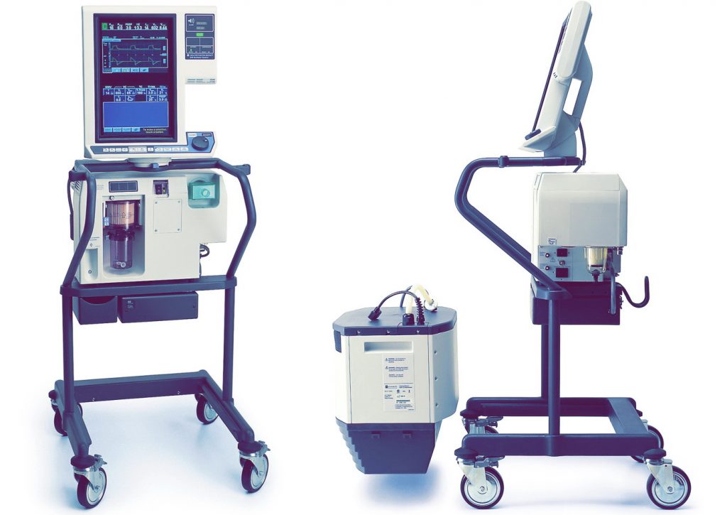
Аппарат искусственной вентиляции легких npb 840 разработан для управления дыханием. Предлагаются различные режимы вентиляции, а также подсказки врачу для выбора наиболее подходящих настроек вентилятора. Интерфейс пользователя рассчитан на любого, кто знаком с принципами работы вентилятора и предполагает минимальные сроки обучения пользователей. Интерфейс пользователя включает в себя сенсорные экраны DualView™, на которых отображаемые данные выводятся отдельно от настроек вентилятора, что позволяет быстро оценить состояние пациента. Производитель компания Nellcor Puritan Bennett США.
Также интерфейс включает область SandBox™, которая позволяет просмотреть настройки перед тем, как примененить их к пациенту. Программируемая стратегия управления тревогами SmartAlert™ разработана для предоставления специальной информации о причине возникновения тревоги и рекомендуемых действиях.
Puritan Bennett 840 ЦПУ
В вентиляторе npb 840 используются два независимых центральных процессора (ЦПУ): один обслуживает блок обеспечения дыхания (БОД), а другой используется для графического интерфейса пользователя (ГИП). Процессор БОД обеспечивает дыхание в соответствии с заданными переменными и проводит исчерпывающие фоновые тесты. Процессор ГИП принимает настройки вентиляции и тревог, а также контролирует работу вентилятора и процесс его взаимодействия с пациентом. ГИП определяет, правильно ли работает процессор БОД, а также предотвращает любой сбой, который может повлечь за собой сбой в работе функций контроля и отображения.
Puritan Bennett 840 ПДКВ
Вентилятор 840 обеспечивает принудительные или спонтанные дыхания с предварительной установкой уровня ПДКВ (положительного давления конца выдоха), чувствительности триггера, а также концентрации кислорода. Принудительное дыхание может контролироваться по давлению или объему, за исключением дополнительного режима BiLevel, в котором оно всегда контролируется только по давлению. При спонтанном дыхании (с поддержкой давлением или без нее) поток вдоха пациента достигает 200 л/мин.
Компрессор 804
Компрессор 804 (опция) поставляет сжатый воздух в БОД и может использоваться вместо стационарной системы подачи воздуха или баллонов с воздухом. Электропитание компрессора обеспечивается от БОД через коммуникационные кабели.
Источник резервного питания (ИРП) 802
Источник резервного питания (ИРП) 802 обеспечивает постоянным током блок обеспечения дыхания (БОД) и графический интерфейс пользователя (ГИП) в случае отсутствия переменного тока. Новый, полностью заряженный ИРП обеспечивает работу вентилятора (без компрессора или увлажнителя) как минимум на 30 минут. Таким образом, ИРП может обеспечить питание вентилятора при его транспортировке в пределах больницы.
Техническое описание Puritan Bennett 840
Используя сенсорный экран, регулятор и клавиши, расположенные на ГИП, врач передает вентилятору инструкции и данные. Процессор ГИП обрабатывает эту информацию и сохраняет ее в памяти вентилятора. Процессор БОД использует эту сохраненную информацию для контроля и наблюдения за потоками газа к пациенту и обратно. Любая новая информация о настройках передается между процессорами БОД и ГИП в четыре этапа (с проверкой на каждом этапе). Также каждый процессор осуществляет непрерывный фоновый контроль целостности настроек.
Чтобы ГИП мог контролировать работу БОД, последний регистрирует и записывает следующие исходные сигнальные данные для пересылки в ГИП: давление вдоха, давление выдоха, ток в клапане выдоха, а также в кислородных и воздушных клапанах вдоха. БОД также посылает следующую информацию по настройкам и дыханию в ГИП: верхний предел давления в контуре, фазу дыхательного цикла, режим дыхания, смещение автообнуления, время вдоха, интервал апноэ, целевое давление для дыхания с контролем по давлению, начало фазы дыхательного цикла и отметку времени.
Схема блока вентилятора Puritan Bennett 840
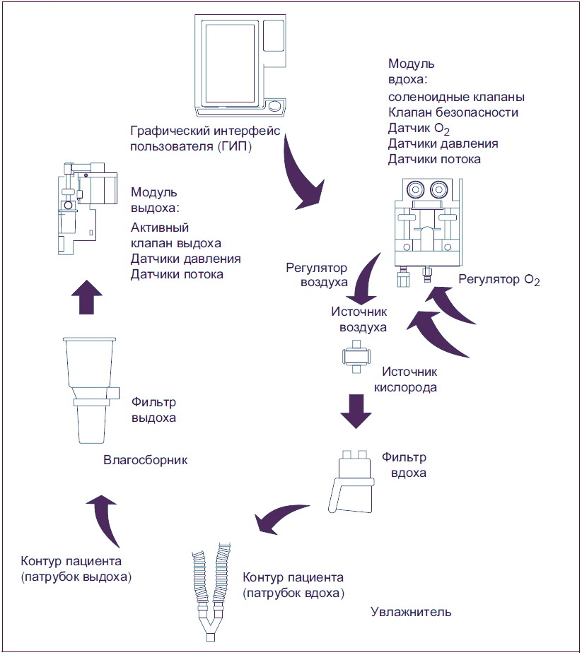
ГИП записывает событие в журнал диагностики и переводит аппарат ивл пуритан беннет 840 в нерабочее состояние при следующих условиях:
- Искажены любые исходные сигнальные данные из трех передач БОД за 24 часа.
- ГИП не получает данных от БОД в течение установленного времени.
- ГИП определяет, что исходные сигнальные данные корректны, но пределы настроек и тревог обрабатываются неверно.
Триггер по давлению
Для выявления дыхательных усилий пациента, аппарат ИВЛ Puritan Bennett 840 использует триггер по потоку или давлению. Когда выбран триггер по давлению, вентилятор контролирует давление в контуре пациента. Как только пациент вдыхает газ из контура и давление в дыхательных путях падает по крайней мере до выбранного значения чувствительности по давлению, вентилятор производит вдох.
Триггер по потоку
Когда выбран триггер по потоку (Flow-by™), аппарат ИВЛ npb 840 отслеживает разницу между значениями потока вдоха и выдоха, измеренными с помощью датчика. Если пациент делает вдох, вентилятор обнаруживает снижение потока выдоха, в то время как поток вдоха остается неизменным, и разница между потоками вдоха и выдоха увеличивается. Когда разница достигает заданного оператором значения для чувствительности по потоку, вентилятор Puritan Bennett 840 производит вдох.
Если пациент не осуществляет вдох, любая разница между доставленным потоком и потоком выдоха является следствием погрешности датчиков или утечек в контуре пациента. Чтобы компенсировать утечку в контуре пациента, которая может привести к автозацикливанию, оператор может увеличить настройку чувствительности по потоку.
Резервный метод включения вдоха
В качестве резервного метода включения вдоха также используется настройка чувствительности по давлению в 2 смH2O. Эта настройка является достаточно чувствительной, чтобы переключение могло осуществляться приемлемым усилием пациента, и в то же время позволяет избежать автозацикливания.
Воздух и кислород из баллонов, стационарной системы подачи воздуха или компрессора (только воздух) подаются в вентилятор через шланги и коннекторы (имеется несколько моделей коннекторов). Поступив в вентилятор, воздух и кислород подаются под должным давлением и смешиваются в соответствии с выбранным процентом O2.
Модуль вдоха
Аппарат искусственной вентиляции легких npb 840 подает смесь воздуха и кислорода через модуль вдоха к пациенту. С помощью гальванического кислородного датчика отображается концентрация кислорода в дыхательной смеси.
Гальванический датчик генерирует напряжение пропорционально концентрации кислорода. ИВЛ подает сигнал тревоги, если отображаемая концентрация кислорода на 7% больше или меньше настройки процента O2, или меньше 18%.
В магистрали вдоха также имеется клапан безопасности, при необходимости используемый для снижения давления (например, если контур пациента перекручен или закупорен). Оператор выбирает тип увлажнения, используемый вентилятором для коррекции температуры газа и влажности.
Дыхательная пневматика Puritan Bennett 840
Дыхательная пневматика вентилятора состоит из двух параллельных контуров: кислородного и воздушного. Основными элементами дыхательной пневматики являются два пропорциональных соленоидных клапана (PSOL), контролирующих поток газа, доставляемый пациенту.
Кислородные и воздушные датчики потока, наряду с сигналами давления из контура пациента, обеспечивают обратную связь, используемую процессором БОД для контроля работы соленоидных клапанов. В результате аппарат ИВЛ npb 840 обеспечивает пациента дыхательной смесью в соответствии с заданными врачом переменными. Смесь воздуха и кислорода поступает к пациенту через внешний контур.
Контур пациента
Контур пациента включает внешние компоненты, обеспечивающие циркуляцию газа между вентилятором и пациентом. К этим компонентам относятся: фильтр вдоха (защищает от инфицирования газ, проходящий между пациентом и вентилятором), увлажнитель, патрубки вдоха и выдоха контура пациента (воздуховод, в котором циркулирует газ), влагосборник (защищает систему выдоха от конденсата, содержащегося в выдыхаемом газе) и фильтр выдоха (препятствует загрязнению вентилятора и попаданию бактерий, содержащихся в выдыхаемом пациентом газе, в комнатный воздух).
Клапан выдоха
Аппарат искусственной вентиляции легких (ИВЛ) npb 840 постоянно контролирует клапан выдоха, работа которого точно определяется программой на протяжении фаз вдоха и выдоха. Клапан выдоха позволяет вентилятору обеспечивать интенсивное дыхание, сводя к минимуму превышения давления, контролируя ПДКВ и уменьшая избыточное давление. Система выдоха контролирует газ, поступающий из контура пациента для спирометрии.
На протяжении всего дыхательного цикла преобразователи давления контролируют давление вдоха, выдоха и атмосферное давление. Выдыхаемый газ нагревается до температуры выше точки росы, чтобы предотвратить образование конденсата в магистрали выдоха.
Источник электропитания Puritan Bennett 840
Вентилятор питается от сети переменного тока или от источника резервного питания. Источник электропитания вентилятора сконструирован таким образом, чтобы обеспечить защиту от колебаний напряжения, температуры или перегрузок по току. Фиксатор шнура питания предотвращает случайное отсоединение от источника питания. Крышка на переключателе мощности предохраняет от сбоев в электросети и случайного отключения питания.
ИВЛ Puritan Bennett 840 содержит источник резервного питания (ИРП) 802, который снабжает его постоянным током в случае отсутствия переменного. Полностью заряженный ИРП при нормальных внешних условиях может обеспечивать вентилятор электропитанием не менее 30 минут (ИРП не обеспечивает питанием компрессор). Перезарядка ИРП происходит при работе от электросети. ГИП указывает на то, что аппарат ИВЛ работает от ИРП.
Аварийные ситуации
К аварийным ситуациям относятся: нерабочее состояние и клапан безопасности открыт (КБО). Нерабочее состояние вентилятора всегда включает состояние КБО, однако состояние КБО не всегда указывает на нерабочее состояние вентилятора.
Нерабочее состояние
Вентилятор сигнализирует о нерабочем состоянии в случае аппаратного сбоя или критической ошибки в программном обеспечении, которая может привести к нарушению безопасности вентиляции. Когда вентилятор находится в нерабочем состоянии, зажигается индикатор нерабочего состояния и вентилятор переходит в состояние КБО.
Для возобновления работы вентилятор необходимо отключить, затем снова включить. При повторном включении сервисный инженер должен провести полный внутренний тест (ПВТ). Перед тем как продолжить нормальную вентиляцию необходимо в обязательном порядке провести ПВТ.
Клапан безопасности открыт (КБО)
Когда аппарат ИВЛ Puritan Bennett 840 находится в состоянии КБО, клапан безопасности позволяет пациенту дышать атмосферным воздухом без помощи вентилятора. Аппарат ИВЛ будет оставаться в состоянии КБО до тех пор, пока не будет ликвидирована причина этого состояния, либо, если вентилятор находится в нерабочем состоянии, – пока автоматический внутренний тест при включении питания (АВТ) не подтвердит наличие электропитания и нормальное функционирование главных электронных систем.
Если аппарат ивл пуритан беннет 840 переходит в состоянии КБО, загорается индикатор состояния клапан безопасности открыт и звучит сигнал тревоги высокого приоритета. Вентилятор переходит в состоянии КБО, если возникает сбой аппаратуры или программного обеспечения (который может привести к нарушению безопасности вентиляции), при отсутствии подачи воздуха и кислорода или при обнаружении окклюзии.
В случае неисправности, препятствующей открытию клапана безопасности, существует также аналоговая цепь, открывающая клапан безопасности, когда системное давление превышает 100 – 120 смH2O.
Интерфейс Puritan Bennett 840
Аппарат ИВЛ npb 840 оснащен графическим интерфейсом пользователя (ГИП), рассчитанным на интуитивное понимание принципов обращения с ним врачами, осуществляющими вентиляцию.
Графический интерфейс пользователя
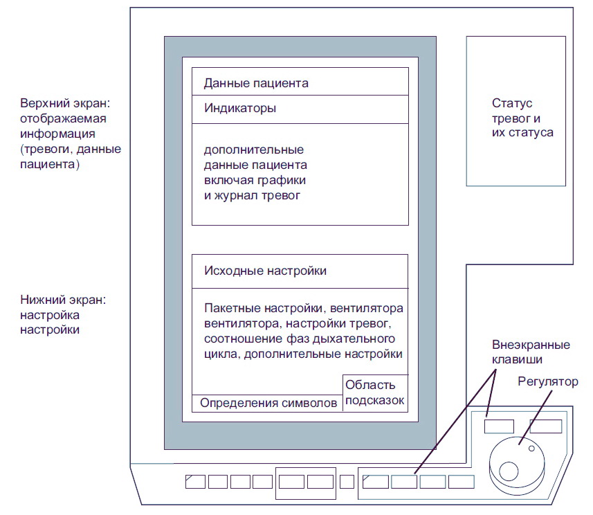
Подключение источников воздуха и кислорода
Аппарат ИВЛ Puritan Bennett 840 может использовать воздух и кислород из баллонов или из стационарной разводки. Чтобы подключить источники воздуха и кислорода, выполните следующие действия:
- Убедитесь в том, что давление подачи находится в пределах 35-100 psi (241-690 кПа).
- Присоедините шланги от источников к входным разъемам на задней стенке вентилятора.
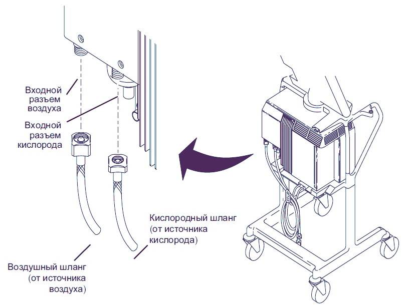
Сборка контура пациента
На рисунке ниже показано, как смонтировать контур пациента, включая фильтр вдоха, увлажнитель (если используется), патрубок вдоха, тройник пациента, патрубок выдоха, влагосборник и фильтр выдоха.
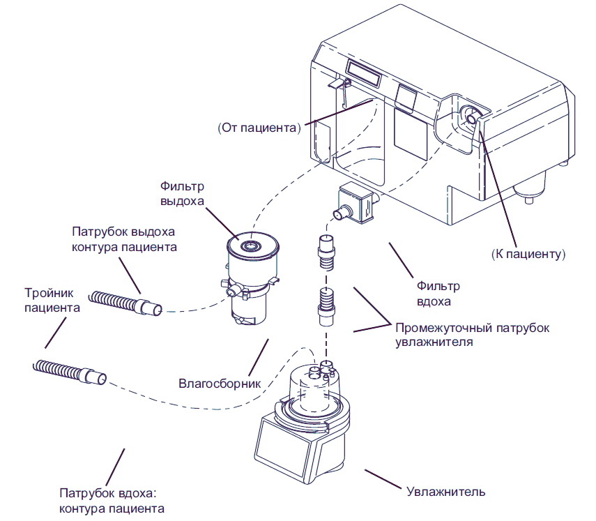
Выполнение короткого внутреннего теста (КВТ)
Короткий внутренний тест (КВТ) – это короткая (около 3 минут) и простая последовательность тестов, которая проверяет правильность функционирования вентилятора, контур пациента (включая трубки, увлажнитель и фильтры) на утечки и измеряет комплайнс контура. Тест КВТ также проверяет сопротивление фильтра выдоха.
Компания Nellcor Puritan Bennett рекомендует выполнять КВТ каждые 15 дней в перерывах между обслуживанием пациентов, и каждый раз при изменении контура пациента.
Очистка, дезинфекция и стерилизация Puritan Bennett 840
Чтобы обеспечить правильное функционирование вентилятора, выполняйте следующие процедуры по техническому обслуживанию в рекомендованные интервалы времени.
Очистка
Нельзя чистить или повторно использовать индивидуальные или одноразовые принадлежности. Для чистки принадлежностей не используйте жесткие щетки или другие инструменты, которые могли бы повредить их поверхность.
- Промойте принадлежности мягким мыльным раствором и теплой водой.
- Тщательно промойте принадлежности в чистой теплой воде (допускается использование водопроводной воды) и вытрите насухо.
- Компания Nellcor Puritan Bennett рекомендует проверять все принадлежности при каждой очистке. Заменяйте любые поврежденные компоненты.
- Всякий раз, когда вы используете новые принадлежности в вентиляторе, запускайте внутренние тесты.
Стерилизация в автоклаве
Перед автоклавированием отделите компоненты друг от друга и заверните каждый из них в марлю или аналогичный ей материал. Эффективная стерилизация проходит в паровом автоклаве при 132 °C (270 °F) в течение 20 минут при повышенном давлении. Следуйте инструкциям производителя парового стерилизатора. Выполните следующие действия:
- Разберите;
- Очистите;
- Проверьте;
- Соберите;
- Стерилизуйте;
- Запустите КВТ.
Пастеризация
Поместите компоненты в пастеризатор, нагретый до температуры 76-79 °C (169-174 °F) на 30 мин. Выполните следующие действия:
- Разберите;
- Очистите;
- Проверьте;
- Соберите;
- Стерилизуйте;
- Запустите КВТ.
Химическая дезинфекция
Погрузите принадлежности в дезинфицирующий раствор в соответствии с инструкциями производителя. К допустимым дезинфицирующим веществам относятся следующие вещества и их эквиваленты: нашатырный спирт (15% раствор), Amphyl, хлорная известь (10% раствор), Cavicide, Cidex, Control III и изопропиловый спирт (70% раствор). Выполните следующие действия:
- Разберите;
- Очистите;
- Проверьте;
- Соберите;
- Стерилизуйте;
- Запустите КВТ.
Техническое обслуживание Puritan Bennett 840
Ниже указаны периодичность и процедуры технического обслуживания. Информацию об общей часовой выработке вентилятора и компрессора смотрите на Информационном экране вентилятора.

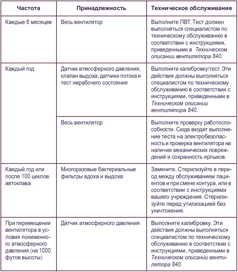
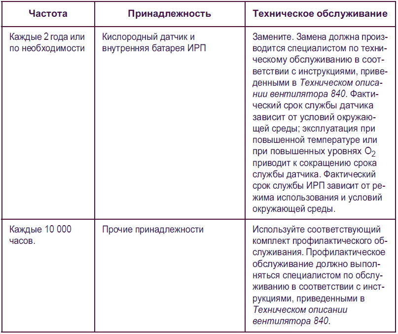
Технические характеристики Puritan Bennett 840
Ниже указаны технические характеристики аппарата ИВЛ Puritan Bennett 840.
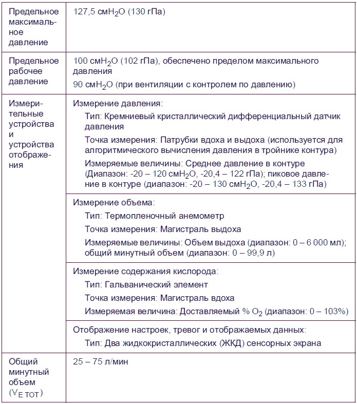
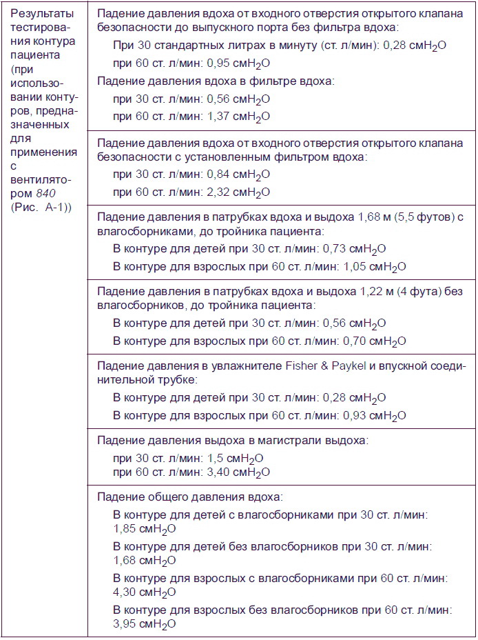
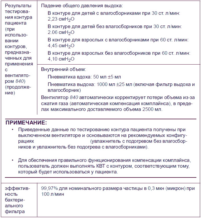
Скачать инструкцию на аппарат ИВЛ Puritan Bennett 840
Скачать инструкцию и другую документацию на аппарат искусственной вентиляции легких можно здесь.
Руководство пользователя ( user manual ) на русском языке ИВЛ Puritan Bennett 840 скачать.
Регистрационное удостоверение ИВЛ Puritan Bennett 840 скачать.
Так же смотрите ИВЛ фаза 5 01, ИВЛ Evita XL Drager.