- Manuals
- Brands
- RadioLink Manuals
- Remote Control
- AT9
- Instruction manual
-
Contents
-
Table of Contents
-
Bookmarks
Quick Links
RADIOLINK AT9
(Dsss)
INSTRUCTION MANUAL
RADIOLINK ELETRONIC LIMITED
Technical updates and additional programming examples available at:
http://www. radiolink.com.cn
Related Manuals for RadioLink RADIOLINK AT9
Summary of Contents for RadioLink RADIOLINK AT9
-
Page 1
RADIOLINK AT9 (Dsss) INSTRUCTION MANUAL RADIOLINK ELETRONIC LIMITED Technical updates and additional programming examples available at: http://www. radiolink.com.cn… -
Page 2
More information please check our website as below: http://www.radiolink.com.cn Support and Service: It is recommended to have your Radiolink equipment serviced annually during your hobby’s “off season” to ensure safe operation. Please feel free to browse our GUEST BOOK for assistance in operation, use and programming. Please be sure to regularly visit the Service and Support web site at www.radiolink.com.cn. -
Page 3
Note:About flying While you are getting ready to fly,if you place your transmitter on the ground ,be sure that the wind won’t tip it over. If it is knocked over, the throttle stick may be accidentally moved, causing the engine to speed up. Also, damage to your transmitter may occur. Other than 2.4GHz system: Before taxiing, be sure to extend the transmitter antenna to its full length.collapsed antenna will reduce your flying range and cause a loss of control.It is a good idea to avoid pointing the transmitter antenna directly at the model, since the signal is weakest in that direction. -
Page 4: Table Of Contents
TABLE OF CONTENTS Part 1. INTRODUCTION OF AT9 SYSTEM…………….5 1.1.1 Function of transmitter………………….5 1.1.2 Transmitter Panel Shows:………………… 6 1.1.3 Receiver:R9D……………………7 RADIO INSTALLATION………………….7 1.2.1 Guidelines to mount the servos, receiver and battery…………… 7 1.2.2 Receiver and servo connections………………..9 1.2.3 Installment of antenna………………….11 RADIO BASIC SETTING………………….11 1.3.1 Basic setting of the transmitter……………….
-
Page 5
3.3.15 THROTTLE-NEEDLE mixing (ACRO/ HELI):…………48 PART 4 GLIDER MODEL FUNCTIONS……………… 51 SET BASIC MENU OF GLID ………………..51 SET GLID TYPE ……………………52 GLID ADVANCE MENU ………………….53 4.3.1 AILE DIFF (FIND IN ACRO FUNCTION MENU 3.3.5)……….53 4.3.2 FLAPERON (GLID 1A+1F, FIND IN ACRO FUNCTION MENU 3.3.3)……. 53 4.3.3 V-TAIL (FIND IN ACRO FUNCTION MENU 3.3.10)………….53 4.3.4… -
Page 6: Part 1. Introduction Of At9 System
Part 1 INTRODUCTION OF AT9 SYSTEM Note that in the text of this manual, begainning at this point, any time we are using a feature’s specialized name or abbreviation as seen on the screen of the AT9, that name, feature, or abbreviation will be exactly as seen on the radio’s screen, including capitalization and shown in a DIFFERENT TYPE STYLE for clarity,Any time we mention a specific control on the radio itself, such as moving SWITCH A, KNOB VR(B), or the THROTTLE STICK, those words will be displayed as they are here.
-
Page 7
SWITCH ASSIGNMENT TABLE • The factory default functions activated by the switches and knobs for a AT9 transmitter are… -
Page 8: Receiver:r9D
shown below. • Most AT9 functions may be reassigned to non-default positions quickly and easily. Always check that you have the desired switch assignment for each function during set up. Switch/Knob Airplane ( ACRO ) Sailplane/Glider Helicopter ( HELI ) Aircraft ( GLID ) A or H SWITCH A…
-
Page 9
If in doubt, please contact Radiolink aftersales or distributors for service. • Always mount the servos with the supplied rubber grommets.Don’t over tighten the screws.No part of the servo casing should contact the mounting rails,servo tray or any part of structure.Otherwise vibration will be… -
Page 10: Receiver And Servo Connections
1.2.2 Recervier and servo connections (1)Airplane servo connection Receiver output AIRPLANE and channel ailerons/aileron-1¹/combined flap-2&aileron-1¹ elevator throttle rudder spare/landing gear/aileron-2¹ ³/combined flap-1 and aileron-2² ³ spare/flaps/combined flap-1 and aileron-2² spare/aileron-2¹ spare/elevator-24/mixture control spare spare (2)Glider/Sailplane servo connction Glider GLID ( 1 A+ 1 F) Receiver output and channel…
-
Page 11
(3)Helicopter servo connection Receiver output Helicopter and channel aileron/cyclic roll Elevator/cyclic pitch Throttle Rudder Spare/gyro Pitch(collective pitch) Spare/governor spare/mixture control Spare spare The above listed receiver and channels is referred to the channel 1~9 of the receiver R9D, connect the receiver with the related servo, you can control the servos by the correspondent switch. -
Page 12: Installment Of Antenna
VCC INTERFACE GND INTERFACE 1.2.3 Installment of antenna (1) Installment of receiver antenna 1. The antenna must be kept as straight as possible. Otherwise it will reduce the effective range. 2. Large model aircraft may of some metal part interfering signal; in this case the antennas should be placed at both sides of the model.
-
Page 13: Model Type
Adjusting Display Contrast: To adjust the display contrast, from the home menu press and hold the END BUTTON. Turn the DIAL while still holding the END BUTTON: clockwise to brighten and counterclockwise to darken the display. User name setting: user name can be set by DIAL and PUSH with letters and numbers. Alarming voltage: Transmitter: preset 8.6V, can be self-set Receiver: preset 4.0V, can be self-set…
-
Page 14
Press and hold MODE BUTTON for one second to open programming menus. Press MODE BUTTON to switch between BASIC and ADVANCE. Press MODE BUTTON to scroll between conditions in certain functions. END BUTTON: Press END BUTTON to return to previous screen. Closes functions back to menus, closes menus to start-up screen. -
Page 15: Part 2. Basic Function Of Airplane
PART 2. BASIC FUNCTION OF AIRPLANE Pls pay attention that the (BASIC)menu is suitable for all type models(airplane, helicopter, glider,aircraft). The motor cut will be introduced in Glider (Basic )Menu,except Idle down &Throttle cut.Helicopter Basic Menu include some extra function (swashplate tilting,throttle and pitch curves and the tail totor anti torque mixing under normal flght model) will be discussed in Helicopter section.
-
Page 16
This guide is intended to help you acquainted with the radio, to give you some ideas and direction on how to do.We give you a big picture overview of what we accomplish; a ‘by name’ description of what we’re doing to help you with the radio; then a step-by-step instruction to leave out the mystery when setting up your model. -
Page 17: Airplane Basic Function
to MIX,press , to INH to SW,press , to SwC Activate,assign SWITCH and adjust. to POSI,press to DOWN , Close the function to RATE , press to down , position, throttle stick down until the throttle barrel closed From BASIC menu,choose the D/R,EXP to D/R,EXP,press SwA to up position A to CH,press…
-
Page 18
model name. Accordingly, if you want to change the model type, the whole data need to reset, also for model name. The first thing to copy is to change the model type or delete the original name and rename a new model to avoid confusion. -
Page 19: Model Type
•functions specially for aero basic: •snap roll •Elev-flap mix (twin Elevator Servos support) •oil power plane: idle down、throttle shut、throttle needle mix etc. •functions aero basic doesn’t have: 5 individual flight conditions (normal, start, speed, distance, landing) If the model type selected for glider or helicopter, please go to the related chapter for setting. After model type changed, all parameters need to reset, including name.
-
Page 20: End Point Of Servo Travel Adjustment (End Point, Also Called Epa)
As shown below, home screen will display plane type and throttle pitch: ILLUST: displays the illustration of helicopter in the home screen. (Default) THR/PIT: displays the current throttle and pitch position in the home screen. Step to change plane type image to thr/pit: under model type helicopter, enter basic menu, choose MODEL TYPE, and enter HOME DISP, press PUSH, then DIAL to THR/PIT, then press PUSH.
-
Page 21: Trim
THROTTLE DELAY. Goals Steps Inputs for 1s.(If ADVANCE, again) Open END POINT function Decrease the flap servo to END POINT,PUSH throw in the upward Choose proper channel and move direction to 5% to allow stick or Knob in direction you trimming of level flight to FLAP,PUSH,…
-
Page 22: Sub Trim
SUB-TRIM: makes small changes or corrections to the neutral position of each servo. Range is -120 to +120, with 0 setting, the default, being no SUB-TRIM. We recommend that you center the digital trims before making SUB-TRIM changes, and that you try to keep all of the SUB-TRIM values as small as possible.
-
Page 23: Dual/Triple Rates And Exponential (D/R,Exp)
Goals Steps Inputs for 1s .(If ADVANCE again) Open REVERSE function to REVERSE, PUSH. Revers the direction to REV,’Are you sure? displays Choose proper channel and to ELEV, of the elevator set direction(Ex:ELEV REV)] for 1s。 servo. Close 2.3.7 Dual/triple rates and exponential (D/R,EXP) Dual/Triple Rates: reduce/increase the servo travel by flipping a switch, or (ACRO GLID) they can be engaged by any stick position.
-
Page 24
• Range: 0 — 140% (0 setting would deactivate the control completely.) Initial value=100% • Adjustable for each direction (ACRO/ GLID) (ie. Up/down, left/right) (Ex: Most models fly upright without any elevator trim, but require some down elevator when inverted just to maintain level flight. By increasing the down travel by the amount required to hold the model inverted, the model now has equal travel available from level upright or level inverted. -
Page 25: Throttle Cut
to SW,PUSH. to Cond. Optional:assign dual rates to Repeat steps above to adjust for each condition. have one for each condition. Goals Steps Inputs Open D/R,EXP for 1s to BASIC( to D/R,EXP,PUSH. Choose channel to change to CH,PUSH, to AILE,PUSH (Ex:aileron is already selected) Optional:Change switch position.
-
Page 26
(with THROTTLE STICK at idle). The movement is largest at idle and disappears at high throttle to avoid accidental dead sticks. In HELI, there is an additional setting. The switch’s location and directio must be chosen. It defaults to NULL to avoid accidentally assigning it to a switch, which might result in an unintentional dead stick in flight. -
Page 27: Idle Down (Acro Only)
HELICOPTER This function is used to stop engine after flight is finished. You can set engine powered on/ off, without shifting trim stick to power off and set again every time before flight. Throttle shut for helicopter includes THR ON/ OFF (position above idle down). Before resetting throttle cut, throttle stick must keep below setting point to avoid a sudden speeding up.
-
Page 28: Auxiliary Channel Function (Including Channel 9-10 Controls)
【F/S】 1:AILE NOR 2:ELEV NOR 3:THRO 15% 4:RUDD NOR CH1:AILE 5:GEAR NOR NOR F/S 6:FLAP NOR 7:AUX1 NOR 8:AUX2 NOR Adjustability: •Each channel may be set independently. • The NOR (normal) setting holds the servo in its last commanded position. •…
-
Page 29: Timer Submenu (Stopwatch Functions)
direction may be changed. • multiple channels may be assigned to the same switch, slider or knob; • channels set to «NULL» are only controlled by mixes. (Ex: utilizing 2 channels for 2 rudder servos. See mixes, p. 68.) • If GYRO SENSE, GOVERNOR, and THR-NEEDLE functions are activated, AUX-CH settings of related channels become invalid automatically.
-
Page 30: Trainer
Adjustability: • Count down timer: starts from the chosen time, displays time remaining. If the time is exceeded, it continues to count below 0. • Count up timer: starts at 0 and displays the elapsed time up to 99 minutes 59 seconds. •…
-
Page 31: Logic Switch Selection (Logic Sw)
• SWITCH: controlled by spring-loaded SWITCH H only. Not assignable. • Compatibility: The AT10 may be master or student with any Radiolink transmitter compatible with the cord. Simply plug the optional trainer cord (For AT10 series, sold separately) into the trainer connection on each transmitter, and follow the guidelines below.
-
Page 32: Servo Display And Cycle Submenu
Adjustability: • Three logic switches can be used. (LSW1, LSW2, and LSW3 ) • SW(1): Any SWICH A-H or THRSTKS, SW(2): Any SWICH A-H • Switch position (POSI) • Logic mode: AND or OR (MODE) 2.3.15 SERVO display and cycle submenu: Displays radio’s output to channels 1-10.
-
Page 33
Find telemetry information: under BASIC MENU, select RECEIVE, press PUSH to enter, you can find the telemetry info, shown as below. RX is receiver voltage, EXT is external voltage. Also temperature and engine speed (EXT, TEMPERATURE, RPM, and GPS all need telemetry sensor). RSSI is signal strength, NULL is for no signal, and 0 is for max. -
Page 34: Part 3. Acro Advance Menu Functions
Part 3. ACRO ADVANCE MENU FUNCTIONS 3.1 AIRPLANE WING TYPES (ACRO/GLID): There are 3 basic wing types in aircraft models: • Simple. Model uses one aileron servo (or multiple servos on a Y-harness into a single receiver channel) and has a tail. This is the default setup and requires no specialized wing programming. •…
-
Page 35: Acro Advance Function Menu
channel CH6&5 Select AILE-2 and change to to AILE-2. to CH6&5 CH6&5. Allow twin aileron servo operatin with a 5-channel Close receiver. There are 4 basic tail types in aircraft models: • Simple. Model uses one elevator servo and one rudder servo (or multiple servos on a Y-harness). This is the default.
-
Page 36: Program Mix
• THROTTLE DELAY mixing is a pre-programmed delay mix that slows down the response of the CH3 servo. Next, we’ll get an in-depth look at some pre-programmed mixes (mixes whose channels are predefined for simplicity) we’ve not covered yet, and last, look at the fully-programmable mix types. 3.3.1 Program MIX AT9 contains four separate linear programmable mixes.
-
Page 37
MASTER SLAVE LINK TRIM SWITCH POSITION RATE OFFSET VR(D) THRO NULL •Slave: the controlled channel. The channel is moved automatically in response to the movement of the master channel. The second channel is in a mix’s name (i.e. aileron-to-rudder). •Link: Link this programmable mix with other mixes. Ex: PMIX FLAP-ELEVATOR mixing to correct for ballooning when flaps are lowered, but model has a V-tail. -
Page 38: Curve Programmable Mixes (Prog.mix5-8)(Heli: Prog.mix5-6 )
Optional:set Master as OFST or to Master,PUSH, todesiredchoice VR(A-E) Set LINK and TRIM as needed. to LINK,PUSH , to DWON Assign SWITCH and position. to SW,PUSH, to SwC (Ex:change from E to C,Down) to POSI,PUSH to DOWN to SW ,PUSH to STK-THR Optional:set switch to STK-THR to activate mix with THROTTLE…
-
Page 39: Flaperon (Acro/Glid 1A+1F )
• ACRO/GLID Defaults: The 4 programmable curves mixes default to the most frequent choices, but can be set to any channel. • PROG.MIX5 rudder-to-aileron for roll coupling compensation (GLID mixes default to aileron-to-elev.) • PROG.MIX6 rudder-to-aileron for roll coupling compensation (GLID mixes default to aileron-to-elev.) •…
-
Page 40: Flap-Trim
The FLAPERON mixing function uses one servo on each of the two ailerons, and uses them for both aileron and flap function. For flap effect, the ailerons raise/lower simultaneously. Of course, aileron function (moving in opposite directions) is also performed. Note: When changing the polarity of a rate, «change rate dir?»…
-
Page 41: Aile Diff (Acro/ Glid 2A+1F/ Glid 2A+2F)
ACRO GLID FLAP-TRIM assigns the primary flaperon control [defaults to VR(A)] to allow trimming in flight of the flap action of flaperons. Note: Even if FLAP-TRIM is made active with AIL-DIFF, it will not have any effect. The ONLY function that allows control of the ailerons as flaps in the AIL-DIFF configuration is AIRBRAKE. Most modelers use AIRBRAKE, or programmable mixes, to move the flaps to a specified position via movement of a switch.
-
Page 42: Air Break (Acro/ Glid)
Activate twin aileron to BASIC menu, again to ADVANCE Open the FLAPERON. servosusing AILE-DIFF. to AILE-DIFF .PUSH. Note that the function defaults to no difference in Activate the function. to MIX,PUSH. to ACT down travel vs. up travel. If Optional:adjust the up/down you want differential travel, to AILE1 AILERON STICK.
-
Page 43: Elev-Flap Mixing (Acro/Glid)
CH1 and CH6. The flap choice has no effect on the flaperons. • If AIL-DIFF is active, then CH1 and CH7 may be independently adjusted. • Normally both ailerons are raised equally in AIRBRAKE, and the elevator motion is set to maintain trim when the ailerons rise.
-
Page 44: Dual Elevator Servos (With A Rudder) (Ailevator) (Acro)
Adjustability: • Rate: -100% (full up flap) to +100% (full down flap), with a default of +50% (one-half of the flap range is achieved when the ELEVATOR STICK is pulled to provide full up elevator.) • Switch: fully assignable. Also LOGIC SW (Lsw1 to 3) may be assigned. IF you set it to NULL, the mix does not work.
-
Page 45: Snap Rolls (Acro)
Once AILEVATOR is activated, unless you zero out the aileron figures (see below), any time you move your ailerons or any programming moves your ailerons (ie. RUDDER-AILERON mixing), the radio automatically commands both elevator servos to also operate as ailerons. To deactivate this action, simply set the 2 aileron travel settings to 0 in the AILEVATOR function.
-
Page 46: V-Tail (Acro/ Glid)
• ON: the safety mechanism is activated when the landing gear SWITCH is in the same position as at the time this feature is changed to ON. Snap rolls will not be commanded even if the snap roll SWITCH is turned on with the gear SWITCH in this position.
-
Page 47: Elevon
large value of travel is specified, when the sticks are moved at the same time, the controls may bind or run out of travel. Decrease the travel until no binding occurs. Adjustability: • Requires use of CH2 and CH4. • Independently adjustable travels allow for differences in servo travels. •…
-
Page 48: Gyro Sense
Adjustability: • Plug the gyro’s sensitivity adjustment to channel 5, 7, or 8 of the receiver. (selectable) • Full switch assignable (SWITCH A-H) • Each rate setting may be set from 0 to NOR100% or AVC100% gain. NOR: GY mode gain. AVC: STD mode gain •…
-
Page 49: Thr-Delay (Acro)
The THR-DELAY function is used to slow the response of the throttle servo to simulate the slow response of a turbine engine. A 40% delay setting corresponds to about a one-second delay, while a 100% delay takes about eight seconds to respond. This function may also be used to create a “slowed servo” on a channel other than throttle.
-
Page 50: Throttle-Needle Mixing (Acro/ Heli)
Optional: delete the curve to P3 (-stk-). for 1sec.to delete the curve point. point.And return the curve to P3 (-stk-), for 1sec.to return point.(Ex:point 3) Adjust the next point. Repeat as needed. Close 3.3.15 THROTTLE-NEEDLE mixing (ACRO/ HELI): ACRO HELI THROTTLE-NEEDLE is a pre-programmed mix that automatically moves an in-flight mixture servo (CH8) in response to the THROTTLE STICK inputs for perfect engine turning at all throttle settings.
-
Page 51
to PIONT. Throttle Stick to P 1, to40%, Adjust the travels as needed to match your engine by slowly Throttle Stick to P 2, to 45%, moving the stick to each 5 points, then adjusting the percentage at Throttle Stick to P 3, to 65%,… -
Page 52: Part 4 Glider Model Functions
PART 4 GLIDER MODEL FUNCTIONS Please note that nearly all of the BASIC menu functions are the same for airplane (ACRO setup), sailplane (GLID 1A+1F/ 2A+1F/ 2A+2F setups), and helicopter (HELI setups). The features that are identical refer back to the ACRO chapter. The glider BASIC menu includes MOTOR CUT and does not include IDLE-DOWN or THR-CUT.
-
Page 53: Set Glid Type
In the BASIC menu, open to REVERSE. REVERSE. REVERSE servos as needed for Choose desired servo and to 4.RUDD, REV is highlighted. for 1 proper control operation. reverse its direction of sec. ‘Are you sure?’Displays. to confirm. travel. (Ex:reverse rudder servo.) To BASIC menu.
-
Page 54: Glid Advance Menu
Before doing anything else to set up a glider or sailplane, first you must decide which MODEL TYPE best fits your aircraft. • GLID(1A+1F): The GLID (1A+1F) MODEL TYPE is intended for sailplanes with one or two aileron servos (or none), and a single flap servo (or two connected with a y-connector). This TYPE is meant to be a very simplistic version to set up a basic glider without a lot of added features.
-
Page 55: Flaperon (Glid 1A+1F, Find In Acro Function Menu 3.3.3)
4.3.1 AILE DIFF (FIND IN ACRO FUNCTION MENU 3.3.5) 4.3.2 FLAPERON (GLID 1A+1F, FIND IN ACRO FUNCTION MENU 3.3.3) 4.3.3 V-TAIL (FIND IN ACRO FUNCTION MENU 3.3.10) 4.3.4 OFFSET (GLID 2A+2F): Additional flight conditions are available specifically for sailplanes. These additional flight conditions contain different offset trims to make the sailplane perform certain maneuvers more easily.
-
Page 56: Chamber-Flp
Close 4.3.5 START DELAY (GLID 1A+1F only): START DELAY automatically switch the offset trims (OFFSET) from the START condition’s trims to the normal condition’s trims after proceeding the delay time (max.10sec.) which is set by the -dly- item when activating the START condition. (It is convenient for hand launch glider.) Note: The same delay amount for elevator and rudder is recommended when using V-tail function.
-
Page 57: Camber Mixing
Note: When changing the polarity of a rate, «change rate dir?» is displayed for a check. Please set up after pressing DIAL for 1 second and canceling an alarm display. Goals Steps Inputs to BASIC . again to ADVANCE Open the CAMBER FLAP to CAMBER-FLP, function.
-
Page 58: Butterfly (Crow) Mixing
to PRE , VrA to desired Set the reference point. point for 1 sec. Close 4.3.8 BUTTERFLY (crow) mixing BUTTERFLY simultaneously moves the flaps, twin ailerons and elevator, and is usually used to make steep descents or to limit increases in airspeed in dives. Separate two BUTTERFLY settings are available. (CRI1/CRI2) ADJUSTABILITY: •…
-
Page 59: Aile/ Rudd Mix
to BASIC . again to ADVANCE Open the BUTTERFLY function to BUTTERFLY, Activate BUTTERFLY. Adjust the aileron and flap travel to 75% SWA to UP position Activate the function to MIX to OFF , Elevator setting are adjustable in the Adjust the travels as B.FLY-ELE.
-
Page 60: Spoiler Mix (Glid)
This pre-programmed mix is used to create full span aileron action on a glider with 4wing servos. This increases the roll rate and decreases induced drag. For normal flying, a value of about 50% is often used. For slope racing or F3B models in speed runs, you may wish to use a larger value approaching 100%.
-
Page 61: Flap-Trim (See Glid 3.3.4)
Adjust the spoiler Activate the function. to MIX , to ON. servo position to 60% Assign the SPO2-CH.(Ex: to –SPO2- CH to CH3, , CH3) Adjust the spoiler servo to –SPO1-POSI to -50%, to 60%, , position. (Ex: to –SPO2-POSI to +50%, to 60%, ,…
-
Page 62: Part. 5 Helicopter Model Functions
Part. 5 HELICOPTER MODEL FUNCTIONS Please note that nearly all of the BASIC menu functions are the same for airplane (ACRO setup), sailplane (GLID setups), and helicopter (HELI) setups. The features that are identical refer back to the ACRO chapter. 5.1 BASIC SETTING WITH HELICOPTER This guideline is intended to help you set up a basic (H-1) heli, to get acquainted with the radio, to give you a jump start on using your new radio, and to give you some ideas and direction on how to do even more…
-
Page 63
Input name. to change the first character. Close the submenu when When proper character is display. to next. Repeat. done. Goals Steps Inputs Reverse servos as needed for In BASIC menu, open for 1s to BASIC.(If proper control operation.Ex: Reverse. ADVANCE again) . -
Page 64: Heli-Specific Basic Menu Functions
With radio on, move helicopter’s tail to the right by hand. The gyro should give right rudder input (leading edge of the tail rotor Confirm gyro direction. blades move left). If the gyro gives the opposite input, reverse direction on the gyro unit itself. Goals Steps Inputs…
-
Page 65: Swash Plate Types
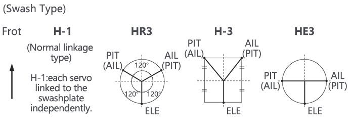
5.2.1 Swash Plate Types Goals Steps Inputs Confirm you are using On home screen,check model name and # on top left. If it is the proper model not the correct model (Ex:3) see MODEL SEL. Change the model memory(Ex:3) type and swashplate of model#3 from for 1s to BASIC.(If ADVANCE again) .
-
Page 66: Heli-Specific Advance Menu Functions
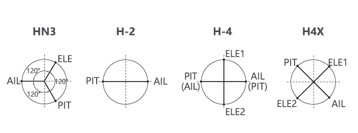
Swash plate function rate settings (SWASH AFR) reduce/increase/reverse the rate (travel) of the aileron, elevator (except H-2) and collective pitch functions, adjusting or reversing the motion of all servos involved in that function, only when using that function. Since these types utilize multiple servos together to create the controls, simply adjusting a servo’s REVERSE or END POINT would not properly correct the travel of any one control.
-
Page 67: Revo Mix
• Normal: Collective pitch curve that results in points 1, 4 and 7 providing .4, +5, (+8 to +10)* degrees pitch. A throttle curve setting of 0, 25, 36, 50, 62.5, 75, 100%. • Idle-ups 1 & 2: Idle-ups 1 and 2 are typically the same except for the gyro settings, with one being heading-hold/AVCS and the other being normal mode.
-
Page 68
Clockwise rotation: -20, -10, 0, +10, +20% from low throttle to high. Counterclockwise rotation: +20, +10, 0, -10, -20% from low throttle to high. Adjust to the actual values that work best for your model. Revo. Curves for idle-ups are often v-shaped to provide proper rudder input with negative pitch and increased throttle during inverted flight.(Rudder is needed to counter the reaction whenever there is increased torque. -
Page 69: Gyro Sense
h o v e r . L a n d / s h u t e n g i n e Adjust Repeat above as needed PIT-CURV/NOR o f f . A d j u s t t hrottle curves and rudder trim.
-
Page 70: Throttle Hold
Close 5.3.4 THROTTLE HOLD This function holds the engine in the idling position and disengages it from the THROTTLE STICK when SWITCH AT9 is moved. It is commonly used to practice auto-rotation. Prior to setting up THR-HOLD, hook up the throttle linkage so that the carburetor is opened fully at high throttle, then use the digital trim to adjust the engine idle position.
-
Page 71: High/Low Pitch (Hi/Lo-Pit)
accommodated. • Both adjustments may be inhibited if not desired. • Both adjustments may also be set to NULL, temporarily turning off the knob but maintaining the last memorized setting. • Adjustments may be memorized and then the knobs returned to center point to use that amount of adjustment, allows easy use of the trimming knobs for multiple models.
-
Page 72: Offset
Select the idle-up 1 condition to COND , to IDL1 Set the rate(Ex:80%) to 80% to HI-PIT , Optional:Change which knob adjusts high pitch curve. to VR to desired knob and direction. , Close 5.3.7 OFFSET Optional separate trims in addition to those for the normal condition. This function is used to automatically change the trim of a helicopter, for example, when transitioned from hover to flying at high speed.
-
Page 73: Delay
Adjust trim settings as needed. to RUDD to +8%, , (Ex:rudder to +8% .) Close menus and confirm E (AT9) from NORMALto IDL2.Check the slowed transitions. changes of rudder trim. 5.3.8 DELAY: The Delay function provides a smooth transition between the trim positions whenever OFFSET, REVO, MIXING, or THROTTLE HOLD functions are turned on and off.
-
Page 74
ADJUSTABILITY: • On/off may be separate from speed switching by plugging governor on/off into CH8 and changing CUT-CH setting. • If using separate on/off, switch assignment is totally adjustable. Be careful not assign governor off to a condition switch if you want the governor to function in that condition. •… -
Page 75: Throttle Mixing (Throttle Mix)
governor settings Activate the function. to MIX to ACT. , automatically when changing Opt ion al : chang e cut- of f conditions. Consider setting the to -cut- CH: to+CH8, channe lto channel 8 and , battery Fail Safe settings and assign switch and direction other helpful functions on the to -cut-SW…
-
Page 76: Throttle Needle (See Acro Menu 3.3.15)
• Initial: 100% • adjusting range: 0-200% Goals Steps Inputs to BASIC menu, again to Open SWASH-RING To prevent damaging the swash ADVANCE function. linkage by simultaneous operation of to SWASH-RING the ailerons and elevators, set the limit point where swash throw stops. Activate the function.
-
Page 77
• SWITCH G (AT9) or E (AT9) is programmed for normal (NORM), idle-up 1 (IDLE-UP1), and idle-up 2 (IDLE-UP2) curves, adjustable in CONDITION SELECT (IDLE-UP1/2, IDLE-UP3 items). (IDLE-UP1/2 3-position type switch only, IDL3 2-position type switch only) • Activated with the throttle curve for that condition in THR-CURVE. •… -
Page 78: Part 6. Aircraft Functions
Part 6. AIRCRAFT FUNCTIONS AIRCRAFT menu is the most differ between AT9 and AT10. The menu makes it easier to fly multi copters. The basic function menu is same like ACRO, GLID and HELI, please find the detail in the former chapters. Now let’s start the basic setting, take a quad copter for example: Goals Steps…
-
Page 79: Aircraft Basic Menu
set the first (Ex:low) rate to D/R SwA to down,repeat to set low rate. throws and exponential. Optional: change dual rate to SW SwG, SwG to center position. , switch assignment. Repeat steps above to set 3 rate. On BASIC menu, then to AUX-CH, open AUX-CH function.
-
Page 80: Aux Channel Setting
6.1.2 AUX Channel setting AUX channel for aircraft is channel 6 to 10, same like ACRO, GLID and HELI, to set auxiliary channel. CH5 is special for ATTITUDE, enter CH5 and press PUSH for ATTITUDE. Select 3-section and 2-section switch to get 6 different attitudes. By DIAL set 6 different rates according to the attitudes. 6.2 ADVANCE MENU FOR AIRCRAFT 6.2.1 ATTITUDE There are 6 different attitude modes for aircraft: NORMAL, ATTI, GPS, HOVER, F/S and AUX.
Не могу найти инструкцию на нормальном языке. Может есть у кого?
Посмотрите здесь, информации вполне достаточно. На этом Форуме есть соответствующая тема и другие материалы. Видео на Ютубе полно, в т.ч. и на русском языке. Ищущий да обрящет.
Спасибо, Alexander53 , я уже видел эти статейки. Но всё же хочется полную инструкцию. Такую же как родная на английском.
Видео на Ютубе полно
Смотрел.
Ну тогда Вам придётся подождать N-е количество времени пока кому-то захочется сделать полный перевод. Пока такого не наблюдается. А чтобы включить и попробовать аппаратуру информации “выше крыши”.
Я себе переводил инструкцию на свою аппаратуру автопереводом и затем корректировал. Но мне известны основные термины в настройках, поэтому особых затруднений перевод не вызвал. Надо потихоньку вникать и всё получится. Информация собирается по крупинкам.
Вот отличный обзор для начала работы с аппаратурой. Показан практически весь функционал.
Эту инструкцию скачивали?
Вот отличный обзор
Уже смотрел.
Эту инструкцию скачивали?
Уже скачивал несколько раз. Не читается. Выдаёт-“ошибка считывания”. Ладно, куплю аккумуляторы- буду потихоньку изучать возможности этой аппаратуры. Спасибо всем за советы!
Уже скачивал несколько раз. Не читается. Выдаёт-“ошибка считывания”.
Странно, я проверил — инструкция читается.
инструкция читается.
После ваших слов ещё раз проверил-та же история! И zip. скачивал и doc.-результат один и тот же. Даже не знаю в чём причина. Не составит вам большого труда скачать её и переслать на мою почту? Может так открою файл?
Там переведёно примерно треть, адвансед меню — уже на английском
Шлите почту в личку (4,5 МБ пролезет?)
Содержание
- 1 Описание
- 2 Где купить RadioLink AT9
- 3 Комплектация RadioLink AT9
- 4 Особенности RadioLink AT9
- 5 Характеристики RadioLink AT9
- 6 Достоинства
- 7 Недостатки
- 8 Батарея
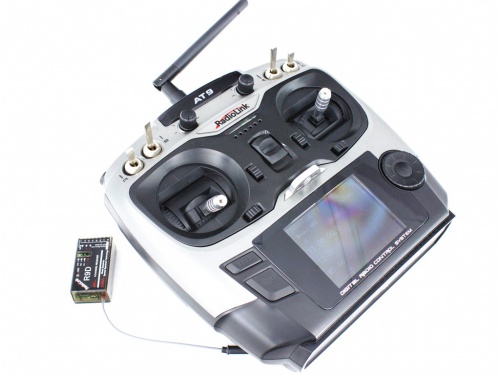
- 9 Внутренности RadioLink AT9
- 10 FAQ
- 10.1 Как называется разъём тренерского порта
- 10.2 Как включить сигнализацию о плохом сигнале
- 11 Обзоры
- 12 Отзывы
- 13 Инструкции
- 13.1 Видео
- 13.1.1 Настройка
- 13.1.2 Модернизация
- 13.1 Видео
- 14 Прошивки
- 14.1 Прошивка 1.2.6
- 15 Тюнинг
- 16 Где купить RadioLink AT9
- 17 Ссылки
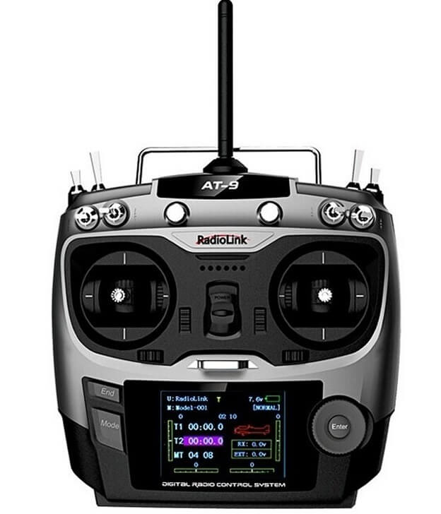
Описание[править]
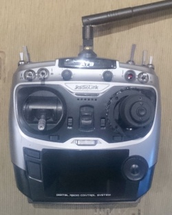
RadioLink AT9 — 10-канальная аппаратура радиоуправления, работающая по протоколу DSSS с поддержкой S.BUS и Fail Safe.
Видео-обзор RadioLink AT9 и сравнение с FlySky TH9x.
Таблица-сравнение с другими аппаратурами.
Где купить RadioLink AT9[править]
Найти все предложения по RadioLink AT9 на RCSearch.
Комплектация RadioLink AT9[править]
- Пульт управления RadioLink AT9
- Инструкция
- 9-ти канальный приёмник R9D (на выходе S.BUS доступно 10 каналов)
Особенности RadioLink AT9[править]
- Структура меню скопирована с Футабы.
- Наличие специального меню для мультикоптеров (кроме обычных настроек для планеров, самолётов и вертолётов).
- Поддержка телеметрии (RSSI, напряжение питания приёмника и силовой батареи, GPS, температура, высота, обороты мотора).
- Предупреждения звуком и вибрацией
- Порт micro USB для возможности обновления прошивок
- Цветной LCD дисплей с настраиваемой контрастностью
- Детализация 4096 точек на каждом канале
- Настраиваемый Fail Safe на каждом канале
- Меню настройки похоже на Futaba 10
- Три 3-позиционных переключателя, два слайдера и две крутилки, которые можно назначить на один из каналов 5..9
- Возможность отключить ВЧ-модуль для режима тренера или авиасимулятора
- Помехозащищенный протокол DSSS
- Цифровые триммеры
Характеристики RadioLink AT9[править]
- Частота: 2.4ГГц ISM band (2400..2485 МГц)
- Количество каналов: 10
- Количество запоминаемых моделей: 15
- Вес: 880 г
- Размер: 183x193x100 мм
- Напряжения питания: 8.6~15В
- Энергопотребление: <105мА (при выключенном ВЧ-модуле 70мА)
- Время отклика: 3 мс (в среднем у разных аппаратур — 20 мс)
- Дальность действия: 900м по земле, более 1500м по воздуху
- Экран: 2.8″ 16 цветов , разрешение 240х320
Достоинства[править]
- Хорошая дальность приёма (~ 1 км)
- Поддержка S.BUS на приёмнике
- Индикация уровеня сигнала
- Возможность подпружинить стик
- Компактная
Недостатки[править]
- Отсутствует защита от неправильного подключения батареи (защита от переполюсовки)
- Плохо читается экран в солнечный день, способы лечения:
- установка прошивки 1.2.6 OSD и выше.
- замена цвета экрана с черного на белый.
- наклейка матовой пленки на экран.
- Откройте пульт и проверьте сопротивление между антенной и оплёткой экранирования. У многих там близко к короткому замыканию: дистанция радиопередачи у такой аппаратуры будет небольшой. Много сообщений об этом браке производства.
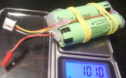
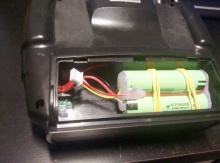
Батарея[править]
Штатное питание RadioLink AT9 — восемь батареек или аккумуляторов AA, установленных в съёмную кассету.
Размер батарейного отсека: 110х35х29 мм, можно использовать LiPo-аккумуляторы 2S или 3S подходящего размера.
Не очень хорошо закрывается крышка батарейного отсека, лечится очень просто: надо с силой закрыть, не боясь сломать.
Вариант самодельной батареи: 2 элемента Li-Ion по 3.4 В
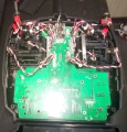
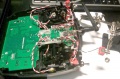
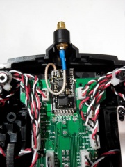
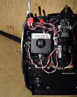
Внутренности RadioLink AT9[править]
FAQ[править]
Как называется разъём тренерского порта[править]
В RadioLink AT9 в качестве разъёма тренерского порта применяется стандартный разъём S-Video, он же Mini-DIN 4, он же MD4P, соответствующий штекер можно купить в радиомагазинах или на радио-рынках.
Как включить сигнализацию о плохом сигнале[править]
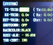
![]()
Некоторые приёмники (например, RadioLink R9DS и RadioLink R6DSM) передают на пульт данные телеметрии, в частности — RSSI, уровень сигнала управления. Пульт RadioLink AT9 может вибрировать при уровне RSSI, ниже заданного значения. Настройка этого значения располагается в меню SYSTEM / RSSI-ALM.
Обзоры[править]
- Видео: Распаковка, первое знакомство (рус.)
Отзывы[править]
- Очень смущает одна антенна на приемнике. Как её располагать на модели, чтобы над головой работала и на удалении хотя бы 1км? Было: самолёт прилетел на автовозврате, крутит над головой на 100м, а связи нет. Пришлось отбежать на сотню метров в сторону с пультом, там поймать кратковременную связь и с трудом посадить. Перевернул антенну усиком вниз. Получше, но не намного. Вобщем что то одно, или класть антенну лежа чтобы слетать вверх, или ставить вертикально чтобы в даль. Для FPV в этом смысле крайне неудобный приемник. Ну и сильно гасится видеопередатчиком 1,2 ггц, если без фильтров. [1]
- Функционал настроек и сам дисплей — супер, SBus на приёмнике, обратная связь с показаниями напряжения, но по связи очень разочаровался. На ютубе распиарили дальностью аж до 4 км, но пока как антенну не крутил, дальше 1200м, периодически славливая Fail Safe на всем пути, не улетел. [2]
Инструкции[править]
- Инструкция на русском AT9_manual_ru_(partially).doc (частично)
- Инструкция на английском: RadioLink_AT9.pdf Radiolink_AT9.doc
Видео[править]
Настройка[править]
- Как прошивать аппаратуру Radiolink AT9 (рус.)
- Как забиндить RadioLink AT9, настройка Fail Safe (рус.)
- Калибровка стиков RadioLink AT9 (рус.)
- Настройка RadioLink AT9 для FBL-вертолета. (рус.)
- Настройка RadioLink AT9 для летающего крыла. (рус.)
- Настройка RadioLink AT9 для полётного контроллера NAZA. (рус.)
- Настройка RadioLink AT9 для полётного контроллера Tarot ZYX-M (рус.)
- Датчик PRM-01: Как подключить Как откалибровать (рус.)
- Датчик PRM-02: Как подключить (рус.)
Модернизация[править]
- Переделываем левый стик под полетные контроллеры типа NAZA
- Готовим аппаратуру для установки бустера на 2,4 Ghz
- Варианты использования приемника R6D, PPM
Прошивки[править]
Видео — как прошивать аппаратуру Radiolink AT9
Утилиты для прошивки:
- Программа для установки прошивки
- Драйвера для прошивки: Windows XP/7 Windows 8/10
Файл прошивки 1.1.5
Файл прошивки 1.1.8
Прошивка 1.2.6[править]
Появилось OSD!
Видео-обзор и отличия от предыдущих
Файл прошивки 1.2.6
Тюнинг[править]
![]()
Разъём SMA (или RP-SMA) для установки нештатных антенн
- Установка антенного разъёма вместо родной сосиски, на который можно поставить различные нештатные антенны, а также подключить бустер.
- Подключение бустера (например, на 2 Вт) для увеличение дальности радиоуправления. Удобно подключать к разъёму, как описано выше. Для бустера понадобится питание, можно подпаяться на плате пульта, на площадки рядом со штекером подключения блока батарей, а сам кабель питания вывести через отсек батарей.
- Замена пальчиковых батареек/аккумуляторов на LiPo-аккумулятор, что особенно актуально при подключении и питании бустера, как описано выше. Проверенные модели LiPo-аккумуляторов для RadioLink AT9: aliexpress
- Установка трёхпозиционного джойстика «single stick» для более интуитивного, натурального управления квадрокоптерами: см. фото ниже. Подробнее задавайте вопросы на [email protected]
Где купить трёхпозиционный джойстик «single stick»
- Установка дополнительного радиомодуля (см. фотогалерею)
Где купить RadioLink AT9[править]
Найти все предложения по RadioLink AT9 на RCSearch.
Ссылки[править]
- Описание на сайте производителя.
- Инструкция на русском (частично) AT9_manual_ru_(partially).doc
- Инструкция на английском Radiolink_AT9.doc RadioLink_AT9.pdf
- Видео-обзор RadioLink AT9 и сравнение с FlySky TH9x.
- Таблица-сравнение с другими аппаратурами.
- Доработка RadioLink AT9: дополнительный радиомодуль и замена стика
- Обсуждение на форуме flycamstudio.ru
-
16.01.2020
1111
Сегодня познакомимся с продукцией китайской компании Radiolink, которая специализируется на производстве аппаратур для радиоуправляемых моделей. Речь сегодня пойдет о великолепной радиоаппаратуре среднего уровня radiolink AT9.
Комплектация
В отличие скажем от народной аппаратуры Turnigy 9x, где по факту пользователю доступно только 8 каналов, в Радиолинк AT9 это честные 9 каналов прямо из коробки. Аппаратура работает на частоте 2.7 Ггц.
В комплекте поставляется инстурукция в которой подробно описано, как пользоваться аппаратурой, все доступно и понятно. Если вы новичок рекомендуем с инструкцией ознакомиться – будете понимать, что такое двойные расходы, микширование или экспонента.
9 канальный приемник radiolink AT9, достаточно маленький и легкий. Приемник и передатчик поддерживают телеметрию, так что есть возможность подключения дополнительного оборудования для контроля заряда аккумулятора, качества сигнала и т.д. Подключение 8 каналов осуществляются через вертикальные разъёмы, 9 канал – горизонтальный разъем по совместительству S-BUS. Для переключаться между 9-м каналом и s-bas портом используется кнопка на боку приемника.
Также в комплекте поставляется рычажок и пружинка, чтобы подпружинить ручку газа и собственно сам передатчик.
Передатчик
radiolink AT9 сделан из качественного пластика, зазоры между элементами минимальные, все очень достойно. На передатчике расположены:
- 3 –ри 3-х позиционных переключателя;
- 4-ре 2-х позиционный переключателя
- 2-ве крутилки;
- 2-ва слайдера сзади
- тренерский порт сзади пульта
- кнопки навигации по меню (справа колесико, которое можно нажимать, слева кнопка меню и выход из меню)
Внизу аппаратуры расположен micro USB порт для прошивки. Запитывается пульт либо от батарейного блока на 8 патареек AA, либо от аккумулятора напряжением от 7.4 до 18 вольт.
Размеры аккумуляторного отсека – 116х32х35 мм.
Radiolink AT9 оборудован цветным дисплеем диагонялью 2.8 дюйма с разрешением 320х240 пикселей.
Меню передатчика
В меню доступны два вида BASIC MENU и ADVANCED MENU.
В BASIC MENU доступны следующие подменю:
- Параметры (PAREMETER): позволяет менять язык (английский/китайский), раскладка стиков (MODE1, MODE 2, MODE 3, MODE 4), включение/выключение режима авиасимулятора а также параметры напряжения приемника и передатчика при которых будет срабатывать сигнализация.
- MODEL SEL: позволяет выбрать какую модель мы будем использовать из настроенных нами;
- MODEL TYPE: позволяет задать модель. Доступны следующие типы: самолеты, планеры нескольких видов, вертолеты или мультироторные модели.
- END POINT: конечные точки для всех каналов.
- SUB-TRIM: саб-триммеры для каналов
- REVERSE: реверсы
- DR/EXP: двойные расходы и экспоненты для 4-х каналов
- Функции THROTTLE CUT и IDLE DOWN (холостой ход) настройки для ДВС.
- TRIM: настройки шагов триммеров для каждого канала
- F/S: очень полезная функция позволяющая задать значение каждого канала при потере сигнала.
- AUX-CH: выбор переключателей для дополнительных каналов
- TIMER: можем установить три таймера и кнопки, при помощи которых они могут активироваться.
- TRAINER: можем задавать функции которые мы контролируем как тренер или ученик
- LOGIC SW: функция активирования с одного переключателя сразу нескольких функций
- SERVO: мониторинг всех каналов, реакции каналов
- RECEIVE: пункт меню приемника. Можем видеть напряжение, обороты, силу приема передачи сигнала RSSI.
ADVANCED MENU (для самолета)
- PROG MIX: Микширование каналов, 4 линейных программируемых микса и 4 кривые по 5 точкам
- FLAPERON: можем использовать элероны в качестве закрылок
- FLAP TRIM: триммирование флаперонов
- AILE – DIFF: настройка элеронов подключенных к отдельным каналам
- AIR-BRAKE: воздушныйтормоз
- ELEV-FLAP: микширование элеронов и руля высоты, если поднимаем руль высоты вверх, наши элероны опустятся вниз, это позволяет делать быстрые маневры
- AILVATOR: настройка руля высоты которой, например, имеет два сервопривода подключённых к разным каналам
- SNAP-ROLL: вращение модели которое можем активировал переключателем
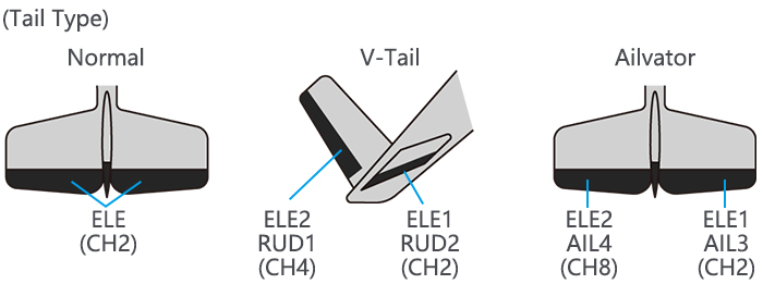
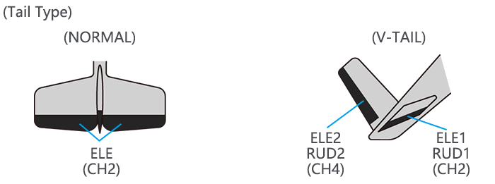
- V-TAIL: настройка для самолетов и планеров с особым хвостовым оперением
- ELEVON: настройка управляющих поверхностей на летающих крыльях
- GYRO-SENSE: переключение чувствительности нашего гироскопа
- THR-CURVE: кривые газа, поддерживается 5 точек не считая нулевого и максимального положения
- THR-DELAY: настройка задержки газа (для ДВС мотора)
- THR-NEEDLE: настройка подачи топлива (для ДВС мотора)
ADVANCED MENU (для мультикоптера)
- ATTITUDE: с помощью 2-х 3-х позиционных переключателей можно настроить 6 полетных режимов (полезная штука для владельцев контроллеров ArduPilot Mega)
- THR-CURVE: кривые газа
- PROG MIX: меню микширования
В случае, если батарейка в передатчике села, он оповещает нас звуковым сигналом, предупреждением на экране и вибрацией вибромоторчика.
Производитель обещает дальность приема сигнала 1,5 км.
Выводы
Выводы прекрасная аппаратура, сделанная из качественных материалов, и обладающая хорошей функциональностью. Порадовала возможность установки таймера, знаешь сколько времени летать и когда нужно сажать модель. Хорошие настройки для коптеров которые позволяют задать несколько полетных режимов.
Стоимость radiolink AT9 обойдется около 90 USD, radiolink AT9S составит около 120 USD
Установка пружинки для возврата газа в центр.
Подключение radiolink at9 к полетному контроллеру DJI NAZA.
Introduction of AT9S Pro
Note that in the text of this manual, beginning at this point, any time we are using a feature’s specialized name or abbreviation as seen on the screen of the AT9S Pro, that name, feature, or abbreviation will be exactly as seen on the radio’s screen, including capitalization and shown in a DIFFERENT TYPE STYLE for clarity, Any time we mention a specific control on the radio itself, such as moving SWITCH A, KNOB VR(B), or the THROTTLE STICK, those words will be displayed as they are here.
AT9S Pro System
Transmitter Functions
Aero basic
•V tail •Twin Aileron Servos
•Elev-flap mix •Twin Elevator Servos
•air brake •Snap roll
•Gyro mixing
Glider (3 wing model: 1A+1F/2A+2F/1A+2F)
•V tail •Twin Ailerons
•Elevon •Butterfly
•Offset
•5 flight conditions (normal, start, speed, distance, landing)
•IDLE- DOWN (ACRO), THR-CUT (ACRO HELI) (engine shut off), and MOTOR CUT (GLID) setups to allow precise engine/motor control for taxi and landings.
•15 model type memory
•New stick design with improved feel, adjustable length and tension.
•Triple rates available by setting dual rates to 3-position switches.
•Eight SWITCHES, 3 DIALS and 2 SLIDERS; completely assignable in most applications.
•Trainer system includes the “functional” (FUNC) setting, which allows the student to use the AT9’s mixing, helicopter, and other programming functions even with a 4-channel buddy box. (Optional trainer cord required.)
•AT9S Pro transmitter features airplane friendly switch layout, with the trainer switch at the left hand (Mode 2), and a notched throttle to minimize throttle changes with rudder input. Defaults to ACRO model type.
•AT9S Pro transmitter features helicopter-friendly switch layout, with idle-up and throttle hold switches at the left hand, and a smooth, ratchet-less (unsprung) throttle for perfect hovering. Defaults to HELI (H-1 swash plate type) model type
Helicopter (8 swashplate types, including CCPM)
• 3 Idle Ups • Throttle and Pitch Curves per Condition
• Revo. Mixing • Gyro Mixing including Separate Settings per Condition
• Delay • Governor Mixing
MULTIROTOR:
• ATTITUDE (Normal, attitude, GPS, hover, F/S, Aux)
• Throttle curve
• Mix programmable
Transmitter
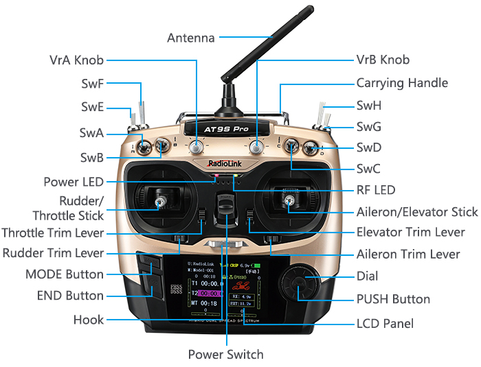

1.Earth Pole
2.Null
3.Voltage Input: 7.4-18V
4.Output: PPM/SBUS/CRSF
5.Input: RSSI
SWITCH ASSIGNMENT TABLE
• The factory default functions activated by the switches and knobs for a AT9S Pro transmitter are shown below.
• Most AT9S Pro functions may be reassigned to non-default positions quickly and easily. Always check that you have the desired switch assignment for each function during set up.
|
Switch/Knob A or H |
Airplane (ACRO) |
Sailplane/Glider (GLID) |
Helicopter (HELI) |
MULTIROTOR |
|
SWITCH A |
elevator dual rate ch10 |
elevator dual rate ch10 |
elevator dual rate ch10 |
elevator dual rate ch10 |
|
SWITCH B |
rudder dual rate ch9 |
rudder dual rate ch9 |
rudder dual rate ch9 |
rudder dual rate ch9 |
|
SWITCH C |
up = ELE-FLP on down = AIRBRAKE on |
up = ELE-FLP on center = Distance cond. down = Landing cond. |
governor |
attitude |
|
SWITCH D |
aileron dual rate |
aileron dual rate |
aileron dual rate |
aileron dual rate |
|
SWITCH E or G* |
Landing gear/ch5 |
—— |
Throttle hold/ch5 |
—— |
|
SWITCH F or H* |
Snap roll /trainer |
Trainer |
Trainer/throttle cut |
trainer |
|
SWITCH G or E* |
—— |
up = Speed cond. |
idle-up 1 and 2 |
—— |
|
SWITCH H or F* |
—— |
down = Start cond. |
idle-up 3 /gyro |
—— |
|
KNOB A |
Flap/ch6 |
Flap/ch6 |
HOVERING PITCH |
ch 6 |
|
KNOB B |
ch 8 |
ch 8 |
ch 8 |
ch 8 |
|
KNOB C |
Spoiler/ch7 (disabled if AIL-DIFF on) |
ch 7 (disabled if AIL-DIF on) |
HOVERING THROTTLE ch7 |
ch 7 |
|
SLIDER D |
—— |
ch 5 |
—— |
—— |
Compatible Receivers
AT9S Pro is a 12 channels transmitter, support 2.4G DSSS and FHSS dual hybrid spread spectrum, 16 channels pseudo random frequency hopping.
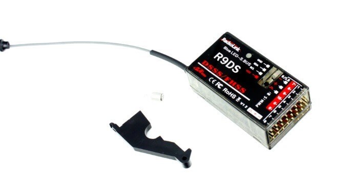
AT9S Pro sells with receiver R9DS.
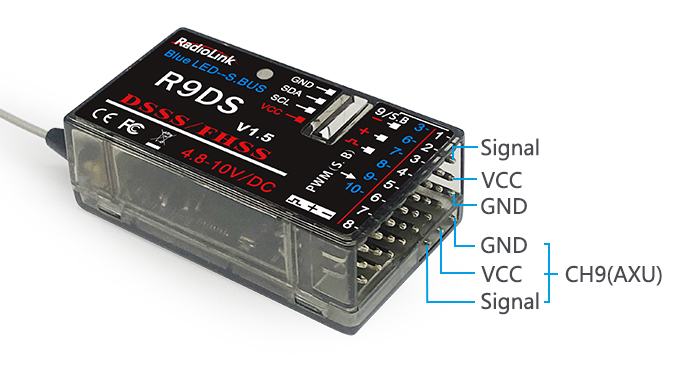
R9DS is a 9 channels receiver when working with PWM signal(red LED), it will a 10 channels receiver when working with S-BUS signal(purple/blue LED).
Besides R9DS, AT9S Pro is also compatible with Radiolink R6DS, R10DS, R12DS and super mini 10 channels receiver R6DSM and 12 channels mini dual antenna receiver R12DSM.
R6DS, is a 6 channels receiver when working with PWM signal while it is a 10 channels receiver when working with SBUS or PPM signal.
R12DS, is a 11 channels receiver when working with PWM signal while it is a 12 channels receiver when working with SBUS signal.
Note AT9S Pro is default 10 channels, you can upgrade it to 12 channels with USB cable. You have to setup AT9S Pro to 12 channels first if you use 12 channels receivers R12DS or R12DSM while you have to setup AT9S Pro back to 10 channels when you use 10 channels receiver R6DS, R6DSM and R10DS.
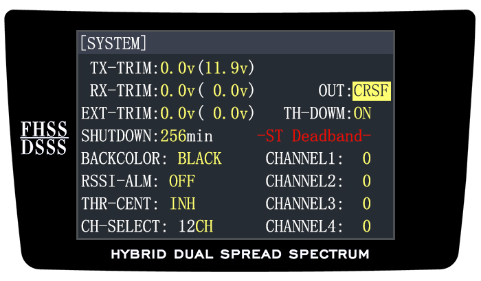
To setup to 12 channels: power on your AT9S Pro—Press Mode button one second into BASIC MENU—into SYSTEM menu—change CH-SELECT from 10CH to 12CH.
Since Radiolink radio control systems are not open source, that Radiolink transmitters just compatible with Radiolink receivers and vice versa.
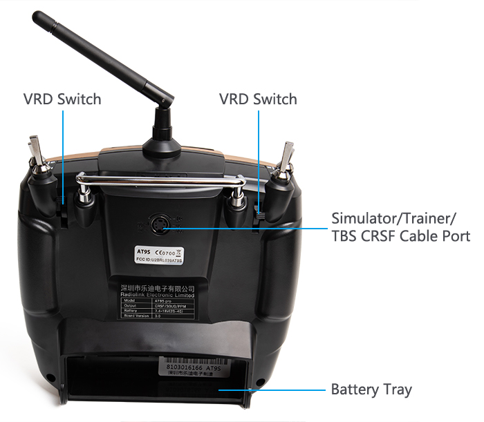
Connect to TBS Crossfire TX
- Power on the transmitter- Long press the Mode key to enter the BASIC MENU->Rotate the Scroll Dial to highlight the SYSTEM option and depress the Enter key->Select the OUT and change the output as CRSF
Note There are totally three signal output SBUS/PPM/CRSF
- Connect the TBS Crossfire transmitter to the AT9S Pro with the cable(packed inside the box)
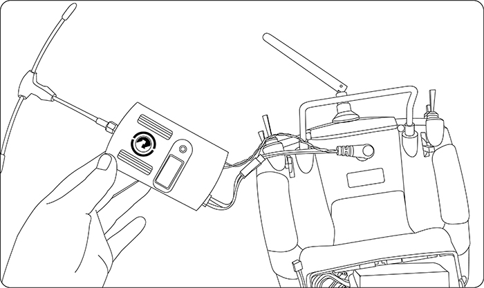
The detailed steps please refer to the video tutorial https://youtu.be/g_mfHdeEQCo
Note The compatibility function with TBS Crossfire TX is only available in AT9S Pro, which CANNOT be upgraded from AT9S Pro directly.
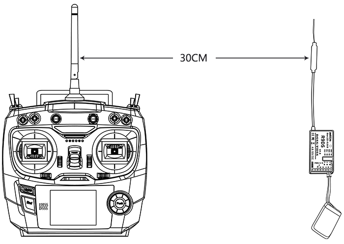
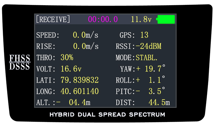
RSSI testing
Power on transmitter and receiver, keep transmitter apart from receiver about 30 centimeters and both antennas straight.
Enter the parameter setup menu by press MODE one second, you can check the RSSI in RECEIVE.
The RSSI is 0 to 30dBm is normal when the transmitter is apart about 30 centimeters from the receiver, the signal is more better the RSSI data is more close to 0.
Radio Installation
Mount the Servos, Receiver and Battery
• Make certain the alignment tab on the battery, switch and servo connectors is orient correctly and ‘key’ into the corresponding notch in the receiver or connectors before plugging them in .When unplugging connectors, never pull on the wires. Always pull on the plastic connector instead.
• Receiver’s Antenna: In generally receiver’s antenna is longer than remote control, don’t break or retract it, otherwise shorten the control distance. The antenna must be kept away from conductive materials, such as metal. Please make distance test before flying.
• If your aileron servos are too far away to plug into the receiver, use an aileron extension cord to extend the length. Avoid plugging multiple extensions together to obtain your desired length. If the distance is greater than 50cm or high current draw servos are being used, use heavy servo extensions.
• Receiver Vibration and Waterproofing: the receiver contains precision electronic part. Be sure to avoid vibration, shock, and temperature extremes. For protection, wrap the receiver in foam rubber or other vibration-absorbing materials. It is also a good idea to waterproof the receiver by placing it in a plastic bag and securing the open end of the bag with a rubber band before wrapping it with foam rubber. If you accidentally get moisture or fuel inside the receiver, you may experience intermittent operation or a crash. If in doubt, please contact Radiolink aftercares or distributors for service.
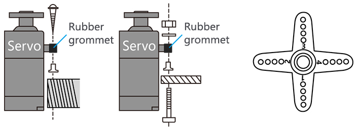
• Always mount the servos with the supplied rubber grommets. Don’t over tighten the screws. No part of the servo casing should contact the mounting rails, servo tray or any part of structure. Otherwise vibration will be transmitted to the servo causing damage of servo. Note the small numbers (1, 2, 3, and 4) molded into each arm on the servo arms. The number indicate how many degrees each arm is ‘off’ from 90 degrees to correct for minute manufacturing deviations from servo to servo.
• To center the servos, connect them to receiver and turn on the transmitter and receiver. Center the trims on the transmitter, then find the arm that will be perpendicular to the pushrod when placed on the servo.
•After the servos are installed, operate each servo over its full travel and check that the pushrods and servo arms don’t bind or contact each other. Also make sure the controls do not require excess force to operate. If there is an objectionable buzzing sound coming from a servo, there is probably too much resistance in the control. Find and correct the problem. Even is there is no servo damage, excess battery drain will result.
• Use the mounting plate from the receiver on/off switch as a template for the cutout and screw holes, mount the switch on the side of the fuselage opposite the engine exhaust, and where it won’t be inadvertently turned on or off during handling or storage. Be certain the switch moves without restriction and ‘snaps’ from ON to OFF, and that the cutout allows full motion of the switch in both directions.
• When install the switch harness to the helicopter please use the switch cover. Generally sandwich the frame between the switch and switch cover and securely tighten the screws, Different models might require different installations. If so, please follow the model’s instruction manual.
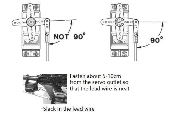
• To prevent the servo lead wires from being broken by vibration during flight, provide a slight amount of slack or extra so that the wire sticks out slightly and fasten it at suitable points. In addition, periodically check the wire during daily maintenance.
Receiver and Servo Connections
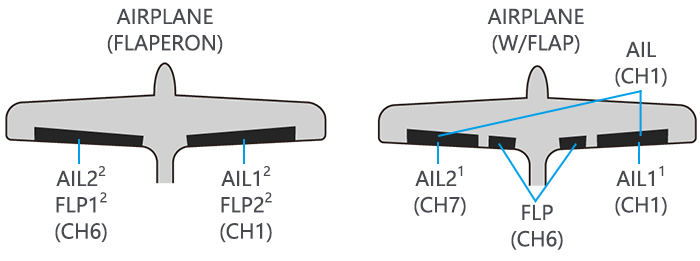
(1) Acrobasic servo connection
|
Receiver output and channel |
ACROBASIC |
|
1 |
ailerons/aileron-1¹/combined flap-2&aileron-1¹ |
|
2 |
elevator |
|
3 |
throttle |
|
4 |
rudder |
|
5 |
spare/landing gear/aileron-2¹ ³/combined flap-1 and aileron-2² ³ |
|
6 |
spare/flaps/combined flap-1 and aileron-2² |
|
7 |
spare/aileron-2¹ |
|
8 |
spare/elevator-24/mixture control |
|
9 |
spare |
|
10 |
spare |
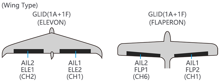
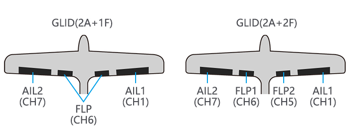
(2)Glider/Sailplane servo connection
|
RX output & CH |
Glider |
|||
|
GLID(1A+1 F) |
GLID (2A+1F) |
GLID (2A+2F) |
||
|
ELEVON |
FLAPERON |
AILE-DIFF |
AILE-DIFF |
|
|
1 |
Combined elev-2&aileron1 elev-1&aileron-2 |
Combined flap-2 &aileron-1 |
aileron-1 |
Aileron-1 |
|
2 |
Combined elev-1&aileron-2 |
Elevator/combined rudder-2&elev-1¹ |
Elevator/combined rudder-2&elev-1¹ |
Elevator/combined rudder-2&elev-1¹ |
|
3 |
spare/motor |
spare/motor |
spare/motor |
spare/motor/splr-2¹ |
|
4 |
Rudder |
Rudder/combined rudder-2&elev-2² |
Rudder/combined rudder-2&elev-2² |
rudder/combined rudder-1&elev-2² |
|
5 |
spare/splr-2¹ |
spare/spoiler-2¹ |
spare/spoiler-2¹ |
flap-2 |
|
6 |
Flaps |
Combined flap-1&aileron-2 |
flaps |
flap-1 |
|
7 |
Spare |
spare |
ailron-2 |
Aileron-2 |
|
8 |
spare/splr/splr-1¹ |
spare/splrs/splr-1¹ |
spare/splrs/splr-1¹ |
spare/splrs/splr-1¹ |
|
9 |
Spare |
spare |
spare |
spare |
|
10 |
Spare |
spare |
spare |
Spare |
(3)Helicopter servo connection
|
Receiver output and channel |
Helicopter |
|
1 |
aileron/cyclic roll |
|
2 |
Elevator/cyclic pitch |
|
3 |
Throttle |
|
4 |
Rudder |
|
5 |
Spare/gyro |
|
6 |
Pitch(collective pitch) |
|
7 |
Spare/governor |
|
8 |
spare/mixture control |
|
9 |
Spare |
|
10 |
spare |
The above listed receiver and channels is referred to the channel 1~9 of the receiver R9DS, connect the receiver with the related servo, you can control the servos by the correspondent switch.
To be clear, the servo connected with the receiver channel 1 is controlled by the radio aileron lever; servo connected with channel 2 is controlled by elevator lever; servo connected with channel 3 is controlled by throttle stick; servo connected with channel 4 is controlled by the rudder lever. Channel 5~9 can be self-set with the related switches by the menu AUX-CH, and the sub menu. For channel 9, the LED indicator on the receiver flashes blue for S-BUS signal and red for PWM.
Installment of Antenna
Installment of antenna
- Receiver Antenna Installment
- Keep antennas as straight as possible, or the effective control range will reduce.
- Big models may contain metal parts that influence signal emission. In this case, antennas should be positioned at both sides of the model to ensure the best signal status in all circumstances.
- Antennas should be kept away from metal conductor and carbon fiber at least half inch away and no over bending.
- Keep antennas away from motor, ESC or other possible interference sources.
- Press and hold the ID SET for more than one second and receivers will start to work with the RED LED on.
Note Receiver contains some electronic components of high-precision. Be careful to avoid strong vibration and high temperature.
When all the above steps are complete, please turn off the transmitter and repower on to test if the receiver is correctly connected with it.
- Transmitter Antenna Installment
- The transmitter antenna is adjustable so please make sure that the antenna never points directly at the model when flying as this may possibly decrease the receiver signal.
- Keep the antenna perpendicular to the transmitter to optimize the receiver performance. It also depends on how you hold the transmitter. But in most cases, adjusting the antenna with perpendicular position to the transmitter surface will achieve the best result. Please adjust the transmitter antenna according to the way you hold the transmitter.
- Never grip the antenna when flying as this degrades= effective control range..
Radio Basic Setting
Basic Setting of Transmitter
- Display language: can be selected the display language of the function name, etc. in each function menu. The screen reads «LANGUAGE». Change this to the desired language.
- Stick Mode: The screen reads «STK-MODE». Change this to the correct mode. Note that this will NOT change the throttle and elevator ratchets, etc. Those are mechanical changes that must be done by a service center.
- RF Mode: the LED indicator will become solid green when RF Mode is active.
- Adjusting Display Contrast: To adjust the display contrast, from the home menu press and hold the END BUTTON. Turn the DIAL while still holding the END BUTTON: clockwise to brighten and counterclockwise to darken the display.
- User name setting: user name can be set by DIAL and PUSH with letters and numbers.
- Alarming voltage:
Transmitter: preset 8.6V, can be self-set
Receiver: preset 4.0V, can be self-set
Ext: preset 10.1V, can be self-set
Model Type
Under basic menu, use DIAL to select MODEL TYPE and enter by pressing PUSH. There are 6 different type included in the system, HELICOPTER, AEROBASIC, GLID(1A+1F), GLID(2A+1F), GLID(2A+2F), and MULTIROTOR, after model type is selected, press and hold PUSH for 1 second, when the word “are you sure to change” displayed, model type is changed.
Binding
Each transmitter has an individually assigned, unique ID code. Receiver should bind to transmitter before starting operation. Once binding is complete, the ID code will be stored in the receiver and no further binding is necessary unless the receiver is used with another transmitter. When you purchase a new R9DS, this procedure is necessary; otherwise the receiver will not work.
1. Put the transmitter and the receiver close to each other about 50 centimeters.
2. Power on AT9S Pro and receiver R9DS. The RED LED will be on.
3. Turn on AT9S Pro and it will automatically bind with the closest receiver.
4. There is a black binding button (ID SET) on the side of receiver. Press the button for more than 1 second and release, the RED (by default, could be Purple for SBUS&PWM signal output) LED will flash, meaning binding process is ongoing.
5. When the LED stops flashing and is always on , binding is complete.
6. Make sure servos connected with the receiver can be operated by the transmitter.
Working Modes of R9DS
There are two signal working modes, PWM and SBUS&PWM signal output. Short press ID SET twice within 1s, the working mode will change.The RED led indicates the PWM output and BLUE/PURPLE led indicates SBUS signal.
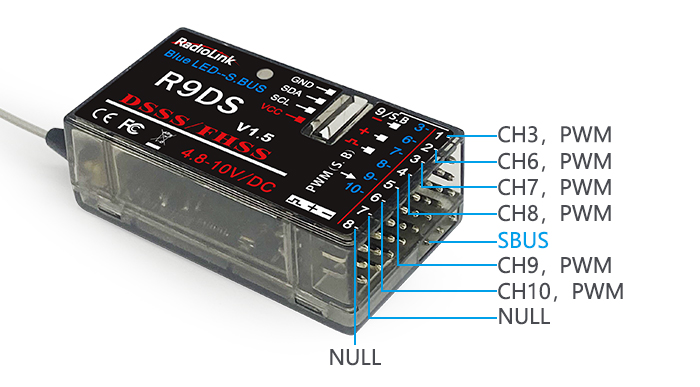
(1) PWM signal output working mode:RED led indicates PWM signal output, 9 channels totally

(2) SBUS&PWM dual signal output working mode: blue/purple LED indicates SBUS&PWM signal output at the same time with 10 channels totally. CH9 outputs SBUS signal while the original CH1 outputs CH3 PWM signal and original CH2 to CH6 output CH6 to CH10 PWM signal at the same time.
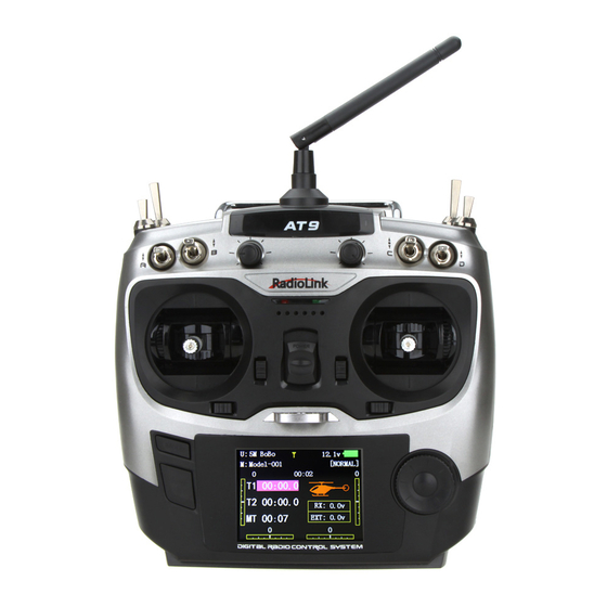
Transmitter Displays & Buttons
When you first turn on your transmitter, a confirmation double beep sounds, and the screen shown below appears. Before flying, or even starting the engine, be sure that the model type and name appearing on the display matches the model that you are about to fly! If you are in the wrong model memory, servos may be reversed, and travels and trims will be wrong, leading to an immediate crash.
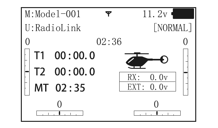
Total timer: Shows the cumulated ON times. (Hours: minutes)
T1/T2:T1/T2 timer display.(minutes: seconds)
MT:Model timer display Shows the cumulated ON time for each model.(hours: minutes)
Button instruction
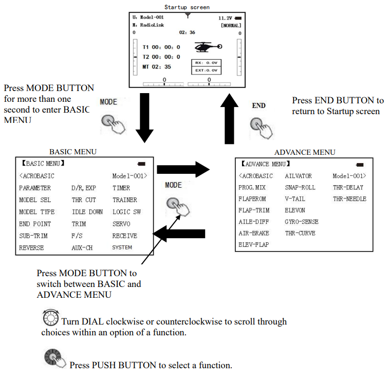
MODE BUTTON
Press and hold MODE BUTTON for one second to open programming menus. Press MODE BUTTON to switch between BASIC and ADVANCE. Press MODE BUTTON to scroll between conditions in certain functions.
END BUTTON:
Press END BUTTON to return to previous screen. Closes functions back to menus, closes menus to start-up screen.
PUSH BUTTON:
Press PUSH BUTTON to select a function.
Turn DIAL:
Turn DIAL clockwise or counterclockwise to scroll through choices within an option of a function
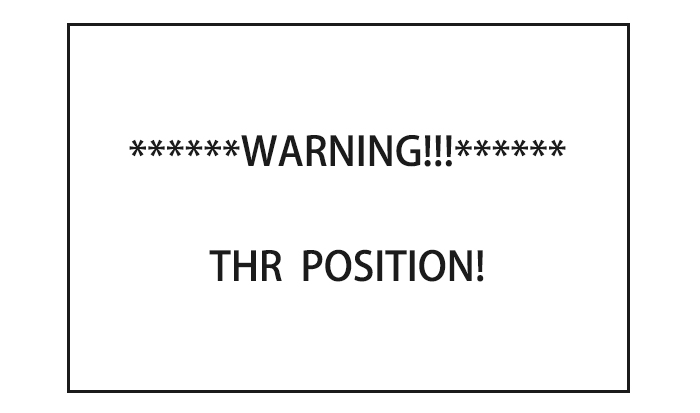
Warning and error display
When the transmitter is powered on, warning or error may happen by the following probability
- Battery low voltage alarming
Lithium battery 2S-4S can fit for the transmitter, warning voltage can be self-set according to different battery.
Setting step: power on the transmitter, press and hold MODE one second to enter basic menu, and press PUSH to enter PARAMETER. Choose TX ALARM by DIAL and PUSH to change relative data. Suggested min voltage is not less than 7.4V.
When the transmitter voltage is less than the setting voltage, it will beep till the transmitter is powered off. Most important thing is to land your model plane when the transmitter alarms.
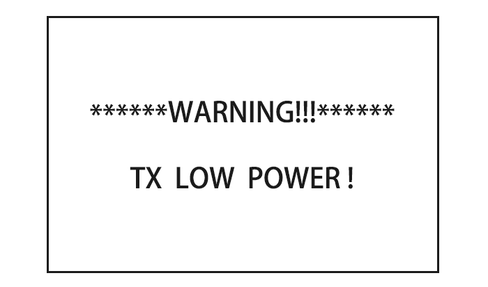
2. Mixing alarm
When the transmitter alarms mixing, it means at least one mixed switch is active. And when it is inactive, warning will stop then. When the transmitter is powered on, in different model type, mixing switch is shown as below:
ACRO: throttle cut, idle down, snap roll, air brake
GLID: butterfly, condition
HELI: throttle cut, throttle lock, speed up
If the warning continues even the related switch is set OFF, probably it is because some programs mixed by one switch and status OFF reversed. Now you need to set mixing alarm again by DIAL.
Basic Function of Airplane
Pay attention that the (BASIC) menu is suitable for all type models (airplane, helicopter, glider, MULTIROTOR, cars and boats). The motor cut will be introduced in Glider (Basic) Menu, except Idle down &Throttle cut. Helicopter Basic Menu include some extra function (swashplate tilting, throttle and pitch curves and the tail rotor anti torque mixing under normal flight model) will be discussed in Helicopter section.
Acro Basic Menu
Basic 4-channel Airplane
This guide is intended to help you acquainted with the radio, to give you some ideas and direction on how to do. We give you a big picture overview of what we accomplish; a ‘by name’ description of what we’re doing to help you with the radio; then a step-by-step instruction to leave out the mystery when setting up your model.
For additional details on each function, see that function’s section in this manual.
|
Example |
Steps |
Input for Example |
|
|
Prepare your airplane |
Install all servos, switched, receivers, etc. per your model’s instructions. Turn on transmitter then receiver; adjust all linkages so surfaces are nearly centered. Mechanically adjust all linkages as close as possible to proper control throws. Check servo direction. Make notes now of what you will need to change during programming. |
||
|
Name the model (Note that you do not need to do anything to ‘save’ or store this data). |
Open the Basic menu, then open the PARAMETER |
Turn on the transmitter. |
|
|
Go to Model Name |
|
||
|
Input airplane’s name |
|
||
|
Need to adjust END-POINT to meet with the related servo. |
In the BASIC menu find the END POINT |
|
|
|
Adjust end point (EX: THRO servo)Close the function |
|
||


With digital trims you don’t shut the engine off with THROTTLE TRIM. Let’s set up IDLE-DOWN and ‘throttle cut’
|
Goals |
Steps |
Input for Example |
|
Idle down setting: Idle down is to lower the engine speed for landing, snap rolling acrobatic display, and launching etc. It is preset OFF and mainly used to start engine and glide, then to avoid flameout. |
From the BASIC menu choose IDLE DOWN. |
|
|
Activate and adjust IDLE DOWN |
|
|
|
Optional: change switch C command |
|
|
|
Close the function |
|
|
|
THR CUT shuts the engine off completely with the flip of a switch.(Note: Do Not assign IDLE DOWN and THR CUT to both position of a 2 position switch |
From BASIC menu, choose THR CUT |
|
|
Activate, assign SWITCH and adjust. |
|
|
|
Set up dual/triple rates and exponential (D/P,EXP) (Note that in the middle of the left side of the screen is the name of the channel and the switch position you are adjusting. D/R may be set per channel by choosing the desired switch and mix rate. |
From BASIC menu, choose the D/R,EXP |
|
|
Choose the desired control, and set the first (EX: high) rate throws and exponential. |
|
|
|
Set the second(low)rate throws and exponential. |
SwA
Repeat steps above to set low rate. |


Airplane Basic Function
Model Select
Model submenu: includes three function that manage model memory: MODEL SELECT,MODELCOPY and MODEL NAME. Since these functions are related, and all basic features are used with most models, they are together in the Model submenu.
MODEL SELECT
Totally there are 15 models stored in the system, followed by model name and plane type to use on tap, thus you don’t need to set every time for different plane. MODEL NAME, MODEL TYPE and transmitter voltage. Make sure that MODEL TYPE is accomplished with your plane type before flight. Or it will cause error in servo and rudder.
COPY
Save the present data as another model type, it will be displayed by shadow area to differ from. When this copy start, the object data will be fully covered including name, type and module type, and cannot recover.
Caution: when you save the present model type as another, all related data will be copied including the original model name. Accordingly, if you want to change the model type, the whole data need to reset, also for model name. The first thing to copy is to change the model type or delete the original name and rename a new model to avoid confusion.
Model Name
This is used to set the present model name. Name all model to identify each other, and fast select the model type and reduce possible crash by wrong model type using.
Format to name a model:
•the name can be more than 9 characters
•every character can be letter, number, blank or special characters
•factory setting name MODEL-XXXX will be shown as (example model 1 display MODEL-0001)
|
Goals |
Steps |
Inputs |
|
Name model3“Cap-232_”(where underline represents a blank space |
Open Model |
|
|
Confirm correct model (Ex:3) |
If select doesn’t show ‘3’,perform Model select |
|
|
Go to Name to change the first character(Ex: M to C) |
|
|
|
Change the next character |
|
|
|
Repeat the prior steps until finish naming model. |
|
|
|
Close |
|
Sub-menu select: All parameters need one time setting. After the model type selected, you need to set the related data for it.
•what is the model type
•whether the throttle channel 3 is right for the selected model type? Or you need to make sure channel 3 is of full range adjustable (glider only). Also to different model, you can set by throttle reverse correspondingly.
Initialize the original data first, and set new data for the selected model type
Model reset: model reset is available in factory only. If you want to delete a new set model type, you need to delete one by one.
|
Goals |
Steps |
Inputs |
|
Reset model memory 1 |
Confirm you’re currently using the proper model memory(Ex:1) |
On home screen, check model name and No. on top left, if not correct use Model Select. |
|
Open PARAMETER submenu |
|
|
|
Reset the memory |
Push, |
|
|
Confirm the change |
Are you sure? Press PUSH |
|
|
Close |
|
Model type select
•ACRO basic:
Drive ACRO basic type (multi airfoil. Detail in Twin Aileron Servos, Twin Elevator Servos, ELEV-FLAP mix and V-tail)
•glider:
Different tail type (detail in glider type)
•helicopter:
8 swash plate types (detail in helicopter type)
Caution: decide a model type for the model plane. To most fixed wing plane, aero basic is better, because it has some function glider doesn’t have. While sometimes, glider (2A+1F) is better.
•functions specially for aero basic:
•snap roll
•ELEV-flap mix (twin Elevator Servos support)
•oil power plane: idle down、throttle shut、throttle needle mix etc.
•functions aero basic doesn’t have:
5 individual flight conditions (normal, start, speed, distance, landing)
If the model type selected for glider or helicopter, please go to the related chapter for setting. After model type changed, all parameters need to reset, including name.
Model Type(Airplane)
Data reset
All set data can be reset to factory setting. This function will not delete all model type set in the radio.
Setup step:
Enter the basic menu for MODEL TYPE, use dial to choose a proper type and press PUSH for one second, when the screen displays “are you sure”, press PUSH and the radio will beep, and it is set to factory data.
- Caution: don’t power the radio off before setting is finished, or the setting is invalid.
Model Select
|
Goals |
Steps |
Inputs |
|
Select proper Model Type for your mode l(Ex: ACRO) |
Open BASIC menu, then PARAMETER submenu |
Turn on the transmitter. MODE for 1s.(If ADVANCE, Mode again. |
|
Go to MODEL TYPE. |
|
|
|
Select proper type Ex: ACRO Confirm the change. Close. |
|
Second aileron  AILE-2) (ACROGLID1A+1FGLID2A+1F only): change the default choice for dual aileron servos from channels 6(FLAPERON) to channels 5 and 6, or channel 3 and 6, or channel 7(AIL-DIF) to channels 5 and 7. This allows you to utilize these 2 great functions while utilizing 5-channel receiver.
Caution: Changing AILE-2 only tells the system which servos to utilize if FLAPERON or AIL-DIF is activated. You still must activate that function and complete its setup for details on twin aileron servos, including using AILE-2.
(Only for glider 1A+1F) if the channel 3 is set as the second aileron, the receiver F/S will become invalid.
Adjustable travel limit (ATL)
Make the channel 3 TRIM LEVER (THROTTLE TRIM) effective only at low throttle, and disabling the trim at high throttle. This prevents pushrod jamming due to idling trim changes. This function defaults to ON. If you are not using channel 3 for throttle, you may want trim operation the same as on all other channels. To do so, set ATL to OFF. If you need the ATL to be effective at the top of the stick instead of the bottom, reverse the THR-REV setting. Note that this affects all models in the radio, not just the model you are currently editing.
|
Goals |
Steps |
Inputs |
|
Change ATL from ON to OFF for battling robots, tanks, airbrakes and other channel 3 uses. |
Open Basic menu, then to Mode Type. |
Mode for 1s (If ADVANCE, Mode again). |
|
Go to ATL and change. (Ex: to OFF) |
|
|
|
Close |
|
Home screen display
As shown below, home screen will display plane type and throttle pitch:
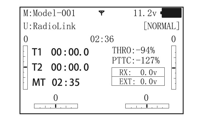
ILLUST: displays the illustration of helicopter in the home screen. (Default)
THR/PIT: displays the current throttle and pitch position in the home screen.
Step to change plane type image to THR/PIT: under model type helicopter, enter basic menu, choose MODEL TYPE, and enter HOME DISP, press PUSH, then DIAL to THR/PIT, then press PUSH.
END POINT(EPA)
The most flexible version of travel adjustment is available. It independently adjusts each end of each individual servo’s travel, rather than one setting for the servo affecting both directions. Again, for CCPM helicopters, be sure to see SWASH AFR prior to adjusting end points.
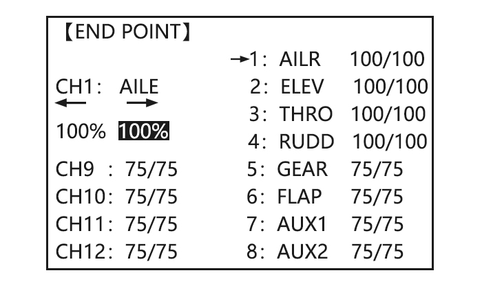
Adjustability:
• Can set each direction independently.
• Ranges from 0% (no servo movement at all) to 140%. At a 100% setting, the
Throw of the servo is approximately 40°for channels 1-4 and approximately 55°for channels 5-8.
• Reducing the percentage settings reduces the total servo throw in that direction.
Examples:
• Adjust the throttle high end to avoid binding at the carburetor, and low end to allow for proper carburetor closure.
• END POINT may be adjusted to 0 to keep a servo from moving one direction, such as flaps not intended to also operate as spoilers.
• Retract servos are not proportional. Changing END POINT will not adjust the servo.
END POINT adjusts only the individual servo. It will have no effect on any other servo that is operated in conjunction with this servo via mix or preset programming such as FLAPERON, AILEVATOR, etc. This is so that each individual servo can be carefully fine-turn to avoid binding and other conflicts. To adjust the total travel of a function such as FLAPERON, make the adjustments in that function’s controls. For CCPM helicopters, adjust the total travel of the function, such as collective pitch, in SWASH AFR. Adjust the linkage or the END POINT? It is nearly always best to adjust your linkages to get as close as possible prior to utilizing END POINT. The higher the END POINT setting, the better position accuracy and the more servo power available at nearly any position (except if using digital servos). Higher END POINT values also mean longer travel time to reach the desired position, as you are utilizing more of the servo’s total travel. (For example, using 50% END POINT would give you only half the steps of servo travel, meaning every click of trim has twice the effect and the servo gets there in half the time). End point (and moving the linkage) = torque, accuracy, but transit time to get there.
• END POINT (instead of adjusting linkages) = travel time, but torque, accuracy.
Engine idle management: IDLE-DOWN and THR-CUT: functions which work with the digital THROTTLE TRIM to provide a simple, consistent means of engine operation. No more fussing with getting trim in just the right spot for landings or take offs! For additional engine adjustments, see THROTTLE-NEEDLE and THROTTLE DELAY.
|
Goals |
Steps |
Inputs |
|
Decrease the flap servo throw in the upward direction to 5% to allow trimming of level flight only and down travel to 85% to prevent binding. |
Open END POINT function |
|
|
Choose proper channel and move stick or Knob in direction you want to adjust and set servo throw (Ex: flap up 5%) |
|
|
|
Close |
|
Trim
【TRIM】
RESET:Execute
STEP-AILE: 4( 0)
ELEV: 4( 0)
THRO: 4( 0)
RUDD: 4( 0)
TRIM submenu: resets and adjust effectiveness of digital trims.
The AT9 has digital trims which are different from conventional mechanical trim sliders. Each TRIM LEVER is actually a two-direction switch. Each time the TRIM LEVER is pressed, the trim is changed a selected amount. When you hold the TRIM LEVER, the trim speed will increase. The current trim position is graphically displayed on the start up screen. The TRIM submenu includes two functions that are used to manage the trim options.
- Trim reset (RESET): Electronically centers the trims to their default values. Note that the SUB-TRIM settings and the trim STEP rate are not reset by this command.
- Trim step (STEP): changes the rate at which the trim moves when the TRIM LEVER is activated. It may be set from 1 to 40 units, depending on the characteristics of the MULTIROTOR. Most ordinary MULTIROTOR do well at about 2 to 10 units. Generally larger trim steps are for models with large control throws or for first flights to ensure sufficient trim to properly correct the model. Smaller trim steps are later used to allow very fine adjustments in flight.
HELI models only: OFFSET is available in the idle ups. If OFFSET is inhibited, adjustment of the TRIM LEVERS will adjust the trims for all flight conditions. If OFFSET is active, then moving the trims within any one condition will affect only that condition.
|
Goals |
Steps |
Inputs |
|
Reset trims to neutral after having adjusted all linkage. Note: this is one of the several functions for which the radio requires confirmation to make a change |
Open BASIC menu, then open TRIM submenu. |
|
|
Confirm the reset. |
|
|
|
Double the sensitivity of the AILERONTRIM LEVERS for a first flight of an aerobatic model to ensure sufficient range to trim the model for level flight. |
Adjust the size of thestep (Ex:8) |
|
|
Repeat for other channel. |
|
|
|
Close |
|
SUB TRIM
SUB-TRIM: makes small changes or corrections to the neutral position of each servo. Range is -120 to +120, with 0 setting, the default, being no SUB-TRIM.
We recommend that you center the digital trims before making SUB-TRIM changes, and that you try to keep all of the SUB-TRIM values as small as possible. Otherwise, when the SUB-TRIM is of large values, the servo’s range of travel is restricted on one side.
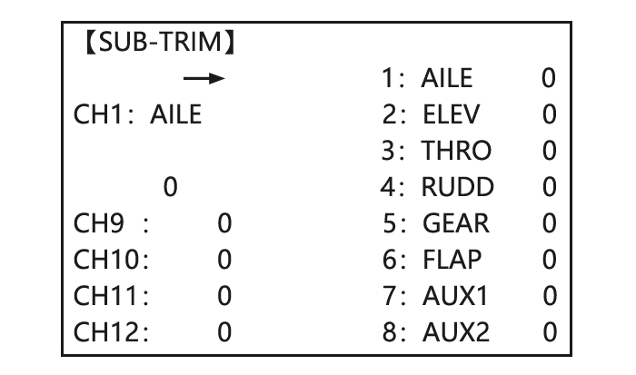
The recommended procedure is as follows:
• Measure and record the desired surface position;
• Zero out both the trims (TRIM RESET menu) and the SUB-TRIM (this menu);
• Mount servo arms and linkages so that the control surface’s neutral is as correct as possible; and
• use a small amount of SUB-TRIM to make fine corrections.
|
Goals |
Steps |
Inputs |
|
Adjust the flap servo’s SUB TRIM until its center exactly matches the aileron servo’s center as they work together as FLAPERON. |
Open BASIC menu, then open SUBTRIM |
|
|
Choose the channel to adjust until surfaces match(Ex: flap) |
|
|
|
Repeat for other channels |
|
|
|
Close |
|
Servo Reversing(REVERSE)
Changes the direction an individual servo responds to a CONTROL STICK motion.
Caution: Since channel 9 and 10 are switch only, its servo REVERSE is in the AUX-CH control screen with its switch assignment. Be sure to read the section on SWASH AFR before reversing any servos.
Except with CCPM helicopters, always complete your servo reversing prior to any other programming. If you use pre-built ACRO/ GLID functions that control multiple servos, such as FLAPERON or V-TAIL, it may be confusing to tell whether the servo needs to be reversed or a setting in the function needs to be reversed. See the instructions for each specialized function for further details.
Always check servo direction prior to every flight as an additional precaution to confirm proper model memory, hook ups, and radio functions.
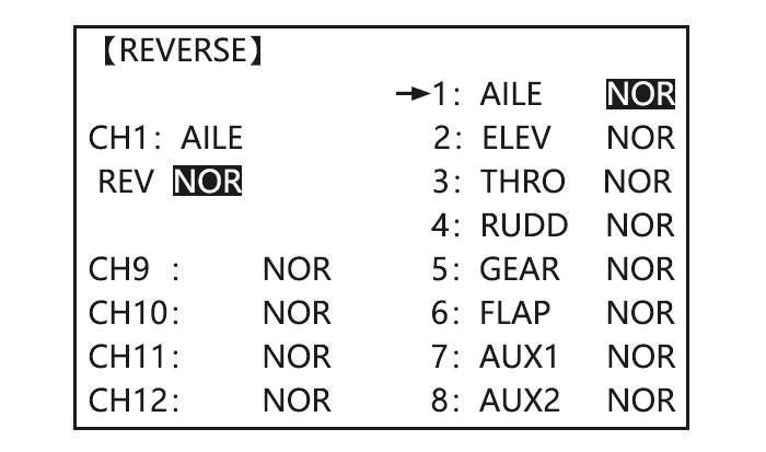
Servo reversing
|
Goals |
Steps |
Inputs |
|
Revere the direction of the elevator servo. |
Open REVERSE function |
|
|
Choose proper channel and set direction(Ex: ELEV REV)] |
|
|
|
Close |
|

Dual/Triple Rates and Exponential(D/R,EXP)
Dual/Triple Rates: reduce/increase the servo travel by flipping a switch, or (ACROGLID) they can be engaged by any stick position. Dual rates affect the control listed, such as aileron, not just a single (ex: channel 1) servo. For example, adjusting aileron dual rate will affect both aileron servos when using FLAPERON or AIL-DIF, and both aileron and elevator servos’ travel when using AILEVATOR or ELEVON or a CCPM helicopter.
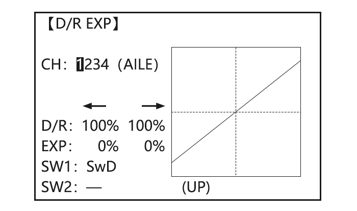
Activation:
• Any SWITCH, A-H. If you choose a 3-position switch, then that dual rate instantly becomes a triple rate.
• The glider programming offers you the choice of Condition. This option allows you to have a separate rate for each of condition. (GLID)
• Stick position (ACROGLID). (Ex: On rudder you normally use only the center 3/4 of the stick movement except for extreme maneuvers such as snaps/spins/stalls. As long as your RUDDER STICK does not exceed 90% (ie. stall turn), the rudder goes to high rate’s 90%, which is a MUCH higher amount of travel than your low rate at 89%)
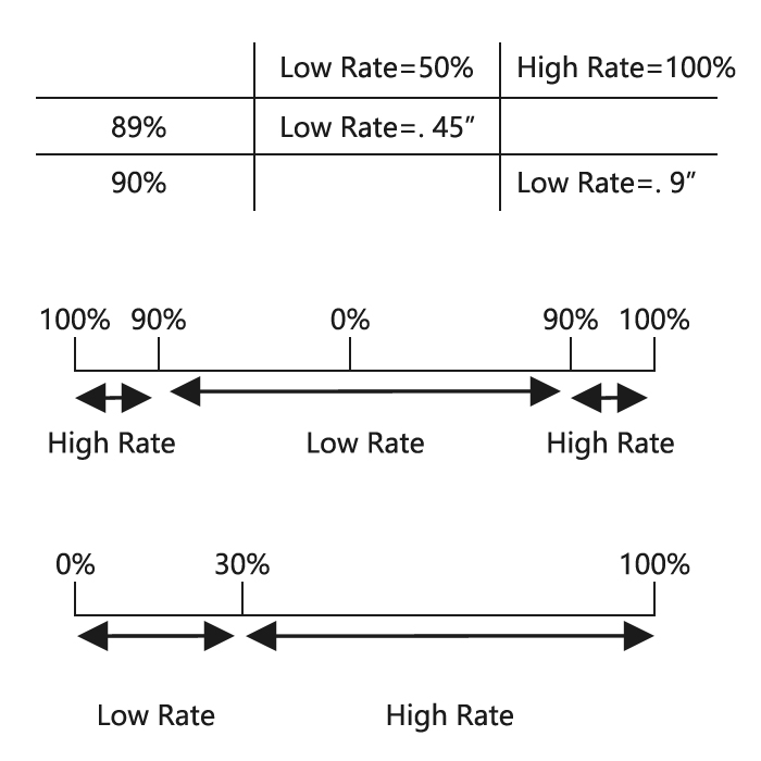
Adjustability:
• Range: 0 — 140% (0 setting would deactivate the control completely.) Initial value=100%
• Adjustable for each direction (ACRO/ GLID)
(i.e. Up/down, left/right) (Ex: Most models fly upright without any elevator trim, but require some down elevator when inverted just to maintain level flight. By increasing the down travel by the amount required to hold the model inverted, the model now has equal travel available from level upright or level inverted.
Only if any stick is chosen by the item of «SW1», a switch can also be chosen by the item of «SW2.» When operated simultaneously, the switch operation has priority over the stick operation. (ACRO)
Exponential:
Change the response curve of the servos relative to the stick position to make fly more pleasant. You can make the servo movement less or more sensitive around neutral for rudder, aileron, elevator, and throttle (except HELI type use THROTTLE CURVE instead). (ACRO type throttle EXP and THROTTLE CURVE can not be activated simultaneously). Many models require a large amount of travel to perform their best tricks.
However, without exponential, they are touchy around neutral, making them unpleasant to fly and making small corrections very difficult. Additionally, by setting different exponentials for each rate, you can make the effectiveness of small corrections similar in each rate, as in our example below:
The best way to understand exponential is to try it:
• Having made no changes yet in the D/R, EXP screen, move SWITCH D to DOWN (toward the AILERON STICK).
• Move SWITCH D up. Hold the AILERON STICK at 1/4 sticks and moves SWITCH D down.
• Notice how much less travel there is.
• Go to 3/4 stick and repeat. Notice how the travel is much closer, if not identical.
Adjustability:
• More sensitive around neutral. (Positive exponential)
• Less sensitive around neutral. (Negative exponential)
• Adjustable for each direction. (ACRO/GLID)
For throttle, exponential is applied at the low end to help nitro and gasoline engines have a linear throttle response, so that each 1/4 stick increases engine RPM 25% of the available range. (In most engines this ranges from 5-60%)
Special note for helicopters: Helicopter model types have just a single rate for each switch position rather than a rate for each side of the servo’s travel per switch position. Additionally, setting the D/R, EXP for each switch position requires cursor back to the No. setting and changing the switch position here. Just flipping the switch does not affect the screen setting, allowing dual rates to be assigned with idle-up and other features on certain switches, and does not require putting the model in that condition to make modifications.
Special note for conditions: The helicopter and glider programming offers you the choice of COND. This option allows you to have a separate rate for each of the 3 controls automatically selected when changing conditions, for a total of FIVE rates available. Simply change the switch choice to COND. and then:
(HELI) press the CURSOR LEVER to toggle through the 5 conditions while setting the rates.
(GLID) activate the corresponding condition to edit the rates.
|
Goals |
Steps |
Inputs |
|
Set up dual rates and exponential in HELI model. |
Open D/R,EXP |
|
|
Choose channel |
|
|
|
Choose first channel position |
|
|
|
Set rate and EXP(Ex: High rate=95%,0%exponential) |
|
|
|
Go to 2nd switch position and set rate and exponential. |
|
|
|
Optional: if using a 3 position switch, set 3rd rate. |
|
|
|
Optional: assign dual rates to have one for each condition. |
|
|
Goals |
Steps |
Inputs |
|
Set up aileron triple rates on SWITCH C with travel settings of 75%(normal) 25%(slow roll)and 140% (extreme aerobatics)and exponential setting of 0%, +15%, and -40% respectively. NOTE: This normal rate has no exponential so it has a Very linear, normal feel. This is slow roll rate has positive exponential (the opposite of what most people normally uses), which makes the servos more responsive around center. This makes the servos feel the same around center in the normal and low rates, but still gives a very slow roll rate at full stick. 3D rate (extreme aerobatics) has a very high distance of travel nearly twice that of the normally rate. Therefore, using a very high rate negative exponential setting softens how the servos responses around center stick. |
Open D/R,EXP |
|
|
Choose channel to change |
|
|
|
Optional: Change switch position. |
|
|
|
Confirm switch is in desired position and set rate.(Ex: up=high rate,75%) |
|
|
|
Move Switch to 2nd rate position and set this particular rate (Ex: center=low rate,25%) |
|
|
|
Optional: If using a 3 position SW, move SW to 3rd position and set this rate.(Ex: DOWN=3D rate, 140%) |
|
|
|
Optional: except using a switch, you can set high rates to be triggered when the stick moves past a certain point. To test this, set aileron high rate to 25%.Now set switch assignment to AIL (90%). Move AILERON STICK to the right and notice the huge jump in travel after the stick moves 90% of its distance. |
|
|
|
Set each rate’s EXP. |
Repeat to set low rate EXP to -40%. |
|
|
Repeat above steps for elevator and rudder. |
||
|
Close |
|


Throttle Cut
【THR CUT】
MIX:INH
RATE: 0%
THR:5%(100%)
SW:SwH
POST:DOWN
AEROBASIC
Throttle cut (THR-CUT) (ACRO0/HELI): provides an easy way to stop the engine by flipping a switch (with THROTTLE STICK at idle). The movement is largest at idle and disappears at high throttle to avoid accidental dead sticks. In HELI, there is an additional setting.
The switch’s location and direction must be chosen. It defaults to NULL to avoid accidentally assigning it to a switch, which might result in an unintentional dead stick in flight.
|
Goals |
Steps |
Inputs |
|
Decrease the throttle setting (at idle) to stop the engine with the flip of a switch.(NOTE that you MUST assign a switch. The default is NULL. We recommend SWICH C in the down position, with IDLE-DOWN programmed to SWITCH C in the center and down position.) |
Open BASIC menu, then Open THR CUT |
|
|
Activate the function .Choose desired switch, and the position which activates the function. |
|
|
|
With Throttle Stick at idle, adjust the rate. |
|
|
|
Until the engine consistently shuts off but throttle linkage is not binding. |
|
|
|
Close |
|
* Also LOGIC SW(Lsw1 to 3) may be assigned.
** Normally, a setting of 10-20% is sufficient. Viewing the carburetor barrel until it fully closes is adequate to get an approximate setting; then test with engine running to confirm.
GLIDER
Provides an easy way to stop the engine by flipping a switch no matter where the air brake stick is. The movement of servo will be -30%. Now you must select switch position and direction. Factory setting the position is NULL to avoid an accident setting on a switch to cause glitches during flight.
Adjustability:
• Range: -30% to +30%. Movement of servo is 0%, air brake stick is on its min and -30% on the max.
• SWA-H and logic switch Ls1-3 is selectable
• All position is available for logic switch including NULL (usually MIX OFF), you can set MIX by different position of a switch (UP & CEN, CEN & DN) and also NORM, REV.
|
Goals |
Steps |
Inputs |
|
Flip switch to decrease the rate until engine stops. (NOTE: you MUST assign a switch to control which default is NULL) |
Open BASIC menu ,then open THR CUT |
|
|
Activate the function Choose desired switch, and the position. |
|
|
|
Adjust Rate until the engine shuts off. |
|
|
|
Close |
|
HELICOPTER
This function is used to stop engine after flight is finished. You can set engine powered on/ off, without shifting trim stick to power off and set again every time before flight. Throttle shut for helicopter includes THR ON/ OFF (position above idle down). Before resetting throttle cut, throttle stick must keep below setting point to avoid a sudden speeding up.
Notification: trigger point setting step: under the menu THR CUT, choose THRO by DIAL, and press PUSH and move the throttle stick to trigger point, then press and hold PUSH one second to save. This function only when the throttle stick moves below trigger point.
IDLE DOWN(ACRO only)
【IDLE DOWN】
MIX:INH
RATE: 0%
SW:SwC
POST:Ct&Dn
Lowers the engine idle for: set for sitting on the runway prior to take off, stalls and spins, and landings. The normal idle setting is a little higher for easier starts and safe flights with less risk of dead sticks.
Important note: The IDLE-DOWN function is not normally used when starting the engine, and its accidental operation may keep your engine from starting. The AT9 warns that IDLE-DOWN is on when the transmitter is turned on. Be sure to turn off the function, or override the warning by pressing CURSOR lever if you intended the function to be on.
This may be assigned to any switch/position. Some modelers accidentally assign IDLE-DOWN to one side of a switch and THR-CUT to the other. There is no «normal» setting to start the engine. By default IDLE-DOWN is get to SWITCH C center and down. This works well with THR-CUT also on SWITCH C down. The SWITCH C up is normal flight/starting, center for slower maneuvers/landing, and down to cut the engine. If you assign IDLE-DOWN or THR-CUT to the spring-loaded TRAINER SWITCH H or F, then use the trainer function, you may risk loss of throttle control or dead stick for your student.
|
Goals |
Steps |
Inputs |
|
Decrease the throttle setting to idle with the flip of a switch for spins and landings. |
Open BASIC menu,open IDLE DOWN |
|
|
Activate the function |
|
|
|
Adjust the rate until engine idles as desired with Throttle stick. |
|
|
|
Optional:change switch assignment . |
|
|
|
Close |
|
*Normally a value of 10- 20%. Secure the fuselage, engine running. Set the THROTTLE STICK to idle. Adjust the IDLE-DOWN switch ON and OFF until the desired idle is achieved. Be sure to throttle up periodically to allow the engine to “clean out” and idle reliably.
*Also LOGIC SW (Lsw1 to 3) may be assigned.
Fail Safe(F/S)
(loss of clean signal and low receiver battery) submenu (F/S): sets responses in case of loss of signal or low Rx Battery.
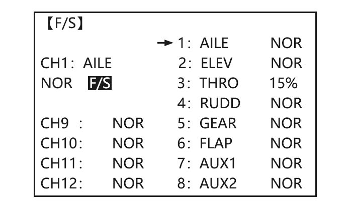
Adjustability:
•Each channel may be set independently.
• The NOR (normal) setting holds the servo in its last commanded position.
• The F/S (Failsafe) function moves each servo to a predetermined position.
• NOTE: the setting of the throttle’s F/S also applies to the Battery F/S.
• The F/S is used in certain competitions to spin the MULTIROTOR to the ground prior to flying away and doing potential damage elsewhere. Conversely, may also be used to go to neutral on all servos, hopefully keeping the plane flying as long as possible.
• Competition modelers often maintain the NOR function so that brief interference will not affect their model’s maneuver.
• Set the throttle channel so that the engine idles when there is interference (ACRO). This may give enough time to fly away from and recover from the radio interference and minimize damage if crashed.
• For helicopters, NOR is typically the safest choice.
•We also recommend setting a gasoline engine’s electronic kill switch to the OFF position in the F/S function for safety reasons.
If you specify a F/S setting, the Failsafe data is automatically transmitted once each two minutes. (PCM) When you choose the F/S mode, check that your settings are as desired by turning off the transmitter power switch and verifying that the servos move to the settings that you chose. Be sure to wait at least two minutes after changing the setting and turning on the receiver power before turning off the transmitter to confirm your changes have been transmitted.
|
Goals |
Steps |
Inputs |
|
Change the receiver Failsafe command for channel 8(gasoline engine kill switch) to a preset position. NOTE: This is one of several functions for which the radio requires confirmation to make a change. |
Open BASIC menu, then Open F/S. |
|
|
Choose channel to change(Ex:CH.8) |
|
|
|
Set and confirm fail safe command. |
|
|
|
Repeat as desired |
||
|
Close |
|
Auxiliary Channel Function
•Auxiliary channel: The auxiliary channel switch is used to do some auxiliary functions, such as opening or closing the throwing chamber, opening or closing the control machine that releases smoke, etc. Each auxiliary channel can be customized with any switch, slider or knob to control (The slider knob is usually used in the pan/tilt camera), or multiple channels can be set on the same switch, slider or knob, and the setting effect can be viewed on the’rudder amount display’ interface of the remote control.
Vehicle and ship models generally have 2 basic channels, and airplane models generally have 4 basic channels. All channels except for the basic channels of the remote control are auxiliary channels.
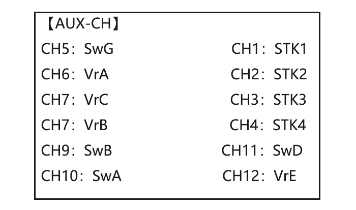
AT9S Pro can not only customize the auxiliary channels, but also customize the 4 basic channels to meet the personalized needs of model friends to a greater extent. The specific setting methods are as follows:
Long press the Mode button for 1 second to enter the basic menu, turn the PUSH button to select’System Settings’, tap the Push button for 1 second to enter the’System Settings’ menu, then select the’Joystick Mode’ to «—», tap End once Key to return to the basic menu interface, and then use the PISH key to select «auxiliary channel» to see the following interface.
Related channels:
GYRO SENSE (ACRO): CH5, 7, or 8
GYRO SENSE (HELI): CH5
GOVERNOR (HELI): CH7, or CH7 and 8
THR-NEEDLE (ACROHELI): CH8
Remember that if you assign primary control of a channel to a switch which you later use for other functions (like dual/triple rates or airbrakes), every time you use that other function you will also be moving the auxiliary channel.
|
Goals |
Steps |
Inputs |
|
Assign flaps to the right slider[VR(E)] and set channel 7 to NULL in preparation to use it as a smoke system control (the smoke system being activated later by a throttle to CH7 MIX). |
Open BASIC menu, then to AUX-CH |
|
|
Choose channel to change (Ex:CH6) |
|
|
|
Repeat above steps as desired. (Ex:CH7=NULL) |
|
|
|
Close |
|
GOVERNOR (HELI): CH7, or CH7 and 8
THR-NEEDLE (ACROHELI): ch. 8
Remember that if you assign primary control of a channel to a switch which you later use for other functions (like dual/triple rates or airbrakes), every time you use that other function you will also be moving the auxiliary channel.
TIMER Submenu
Controls three electronic clocks used to keep track of time remaining in a competition time allowed, flying time on a tank of fuel, amount of time on a battery, etc.
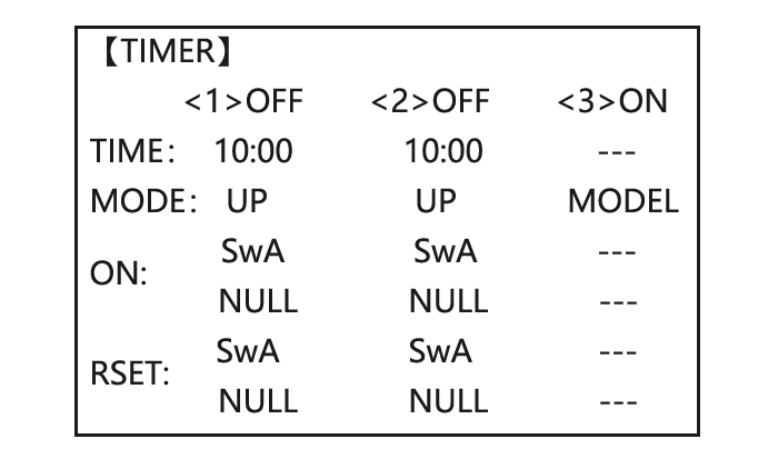
Adjustability:
• Count down timer: starts from the chosen time, displays time remaining. If the time is exceeded, it continues to count below 0.
• Count up timer: starts at 0 and displays the elapsed time up to 99 minutes 59 seconds.
• Count down timer (Stop type): starts from the chosen time, displays time remaining, and stops at 0.
• Model timer: cumulates ON time up to 99 hours 59 minutes each model. Once Model timer function is turned off, the cumulate time will also be reset to «0:00».
• Independent to each model, and automatically updates with model change.
• In either TIMER mode, during the last twenty seconds, there’s a beep each second. During the last ten seconds, there’s two beeps each second. A long tone is emitted when the time selected is reached. (UP/DOWN TIMER)
• To Reset, choose the desired timer with the CURSOR lever (while at the startup screen), then press and hold DIAL for 1 second.
• Activation by either direction of SWITCH A-H, by THROTTLE STICK (STK-THR) (Using the THROTTLE STICK is convenient if you are keeping track of fuel remaining, or for an electric, how much battery is left), by LOGIC SWITCH Lsw1-Lsw3 or by the power SWITCH (PWR SW).
|
Goals |
Steps |
Inputs |
|
Set timer 2 to count down 4 1/2 minutes, being controlled by Throttle Stick position. This utilized to keep track of actual Throttle on time to better cooperate with fuel/battery usage. |
Open BASIC menu, then to TIMER |
|
|
Go to TIMER <2> |
|
|
|
Adjust time to 4min.30sec., count down |
|
|
|
Assign switch at ST-THK and set trigger point. |
|
|
|
Close |
|
• Also the reset switch can be assigned (SWITCH A-H or LOGIC SWITCH Lsw1-Lsw3)
TRAINER
For training novice pilots with optional trainer cord connecting 2 transmitters. The instructor has several levels of control.
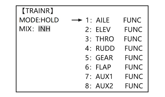
Adjustability:
• NORM: When the TRAINER SWITCH is ON, the channel set to this mode can be controlled by the student. The set channel is controlled according to any programming set at the student’s transmitter.
• FUNC: When the TRAINER SWITCH is ON, the channel set to this mode can be controlled by the student, controlled according to any mixing set at the instructor’s transmitter.
• MIX: When the TRAINER SWITCH is ON, the channel set to this mode can be controlled by both the student and the instructor, controlled according to any mixing set at the instructor’s transmitter. And the student’s mixing rate is adjustable. (Default 30%)
[Note] However, it becomes invalid even if it sets up the channel which is not in a student’s transmitter. The channel serves as operation by the instructor’s transmitter automatically.
• OFF: The channel set to this mode cannot be controlled by the student even when the TRAINER SWITCH is ON. The set channel is controlled by the instructor only, even when the TRAINER SWITCH is ON.
• SWITCH: controlled by spring-loaded SWITCH H only. Not assignable.
• Compatibility: The AT9S Pro may be master or student with any Radiolink transmitter compatible with the cord. Simply plug the optional trainer cord (For AT9S Pro series, sold separately) into the trainer connection on each transmitter, and follow the guidelines below.
EXAMPLES:
•When throttle/collective is set to FUNG, 5-channel helicopter practice is possible with a 4-channel transmitter.
• Set up the model in a second transmitter, use NORM mode to quickly and safely check proper operation of all functions, and then allow the student radio to fully fly the model.
• Using NORM mode, set lower throws, different exponentials, even different auxiliary channel settings on the student radio (if it has these features).
• To ease the learning curve, elevator and aileron may be set to the NORM or FUNC mode, with the other channels set to OFF and controlled by the instructor.
NOTE:
• NEVER turn on the student transmitter power.
•ALWAYS set the student transmitter modulation mode to PPM.
• BE SURE that the student and instructor transmitters have identical trim settings and control motions. Verify by switching back and forth while moving the control sticks.
• FULLY extend the instructor’s antenna. Collapse the student’s antenna. (Except 2.4GHz)
• When the TRAINER function is active, the snap roll function is deactivated. Other functions, such as IDLE-DOWN and THR-CUT, which have been assigned to the same switch, are not deactivated. Always double check your function assignments prior to utilizing the TRAINER function.
•When you select a different model, the TRAINER function is deactivated in the current model for safety reasons.
|
Goals |
Steps |
Inputs |
|
Turn on the TAINER system and set up so student has :fully functional control of aileron and elevator to support FLAPERON &AILERON; normally control of rudder to allow lowered travel; and no throttle channel control(with the instructor for safety) |
Open BASIC menu, then Open TRAINER |
|
|
Activate TRAINER |
PUSH, |
|
|
Choose desired channels and proper training types |
|
|
|
Close |
|
|
|
Test student radio function prior to attempting to fly! |
Logic Switch Selection(LOGIC SW)
The various functions in the AT9S Pro can be selected by switch..
The Logic switch can be assigned to the functions as following: THR-CUT, IDLE DOWN, AUX-CH, TIMER, PROG. MIX, AIRBRAKE, ELEV-FLAP, and AILE-FLAP. The logic switch can activate functions by two switches combination. The 2 types of logic, either AND or OR, can be selected.
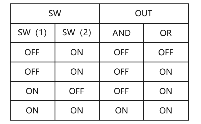
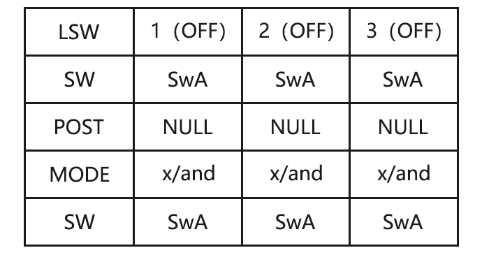
Adjustability:
• Three logic switches can be used. (LSW1, LSW2, and LSW3 )
• SW (1): Any SWICH A-H or THRSTKS, SW (2): Any SWICH A-H
• Switch position (POSI)
• Logic mode: AND or OR (MODE)
SERVO Display and Cycle Submenu
Displays radio’s output to channels 1-12(defualt 10 channels, you can upgrade firmware to 12 channels)
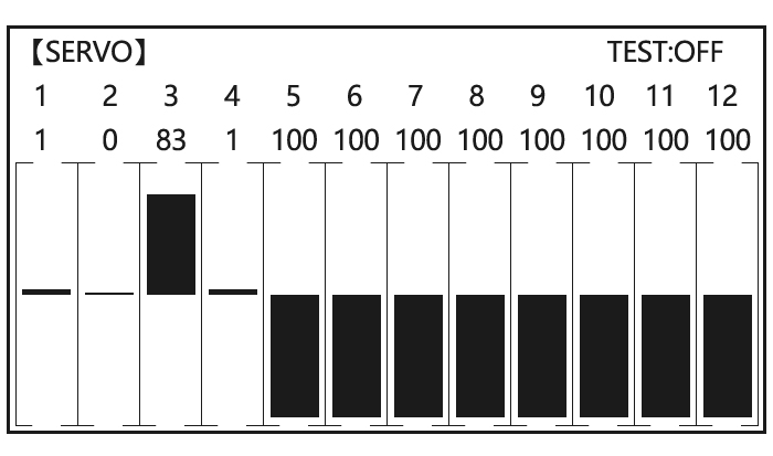
The servo submenu includes two features:
• Real-time bar-graph display to demonstrate exactly what commands the transmitter is sending to the servos. (This can be particularly handy in setting up models with complicated mixing functions, because the results of each stick, lever, knob, switch input and delay circuit may be immediately seen.)
• Servo cycle function to help locate servo problems prior to in-flight failures. (Channels 1-8)
|
Goals |
Steps |
Inputs |
|
View the result of reassigning channel 6 from VR(A) knob to three-position SWITCH C |
Complete desired programming function.(Ex: in AUX-CH,move ch.6 to SWITCH C) |
See AUX-CH for details. |
|
Open SERVO function |
|
|
|
Move each control to see the operation.(Ex: SWITCH C in all positions) |
|
|
|
Prepare all servos to be cycled and cycle |
Plug in servos. Power on. |
|
|
Close |
|
TELEMETRY
Signal strength and receiver voltage integrated into the radio transmitter. It is displayed as the following configure, also it is in the sub menu RECEIVE.
Receiver voltage is shown as RX,
External voltage is shown as EXTY.
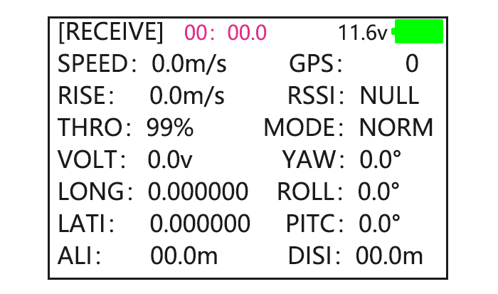
Find telemetry information: under BASIC MENU, select RECEIVE, presses PUSH to enter, you can find the telemetry info, shown as below. RX is receiver voltage, EXT is external voltage. Also temperature and engine speed (EXT, TEMPERATURE, RPM, and GPS all need telemetry sensor).
RSSI is signal strength, NULL is for no signal, and 0 is for max.
Connection of telemetry sensor: sensor of EXT, TEMPERATURE, RPM, GPS can connect one by one with the receiver port DATA.
Connection between R9DS and telemetry module PRM-01(picture below on left)

Connection between R9DS and OSD telemetry module PRM-03 with PIXHAWK (picture below on right)
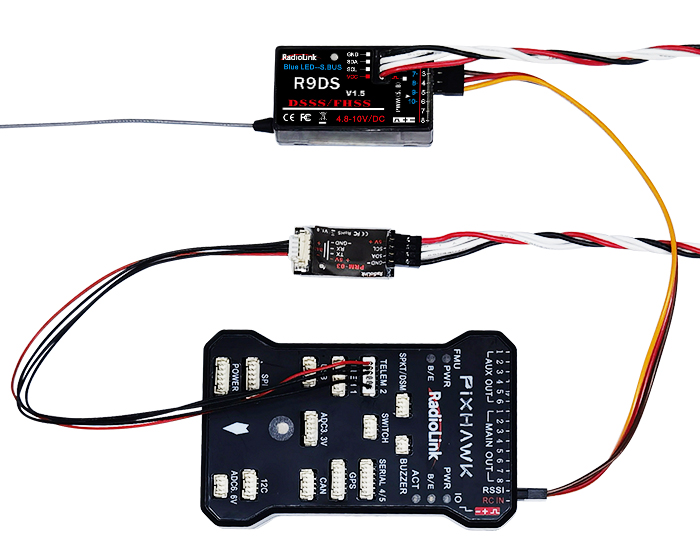
ACRO Advance Functions
Airplane Wing Types(ACRO/GLID)
There are 3 basic wing types in MULTIROTOR models:
• Simple. Model uses one aileron servo (or multiple servos on a Y-harness into a single receiver channel) and has a tail. This is the default setup and requires no specialized wing programming.
• Twin Aileron Servos. Model uses 2 aileron servos and has a tail. See TWIN AILERON SERVOS.
• Tail-less models (flying wing). Model uses 2 wing servos working together to create both roll and pitch control. See ELEVON.
Twin Aileron Servos (with a tail) (ACRO/GLID): Many current generation models use two aileron servos, plugged into two aileron servos, plugged into two separate receiver channels. (If your model is a flying wing without separate elevators, see ELEVON)
ADVANTAGE:
• Ability to adjust each servo’s center and end points for perfectly matched travel.
• Redundancy, for example in case of a servo failure or mid-air collision.
• Ease of assembly and more torque per surface by not requiring torque rods for a single servo to drive 2 surfaces.
• Ease of assembly and more torque per surface by not requiring torque rods for a single servo to drive 2 surfaces.
• Having more up aileron travel than down travel for straighter rolls, aileron differential. (See glossary for definition.)
• Set a negative percentage to reverse the operation of one of the servos.
Options:
• 5-channel receiver. Set up AILE-2 prior to continuing with FLAPERON or AIL-DIFF.
• FLAPERON:
•Uses CH6 for the second servo
• Allows flap action as well as aileron action from the ailerons.
• Provides FLAP-TRIM function to adjust the neutral point of the FLAPERON for level flight.
• Also allows aileron differential in its own programming (instead of activating AIL-DIFF).
• Uses CH7 for the 2nd servo (see AIL-2 use CH5)
• Leaves CH5 & CH6 free for flap operation, such as FLAPERON and flap action together, in AIRBRAKE.
• Allows for more up aileron travel than down for straighter rolls. You will need to choose which of FLAPERON or AIL-DIFF is better for your model’s setup. If you need the ailerons to also operate as flaps, you most likely want to use FLAPRON. If your model has 2 aileron servos and flaps, then AIL-DIFF is probably the easiest choice.
NOTE: Only one of the three wing-type functions (FLAPERON, AIL-DIFF, and ELEVON) can be used at a time. All three functions cannot be activated simultaneously. To activate a different wing type, the first must be deactivated.
Twin Aileron Servos
AILE-2 allows FLAPERON and AIL-DIFF with a 5-channel receiver. AILE-2 only tells the radio that you are using CH5 and CH6 (FLAPERON), or CH5 and CH7 (AILDIFF), not CH6 or CH7, as the second servo in FLAPERON or AILE-DIFF. You still must activate and set up the FLAPERON/AILE-DIFF function.
Note that selecting CH6&5 or CH7&5 does NOT free up CH6 or CH7 to be used for other functions when using a receiver with more than 5 channels. Both 5 and 6 (FLAPERON/AILE-DIFF) are dedicated to the FLAPERON or AILE-DIFF programming. [This is beneficial with four aileron servos that need to have their end points or sub-trims set separately. CH1, CH5 and CH6 are already fully set up to operate as ailerons. Mix the CH7 or CH8 (the second aileron servo on the other side) into ailerons to function properly.
|
Goals |
Steps |
Inputs |
|
Adjust the 2nd aileron servo output from CH6or7 to channel CH6&5 Allow twin aileron servos operating with a 5-channel receiver. |
Open PARAMETER submenu. |
|
|
Select AILE-2 and change to CH6&5. |
|
|
|
Close |
|
There are 4 basic tail types in MULTIROTOR models:
• Simple. Model uses one elevator servo and one rudder servo (or multiple servos on a Y-harness). This is the default.
• Dual Elevator servos. Model uses 2 elevator servos.
• Tail-less models. Model uses 2 wing servos together to create roll and pitch control. See ELEVON (ACRO/ GLID 1A+1F).
• V-TAIL. Model uses 2 surfaces, at an angle, together to create yaw and pitch control. see V-TAIL (ACRO/ GLID).
Note: Only one of the three tail-type functions (AILEVATOR, V-TAIL, and ELEVON) can be used at a time. The radio provides a warming and will not allow the activation of another tail type until the first is deactivated. An error message of OTHER WING MIXING IS ON will display.
Using ELEVON (ACRO/GLID 1A+1F): it is used with delta wings, flying wings, and other tailless MULTIROTOR that combine aileron and elevator functions, using two servos, each one on the ELEVON. The aileron/elevator responses of each servo can be adjusted independently. This is also popular for ground model use, such as tanks, which drive two motors together for forward, and one motor forward/ one backward for turning.
ACRO Advance Menu
Mixes are special programs within the radio that command one or more channels to act together with input from only one source, such as a stick, slider or knob.
There are a variety of types of mixes:
TYPE:
• Linear: Most mixes are linear. A 100% linear mix tells the slave servo to do exactly what the master servo is doing, using 100% of the slave channel’s range to do so. An example is FLAPERON, when aileron stick is moved, the flap servo is told to move exactly the same amount. A 50% linear mix would tell the slave servo, for example, to move to 50% of its range when the master’s control is moved 100%.
• Offset: An OFFSET mix is a special type of linear mix. When the mix is turned on (usually a flip of a switch), the slave servo is moved a set percent of its range. An example of this is AIRBRAKE, moving flaps, FLAPERON, and elevator all to a set position at the flip of a switch.
• Curve: Curve mixes are mostly used in helicopters, but may also be used in airplanes and gliders. An example is THROTTLE-NEEDLE mixing, where the in-flight needle’s servo is moved, changing the mixture, as the throttle servo is moved.
• Delay: Delay mixes are part of a few very special functions that make the servo move to its desired range more slowly.
THROTTLE DELAY (simulates turbine engines) and the elevator delays in AIRBRAKE are two examples of this. DELAY in HELI is another example that slows the servo movement to the trim settings for the other conditions.
Essentially every feature in the radio’s programming is really a mix, with all assignments/programming set up and ready to use. Additionally, the AT9 ACRO and GLID programs both provide 4 linear and 4 curve fully-programmable mixes ( HELI provides 4 linear and 2 curve) that allow you to set up special mixes to resolve flight difficulties, activate additional functions, etc.
Let’s look quickly at a few examples that are features we’ve already covered. This may help to clarify the mix types and the importance of mixes:
Additional example:
• Exponential is a preprogrammed curve mix that makes the servos’ response more (+) or less (-) sensitive around center stick (works in conjunction with dual rate, a linear mix that adjusts the total range). see D/R,EXP,
• IDLE-DOWN and THR-CUT are two OFFSET pre-programmed mixes. These tell the throttle servo, when below a certain point, to move toward idle an additional set percentage to help close the carburetor.
• ELEV-TO-FLAP mixing is a pre-programmed linear mix to move the flaps proportionally to elevator control, helping the model loop even tighter than it can on elevator alone.
• THROTTLE-NEEDLE mixing is a curve mix (like PROG.MIX 5 to  for proper in-flight needle setup.
• THROTTLE DELAY mixing is a pre-programmed delay mix that slows down the response of the CH3 servo.
Next, we’ll get an in-depth look at some pre-programmed mixes (mixes whose channels are predefined for simplicity) we’ve not covered yet, and last, look at the fully-programmable mix types.
Program MIX
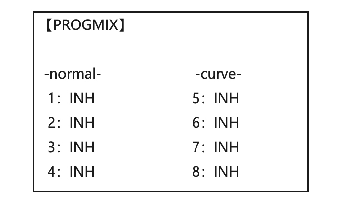
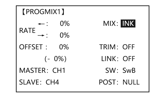
AT9S Pro contains four separate linear programmable mixes. (Note that mixer #5-8’s mixing RATE are set with a 5-point curve. HELI has mixer #5-6’s mixing. See CURVE MIXES
There are a variety of reasons you might want to use these mixes. A few are listed here. All of the adjustable parameters are listed below, but don’t let them scare you. For your first few times experimenting with mixes, just turn on the default mixes, adjust them how you think they need to be, then use the servo screen to check and see if you were correct. As with all functions, a sample
setup follows, step by step, to assist you.
Sample reasons to use linear programmable mixes:
• To correct bad tendencies of the MULTIROTOR (such as rolling in response to rudder input).
• To operate 2 or more servos for a single axis (such as two rudder servos).
• To automatically correct for a particular action (such as lowering elevator when flaps are lowered).
• To operate a second channel in response to movement in a first channel (such as increasing the amount of smoke oil in response to more throttle application, but only when the smoke switch is active).
• To turn off response of a primary control in certain circumstances (such as simulating one engine flaming -out on a twin, or throttle-assisted rudder turns, also with a twin).
Adjustability:
• Defaults: The 4 programmable mixes default to the most frequently used mixes for simplicity. If you want to use one of these mixes, simply select that mix number so that the master and slave servos are already selected for you.
• PROG.MIX1 aileron-to-rudder for coordinated turns
• PROG.MIX2 elevator-to-flap for tighter loops (HELI mixes default to ELEV-to-pitch.)
• PROG.MIX3 flap-to-elevator to compensate pitching with flaps (HELI mixes default to pitch-to-ELEV)
• PROG.MIX4 throttle-to-rudder ground handling compensation
•Channels available to mix: All four mixes may use any combination of CH1-8. (CH9-10 is not proportional and cannot be mixed.) Offset and dials may also be set to the master channels.
•Master: the controlling channel, the channel whose movement is followed by the slave channel.
•Another channel: Most mixes follow a control channel. (Ex: rudder-to-ailerons, 25%, no switch, corrects roll coupling.)
|
MASTER |
SLAVE |
LINK |
TRIM |
SWITCH |
POSITION |
RATE |
OFFSET |
|
RUDD |
AILE |
ON |
OFF |
ANY |
NULL |
25% |
0 |
•Offset as master: To create an OFFSET mix, set the master as OFST. (Ex: Move FLAPERON as flaps 20% of their total throw when SWITCH C is in down position.)
|
MASTER |
SLAVE |
LINK |
TRIM |
SWITCH |
POSITION |
RATE |
OFFSET |
|
OFST |
FLAP |
ON |
N/A |
C |
DOWN |
20% |
0 |
• Dial as master: To directly effect one servo’s position by moving a dial, set the master as the desired dial. (Ex: create a second throttle trim on left slider.)
|
MASTER |
SLAVE |
LINK |
TRIM |
SWITCH |
POSITION |
RATE |
OFFSET |
|
VR(D) |
THRO |
OFF |
N/A |
ANY |
NULL |
5% |
0 |
•Slave: the controlled channel. The channel is moved automatically in response to the movement of the master channel. The second channel is in a mix’s name (i.e. aileron-to-rudder).
•Link: Link this programmable mix with other mixes.
Ex: PMIX FLAP-ELEVATOR mixing to correct for ballooning when flaps are lowered, but model has a V-tail. Without LINK, this mix only moves CH2 elevator when flap is commanded, resulting in a dangerous combination of yaw and roll. With LINK ON, mixing is applied to both CH2 and CH4.
|
MASTER |
SLAVE |
LINK |
TRIM |
SWITCH |
POSITION |
RATE |
OFFSET |
|
FLAP |
ELEV |
ON |
OFF |
ANY |
NULL |
5% |
0 |
•Trim: Master’s trim affects slave. Not displayed if master is not CH 1-4, because 5-9 have no trim. Ex: two rudder servos. With TRIM OFF, rudder trim would bind the two servos. TRIM ON resolves this.
• On/off choices:
• SWITCH: Any of the positions of any of the 8 switches may be used to activate a mix. Up&Cntr, Cntr&Dn options allow the mix to be ON in 2 of the 3 positions of a 3-position SWITCH.
• NULL: No SWITCH can turn this mix OFF. This mix is active at all times.
• LOGIC SW (Lsw1 to 3) may be assigned.
• STK-THR: Turn on/off by THROTTLE STICK movement. Trigger point/direction are selectable. Ex: OFST-to-(gear doors) mix to open gear doors at idle, which is only active if throttle is below half.
|
MASTER |
SLAVE |
LINK |
TRIM |
SWITCH |
POSITION |
RATE |
OFFSET |
|
OFST |
AUX2 |
OFF |
ON |
STK-THR |
Stick at 1/2.for 1 sec. |
100% |
0 |
• Rate: the percentage of the slave’s range it will move upon maximum input from the master channel. Ex: RUDDERAILERON mix, 50%. Ail range=1». When rudder is moved full right, ailerons move 1/2».
|
MASTER |
SLAVE |
LINK |
TRIM |
SWITCH |
POSITION |
RATE |
OFFSET |
|
RUDD |
AILE |
OFF |
OFF |
ANY |
NULL |
50% |
0 |
• Offset: Offsets the slave’s center is relative to the master. Ex: Smoke valve opens wider per throttle servo position when smoke SWITCH is ON. Smoke servo’s neutral is moved down from THROTTLE STICK center to the bottom.
|
MASTER |
SLAVE |
LINK |
TRIM |
SWITCH |
POSITION |
RATE |
OFFSET |
|
THRO |
AUX2 |
OFF |
OFF |
E |
DOWN |
100% |
100% |
|
Goals |
Steps |
Inputs |
|
Set up a FLAP-ELEV mix: No elevator movement when flaps move up(spoilers),5%elevator movement when flaps move down. Link should be ON if mode has twin elevator servos. Otherwise, Link remains OFF. |
Open an unused programmable mix.(Ex: use PROG.MIX3 since it is already set up for FLAP-ELEVATOR) |
|
|
Activate the function |
|
|
|
Choose master and slave channels. |
Already CH6 .Already CH2 |
|
|
Optional: set Master as OFST or VR(A-E) |
|
|
|
Set LINK and TRIM as needed. |
|
|
|
Assign SWITCH and position. |
|
|
|
Optional: set switch to STK-THR to activate mix with THROTTLE STICK. |
|
|
|
Optional: set switch position to NULL. Make mix active at all time. Not complete with STK-THR. |
|
|
|
Set rate. (Ex: Lo=0%,Hi=5%) |
|
|
|
Set OFF SET, if needed.(Ex:0) |
|
|
|
Close |
|


Other samples:
• RUD-ELEV (ACRO GLID) mix: Compensate for pitching up or down when rudder is applied.
• AIL-RUD mix (ACRO): Coordinate turns by applying rudder automatically with aileron input. All model types.
• ELEV-PIT (HELI) mix: Compensate for the loss of lift of tilting the model
Curve Programmable Mixes
AT9S Pro’s ACRO/GLID programs contain four separate curve programmable mixes. HELI contains two. There are a variety of reasons you might want curve mixes. Usually a linear mix doesn’t fit your needs along the whole range. One pre-programmed curve mix is the THROTTLE-NEEDLE function. This curve is adjustable at 5 points, allowing you to adjust the motor’s tuning at 5 points along its RPM range.
One programmable curve mix defaults to RUDDER-AILERON. A linear mix that keeps the model from rolling in knife-edge is probably too much aileron when rudder is applied in level flight. Create a curve mix and set all 5 points to match the linear mix. Inhibit the linear mix, and then adjust the curve to get the right response all along the rudder channel’s travel.
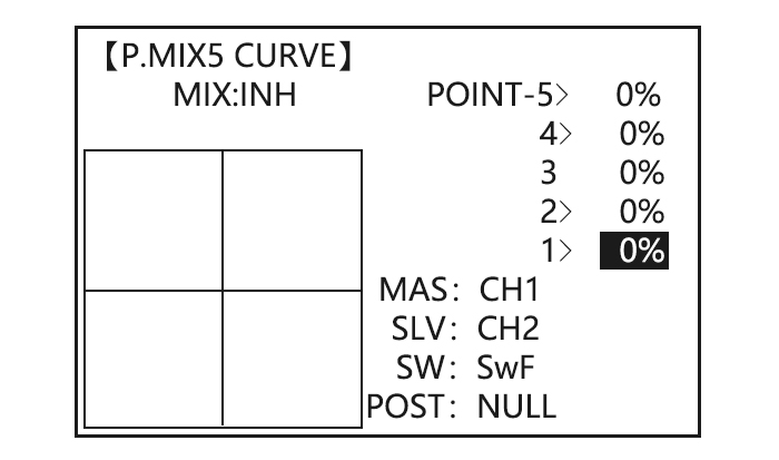
Adjustability:
• ACRO/GLID Defaults: The 4 programmable curves mixes default to the most frequent choices, but can be
set to any channel.
• PROG.MIX5 rudder-to-aileron for roll coupling compensation (GLID mixes default to aileron-to-ELEV.)
• PROG.MIX6 rudder-to-aileron for roll coupling compensation (GLID mixes default to aileron-to-ELEV.)
• PROG.MIX7 rudder-to-elevator for pitch coupling compensation (GLID mixes default to elevator-to-airbrake.)
• PROG.MIX8 rudder-to-elevator for pitch coupling compensation (GLID mixes default to elevator-to-airbrake.)
• HELI Defaults:
• PROG.MIX5 aileron-to-elevator for coordinated turns
• PROG.MIX6 aileron-to-elevator for coordinated turns
• Master: The controlling channel can only be a channel. Cannot OFFSET or dial.
• Trim: not available in curve mixes.
• Offset: not available in curve mixes.
|
Goals |
Steps |
Inputs |
|
Set up a RUDD-ELEV curve mix on a model that pitches down severely at full rudder and not at all with minimal rudder input, and pitches worse on right rudder than left: Point 1: 25% ON when SWITCHC is down. LINK should be ON if model has twin elevator servos. Otherwise, LINK remains OFF. (Note that point 3 is 0%. Otherwise, the elevator would be retrimmed when the mix is active and no rudder input is given.) |
Open an unused programmable mix.(Ex: use PROG.MIX7 since it is already set up for FLAP-ELEVATOR) |
|
|
Activate the function |
|
|
|
Choose master and slave channels. |
Already RUDD. Already ELEV |
|
|
Set LINK as needed( Ex: off) |
||
|
Assign SWITCH and position. |
|
|
|
Optional: set switch to STK-THR to activate mix with THROTTLE STICK. |
|
|
|
Optional: set switch position to NULL. Make mix active at all time. Not complete with STK-THR. |
|
|
|
Set desired percent at five stick points. |
Repeat for points 2-5. |
|
|
Close |
|
FLAPERON(ACRO/GLID 1A+1F )
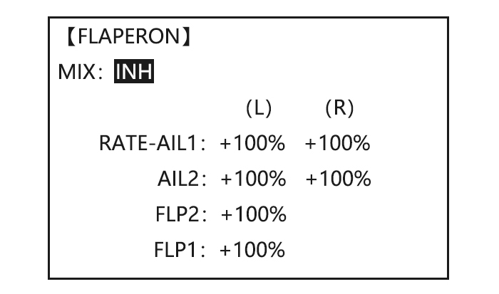
ACRO
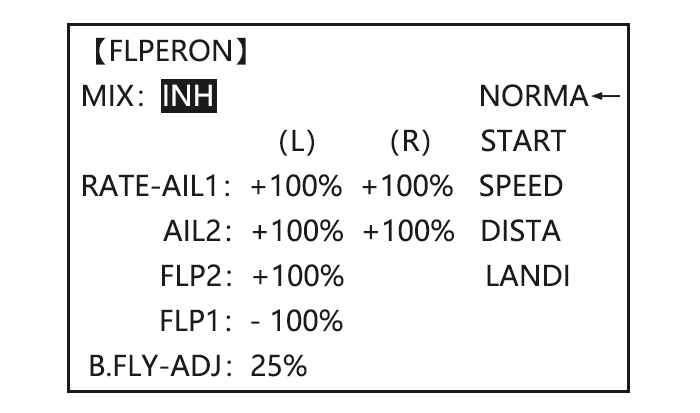
GLID
The FLAPERON mixing function uses one servo on each of the two ailerons, and uses them for both aileron and flap function. For flap effect, the ailerons raise/lower simultaneously. Of course, aileron function (moving in opposite directions) is also performed.
Note: When changing the polarity of a rate, «change rate dir?» is displayed for a check. Please set up after pressing DIAL for 1 second and canceling an alarm display. (GLID only)
Once FLAPERON is activated, any time you program CH6 or «flap» (i.e. ELEVATOR mixing), the radio commands both servos to operate as flaps. The amount of travel available as flaps is independently adjustable in FLAPERON. A trimming feature is also available (see FLAP-TRIM) to adjust both neutral positions together for straight-and-level flight or slight increases/decreases of the flap angle. END POINT and SUB-TRIM both still adjust each servo individually.
Adjustability:
• Each aileron servo up travel can be set separate from its down travel, creating aileron differential. (See example).
• Each aileron servo’s travel when actuated as a flap is separately adjustable.
• AILE-2 can be utilized to use a 5-channel receiver and still have FLAPERON. NOTE: The AILE-2 function only commands the channel 5 servo to operate with the aileron servo as ailerons, and to obey the primary flap control (travel adjusted in FLAP-TRIM.) It does not provide full flap mix capability as when using a 6+ channel receiver and channel 6.
• The separate FLAPERON settings for each condition can be set. (GLID)
Note: Activating FLAPERON only makes the ailerons work as ailerons and tells the radio how far you want them to move as flaps. If you then activate other programming that moves them as flaps.
FLAP-TRIM is the flap-trimming feature that allows the flaps to move in reaction to the channel 6 control. It is meant only for trimming the flaps’ center but can also be used as full flap control.
ELEVATOR-FLAP would add elevator mixing into the flap movement from the flap dial after FLAP-TRIM is activated.
|
Goals |
Steps |
Inputs |
|
Activate twin aileron servos, FLAPERON. |
Open the FLAPERON. |
|
|
Activate the function. |
|
|
|
Optional: adjust the up/down travel for 2 servos.(Ex:90% down) |
|
|
|
Optional: Use as total flap control. Resign CH6 is primary control in AUX-CH to desired flap control.(Ex: right slider) |
|
|
|
Close |
|
* If you receive an error message that OTHER WING MIXING IS ON, you must deactivate AIL-DIFF or ELEVON.
FLAP-TRIM
Using FLAP-TRIM to adjust FLAPERON (ACRO/GLID)
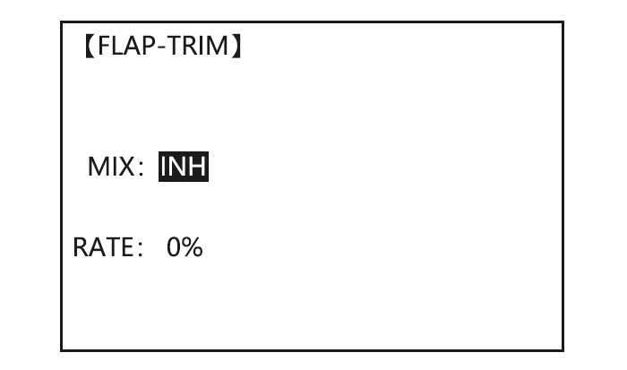
ACRO
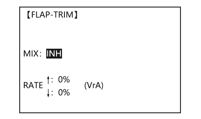
GLID
FLAP-TRIM assigns the primary FLAPERON control [defaults to VR(A)] to allow trimming in flight of the flap action of FLAPERON.
Note: Even if FLAP-TRIM is made active with AIL-DIFF, it will not have any effect. The ONLY function that allows control of the ailerons as flaps in the AIL-DIFF configuration is AIRBRAKE. Most modelers use AIRBRAKE, or programmable mixes, to move the flaps to a specified position via movement of a switch.
FLAP-TRIM may also be used as the primary flap control in flight. By doing so, you can assign CH6 to a 3-position switch, with a «SPOILERON», neutral, and «FLAPERON» position, and even adjust the percentage traveled as FLAPERON/SPOILERON by changing the Flap Trim travel.
|
Goals |
Steps |
Inputs |
|
Add FLAP-TRIM to allow the model’s ailerons to be trimmed together as flaps at any time during the flight, with a maximum travel of 5% of the total flap travel set in FLAPERON. |
Open FLAP-TRIM function |
|
|
The function is automatically activate with FLAPERON; however the default travel is 0. |
||
|
Adjust the travel available to the FLAPERON when turning the CH6 dial. |
|
|
|
Close |
|
AILE DIFF(ACRO/GLID 2A+1F/GLID 2A+2F)
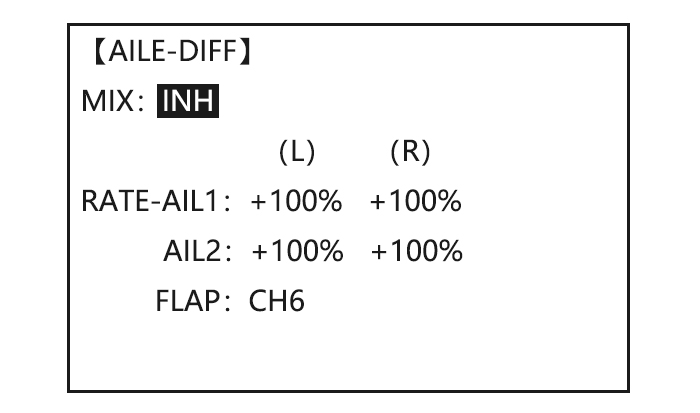
ACRO
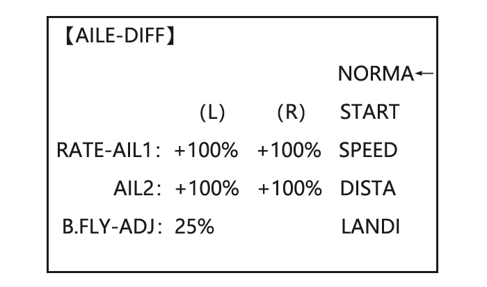
GLID (2A+1F)/GLID (2A+2F)
Aileron differential is primarily used on 3 or 4-servo wings, with one servo operating inboard flap on CH6 or CH5 & CH6, and AILE-DIFF controlling proper aileron operation of 2 aileron servos, plugged into CH1 and CH7. The ailerons can not be moved like flaps when using AILE-DIFF, except if using AIRBRAKE. (Note that even if you make FLAP-TRIM active while using AILE-DIFF, it will not have any effect. ONLY AIRBRAKE controls the ailerons as flaps in the AILE-DIFF configuration.)
Note: When changing the polarity of a rate in camber-flap, «change rate dir?» is displayed for a check. Please set up after pressing DIAL for 1 second and canceling an alarm display. (GLID only)
• FLAP function allows you to set up 1 or 2 servos for flap action.
• The separate AILE-DIFF settings for each condition can be set. (GLID only)
|
Goals |
Steps |
Inputs |
|
|
Activate twin aileron servos using AILE-DIFF. |
Open the FLAPERON. |
|
|
|
Activate the function. |
|
||
|
Optional: adjust the up/down travel for 2 servos..(Ex:90% down) |
|
||
|
Close |
|
||
* If you receive an error message that OTHER WING MIXING IS ON, you must deactivate ELEVON or FLAPERON.
Air Break(ACRO/GLID)
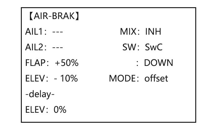
ACRO
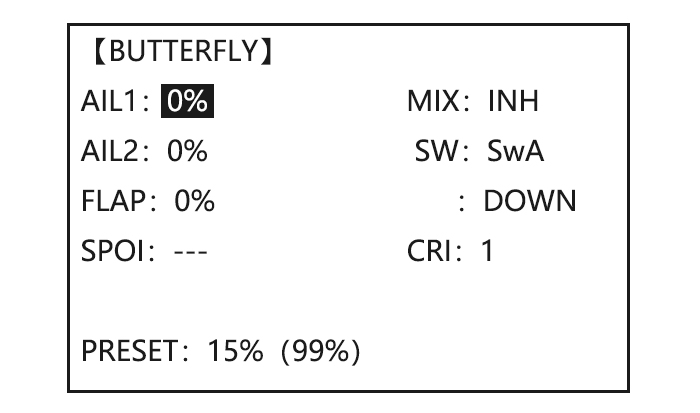
GLID

Like FLAPERON and AILEVATOR, AIRBRAKE is one function that is really made up of a series of pre-programmed mixes all done for you within the radio. AIRBRAKE (often called «crow» or BUTTERFLY — see GLID, p. 62 for details) simultaneously moves the flap (if installed), twin ailerons (if installed) and elevator, and is usually used to make steep descents or to limit increases in airspeed in dives.
This function is often used even on models without flaps as an easy way to use the FLAPERON and FLAP-ELEVATOR mixing together.
Adjustability:
• Activation: be proportional by moving the THROTTLE STICK, or set positions by flipping the assigned switch.
• Switch: Mix SWITCH is selectable.
• Also LOGIC SW (Lsw1 to 3) may be assigned.
• Linear(Inversely proportional to THROTTLE STICK): Provides a proportional increase in amount of AIRBRAKE action as THROTTLE STICK is lowered and assigned switch is on. It provides gradually more AIRBRAKE as you slow the engine. Includes selectable stick position where AIRBRAKE begins, gradually increasing to the same setting as the THROTTLE STICK is lowered. If you would like to have the airbrake be directly proportional to throttle stick, you will
need to reverse the THR-REV function. Note that this changes the throttle stick direction for all models.
• Offset: Provide AIRBRAKE response immediately upon switch movement, going to a pre-set travel on each active channel without any means of in-flight adjustment.
• During Airbrake operation, the elevator travel is displayed on the elevator trim display in the Startup screen.
•Delayed reaction: You can suppress sudden changes in your model’s attitude when AIRBRAKEBUTTERFLY is activated by setting the delay (delay-ELEV) item, to slow down the elevator response, allowing the flaps/ailerons/elevator to all reach their desired end point together. A setting of 100% slows the servo to take approximately one second to travel the prescribed distance. (GLID: B.FLY-ELEV function)
• Adjustable in flight (ACRO): Using the aileron (when AILE-DIFF or FLAPERON is activated) and elevator trim lever in flight can be set to adjust the aileron and elevator settings in your airbrake rather than adjusting the model’s actual aileron and elevator trim. This allows easy adjustment for any ballooning while in flight. When the airbrake switch is moved to off the trim is again adjusting the normal elevator trim.
• Channels controlled: Elevator, twin ailerons and flap may be set independently in AIRBRAKE, including set to 0 to have no effect.
• If FLAPERON is active, the travel of the ailerons can be independently adjusted for the servos plugged into CH1 and CH6. The flap choice has no effect on the FLAPERON.
• If AIL-DIFF is active, then CH1 and CH7 may be independently adjusted.
• Normally both ailerons are raised equally in AIRBRAKE, and the elevator motion is set to maintain trim when the ailerons rise. Different amounts may be set for each aileron to correct for torque reactions and other unique characteristics of the model.
Be sure you understand what dropping ailerons will do when in AIRBRAKE BUTTERFLY. Along with creating an enormous amount of drag (desirable for spot landings), this also creates «wash-in», a higher angle of attack where the ailerons are, and encourages tip stalling.
If you are using this for aerobatic performance and not «sudden stops», consider raising the ailerons and dropping the flaps instead as shown in the diagram above.
|
Goals |
Steps |
Inputs |
|
Activate AIR-BREAK on a FLAPERON. Mode. Adjust the FLAPERON travel to 75%, with negative elevator(push) of 25%. |
Confirm FLAPERON is active. |
See FLAPERON instructions. |
|
Open AIR-BREAK. |
|
|
|
Activate the function |
|
|
|
Adjust the travels as needed. (Ex: Ailerons each 75%, Elevator-25%) |
|
|
|
Optional: delay the speed of the elevator servo. |
|
|
|
Optional: change the mixing from full amount upon switch to proportional to the Throttle Stick’s proximity to idle. |
|
|
|
Close |
|
ELEV-FLAP Mixing(ACRO/GLID)
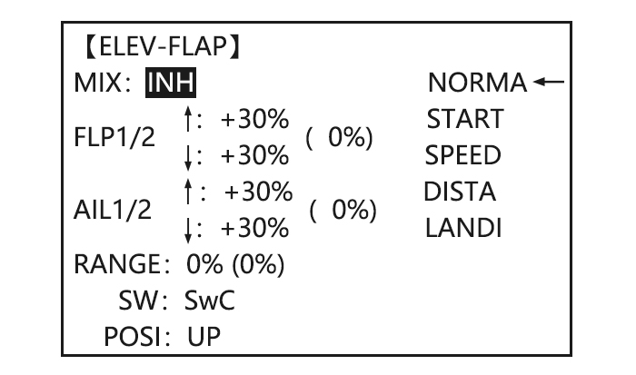
ACRO
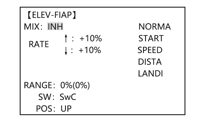
GLID
ELEV-FLAP mixing is the first pre-programmed mix we’ll cover. This mix makes the flaps drop or rise whenever ELEVATOR STICK is moved. It is most commonly used to make tighter pylon turns or squarer corners in maneuvers. In most cases, the flaps droop (are lowered) when up elevator is commanded.
Adjustability:
• Rate: -100% (full up flap) to +100% (full down flap), with a default of +50% (one-half of the flap range is achieved when the ELEVATOR STICK is pulled to provide full up elevator.)
• Switch: Fully assignable. Also LOGIC SW (Lsw1 to 3) may be assigned. IF you set it to NULL, the mix does not work. (ACRO)
•Range (GLID): The range that mixing does not work near neutral of an elevator stick can be set up. Hold the stick to the desired point (upper or lower side) , then press DIAL and hold one second to set the range.
• Condition (GLID): The separate ELEV-FLAP settings for each condition can be set.
|
Goals |
Steps |
Inputs |
|
|
Activate ELEV-FLAP mixing. Adjust flap travel to 0% flaps with negative elevator (push) and 45%flaps with positive elevator. |
Open ELEV-FLAP |
|
|
|
Activate the function |
|
||
|
Adjust the travels as needed. (Ex:0%, to45%) |
|
||
|
Close |
|
||
Dual Elevator Servos(AILEVATOR) (ACRO)
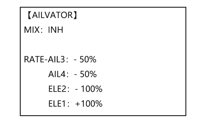
Many models use two elevator servos, plugged in separate receiver channels. (Flying wings without a separate aileron control use ELEVON.
V-shaped tail models use V-TAIL,
ADVANTAGE:
•Ability to adjust each servo’s center and end points for perfectly matched travel.
• Ease of assembly, not requiring torque rods for a single servo to drive 2 surfaces.
• Elevators acting also as ailerons for extreme stunt flying or more realistic jet flying (optional).
• Redundancy, for example in case of a servo failure or mid-air collision.
Adjustability:
• CH2 and CH8 only. (With programmable mixing, could utilize CH5 as the 2nd elevator servo.
THROTTLE-NEEDLE uses CH8 and cannot be active simultaneously).
• Direction of each servo’s travel may be reversed in REVERSE or the set percentages may be reversed here.
• Elevator travels independently adjustable (both directions and percent).
•Optional action as ailerons (defaults to 50% response). This response cannot be activated/ deactivated in flight. Setting AIL1 and 2 to 0 disables this feature.
Note: if you want this, but on/off with a switch, set AIL1 and 2 to 0 here, and use 2 mixes. AIL-to-AUX2 (link/trim off, assign a switch), get aileron action from the elevator servos when the assigned switch is on.
The AILEVATOR mixing function uses one servo on each of the two elevators, and combines the elevator function with the aileron function (unless aileron travel is set to 0). For aileron effect, the elevators are raised
and lowered opposite of one another in conjunction with the ailerons.’
Once AILEVATOR is activated, unless you zero out the aileron figures (see below), any time you move your ailerons or any programming moves your ailerons (i.e. RUDDER-AILERON mixing), the radio automatically commands both elevator servos to also operate as ailerons. To deactivate this action, simply set the 2 aileron travel settings to 0 in the AILEVATOR function. This way the elevators will work only as elevators.
|
Goals |
Steps |
Inputs |
|
Activate twin elevator servos. |
Open the AILEVATOR |
|
|
Activate the function. |
|
|
|
Optional: adjust up/down travel when operating as ailerons. (Ex:0) |
|
|
|
Optional: adjust total elevator travel of each servo. (Ex: right servo elevator travel to 98%,left to 96%) |
|
|
|
Close |
|
Snap Rolls(ACRO)
This function allows you to execute snap rolls by flipping a switch, providing the same input every time. It also removes the need to change dual rates on the 3 channels prior to performing a snap, as SNAP-ROLL always takes the servos to the same position, regardless of dual rates, inputs held during the snap, etc.
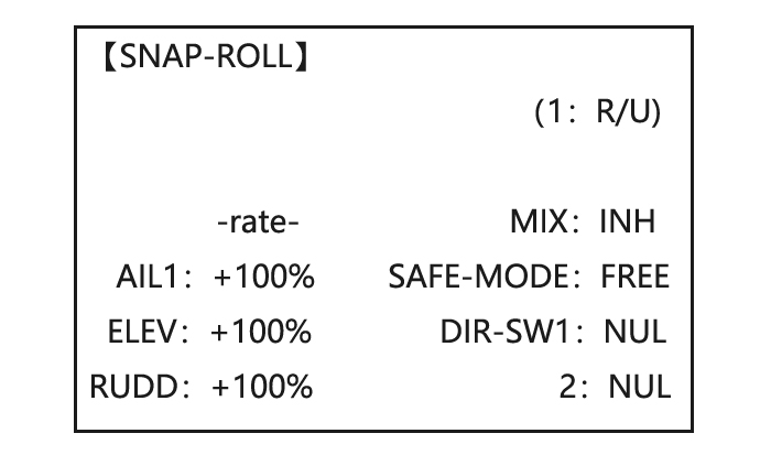
Note: Every MULTIROTOR snaps differently due to its C.G., control throws, moments, etc. Some models snap without aileron; others snap on elevator alone. Most models snap most precisely with a combination of all 3 surfaces. Additionally, rate of speed and acceleration when using the snap switch will affect how the model snaps. For information using gyros with airplanes for cleaner precision maneuvers, such as snaps and spins without over rotation.
Adjustability:
• Travel: Adjust the amount of elevator, aileron and rudder travel automatically applied.
• Range: -120 to +120 on all 3 channels. Default is 100% of range of all 3 channels.
• Directions: Up to 4 separate snaps is fully adjustable regarding travels and direction on each of the 3 channels.
Note: for simplicity, the radio refers to snaps that use “UP” or positive elevator as “U” or “UP” snaps. This is more commonly referred to as a positive or inside snap. “D” or “DOWN” snaps are more commonly referred to as negative or outside snaps.
• R/U = Right positive R/D = Right negative L/U = Left positive L/D = Left negative snap roll.
• Assignment of the 2 switches (DIR-SW1/2) to change snap directions is fully adjustable and optional. If you wish to have only one snap, leave the switches as NULL. (If assigned, SW1=up/down, SW2=left/right)
• Safety Switch (SAFE-MOD): a safety may be set up on your landing gear SWITCH, preventing accidental snap rolls while the landing gear is down. The safety switch is turned on and off with the landing gear SWITCH.
• ON: the safety mechanism is activated when the landing gear SWITCH is in the same position as at the time this feature is changed to ON. Snap rolls will not be commanded even if the snap roll SWITCH is turned on with the gear SWITCH in this position. When the landing gear SWITCH is moved to the opposite position, snap rolls may be commanded.
• OFF: Activate the safety mechanism in the opposite position from the ON function.
• FREE: The safety mechanism is completely turned off. Snaps can be commanded regardless of the gear SWITCH POSITION.
Note: The location of the safety switch always follows channel 5. If channel 5 is reassigned to switch C, for example, switch C is now the safety. If channel 5 is null or used as the second aileron servo, the safety function will not be available.
• Trainer Safety: SNAP-ROLL is automatically disabled when the trainer function is activated.
|
Goals |
Steps |
Inputs |
|
Activate SNAP-ROLL. Adjust elevator travel to 55%, rudder travel to 120% in the right/up snap. Activate SAFE-MODE so snaps can not be performed when gear is down. |
Open SNAP-ROLL. |
|
|
Activate the function |
|
|
|
Adjust the travel as needed. (Ex: elevator to 55%,rudder to 120%) |
|
|
|
Optional: Activate SAFE-MOD.(Ex: ON when Sw E or Sw G is down, meaning snap function is deactivate when that switch is in the down position) |
NOTE: MIX is OFF.
NOTE: MIX is ON. |
|
|
Optional: Assign switches up/down and left/right.(Ex: Change to the left/down snap and adjust rudder to 105%) |
Repeat steps above to set percentages. |
|
|
Close |
|
V-Tail(ACRO/GLID)
V-TAIL mixing is used with v-tail MULTIROTOR so that both elevator and rudder functions are combined for the two tail surfaces. Both elevator and rudder travel can be adjusted independently on each surface.
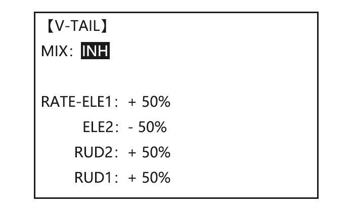
Note: NOTE: If V-TAIL is active, you cannot activate ELEVON or AILEVATOR functions. If one of these functions is active, an error message will be displayed and you must deactivate the last function prior to activating ELEVON.
Note: Be sure to move the elevator and rudder sticks regularly while checking the servo motions. If a large value of travel is specified, when the sticks are moved at the same time, the controls may bind or run out of travel. Decrease the travel until no binding occurs.
Adjustability:
• Requires use of CH2 and CH4.
• Independently adjustable travels allow for differences in servo travels.
• Rudder differential is not available. (To create rudder differential, set RUD1 and 2 to 0, then use two programmable mixes, RUD-ELE and RUD-RUD, setting different percents for up and down. These are your new rudder travels. Trim and link off, switch assignment null so you can’t accidentally turn off rudder.
ELEVON
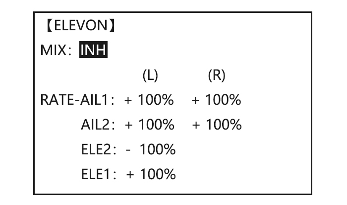
Adjustability:
• Requires use of CH1 and CH2.
• Independently adjustable aileron travel allows aileron differential.
• Independently adjustable elevator travel allows for differences in up vs. down travel.
• The separate ELEVON settings for each condition can be set. (GLID only)
Note: When changing the polarity of a rate, «change rate dir?» is displayed for a check. Please set up after pressing DIAL for 1 second and canceling an alarm display. (GLID only)
Note: Be sure to move the elevator and aileron sticks to full deflection during setup. If large travels are specified, when the AILERON and ELEVATOR STICKS are moved at the same time the controls may bind or run out of travel.
|
Goals |
Steps |
Inputs |
|
Activate ELEVON. |
Open ELEVON |
|
|
Activate the function. |
|
|
|
Optional: adjust up/down travel separately for the servos as ailerons.(Ex: down to 90%) |
|
|
|
Optional: adjust the elevator travel of each servo.(Ex: right servos elev. Travel to 98%, left to 105%.) |
|
|
|
Close |
|
Gyro Sense
The gyros have two operations modes: GY mode and STD mode.
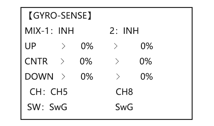
•STD mode: This mode performs general proportional control operation. For instance, it controls the gyro so that changes are countered when the attitude of the MULTIROTOR is changed by cross-wind, etc.
•GY mode: This mode performs both proportional and integrated control operation. The difference between Normal mode and GY mode operation is that where as the Normal mode only counters changes in attitude, the GY mode returns to the original controlled variable simultaneously with countering changes in attitude. For example, during knife edge flying, aileron and elevator meeting rudder is normally necessary, but in the GY mode, meeting rudder is performed automatically by the gyro.
Adjustability:
• Plug the gyro’s sensitivity adjustment to channel 5, 7, or 8 of the receiver. (Selectable)
• Full switch assignable (SWITCH A-H)
• Each rate setting may be set from 0 to NOR100% or AVC100% gain. NOR: GY mode gain. AVC: STD mode gain
• Larger percentages indicate more gain, or gyro responsiveness.
• MIX-1,2: Two surfaces’ sensitivity can be adjusted independently.
GYRO GAIN Adjustability:
• When the servo hunts, the gyro gain is too high. Lower the gain until the hunting stops.
• The gyro will display best performance at a gain just before hunting occurs. Perform adjusting by flying the MULTIROTOR repeatedly.
Precaution:
• When taking off and landing, always switch to the Normal mode. Taking off and landing in the GY mode is dangerous.
•We recommend that you use the rudder control gyro in the Normal mode. In the GY mode, rudder operation is necessary when turning because the weather vane effect is lost. Use the gyro in the Normal mode unless you are an expert in rudder operation.
• And we recommend that you also set to off (0%) mode for safety as follows.
|
Goals |
Steps |
Inputs |
|
Set up a GYA gyro setting (Ex:MIX-1) |
Open GYRO-SENSE |
|
|
Activate the function. |
|
|
|
Optional: change switches assignment. |
|
|
|
Adjust gyro rates as needed.(Ex: UP to NOR70%,CNTR to 0%[off], DOWN to AVC70% as starting points. |
|
|
|
Close |
|
THR-DELAY(ACRO)
The THR-DELAY function is used to slow the response of the throttle servo to simulate the slow response of a turbine engine. A 40% delay setting corresponds to about a one-second delay, while a 100% delay takes about eight seconds to respond. This function may also be used to create a “slowed servo” on a channel other than throttle. This is accomplished by plugging the desired servo (Ex: gear doors) into CH3 (THR), throttle into an auxiliary channel such as 8, and then using some creative mixes.
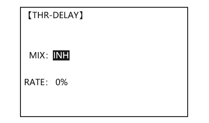
|
Goals |
Steps |
Inputs |
|
Activate THR-DELAY for a ducted-fan replica of a turbine-powered MULTIROTOR. |
Open THR-DELAY |
|
|
Activate the function. |
|
|
|
Adjust the RATE to match the desired servo speed.(Ex:40%) |
|
|
|
Close |
|
THR CURVE(ACRO)
This function adjusts the throttle operation curve for optimum the engine speed to throttle stick movement.
Note: If the throttle EXP function is activated, you can not use THR-CURVE function simultaneously.
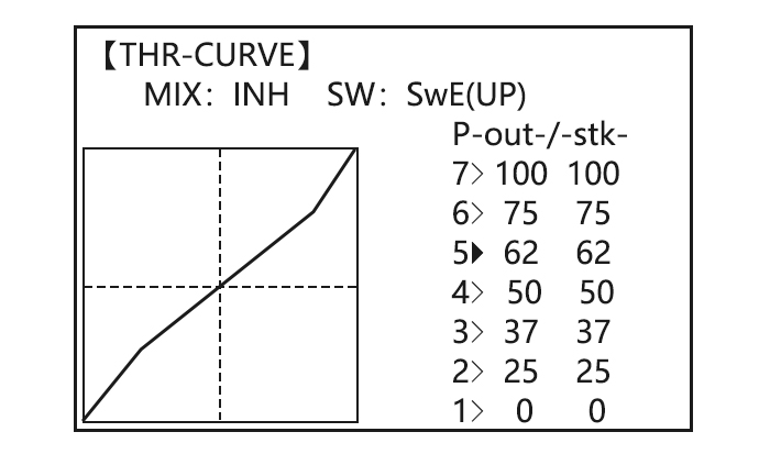
Adjustability:
• Separate curves for each switch position are available.
• Moving and deleting the curve point: The curve point (-STK-) can be moved to the left or right by turning the DIAL (up to 2% in front of the adjoining point) and deleted/returned by pressing the DIAL for one second alternately.
|
Goals |
Steps |
Inputs |
|
Base point: Adjust base point of throttle curve until engine idles reliably. |
Open THR-CURVE |
|
|
Activate the function. |
|
|
|
Adjust the 1st point |
|
|
|
Optional: assign the switch. |
|
|
|
Optional: Move the curve point.(Ex: point 3) |
|
|
|
Optional: delete the curve point. And return the curve point.(Ex: point 3) |
|
|
|
Adjust the next point. |
Repeat as needed. |
|
|
Close |
|
Throttle-Needle Mixing(ACRO/HELI)
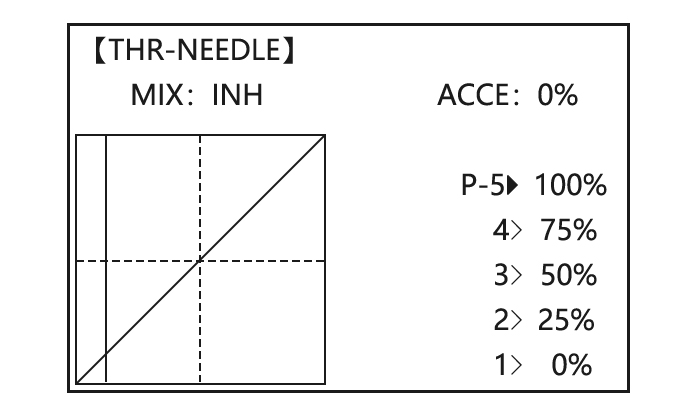
ACRO
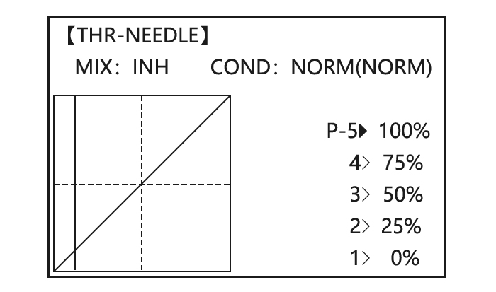
HELI
THROTTLE-NEEDLE is a pre-programmed mix that automatically moves an in-flight mixture servo (CH8) in response to the THROTTLE STICK inputs for perfect engine turning at all throttle settings. This function is particularly popular with contest pilots who fly in a large variety of locations, needing regular engine tuning adjustments, and requiring perfect engine response at all times and in all maneuvers. Also popular to minimize flooding at idle of inverted engine installations or installations with a high tank position. Not needed for fuel injection engines, which do this automatically.
Adjustability:
• Five-point curve allows adjustment of engine mixture at varied throttle settings.
• The in-flight mixture servo must connect to receiver CH8.
• In-flight mixture servo may also be used as a second servo for tuning a twin.
• Throttle cut feature also moves the in flight needle servo.
• The CH8 knob adjusts the high throttle mixture (may be deactivated. see AUX-CH).
• Because both use CH8, this function cannot be used simultaneously with AILEVATOR.
• An acceleration (ACCE) function (ACRO only) helps the engine compensate for sudden, large amounts of throttle input by making the mixture suddenly richer, then easing it back to the proper adjustment for that throttle setting. This function requires some adjustment to best fit your engine and your flying style. Adjust engine’s response until no hesitation occurs on rapid throttle input.
• Separate curves are available (HELI only) for normal, idle-ups 1 and 2 combined, and idle-up 3. Immediately below MIX the radio displays the curve you are editing; ex: >NORML; and then which condition is currently active by your switches ex: (ID1/2). Note that you can edit the mix for a different condition without being in that condition, to allow editing without having to shut off the helicopter’s engine every time. Be sure you are editing the proper curve by checking the name after the > and not the one in parentheses.
|
Goals |
Steps |
Inputs |
|
Activate THROTTLE- NEEDLE mixing. 1:40% 2:45% 3:65% 4:55% 5:40% |
Open THROTTLE-NEEDLE |
|
|
Activate the function. |
|
|
|
HELI only. Select the condition to edit. |
|
|
|
Adjust the travels as needed to match your engine by slowly moving the stick to each 5 points, then adjusting the percentage at that point until the engine is properly tuned. |
|
|
|
ACRO only . Optional: increase mixture when throttle is applied rapidly-ACCE.(see above for details) |
|
|
|
Heli only: set curves for another conditions. |
|
|
|
Close |
|
Glider Model Functions
Please note that nearly all of the BASIC menu functions are the same for airplane (ACRO setup), sailplane (GLID 1A+1F/ 2A+1F/ 2A+2F setups), and helicopter (HELI setups). The features that are identical refer back to the ACRO chapter. The glider BASIC menu includes MOTOR CUT and does not include IDLE-DOWN or THR-CUT.
→Note: in all cases where ACRO programming labels channel 3 as throttle, GLID programming labels channel 3 as ARB (airbrake), since airbrakes are normally operated on channel 3 in gliders. This includes STK-THR reading STK-ARB.
Basic Menu of Glid
This guideline is intended to help you get acquainted with the radio, to give you a jump start on using your new radio, and to give you some ideas and direction in how to do with this powerful system.
|
Goals |
Steps |
Inputs |
|
Prepare your airplane. |
Install all servos, switches, receiver per your model’s instructions. Turn on transmitter then receiver; adjust all linkages so surfaces are nearly centered. Mechanically adjust all linkages to get as close as possible to proper control throws and minimize binding prior to radio set up. Check servo direction and throws. Make notes now of what you will need to change during programming. |
|
|
Select the proper MODEL TYPE for your model. (Ex: GLID 1A+1F) [NOTE: This is one of several functions that require confirmation to make a change. Only critical changes such as a MODEL RESET require additional key strokes to accept the change.] |
In the BASIC menu, open PARAMETER submenu. |
Turn on the transmitter. |
|
Choose proper MODEL TYPE. Ex: GLID (1A+1F). |
|
|
|
Name the model |
In BASIC menu open the MODE SEL submenu. |
|
|
Input airplane name. |
|
|
|
REVERSE servos as needed for proper control operation. |
In the BASIC menu, open REVERSE. |
|
|
Choose desired servo and reverse its direction of travel. (Ex: reverse rudder servo.) |
|
|
|
Adjust travels as needed to match model’s recommended throws (usually listed as high rates). |
In BASIC menu choose END POINT. |
|
|
Adjust the servos’ end points. (Ex: flap servo). |
|
|
|
Choose D/R,EXP |
|
|
|
Set up dual/triple rates and exponential (D/R, EXP). (Note that in the middle of the left side of the screen is the name of the channel and the SWITCH position you are adjusting. Two or even three rates maybe set per channel by simply choosing the desired SWITCH and programming percentages with the SWITCH in each of its 2/3 position.) |
Choose the desired control, and set the first (Ex: high) rate throws and exponential. |
|
|
Set the second (Ex: low) rate throws and exponential. |
|
|
|
Optional: change dual rate SWITCH assignment. Ex: elevator to SWITCH G with 3 positions. |
|
|
|
Move flap control from the (VR (A)) dial to the left slider. [VR(D)](AUX-CH) . |
In the BASIC menu, open AUX-CH. |
|
|
Choose CH5. Change primary control to VR(D). Change other channels as needed. |
Repeat steps above to set other channels. |
|
|
Close |
|
Glid Type
TYPE: (GLID 1A+1F), GLID (2A+1F), GLID (2A+2F)
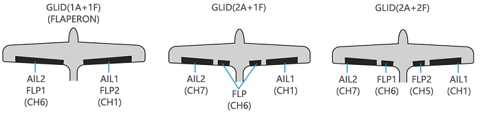
Before doing anything else to set up a glider or sailplane, first you must decide which MODEL TYPE best fits your MULTIROTOR.
• GLID(1A+1F): The GLID (1A+1F) MODEL TYPE is intended for sailplanes with one or two aileron servos (or none), and a single flap servo (or two connected with a y-connector). This TYPE is meant to be a very simplistic version to set up a basic glider without a lot of added features. Additional flight condition is available.
• GLID (2A+1F): The GLID (2A+1F) MODEL TYPE is intended for sailplanes with dual aileron servos and a single flap servo (or two connected with a y-connector). Additional flight conditions are available. These flight conditions contain different offset trims and aileron differentials to make the sailplane perform certain maneuvers more easily.
• GLID (2A+2F): The GLID (2A+2F) MODEL TYPE supports dual flap servos that can also act as ailerons, creating full-span ailerons and flap. Additional flight conditions are available. These flight conditions contain different offset trims and aileron differentials to make the sailplane perform certain maneuvers more easily.
Glid Advance Menu
MIXES:
• Linear Programmable mixes (PROG.MIX1-4): Fully assignable programmable mixed with a linear response.
• Curved Programmable mixes (PROG.MIX5-8): Fully assignable programmable mixed with a curved response.
• ELEV-FLAP pre-programmed mix creates elevator movement from the inboard flaps as well as elevators.
• BUTTERFLY: Often called crow, BUTTERFLY is the glider version of AIRBRAKE. (BUTTERFLY does not have the option to activate it solely from a switch, and its activation switch. It always provides progressively more BUTTERFLY as the CHANNEL 3 (THROTTLE) STICK is lowered, or raised if used THR-REV) See AIRBRAKE.
• CAMBER-MIX AILE-FLAP: This pre-programmed mix is used to create full span flap/aileron action on a glider with 4 wing servos. This changes the camber over the entire wing, which produces less drag than just dropping the flaps by themselves.
Note: When you have ELEV-FLAP mixing also, the trailing edge droops with the elevators, increasing pitch response.
• FLAPERON (GLID 1A+1F only): 2 aileron servos operate in opposite directions as ailerons and same direction as flaps.
• CAMBER FLAP: Provides camber movement or trimming of flaps. For sailplanes, this function is also used as wing camber. The amount depends on the model but usually a small amount (less then 10%) is preferred, since too much camber produces excess drag. Don’t use more than about 1/16″ travel up or down for glider camber. Some airfoils, such as the RG15, should be flown with NO reflex/camber. Be sure to consult your model’s manual for guidelines.
Note: even though you may make CAMBER FLAP active while using AILE-DIFF, it will not have any effect. The ONLY function that allows control of the ailerons as flaps in the AILE-DIFF configuration is airbrake/ butterfly
• ELEVON: for flying wings
• V-TAIL: For models with 2 servos operate together to create roll and pitch control.
• AILEVATOR: Not available in GLID model types.
AILE DIFF
FLAPERON(GLID 1A+1F)
FIND IN ACRO FUNCTION MENU
V-TAIL(Glid)
FIND IN ACRO FUNCTION MENU
OFFSET(GLID 2A+2F)
Additional flight conditions are available specifically for sailplanes.
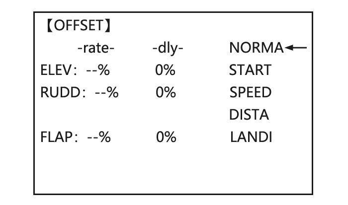
These additional flight conditions contain different offset trims to make the sailplane perform certain maneuvers more easily. Aileron differential functions may be set to provide separate rates per condition selected.
Prior to setting up OFFSET, you must active the conditions and assign the switches in the CONDITION/FUNCTION.
Unnecessary fuselage motion is generated when there are sudden changes in the servo position and variations in the operating time between channels can be suppressed by using the delay function.
Note: The same delay amount for elevator and rudder is recommended when using V-tail function.
The AT9 provides 5 additional setups along with the normal flight condition. (NORMAL,
START, SPEED, DISTANCE and LANDING) These offset trims have same setting abilities basically except the switch and dial assignment. For an example of trim settings, please see the following:
Adjustability:
• Separate adjustments for each aileron, elevator, rudder and flap servo, for each condition.
• SWITCH G (AT10) or E (AT10) is programmed for NORMAL, START, and SPEED trims. SWITCH C is programmed for DISTANCE and LANDING trims. These switch/position assignment is adjustable. (CONDITION/FUNCTION)
• TRIM item (Digital trim operation mode):
NORM: normal trim operation mode.
MIX: offset rate trim operation mode while mixing is on.
• Optional assignable knob (CAMBER MIX) to allow trimming in flight of the aileron and flap action of each flight condition.
• During OFFSET operation, the aileron and elevator travels are displayed on each trim display in the Startup screen.
|
Goals |
Steps |
Inputs |
|
Set up a START to gain maximum possible lift on launch. Each Aileron: 50%. Each Flap: 100%. Elevator: -5% to compensate. SWITCH (AT9=G, AT9=E.) Note: switch is assignable. (CONDITION) KNOB(null) Note: knob is assignable. (CAMBER MIX) |
Open OFFSET function |
|
|
Switch to the START condition. |
|
|
|
Set the rates. (Ex: AIL 50%, FLP 100%, ELEV -5 %.) |
Repeat for FLP and ELEV. |
|
|
Close |
|
Start Delay (GLID 1A+1F only)
START DELAY automatically switch the offset trims (OFFSET) from the START condition’s trims to the normal condition’s trims after proceeding the delay time (max.10sec.) which is set by the -DLY- item when activating the START condition. (It is convenient for hand launch glider.)
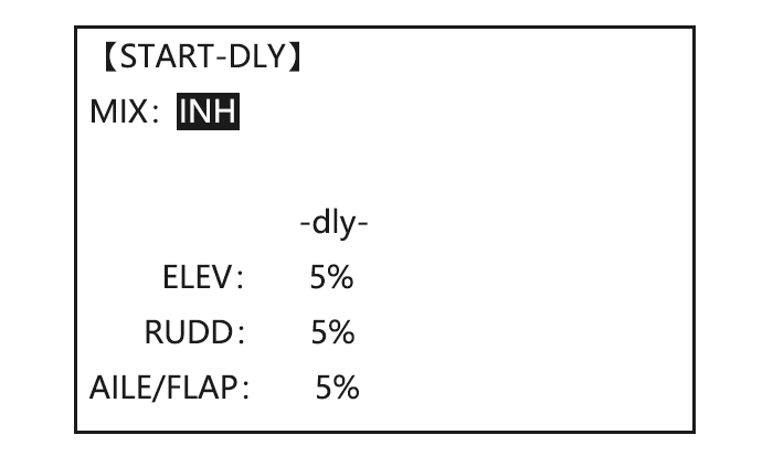
Note: The same delay amount for elevator and rudder is recommended when using V-tail function.
Adjustability:
• Delay time (-DLY-) range of 0 to 100%. The delay time is 10 second at 100%.
|
Goals |
Steps |
Inputs |
|
Ex: delay time=5 second. |
Open ADVANCE menu, then open START DELAY. |
|
|
Activate the function |
|
|
|
Set the delay time. |
Repeat as needed. |
|
|
Close |
|
Chamber-FLP
CAMBER FLAP assigns the primary flap control [defaults to VR (A)] to allow trimming in flight of the flap action. The up and down travel of each flap (camber flaps: FLP1/2) can be adjusted independently. Also the center position of flap servo can be offset.
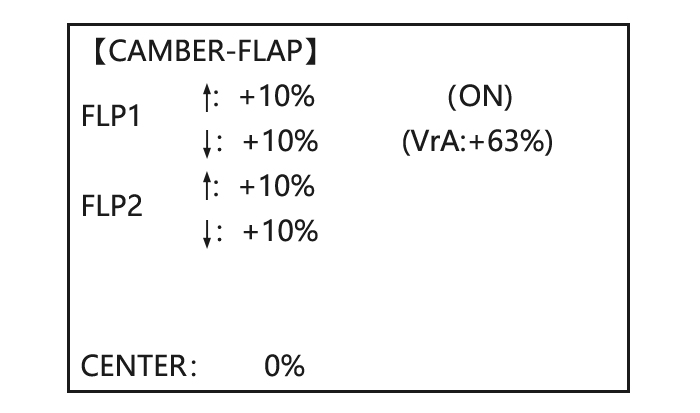
Note: If FLAP-TRIM is activated, you can not use CAMBER FLAP function simultaneously.
Adjustability
• Rate: -100% to +100%, with a default of +30%
• Center position (CENTER): The operation reference point of flap can be offset. -100% to +100%, with a default of 0%.
Note: When changing the polarity of a rate, «change rate dir?» is displayed for a check. Please set up after pressing DIAL for 1 second and canceling an alarm display.
|
Goals |
Steps |
Inputs |
|
Ex: Set the maximum travel of 35% of the total flap travel. |
Open the CAMBER FLAP function. |
|
|
Adjust the up/down trim amount separately.(Ex: adjust to 35%) |
Repeat. |
|
|
Or: adjust the center position of flap servo |
|
|
|
Close |
|
Camber Mixing
This function adjusts the mixing rate of camber operation which operates the wing camber (ailerons and flaps) in the negative and positive directions. The aileron, flap, and elevator rates can also be adjusted independently and attitude changes caused by camber operation can be corrected.
Also the operation reference point of camber control can be offset. (PRE)
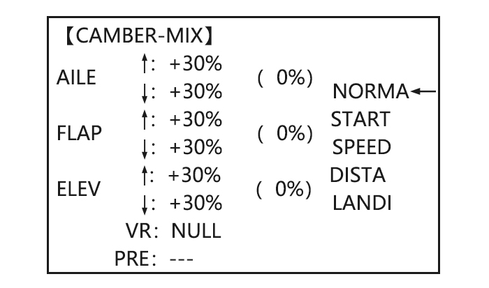
Note: Camber control is not assigned at initial.
Adjustability:
• Rate: -100% to +100%, with a default of +30%
• Reference point (PRE): The operation reference point of camber control can be offset. -100% to +100%, with a default of 0%.
|
Goals |
Steps |
Inputs |
|
Ex: set the mixing amount for aileron to 40%, camber control to VR (E), reference point to desired point. |
Open the CAMBER MIX function. |
|
|
Choose desired slider. |
|
|
|
Adjust the mixing amount for AILE. (Ex: adjust to 40%) |
|
|
|
Set the reference point. |
|
|
|
Close |
|
BUTTERFLY (crow) Mixing
BUTTERFLY simultaneously moves the flaps, twin ailerons and elevator, and is usually used to make steep descents or to limit increases in airspeed in dives. Separate two BUTTERFLY settings are available. (CRI1/CRI2)
Adjustability:
• Activation: Get proportional by moving the THROTTLE STICK.
• Switch: Mix SWITCH is selectable. A to H: SWITCH A to H. Also LOGIC SW (Lsw1 to 3) may be assigned. NULL: always on.
• Inversely proportional to THROTTLE STICK: provides a proportional increase in amount of airbrake action as THROTTLE STICK is lowered (when SWITCH A (assignable) is in down position). Includes selectable stick position where airbrake begins. If you would like to have the airbrake be directly proportional to throttle stick, you will need to reverse the THR-REV function.
Note: this changes the throttle stick direction for all models.
INSTRUCTIONS:
• Elevator settings: (Adjustable in the B.FLY-ELE)
B.FLY-ELE works linking with BUTTERFLY function. Elevator rate is adjustable in a 3 point curve.
Point 1: PRESET point. (Fixed)
Point 2: MID point. Position and rate are adjustable.
Point 3: END point. Position and rate are adjustable.
• Delayed reaction: You can suppress sudden changes in your model’s attitude when BUTTERFLY is activated by setting the delay (DELAY) item, to slow down the elevator response, allowing the flaps/ailerons/elevator to all reach their desired end point together. A setting of 100% slows the servo to take approximately one second to travel the prescribed distance.
• Channels controlled: Twin ailerons, flap and spoiler may be set independently in BUTTERFLY, including set to 0 to have no effect.
• Twin aileron servos: If AIL-DIFF function is inhibited, then AIL1 and AIL2 settings will have no effect. If AIL-DIFF is active, then CH1 and CH7 may be independently adjusted.
• Normally both ailerons are raised equally in BUTTERFLY, and the elevator motion is set to maintain trim when the ailerons rise. Different amounts may be set for each aileron to correct for torque reactions and other unique characteristics of the model.
Be sure you understand what dropping ailerons will do when in BUTTERFLY. Along with creating an enormous amount of drag (desirable for spot landings), this also creates «wash-in», a higher angle of attack where the ailerons are, and encourages tip stalling. If you are using this for aerobatic performance and not «sudden stops», consider raising the ailerons and dropping the flaps in stead as shown in the diagram above.
|
Goals |
Steps |
Inputs |
|
Activate BUTTERFLY. Adjust the aileron and flap travel to 75% Elevator setting is adjustable in the B.FLY-ELE. MIX switch is selectable |
Open the BUTTERFLY function |
|
|
Activate the function |
|
|
|
Adjust the travels as needed. |
|
|
|
Close |
|
AILE/RUDD MIX
You can select a pre-programmed mix which is used to mix the rudders with aileron operation or the ailerons with rudder operation.
Aileron-to-rudder mix (AILE RUDD): automatically creates a «coordinated turn».
Rudder -to-aileron mix (RUDD AILE): used to counteract undesirable roll (roll coupling) that happens with rudder input, especially in knife-edge.
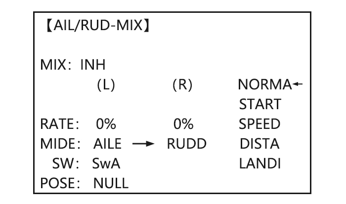
Adjustability:
• RATE range of -100 to +100. Negative setting would result in opposite rudder (aileron) action from aileron (rudder).
• SWITCH A-H fully assignable. Also LOGIC SW (Lsw1 to 3) may be assigned.
• POSITION fully assignable, including NULL (mix always on) and Up&Cntr and Cntr&Dn to activate the mix in 2 separate positions of the same SWITCH.
• Condition: The separate AILE RUDD setting for each flight condition can be set.
|
Goals |
Steps |
Inputs |
|
Ex:RUDD-AILE,25%,no switch, corrects roll coupling. |
Open AIL/RUD-MIX submenu. |
|
|
Select the mixing mode. |
|
|
|
Activate the function |
|
|
|
Set the rate (Ex:100% each way) |
|
|
|
Close |
|
ELEV-FLAP Mixing
AILE-FLAP(GLID 2A+2F only)
This pre-programmed mix is used to create full span aileron action on a glider
with 4wing servos. This increases the roll rate and decreases induced drag. For normal flying, a value of about 50% is often used. For slope racing or F3B models in speed runs, you may wish to use a larger value approaching 100%.
Adjustability:
• RATE range of -100 to +100. Negative setting would result in opposite aileron action from flaps.
• SWITCH A-H fully assignable. Also LOGIC SW (Lsw1 to 3) may be assigned.
• POSITION fully assignable, including NULL (mix always on) and Up&Cntr and Cntr&Dn to activate the mix in 2 separate positions of the same SWITCH.
• Condition: The separate AILE-FLAP settings for each flight condition can be set.
|
Goals |
Steps |
Inputs |
|
Turn on AILE-FLAP mixing. Set rate to 100% for maximum possible flap travel with ailerons .Assign to SWITCH C center. |
Open AILE-FLAP submenu. |
|
|
Activate the function |
|
|
|
Set the rate (Ex:100% each way) |
Repeat above to set FLP2 |
|
|
Assign the SWITCH and position. |
|
|
|
Close |
|
Spoiler Mix(GLID)
Moves the spoiler by flipping the assigned switch and is used to make steep decent. SPOILER MIX works linking with BUTTERFLY MIX.
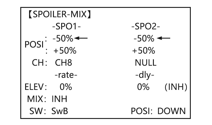
Adjustability:
• Position: -100% to +100%, with a default of -50% (off), +50% (on)
• Channel: Spoiler 1: ch8, or 3 (ch8 or 3*), Spoiler 2: NULL, or 3 (NULL or ch3*) *GLID (2A+2F) mode.
• Elevator setting: Rate: -100% to +100%, Delay: 0% to 100%
• SWITCH A-H fully assignable. Also LOGIC SW (Lsw1 to 3) may be assigned.
|
Goals |
Steps |
Inputs |
|
2-servo spoiler mode. Adjust the spoiler servo position to 60% |
Open the SPOILER MIX function and move to 2nd page. |
|
|
Activate the function. |
|
|
|
Assign the SPO2-CH.(Ex: CH3) |
|
|
|
Adjust the spoiler servo position. (Ex: SPO1/SPO2=+55% to +60%) |
|
|
|
Optional: Set the elevator rate.(Ex:10%) |
|
|
|
Optional: set the delay. (Ex:25%) |
|
|
|
Close |
|
FLAP-TRIM
Condition
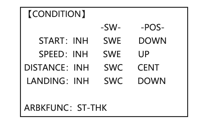
Channel 3’s function is selectable in the ARBK-FUNC item. (Throttle stick, switches, or knobs) By choosing except STK, channel 3’s function may be separated from Butterfly’s function, so channel 3 can be used for other functions.
Adjustability:
• Channel 3’s function:
STK: THROTTLE STICK
Sw-A to H: SWITCH A to H
Vr-A to Vr-E: KNOB A to E
Helicopter Model Functions
Please note that nearly all of the BASIC menu functions are the same for airplane (ACRO setup), sailplane (GLID setups), and helicopter (HELI) setups. The features that are identical refer back to the ACRO chapter.
Basic Menu(Helicopter)
This guideline is intended to help you set up a basic (H-1) heli, to get acquainted with the radio, to give you a jump start on using your new radio, and to give you some ideas and direction on how to do even more with this powerful system than you may have already considered.
Briefly, the typical helicopter’s controls are as follows:
• Aileron: Changes cyclic lateral (roll). Roll the helicopter. Tilt the swash plate to the left or right CH1.
• Elevator: Changes cyclic pitch. Change the helicopter’s angle of attack (nose up or nose down). Tilt the entire Swash plate fore and aft. CH2.
• Rudder: Change the angle of the tail rotor and yaw the helicopter left or right. CH4.
• Collective Pitch: Adjusts main rotor collective [angle of the paddles], changing the main blades’ pitch. Increased collective pitch (with throttle) causes the helicopter to rise. Moves in conjunction with throttle on the THROTTLE STICK. CH6.
• Throttle: Open/close carburetor. Move in conjunction with collective pitch on the THROTTLE STICK. CH3.
• REVO: mix that adds rudder in conjunction with pitch. This helps compensate for rotation of the helicopter caused by the increased engine torque. (Never use REVO. mixing with a heading0hold/AVCS gyro; the gyro already does this.)
|
Goals |
Steps |
Inputs |
|
|
Prepare your helicopter. |
Install all servos, switches, receiver per your model’s instructions. Set all trims, dials and sliders to neutral. Confirm all control linkages are 90 degrees (or per instructions ) from the servo horn to the ball link for proper geometry and that no slop is present. Mechanically adjust all linkages to get as close as possible to proper control throws and minimize binding prior to radio set up. |
||
|
Select proper mode type for your model. Ex: HELI H-1 |
In the BASIC menu, find PARAMETER. |
|
|
|
Go to MODEL TYPE. |
|
||
|
Select proper mode type. Ex: HELI H-1. Confirm the change. |
|
||
|
Then , NAME the model. |
In the BASIC menu, find PARAMETER. |
|
|
|
Go to MODEL SEL.-NAME |
|
||
|
Input name. |
|
||
|
Close the submenu when done. |
When proper character is display. |
||
|
Goals |
Steps |
Inputs |
|
Reverse servos as needed for proper control operation. Ex: Left Rudder Stick results in leading edges of tail rotor blades moving left. Reverse to operate properly. |
In BASIC menu, open Reverse. |
|
|
Choose desired servo and reverse its direction of travel. Ex: reverse rudder servo. |
|
|
|
Adjust travels as needed to match model’s recommended throws.(usually listed as high rates. |
In BASIC menu, choose END POINT. |
|
|
Adjust the servo’s end points. (Ex: elevator servo). |
|
|
|
Activate THR-CUT. |
Open THROTTLE-CUT function. |
|
|
Activate the function. Choose desired switch and position to activate. |
|
|
|
With THROTTLE STICK at idle, adjust the rate until the engine consistently shuts off, but throttle linkage is not binding.Close |
SwC |
|
|
Set up throttle curve for normal. (Usually changes will not need to be made prior to first flight.) |
Open the THR-CURV/NOR function. Adjust if needed. Close the function. |
|
|
Set up collective pitch curve for normal as base of -4, center of +5,end of +8 to +10 degrees of blade pitch for aerobatics.2 (If just learning to fly, ask your instructor.) |
Open the PIT-CURV/NOR function. Adjust each point to desired Curve.(Ex: first Point:8%) |
|
|
Set up REVO. Mixing for normal. (For heading-hold gyros, inhibit REVO.) |
Open the REVO./NOR function. Adjust to your desired starting point. (Ex: 10%.) Close the function. |
|
|
Confirm gyro direction. |
With radio on, move helicopter’s tail to the right by hand. The gyro should give right rudder input (leading edge of the tail rotor blades move left). If the gyro gives the opposite input, reverse direction on the gyro unit itself. |
|
Goals |
Steps |
Inputs |
|
Learn how to operate HOVERING PITCH and HOVERING THROTTLE |
Notice at half throttle, the VR(B) dial adjusts the throttle separately from the pitch. VR(A) adjusts the pitch separately from the throttle. |
|
|
Be sure to follow your model’s instructions for preflight checks, blade tracking, ect. Never assume a set of blades are properly balanced and will track without checking. |
||
|
Check receiver battery voltage! Always check voltage with a voltmeter prior to each and every engine start.(Never assume being plugged in all night means your radio gear is ready to fly).Insufficient charge, binding servo linkages ,and other problems can result in a dangerous crash with the possibility of injury to yourself, others and property. |
||
|
Confirm the swashplate is level at 0 travel. Adjust arms if needed. |
||
|
Apply full collective and check that the swashplate remained level and there is no binding. Repeat for full cyclic pitch and roll. If not, adjust as needed to correct in END POINT: |
||
|
Important note: prior to setting up throttle hold, idle-ups, offsets, etc, be sure to get your normal condition operating properly. |
1. Periodically move the throttle stick to full and back down to ensure proper servo settings.
2. It is critical that dials A and C be centered when the pitch and throttle curves are setup.
Basic Functions(Helicopter)
MODEL TYPE: This function of the PARAMETER submenu is used to select the type of model programming to be used. Before doing anything else to set up your model, first you must decide which MODEL TYPE best fits your MULTIROTOR.
HELICOPTER SWASHPLATE TYPES:
The AT9 radios support 8 basic swash plate setups, including «single servo» (H-1-most helicopters use this type) and 7 types of CCPM (cyclic and collective pitch mixing). A «single servo» swash plate uses one servo for each axis: aileron, elevator (cyclic pitch), and collective pitch. CCPM helicopters utilize a combination of servos working together to achieve the 3 axes of motion. There are 7 basic CCPM types, displayed below. CCPM has several advantages, the most obvious of which is far less mechanical complexity to properly move the swash plate of the helicopter. Additionally, several servos working in unison (ex: HR3, all 3 servos together create elevator movement) dramatically increases the torque available as well as the precision and centering.
Please note that some helicopters are type HR3 or HN3, except off by 180 degrees. If your model ‘s swash plate is off by 180 you will still use that swash plate type, but also use SWASH AFR to adjust the functions as needed until it operates properly. Additionally, different angles of CCPM may also be created utilizing the fully assignable programmable mixes.
Swash Plate Types
|
Goals |
Steps |
Inputs |
|
Change the model type and swashplate of model#3 from MULTIROTOR to 120 degree CCPM with 2 servos working in unison for collective pitch and aileron (Ex: HELI HR3) |
Confirm you are using the proper model memory(Ex:3) |
On home screen, check model name and # on top left. If it is not the correct model (Ex:3) see MODEL SEL. |
|
Open PARAMETER, go to MODEL SEL. |
|
|
|
Select proper MODEL TYPE (HELICOPTER) Confirm |
|
|
|
Change to desired SWASH TYPE (Ex: HR3) Confirm. |
|
|
|
Close |
|
Radio emits a repeating “beep” and shows progress on screen as the model type is being changed. Note that if the power switch is turned off prior to completion, the model type will not be changed.
Swash AFR(not in SWH1)
Except SWASH PLATE, function menu of helicopter is same as GLID/ ACRO. Please find the former instructions.
Swash plate function rate settings (SWASH AFR) reduce/increase/reverse the rate (travel) of the aileron, elevator (except H-2) and collective pitch functions, adjusting or reversing the motion of all servos involved in that function, only when using that function. Since these types utilize multiple servos together to create the controls, simply adjusting a servo’s REVERSE or END POINT would not properly correct the travel of any one control. Since H-1 uses one servo for each function, there is no need for AFR in H-1.
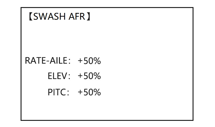
Since aileron always uses no more than 2 servos, check it first. Either both operate properly (no change needed), both operate backwards (reverse the whole function), or one servo operates backwards (reverse that servo alone). Next check elevator. Remember, the aileron servo(s) operate correctly, so if elevator does not, we should only have 2 choices left—the whole function needs to be reversed, or the servo(s) not shared with aileron need to be reversed. If aileron and elevator are not working properly, the only thing that could be wrong is the whole direction collective operates (reverse the whole function). In our example, HR3 is 180 degrees off from the swash plate of the Caliber. Therefore, it is very likely that several functions will not operate properly. The collective pitch operation is backwards; but reversing all three servos would also reverse the aileron and elevator operations. Changing the collective pitch rate, however, from +50% to -50%, will reverse the collective pitch without affecting the aileron action.
|
Checking For Proper Motion On An HR3 Swashplate |
|||
|
HR3 Swash Typ |
Proper Motion |
Wrong Motion |
How to Fix |
|
AILERON STICK. |
Swashplate tilts left. |
Reverse AIL setting in SWASH to -50%. |
|
|
Swashplate tilts right. |
Back of Swashplate moves up. |
Ch6 servo moves incorrectly; REVERSE. |
|
|
Back of Swashplate moves down. |
Ch1 servo moves incorrectly; REVERSE. |
||
|
ELEVATOR STICK. |
Front of swash plate moves down; |
Swashplate moves the opposite. |
Reverse ELE setting in SWASH. (ex: +50 to -50) |
|
back of swashplate moves up. |
Entire swashplate moves up. |
Ch2 servo moves incorrectly; REVERSE. |
|
|
RUDDER STICK. |
The leading edges of tail blades rotate left. |
Blades rotated right. |
REVERSE the rudder servo. |
|
THROTTLE STICK. |
Entire Swashplate lifts. |
Swashplate lowers. |
Reverse PIT setting in SWASH. |
|
Goals |
Steps |
Inputs |
|
Adjust the travel of the collective pitch from +50% to -23%, reversing the travel of all 3 servos and decreasing their travel in collective pitch only, on an HR3 SWASH TYPE. |
Open SWASH AFR function. |
|
|
Adjust PITC travel to -23% |
|
|
|
Close |
|
Advance Menu(Helicopter)
THR-CURVE and PIT-CURVE
These 7-point curves are utilized to best match the blade collective pitch to the engine RPM for consistent load on the engine. Curves are separately adjustable for normal, idle-up 1, idle-up 2, and idle-up 3. In addition, a separate collective pitch curve is available for throttle hold. Sample curves are displayed in the appropriate setup types (ex: normal flight condition) for clarity.
Suggested defaults:
• Normal: Collective pitch curve that results in points 1, 4 and 7 providing .4, +5, (+8 to +10)* degrees pitch. A throttle curve setting of 0, 25, 36, 50, 62.5, 75, 100%.
• Idle-ups 1 & 2: Idle-ups 1 and 2 are typically the same except for the gyro settings, with one being heading-hold/AVCS and the other being normal mode. The pitch curve will likely be similar to the normal curve above.
• Idle-up 3: Collective pitch curves that result in points 1, 4 and 7 providing (.8 to .10), 0, (+8 to +10) degrees. A throttle curve of 100, 75, 62.5, 50, 62.5, 75, 100 provide full throttle for inverted maneuvers.
• Throttle Hold pitch curve: Start with the normal pitch curve (for inverted autos, start from the idle-up 3 pitch curve), but increase the last point approximately 1-2°, if available, to ensure sufficient pitch at landing.
This default recommendation assumes you are doing forward flight. If you are just learning, please follow your instructor’s guidance. Some instructors like a +1 base point for training so that the helicopter comes down very slowly, even if your instincts pull the throttle/collective stick to the bottom in a hurry.
Adjustability:
• Normal condition curves are editable in the BASIC menu for convenience.
• All curves may be adjusted in the ADVANCE menu.
• Automatically selected with the proper condition.
• The idle-up curves are programmed to maintain constant RPM even when the collective pitch is reduced during flight (including inverted).
• To change which condition’s curve is being edited, cursor up to <COND> and change the curve named.
• For clarity, the name of the condition currently active (switched on in the radio) is shown in parentheses behind name of condition whose curve is being edited. (Example: see curve displays below. Note that the normal condition is active but the idle-up 1 condition’s curves are currently being edited.
• Moving and deleting the curve point: The curve point (-stk-) can be moved to the left or right by turning the DIAL (up to 2% in front of the adjoining point) and deleted/returned by pressing the DIAL for one second alternately.
• Idle-ups and throttle hold pitch curves may be edited even before the conditions have been made active. Activating their throttle curves activates these conditions.
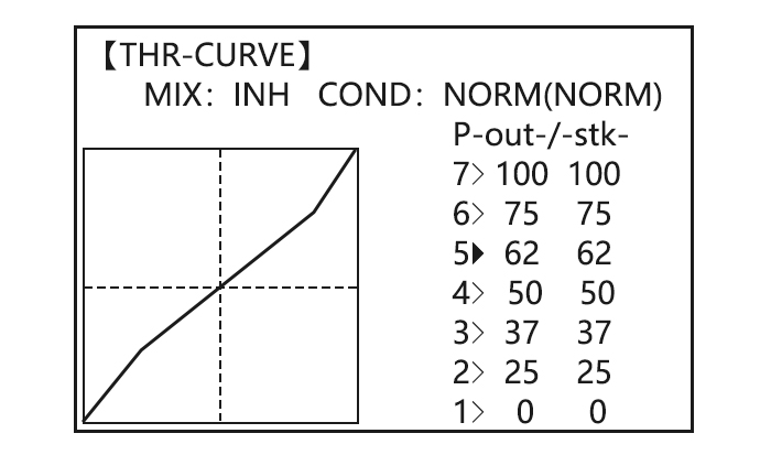
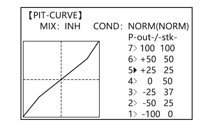
REVO Mix
This 5-point curve mix adds opposite rudder input to counteract the changes in torque when the speed and collective pitch of the blades is changed.
Adjustability:
• Three separate curves available: normal for hovering; idle-ups 1 and 2 combined; and idle-3.
• Normal condition curves are editable in the BASIC menu for convenience.
• All curves may be adjusted in the ADVANCE menu.
• Correct mix is automatically selected in-flight with each condition and automatically activated when the throttle setup for that condition is activated in the programming (i.e. THROTTLE HOLD or THR-CURVE.)
• To change which condition’s curve is being edited, cursor up above POINT5 and select. For clarity, the name of the condition currently active (switched on at the radio) is shown in parentheses behind the name of the condition whose curve is being edited.
Revo. Mixing rates are 5-point curves. For a clockwise-turning rotor, the rudder is mixed in the clockwise direction when collective pitch is increased; for counterclockwise-turning, the opposite. Change the operating direction setting by changing the signs of the numbers in the curve from plus (+) to minus (-) and vice versa.
Suggested defaults:
Clockwise rotation: -20, -10, 0, +10, +20% from low throttle to high.
Counterclockwise rotation: +20, +10, 0, -10, -20% from low throttle to high.
Adjust to the actual values that work best for your model.
Revo. Curves for idle-ups are often v-shaped to provide proper rudder input with negative pitch and increased throttle during inverted flight.(Rudder is needed to counter the reaction whenever there is increased torque. In inverted flight, throttle stick below half has increased throttle and negative pitch, therefore increasing torque and rotating the helicopter unless the revo. Mix is also increasing appropriately.)
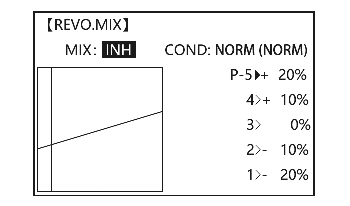
Note: The throttle and pitch curves for the normal condition is always on. They cannot be inhibited. The other four conditions are activated with their throttle curves or throttle hold.
• THR-CURV/NOR: Inputs the normal (NORM) throttle curve, which is usually not a linear response to THROTTLE STICK motion. Adjusting point 4 of the curve adjusts the engine’s RPM at the THROTTLE STICK midpoint, the desired position for hovering. The other 6 points are then adjusted to create the desired idle and maximum engine speed, and a smooth transition in-between.
• PIT-CURV/NOR: inputs the normal (NORM) collective pitch curve, the collective pitch curve for flight near hover. The normal collective pitch curve is adjusted to match the throttle curve, providing the best vertical performance at a constant engine speed, with a starting curve of 4 base, +5 neutral, and +8 to +10 degrees of blade pitch maximum. You can program the response over a 7-point curve for the best collective pitch angle relative to THROTTLE STICK movement.
• REVO./NORM: mixes collective pitch commands to the rudder (a PITCH-RUDDER mix) to suppress the torque generated by changes in the main rotor’s collective pitch angle, keeping the model from yawing when throttle is applied.
Note: There are three revo, mixes available: normal (NORM), idle-up 1/2 (IDL1/2), and idle-up 3 (IDL3). All 3 are adjustable in the ADVANCE menu. Never use revo mixing in conjunction with heading-hold/AVCS gyros. For details on revo, including default points for clockwise and counterclockwise rotating rotors.
|
Goals |
Steps |
Inputs |
|
Set up Normal Flight Condition Throttle/Collective Pitch Curves and Revo. Base point: Adjust base point of throttle curve until engine idles reliably on ground. Adjust base point of collective pitch curve to achieve -4 degrees of blade pitch. Apply throttle until the model sits ‘light’ on its skids. Adjust base point of REVO. until model does not rotate its nose at all. |
Open the THR-CURVE, Adjust the first point.(5%) |
|
|
Open the PIT-CURVE, Adjust the first point.(8%) |
|
|
|
Open the REVO.MIX Adjust the first point.(4%) |
|
|
|
Hover point: Adjust collective pitch curve to +5 degrees. Ease heli into a hover. Land/shut engine off. Adjust throttle curves and rudder trim. Repeat until model hovers smoothly at half throttle. Rapidly apply throttle from 1/4 to 1/2 stick. Adjust REVO. points 2 and 3 until the model does not rotate its nose up on throttle application. |
Adjust THR-CURV/NOR |
Repeat above as needed |
|
Adjust PIT-CURV/NOR |
Repeat above as needed |
|
|
Adjust REVO.MIX |
Repeat above as needed |
|
|
High point: Adjust collective pitch curve to +8 to +10 degrees. From hover, throttle up rapidly. If engine bogs, increase the throttle curve. If engine over-revs, increase the collective pitch curve at points 6 or 7. Apply full throttle while hovering, then descend back to hover. Adjust REVO. until the nose does not change heading. |
Adjust THR-CURV/NOR |
Repeat above as needed |
|
Adjust PIT-CURV/NOR |
Repeat above as needed |
|
|
Adjust REVO.MIX |
Repeat above as needed |
Gyro Sense
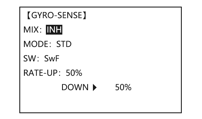
|
Goals |
Steps |
Inputs |
|
Set up heading- hold /AVCS gyro with heading-hold/AVCS setting in idle-ups 1 and 2 and normal mode setting in idle- up3 and normal. |
Open and activate the GYRO SENSE function. |
|
|
Activate the function. |
|
|
|
Optional: Change gyro types to Heading- hold (GY). |
|
|
|
Optional: Changes switch assignment. Ex: select Cond. |
|
|
|
Adjust gyro rates as needed. (Ex: NORM, IDL3 to NOR 50%. IDL1 and 2 to AVC 50% as starting points.) |
Repeat. |
|
|
Close |
|
Throttle Hold
This function holds the engine in the idling position and disengages it from the THROTTLE STICK when SWITCH AT9 is moved. It is commonly used to practice auto-rotation. Prior to setting up THR-HOLD, hook up the throttle linkage so that the carburetor is opened fully at high throttle, then use the digital trim to adjust the engine idle position. To have THR- HOLD maintain idle, move the THROTTLE STICK to the idle position, then move the hold SWITCH on and off and keep changing the offset value until the servo does not move. To lower the engine idle speed, or if you want to shut off, input a more negative number.
Adjustability:
• Idling position: Range of -50% to +50% centered about the throttle idle position to get the desired engine RPM.
• Switch assignment: Assigned to SWITCH E(AT10) or G (AT10) down. Adjustable in the CONDITION (THR-HOLD item), (2-position type switch only)
• Throttle curve: Since the throttle is moved to a single preset position, no curve is available for THR-HOLD.
• Collective pitch curve: Independent curve, typically adjusted to create a blade pitch range of -4% to +10% to +12%, is automatically activated with THRHOLD.
• Revo. mix: Since revo. mix adjusts for torque from the engine, no revo. mix is available for THR-HOLD.
• Priority: The throttle hold function has priority over idle-up. Be sure that the throttle hold and idle-up SWITCHES are in the desired positions before trying to start the engine. (We recommend starting your engine in throttle hold for safety reasons.)
• Gyro: Gyro programming includes an option to have a separate gyro setting for each condition, including THR-HOLD. This avoids the potential problem of the user being in the wrong gyro setting when going to THR-HOLD, resulting in an improper rudder offset and the model pirouetting.
|
Goals |
Steps |
Inputs |
|
Set up throttle hold. Determine desired throttle position by idling engine, turn on THR-HOLD, and adjust percentage as required to reach the desired running point. |
Open THR-HOLD function. |
|
|
Activate the function. |
|
|
|
Set desired engine position. |
|
|
|
Close |
|
Hovering Adjustments(HOV-THR and HOV-PIT)
Hovering throttle and hovering pitch are fine-turning adjustments for the throttle and collective pitch curves individually, affecting performance only around the center point and only in the normal condition. They allow in-flight tweaking of the curves for ideal setup.
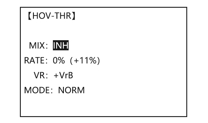
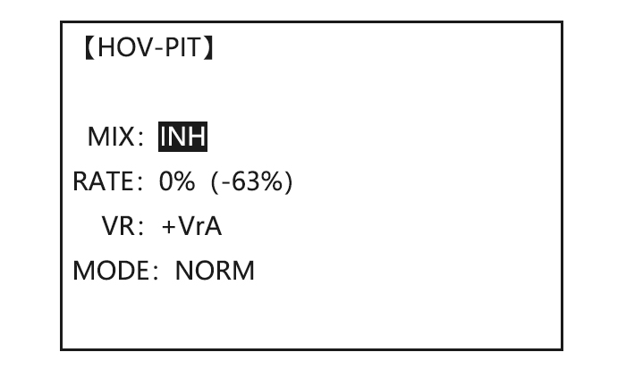
Adjustability:
• Rotor speed changes caused by temp., humidity, altitude or other changes in flying conditions are easily accommodated.
• Both adjustments may be inhibited if not desired.
• Both adjustments may also be set to NULL, temporarily turning off the knob but maintaining the last memorized setting.
• Adjustments may be memorized and then the knobs returned to center point to use that amount of adjustment, allows easy use of the trimming knobs for multiple models. (Note that when memorization is repeated with the knob offset from center, the trim value accumulates.)
• Adjustments are quickly reset to the initial value by turning the dial until the trim reads 0%, memorizing, then returning the knob to its center position.
• Note that all functions, including these, assume the model hovers at half stick.
•Available in normal (NORM) or normal/ idle-up1 (NORM/IDL1) condition only.
|
Goals |
Steps |
Inputs |
|
Fine-tune hovering with the hovering adjustments. Remember these affect only the hovering (normal) condition. Adjust throttle and collective pitch curves until model hovers nicely. In flight,adjust collective pitch and throttle curves near hover point independently with HOV-THR and HOV-PIT knobs. Store new settings after flight. |
Open the HOV-THR function |
|
|
Optional: change which knob adjust seach hovering curve. NULL locks in curve in last stored position. |
|
|
|
Close |
 |
|
|
Open the HOV-PIT function. |
|
|
|
Close |
|
High/Low Pitch(HI/LO-PIT)
This function may be used to adjust the curves high and low side individually for each flight condition (normal, idle-up 1, idle-up 2, idle-up 3, throttle hold).
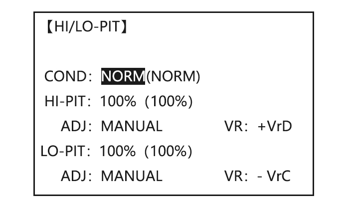
Adjustability:
• You may define high and low side rate trim knobs (the high side pitch trim control is defined as the right side lever at initial setting).
• The conditions are activated in the CONDITION SELECT function.
• Both adjustments may be set to MANUAL, temporarily turning off the knob.
• Adjustments may be memorized and then return the knobs to center point to use that amount of adjustment, allows easy use of the trimming knobs for multiple models.
|
Goals |
Steps |
Inputs |
|
Set up a high pitch curve in the idle-up 1condition. |
Open the HI/LO-PIT |
|
|
Select the idle-up 1 condition |
|
|
|
Set the rate (Ex:80%) |
|
|
|
Optional:Change which knob adjusts high pitch curve. |
|
|
|
Close |
|
Offset(Helicopter)
Optional separate trims in addition to those for the normal condition. This function is used to automatically change the trim of a helicopter, for example, when transitioned from hover to flying at high speed. A clockwise-rotation rotor helicopter tends to drift to the right at high speed, so an aileron offset may be applied to offset the helicopter to the left.
The necessary elevator offset varies with model geometry, so it must be determined by noting collective pitch changes at high speed. The rudder offset is affected by both revo. mixing and trim lever movement while in the offset function.
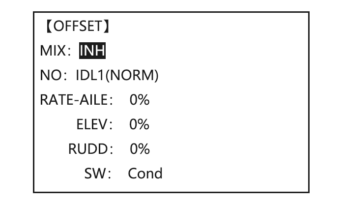
Adjustability:
• Complete switch assign ability, plus a CONDITION option that creates/ switches between individual trims for each of the idle-ups.
• When OFFSET is active (its switch is on), moving the TRIM LEVERS adjust the stored offset, not the trims in the normal condition.
•When OFFSET is inactive (its switch is off), the OFFSET and any trim adjustments to it have no effect (model obeys the trim settings of the currently-active flight condition.)
• When OFFSET is inhibited, trim adjustments made in any flight condition affect all flight conditions.
• Rapid jumps caused by large offsets can be slowed using the DELAY function.
• During OFFSET operation, the aileron, elevator, and rudder travels are displayed on each trim display in the Startup screen.
Note: Remember, offsets and revo mixes are not recommended when using heading-hold/AVCS gyros because they conflict with the automatic corrections to trim and torque that AVCS provides.
|
Goals |
Steps |
Inputs |
|
Set up separate trims for each of the three idle-up conditions. Adjust the idle-up 2 rudder trim to correct for torque at high speeds. |
Open the OFFSET function. |
|
|
Activate the function. |
|
|
|
Change switch setting to Cond. |
|
|
|
Select IDL2. |
|
|
|
Adjust trim settings as needed. (Ex:rudder to +8%.) |
|
|
|
Close menus and confirm slowed transitions. |
|
Delay(Helicopter)
The Delay function provides a smooth transition between the trim positions whenever OFFSET, REVO, MIXING, or THROTTLE HOLD functions are turned on and off.
Adjustability:
• Separate delay times are available for aileron, elevator, rudder, throttle, and pitch.
• With a 50% delay setting, the servo takes about a half-second to move to its new position, quite a long time.
• In general, delays of approximately 10-15% are sufficient.
|
Goals |
Steps |
Inputs |
|
Set up a delay on all channels to ease the transition from one flight condition to another so there are no ‘hard jumps’. |
Open the DELAY function. |
|
|
Adjust AILE response as needed. (Ex: aileron to +8%.) |
|
|
|
Repeat for other channels. |
|
|
|
Close menus and confirm slowed transitions. |
|
Governors(Helicopter)
The Governor mixing function is used to adjust the Governor speed settings (rS1, rS2, rS3) from the transmitter.
What is a governor? A governor is made up of a set of sensors which read the RPM of the helicopter’s head, and a control unit that automatically adjusts the throttle setting to maintain a constant head speed regardless of changes in pitch of blades, weather conditions, etc. Governors are extremely popular in competition helicopters due to the consistency provided.
How does it help in helicopter setup? The governor eliminates the need to spend large amounts of time setting up throttle curves, as it automatically adjusts the engine’s RPM to maintain the desired head speed.
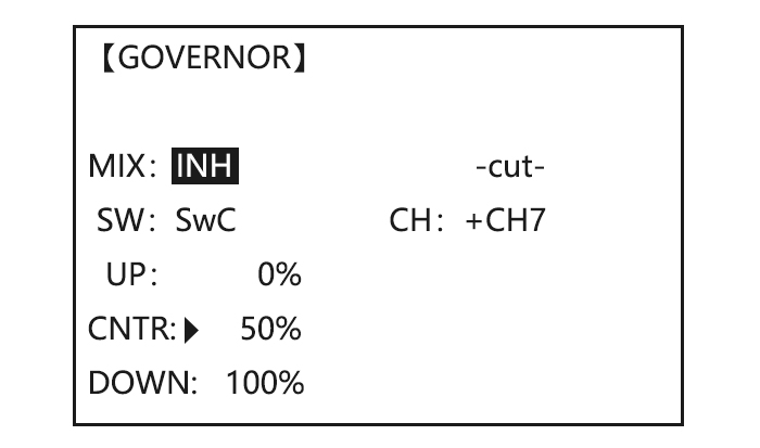
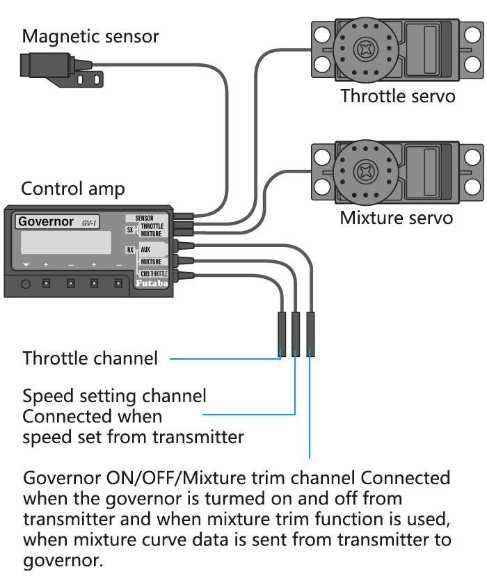
Adjustability:
• On/off may be separate from speed switching by plugging
governor on/off into CH8 and changing CUT-CH setting.
• If using separate on/off, switch assignment is totally adjustable.
Be careful not assign governor off to a condition switch if you
want the governor to function in that condition.
• Speed switching and governor ON/OFF may be together using one switch or ON/OFF switching may be performed using an independent switch/channel.
• When speed setting control uses CH7 and separate ON/OFF switch is not used, CH8 can be used for other functions.
• In-flight adjustment of the head speed (for easy adjustment during turning) may be created using an additional channel and a programmable mix.
The GV-1 controls throttle when it is active, so the throttle will not obey any Failsafe settings preset for throttle in the transmitter. Always set the Failsafe setting for the GV-1’s on/off channel to OFF. This way the governor is shut off and the throttle obeys the Failsafe throttle commands.
|
Goals |
Steps |
Inputs |
|
Set up a governor to use both channels into the receiver and switch between the governor settings automatically when changing conditions. Consider setting the battery Fail Safe settings and other helpful functions on the governor itself. |
Open and activate the GOVERNOR Function. |
|
|
Activate the function. |
|
|
|
Optional: change cut-off channel to channel 8 and assign switch and direction for on/off (channel 8). |
|
|
|
Optional: Changes switch assignment to select governor settings. Ex: select switch that selects the conditions. |
|
|
|
Adjust governor speed settings per switch position or condition as needed. (Ex: defaults are fine.) Allows head speed adjustment from transmitter. |
|
|
|
Close |
|
Throttle Mixing(Helicopter)
This function can be set for each flight condition, and is used to correct the tendency of the model to change altitude when the rotor is tilted by aileron, elevator, and rudder controls.
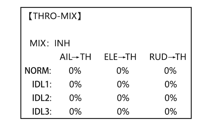
Adjustability:
• Mixing may be set from 0 to 100% each flight condition.
|
Goals |
Steps |
Inputs |
|
Correct the tendency of the model to change altitude. |
Open THRO- MIX function. |
|
|
Activate the function. |
|
|
|
Adjust the rate. Ex: IDL1 (AIL to TH) 10% |
|
|
|
Repeat as needed. |
||
|
Close |
|
Swash-Ring(Helicopter)
This function is to limit movement of swash plate to avoid damage to the SWASH ROB during operation aileron and ELEVATOR. It is affected in 3D flight. Movement of AILERON and ELEV is limited in the circle.
Adjustability:
• Initial: 100%
• adjusting range: 0-200%
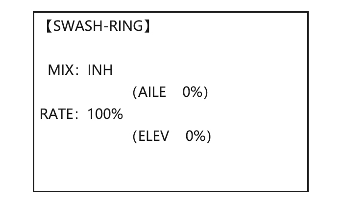
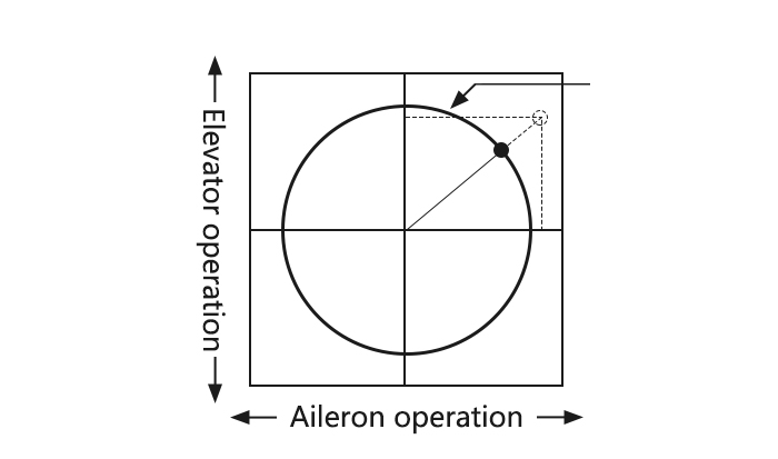
|
Goals |
Steps |
Inputs |
|
To prevent damaging the swash linkage by simultaneous operation of the ailerons and elevators, set the limit point where swash throw stops. *Adjust the rate at the maximum swash tilt by simultaneous operation of the ailerons and elevators. |
Open SWASH-RING function. |
|
|
Activate the function. |
|
|
|
Adjust the rate Ex: 90% |
|
|
|
Close |
|
Throttle Needle(Helicopter)
PROG MIX(Helicopter)
Condition(Helicopter)
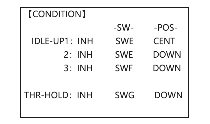
Revo., curves for idle-ups are often v-shaped to provide proper rudder input with negative pitch and increased throttle during inverted flight. (Rudder is needed to counter the reaction whenever there is increased torque. In inverted flight, throttle stick below half has increased throttle and negative pitch, therefore increasing torque and rotating the helicopter unless the revo. mix is also increasing appropriately.)
Additional flight conditions are available specifically for helicopters. These additional flight conditions contain different throttle curves, collective pitch curves, revo. mixing, and trims (except IDLE-3) to make the helicopter perform certain maneuvers more easily. Lastly, the gyro and dual rate functions may be set to provide separate rates per condition selected, including one for each idle-up.
Additional idle-ups may be used to maximize the helicopter’s flight characteristics in certain types of flight (i.e. fast forward motion, backward) or maneuvers (loops, rolls, stall turns), or even the same maneuver but changing from heading-hold/AVCS gyro mode to normal gyro mode. The AT9 provides 3 idle-ups to allow the modeler 3 additional setups along with the normal flight condition. (Note that IDL3 does not include governor settings.)
Adjustability:
• SWITCH G (AT9) or E (AT9) is programmed for normal (NORM), idle-up 1 (IDLE-UP1), and idle-up 2 (IDLE-UP2) curves, adjustable in CONDITION SELECT (IDLE-UP1/2, IDLE-UP3 items).
(IDLE-UP1/2 3-position type switch only, IDL3 2-position type switch only)
• Activated with the throttle curve for that condition in THR-CURVE.
• Curves are adjusted to maintain constant RPM even when the collective pitch is negative (inverted). Note that REVO mixing has one curve for idle-ups 1 and 2 and a second curve just for idle-up3.
•Gyro settings may be set separately for each idle-up.
• Governor settings may be set up to follow Normal/Idle1/Idle2, but do not offer a setting to adjust for each of the 5 conditions like gyro.
• Activating OFFSET makes the TRIM LEVERS adjust the trim separately in each of the idle-up conditions.
Multirotor Function
MULTIROTOR menu is the most differ between AT9S Pro and the other brand transmitter. The menu makes it easier to fly multi-copters. The basic function menu is same like ACRO, GLID and HELI, please find the detail in the former chapters.
Now let’s start the basic setting, take a quad copter for example:
|
Goals |
Steps |
Inputs |
|
Prepare your MULTIROTOR. |
Install all servos switched, receivers, etc. per your model’s instructions. Turn on the transmitter then receiver; adjust all linkages so surfaces are nearly centered. Mechanically adjust all linkages as close as possible to proper control throws. Check servo direction. Make notes now of what you will need to change during programming. |
|
|
Select proper MODEL TYPE. |
Open the BASIC menu find the MODEL TYPE. |
Turn on the transmitter, |
|
Go to TYPE |
|
|
|
Choose proper model type (Ex: MULTIROTOR). Confirm the change. |
|
|
|
Name the model. |
In BASIC menu, Open MODEL SEL. |
|
|
Input MULTIROTOR’s name. |
|
|
|
For proper control operation, reverse servos as needed. |
In the BASIC menu, open REVERSE. |
|
|
Choose desired servo and reverse its direction of travel.(Ex: reverse rudder servo) |
|
|
|
Adjust travels as needed to match model’s recommend throws(usually listed as high rates) |
From BASIC menu choose END POINT. |
|
|
Adjust the servo’s end points.(Ex: throttle servo) Close |
|
|
|
Back to choose D/R EXP. |
|
|
|
Set up dual/triple rates and exponential (D/P, EXP) (Note that in the middle of the left side of the screen is the name of the channel and the switch position you are adjusting. Two or even THREE rates may be set per channel by simply choosing the desired switch and programming percentages with the switch in each of its 2 or 3 positions. |
Choose the desired control and set the first (Ex: high) rate throws and exponential. |
|
|
set the first (Ex: low) rate throws and exponential. |
|
|
|
Optional: change dual rate switch assignment. |
|
|
|
Adjust AUX-CH and Knob. |
On BASIC menu, then open AUX-CH function. |
|
|
Choose CH5 to set ATTITUDE |
|
|
|
Assign the switch to control attitude. Ex: SW3 is SWC,SW2 is SWB |
|
|
|
Set the rate in each attitude. Ex: ATTI is 50%. |
|
|
|
Change CH6, use VR (D) to control change other channels as needed. |
|
|
|
Close |
|
Basic Menu(Multirotor)
The basic function menu is same like ACRO, GLID and HELI, please find the detail in the former chapters. Below is the special option:
Model Type(Multirotor)
Different from ACRO, GLID AND HELI, MODEL TYPE for MULTIROTOR has an additional function TRIM, which is controlled by the VR switch. Set the TRIM OFF to avoid a mis-operation damage to the model.
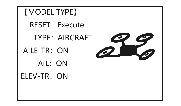
|
Goals |
Steps |
Inputs |
|
Select proper MODEL TYPE. (Ex: MULTIROTOR) |
Open BASIC menu, find MODEL TYPE. |
Turn on the transmitter, |
|
Go to MODEL TYPE |
|
|
|
Choose proper model type (Ex: MULTIROTOR). Confirm the change. |
|
|
|
Turn on the trim. |
|
|
|
Close |
|
AUX Channel Setting(Multirotor)
AUX channel for MULTIROTOR is channel 6 to 10, same like ACRO, GLID and HELI, to set auxiliary channel. CH5 is special for ATTITUDE, enter CH5 and press PUSH for ATTITUDE. Select 3-section and 2-section switch to get 6 different attitudes. By DIAL set 6 different rates according to the attitudes.
Advance Menu(Multirotor)
Attitude(Multirotor)
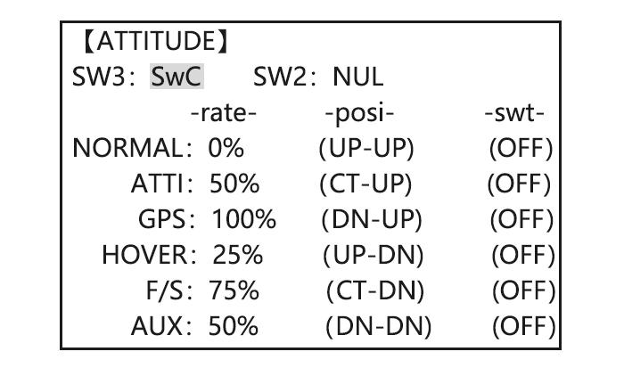
There are 6 different attitude modes for MULTIROTOR: NORMAL, ATTI, GPS, HOVER, F/S and AUX. Every mode will have a different rate to get a unique signal. NORMAL mode preset 0%, ATTI 50%, GPS 100%, HOVER 25%, F/S 75% and AUX 50%.
0% means a output signal 1ms, and 100% means 2ms. You can totally get 6 different modes by adjusting the related rates.
|
Goals |
Steps |
Inputs |
|
Set the ATTITUDE of MULTIROTOR. |
In ADVANCE menu find the ATTITUDE function. |
urn on the transmitter, |
|
Assign the switch to control attitude. Ex: SW3 is SWC,SW2 is SWB |
|
|
|
Set the rate in each attitude. |
|
|
|
Close |
|
Throttle Curve(Multirotor)
This function adjusts the throttle operation curve for optimum the engine speed to throttle stick movement.
Note: If the throttle EXP function is activated, you can not use THR-CURVE function simultaneously.
Adjustability:
• Separate curves for each switch position are available.
• Moving and deleting the curve point: The curve point (-STK-) can be moved to the left or right by turning the DIAL (up to 2% in front of the adjoining point) and deleted/returned by pressing the DIAL for one second alternately.
|
Goals |
Steps |
Inputs |
|
Base point: Adjust base point of throttle curve until engine idles reliably. |
Open THR-CURVE |
|
|
Activate the function. |
|
|
|
Adjust the 1st point |
|
|
|
Optional: assign the switch. |
|
|
|
Optional: Move the curve point.(Ex: point 3) |
|
|
|
Optional: delete the curve point. And return the curve point.(Ex: point 3) |
|
|
|
Adjust the next point. |
Repeat as needed. |
|
|
Close |
|
PROG. MIX(Multirotor)
AT9S Pro contains four separate linear programmable mixes. (Note that mixer #5-8’s mixing RATE are set with a 5-point curve. HELI has mixer #5-6’s mixing. See CURVE MIXES
There are a variety of reasons you might want to use these mixes. A few are listed here. All of the adjustable parameters are listed below, but don’t let them scare you. For your first few times experimenting with mixes, just turn on the default mixes, adjust them how you think they need to be, then use the servo screen to check and see if you were correct. As with all functions, a sample
setup follows, step by step, to assist you.
Sample reasons to use linear programmable mixes:
• To correct bad tendencies of the MULTIROTOR (such as rolling in response to rudder input).
• To operate 2 or more servos for a single axis (such as two rudder servos).
• To automatically correct for a particular action (such as lowering elevator when flaps are lowered).
• To operate a second channel in response to movement in a first channel (such as increasing the amount of smoke oil in response to more throttle application, but only when the smoke switch is active).
• To turn off response of a primary control in certain circumstances (such as simulating one engine flaming -out on a twin, or throttle-assisted rudder turns, also with a twin).
Adjustability:
• Defaults: The 4 programmable mixes default to the most frequently used mixes for simplicity. If you want to use one of these mixes, simply select that mix number so that the master and slave servos are already selected for you.
• PROG.MIX1 aileron-to-rudder for coordinated turns
• PROG.MIX2 elevator-to-flap for tighter loops (HELI mixes default to ELEV-to-pitch.)
• PROG.MIX3 flap-to-elevator to compensate pitching with flaps (HELI mixes default to pitch-to-ELEV)
• PROG.MIX4 throttle-to-rudder ground handling compensation
•Channels available to mix: All four mixes may use any combination of CH1-8. (CH9-10 is not proportional and cannot be mixed.) Offset and dials may also be set to the master channels.
•Master: the controlling channel, the channel whose movement is followed by the slave channel.
•Another channel: Most mixes follow a control channel. (Ex: rudder-to-ailerons, 25%, no switch, corrects roll coupling.)
|
MASTER |
SLAVE |
LINK |
TRIM |
SWITCH |
POSITION |
RATE |
OFFSET |
|
RUDD |
AILE |
ON |
OFF |
ANY |
NULL |
25% |
0 |
•Offset as master: To create an OFFSET mix, set the master as OFST. (Ex: Move FLAPERON as flaps 20% of their total throw when SWITCH C is in down position.)
|
MASTER |
SLAVE |
LINK |
TRIM |
SWITCH |
POSITION |
RATE |
OFFSET |
|
OFST |
FLAP |
ON |
N/A |
C |
DOWN |
20% |
0 |
• Dial as master: To directly effect one servo’s position by moving a dial, set the master as the desired dial. (Ex: create a second throttle trim on left slider.)
|
MASTER |
SLAVE |
LINK |
TRIM |
SWITCH |
POSITION |
RATE |
OFFSET |
|
VR(D) |
THRO |
OFF |
N/A |
ANY |
NULL |
5% |
0 |
•Slave: the controlled channel. The channel is moved automatically in response to the movement of the master channel. The second channel is in a mix’s name (i.e. aileron-to-rudder).
•Link: Link this programmable mix with other mixes.
Ex: PMIX FLAP-ELEVATOR mixing to correct for ballooning when flaps are lowered, but model has a V-tail. Without LINK, this mix only moves CH2 elevator when flap is commanded, resulting in a dangerous combination of yaw and roll. With LINK ON, mixing is applied to both CH2 and CH4.
|
MASTER |
SLAVE |
LINK |
TRIM |
SWITCH |
POSITION |
RATE |
OFFSET |
|
FLAP |
ELEV |
ON |
OFF |
ANY |
NULL |
5% |
0 |
•Trim: Master’s trim affects slave. Not displayed if master is not CH 1-4, because 5-9 have no trim. Ex: two rudder servos. With TRIM OFF, rudder trim would bind the two servos. TRIM ON resolves this.
• On/off choices:
• SWITCH: Any of the positions of any of the 8 switches may be used to activate a mix. Up&Cntr, Cntr&Dn options allow the mix to be ON in 2 of the 3 positions of a 3-position SWITCH.
• NULL: No SWITCH can turn this mix OFF. This mix is active at all times.
• LOGIC SW (Lsw1 to 3) may be assigned.
• STK-THR: Turn on/off by THROTTLE STICK movement. Trigger point/direction are selectable. Ex: OFST-to-(gear doors) mix to open gear doors at idle, which is only active if throttle is below half.
|
MASTER |
SLAVE |
LINK |
TRIM |
SWITCH |
POSITION |
RATE |
OFFSET |
|
OFST |
AUX2 |
OFF |
ON |
STK-THR |
Stick at 1/2.for 1 sec. |
100% |
0 |
• Rate: the percentage of the slave’s range it will move upon maximum input from the master channel. Ex: RUDDERAILERON mix, 50%. Ail range=1». When rudder is moved full right, ailerons move 1/2».
|
MASTER |
SLAVE |
LINK |
TRIM |
SWITCH |
POSITION |
RATE |
OFFSET |
|
RUDD |
AILE |
OFF |
OFF |
ANY |
NULL |
50% |
0 |
• Offset: Offsets the slave’s center is relative to the master. Ex: Smoke valve opens wider per throttle servo position when smoke SWITCH is ON. Smoke servo’s neutral is moved down from THROTTLE STICK center to the bottom.
|
MASTER |
SLAVE |
LINK |
TRIM |
SWITCH |
POSITION |
RATE |
OFFSET |
|
THRO |
AUX2 |
OFF |
OFF |
E |
DOWN |
100% |
100% |
|
Goals |
Steps |
Inputs |
|
Set up a FLAP-ELEV mix: No elevator movement when flaps move up(spoilers),5%elevator movement when flaps move down. Link should be ON if mode has twin elevator servos. Otherwise, Link remains OFF. |
Open an unused programmable mix.(Ex: use PROG.MIX3 since it is already set up for FLAP-ELEVATOR) |
|
|
Activate the function |
|
|
|
Choose master and slave channels. |
Already CH6 .Already CH2 |
|
|
Optional: set Master as OFST or VR(A-E) |
|
|
|
Set LINK and TRIM as needed. |
|
|
|
Assign SWITCH and position. |
|
|
|
Optional: set switch to STK-THR to activate mix with THROTTLE STICK. |
|
|
|
Optional: set switch position to NULL. Make mix active at all time. Not complete with STK-THR. |
|
|
|
Set rate. (Ex: Lo=0%,Hi=5%) |
|
|
|
Set OFF SET, if needed.(Ex:0) |
|
|
|
Close |
|
Other samples:
• RUD-ELEV (ACRO GLID) mix: Compensate for pitching up or down when rudder is applied.
• AIL-RUD mix (ACRO): Coordinate turns by applying rudder automatically with aileron input. All model types.
• ELEV-PIT (HELI) mix: Compensate for the loss of lift of tilting the model