-
Contents
-
Table of Contents
-
Troubleshooting
-
Bookmarks
Quick Links
Reference Manual
00809-0100-4004, Rev DC
May 2016
™
Rosemount
8800D Series Vortex
Flowmeter
Related Manuals for Emerson Rosemount 8800D Series
Summary of Contents for Emerson Rosemount 8800D Series
-
Page 1
Reference Manual 00809-0100-4004, Rev DC May 2016 ™ Rosemount 8800D Series Vortex Flowmeter… -
Page 3: Table Of Contents
Reference Manual Table of Contents 00809-0100-4004, Rev DC May 2016 Contents 1Section 1: Introduction How to use this manual……….1 Safety messages .
-
Page 4
Reference Manual Table of Contents 00809-0100-4004, Rev DC May 2016 Meter body installation tasks ……… . .28 3.5.1 Handling . -
Page 5
Reference Manual Table of Contents 00809-0100-4004, Rev DC May 2016 4.2.8 Device Information ……….64 4.2.9 Change HART Revisions . -
Page 6
Reference Manual Table of Contents 00809-0100-4004, Rev DC May 2016 B.2.3 Type n protection type in accordance with IEC 60079-15, EN60079-15 ……….141 European Directive Information . -
Page 7
Using non-nuclear qualified products in applications that require nuclear-qualified hardware or products may cause inaccurate readings. ™ For information on Rosemount nuclear-qualified products, contact your local Emerson Process Management Sales Representative. This product is intended to be used as a flowmeter for liquid, gas, or steam applications. -
Page 8
Reference Manual Title Page 00809-0100-4004, Rev DC May 2016 Title Page… -
Page 9: How To Use This Manual
This manual provides installation, configuration, operation, troubleshooting, and other ™ procedures for the use of the Rosemount 8800D Vortex Flowmeter. For model code ordering information, see the Rosemount 8800D Series Vortex Flowmeter Product Data Sheet. Section 2: Configuration contains information on entering and verifying basic configuration parameters.
-
Page 10
Reference Manual Introduction 00809-0100-4004, Rev DC May 2016 Introduction… -
Page 11: Process Variables
Reference Manual Configuration 00809-0100-4004, Rev DC May 2016 Section 2 Configuration Process variables …………page 3 Basic setup .
-
Page 12: Process Variable Units
Reference Manual Configuration 00809-0100-4004, Rev DC May 2016 2.1.4 Process Variable Units 2, 2, 2, 6 FastKeys Allows for the viewing and configuration of Process Variable Units such as Volume, Velocity, Mass Flow, Electronics Temperature, Process Density, and Corrected Volume units, including corrected volume Special Units configuration.
-
Page 13
Reference Manual Configuration 00809-0100-4004, Rev DC May 2016 Corrected Volumetric Flow Units 2,2,2,6,2 FastKeys Allows the user to select the corrected volumetric flow units from the available list. gallons per second imperial gallons per hour gallons per minute imperial gallons per day gallons per hour liters per second gallons per day… -
Page 14
Reference Manual Configuration 00809-0100-4004, Rev DC May 2016 Mass Flow Units 2, 2, 2, 6, 5 FastKeys Allows the user to select the mass flow units from the available list. (1 STon = 2000 lb; 1 MetTon = 1000 kg) grams per hour pounds per day grams per minute… -
Page 15
Reference Manual Configuration 00809-0100-4004, Rev DC May 2016 Special Units 2,2,2,7 (Volume) FastKeys 2,2,2,8 (Mass) 2,2,2,9 (Corrected Volume) Allows the user to create flow rate units that are not among the standard options. Configuration of a special unit involves entry of these values: base flow unit, base time unit, user defined unit and conversion number. -
Page 16
Reference Manual Configuration 00809-0100-4004, Rev DC May 2016 Special Flow Unit 2,2,2,7,5 (Volume) FastKeys 2,2,2,8,5 (Mass) 2,2,2,9,5 (Corrected Volume) A user created custom flow unit. The special unit is limited to four characters. The Field Communicator indicates the special unit with SPCL. The LCD display will display the actual four character user defined special unit. -
Page 17
Reference Manual Configuration 00809-0100-4004, Rev DC May 2016 Totalizer Config 2, 2, 4, 3, 3 FastKeys Used to configure the flow parameter (volume, mass, velocity, or corrected volume flow) that will be totaled. Note The totalizer value is saved in the non-volatile memory of the electronics every three seconds. -
Page 18
Reference Manual Configuration 00809-0100-4004, Rev DC May 2016 Calculated Process Density 3, 2, 1 FastKeys Allows the user to view the calculated process density value when the transmitter is configured for temperature compensated steam or temperature compensated liquid applications. Process Density Units 2, 2, 2, 6, 7 (without MTA) FastKeys 2, 2, 2, 6, 8 (with MTA) -
Page 19: Basic Setup
Reference Manual Configuration 00809-0100-4004, Rev DC May 2016 Basic setup 2, 1, 1, 1 FastKeys The Rosemount 8800D must be configured for certain basic variables in order to be operational. In most cases, all of these variables are pre-configured at the factory. Configuration may be required if your Rosemount 8800D is not configured or if the configuration variables need revision.
-
Page 20: Reference K-Factor
2, 2, 1, 2, 1 FastKeys A factory calibration number relating the flow through the meter to the shedding frequency measured by the electronics. Every 8800 meter manufactured by Emerson is run through a water calibration to determine this value. Configuration…
-
Page 21: Flange Type
Reference Manual Configuration 00809-0100-4004, Rev DC May 2016 2.2.5 Flange Type 2, 2, 1, 4, 2 FastKeys Enables the user to specify the type of flange on the flowmeter for later reference. This variable is preset at the factory but can be changed if necessary. Wafer PN25 …
-
Page 22: Variable Mapping
Reference Manual Configuration 00809-0100-4004, Rev DC May 2016 Pipe size Schedule 10 Schedule 40 Schedule 80 inches (mm) inches (mm) inches (mm) inches (mm) 6 (150) 6.357 (161.5) 6.065 (154.1) 5.761 (146.3) 8 (200) 8.329 (211.6) 7.981 (202.7) 7.625 (193.7) 10 (250) 10.420 (264.67) 10.020 (254.51)
-
Page 23: Process Variable Units
Reference Manual Configuration 00809-0100-4004, Rev DC May 2016 Fourth Variable 2, 2, 2, 4 FastKeys Selections for the Fourth Variable are identical to those of the Secondary Variable. 2.2.8 Process Variable Units 2, 2, 2, 6 FastKeys This selection allows the user to set the units of measure for all available process variables. 2.2.9 Analog Output 3, 4, 3, 1…
-
Page 24: Damping
Reference Manual Configuration 00809-0100-4004, Rev DC May 2016 2.2.10 Damping 2, 1, 4, 1 FastKeys Damping changes the response time of the flowmeter to smooth variations in output readings caused by rapid changes in input. Damping is applied to the Analog Output, Primary Variable, Percent of Range, and Vortex Frequency.
-
Page 25
Reference Manual Configuration 00809-0100-4004, Rev DC May 2016 Table 2-2. Fast Keys for Rosemount 8800D HART 7 Device Revision 2 (DD Revision 1)/ HART 5 Device Revision 3 (DD Revision 1) Function Fast Key Function Fast Key Analog Output 3, 4, 3, 1 Polling Address 2, 2, –… -
Page 26
Reference Manual Configuration 00809-0100-4004, Rev DC May 2016 Figure 2-1. Overview Menu Map Overview Device Status Universal Refresh Alerts Comm Status Long Tag Field Device Clear Config Changed Flag Primary Variable Model Software Active Alerts Primary Variable Value Serial Number Hardware Status Date… -
Page 27
Reference Manual Configuration 00809-0100-4004, Rev DC May 2016 Figure 2-2. Configure Menu Map Configuration… -
Page 28
Reference Manual Configuration 00809-0100-4004, Rev DC May 2016 Figure 2-3. Service Tools Menu Map Configuration… -
Page 29: Safety Messages
Reference Manual Installation 00809-0100-4004, Rev DC May 2016 Section 3 Installation Safety messages …………page 21 Commissioning .
-
Page 30
Reference Manual Installation 00809-0100-4004, Rev DC May 2016 Figure 3-1. Installation Flowchart Bench START HERE Commissioning? FIELD INSTALL Review CONFIGURE Configuration Mount Flowmeter Configuration Process Config Transmitter Mode Process Fluid Fixed Process Temp. Mount Base Density Conduit Go to (Std. -
Page 31: Commissioning
Reference Manual Installation 00809-0100-4004, Rev DC May 2016 Commissioning Commission the Rosemount 8800D before putting it into operation. This ensures proper configuration and operation of the meter. It also enables you to check hardware settings, test the flowmeter electronics, verify flowmeter configuration data, and check output variables.
-
Page 32
Reference Manual Installation 00809-0100-4004, Rev DC May 2016 Horizontal installation For horizontal installation, the preferred orientation is to have the electronics installed to the side of the pipe. In liquid applications, this ensures any entrained air or solids do not strike the shedder bar and disrupt the shedding frequency. -
Page 33: Wetted Material Selection
Ensure that the process fluid is compatible with the meter body wetted materials when specifying the Rosemount 8800D. Corrosion will shorten the life of the meter body. Consult recognized sources of corrosion data or contact your Emerson Flow Sales Representative for more information.
-
Page 34: Environmental Considerations
Reference Manual Installation 00809-0100-4004, Rev DC May 2016 3.2.4 Environmental considerations Avoid excessive heat and vibration to ensure maximum flowmeter life. Typical problem areas include high-vibration lines with integrally mounted electronics, warm-climate installations in direct sunlight, and outdoor installations in cold climates. Although the signal conditioning functions reduce susceptibility to extraneous noise, some environments are more suitable than others.
-
Page 35: Failure Mode Vs. Saturation Output Values
Reference Manual Installation 00809-0100-4004, Rev DC May 2016 Figure 3-5. Alarm and Security Jumpers Alarm As part of normal operations, the Rosemount 8800D continuously runs a self-diagnostic routine. If the routine detects an internal failure in the electronics, flowmeter output is driven to a low or high alarm level, depending on the position of the failure mode jumper.
-
Page 36: Lcd Indicator Option
Reference Manual Installation 00809-0100-4004, Rev DC May 2016 Table 3-1. Analog Output: Standard alarm values vs. Saturation Values Level 4—20 mA saturation value 4—20 mA alarm value 3.9 mA < 3.75 mA ≥ 21.75 mA High 20.8 mA Table 3-2. Analog Output: NAMUR-Compliant Alarm Values vs. Saturation Values Level 4—20 mA saturation value 4—20 mA alarm value…
-
Page 37: Flow Direction
Reference Manual Installation 00809-0100-4004, Rev DC May 2016 Figure 3-7. Lifting Supports 3.5.2 Flow direction Mount the meter body so the FORWARD end of the flow arrow, shown on the meter body, points in the direction of the flow in the pipe. 3.5.3 Gaskets The Rosemount 8800D requires gaskets supplied by the user.
-
Page 38
Reference Manual Installation 00809-0100-4004, Rev DC May 2016 Table 3-3. Minimum Recommended Stud Bolt Lengths for Wafer Installation with ASME B16.5 (ANSI) Flanges Minimum recommended stud bolt lengths (in Inches) for each flange rating Line size Class 150 Class 300 Class 600 ½-inch 6.00… -
Page 39: Wafer-Style Flowmeter Alignment And Mounting
Reference Manual Installation 00809-0100-4004, Rev DC May 2016 3.5.5 Wafer-style flowmeter alignment and mounting Center the wafer-style meter body inside diameter with respect to the inside diameter of the adjoining upstream and downstream piping. This will ensure the flowmeter achieves its specified accuracy.
-
Page 40
Reference Manual Installation 00809-0100-4004, Rev DC May 2016 Figure 3-8. Wafer-Style Flowmeter Installation with Alignment Rings FLOW A. Installation studs and nuts (supplied by customer) B. Alignment rings C. Spacer (for Rosemount 8800D to maintain Rosemount 8800A dimensions) D. Gaskets (supplied by customer) Figure 3-9. -
Page 41: Flanged-Style Flowmeter Mounting
Reference Manual Installation 00809-0100-4004, Rev DC May 2016 3.5.6 Flanged-style flowmeter mounting Physical mounting of a flanged-style flowmeter is similar to installing a typical section of pipe. Conventional tools, equipment, and accessories (such as bolts and gaskets) are required. Tighten the nuts following the sequence shown in Figure 3-11.
-
Page 42
Reference Manual Installation 00809-0100-4004, Rev DC May 2016 Figure 3-10. RED Area for Both Integral and Remote Electronics Connection Types A. Do not insulate within the RED area for both integral and remote electronics connection types. B. 1 in. (25 mm) minimum Installation… -
Page 43: Flowmeter Grounding
Reference Manual Installation 00809-0100-4004, Rev DC May 2016 Figure 3-11. Flange Bolt Torquing Sequence 3.5.7 Flowmeter grounding Grounding is not required in typical vortex applications; however, a proper ground will eliminate possible noise pickup by the electronics. Grounding straps may be used to ensure that the meter is grounded to the process piping.
-
Page 44: High-Temperature Installations
Reference Manual Installation 00809-0100-4004, Rev DC May 2016 3.6.1 High-temperature installations Install the meter body so the electronics are positioned to the side of or below the pipe as shown in Figure 3-2 on page 24. Insulation may be required around the pipe to maintain an ambient transmitter temperature below 185 °F (85 °C) or the more restrictive temperature ratings marked on hazardous locations tags.
-
Page 45: Cable Gland
Reference Manual Installation 00809-0100-4004, Rev DC May 2016 3.6.4 Cable gland If you are using cable glands instead of conduit, follow the cable gland manufacturer’s instructions for preparation and make the connections in a conventional manner in accordance with local or plant electrical codes. Be sure to properly seal unused ports to prevent moisture or other contamination from entering the terminal block compartment of the electronics housing.
-
Page 46
Reference Manual Installation 00809-0100-4004, Rev DC May 2016 Note A minimum loop resistance of 250 ohms is required to exchange information with a HART-based communicator. With 250 ohms of loop resistance, the flowmeter will require a minimum power supply voltage (V ) of 16.8 volts to output 24 mA. -
Page 47
Reference Manual Installation 00809-0100-4004, Rev DC May 2016 Note Twisted pairs are required to minimize noise pickup in the 4–20 mA signal and digital communication signal. For high EMI/RFI environments, shielded signal wire is required and recommended in all other installations. To ensure communication, wiring should be 24 AWG or larger and not exceed 5,000 ft (1500 m). -
Page 48
Reference Manual Installation 00809-0100-4004, Rev DC May 2016 Note When using pulse output, be sure to follow these precautions: Shielded twisted pair is required when the pulse output and 4–20 mA output are run in the same conduit or cable trays. Shielded wire will also reduce false triggering caused by noise pickup. -
Page 49: Remote Electronics
Reference Manual Installation 00809-0100-4004, Rev DC May 2016 Figure 3-16. 4-20 mA Wiring ≥ 250 Ω A. Power supply Figure 3-17. 4–20 mA and Pulse Wiring with Electronic Totalizer/Counter >250 Ω − 100 Ω < R < 100 kΩ − −…
-
Page 50
Reference Manual Installation 00809-0100-4004, Rev DC May 2016 Cable connections Refer to Figure 3-18 and the following instructions to connect the loose end of the coaxial cable to the electronics housing. (See “Remote electronics procedure” on page 88 if con- necting/disconnecting the meter adapter to the meter body.) Figure 3-18. -
Page 51: Calibration
Reference Manual Installation 00809-0100-4004, Rev DC May 2016 Slide the housing adapter over the coaxial cable. Remove one of the four housing base screws. Attach the coaxial cable ground wire to the housing via the housing base ground screw. Attach and securely tighten the coaxial cable nut to the connection on the electronics housing.
-
Page 52
Reference Manual Installation 00809-0100-4004, Rev DC May 2016 Figure 3-19. Rosemount 8800D with Optional Indicator A. Electronics board The indicator features an eight-character (and five alphanumeric) liquid crystal display that gives a direct reading of the digital signal from the microprocessor. During normal operation, the display can be configured to alternate between the following readings: Primary variable in engineering units … -
Page 53: Installing The Indicator
Reference Manual Installation 00809-0100-4004, Rev DC May 2016 Figure 3-20. Optional Liquid Crystal Display A HART-based communicator can be used to change the engineering units of the parameters displayed on the indicator. (See Section 4: Operation for more information). 3.7.1 Installing the indicator For flowmeters ordered with the LCD indicator, the indicator is shipped installed.
-
Page 54: Transient Protection
Reference Manual Installation 00809-0100-4004, Rev DC May 2016 Insert the mounting screws into the LCD indicator. Remove the two jumpers on the circuit board that coincide with the Alarm and the Security settings. Insert the connector into the Alarm/Security junction. Gently slide the LCD indicator onto the connector and tighten the screws into place.
-
Page 55: Installing The Transient Protector
Reference Manual Installation 00809-0100-4004, Rev DC May 2016 3.8.1 Installing the transient protector For flowmeters ordered with the transient protector option (T1), the protector is shipped installed. When purchased separately from the Rosemount 8800D, you must install the protector on a Rosemount 8800D Flowmeter using a small instrument screwdriver, a pliers, and the transient protection kit.
-
Page 56
Reference Manual Installation 00809-0100-4004, Rev DC May 2016 Installation… -
Page 57: Diagnostics/Service
Reference Manual Operation 00809-0100-4004, Rev DC May 2016 Section 4 Operation Diagnostics/service …………page 49 Advanced functionality .
-
Page 58: Loop Test
Reference Manual Operation 00809-0100-4004, Rev DC May 2016 Self Test 3, 4, 4, 1, 1 FastKeys Although the Rosemount 8800D performs continuous self-diagnostics, you can initiate an immediate diagnostic to check for possible electronics failure. Self test checks proper communications with the transmitter and provides diagnostic capabilities for transmitter problems.
-
Page 59: Analog Trim
Reference Manual Operation 00809-0100-4004, Rev DC May 2016 Simulate Flow 3, 5, 1, 2, 1 FastKeys Allows flow simulation using either an internal or external sensor input signal. Internal Flow Simulation 3, 5, 1, 2, 1, 2 FastKeys Disconnects the sensor signal from the electronics, and allows for configuration of the internal flow simulation for fixed or ramped flow.
-
Page 60: Scaled Analog Trim
Reference Manual Operation 00809-0100-4004, Rev DC May 2016 To trim the digital-to-analog output, initiate the Analog Trim function and connect an ammeter to the loop to measure the actual analog output of the meter. Follow the on-screen functions to complete the task. 4.1.5 Scaled Analog Trim 3, 4, 3, 8…
-
Page 61
Reference Manual Operation 00809-0100-4004, Rev DC May 2016 The compensated K-factor is based on the reference K-factor as compensated for the given process temperature, wetted materials, body number, and pipe ID. Compensated K-factor is an informational variable that is calculated by the electronics of your flowmeter. Meter Body 2, 2, 1, 4 FastKeys… -
Page 62: Pulse Output
Reference Manual Operation 00809-0100-4004, Rev DC May 2016 Restore Factory Calibration 3, 4, 3, 9 FastKeys Restores factory analog trim settings. 4.2.1 Pulse Output 2, 2, 4, 4, 2 FastKeys Can be configured using the configuration tool guided setups. Note Configuration of the pulse features is allowed even if the pulse option (Option P) was not ordered.
-
Page 63: Temperature Compensation
Reference Manual Operation 00809-0100-4004, Rev DC May 2016 Scaled velocity This mode allows for configuration of the pulse output based on a velocity flow rate. Scaled mass This mode allows for configuration of the pulse output based on based on a mass flow rate. If Process Fluid = Tcomp Sat Steam or Tcomp Liquid, this is a temperature compensated mass flow.
-
Page 64
Reference Manual Operation 00809-0100-4004, Rev DC May 2016 Temperature Compensated Steam 2, 2, 1, 1, 3 FastKeys To compensate for changes in saturated steam, select the Temperature Compensated Steam (TComp Sat Steam) fluid type. Choosing this fluid type automatically enables dynamic density compensation while measuring mass flow or corrected volumetric flow by using the built-in steam tables. -
Page 65: Smart Fluid Diagnostic
Reference Manual Operation 00809-0100-4004, Rev DC May 2016 4.2.3 SMART Fluid Diagnostic 2, 2, 6 FastKeys Due to unpredictable flow conditions and multiple potential failure modes in a process piping system, the SMART Fluid Diagnostic should not be used as a fail-safe alert when the transition from liquid to gas represents a safety hazard.
-
Page 66
Reference Manual Operation 00809-0100-4004, Rev DC May 2016 Alarm Latch 2, 2, 6, 2, 5 FastKeys Dictates the behavior of the alarm once gas flow is detected. If Alarm Latch is Enabled, the alarm will continue until the user resets the alarm manually (using a HART communication device such as AMS Device Manager, or handheld communicator). -
Page 67: Communications
Reference Manual Operation 00809-0100-4004, Rev DC May 2016 4.2.4 Communications 2, 2, HART FastKeys Multidrop configuration refers to the connection of several flowmeters to a single communications transmission line. Communication occurs digitally between a HART-based communicator or control system and the flowmeters. Multidrop mode automatically deactivates the analog output of the flowmeters.
-
Page 68: Burst Mode
Reference Manual Operation 00809-0100-4004, Rev DC May 2016 Poll address 2, 2, HART, 2, 1 FastKeys Enables configuration of the poll address for a multi-dropped meter. The poll address is used to identify each meter on the multi-drop line. Follow the on-screen instructions to set the address at a number from 1 to 15.
-
Page 69: Local Display
Reference Manual Operation 00809-0100-4004, Rev DC May 2016 Burst Option Enables you to select the variables to broadcast over the loop: PV—Selects the primary variable for broadcast over the loop. Percent Range/Current—Selects the primary variable as percent of range and analog output current for broadcast over the loop.
-
Page 70
Reference Manual Operation 00809-0100-4004, Rev DC May 2016 Use signal processing only when recommended in the troubleshooting section of this manual. Some of the problems that may require signal processing include: High output (output saturation) Erratic output with or without flow present … -
Page 71
Reference Manual Operation 00809-0100-4004, Rev DC May 2016 Low Flow Cutoff 2, 2, 5, 2, 2 FastKeys Enables the adjustment of the filter for noise at no flow. It is set at the factory to handle most applications, but certain applications may require adjustment either to expand measurability or to reduce noise. -
Page 72: Device Information
Reference Manual Operation 00809-0100-4004, Rev DC May 2016 Note Do not adjust this parameter unless directed to do so by a Rosemount Technical Support Representative. Restore Default Filter 2, 2, 5, 5, 2 FastKeys Restores all of the signal conditioning variables to default values. Default values for signal conditioning variables will be set automatically depending on fluid type using the Optimize DSP function with a density setting of 40 lb/ft for liquid or 0.15 lb/ft…
-
Page 73
Reference Manual Operation 00809-0100-4004, Rev DC May 2016 Descriptor 2, 2, Device Information, 1, 6 FastKeys Longer user-defined variable to assist with more specific identification of the particular flowmeter. It is usually used in multi-flowmeter environments and provides 16 characters. Message 2, 2, Device Information, 1, 7 FastKeys… -
Page 74: Change Hart Revisions
Reference Manual Operation 00809-0100-4004, Rev DC May 2016 Software Revision 2, 2, Device Information, 2, 3 FastKeys Designates the internal software revision level for the Rosemount 8800D. Hardware Revision 2, 2, Device Information, 2, 4 FastKeys Designates the revision level for the Rosemount 8800D hardware.
-
Page 75
Reference Manual Troubleshooting 00809-0100-4004, Rev DC May 2016 Section 5 Troubleshooting Safety messages …………page 68 Troubleshooting tables . -
Page 76: Safety Messages
Reference Manual Troubleshooting 00809-0100-4004, Rev DC May 2016 Safety messages Instructions and procedures in this section may require special precautions to ensure the safety of the personnel performing the operations. Refer to the following safety messages before performing any in this section. Explosions could result in death or serious injury.
-
Page 77: Advanced Troubleshooting
Reference Manual Troubleshooting 00809-0100-4004, Rev DC May 2016 Symptom Corrective action Incorrect 4–20 mA • Check for minimum 10.8 Vdc at transmitter • Check for corrosion on terminal block. Output terminals. • Replace electronics if necessary. • Check URV, LRV, Density, Special Units, LFC– •…
-
Page 78
Reference Manual Troubleshooting 00809-0100-4004, Rev DC May 2016 Table 5-2. Field Communicator Diagnostic Messages Message Description ROM CHECKSUM ERROR The EPROM memory checksum test has failed. The transmitter will remain in ALARM until the ROM checksum test passes. NV MEM CHECKSUM ERROR The User Configuration area in Nonvolatile EEPROM memory has failed the checksum test. -
Page 79: Electronics Test Points
Reference Manual Troubleshooting 00809-0100-4004, Rev DC May 2016 Message Description FLOW SIMULATION The transmitter flow signal is being simulated by a signal generator internal to the transmitter. The actual flow through the meter body is NOT being measured. SENSOR SIGNAL IGNORED The transmitter flow signal is being simulated by a signal generator external to the transmitter.
-
Page 80
Reference Manual Troubleshooting 00809-0100-4004, Rev DC May 2016 Figure 5-1. Electronics Test Points A. Ground B. Test Frequency IN C. TP1 The electronics is capable of internally generating a flow signal that may be used to simulate ™ a sensor signal to perform electronics verification with a handheld communicator or AMS Device Manager interface. -
Page 81: Tp1-Test Point 1
Reference Manual Troubleshooting 00809-0100-4004, Rev DC May 2016 5.3.3 TP1—Test point 1 TP1 is the vortex shedding signal after it has gone through the charge amplifier and low pass filter stages and into the input of the sigma delta A-to-D converter ASIC in the electronics. The signal strength at this point will be in the mV to Volt range.
-
Page 82
Reference Manual Troubleshooting 00809-0100-4004, Rev DC May 2016 Figure 5-5. Improper Sizing/Filtering 3.0 V A. Vortex signal (TP1) B. Trigger level C. Shedding frequency output Troubleshooting… -
Page 83: Diagnostic Messages On Lcd Display
Reference Manual Troubleshooting 00809-0100-4004, Rev DC May 2016 Diagnostic messages on LCD display In addition to the output, the LCD display displays diagnostic messages for troubleshooting the flowmeter. These messages are as follows: SELFTEST The flowmeter is in the process of performing an electronics self test. FAULT_ROM The flowmeter electronics has undergone a EPROM checksum fault.
-
Page 84: Testing Procedures
Reference Manual Troubleshooting 00809-0100-4004, Rev DC May 2016 FAULT_SDPLS The flowmeter electronics has detected a loss of flow data from the sigma-delta ASIC. Contact your Field Service Center. FAULT_TASK(#) The flowmeter electronics has detected a fatal error. Record (#) and contact your Field Service Center.
-
Page 85: Hardware Replacement
Reference Manual Troubleshooting 00809-0100-4004, Rev DC May 2016 Hardware replacement The following procedures will help you disassemble and assemble the Rosemount 8800D hardware if you have followed the troubleshooting guide earlier in this section of the manual and determined that hardware components need to be replaced. Note Use only the procedures and new parts specifically referenced in this manual.
-
Page 86: Replacing The Electronics Boards
Reference Manual Troubleshooting 00809-0100-4004, Rev DC May 2016 Disconnect the wires from the field terminals. Be sure to secure them out of the way. Remove the ground screw if transient protection (Option T1) is installed. Loosen the three captive screws. Pull outward on the terminal block to remove it from the housing.
-
Page 87
Reference Manual Troubleshooting 00809-0100-4004, Rev DC May 2016 Remove the electronics boards Turn off the power to the Rosemount 8800D. Unscrew and remove the electronics board compartment cover. (Unscrew and remove the LCD display cover if you have the LCD display option). Figure 5-7. -
Page 88: Replacing The Electronics Housing
Reference Manual Troubleshooting 00809-0100-4004, Rev DC May 2016 Install the electronics boards Verify that power to the Rosemount 8800D is off. Align the sockets on the bottom of the two electronics boards over the pins protruding from the bottom of the housing cavity. Carefully guide the sensor cable through the notches on the edge of the circuit boards.
-
Page 89
Reference Manual Troubleshooting 00809-0100-4004, Rev DC May 2016 Remove the electronics housing Turn off the power to the Rosemount 8800D. Remove the terminal block side cover. Disconnect the wires and conduit from the housing. Use a -in. (4 mm) hex wrench to loosen the housing rotation screws (at the base of the electronics housing) by turning screws clockwise (inward) until they clear the bracket. -
Page 90: Replacing The Sensor
Reference Manual Troubleshooting 00809-0100-4004, Rev DC May 2016 5.6.4 Replacing the sensor The sensor for the Rosemount 8800D is a sensitive instrument that should not be removed unless there is a problem with it. If you must replace the sensor, follow these procedures closely.
-
Page 91
Reference Manual Troubleshooting 00809-0100-4004, Rev DC May 2016 Note There are numerous tube fittings that could connect to the tube if there is a need to drain away process material. The tube on the valve has a ” OD with a 0.035” wall thickness. Using a -in. -
Page 92
Reference Manual Troubleshooting 00809-0100-4004, Rev DC May 2016 Remove the support tube. Loosen and remove the sensor nut from the sensor cavity with a 1 -in. (28-mm) open end wrench. (Use a -in. (19-mm) open end wrench for 3- and 4-in. [80 and 100 mm] SST wafers.) Lift the sensor from the sensor cavity. -
Page 93: Sensor Installation
Reference Manual Troubleshooting 00809-0100-4004, Rev DC May 2016 Figure 5-9. O-Ring Sealing Surface in Sensor Cavity A.Sealing surface Sensor installation Carefully place sensor over the post in the sensor cavity. Ensure that the sensor is centered on the post. See Figure 5-10 for an example of improper installation and…
-
Page 94
Reference Manual Troubleshooting 00809-0100-4004, Rev DC May 2016 Figure 5-10. Sensor Installation – Improper Alignment Improper Alignment (before seating) Top View of Flowmeter A.Sensor B. Sensor cavity in flowmeter C. Sensor not properly aligned D. Sensor centerline is not aligned with flowmeter centerline. Damage to sensor will occur. Troubleshooting… -
Page 95
Reference Manual Troubleshooting 00809-0100-4004, Rev DC May 2016 Figure 5-11. Sensor Installation – Proper Alignment Proper Alignment (before seating) Top View of Flowmeter A.Sensor B. Sensor cavity in flowmeter C. Sensor centerline must be aligned with flowmeter centerline. Sensor should remain as close to vertical as possible when applying force to seat. Figure 5-12. -
Page 96: Remote Electronics Procedure
Reference Manual Troubleshooting 00809-0100-4004, Rev DC May 2016 Figure 5-12. Sensor Installation – Applying Force Apply Force With Hand Until Sensor is Seated A.Pressure B. Sensor centerline must be aligned with flowmeter centerline. C. Sensor properly seated Manually push down on the sensor by applying equal pressure for engagement onto the post.
-
Page 97
Reference Manual Troubleshooting 00809-0100-4004, Rev DC May 2016 Disconnect the coaxial cable at the meter Remove the access cover on the meter body support tube if present. Loosen the three housing rotation screws at the base of the meter adapter with a -in. -
Page 98
Reference Manual Troubleshooting 00809-0100-4004, Rev DC May 2016 Figure 5-13. Coaxial Cable Connections A.½ NPT conduit adapter or cable gland (supplied by customer) B. Coaxial cable C. Meter adapter D. Union E. Washer F. Nut G. Sensor cable nut H. Support tube I. -
Page 99
Reference Manual Troubleshooting 00809-0100-4004, Rev DC May 2016 Detach the meter adapter The above instructions will provide access to the meter body. Use the following steps if it is necessary to remove the coaxial cable: Loosen and remove the two screws that hold the union onto the meter adapter and pull the union away from the adapter. -
Page 100: Coaxial Cable At The Electronics Housing
Reference Manual Troubleshooting 00809-0100-4004, Rev DC May 2016 5.6.7 Coaxial cable at the electronics housing Remove the coaxial cable from the electronics housing Loosen the two housing screws from the housing adapter. Remove the housing adapter from the housing. Loosen and remove the coaxial cable nut from the base of the electronics housing. Remove the coaxial cable ground connection from the housing base by loosening the housing base screw that is connecting it to the housing base.
-
Page 101: Changing The Housing Orientation
Reference Manual Troubleshooting 00809-0100-4004, Rev DC May 2016 Attach the coaxial cable Route the coaxial cable through the conduit (if you are using conduit). Place a conduit adapter over the end of the coaxial cable. Remove the housing adapter from the electronics housing (if attached). Slide the housing adapter over the coaxial cable.
-
Page 102: Temperature Sensor Replacement (Mta Option Only)
Reference Manual Troubleshooting 00809-0100-4004, Rev DC May 2016 Note Do not rotate the housing while the sensor cable is attached to the base of the housing. This will stress the cable and may damage the sensor. Place the electronics housing into the top of the support tube. Use a hex wrench to turn the three housing rotation screws counterclockwise to engage the support tube.
-
Page 103: Return Of Material
Process Management has two toll-free assistance numbers: Technical support, quoting, and order-related questions: 1-800-522-6277 (7:00 am to 7:00 pm CST) North American Response Center—Equipment service needs: 1-800-654-7768 (24 hours—includes Canada) Outside of the United States, contact your local Emerson Process Management representa- tive. Troubleshooting…
-
Page 104
Reference Manual Troubleshooting 00809-0100-4004, Rev DC May 2016 Troubleshooting… -
Page 105: Aappendix A: Specifications And Reference Data
Specifications and Reference Data Reference Manual May 2016 00809-0100-4004, Rev DC Appendix A Specifications and Reference Data Specifications …………page 97 Functional specifications .
-
Page 106
Specifications and Reference Data Reference Manual May 2016 00809-0100-4004, Rev DC Measurable flow rates Capable of processing signals from flow applications which meet the sizing requirements below. To determine the appropriate flowmeter size for an application, process conditions must be within the Reynolds number and velocity limitations for the desired line size provided in Table A-1,… -
Page 107
Specifications and Reference Data Reference Manual May 2016 00809-0100-4004, Rev DC Process temperature limits Standard –40 to 450 °F (–40 to 232 °C) Extended –330 to 800 °F (–200 to 427 °C) Severe –330 to 842 °F (–200 to 450 °C) — 157 to 800 °F (-105 to 427 °C) for European Pressure Equipment Directive (PED), … -
Page 108
Specifications and Reference Data Reference Manual May 2016 00809-0100-4004, Rev DC Storage –58 to 250 °F (–50 to 121 °C) –50 to 185 °F (–46 to 85 °C) for flowmeters with local indicator Pressure limits Flange style meter Rated for ASME B16.5 (ANSI) Class 150, 300, 600, 900, and 1500, EN 1092-1, PN 10, 16, 25, 40, 63, 100, and 160, and JIS 10K, 20K, and 40K Reducer style meter Rated for ASME B16.5 (ANSI) Class 150, 300, 600, 900, and 1500, EN 1092-1, PN 10, 16, 25,… -
Page 109: Power Consumption
Specifications and Reference Data Reference Manual May 2016 00809-0100-4004, Rev DC Power consumption One watt maximum Load limitations (HART analog) Maximum loop resistance is determined by the voltage level of the external power supply, as described by: 1250 1000 Operating Region 10.8 Power Supply (Volts)
-
Page 110
Specifications and Reference Data Reference Manual May 2016 00809-0100-4004, Rev DC Permanent pressure loss The approximate permanent pressure loss (PPL) from the Rosemount 8800D flowmeter is calculated for each application in the Vortex sizing software available from your local Rosemount representative. The PPL is determined using the equation: ×… -
Page 111: Response Time
Specifications and Reference Data Reference Manual May 2016 00809-0100-4004, Rev DC Failure mode alarm HART analog If self-diagnostics detect a gross flowmeter failure, the analog signal will be driven to the values below: 3.75 mA High 21.75 mA NAMUR Low 3.60 mA NAMUR High 22.6 mA…
-
Page 112
Specifications and Reference Data Reference Manual May 2016 00809-0100-4004, Rev DC Transient protection The optional transient terminal block prevents damage to the flowmeter from transients induced by lightning, welding, heavy electrical equipment, or switch gears. The transient protection electronics are located in the terminal block. The transient terminal block meets the following specifications: IEEE C62.41 — 2002 Category B 3 kA crest (8 X 20 μs) -
Page 113
Specifications and Reference Data Reference Manual May 2016 00809-0100-4004, Rev DC Flow calibration Meter bodies are flow-calibrated and assigned a unique calibration factor (K-factor) at the factory. The calibration factor is entered into the electronics, enabling interchangeability of electronics and/or sensors without calculations or compromise in accuracy of the calibrated meter body. -
Page 114
Specifications and Reference Data Reference Manual May 2016 00809-0100-4004, Rev DC Table A-6. Water Flow Rate Limits for the Rosemount 8800D and 8800DR Process line size Minimum and maximum measurable water flow rates (Inches/ DN) Vortex meter Gallons/minute Cubic meters/hour 0.5/ 15 8800DF005 1.76 to 23.7… -
Page 115
Specifications and Reference Data Reference Manual May 2016 00809-0100-4004, Rev DC Table A-7. Air Flow Rate Limits at 59 °F (15 °C) Minimum and maximum air flow rates for line sizes inch/DN 15 through 1 inch/DN 25 Inch/DN 15 1 Inch/DN 25 Rosemount Rosemount Rosemount… -
Page 116
Specifications and Reference Data Reference Manual May 2016 00809-0100-4004, Rev DC Table A-8. Air Flow Rate Limits at 59 °F (15 °C) Minimum and maximum air flow rates for line sizes 1 inch/DN 40 through 2 inch/DN 50 1½ Inch/DN 40 2 Inch/DN 50 Rosemount Rosemount… -
Page 117
Specifications and Reference Data Reference Manual May 2016 00809-0100-4004, Rev DC Table A-9. Air Flow Rate Limits at 59 °F (15 °C), 14.7 psia (1.01 bar-a) Minimum and maximum air flow rates for line sizes 3 inch/DN 80 through 4 inch/DN 100 3 Inch/DN 80 4 Inch/DN 100 Rosemount… -
Page 118
Specifications and Reference Data Reference Manual May 2016 00809-0100-4004, Rev DC Table A-10. Air Flow Rate Limits at 59 °F (15 °C), 14.7 psia (1.01 bar-a) Minimum and maximum air flow rates for line sizes 6 inch/DN 150 through 8 inch/DN 200 6 Inch/DN 150 8 Inch/DN 200 Rosemount… -
Page 119
Specifications and Reference Data Reference Manual May 2016 00809-0100-4004, Rev DC Table A-11. Air Flow Rate Limits at 59 °F (15 °C), 14.7 psia (1.01 bar-a) Minimum and maximum air flow rates for line sizes 10 inch/DN 250 through 12 inch/DN 300 10 Inch/DN 250 12 Inch/DN 300 Rosemount… -
Page 120
Specifications and Reference Data Reference Manual May 2016 00809-0100-4004, Rev DC Table A-12. Saturated Steam Flow Rate Limits (Assumes Steam Quality is 100%) Minimum and maximum saturated steam flow rates for line sizes inch/DN 15 through 1 inch/DN 25 ½ Inch/DN 15 1 Inch/DN 25 Rosemount Rosemount… -
Page 121
Specifications and Reference Data Reference Manual May 2016 00809-0100-4004, Rev DC Table A-13. Saturated Steam Flow Rate Limits (Assumes Steam Quality is 100%) Minimum and maximum saturated steam flow rates for line sizes 1 inch/DN 40 through 2 inch/DN 50 1½… -
Page 122
Specifications and Reference Data Reference Manual May 2016 00809-0100-4004, Rev DC Table A-14. Saturated Steam Flow Rate Limits (Assumes Steam Quality is 100%) Minimum and maximum saturated steam flow rates for line sizes 3 inch/DN 80 through 4 inch/DN 100 3 Inch/DN 80 4 Inch/DN 100 Rosemount… -
Page 123
Specifications and Reference Data Reference Manual May 2016 00809-0100-4004, Rev DC Table A-15. Saturated Steam Flow Rate Limits (Assumes Steam Quality is 100%) Minimum and maximum saturated steam flow rates for line sizes 6 inch/DN 150 through 8 inch/DN 200 6 Inch/DN 150 8 Inch/DN 200 Rosemount… -
Page 124
Specifications and Reference Data Reference Manual May 2016 00809-0100-4004, Rev DC Table A-16. Saturated Steam Flow Rate Limits (Assumes Steam Quality is 100%) Minimum and maximum saturated steam flow rates for line sizes 10 inch/DN 250 through 12 inch/DN 300 10 Inch/DN 250 12 Inch/DN 300 Rosemount… -
Page 125: Performance Specifications
Specifications and Reference Data Reference Manual May 2016 00809-0100-4004, Rev DC Performance specifications The following performance specifications are for all Rosemount models except where noted. Digital performance specifications applicable to Digital HART output. Flow accuracy Includes linearity, hysteresis, and repeatability. Liquids—for Reynolds Numbers over 20000 Digital and Pulse Output ±0.65% of rate…
-
Page 126
Specifications and Reference Data Reference Manual May 2016 00809-0100-4004, Rev DC Mass flow accuracy for temperature compensated steam mass flow 2.0% of rate (Typical) Repeatability ± 0.1% of actual flow rate Mass flow accuracy for temperature compensated liquid mass flow (water) ±… -
Page 127
Specifications and Reference Data Reference Manual May 2016 00809-0100-4004, Rev DC Ambient temperature effect Digital and pulse outputs No effect Analog output ±0.1% of span from –58 to 185 °F (–50 to 85 °C) Vibration effect An output with no process flow may be detected if sufficiently high vibration is present. The meter design will minimize this effect, and the factory settings for signal processing are selected to eliminate these errors for most applications. -
Page 128: Physical Specifications
Specifications and Reference Data Reference Manual May 2016 00809-0100-4004, Rev DC HART analog Output error less than ±0.025% of span with twisted pair from 80-1000 MHz for radiated field strength of 10 V/m; 1.4 — 2.0 GHz for radiated field strength of 3 V/m; 2.0 — 2.7 GHz for radiated field strength of 1 V/m.
-
Page 129
Specifications and Reference Data Reference Manual May 2016 00809-0100-4004, Rev DC Non-wetted materials Housing Low-copper aluminum (FM Type 4X, CSA Type 4X, IP66) Optional SST housing Paint Polyurethane Cover O-rings Buna-N Flanges 316/316L lap joint Temperature sensor (MTA option) Type-N Thermocouple Process-wetted materials Meter body CF-3M cast stainless, N06022 wrought Nickel Alloy and CW2M cast Nickel Alloy. -
Page 130
Specifications and Reference Data Reference Manual May 2016 00809-0100-4004, Rev DC Process connections Mounts between the following flange configurations: ASME B16.5 (ANSI): Class 150, 300, 600, 900, 1500 EN 1092-1: PN 10, 16, 25, 40, 63, 100, 160 JIS: 10K, 20K, and 40K Weld-end: Schedule 10, Schedule 40, Schedule 80, Schedule 160 Mounting Integral (standard) -
Page 131
Specifications and Reference Data Reference Manual May 2016 00809-0100-4004, Rev DC Figure A-1. Rosemount 8800 Vortex Flowmeter Ambient/Process Temperature Limits Shows combinations of ambient and process temperatures needed to remain at or below 185°F (85°C) housing temperature 200 (93) 180 (82) 160 (71) 185°F Housing 140 (60) -
Page 132: Dimensional Drawings
Specifications and Reference Data Reference Manual May 2016 00809-0100-4004, Rev DC Dimensional drawings Figure A-2. Flanged-Style Flowmeter—Line Sizes — through 12-in. (15 through 300 mm) Terminal Cover 3.40 (86) 2.56 2.85 (65) (72) 1.10 (28) Diameter 3.06 (78) 1.00 (25.4) Display Option Diameter B Without MTA option…
-
Page 133
Specifications and Reference Data Reference Manual May 2016 00809-0100-4004, Rev DC Table A-18. Flanged-Style Flowmeter—Line Sizes 1/2- through 2-in. (15 through 50 mm) Nominal Size Flange Face-to-face A A-ANSI RTJ Diameter B Weight Inch (mm) Rating Inch (mm) Inch (mm) Inch (mm) Inch (mm) lb (kg) -
Page 134
Specifications and Reference Data Reference Manual May 2016 00809-0100-4004, Rev DC Table A-19. Flanged-Style Flowmeter—Line Sizes 3- through 6-in. (80 through 150mm) (refer to Figure A-2) Nominal size Flange Face-to-face A A ANSI RTJ Diameter B C inch inch (mm) rating inch (mm) inch (mm) -
Page 135
Specifications and Reference Data Reference Manual May 2016 00809-0100-4004, Rev DC Table A-20. Flanged-Style Flowmeter—Line Sizes 8- through 12-in. (200 through 300mm) (refer to Figure A-2) Nominal size Flange Face-to-face A A ANSI RTJ Diameter B C inch inch (mm) rating inch (mm) inch (mm) -
Page 136
Specifications and Reference Data Reference Manual May 2016 00809-0100-4004, Rev DC ™ Figure A-3. Rosemount 8800DR Reducer Vortex Flowmeter—Line Sizes 1- through 12-in. (25 through 300 mm 3.40 2.85 (72) (86) 1.10 Terminal Cover 2.56 (28) (65) Diameter 1.00 3.06 (78) (25) Display Option Diameter B… -
Page 137
Specifications and Reference Data Reference Manual May 2016 00809-0100-4004, Rev DC Table A-21. Reducer Flowmeter—Line Sizes 1- through 3-in. (25 through 80 mm) Nominal size Flange Face-to-face A A-ANSI RTJ Diameter B Weight inch (mm) rating inch (mm) inch (mm) inch (mm) inch (mm) lb (kg) -
Page 138
Specifications and Reference Data Reference Manual May 2016 00809-0100-4004, Rev DC Table A-22. Reducer Flowmeter—Line Sizes 4- through 12-in. (100 through 300mm) (refer to Figure A-3) Nominal size Flange Face-to-face A A ANSI RTJ Diameter B inch (mm) rating inch (mm) inch (mm) inch (mm) C inch (mm) -
Page 139
Specifications and Reference Data Reference Manual May 2016 00809-0100-4004, Rev DC Figure A-4. Wafer-Style—Line Sizes — through 8-in. (15 through 200 mm) 3.40 Terminal Cover (86) 2.00 2.00 (51) 2.56 (51) (65) 2.85 1.10 (72) (28) 1.00 (25) Diameter 3.06 (78) Display Option Diameter D… -
Page 140
Specifications and Reference Data Reference Manual May 2016 00809-0100-4004, Rev DC Figure A-5. Vortex Dual-Sensor Style Flowmeter—Line Sizes — through 3-in. (15 through 80 mm) Electrical Connection Terminal Cover 3.40 2.00 2.00 (86) (51) (51) 2.56 2.85 (65) (72) 1.10 (28) 3.06 1.00… -
Page 141
Specifications and Reference Data Reference Manual May 2016 00809-0100-4004, Rev DC Table A-24. Vortex Dual-Sensor Style Flowmeter—Line Sizes — through 3-in. (15 through 80 mm) Nominal size Flange Face-to-face A A ANSI RTJ Diameter B Weight inch (mm) rating inch (mm) inch (mm) inch (mm) inch (mm) -
Page 142
Specifications and Reference Data Reference Manual May 2016 00809-0100-4004, Rev DC Figure A-6. Vortex Dual-Sensor Style Flowmeter—Line Sizes 4- through 12-in. (100 through 300 mm) Diameter B Table A-25. Vortex Dual-Sensor Style Flowmeter—Line Sizes 4- through 12-in. (100 through 300 mm) Nominal size Flange Face-to-face A… -
Page 143
Specifications and Reference Data Reference Manual May 2016 00809-0100-4004, Rev DC Table A-25. Vortex Dual-Sensor Style Flowmeter—Line Sizes 4- through 12-in. (100 through 300 mm) Nominal size Flange Face-to-face A A ANSI RTJ Diameter B Weight inch (mm) rating inch (mm) inch (mm) inch (mm) inch (mm) -
Page 144
Specifications and Reference Data Reference Manual May 2016 00809-0100-4004, Rev DC Figure A-7. Vortex Weld-End Style Flowmeter—Line Sizes — through 4-in. (15 through 100 mm) Electrical Connection Terminal Cover 3.40 2.00 (86) (51) 2.00 2.85 2.56 (51) (72) (65) 1.10 (28) ∅… -
Page 145
Specifications and Reference Data Reference Manual May 2016 00809-0100-4004, Rev DC Figure A-8. Remote Mount Transmitters 3.12 Terminal Cover 3.40 (80) (86) 2.00 (51) 2.56 2.85 (65) (72) 1.10 (28) ∅ 3.06 (78) 1.00 (25,4) Display 6.77 Option (172) 5.77 (147) ∅… -
Page 146
Specifications and Reference Data Reference Manual May 2016 00809-0100-4004, Rev DC Figure A-9. Remote Mount Wafer-Style Flowmeters—Line Sizes — through 8-in. (15 through 200 mm) -14 NPT (For Remote Cable Conduit) Table A-27. Rosemount 8800D Wafer-Style Meter Nominal size inch E Wafer style inch (mm) (mm) -
Page 147
Specifications and Reference Data Reference Manual May 2016 00809-0100-4004, Rev DC Figure A-10. Flanged-and Dual Sensor Flanged-Style Remote Mount Flowmeters—Line Sizes — through 12-in. (15 through 300 mm) -14 NPT (For Remote Cable -14 NPT (For Remote Cable Conduit) Conduit) Dual-Sensor Style Flowmeter Flanged Flowmeter Dimensions are in inches (millimeters). -
Page 148
Specifications and Reference Data Reference Manual May 2016 00809-0100-4004, Rev DC Specifications and Reference Data… -
Page 149: B.1 Overview
Emerson Process Management—Eden Prairie, Minnesota, B.5 European Pressure Equipment Directive (PED) Emerson Process Management BV — Ede, The Netherlands Emerson Process Management Flow Technologies Co., Ltd — Rosemount 8800D Vortex Flowmeter Line Size 40 mm to Nanjing, Jiangsu Province, P.R. China…
-
Page 150: Hazardous Location Certifications
Product Certifications Reference Manual May 2016 00809-0100-4004, Rev DC B.6 Hazardous Location Canadian Standards Association (CSA) Certifications Explosion-Proof for Class I, Division 1, Groups B, C, and D; B.6.1 North American Certifications Dust-ignition proof for Class II and Class III, Division 1, Groups E, F, and G Factory Mutual (FM) Class I, Zone 1, Ex d[ia] IIC…
-
Page 151
Product Certifications Reference Manual May 2016 00809-0100-4004, Rev DC ATEX FISCO ATEX Flameproof Certification EN 60079-0: 2009 Certification No. Baseefa05ATEX0084X ATEX Marking EN 60079-1: 2007 II 1 G Ex ia IIC T4 Ga (-60 °C ≤ Ta ≤ 60 °C) EN 60079-11: 2012 0575 EN 60079-26: 2007… -
Page 152: B.6.3 International Iecex Certifications
Product Certifications Reference Manual May 2016 00809-0100-4004, Rev DC B.6.3 International IECEx Certifications Special Conditions for Safe Use (X): 1. When fitted with 90V transient suppressors (T1 Intrinsic Safety Option), the equipment is not capable of passing the 500V isolation test. This must be taken into account IEC 60079-0: 2011 upon installation.
-
Page 153: Chinese Certifications (Nepsi)
152 m. The cable shall also be provided by Certification No. GYJ12.1106X Rosemount Inc., or by Emerson Process Management Ex ia IIC T4 Ga (-60 °C ≤ Ta ≤ + 70 °C) 4-20 mA HART Flow Technologies Co., Ltd.
-
Page 154
Product Certifications Reference Manual May 2016 00809-0100-4004, Rev DC 2. When transient protection terminal block applied to Certification No. GYJ12.1107X Ex nA ic IIC T5 Gc (- 50 °C ≤ T ≤ +70 °C) 4-20 mA HART this product, during installation, users shall comply Ex nA ic IIC T5 Gc (- 50 °C ≤… -
Page 155: Brazilian Certifications (Inmetro)
Product Certifications Reference Manual May 2016 00809-0100-4004, Rev DC B.6.5 Brazilian Certifications (INMETRO) Special Conditions for Safe Use (X): 1. For information regarding the dimensions of the I. S. Certification flameproof joints, the manufacturer shall be contacted. ABNT NBR IEC 60079-0: 2013 2.
-
Page 156
Product Certifications Reference Manual May 2016 00809-0100-4004, Rev DC Special conditions for safe use (X): Inductance and capacitance of intrinsically safe circuits of flowmeters with Ex marking 0Ex ia IIC T4 Ga X, with given For flowmeters with Ex marking 0Ex ia IIC T6 Ga X, Ga / … -
Page 157
Product Certifications Reference Manual May 2016 00809-0100-4004, Rev DC Figure B-1. FM Intrinsic Safety Field Circuit Configurations for HART and Fieldbus (Sheet 1 of 5) Product Certifications… -
Page 158
Product Certifications Reference Manual May 2016 00809-0100-4004, Rev DC Figure B-2. FM Intrinsic Safety Field Circuit Configurations for HART and Fieldbus (Sheet 2 of 5) Product Certifications… -
Page 159
Product Certifications Reference Manual May 2016 00809-0100-4004, Rev DC Figure B-3. FM Intrinsic Safety Field Circuit Configurations for HART and Fieldbus (Sheet 3 of 5) Product Certifications… -
Page 160
Product Certifications Reference Manual May 2016 00809-0100-4004, Rev DC Figure B-4. FM Intrinsic Safety Field Circuit Configurations for HART and Fieldbus (Sheet 4 of 5) Product Certifications… -
Page 161
Product Certifications Reference Manual May 2016 00809-0100-4004, Rev DC Figure B-5. FM Intrinsic Safety Field Circuit Configurations for HART and Fieldbus (Sheet 5 of 5) Product Certifications… -
Page 162
Product Certifications Reference Manual May 2016 00809-0100-4004, Rev DC Figure B-6. CSA Intrinsic Safety Approval for HART and Fieldbus (Sheet 1 of Product Certifications…
 -
Page 163
Product Certifications Reference Manual May 2016 00809-0100-4004, Rev DC Figure B-7. CSA Intrinsic Safety Approval for HART and Fieldbus (Sheet 2 of Product Certifications… -
Page 164
Product Certifications Reference Manual May 2016 00809-0100-4004, Rev DC Figure B-8. CSA Intrinsic Safety Approval for HART and Fieldbus (Sheet 3 of Product Certifications… -
Page 165
Product Certifications Reference Manual May 2016 00809-0100-4004, Rev DC Figure B-9. CSA Intrinsic Safety Approval for HART and Fieldbus (Sheet 4 of Product Certifications… -
Page 166
Product Certifications Reference Manual May 2016 00809-0100-4004, Rev DC Figure B-10. CSA Intrinsic Safety Approval for HART and Fieldbus (Sheet 5 of Product Certifications… -
Page 167
Product Certifications Reference Manual May 2016 00809-0100-4004, Rev DC Figure B-11. CSA Intrinsic Safety Approval for HART and Fieldbus (Sheet 6 of Product Certifications… -
Page 168
Product Certifications Reference Manual May 2016 00809-0100-4004, Rev DC Figure B-12. CSA Intrinsic Safety Approval for HART and Fieldbus (Sheet 7 of Product Certifications… -
Page 169
Product Certifications Reference Manual May 2016 00809-0100-4004, Rev DC Figure B-13. CSA Intrinsic Safety Approval for HART and Fieldbus (Sheet 8 of Product Certifications… -
Page 170
Product Certifications Reference Manual May 2016 00809-0100-4004, Rev DC Product Certifications… -
Page 171: Safety Messages
Electronics Verification Reference Manual May 2016 00809-0100-4004, Rev DC Appendix C Electronics Verification Safety messages …………page 163 Electronics verification .
-
Page 172: Electronics Verification
Electronics Verification Reference Manual May 2016 00809-0100-4004, Rev DC Electronics verification Electronics verification of the Model 8800D can be done by either utilizing the internal signal simulation capability or by applying an external signal source to the “TEST FREQ IN” and “GROUND”…
-
Page 173: Electronics Verification Using An External Frequency Generator
Electronics Verification Reference Manual May 2016 00809-0100-4004, Rev DC Note To manually disconnect the sensor for precautionary measures, see Replacing the electronics housing on page 5-80 for details. Figure C-14. Profile of Varying Flow Simulation Signal A. Max Flow Rate B.
-
Page 174
Electronics Verification Reference Manual May 2016 00809-0100-4004, Rev DC Select the desired sinewave generator frequency. Verify the generator frequency against the frequency displayed on the Field Communicator or AMS Device Manager. 2, 2, 5, 1, 2 FastKeys Exit the Flow Simulation Mode. Reconnect the LCD indicator option (if applicable) to the electronics board by replacing and tightening the two screws. -
Page 175: Calculating Output Variables With Known Input Frequency
Electronics Verification Reference Manual May 2016 00809-0100-4004, Rev DC C.2.5 Calculating output variables with known input frequency Use the following equations with a known input frequency for verification of a flow rate or 4–20 mA output within a given calibrated range. Select the proper equation depending on if you are verifying a flow rate, mass flow rate, 4–20 mA output, or special units.
-
Page 176
Electronics Verification Reference Manual May 2016 00809-0100-4004, Rev DC Unit conversion table (user units to GPS) UseTable C-1 when converting units of measure. Table C-1. Unit Conversions Units (actual) Conversion factor gal/s 1.00000E+00 gal/m 1.66667E-02 gal/h 2.77778E-04 Impgal/s 1.20095E+00 Impgal/m 2.00158E-02 Impgal/h 3.33597E-04… -
Page 177: Examples
Electronics Verification Reference Manual May 2016 00809-0100-4004, Rev DC Examples The following examples illustrate the flowrate calculations that may be necessary for your application. There are water, saturated steam, and natural gas applications represented in the examples. The first set of three examples is in English units. The second set of three examples is in SI units.
-
Page 178
Electronics Verification Reference Manual May 2016 00809-0100-4004, Rev DC Example 2 (English units) Fluid = Saturated Steam = 40000 lb/hr Line size = 3 inch = 0 lb/hr ρ Line pressure = 500 psia (Table C-1 on page168) ρ Operating = 467 °F Density ( = 1.078 lb/cu-ft… -
Page 179
Electronics Verification Reference Manual May 2016 00809-0100-4004, Rev DC Example 3 (English units) Fluid = Natural gas = 5833 SCFM = 0 SCFM Line size = 3 inch Line pressure = 140 psig /sp. units factor (from Table C-1 on page168) ρ… -
Page 180: Si Units
Electronics Verification Reference Manual May 2016 00809-0100-4004, Rev DC C.3.2 SI units Example 1 (SI units) Fluid = Water = 2000 lpm Line size = 80 mm = 0 lpm Line pressure = 700 kPas = 4.40287E-03 (from Table C-1 on page 168) Operating = 60 °F…
-
Page 181
Electronics Verification Reference Manual May 2016 00809-0100-4004, Rev DC Example 2 (SI units) Fluid = Saturated Steam = 3600 kg/hr Line size = 80 mm = 0 kg/hr ρ Line pressure = 700 kPas (from Table C-1 on page168) ρ Operating = 170 °F Density(… -
Page 182
Electronics Verification Reference Manual May 2016 00809-0100-4004, Rev DC Example 3 (SI units) Fluid = Natural gas = 10,000 NCMH Line size = 80 mm = 0 NCMH Line pressure = 1000 KPas /sp. units factor (from Table C-1 on page168) ρ… -
Page 183
HART® Fast Keys Reference Manual May 2016 00809-0100-4004, Rev DC ® Appendix D HART Fast Keys ™ Table D-1. Fast Keys for the Rosemount 8800D HART 5 Device Revision 1 and Device Revision 2 (DD Revision 1) Function Fast Keys Function Fast Keys Poll Address… -
Page 184
HART® Fast Keys Reference Manual May 2016 00809-0100-4004, Rev DC Figure D-1. Rosemount 8800D HART 5 Menu Tree for Device Revision 1 and Device Revision 2 (DD Revision 1) 1. Process 1. PV 1. Volumetric Flow 1. Volume Flow 1. Base Volume Unit Variables 2. -
Page 185
HART® Fast Keys Reference Manual May 2016 00809-0100-4004, Rev DC Table D-2. Fast Keys for Rosemount 8800D HART 5 Device Revision 2. (DD Revision 3) Function Fast Key Function Fast Key Alarm Direction 1, 3, 1, 3, 2 Percent of Range 3, 4, 3, 2 Analog Output 3, 4, 3, 1… -
Page 186
HART® Fast Keys Reference Manual May 2016 00809-0100-4004, Rev DC Figure D-2. Menu Tree for the Rosemount 8800D HART 5 Device Revision 2 (DD Revision 3) 1 Device Information 1 Tag 1 Check Status 1 Device Information 1 Universal Revision 1 Overview 2 Manufacturer 2 Primary Purpose… -
Page 188
Standard Terms and Conditions of Sale can be found at: www.Emerson.com/en-us/pages/Terms-of-Use.aspx Middle East and Africa Regional Office The Emerson logo is a trademark and service mark of Emerson Electric Co. Rosemount and Rosemount logotype are trademarks of Emerson Process Emerson Process Management Management.
 Product Certifications…
 Назначение
Описание
Программное обеспечение
Технические характеристики
Знак утверждения типа
Комплектность
Сведения о методах измерений
Поверка
Рекомендации к применению
Назначение
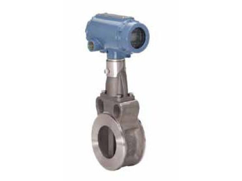
Расходомеры-счётчики вихревые 8800 предназначены для измерения расхода и количества газа, пара или жидкости.
Описание
Принцип работы расходомеров-счётчиков вихревых 8800 основан на создании в потоке движущейся по трубопроводу среды устойчивых вихрей, частота срыва которых пропорциональна скорости потока.
Расходомеры-счётчики вихревые 8800 состоят из следующих функциональных блоков:
— тела обтекания, создающего вихревую дорожку;
— пьезоэлектрического сенсора воспринимающего колебания среды;
— электронного блока, выполняющего расчёт скорости, объёма, расхода потока;
— встроенного индикатора (при наличии), отображающего измеренные величины. Измеренные данные могут передаваться в систему верхнего уровня по частотноимпульсному выходному сигналу, по токовому выходному сигналу с коммуникацией по протоколу HART, по протоколу FOUNDATION fieldbus.
Расходомеры-счётчики вихревые 8800 имеют следующие исполнения:
— 8800DW — бесфланцевый;
— 8800DF — фланцевый;
— 8800DR — со встроенными коническими переходами (только фланцевого типа);
— 8800DD — сдвоенный (только фланцевого типа).
Электронный блок может монтироваться отдельно от первичного преобразователя, с которым соединяется кабелем.
а) б) в) г)
Программное обеспечение
Алгоритм, реализующий функции расчёта скорости, объёма, расхода потока, цифроаналоговое преобразование измеренных величин в значения тока и частоты на выходе, а также вывод данных на индикатор и через цифровые интерфейсы, выполнен на микросхеме ROM с использованием маски (фотошаблон). ПО, встроенное в микросхему, не изменяемое и не считываемое.
Уровень защиты программного обеспечения расходомеров-счётчиков вихревых 8800 от непреднамеренных и преднамеренных изменений «С» по МИ 3286-2010.
Технические характеристики
Таблица 1- Метрологические и технические характеристики
|
Наименование параметра |
Значение |
|
Диаметр условный, Ду, мм |
15, 25, 40, 50, 80, 100, 150, 200, 250, 300 |
|
Диапазоны расхода, Q: — жидкость, м3/ч — газ, м3/ч — пар, кг/ч |
от 0,4 до 2002,0 от 1,4 до 20016,0 от 5,8 до 355968,0 |
|
Пределы допускаемой относительной погрешности измерений объёмного расхода, % — жидкости с Re > 20000 для всех исполнений, кроме 8800DR Ду от 150 до 300 мм — жидкости с Re > 20000 для исполнений 8800DR Ду от 150 до 300 мм — газа и пара с Re > 15000 для всех исполнений, кроме 8800DR Ду от 150 до 300 мм — газа и пара с Re > 15000 для исполнений 8800DR Ду от 150 до 300 мм — жидкости (газа и пара) с 20000 (15000) > Re > 10000 — жидкости, газа и пара с 10000 > Re > 5000 |
±0,65 ±1,0 ±1,0 ±1,35 ±2,0 ±6,0 |
|
Пределы допускаемой основной приведённой погрешности преобразования расхода в токовый выходной сигнал, % |
±0,025 |
|
Пределы допускаемой дополнительной приведённой погрешности преобразования расхода в токовый выходной сигнал, вызванной изменением температуры окружающей среды от (25 ± 5) °С до температуры в диапазоне от минус 50 °С до +85 °С, на каждые 10 °С, % |
±0,01 |
|
Выходной токовый сигнал |
от 4 до 20 мА |
|
Частотно-импульсный выходной сигнал |
от 0 до 10 кГц |
|
Цифровой интерфейс |
Foundation Fieldbus, HART, Wireless HART |
|
Потеря давления, кПа, не более |
45 |
|
Максимальное давление рабочей среды, МПа |
25 |
|
Температура измеряемой среды, °С |
от минус 200 до +427 |
|
Напряжение питания постоянного тока, В |
от 10,8 до 42,0 |
|
Потребляемая мощность, Вт, не более |
1 |
|
Габаритные размеры, мм |
от 102x247x130 до 686x774x585 |
|
Масса, кг |
от 3,3 до 305 |
|
Условия эксплуатации: — температура окружающей среды, °С; — ЖКИ работоспособен при температуре окружающей среды,°С; — относительная влажность, %; — атмосферное давление, кПа |
от минус 50 до +85 от минус 20 до +85 до 95 от 84,0 до 106,7 |
Знак утверждения типа
наносят на корпус расходомеров-счётчиков вихревых 8800 методом наклейки и титульный лист руководства по эксплуатации типографским способом.
Комплектность
Таблица 2 — Комплектность средства измерений.
|
Наименование |
Количество |
|
Расходомер-счётчик вихревой |
1 |
|
Руководство по эксплуатации |
1 |
|
Методика поверки |
1 |
|
Комплект ЗИП |
По заказу |
Сведения о методах измерений
приведены в руководстве по эксплуатации расходомеров-счётчиков вихревых 8800.
Поверка
осуществляется по документу МП 14663-12 «Расходомеры-счётчики вихревые 8800. Методика поверки», утвержденному ГЦИ СИ ФБУ «Ростест-Москва» 29 августа 2011 г.
При поверке применяются следующие средства измерений:
— установка для поверки расходомеров с пределами допускаемой относительной погрешности ±0,2 % для жидкостей или ±0,4 % для газов, диапазон расходов в соответствии с диапазоном расходов поверяемого расходомера-счётчика;
— штангенциркуль, диапазон измерений от 0 до 300 мм, ПГ ±0,01 мм;
— генератор сигналов низкочастотный, диапазон частот от 5 до 10000 Гц, амплитуда сигнала от 2 до 5 В, форма сигнала: синусоидальная и прямоугольная;
— частотомер электронно-счётный, диапазон частот от 5 до 10000 Гц, ПГ ±10-6;
— миллиамперметр, диапазон измерений от 4 до 20 мА, ПГ ±0,02 % от диапазона.
Нормативные и технические документы, устанавливающие требования к расходомерам-счётчикам вихревым 8800
Техническая документация «Emerson Process Management / Rosemount Inc.» (США).
Рекомендации к применению
Осуществление производственного контроля за соблюдением установленных законодательством Российской Федерации требований промышленной безопасности к эксплуатации опасного производственного объекта; осуществление торговли и товарообменных операций; выполнении работ по оценке соответствия промышленной продукции и продукции других видов, а также иных объектов установленным законодательством Российской Федерации обязательным требованиям.

00825-0107-400 DB 1 Rosemount 8800
www.rosemount.com

Rosemount 880000825-0107-
2
© 2011
the
8200 Market Boulevard Neonstraat 1Chanhassen, MN USA 55317 6718 WX Ede
-522-6277 The Netherlands 1 Pandan Crescent-5200 T +31 (0)318 495555 Singapore 128461
-8889 T (65) 6777 8211
0743
—
—0100-
www.rosemount.com.
—
— Rosemount 8800 , .
— .
—
/

00825-0107-400 DB 1 Rosemount 8800
3
—
.
—
.
—
,
-°F (85
°F (85 °C).

Rosemount 880000825-0107-
4
/ -Rosemount 8800
185 °F (85 °C).
— .
—
-0100-

00825-0107-400 DB 1 Rosemount 8800
5
—
— .
—
3…5 D
3…5 D

Rosemount 880000825-0107-
6
.
—
-1(« »).
— .
— .
1/21/4
, R33, R50 -1. —
2.
.
SST

00825-0107-400 DB 1 Rosemount 8800
7
1.
( ).
2.
3.4.
5.6.7.8.9.
1.
2. .
3.
4.5.

Rosemount 880000825-0107-
8
6.7.
.
—
.
-.
Foundation fieldbus
.

00825-0107-400 DB 1 Rosemount 8800
9
%.
. .
-fieldbus
fieldbus.
— —
. —
—

Rosemount 880000825-0107-
10
— : 1.2. «+»
«-»
3.«+»
«-» 13.
— /
24
°F (60 °F (90 °C).
—
— Rosemount 8800 c Foundation fieldbus.4.
-1/2 -14 NPT.
5.
— .
— Rosemou
—

00825-0107-400 DB 1 Rosemount 8800
11
-HART
—
— /
+
—
+
—
+
—

Rosemount 880000825-0107-
12
-Rosemount 8800.
-Foundation fieldbus
1.2.
3.
4. 1/2.
5.
)

00825-0107-400 DB 1 Rosemount 8800
13
— Ro
-Rosemount
Rosemount
• •
K
• •• •
— —
•

Rosemount 880000825-0107-
14
« »
1, 4, 2, 1, 3 1, 4, 1, 51, 4, 2, 1 1, 3, 8, 31, 4, 3, 1, 4 — 1, 4, 2, 3, 2
1, 1, 4, 1, 3, 2 1, 4, 2, 3, 1
1, 1, 4, 1, 3, 1 1, 3, 2, 2
1, 4, 2, 3, 4 1, 11, 4, 2, 3, 5 1, 4, 2, 2, 11, 4, 2, 3, 6, 1 1, 4, 2, 2, 21, 4, 2, 3, 6, 2 1, 3, 9
1, 4, 2, 3, 6, 3 1, 3, 6, 1
1, 4, 2, 3, 6, 4 1, 1, 2
1, 4, 2, 3, 6 1, 3, 6, 4
1, 1, 4, 1, 3, 4 1, 3, 81, 2, 5 1, 51, 4, 4, 5 1, 4, 4, 71, 4, 4, 3 1, 2, 6
1, 3, 2, 4, 1, 1 1, 2, 1, 51, 4, 4, 7, 6 — 1, 4, 3, 2, 21, 1, 4, 7, 1 / 1, 1, 4, 1, 21, 1, 4, 7, 2 1, 1, 4, 1, 3
1, 4, 3, 3 1, 2, 1, 11, 4, 4, 7, 5 1, 3, 6, 2
1, 3, 2, 4, 2 1, 3, 11, 3, 2, 3 1, 1, 4, 4, 1
1, 3, 4 1, 1, 4, 41, 2, 4 1, 3, 2, 11, 4, 1, 6 1, 3, 6, 3
1, 3, 3 1, 4, 3, 2, 51, 4, 2, 4 1, 3, 8, 11, 2, 2 1, 1, 4, 1, 3, 31, 4, 3, 2, 3 1, 3, 8, 4
1, 4, 3, 2, 4 1, 1, 4, 61, 3, 8, 2 1, 3, 61, 3, 8, 5 1, 1, 4, 31, 4, 4, 1 1, 1, 4, 3, 31, 1, 4, 2, 1 1, 1, 4, 11, 1, 4, 2, 2 1, 4, 1, 4
1, 3, 5 1, 4, 4, 6
1, 4, 4, 4
— Rosemount 8800 (00809-0100-4004).

00825-0107-400 DB 1 Rosemount 8800
15
3
HART
1, 3, 1, 3, 2 3, 4, 3, 2
3, 4, 3, 1 2, 2, 7, 13, 4, 3, 6 2, 1, 4, 1
2, 2, 2, 3, 2 2, 2, 2, 1, 1
2, 2, 2, 3, 1 2, 2, 2, 2, 6
2, 2, 7, 2 2, 2, 1, 1, 22, 2, 7, 3 2, 2, 3, 1, 22, 2, 7, 4, 1 3, 2, 12, 2, 7, 4, 2 3, 2, 4, 42, 2, 7, 4, 3 3, 5, 3, 42, 2, 7, 4, 4 3, 4, 3, 82, 2, 7, 4, 5 2, 2, 1, 2, 1
2, 2, 1, 2, 2 3, 4, 1, 2
2, 2, 2, 3, 4 2, 1, 4, 6
2, 2, 8, 2, 1 2, 2, 8, 32, 2, 8, 2, 2 3, 4, 3, 7
2, 2, 3, 3, 2 2- 2, 2, 2, 1, 22, 2, 8, 1, 5 3, 4, 1, 12, 1, 1, 2 2, 2, 2, 1, 5
3, 2, 5, 4 3, 2, 4, 22, 2, 2, 2, 5 3, 2, 5, 2
2, 2, 8, 1, 4 2, 2, 2, 3, 52, 2, 1, 1, 5 2, 2, 2, 3, 32, 2, 1, 1, 4 1, 1, 1
2, 2, 1, 4, 2 2, 2, 8, 1, 13, 5, 1 3- 2, 2, 2, 1, 3
4- 2, 2, 2, 1, 4 1, 3, 6, 12, 2, 1, 1, 7 1, 3, 6, 32, 2, 4, 1, 4 1, 3, 6, 22, 2, 4, 1, 5, 2 2, 2, 1, 1, 13, 5, 2, 6 2, 1, 4, 52, 1, 4, 3 2, 2, 4, 1, 32, 1, 4, 4 2, 2, 4, 1, 5, 12, 2, 8, 1, 2 3, 2, 3, 43, 2, 3, 6 2, 2, 2, 2, 22, 2, 2, 2, 4 2, 2, 2, 2, 32, 2, 1, 1, 6 3, 2, 3, 22, 2, 8, 2, 3 2, 2, 2, 2, 12, 2, 1, 4, 5 2, 2, 1, 4, 1
2, 2, 4, 1, 6 2, 2, 8, 1, 62, 1, 1, 3

Rosemount 880000825-0107-
16
Rosemount Inc. – Eden Prairie, Minnesota, USAEmerson Process Management BV – Ede, The Netherlands ( ) Emerson Process Management Flow Technologies Company, Ltd – Nanjing, Jiangsu
Province, P.R. China ( )
• —
•
1/2-14 NPT.
—
— www.rosemount.com
-2009-CE-HOU-DNV0575
— .
— —
—

00825-0107-400 DB 1 Rosemount 8800
17
(-50 °C a °C)
08800-0116-50 °C a °C) 4—50 °C a °C) Fieldbus
D
-50 °C a °C)-0116.
I5
;
I, 1, Ex d[ia] IIC CSA 06.1674267-50 °C a °C)
D -50 °C a °C) 4—50 °C a °C) Fieldbus

Rosemount 880000825-0107-
18
D;
-50 °C a °C)-0112.
EN 60079-0: 2009EN 60079-11: 2007
II 1 GEx ia IIC T4 Ga (-60 °C a °C) 4-20 HART
(-60 °C a °C) Fieldbus
4- HART Fieldbus
Ui Ui
Ii(1) Ii
Pi(1) Pi
Ci Ci
Li Li
(1)
0575
84X
II 1 GEx ia IIC T4 Ga (-60 °C a °C)
0575
Ui
IiPi = 5,32 Ci = 0 Li < 10

00825-0107-400 DB 1 Rosemount 8800
19
;
,
EN 60079-0: 2009EN 60079-11: 2007EN 60079-15: 2010
05ATEX0085X
II 3 GEx nA ic IIC T5 Gc (-50 °C a °C) 4 -20 HART
(-50 °C a °C) Fieldbus
— HART
,
EN 60079-0: 2009EN 60079-1: 2007EN 60079-11: 2007

Rosemount 880000825-0107-
20
:
II 1/2 GEx d [ia] IIC T6 Ga/Gb(-50 °C a °C)
:
II 2(1) GEx d [ia] IIC T6 Ga/Gb(-50 °C a °C)
II 1 G Ex ia IIC T6 Ga- HART
. Fieldbus
°C,
-202 °-50 °C.
— -7A4-70.
EN 60241-0: 2006EN 60241-1: 2004
II 1D Ex tD A20 IP66 T90 °C (-20 °C a °C) —
D

00825-0107-400 DB 1 Rosemount 8800
21
IEC 60079-0: 2007IEC 60079-11: 2006
Ex ia IIC T4 Ga (-60 °C a °C) 4-20 HART(-60 °C a °C) Fieldbus
4- HART Fieldbus
Ui Ui
Ii(1) Ii
Pi(1) Pi
Ci Ci
Li Li
(1)
Ex ia IIC T4 Ga (-60 °C a °C) : Ui = 17,5
Ii = 380 Pi = 5,32 Ci = 0 Li
;
,

Rosemount 880000825-0107-
22
IEC 60079-0: 2007IEC 60079-11: 2006IEC 60079-15: 2010
IECEx BAS05.0029XEx nA ic IIC T5 Gc (-40 °C a °C) 4-20 HART
(-40 °C a °C) Fieldbus- HART
Fieldbus
,
IEC 60079-0: 2007-10IEC 60079-1: 2007-04IEC 60079-11: 2006 IEC 60079-26: 2006
IECEx KEM05.0017X
Ex d [ia] IIC T6 Ga/Gb(-50 °C a °C)
Ex d [ia] IIC T6 Ga/Gb(-50 °C a °C)
Ex ia IIC T6 Ga-
°C,

00825-0107-400 DB 1 Rosemount 8800
23
-202-50 +70 °C.
— -A4-
-202 7 —
50 °C.
GYJ071327X-50 °C)
Ex ia IIC T4/T5T4: -60 °C)
-60 °C)
Ui
IiPi = 1,0 Ci = 0 Li = 0,97
GYJ071193X-40 °C)
.

Rosemount 880000825-0107-
24
— Ex d [ia] T6
– Ex ia IIC T6
TC17816 MTATC17817 MTATC17905 MTATC17906

00825-0107-400 DB 1 Rosemount 8800
25
,

Rosemount 880000825-0107-
26
EN 61326-1:2006
Q – -2009-CE-HOU-DNV
ASME B31.3:2008
Sound Engineering PracticeASME B31.3:2008
) EN 60079-0:2009EN 60079-11: 2007
) EN 60079-0:2009EN 60079-11:2007EN 60079-15: 2010
1 D (Ex tD A20 IP66 T90º)EN 61241-0:2006EN 61241-1:2004

00825-0107-400 DB 1 Rosemount 8800
27
–
–
1 G (Ex ia IIC T6 Ga) – EN 60079-0:2009EN 60079-1:2007EN 60079-11:2007EN 60079-26:2007
Veritasveien 1, N-1322Hovik, Norway
Utrechtseweg 310, 6812 AR ArnhemP.O. Box 5185, 6802 ED ArnhemThe NetherlandsPostbank 6794687
: 1180]Rlockhead Business Park, Staden LaneBuxton, Derbyshire SK17 9RZ United Kingdom
Veritasveien 1, N-1322Hovik, Norway
FILE: ID. 8800D CE Marking 8800D_RFD1029K.DOCX|

Rosemount 880000825-0107-
28
Содержание
- Расходомеры-счетчики вихревые 8800
- Скачать
- Информация по Госреестру
- Назначение
- Описание
- Программное обеспечение
- Технические характеристики
- Знак утверждения типа
- Комплектность
- Сведения о методах измерений
- Поверка
- Рекомендации к применению
- Rosemount 8800 руководство по монтажу
Расходомеры-счетчики вихревые 8800

Расходомеры-счётчики вихревые 8800 предназначены для измерения расхода и количества газа, пара или жидкости.
Скачать
Информация по Госреестру
| Номер в ГРСИ РФ: | 14663-12 |
|---|---|
| Категория: | Расходомеры |
| Производитель / заявитель: | Фирма «Emerson Process Management GmbH & Co. OHG», Германия |
| Поставщик: |
| Основные данные | |
|---|---|
| Номер по Госреестру | 14663-12 |
| Наименование | Расходомеры-счетчики вихревые |
| Модель | 8800 |
| Класс СИ | 29.01.02 |
| Год регистрации | 2012 |
| Методика поверки / информация о поверке | МП 14663-12 |
| Межповерочный интервал / Периодичность поверки | 4 года |
| Страна-производитель | Нидерланды |
| Информация о сертификате | |
| Срок действия сертификата | 26.06.2017 |
| Номер сертификата | 46878 |
| Тип сертификата (C — серия/E — партия) | C |
| Дата протокола | Приказ 443 п. 24 от 26.06.2012 |
Производитель / Заявитель
Фирма «Emerson Process Management Flow B. V.», Нидерланды
Назначение
Расходомеры-счётчики вихревые 8800 предназначены для измерения расхода и количества газа, пара или жидкости.
Описание
Принцип работы расходомеров-счётчиков вихревых 8800 основан на создании в потоке движущейся по трубопроводу среды устойчивых вихрей, частота срыва которых пропорциональна скорости потока.
Расходомеры-счётчики вихревые 8800 состоят из следующих функциональных блоков:
— тела обтекания, создающего вихревую дорожку;
— пьезоэлектрического сенсора воспринимающего колебания среды;
— электронного блока, выполняющего расчёт скорости, объёма, расхода потока;
— встроенного индикатора (при наличии), отображающего измеренные величины. Измеренные данные могут передаваться в систему верхнего уровня по частотноимпульсному выходному сигналу, по токовому выходному сигналу с коммуникацией по протоколу HART, по протоколу FOUNDATION fieldbus.
Расходомеры-счётчики вихревые 8800 имеют следующие исполнения:
— 8800DR — со встроенными коническими переходами (только фланцевого типа);
— 8800DD — сдвоенный (только фланцевого типа).
Электронный блок может монтироваться отдельно от первичного преобразователя, с которым соединяется кабелем.
Программное обеспечение
Алгоритм, реализующий функции расчёта скорости, объёма, расхода потока, цифроаналоговое преобразование измеренных величин в значения тока и частоты на выходе, а также вывод данных на индикатор и через цифровые интерфейсы, выполнен на микросхеме ROM с использованием маски (фотошаблон). ПО, встроенное в микросхему, не изменяемое и не считываемое.
Уровень защиты программного обеспечения расходомеров-счётчиков вихревых 8800 от непреднамеренных и преднамеренных изменений «С» по МИ 3286-2010.
Технические характеристики
Таблица 1- Метрологические и технические характеристики
Диаметр условный, Ду, мм
15, 25, 40, 50, 80, 100, 150, 200, 250, 300
Диапазоны расхода, Q:
от 0,4 до 2002,0 от 1,4 до 20016,0 от 5,8 до 355968,0
Пределы допускаемой относительной погрешности измерений объёмного расхода, %
— жидкости с Re > 20000 для всех исполнений, кроме 8800DR Ду от 150 до 300 мм
— жидкости с Re > 20000 для исполнений 8800DR Ду от 150 до 300 мм
— газа и пара с Re > 15000 для всех исполнений, кроме 8800DR Ду от 150 до 300 мм
— газа и пара с Re > 15000 для исполнений 8800DR Ду от 150 до 300 мм
— жидкости (газа и пара) с 20000 (15000) > Re > 10000
— жидкости, газа и пара с 10000 > Re > 5000
Пределы допускаемой основной приведённой погрешности преобразования расхода в токовый выходной сигнал, %
Пределы допускаемой дополнительной приведённой погрешности преобразования расхода в токовый выходной сигнал, вызванной изменением температуры окружающей среды от (25 ± 5) °С до температуры в диапазоне от минус 50 °С до +85 °С, на каждые 10 °С, %
Выходной токовый сигнал
Частотно-импульсный выходной сигнал
Foundation Fieldbus, HART, Wireless HART
Потеря давления, кПа, не более
Максимальное давление рабочей среды, МПа
Температура измеряемой среды, °С
от минус 200 до +427
Напряжение питания постоянного тока, В
Потребляемая мощность, Вт, не более
Габаритные размеры, мм
от 102x247x130 до 686x774x585
— температура окружающей среды, °С;
— ЖКИ работоспособен при температуре окружающей среды,°С;
— атмосферное давление, кПа
от минус 50 до +85 от минус 20 до +85 до 95 от 84,0 до 106,7
Знак утверждения типа
наносят на корпус расходомеров-счётчиков вихревых 8800 методом наклейки и титульный лист руководства по эксплуатации типографским способом.
Комплектность
Таблица 2 — Комплектность средства измерений.
Руководство по эксплуатации
Сведения о методах измерений
приведены в руководстве по эксплуатации расходомеров-счётчиков вихревых 8800.
Поверка
осуществляется по документу МП 14663-12 «Расходомеры-счётчики вихревые 8800. Методика поверки», утвержденному ГЦИ СИ ФБУ «Ростест-Москва» 29 августа 2011 г.
При поверке применяются следующие средства измерений:
— установка для поверки расходомеров с пределами допускаемой относительной погрешности ±0,2 % для жидкостей или ±0,4 % для газов, диапазон расходов в соответствии с диапазоном расходов поверяемого расходомера-счётчика;
— штангенциркуль, диапазон измерений от 0 до 300 мм, ПГ ±0,01 мм;
— генератор сигналов низкочастотный, диапазон частот от 5 до 10000 Гц, амплитуда сигнала от 2 до 5 В, форма сигнала: синусоидальная и прямоугольная;
— частотомер электронно-счётный, диапазон частот от 5 до 10000 Гц, ПГ ±10-6;
— миллиамперметр, диапазон измерений от 4 до 20 мА, ПГ ±0,02 % от диапазона.
Нормативные и технические документы, устанавливающие требования к расходомерам-счётчикам вихревым 8800
Техническая документация «Emerson Process Management / Rosemount Inc.» (США).
Рекомендации к применению
Осуществление производственного контроля за соблюдением установленных законодательством Российской Федерации требований промышленной безопасности к эксплуатации опасного производственного объекта; осуществление торговли и товарообменных операций; выполнении работ по оценке соответствия промышленной продукции и продукции других видов, а также иных объектов установленным законодательством Российской Федерации обязательным требованиям.
Источник
Rosemount 8800 руководство по монтажу
СКАЧАТЬ: kursovaya.zip [226,35 Kb] (cкачиваний: 109)
ВВЕДЕНИЕ
Развитие науки, управление технологическими процессами немыслимы без получения количественной информации о тех или иных свойствах физических объектов.
Измерение представляет собой информационный процесс, результатом которого является получение измерительной информации, т.е. количественной информации об измеряемых величинах.
Все средства измерений определяются как технические средства, используемые при измерениях и имеющие нормированные метрологические характеристики.
Знание основ теории измерения, устройства и основных правил эксплуатации контрольно-измерительных приборов является в настоящее время непременным условием правильного ведения технологических процессов бурения, добычи, транспорта и переработки нефти и газа.
Измерение количества и расхода вещества необходимо для контроля и управления технологическими процессами нефтегазодобывающих предприятий.
При измерении расхода и количества вещества приходится иметь дело с движущейся жидкостью. Жидкостями в гидравлике считают физические тела находящиеся как в жидком, так и в газообразном состоянии и легко изменяющие свою форму под действием сил самой незначительной величины.
Основными характеристиками движущейся жидкости являются: гидродинамическое давление p, скорость движения движущихся частиц W и плотность жидкости p.
Расход – это масса или объем вещества, проходящего через данное сечение канала средства измерения расхода в единицу времени. Расход бывает объемной либо массовой.
Расходом вещества в данный момент называется отношение приращения количества вещества (dV или dg), протекающего в данный момент времени dt при условии, что dt стремится к нулю, следовательно, объемный расход Q=dV/dt , а весовой расход Qg=dG/dt .
Вихревые расходомеры применяются для измерения расхода жидкостей, газов и пара. Они распространены очень широко и используются во многих отраслях: от сферы жилищно-коммунального хозяйства для тепло- и водоучета до химической, нефтеперерабатывающей, пищевой промышленности в сложных технологических процессах.
При определенных условиях движения потока среды часть кинетической энергии потока может преобразовываться в пульсации (завихрения). Частота следования этих пульсаций пропорциональна скорости потока.
Общие характеристики для большей части вихревых расходомеров:
- · Стандартный выходной частотный сигнал.
- · Широкий динамический диапазон (от 1:10 до 1:40).
- · Достаточно высокая точность измерений.
- · Независимость точности измерения расхода от изменений температуры, давления и плотности измеряемой среды.
- · Высокая повторяемость и стабильность показаний.
- · Простота конструкции, легкость в монтаже, низкая стоимость обслуживания.
- · Универсальность принципа – измерение жидкостей, газа и пара.
Существует несколько основных типов вихревых расходомеров, отличающихся по способу образования вихрей. Наиболее распространен тип, у которого поперек потока измеряемой среды установлено плохообтекаемое тело (тело обтекания, вихревое тело, вихреобразователь), за которым поочередно с разных сторон образуются вихри.
В 1878 году Струхаль (Strouhal) экспериментально доказал существование зависимости между частотой пульсаций потока и скоростью течения среды. Долгое время изучением явлений пульсаций потока и вихреобразования занимались только в целях их предотвращения, т. к. эти явления (особенно при высокой температуре измеряемой среды) могут спровоцировать возникновение гидроударов и термоударов и, в конечном итоге, привести к повреждению оборудования.
Применение пульсаций вихрей для измерения расхода началось только в 50-х годах XX века. К 60 годам были разработаны термический и термоанемометрический методы детектирования вихрей для измерения расхода в трубопроводах. Так появились первые вихревые расходомеры.
В период 70-80-х годов развитие вихревой расходометрии происходило весьма быстро, было разработано множество методов возмущения потока (вихреобразования) и детектирования вихрей, на рынке появилось большое количество приборов.
Принцип действия
При обтекании потоком неподвижного препятствия (тела обтекания) образуются вихри. Образование вихрей и их отрыв от тела обтекания происходит поочередно с разных его сторон.
Рис.1. Принцип работы вихревых расходомеров
Развитие вихря с одной стороны препятствует его образованию с противоположной стороны. За телом обтекания образуется двойная дорожка из вихрей, называемая «дорожкой Кармана».
Частота вихреобразования (частота отрыва вихрей) пропорциональна скорости потока, а значит и расходу. Зависимость между частотой вихреобразования и скоростью (расходом) определяется критерием Струхаля:
где f – частота вихреобразования,
d – характерный размер тела обтекания,
W – средняя скорость потока.
Частота вихреобразования определяется формулой:
Для характеристики вихревых расходомеров вместо числа Струхаля используется К-фактор. Производители под К-фактором подразумевают либо:
Число вихрей, приходящихся на единицу объема среды:
Объем среды, приходящийся на один вихрь:
где n – число вихрей за время t; V – объем среды за время t.
Основное уравнение вихревого расходомера:
К-фактор условно постоянен в определенном диапазоне чисел Re и не зависит от плотности, вязкости, скорости потока и др. свойств среды. Диапазон чисел Рейнольдса, при которых К-фактор постоянен, называется рабочей областью (областью измерений) вихревых расходомеров.
Конструкция
В общем виде, вихревой расходомер состоит из двух частей: первичного преобразователя и вторичного преобразователя (электронного блока или конвертера).
Рис.3. Общие элементы конструкции вихревых расходомеров
Первичный преобразователь включает в себя вихреобразователь (тело обтекания) и устройство детектирования вихрей (сенсор). Электронный блок состоит из фильтра, усилителя, АЦП и схемы выходных сигналов. С развитием микропроцессорной электроники появились интеллектуальные вихревые расходомеры, в которых сигнал с АЦП проходит обработку. Помимо улучшения точности измерения и сведения к минимуму влияний факторов температуры, давления, нелинейности К-фактора, неравномерности потока и др., появилась возможность использования цифровой коммуникации и добавления дополнительной функциональности (например, функции вычислителя-счетчика) в расходомере.
Вихреобразователь или вихревое тело – это один из главных компонентов первичного преобразователя, во многом определяющий метрологические характеристики расходомера (линейность и повторяемость, пределы измерения) и потери давления. В целом, при выборе оптимального вихреобразователя, производители расходомеров руководствуются следующими требованиями:
- · вихри не должны пересекаться для их однозначного детектирования;
- · генерация вихрей должна быть стабильна (постоянство числа Струхаля) в широком диапазоне чисел Рейнольдса;
- · вихри должны быть достаточно сильными для детектирования, должно быть высокое соотношение сигнал-шум;
- · форма и структура тела обтекания должна быть достаточно простой и технологичной;
- · геометрия и материал исполнения тела обтекания должны исключать влияние коррозии и температуры на метрологические характеристики прибора;
- · спектр частот вихрей как жидкостей, так и газов не должен перекрываться со спектром естественных и промышленных частот (вибрация трубопровода, частота самовозбуждения сенсора и др.).
Существует достаточно большое число разновидностей вихреобразователей, которые можно разделить на две группы: состоящие из одной части и состоящие из двух и более частей.
Наиболее распространенными являются вихревые тела, состоящие из одной части, такие, как цилиндрическое, прямоугольное, треугольное и трапециевидное тела.
Рис.4. Простые тела обтекания.
Некоторые производители используют более сложные многосоставные тела обтекания.
Рис.5. Сложные составные тела обтекания.
Методы детектирования вихрей
Методов детектирования вихрей достаточно много, однако наибольшее распространение получили следующие:
- Детектирование пульсации вихрей (вихревые расходомеры пульсаций давления и вихревые расходомеры изгибных напряжений).
- Детектирование вихрей с помощью изменения электрической емкости чувствительного элемента (вихревые емкостные расходомеры).
- Детектирование вихрей с помощью ультразвуковых волн (вихреакустические расходомеры).
- Терморезистивный и термоанемометрический метод детектирования (термальные вихревые расходомеры).
- Электромагнитное детектирование вихрей (вихревые электромагнитные расходомеры).
Основные характеристики вихревых расходомеров с различными методами съема сигнала представлены в таблицах:
Тип расходомера
Простота
конструкции
Ремонто-
пригод-
ность
Чувстви-
тельность
Стойкость
к термо-
ударам
Источник

00825-0107-400 DB 1 Rosemount 8800
www.rosemount.com

Rosemount 880000825-0107-
2
© 2011
the
8200 Market Boulevard Neonstraat 1Chanhassen, MN USA 55317 6718 WX Ede
-522-6277 The Netherlands 1 Pandan Crescent-5200 T +31 (0)318 495555 Singapore 128461
-8889 T (65) 6777 8211
0743
—
—0100-
www.rosemount.com.
—
— Rosemount 8800 , .
— .
—
/

00825-0107-400 DB 1 Rosemount 8800
3
—
.
—
.
—
,
-°F (85
°F (85 °C).

Rosemount 880000825-0107-
4
/ -Rosemount 8800
185 °F (85 °C).
— .
—
-0100-

00825-0107-400 DB 1 Rosemount 8800
5
—
— .
—
3…5 D
3…5 D

Rosemount 880000825-0107-
6
.
—
-1(« »).
— .
— .
1/21/4
, R33, R50 -1. —
2.
.
SST

00825-0107-400 DB 1 Rosemount 8800
7
1.
( ).
2.
3.4.
5.6.7.8.9.
1.
2. .
3.
4.5.

Rosemount 880000825-0107-
8
6.7.
.
—
.
-.
Foundation fieldbus
.

00825-0107-400 DB 1 Rosemount 8800
9
%.
. .
-fieldbus
fieldbus.
— —
. —
—

Rosemount 880000825-0107-
10
— : 1.2. «+»
«-»
3.«+»
«-» 13.
— /
24
°F (60 °F (90 °C).
—
— Rosemount 8800 c Foundation fieldbus.4.
-1/2 -14 NPT.
5.
— .
— Rosemou
—

00825-0107-400 DB 1 Rosemount 8800
11
-HART
—
— /
+
—
+
—
+
—

Rosemount 880000825-0107-
12
-Rosemount 8800.
-Foundation fieldbus
1.2.
3.
4. 1/2.
5.
)

00825-0107-400 DB 1 Rosemount 8800
13
— Ro
-Rosemount
Rosemount
• •
K
• •• •
— —
•

Rosemount 880000825-0107-
14
« »
1, 4, 2, 1, 3 1, 4, 1, 51, 4, 2, 1 1, 3, 8, 31, 4, 3, 1, 4 — 1, 4, 2, 3, 2
1, 1, 4, 1, 3, 2 1, 4, 2, 3, 1
1, 1, 4, 1, 3, 1 1, 3, 2, 2
1, 4, 2, 3, 4 1, 11, 4, 2, 3, 5 1, 4, 2, 2, 11, 4, 2, 3, 6, 1 1, 4, 2, 2, 21, 4, 2, 3, 6, 2 1, 3, 9
1, 4, 2, 3, 6, 3 1, 3, 6, 1
1, 4, 2, 3, 6, 4 1, 1, 2
1, 4, 2, 3, 6 1, 3, 6, 4
1, 1, 4, 1, 3, 4 1, 3, 81, 2, 5 1, 51, 4, 4, 5 1, 4, 4, 71, 4, 4, 3 1, 2, 6
1, 3, 2, 4, 1, 1 1, 2, 1, 51, 4, 4, 7, 6 — 1, 4, 3, 2, 21, 1, 4, 7, 1 / 1, 1, 4, 1, 21, 1, 4, 7, 2 1, 1, 4, 1, 3
1, 4, 3, 3 1, 2, 1, 11, 4, 4, 7, 5 1, 3, 6, 2
1, 3, 2, 4, 2 1, 3, 11, 3, 2, 3 1, 1, 4, 4, 1
1, 3, 4 1, 1, 4, 41, 2, 4 1, 3, 2, 11, 4, 1, 6 1, 3, 6, 3
1, 3, 3 1, 4, 3, 2, 51, 4, 2, 4 1, 3, 8, 11, 2, 2 1, 1, 4, 1, 3, 31, 4, 3, 2, 3 1, 3, 8, 4
1, 4, 3, 2, 4 1, 1, 4, 61, 3, 8, 2 1, 3, 61, 3, 8, 5 1, 1, 4, 31, 4, 4, 1 1, 1, 4, 3, 31, 1, 4, 2, 1 1, 1, 4, 11, 1, 4, 2, 2 1, 4, 1, 4
1, 3, 5 1, 4, 4, 6
1, 4, 4, 4
— Rosemount 8800 (00809-0100-4004).

00825-0107-400 DB 1 Rosemount 8800
15
3
HART
1, 3, 1, 3, 2 3, 4, 3, 2
3, 4, 3, 1 2, 2, 7, 13, 4, 3, 6 2, 1, 4, 1
2, 2, 2, 3, 2 2, 2, 2, 1, 1
2, 2, 2, 3, 1 2, 2, 2, 2, 6
2, 2, 7, 2 2, 2, 1, 1, 22, 2, 7, 3 2, 2, 3, 1, 22, 2, 7, 4, 1 3, 2, 12, 2, 7, 4, 2 3, 2, 4, 42, 2, 7, 4, 3 3, 5, 3, 42, 2, 7, 4, 4 3, 4, 3, 82, 2, 7, 4, 5 2, 2, 1, 2, 1
2, 2, 1, 2, 2 3, 4, 1, 2
2, 2, 2, 3, 4 2, 1, 4, 6
2, 2, 8, 2, 1 2, 2, 8, 32, 2, 8, 2, 2 3, 4, 3, 7
2, 2, 3, 3, 2 2- 2, 2, 2, 1, 22, 2, 8, 1, 5 3, 4, 1, 12, 1, 1, 2 2, 2, 2, 1, 5
3, 2, 5, 4 3, 2, 4, 22, 2, 2, 2, 5 3, 2, 5, 2
2, 2, 8, 1, 4 2, 2, 2, 3, 52, 2, 1, 1, 5 2, 2, 2, 3, 32, 2, 1, 1, 4 1, 1, 1
2, 2, 1, 4, 2 2, 2, 8, 1, 13, 5, 1 3- 2, 2, 2, 1, 3
4- 2, 2, 2, 1, 4 1, 3, 6, 12, 2, 1, 1, 7 1, 3, 6, 32, 2, 4, 1, 4 1, 3, 6, 22, 2, 4, 1, 5, 2 2, 2, 1, 1, 13, 5, 2, 6 2, 1, 4, 52, 1, 4, 3 2, 2, 4, 1, 32, 1, 4, 4 2, 2, 4, 1, 5, 12, 2, 8, 1, 2 3, 2, 3, 43, 2, 3, 6 2, 2, 2, 2, 22, 2, 2, 2, 4 2, 2, 2, 2, 32, 2, 1, 1, 6 3, 2, 3, 22, 2, 8, 2, 3 2, 2, 2, 2, 12, 2, 1, 4, 5 2, 2, 1, 4, 1
2, 2, 4, 1, 6 2, 2, 8, 1, 62, 1, 1, 3

Rosemount 880000825-0107-
16
Rosemount Inc. – Eden Prairie, Minnesota, USAEmerson Process Management BV – Ede, The Netherlands ( ) Emerson Process Management Flow Technologies Company, Ltd – Nanjing, Jiangsu
Province, P.R. China ( )
• —
•
1/2-14 NPT.
—
— www.rosemount.com
-2009-CE-HOU-DNV0575
— .
— —
—

00825-0107-400 DB 1 Rosemount 8800
17
(-50 °C a °C)
08800-0116-50 °C a °C) 4—50 °C a °C) Fieldbus
D
-50 °C a °C)-0116.
I5
;
I, 1, Ex d[ia] IIC CSA 06.1674267-50 °C a °C)
D -50 °C a °C) 4—50 °C a °C) Fieldbus

Rosemount 880000825-0107-
18
D;
-50 °C a °C)-0112.
EN 60079-0: 2009EN 60079-11: 2007
II 1 GEx ia IIC T4 Ga (-60 °C a °C) 4-20 HART
(-60 °C a °C) Fieldbus
4- HART Fieldbus
Ui Ui
Ii(1) Ii
Pi(1) Pi
Ci Ci
Li Li
(1)
0575
84X
II 1 GEx ia IIC T4 Ga (-60 °C a °C)
0575
Ui
IiPi = 5,32 Ci = 0 Li < 10

00825-0107-400 DB 1 Rosemount 8800
19
;
,
EN 60079-0: 2009EN 60079-11: 2007EN 60079-15: 2010
05ATEX0085X
II 3 GEx nA ic IIC T5 Gc (-50 °C a °C) 4 -20 HART
(-50 °C a °C) Fieldbus
— HART
,
EN 60079-0: 2009EN 60079-1: 2007EN 60079-11: 2007

Rosemount 880000825-0107-
20
:
II 1/2 GEx d [ia] IIC T6 Ga/Gb(-50 °C a °C)
:
II 2(1) GEx d [ia] IIC T6 Ga/Gb(-50 °C a °C)
II 1 G Ex ia IIC T6 Ga- HART
. Fieldbus
°C,
-202 °-50 °C.
— -7A4-70.
EN 60241-0: 2006EN 60241-1: 2004
II 1D Ex tD A20 IP66 T90 °C (-20 °C a °C) —
D

00825-0107-400 DB 1 Rosemount 8800
21
IEC 60079-0: 2007IEC 60079-11: 2006
Ex ia IIC T4 Ga (-60 °C a °C) 4-20 HART(-60 °C a °C) Fieldbus
4- HART Fieldbus
Ui Ui
Ii(1) Ii
Pi(1) Pi
Ci Ci
Li Li
(1)
Ex ia IIC T4 Ga (-60 °C a °C) : Ui = 17,5
Ii = 380 Pi = 5,32 Ci = 0 Li
;
,

Rosemount 880000825-0107-
22
IEC 60079-0: 2007IEC 60079-11: 2006IEC 60079-15: 2010
IECEx BAS05.0029XEx nA ic IIC T5 Gc (-40 °C a °C) 4-20 HART
(-40 °C a °C) Fieldbus- HART
Fieldbus
,
IEC 60079-0: 2007-10IEC 60079-1: 2007-04IEC 60079-11: 2006 IEC 60079-26: 2006
IECEx KEM05.0017X
Ex d [ia] IIC T6 Ga/Gb(-50 °C a °C)
Ex d [ia] IIC T6 Ga/Gb(-50 °C a °C)
Ex ia IIC T6 Ga-
°C,

00825-0107-400 DB 1 Rosemount 8800
23
-202-50 +70 °C.
— -A4-
-202 7 —
50 °C.
GYJ071327X-50 °C)
Ex ia IIC T4/T5T4: -60 °C)
-60 °C)
Ui
IiPi = 1,0 Ci = 0 Li = 0,97
GYJ071193X-40 °C)
.

Rosemount 880000825-0107-
24
— Ex d [ia] T6
– Ex ia IIC T6
TC17816 MTATC17817 MTATC17905 MTATC17906

00825-0107-400 DB 1 Rosemount 8800
25
,

Rosemount 880000825-0107-
26
EN 61326-1:2006
Q – -2009-CE-HOU-DNV
ASME B31.3:2008
Sound Engineering PracticeASME B31.3:2008
) EN 60079-0:2009EN 60079-11: 2007
) EN 60079-0:2009EN 60079-11:2007EN 60079-15: 2010
1 D (Ex tD A20 IP66 T90º)EN 61241-0:2006EN 61241-1:2004

00825-0107-400 DB 1 Rosemount 8800
27
–
–
1 G (Ex ia IIC T6 Ga) – EN 60079-0:2009EN 60079-1:2007EN 60079-11:2007EN 60079-26:2007
Veritasveien 1, N-1322Hovik, Norway
Utrechtseweg 310, 6812 AR ArnhemP.O. Box 5185, 6802 ED ArnhemThe NetherlandsPostbank 6794687
: 1180]Rlockhead Business Park, Staden LaneBuxton, Derbyshire SK17 9RZ United Kingdom
Veritasveien 1, N-1322Hovik, Norway
FILE: ID. 8800D CE Marking 8800D_RFD1029K.DOCX|

Rosemount 880000825-0107-
28